Download Craftsman 315.101130 Operator`s manual

Transcript
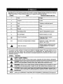
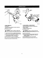
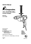
Operator's Manual
1/2 in. ELECTRIC DRILL
Variable Speed / Reversible
Double Insulated
Model Nos.
315.101130
Ryobi
Save this manual for
future reference.
• Safety
• Features
A, CAUTION:
Read and follow
all Safety Rules and Operating
Instructions before first use of
• OperaUon
• Maintenance
• Parts List
this product.
Customer Help Line: 1o800-932-3188
Sears, Roebuck and Co., 3333 Beverly Rd., Hoffman
Visit the Craftsman web page: www.sears.com/craftsman
972000-999
10-02
Estates,
IL 60179
USA
0( us
•
Table of Contents
.....................................................................................................................................................
•
General Safety Rules ............................................................................................................................................
2
2-3
•
Specific Safety Rules ...............................................................................................................................................
4
•
Symbols ....................................................................................................................................................................
5
•
Features
6
•
Operation .............................................................................................................................................................
•
Maintenance
...........................................................................................................................................................
11
•
Accessories
............................................................................................................................................................
12
•
Warranty
•
Exploded View and Repair Parts List .....................................................................................................................
13
•
PartsOrdering/Service
14
A
...................................................................................................................................................................
..........................................................
;...,.L ................................................................................................
.........................................................................................................................................
WARNING: Reed and understand all
Instructions. Failure to follow all instructions
listed below may result in electricshock, fire,
and/or serious personal injury.
SAVE THESE INSTRUCTIONS
Work Area
•
Keep yourwork area clccn and well lit. Cluttered
benches and dark areas inviteaccidents.
•
Do not operate power tools in an(plosive atmospheres, such as In the presence of flammable
Keep bystanders, children, and visitors away
white operating a power tool. Distractions can
cause you to lose control.
Electrical Safety
•
Double Insulated tools are equipped with a
polarized plug (one blade Is wider than the other).
This plug will fit In a polerlzed outlet only one
way. If the plug does not fit fully in the outlet,
reverse the plug. If It STIll does not fit, contact a
qualified electrlolan to Install a polerlzed outlet.
Do not change the plug In any way. Double
insulation[] eliminates the need for the three-wire
groundedpower cord and groundedpower supply
system.
• Avoid body contact with grounded surfaces,
such as pipes, radiators, ranges, and refrigerators. There is an increased risk of electricshock if
your body is grounded.
,_
•
Don't expose power tools to rain or wet conditions. Water entenng a power tool will increasethe
riskof electricshock.
• Do not abuse the cord. Never use the cord to
carw the tools or pull the plug from an outlet.
12
Keep cord away from heat, o11,sharp edges, or
moving pads. Replace damaged cords immediately. Damaged cords increase the risk of electric
shock.
• When operating a power tool outside, use an
outdoor extension cord marked "W-A" or "W."
These cords are rated for outdoor use and reduce the
risk of electric shoci_
Personal Safety
•
liquids, gases, or dust. Power tools create s_arks
which may ignite the dust or fumes.
•
7-10
Stay alert, watch what you are doing, and use
common sense when operating a power tool. Do
not use tool white tired or under the influence of
drugs, alcohol, or mndicatlon. A momentof inattention while operatingpower tools may result in serious
personalinjury.
•
Dress properly. Do not wear loose clothing or
JawstW. Contain long hair. Keep your hair, clothIng, and gloves away from moving pads. Loose
clothes, jewelry, or long hair can be caught in moving
parts.
• Avoid accidental starUng. Be sure switch is off
before plugging In. Carryingtools with yourfinger
on the switchor pluggingin tools that have the switch
on invitesaccidents.
•
Remove adjusting keys or wrenches before
tumlng the tool on. A wrench or a key that is lef_
attached to a rotating part of the tool may result in
personal injury.
• Do not overreach. Keep proper footing and
balance at all times. Proper footingand balance
enables better controlof the tool in unexpected
situations.
• Use setstyequipment.Alwayswccr aye protection. Dust mask, nonskidsafety shoes, hard hat, or
hearing protectionmust be used for appropriate
conditions.
ToolUseandCare
•
Use clamps or other practical way to secure and
support the workpiece to a stable platform.
Holding the work by hand or against your body is
unstable and may lead to loss of control.
•
Do not forcetool.
Uso the correct tool for your
application. The correct tool will do the job better
and safer at the rate for which it is designed.
•
Do not use tool if switch does not turn it on or off.
Any tool that cannot be controlled with the switch is
•
•
dangerous and must be repaired.
Disconnect the plug from the power source
before making any adjustments, changing acceesorles, or storing the tool. Such preventive safety
measures reduce the risk of starting the tool accidentally.
Store Idle tools out of the reach of children and
other untrained persons. Tools are dangerous in
the hands of untrained users.
•
Mslntatn tools wifh sere, Keep cutUng tools sherp
and clean. Properly maintained tools with sharp
cuttingedges are less likelyto bind and are easier to
control.
II1 Check for mlsallgnment or binding of moving
parts, breakage of parts, and any other condition
that may affect thetoors
operation, if damaged,
have the tool son/Iced before using. Many accidents are caused by poorly maintained tools,
•
Use only accessories that are recommended by
the manufacturer
for your model. Accessories that
may be suitable for one tool may become hazardous
when used on another tool.
SewIce
• Tool service must be performed only by qualified
repair personnel. Service or maintenance performed
by unqualifiedpersonnel could resultin a risk of
injury.
• When servicing a tool, use only identical replacemerit parts. Follow Instructions in the Maintenance section of this manual, Use of unauthorized
parts or failure to follow Maintenance Instructions
may create a risk of electricshock or injury.
Hold tool by Insulated gripping surfaces when performing an operation where the cutting tool may contact
hidden wiring or its cord. ContaCt with a "live" wire will make exposed metal parts of the tool "live" and shock the
operator.
Additional
Rules for Safe Operation
•
Know your power tool. Read operator's manual
carefully. Learn Its appllcafions end limitations, as
well as the specific potential hazards related to this
tool. Followingthis rule will reduce the risk of electric
shock,fire, or sedous injury.
•
Always wear safety glasses. Everyday eyeglasses
have only Impact-resistant lenses; they are NOT
safety glasses. Following this rule will reducet_e risk
of serious personal injury.
•
Proteof your lungs.Wear a faoeor duaf mask If the
operation Is dusty. Followingthis rule will reducethe
risk of serious personal injury.
•
Protect your hearing. Wear hearieg protectio o during extended periods of operation. Following this
rule will reduce the risk of serious personal injury.
•
Inspect tool cords periodically end, if damaged,
have repaired at your nearest Factory Service
Center or other Authorized Service Organization. Constantly stay aware of cord location.
Followingthis rule will reduce the risk of electric
shock or fire.
•
•
Check damaged parts. Bofore further use of the
tool, a guard or other part thai Is damaged should
be carefully checked to daterrnlne that It will
operate properly and perform Its Intended function. Check for alignment of moving parts, I_nding
of moving pads, breakage of parts, mounting, end
any other conditions that may affect Its operation.
A guard or other part that is damaged should be
properly repaired or replaced by an authorized
senrlce center. Followingthis rule will reduce the
risk of electric shock, fire, or serious injury.
Don't abuse cord. Never carry the tool by the
cord or yank it to disconnect It from the receptacle. Keep cord away from heat, o11,and sharp
edges. Followingthis rule will reduce the risk of
electricshock or fire.
• Make sure your extension cord is In good conditlon. When using an e=tenslon cord, be sure to
use one heavy enough to carry the current your
product will draw. A wire gage size (A.W.G,) of at
least 16 is recommended for an extension cord
100 feet or less In length. A cord e_caeding 100
feat Is not recommended. If In doubt, use the
next heavier gage. The smaller the gage number,
the heavier the cord. An undersized cord will cause
a drop in line voltage resulting in loss of power and
overheating.
• Inspact for and remove all naifs from lumber belore
drilling. Following this rule will reduce the risk of
serious personal injury.
•
Drugs, alcohol, medlcafion. Do not operate tool
whife under the Influence of drugs, alcohol, or any
medioetlon. Followingthis rule will reduce the risk of
electricshock,fire, or serious personal injury
•
Save these Inelruofions. Refer to them frequently
and use them to instruct others who may use this
tool. Ifyou loan someonethls tool, loan them these
Inafruoflons also.
&
WARNING: Some dust created by power
sanding, sawing, grinding, drilling, and other
constructionactivities contains chemicals known
to cause cancer, birth defects or other
reproductive harm. Some examples of these
chemicals are:
lead from lead-based paints,
crystalline silica from bricks and cement and
other masonry products, and
arsenic and chromium from chemicallytreated lumber.
Your risk from these exposures varies,
depending on how often you do this type of work.
To reduce your exposure to these chemicals:
work in a well ventilated area, and work with
approved safety equipment, such as those dust
masks that are specially designed to filter out
microscopic particles.
SAVE THESE INSTRUCTIONS
Important: Some of the following symbols may be used on your tool. Please study them and learn their meaning.
Proper interpretation of these symbols will allow you to operate the tool better and safer.
SYMBOL
NAME
D ESIG NATIO N/EXP LANATIO N
V
Volts
Voltage
A
Amperes
Current
Hz
Hertz
Frequency (cycles per second)
W
Watt
Power
Minutes
Time
Alternating Current
Type or a characteristic of current
no
No Load Speed
Rotational speed, at no load
[]
Class II Construction
Designates Double Insulated
Construction tools
Revolutions or Reciprocation Per Minute
Revolutions, strokes, surface speed,
orbits etc. per minute
min
.../rain
,_
Indicates danger, warning or caution.
It means attention!![ Your safe_y is
involved.
Safety A(ert Symbol
The purpose of safety symbols is to attract your attention to possibledangers. The safety symbols, and the
explanations with them, deserve your careful attention and understanding.The safety warnings do not by
themselves eliminate any danger. The instructionsor warningsthey give are not substitutesfor proper accident
prevention measures.
SYMBOL
MEANING
,l_
SAFETY ALERT SYMBOL:
Indicatesdanger,warning,or caution. May be used in conjun_on with othersymbolsor pictographs.
_k
DANGER:
Failureto
obey a safety
warningwillresultinsedous
injurytoyoumelforto
othem.Always
follow
the safety
precautionsto
reducethe
risk of fire, electricshock
and personal injury.
._
WARNING:
to obey
a safetytowarning
result
in serious
to and
yourself
or to injury.
others.
Always follow Failure
the safety
precautions
reduce can
the risk
of fire,
electric injury
shock
personal
,_k
CAUTION: Failure to obey a safety warning may result in propertydamage or personal injuryto
yourselfotto others,Always follow the safety precautionstoreducethe riskof fire, electricshockand
personal injury.
NOTE:
Advises you of informationor instructionsvital to the operationor maintenance of the equipment.
5
KNOWYOURELECTRICDRILL
APPLICATIONS
See Figure 1.
(Use only for the purpose limed below)
Before attemptingto use your drill, familiarize yourself
with all operating features and safety requirements,
•
Drillinginwood.
•
Drillingin ceramics, plastics, fiberglass, and lami
nafas.
•
•
Drillingin both hard and soft metals.
Using drivingaccessories, such as drivingscrews
with screwdriverbits.
•
Mixing paints.
Your drill has many features for making drilling operations more pleasant and enjoyable. Safety, performance, and dependability have been given top priority
in the design of this drill making it easy to maintain and
operate.
,_
CAUTION: Carefully read through this entire
operator's manual before using your new drill. Pay
close attentionto the Rules For Safe Operation,
Warnings,and Cautions. If you use your drill
properly and onlyfor what it is intended,you will
enjoy years of safe, reliableservicel
ELECTRICAL
PRODUCT SPECIFICATIONS
Chuck Capacity...................................................... 1/2 in.
input ............................................... 120 Volts,AC, 60 Hz
Rating .......................................................... 6.0 Amperes
No Load Speed ............................................. 0-800 RPM
Switch ................................... Variable Speed/Reversible
CONNECTION
Your drill has a precision built electric motor. It should
be connected to a power supply that Is 120 volts, 60
HZ, AC only (normal household current), Do not
operate this tool on direct current (DC), A substantial
voltage drop will cause a loss of power and the motor
will overheat, If your drill does not operate when
plugged into an outlet, double-checkthe power supply.
LEVEL
A convenient"newfeature provided with your drillis a
level, it is recessed in the motor housingon top and end
of your drill. It can be used to keep drillbits level during
drillingoperations.
LEVEL
LEVEL
AUXIUARY
HANDLE
ASSEMBLY
CHUCK KEY
LOCK-ON
TRIGGER
FORWARD-REVERSE
LEVER
CHUCKKEY
STRAP
Fig. 1
,_
WARNING: Do not allow familiarity with tools to make you careless. Remember that a careless fraction of a
second is sufficient to inflict severe injury. '=
6
,_
WARNING:
If any parts are missing, do not
operate this tool until the missing parts are
replaced. Failure to do so could result in possible
serious personal injury.
WARNING: Always wear safety goggles or safety
glasses with side shields when operating your drill.
Failure to do so could result in dust, shavings,
loose particles or foreign objectsbeing thrown into
your eyes, causing possibleserious injury,
SWITCH
See Figure 2.
To turn your drill ON, depress the switchtrigger.
Release switchtrigger to turn your ddlt OFF.
REVERSE
FORWARD
FORWARDREVERSELEVER
Fig. 3
the switch tdgger and allow the drillto stop before
changing its direction.
Note: Your drill will not run unlessthe switchlever is
pushed fully to the le_ or right.
VARIABLE SPEED
See Figure 4.
LOCK-ON
BUTt'ON
TBGGER
Fig, 2
LOCK-ON BUTTON
See Figure 2.
TO INCREASESPEED,
PULL S_NITCHTRIGGER
Fig. 4
Your drill is equipped with a lock-on feature, which is
convenientwhen continuousdrillingfor extended
periods of time is required. To lock-on, depressthe
switchtngger, push in and hold the lock-on button
Your drill has a variable speed switch designedto allow
operator contrel of speed and torque limits. The speed
and torque of your drillcan be increased by depressing
the switch trigger.
locatedon the side of the handle, then release s_itch
trigger. Release lock-on button and your drillwill
continuerunning.
Note: Depress switch trigger all the way for maximum
speed and torque of your drill. Depress switchtrigger
only pa.,_of the way for less speed and torque.
Avoid running your ddll at low speeds for extended
periods of time. Running at low speeds under constant
usage may cause your drill to become overheated. If
this occurs, cool your drill by running it without a load
and at full speed.
To release the lock, depress the switch trigger and
release.
If you have the lock-on feature engaged dudng use and
your drillbecomes disconnectedfrom power supply,
disengage the lock-onfeature immediately.
REVERSIBLE
See Figure 3.
Your electric drillhas the feature of being reversible.
The direction of chuck rotation is controlled by a button
locatedabove the switch trigger. With your drill held in
normal operating position,the direction of rotation lever
should be positionedto the left of the switch for drilling.
The drill direction is reversed when the button is to the
right of the switch.
The design of the switch will not permit changing the
direction of rotationwhile the drill is running.Release
The following guidelines may be used in determining
correct speed for various applications:
• Low speed is ideal when minimum speed and power
is required. For example: starting holes without
canter punching, driving screws, mixing paint, and
drilling in ceramics.
• Medium speed is suitable for drilling hard metals,
plastics, and laminates.
• High speed produces best results when maximum
power is required. For example: drilling in wood, soft
metals such as aluminum, brass, and copper, and
when using driving accessories.
A
TO INSTALL BITS
See Figures 6 and 7.
WARNING: Your drillshould never be connected
to power supply when you are assembling parts,
makingadjustments, installingor removing ddll
bits, cleaning, or when not in use. Disconnecting
your drill will prevent accidental starting that could
cause serious personal injury.
INSTALLING
ASSE M B LY
See Figure 5.
AUXILIARY
•
Unplug your drill.
CHUCKBODY
HANDLE
DRILLBIT
An auxiliary handle is packed with your drill for ease of
operation and to help prevent loss of control. The
handle can be rotated 360° and it can also be mounted
on the opposite side for left hand use.
CHUCKJAWS
CHUCKCOLLAR
RIGHT
Note: For convenience and ease of starting threads, the
hex nut has been trapped inside the molded slot in the
auxiliary handle.
•
_ll
_1
Unplug your drill.
WARNING: Failure to unplug your drillcould
result in accidental starting causing serious injury,
Fig. 6
WARNING: Failure to unplug your drillcould
result in accidental starting causing serious injury,
•
Open or close the chuck jaws to a point where the
opening is slightly larger than the drill bit you intend
to use. Also, raise the front of your drill slightly to
keep the drill bit from falling out of the chuck jaws.
Insert drill bit into chuck the full length of the jaws.
•
Remove auxiliary handle from plastic bag.
•
Loosen handle enough to mal_ opening large enough
to fit over chuck.
•
•
Slide ring of handle over chuck. Note: Handle fits on
neck of gear housing.
Rotate handle to desired operating position.
_1= WARNING: Do not insert drill bit into chuckjaws
and tighten as shown in figure 7. This could cause
ddll bit to be thrown from your ddll resulting in
possibleserious personal injuryor damage to your
chuck.
•
•
Securely tighten
clockwise.
by turning the auxiliary handle
To Adjust:
• TO adjust, loosen the aL_iliery handle assembly
turning the handle counterclockwise.
by
•
Rotate auxiliary handle assembly to desired operating
position.
•
Securely tighten
clockwise.
by turning
the
auxiliary
handle
CHUCK
\
Fig. 7
• Tighten chuck jaws securely using the chuck key
provided. DO NOT use a wrench to tighten or loosen
the chuck jaws.
• Remove chuck key and return to storage area.
AUXIUARYHANDLE
ASSEMBLY
Fig, 5
8
TO REMOVE BITS
•
_
• Depressand releaseswitchtriggerto be sureyour
Unplug your ddll.
•
WARNING:
Failure to unplug your ddll
could result in accidental starting causing
serious injury,
•
•
Loosen the chuck jaws using onlythe chuck key
provided.
• Do not use a wrench to tighten or loosen the chuck
jaws.
• Remove drillbit from chuck jaws.
•
ddll is in OFF position before connecting it to power
supply.
Check the direction of rotation lever for correct
setting (forward or reverse). See Figure 3.
Secure the material to be drilled in a vise or with
clamps to keep it from turning as the drill bit rotates.
•
Plug your ddll into power supply source.
•
Hold your ddll firmly and place bit at point to be
drilled.
Depress the switchtrigger to start your drill. Do not
lock the switch ON for jobs where your drill may
need to be stopped suddenly.
Remove the chuck key.
DRILLING
See Figures 8 and 9,
Move the drillbit intothe workpiece applyingonly
enough pressure to keep the bit cutting. Do not force
your drillor apply side pressure to elongate a hole.
Let your ddll and bit do the work. See Figures 8
and 9.
LEVEL
_1_ WARNING: Be prepared for binding or bit
break_hreugh. When these situations occur, drill
has a tendency to grab and kickoppositeto the
directionof rotationand could cause loss of control
when breaking through materials. If not prepared,
this loss of controlcan resultin possibleserious
injury.
END VIEW
When drilling hard, smooth surfaces use a center punch
to mark the desired hole location. This will prevent the
drill bit from slipping off center as the hole is started.
However, the variable speed feature allows starting
holes without center punching if desired. To accomplish
this, operate your drill at a low speed until the hole is
started.
When drillingmetals use a light oil on the drill bit to
keep it from overheating.The oilwill prolong the life of
the bit and increase the drilling action.
If the bit jams in the work piece or if your drill stalls, stop
the tool immediately. Remove the bit from the work
piece and determine the reason for jamming.
LEVEL DRILLING
See Figures 8 and 9.
Fig. 8
9
A convenientfeature providedon your drillis a level, it
is recessed in the motor housingon your drill, It can be
used to keep ddll bits level during both hedzontal and
vertical drillingoperations,
TOPVIEW
LEVEL
Fig. 9
TO RETIGHTEN
CHUCK REMOVAL
See Figure 10.
The chuck must be removed in order to use some
accessories. To remove:
•
Fig, 10
A LOOSE CHUCK
The chuck may become looseon the spindle and
develop a wobble.
To tighten, followthese steps:
• Unplug your drill.
Unplug yourdrill.
,_lb WARNING: Failure to unplug your drillcould
resultin accidental starting causing serious injury,
,_
•
Insert a 8 mm (5/16 in.) or larger hsx key into the
chuck of your drill and tighten chuck jaws securely.
•
Tap the hex key sharply with a mallet in a
counterclockwise direction. See Figure 1G
• Open the chuck jaws.
• Insert hex key intochuck and tighten chuck jaws
securely. Tap hex key sharply with a mallet in a
clockwisedirection.
•
This will loosen the chuck on the spindle,
•
This will tighten the chuck on the spindle.
•
It can now be unscrewed
•
Open the chuck jaws and remOVethe hex key,
•
Open chuck jaws and remove hex key.
by hand, See Figure 10.
10
WARNING: Failure to unplug your drill could
resultin accidental starting causing sedous injury.
GENERAL
DOUBLE
Only the parts shown on parts list, page 13, are ,M
intended to be repaired or replaced bythe customer. All
other parts represent an important part of the double
insulation system and should be serviced only at a
Sears Service Center.
Double insulationis a concept in safety in electric
power tools, which eliminates the need for the usual
three-wire groundedpower cord. All exposed metal
parts are isolated from the internalmetal motor
componentswith protectinginsulation.Double insulated
tools do not need to be grounded.
Avoid using solventswhen cleaningplastic pans. Most
plastics are susceptible to damage from various types
of commercial solvents and may be damaged by their
use. Use clean cloths to remove dirt, carbon dust, etc.
,_
IMPORTANT
Servicingof a tool with double insulationrequires
extreme care and knowledgeof the system and should
be performed only by a qualified service technician. For
service, we suggest you ratum the tool to your nearest
Sears store for repair.Always use originalfactory
replacement parts when servicing.
EXTENSION CORDS
WARNING:
Do not at any time let brake fluids,
gasoline, petroleum-based products, penetrating
oils, etc. come in contact with plastic parts. They
contain chemicals that can damage, weaken or
destroy plastic.
It has been found that electric tools are subjectto
accelerated wear and possible premature failure when
they are used on fiberglass boats, sports cars,
wallboard,spacklingcompounds, or plaster. The chips
and gnndingsfrom these materials are hightyabr&sive
to electric tool parts, such as bearings, brushes,
commutators,etc. Consequently, it is not recommended
that this tool be used for extended work on any
fiberglass material, wallboard, spackling compounds,or
plaster. During any use on these materials, it is
extremely important that the tool is cleaned frequently
by blowingwith an air jet.
LUBRICATION
All of the bearings in this tool are lubricated with a
sufficient amount of high-grade lubricant for the life of
the unit under normal operating conditions. Therefore,
no further lubrication is required.
A
INSULATION
The usa of any extension cordwill cause some loss of
power. To keep the loss to a minimum and to prevent
tool overheating, use an extension cord that is heavy
enoughto carry the currentthe tool will draw.
A wire gage size (A.W.G.) of at least 16 is
recommendedfor an extension cord 100 feet or less in
length.When working outdoors,use an extensioncord
that is suitablefor outdoor use, The cord'sjacket will be
marked WA.
• IL CAUTION: Keep extension cordsaway from the
drillingarea and positionthe cord so that it will not
get caught on lumber,tools, etc., during drilling
operation.
_lk
WARNING: Always wear safety goggles or safety
glasses with side shields during power tool operation or when blowingdust. If operation is dusty,also
wear a dust mask.
11
WARNING:
Check extension cords before each
use. If damaged replace immediately. Never use
tool w_h a damaged cord since touching the
damaged area could cause electrical shock resulting in sadous injury.
Extension cordssuitablefor use with yourdrill are
available at your nearest Sears Retail Store,
The following recommended accessoriesare currently available at Seats retail stores.
•
High Speed Bt_s (For wood or metal)
1/2 in. Max.
•
Masonry Bits
3/4 in. Max.
•
Wood Boring Bits
•
HoleSaws
_i,
WARNING:
1-1/4 in. Max.
2 in. Max.
The use of attachmentsor accessories not listed mightbe hazardous.
,A, WARNING:
The operation of any drill can result in foreign objects being thrown into your eyes, which
can result in severe eye damage, Before beginning power tool operation, always wear
safety goggles or safety glasses with side shields and a full face shield when needed. We
recommend Wide Vision Safety Mask for use over eyeglasses or standard safety glasses
with side shields. Always wear eye protection which is marked to comply with ANSI Z87.1.
FULL ONE YEAR WARRANTY ON CRAFTSMAN DRILL
If this CRRI=TSMRMDrillfails to give complete satisfactionwithin one year from the date of purchase, RETURN IT
TO THE NEAREST SEARS STORE IN THE UNWED STATES, and Seats will repair it, free of charge.
If this rRRFTSMRN Drill is used for commercial or rental purposes, this warranty applies for only 90 days from the
date of purchase.
This warranty gives you specific legal rights,and you may also have other rightswhich vary from state to state.
Sears, Roebuck and Co., Depl. 817WA, Hoffwmn Estates, IL 60179
SAVETHESEINSTRUCTIONS
12
CRAFTSMAN
1/2 in. ELECTRIC
MODEL NO. 315.101130
DRILL
!
The model number will be found on a plate attached to the motor housing. Always mention the model
number in all correspondence regarding your ELECTRIC DRILL or when ordering repair parts.
SEE BACK
PAGE
FOR PARTS
ORDERING
|
I
INSTRUCTIONS
2
I
3
'PARTS LIST
Key No.
Part
No.
1
6909005
2
3
Description
Quan.
9421440
112 in. Chuck .......................................................................................
Data Plate ....................................
_......................................................
I
1
9421330
Logo Plate ...........................................................................................
1
972000-999
Operator's Manual
13
1-877-LE-FOYER
1-888-SU-HOGAR
=
(1-877-533-6937)
:===_
® Regi_ered
(D Se_'s,
Ro_b uof. _ d Co.
®Matca
Tradern_k
Regist rad8 /
TM
!
TM
M_'_a
Tr _d_tlatk
of Se_,
de Filb tic8 de _S,
Roe_ u(:_ and Co.
ROebuCk _ d Co.
_