1
Go To Table Of Contents
M9 / M9D
M11 / M11D
To purchase a printed copy of this manual,
click on the "Place Order" button below.
Place Order
-001 thru -019
Self-Contained Steam Sterilizer
Serial Number Prefixes:
M9 [CZ, DA, DB, DX, DY, FK, LA, FL, OM]
M9D [FF, FG]
M 11 [ES, ET, FP, FR, GB. NP]
M11D [GC, GD]
NO
LO
Som PRO NGE
R
D
e
U
IN
ser
be
C
TIO
vice
ava
N
ilab
p
ar ts
le f
or t
ma
yn
his
ot
pro
duc
t!
M9/D
M11/D
-001 thru -019
FOR USE BY MIDMARK TRAINED TECHNICIANS ONLY
SF-1827
Part No. 004-0372-00 Rev. F (1/01/08)
Go To Table Of Contents
TABLE OF CONTENTS
Section/Paragraph
Page
IMPORTANT INSTRUCTIONS
General Safety Instructions......................................... iii
Safety Alert Symbols .................................................. iii
Warranty Instructions .................................................. iii
SECTION I GENERAL INFORMATION
1.1 Model / Serial Number Location................... 1-1
1.2 Specifications .............................................. 1-1
1.3 Description of Normal Operation .................. 1-2
1.4 Ordering Parts ............................................. 1-3
1.5 Special Tools .............................................. 1-4
SECTION II TESTING AND TROUBLESHOOTING
2.1 Operational Test .......................................... 2-1
2.2 Troubleshooting Procedures ........................ 2-1
SECTION III SCHEDULED MAINTENANCE
3.1 Scheduled Maintenance .............................. 3-1
SECTION IV MAINTENANCE/SERVICE
INSTRUCTIONS
4.1 Safety Precautions...................................... 4-1
4.2 Top Cover Removal / Installation ................ 4-1
4.3 Right Hand Side Panel Removal /
Installation .............................................. 4-1
4.4 Left Hand Side Panel Removal /
Installation .............................................. 4-2
4.5 Back Panel Removal/Installation ................. 4-3
4.6 Base Inspection Cover Removal /
Installation .............................................. 4-3
4.7 Bellows Assembly Removal / Installation .... 4-4
4.8 Condensing Tank Water Level Sensor
Removal / Installation ............................. 4-5
4.9 Temperature Sensor Assembly
Removal / Installation ............................. 4-6
4.10 Pressure Vessel Water Level Sensor
Removal / Installation ............................. 4-6
4.11 Vent Solenoid Removal / Installation ........... 4-7
4.12 Fill Solenoid Removal / Installation ............. 4-9
4.13 Control PC Board Removal / Installation ... 4-10
4.14 Door Switch Removal / Installation ............ 4-13
4.15 Pulse Solenoid Removal / Installation ....... 4-13
4.16 Thermostat Removal / Installation ............. 4-14
4.17 Wire Tray Rack and Tray Plate
Removal / Installation ........................... 4-15
Section/Paragraph
Page
4.18 Heating Element and Gasket
Removal / Installation ........................... 4-15
4.19 Filter Removal / Installation ....................... 4-16
4.20 Door Gaskets Removal / Installation ......... 4-17
4.21 Display PC Board Removal / Installation ... 4-17
4.22 Condensing Tank Assembly
Removal / Installation ........................... 4-18
4.23 Pressure Relief Valve Removal /
Installation ............................................. 4-19
4.24 Pressure / Temperature Potentiometers
Adjustments ......................................... 4-20
4.25 Display PC Board Lamp / Display /
Button Check ........................................ 4-23
4.26 Pressure Relief Valve Check ..................... 4-24
4.27 Dry Cycle Dip Switches Adjustment ........... 4-25
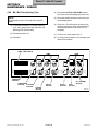
4.28 M9 / M11 Door Opening Test ..................... 4-26
SECTION V SCHEMATICS AND DIAGRAMS
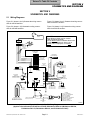
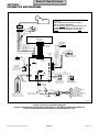
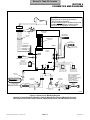
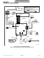
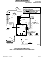
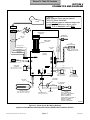
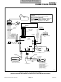
5.1 Wiring Diagrams .......................................... 5-1
5.2 Flow Diagram ............................................ 5-11
5.3 Pressure / Temperature Chart .................... 5-12
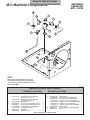
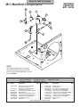
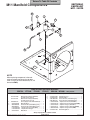
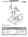
SECTION VI PARTS LIST
6.1 Description of Bullets ................................... 6-1
6.2 Torque Specifications and Important
Assembly Notes ...................................... 6-1
NOTE: The Parts List in this manual is divided
into two sections [M9 / M9D & M11/M11D].
Verify model and refer to appropriate section.
M9 / M9D Parts List
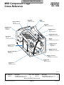
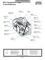
M9 Component / Page Cross-Reference ..... 6-2
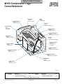
M9D Component / Page Cross-Reference .... 6-3
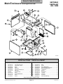
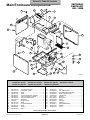
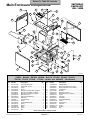
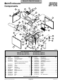
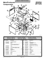
Main Enclosure Components ...................... 6-4*
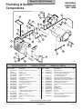
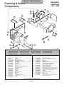
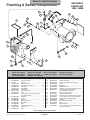
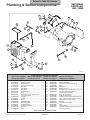
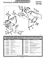
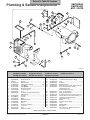
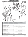
Plumbing and Sensor Components ............ 6-5*
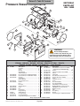
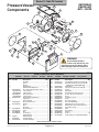
Pressure Vessel Components .................... 6-6*
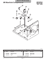
M9 Manifold Components ........................... 6-7*
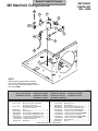
M9D Manifold Components ........................ 6-8*
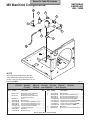
Electrical Components ............................... 6-9*
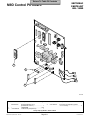
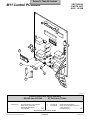
M9 Control PC Board ............................... 6-10*
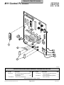
M9D Control PC Board ............................... 6-11
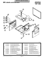
M9 Labels and Decals ............................... 6-12
M9D Labels and Decals ............................ 6-13
Printer Components .................................. 6-14
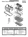
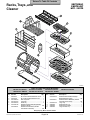
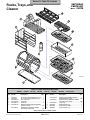
Racks, Trays, and Cleaner ....................... 6-15*
Packaging ................................................. 6-16
(*) Indicates that there has been a serial number break for the illustration
and that there are additional point page(s) following the original page.
© Midmark Corporation 2002 SF-1827
Page i
Printed in U.S.A.
TABLE OF CONTENTS
Section/Paragraph
Page
SECTION VI PARTS LIST - continued
NOTE: The Parts List in this manual is divided
into two sections [M9 / M9D & M11/M11D].
Verify model and refer to appropriate section.
M11 / M11D Parts List
M11 Component / Page
Cross-Reference ................................... 6-17
M11D Component / Page
Cross-Reference .................................... 6-18
Main Enclosure Components.................... 6-19*
Plumbing and Sensor Components .......... 6-20*
Pressure Vessel Components .................. 6-21*
M11 Manifold Components ....................... 6-22*
M11D Manifold Components .................... 6-23*
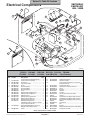
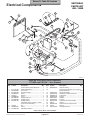
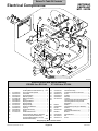
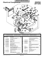
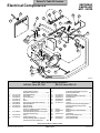
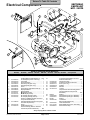
Electrical Components ............................. 6-24*
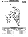
M11 Control PC Board ............................. 6-25*
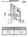
M11D Control PC Board ............................. 6-26
M11 Labels and Decals ............................. 6-27
M11D Labels and Decals .......................... 6-28
Printer Components .................................. 6-29
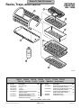
Racks, Trays, and Cleaner ....................... 6-30*
Packaging ................................................. 6-31
COMMENTS ............................................................ 7-1
FAX ORDERING FORM .......................................... 7-2
© Midmark Corporation 2002 SF-1827
Page ii
Printed in U.S.A.
Return To Table Of Contents
IMPORTANT INSTRUCTIONS
General Safety Instructions
NOTE
Safety First: The primary concern of Midmark
Corporation is that this sterilizer is maintained with the
safety of the patient and staff in mind. To assure that
services and repairs are completed safely and correctly,
proceed as follows:
(1) Read this entire manual before performing any
services or repairs on this sterilizer.
(2) Be sure you understand the instructions contained in this manual before attempting to
service or repair this sterilizer.
Safety Alert Symbols
Throughout this manual are safety alert symbols that
call attention to particular procedures. These items are
used as follows:
DANGER
A DANGER is used for an imminently
hazardous operating procedure, practice, or condition which, if not correctly followed,
will result in loss of life or serious personal
injury.
A NOTE is used to amplify an operating procedure,
practice or condition.
Warranty Instructions
Refer to the Midmark “Limited Warranty” printed in the
Installation and Operation Manual for warranty information. Failure to follow the guidelines listed below will
void the warranty and/or render the M9 sterilizer unsafe
for operation.
• In the event of a malfunction, do not attempt to
operate the sterilizer until necessary repairs have
been made.
• Do not attempt to disassemble sterilizer, replace
malfunctioning or damaged components, or perform
adjustments unless you are one of Midmark’s
authorized service technicians.
• Do not substitute parts of another manufacturer when
replacing inoperative or damaged components. Use
only Midmark replacement parts.
WARNING
A WARNING is used for a potentially
hazardous operating procedure, practice, or condition which, if not correctly followed,
could result in loss of life or serious personal
injury.
CAUTION
A CAUTION is used for a potentially
hazardous operating procedure, practice,
or condition which, if not correctly followed, could
result in minor or moderate injury. It may also be
used to alert against unsafe practices.
EQUIPMENT ALERT
An EQUIPMENT ALERT is used for an
imminently or potentially hazardous
operating procedure, practice, or condition which, if
not correctly followed, will or could result in serious,
moderate, or minor damage to unit.
© Midmark Corporation 2002 SF-1827
Page iii
Printed in U.S.A.
Return To Table Of Contents
Return To Table Of Contents
SECTION I
GENERAL INFORMATION
SECTION I
GENERAL INFORMATION
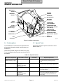
1.1 Model / Serial Number Location
MODEL NUMBER
A
D
SERIAL NUMBER
C
B
MA2071-01
Figure 1-1. Model / Serial Number Location
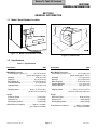
Figure 1-2. Dimensions
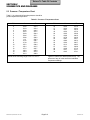
1.2 Specifications
Table 1-1. Specifications
Description
Data
Description
Data
M9 / M9D Dimensions:
Front Height (A, Figure 1-2) .............. 16.4 in (41.8 cm)
(printer adds approx. 0.5 in)
Width (B) .............................................. 15 in (38.1 cm)
Depth (C) .......................................... 18.1 in (47.8 cm)
Back Height (D) ............................... 13.75 in (34.9 cm)
Chamber Diameter .................................9 in. (22.8 cm)
Chamber Depth .................................... 15 in. (38.1 cm)
M11 / M11D Dimensions:
Front Height (A, Figure 1-2) .............. 17.7 in (44.9 cm)
(printer adds approx. 0.5 in)
Width (B) ........................................... 17.6 in (44.8 cm)
Depth (C) .......................................... 22.4 in (56.8 cm)
Back Height (D) ............................... 15.25 in (38.7 cm)
Chamber Diameter ............................... 11 in. (27.9 cm)
Chamber Depth .................................... 18 in. (45.7 cm)
Shipping Carton ....................... 22 in x 17.75 in x 18 in
(56 cm x 45 cm x 46 cm)
Shipping Carton ...................... 23 in x 27.5 in x 21.5 in
(58.4 cm x 69.8 cm x 54.6 cm)
Weight:
Reservoir Empty ...................................... 70 lb (32 kg)
Reservoir Full ........................................... 77 lb (35 kg)
With Shipping Carton ............................... 78 lb (36 kg)
Weight:
Reservoir Empty ................................... 96 lb (43.5 kg)
Reservoir Full ......................................... 106 lb (48 kg)
With Shipping Carton ............................. 128 lb (58 kg)
Water Reservoir Capacity ................ Approx. 7/8 gallon
(3.31 Liters to full mark)
Water Reservoir Capacity ............... Approx. 1.25 gallon
(4.7 Liters) to full mark
© Midmark Corporation 2002 SF-1827
Page 1-1
Printed in U.S.A.
Return To Table Of Contents
SECTION I
GENERAL INFORMATION
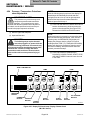
1.3 Description of Normal Operation
NOTE
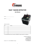
(Figure 1-3 shows Display Panel Buttons & Lamps)
The following information applies to all models of the
M9 / M9D / M11 / M11D included in this manual.
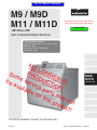
(Figure 1-4 shows location of Major Components)
Plug Power Cord Into Outlet
Display: E001 (Error lamp flashes)
Table 1-1. Specifications - continued
Description
Data
M9 / M9D / M11 / M11D
Electrical Requirements:
100 VAC Unit ............................... 100 VAC 50 - 60 HZ,
15 amp, single phase
115 VAC Unit ...................... 110 - 120 VAC 50 - 60 HZ,
15 amp, single phase
230 VAC Unit ...................... 220 - 240 VAC 50 - 60 HZ,
7 amp, single phase
Power Consumption:
100 VAC Unit ......................................... 1425 WATTS,
15 amps @ 100 VAC
115 VAC Unit ......................................... 1425 WATTS,
12 amps @ 120 VAC
230 VAC Unit ......................................... 1500 WATTS,
7 amps @ 240 VAC
1. Line voltage (100/115/230V) is supplied to Control
PC Board.
NOTE
There are two primary fuses on PC Board. Faulty
fuse(s) will disable all functions of sterilizer.
Press ON/STANDBY Button
Display: (Error lamp goes out; ON/STANDBY lamp
illuminates, & program lamps flash)
Select Cycle (Unwrapped, Pouches, Liquids, Packs)
Display: TIME/TEMP. (for the selected cycle)
Press START Button
NOTE
After the START button is pressed, the PC board
continuously monitors the Door Switch for continuity.
If continuity is not detected, the PC board stops the
cycle, and the Door Ajar lamp illuminates.
Recommended Circuit:
A separate (dedicated) circuit is recommended for
this sterilizer. The sterilizer should not be connected
to an electrical circuit with other appliances or
equipment unless the circuit is rated for the additional load.
1. The Fill Cycle is initiated.
Fill Cycle
Display: (Filling lamp illuminates)
Chamber Pressure:
Operating ........................... 27 - 31 psi (186 - 215 kPa)
Minimum Before Door Is Released
(M9 & M11 only) ................................ 0.7 psi (5 kPa)
Maximum Before Safety Valve
Opens (older units). .......................... 35 psi (241 kPa)
Maximum Before Safety Valve
Opens (newer units). ....................... 40 psi (275.7 kPa)
Chamber Temperature (Operating):
Unwrapped Cycle ................... 272-273 °F (133-134 °C)
Pouches Cycle ...................... 272-273 °F (133-134 °C)
Liquids Cycle ......................... 252-253 °F (122-123 °C)
Packs Cycle .......................... 252-253 °F (122-123 °C)
Maximum Before Thermostat
Energizes ........................................... 295 °F (146 °C)
1. Line voltage from PC Board energizes Fill Solenoid;
this allows water to flow into Pressure Vessel.
2. Water fills Pressure Vessel until it makes contact
with the Pressure Vessel Water Level Sensor.
3. When water completes the ground circuit between
the Pressure Vessel Water Level Sensor & the
chassis, the PC Board de-engergizes the Fill
Solenoid & the Steriliation Cycle is initiated.
Sterilization Cycle
Display: (Sterilizing lamp illuminates)
xxx° (chamber temperature)
xx PSI [after temperature reaches 208°F (98°C)]
NOTE
During the Sterilization Cycle, the Temperature Probe
monitors the chamber temperature and the PC Board
monitors chamber pressure.
© Midmark Corporation 2002 SF-1827
Page 1-2
Printed in U.S.A.
Return To Table Of Contents
SECTION I
GENERAL INFORMATION
TEMP / TIME DISPLAY
LAMP
LAMP
TEMP (°F) \ TIME (MIN : SECONDS)
FILLING
STERILIZING
DRYING
COMPLETE
WATER LOW
DOOR AJAR
ERROR
UNWRAPPED
POUCHES
LIQUIDS
PACKS
START
STOP
ON/STANDBY
PRESSURE (PSI)
PRESSURE
DISPLAY
UNWRAPPED
BUTTON
POUCHES
BUTTON
ON / STANDBY
BUTTON
PACKS
BUTTON
START
BUTTON
STOP
BUTTON
LIQUIDS
BUTTON
MA207702
Figure 1-3. Display Panel Button / Lamp Locations
Sterilization Cycle - continued
3. Control PC Board sounds 5 beeps.
1. Line voltage from PC Board energizes Heating
Element.
4. M9 / M11:
2. Air & steam flow thru Bellows as water in chamber
begins to boil. When temperature reaches approx.
215° F (101° C), the Bellows closes and pressure
begins to build.
M9D / M11D: "Open the Door" Lamp illuminates.
"dddd" appears on Display PC Board.
Manually open door at this time.
Drying Cycle is initiated.
3. When chamber reaches required temperature, Heating
Element is de-energized and sterlization time begins
to count down on Display PC Board.
4. Line voltage from PC Board energizes Heating
Element intermittantly to maintain required
temperature & pressure until time elapses.
Line voltage from PC Board energizes
Pulse Solenoid.
Door opens automatically.
Drying Cycle is initiated.
Drying Cycle
Display: (Drying lamp illuminates)
xx:xx (time counts down from 30 minutes)
(Complete lamp illuminates at end of cycle)
5. When sterilization time expires, the Heating Element
de-energized & the Vent Cycle is initiated.
1. Line voltage energizes Heating Element for
45 seconds. (30 minute countdown begins on
Display PC Board).
Vent Cycle
1. Line voltage from PC Board energizes Vent Solenoid.
[Liquids Cycle requires chamber to cool to 223° F
(106° C) before Vent Solenoid is energized]
2. Heating Element is energized intermittantly (as
shown below) until Dry Cycle is complete.
2. Chamber pressure is released thru Vent Solenoid
until pressure drops to 0.7 psi (4.8 kPa).
45 seconds ON - 2 minutes OFF
30 seconds ON - 2 minutes OFF
xx* seconds ON - 2 minutes OFF (until cycle ends)
*This time is adjustable. Refer to adjustment
procedure in Section IV if necessary.
© Midmark Corporation 2002 SF-1827
Page 1-3
Printed in U.S.A.
Return To Table Of Contents
SECTION I
GENERAL INFORMATION
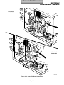
DISPLAY PC
BOARD
HEATING
ELEMENT
PRESSURE
VESSEL
PRESSURE
RELIEF VALUE
BELLOWS
ASSEMBLY
DOOR
SWITCH
CONDENSING
TANK ASSEMBLY
PULSE
SOLENOID
(M9 / M11only)
CONDENSING TANK
WATER LEVEL SENSOR
(early M9 only)
TEMPERATURE
SENSOR ASSEMBLY
CONTROL PC
BOARD
PRESSURE VESSEL
WATER LEVEL SENSOR
THERMOSTAT
VENT
SOLENOID
FILL
SOLENOID
MA207604
Figure 1-4. Major Components
1.4 Ordering Parts
1.5 Special Tools
Contact Midmark's Technical Service Department with
all necessary information (model / serial number, part
number, etc.).
Special tools needed to repair the sterilizer are listed
below in Table 1-2.
Orders can be placed using the Fax Order Form ( page
7-2) or by calling the phone number on the back cover of
this manual.
Table 1-2. Special Tool List
Description of Special Tool
Manufacturer’s
Name / Address / Phone
Manufacturer’s
Part Number
Purpose of Special Tool
Digital Multimeter (must be
capable of displaying 3 digits)
Commercially Available
Any Type
Used to check probes, switches, and connections
for proper function by performing continuity
checks.
Water Level Sensor Wrench
Midmark Corp.
60 Vista Drive
Versailles, Ohio 45380
(513) 526-3662
050-2324-00
Used to hold fitting in place so the nut that holds
water level sensor can be loosened / tightened.
3/32 in. Diameter Punch
Commercially Available
Any Type
Used to remove / install two roll pins which secure
door switch in place or roll pin which secures latch
lever to pulse solenoid.
Pressure Gauge Test Harness
Midmark Corp.
60 Vista Drive
Versailles, Ohio 45380
(513) 526-3662
002-0372-00
Used to check the pressure in the pressure vessel
during a cycle to diagnose malfunctions and / or
adjust the pressure range potentiometer to a
correct setting.
© Midmark Corporation 2002 SF-1827
Page 1-4
Printed in U.S.A.
Return To Table Of Contents
SECTION II
TESTING AND TROUBLESHOOTING
SECTION II
TESTING AND TROUBLESHOOTING
2.1 Operational Test
2.2 Troubleshooting Procedures
To effectively diagnose a malfunction of the sterilizer,
perform the Pressure / Temperature Potentiometers
Adjustment procedure. Refer to para 4.24.
If a malfunction is detected, locate the Problem &
Symptom in Table 2-1. Perform the Check for each
Probable Cause indicated. Follow instructions in the
Correction column as they apply.
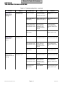
Table 2-1. Troubleshooting Guide
Problem
Error code 1
(Power interruption to
control PC board).
Symptom
Shuts down during
Sterilization cycle.
Shuts down during
Dr ying cycle.
Probable Cause
Check for pressure leaks.
Refer to Table 2-2.
Replace malfunctioning
component at pressure
leak.
Overheat thermostat
activated.
(Not filling properly)
Check that Filling lamp
illuminates. Be sure water
level sensor is dr y.
Replace water level sensor
if necessar y. Refer to para
4.10.
Check that sterilizer is
level.
Adjust sterilizer to level.
Bad electrical
connection(s).
Check sterilizer and facility
for proper electrical
connections.
Tighten / replace loose
connections.
Faulty overheat
thermostat.
(stuck open)
Perform continuity check
on thermostat (N.C.).
Replace thermostat. Refer
to para 4.16.
Overheat thermostat
activated.
(High input voltage)
Check facility input voltage.
Voltage should not exceed
Electrical Requirements as
noted in para 1.2.
Adjust the dr y cycle time
dip switches. Refer to para
4.27.
Check resistance of
heating element. Refer to
para 5.1 for normal
resistance ranges.
If resistance is out of limits,
replace heating element.
Refer to para 4.18.
Perform continuity check
on thermostat (N.C.).
Replace thermostat. Refer
to para 4.16.
Shuts down during cycle.
Stop Button pressed
during cycle.
_
Restar t cycle after beeper
signal stops.
Shuts down during cycle
On / Standby Button
pressed during cycle.
_
Restar t cycle after beeper
signal stops.
Shuts down during cycle
Door latch not closed.
Check if door latch is
engaging switch.
Adjust door latch.
Clean/lubricate door latch
and pins.
Door switch connection
loose.
Check door switch
connection.
Tighten / replace loose
connections.
Door switch
malfunctioning.
Perform continuity check
on door switch (N.O.).
Replace door switch. Refer
to para 4.14.
(Stop Button pressed
during cycle)
Error code 3
(ON / Standby Button
pressed during cycle)
Error code 4
Correction
Overheat thermostat
activated.
(Pressure leak)
Faulty overheat
thermostat.
(stuck open)
Error code 2
Check
(Door Ajar)
© Midmark Corporation 2002 SF-1827
Page 2-1
Printed in U.S.A.
Return To Table Of Contents
SECTION II
TESTING AND TROUBLESHOOTING
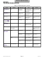
Table 2-1. Troubleshooting Guide - continued
Problem
Error code 5
[Display pressure
exceeded 35 psi
(241 kPa)]
Error code 6
[Display temperature
exceeded 277°F
(136°C)]
Error code 7
[Display pressure
dropped below 24.5 psi
(169 kPa)]
© Midmark Corporation 2002 SF-1827
Symptom
Shuts down during
Strerilization cycle
Shuts down during
Strerilization cycle
Shuts down during
Strerilization cycle
Probable Cause
Check
Correction
Sterilizer overloaded.
Check that pressure
vessel is not overloaded
with heavy linen packs.
Instruct operator to reduce
load size.
Bellows malfunctioning.
(closing early)
Bellows should close at
approx. 212° F (100° C).
Replace bellows. Refer to
para 4.7.
Sterilizer potentiometers
out of calibration and/or
dir ty temperature sensor.
Clean temperature
sensor; then check
calibration of using
Pressure Gauge Test
Harness.
Perform Temperature /
Pressure Potentiometer
Adjustment. Refer to para
4.24.
Temperature sensor
malfunctioning.
Check calibration.
Replace temperature sensor
assembly. Refer to para
4.9.
Slow pressure leak.
Check for pressure
leaks. Refer to Table 2-2.
Replace malfunctioning
component at pressure leak.
Sterilizer potentiometers
out of calibration and/or
dir ty temperature sensor.
Clean temperature
sensor; then check
calibration of using
Pressure Gauge Test
Harness.
Perform Temperature /
Pressure Potentiometer
Adjustment. Refer to para
4.24.
Temperature sensor
malfunctioning.
Check calibration.
Replace temperature sensor
assembly. Refer to para
4.9.
Page 2-2
Printed in U.S.A.
Return To Table Of Contents
SECTION II
TESTING AND TROUBLESHOOTING
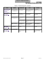
Table 2-1. Troubleshooting Guide - continued
Problem
Error code 8
- M9 & M11 only
[Door switch did
not change status
after door solenoid
was activated.
.
Error code 9
[Pressure
exceeded 0.9 psi
(6.2 kPa) during
Dry cycle]
Symptom
Probable Cause
Check
Correction
Perform continuity check
on door switch. Check for
loose connections.
Replace door switch. Refer
to para 4.14.
Door opens at end of
cycle.
Door switch malfunctioning.
Door does not open at
end of cycle.
Latch lever & pulse solenoid
plunger mechanism
malfunctioning.
Perform M9/M11 Door
Opening Test. Refer to
para 4.28.
Remove any debris or
buildup from latch lever &
pulse solenoid mechanism.
Door pins and latch bracket
not functioning properly.
Check for burrs on door
pins and latch bracket in
door.
Remove burrs; then clean
and lube with lithium based
grease.
Zero pressure potentiometer
out of calibration.
Check calibration of zero
pressure potentiometer.
Adjust zero pressure
potentiometer. Refer to
para 4.24.
Pulse solenoid malfunctioning.
Perform M9/M11 Door
Opening Test. Refer to
para 4.28.
Replace pulse solenoid.
Refer to para 4.15.
Zero pressure potentiometer
out of calibration.
Check calibration of zero
pressure potentiometer.
Adjust zero pressure
potentiometer. Refer to
para 4.24.
Latch lever & pulse solenoid
plunger mechanism
malfunctioning.
Perform M9/M11 Door
Opening Test. Refer to
para 4.28.
Remove any debris or
buildup from latch lever &
pulse solenoid mechanism.
Door pins and latch bracket
not functioning properly.
Check for burrs on door
pins and latch bracket in
door.
Remove burrs; then clean
and lube with lithium based
grease.
Zero pressure potentiometer
out of calibration.
Check calibration of zero
pressure potentiometer.
Adjust zero pressure
potentiometer. Refer to
para 4.24.
M9/M11 - Door opens at
end of cycle.
M9D/M11D - Door is
manually opened at end
of cycle
M9/M11 - Door does not
open at end of cycle.
Door is closed when error
is detected.
© Midmark Corporation 2002 SF-1827
Door was closed during Dry
cycle.
Page 2-3
-
Inform operator not to shut
door during Dry cycle.
Printed in U.S.A.
Return To Table Of Contents
SECTION II
TESTING AND TROUBLESHOOTING
Table 2-1. Troubleshooting Guide - continued
Problem
Symptom
Check
Correction
Control PC board has
had a software /
hardware failure.
DIsconnect power; then
check for disconnected
wiring in sterilizer or facility.
Connect power & run
additional cycle.
If error code persists, replace
control PC board. Refer to
para 4.13.
Sterilizer does not complete
(Software interrupt error) cycle.
Control PC board has a
software / hardware
malfunction.
Disconnect power for
approx. 10 seconds; then
connect power & run
additional cycle.
If error code persists, replace
control PC board. Refer to
para 4.13.
Sterilizer does not complete
cycle.
Control PC board has a
software / hardware
malfunction.
Disconnect power for
approx. 10 seconds; then
connect power & run
additional cycle.
If error code persists, replace
control PC board. Refer to
para 4.13.
Sterilizer does not complete
cycle.
Door switch is
malfunctioning.
Perform continuity check on
door switch.
Replace door switch. Refer to
para 4.14.
Unplug pulse solenoid; then
run M9/M11 Door Opening
Test. Refer to para 4.28.
Replace pulse solenoid. Refer
to para 4.15.
Error code 10
(Watchdog timer reset
error)
Sterilizer does not complete
cycle.
Probable Cause
Error code 11
Error code 12
(Ram test error)
Error code 13
-M9D & M11D only
(Door switch status
unchanged since last
cycle)
Blown Fuses
Main fuse on PC board blown Shor t in pulse solenoid.
No Display Lights
Unit displays temp. &
pressure, but does not show
LED status lights.
Low Water Light
(comes on after
Water continuously fills
chamber.
-
Water level sensor dir ty
or malfunctioning.
Clean water level sensor;
then perform continuity
check.
Replace water level sensor.
Refer to para 4.10.
Temperature sensor
malfunctioning.
Disconnect temp. sensor
from PC board; then check
for proper operation.
Replace temperature sensor.
Refer to para 4.9.
Filter is dir ty/clogged.
Clean filter with speedclean
& brush or in ultrasonic
cleaner.
Replace filter if necessary.
Refer to para 4.19.
Debris trapped in fill
solenoid.
Disassemble fill solenoid
and remove any debris.
Replace fill solenoid. Refer to
para 4.12.
approx. 5 min.)
Water is not entering
chamber.
Low Water Light
(comes on
Low water light illuminates as Condensing tank level
soon as cycle is star ted.
sensor malfunctioning.
immediately)
(Older-style units only)
© Midmark Corporation 2002 SF-1827
-
Disconnect power for approx.
30 seconds. Then connect
power and check for proper
operation.
Page 2-4
-
Unplug sensor from PC board
& permanantely jumper
connection on board.
Printed in U.S.A.
Return To Table Of Contents
SECTION II
TESTING AND TROUBLESHOOTING
Table 2-1. Troubleshooting Guide - continued
Problem
Sterilizer has no
power.
Fill cycle
malfunction.
Symptom
No response when
ON/STANDBY is pushed
(no lamps illuminate).
Unit skips fill cycle.
Chamber fills very
slowly.
Chamber overfills with
water.
© Midmark Corporation 2002 SF-1827
Probable Cause
Check
Correction
Sterilizer is not
plugged in.
Check that power cord is
plugged in to sterilizer and
outlet.
Plug in power cord to
sterilizer or outlet.
Fuse blown on control
PC board.
Perform continuity check on
control PC board fuses.
Replace fuses.
Thermostat activated.
Check for voltage at input to
control PC board from
thermostat.
Wait for sterilizer to cool.
Re-check voltage. If none,
replace thermostat. Refer
to para 4.16.
Water level sensor wet
from previous cycle.
-
Allow pressure vessel
water level sensor to air
dry or remove and hand
dry. Refer to para 4.10.
Filter / tubing plugged.
Remove filter and tubing
and inspect.
Replace / clean filter
and/or tubing. Refer to
para 4.19.
Pressure vessel water
level sensor
malfunctioning or dir ty.
Unplug sensor from PC
board & jumper connection
on board. Check for proper
operation.
Replace/clean pressure
vessel water level sensor.
Refer to para 4.10.
Pressure vessel water
level sensor
malfunctioning or dir ty.
Unplug sensor from PC
board & jumper connection
on board. Check for proper
operation.
Replace/clean pressure
vessel water level sensor.
Refer to para 4.10.
Loose, broken, or dir ty
connection between
pressure vessel water
level sensor and
control PC board.
Perform continuity check
between connector and
pressure vessel water level
sensor.
Replace/clean broken
wires or connections.
Sterilizer is not level.
Check sterilizer for level
installation.
Re-install sterilizer on a
level surface, adjust height
of individual foot levelers,
or shim up sterilizer.
Ground screw on PC
board missing.
Check PC board ground
screw.
Replace ground screw.
Temperature sensor
malfunctioning.
Unplug temperature sensor
from PC board then check
for proper operation.
Replace temperature
sensor. Refer to para 4.9.
Fill solenoid
malfunctioning or
stuck.
Check resistance of
solenoid.
Refer to Section 5.
Replace / clean fill
solenoid. Refer to para
4.12.
Control PC board
malfunctioning.
Check all Probable Causes
listed above.
Replace control PC board.
Refer to para 4.13.
Page 2-5
Printed in U.S.A.
Return To Table Of Contents
SECTION II
TESTING AND TROUBLESHOOTING
Table 2-1. Troubleshooting Guide - continued
Problem
Door does not
open after vent
cycle.
Symptom
Pulse solenoid
energizes, but door does
not open.
Probable Cause
Check
Correction
Latch lever binding.
Operate latch lever by
hand to check for
resistance.
Clean / lubricate latch lever.
Door latch binding.
Operate door latch by
hand to check for
resistance.
Clean / lubricate door latch.
Tray rack not pushed in
all the way into
chamber, causing
interference with door.
Check to see if tray rack is
installed properly so that is
does not interfere with
door.
Install tray rack properly so
that it does not interfere with
door.
- M9 / M11 only
Pressure zero
potentiometer out of
calibration.
Chamber does not
vent properly.
Door opens after a
longer than normal
venting period.
- M9 / M11
-
Adjust pressure zero
potentiometer. Refer to
para 4.24.
Drain, filter, or vent
tubing plugged.
Remove filter and tubing
and inspect.
Clean, drain, and flush
tubing. Replace/clean filter.
Refer to para 4.19.
Vent solenoid
malfunctioning or
stuck.
Check resistance of
solenoid coil. Refer to
Section 5.
Replace/clean vent
solenoid. Refer to para
4.11.
Replace malfunctioning
component at pressure leak.
OPEN THE DOOR lamp
illuminates after longer
than normal venting
period. - M9D / M11D
Temperature does
not go above
215°F (101°C).
Unit will not complete
sterilization cycle.
Slow pressure leak.
Check for pressure leaks.
Refer to Table 2-2.
Instruments not
drying.
Instruments are wet after
drying cycle is complete.
Door is not opening at
end of vent por tion of
cycle.
See Problem: Door does
not open after vent cycle.
Sterilizer is not level.
Check sterilizer for level
installation.
Re-install sterilizer on a
level surface, adjust height
of individual foot levelers, or
shim up sterilizer.
Filter is plugged.
Check that no water is left
in pressure vessel after
venting por tion of cycle.
Replace/clean filter. Refer
to para 4.19.
© Midmark Corporation 2002 SF-1827
Page 2-6
Printed in U.S.A.
Return To Table Of Contents
SECTION II
TESTING AND TROUBLESHOOTING
Table 2-1. Troubleshooting Guide - continued
Problem
OPEN THE DOOR
lamp does not
illuminate.
Symptom
Probable Cause
Check
Correction
OPEN THE DOOR lamp
does not illuminate at the
end of sterlization cycle.
Pressure potentiometer
out of adjustment
Display PC board check will
show zero pressure setting.
Refer to para 4.25.
Adjust pressure
potentiometer. refer to para
4.24.
Cycle will not run.
Water level in
condensing tank is too
low.
Check water level in
condensing tank.
Fill condensing tank with
distilled water.
Cycle will not run.
Condensing tank is full.
Fill solenoid
malfunctioning or
stuck.
Check resistance of
solenoid. Refer to Section 5.
Replace fill solenoid. Refer
to para 4.12.
Water level sensor
dir ty or malfunctioning.
Clean water level sensor ;
then perform continuity
check.
Replace water level
sensor. Refer to para 4.10.
Chamber overfills with
water.
Temperature sensor
malfunctioning.
Disconnect temperature
sensor ; then check for
proper operation.
Replace temperature
sensor. Refer to para 4.9.
Cycle will not run.
Door ajar.
-
Close door.
Dr y cycle did not star t.
Door was not opened
within 30 minutes after
venting.
-
Rerun cycle. Open door
within 30 minutes after
venting.
- M9D / M11D only
Code "C001"
-M9D & M11D only
(Low water error)
Code "C002"
-M9D & M11D only
(Door ajar)
Code "C003"
-M9D & M11D only
(Dr y cycle error)
© Midmark Corporation 2002 SF-1827
Page 2-7
Printed in U.S.A.
Return To Table Of Contents
SECTION II
TESTING AND TROUBLESHOOTING
2.3 Areas To Check For Pressure Leaks
(Figure 2-1)
1
1a
5
2a
4a
4
3a
6a
6
5a
3
2
MA542300
Table 2-2. Areas To Check For Pressure Leaks
Component
Check
Correction
Door Gasket
(1, Figure 2-1)
Check for water leaking around door.
See (1a).
Replace door gasket. Refer to para 4.20.
Vent Solenoid (2)
Check for water leaking thru condensing coil.
See (2a).
Replace vent solenoid. Refer to para 4.11.
Fill Solenoid (3)
Check for water leaking back into reservoir thru fill line,
raising reservoir water level.
See (3a).
Replace fill solenoid. Refer to para 4.12.
Bellows (4)
Check for excessive steam from bellows line in
reservoir. NOTE: a light hiss of steam is not uncommon.
See (4a).
Replace bellows. Refer to para 4.7.
Pressure Relief Valve (5)
Check for water leaking beneath back of sterilizer.
NOTE: check actual pressure before replaceing
pressure relief valve.
See (5a).
Replace pressure relief valve. Refer to para 4.23.
Pressure Sensor Hose (6)
Check for steam leak onto main PC board.
See (6a).
Secure pressure sensor hose to PC board with cable tie.
© Midmark Corporation 2002 SF-1827
Page 2-8
Printed in U.S.A.
Return To Table Of Contents
SECTION III
SCHEDULED MAINTENANCE
SECTION III
SCHEDULED MAINTENANCE
3.1 Scheduled Maintenance
Table 3-1 lists inspections and services that should be
performed periodically on the sterilizer.
Table 3-1. Scheduled Maintenance Chart
Interval
Semi-annually
© Midmark Corporation 2002
Inspection or Service
What to Do
Obvious damage
Visually check condition of sterilizer for obvious damage such as: cracks in components,
missing components, dents in components, leaks, or any other visible damage which would
cause sterilizer to be unsafe to operate or would compromise the performance of the sterilizer.
Repair sterilizer if necessar y.
Fasteners/hardware
Check sterilizer for missing or loose fasteners/hardware. Replace any missing hardware and
tighten any loose hardware as necessar y using Loctite 271 if necessar y.
Moving par ts
All moving par ts should be lubricated with high temperature grease.
Warning and
instructional decals
Check for missing or illegible decals. Replace decals as necessar y.
Display overlay
Check for missing, damaged, or illegible display overlay. Replace display overlay if necessar y.
Wiring connections
Check the integrity of all wiring connections. Clean all dir ty connections. Tighten any loose
connections. Replace any damaged connections.
Free movement of door
latch
Clean door latch. Lubricate door latch and door pins with high temperature grease.
Free movement of door
switch spring
Clean door switch spring. Lubricate door switch spring with high temperature grease. Replace
door switch spring if necessar y.
Latch lever
(M9 / M11 only)
Operate latch lever by hand to check for resistance. Clean latch lever. Lubricate latch lever with
high temperature grease.
Door and Dam gaskets
Remove gaskets and check for dir t on gaskets, deterioration of gaskets, or voids in gaskets.
Clean gaskets using a mild soap and water solution. Replace gaskets if necessar y. Refer to
para 4.20.
Filter
Clean filter using a mild soap and water solution. Replace filter if necessar y. Refer to para
4.19.
Pressure vessel water
level sensor
Remove any build-up from pressure vessel water level sensors. Replace sensor if necessar y.
Refer to para 4.10.
Condensing tank water
level sensor (early
units only)
Remove any build-up from condensing tank water level sensor. Replace sensor if necessar y.
Refer to para 4.8.
Tubing
Remove tubing and inspect for buildup. Clean, drain, and flush tubing. Replace tubing if
necessar y.
Display PC board
Perform the display PC board lamp/display/button check. Refer to para 4.25. Replace display
PC board if necessar y.
Pressure relief valve
Perform a pressure relief valve check. Refer to para 4.26. Replace pressure relief valve if
necessar y. Refer to para 4.23.
Printer (optional
equipment)
Check that printer prints properly. Replace ribbon car tridge if necessar y. Replace printer if
necessar y.
Operational test
Perform an operational test to determine if the sterilizer is operating within its specifications
(Refer to para 2.1). Replace any malfunctioning components. Adjust the control PC board
potentiometers if necessar y. Refer to para 4.24.
SF-1827
Page 3-1
Printed in U.S.A.
Return To Table Of Contents
SECTION III
SCHEDULED MAINTENANCE
© Midmark Corporation 2002
SF-1827
Page 3-2
Printed in U.S.A.
Return To Table Of Contents
SECTION IV
MAINTENANCE / SERVICE
SECTION IV
MAINTENANCE / SERVICE INSTRUCTIONS
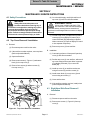
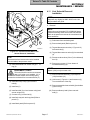
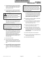
(6) On units which apply, carefully break front of
top cover (3) loose from silicone sealant.
4.1 Safety Precautions
WARNING
EQUIPMENT ALERT
Always disconnect the power cord
from the outlet before removing any of
the sterilizer covers/panels or making any repairs
to prevent the possibility of electrical shock.
Also, drain the sterilizer to prevent spills during
repairs. Failure to comply with these instructions
could result in serious personal injury or death.
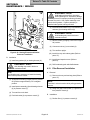
Lift top cover carefully and slowly. Ribbon connector is still connected to display
PC board and any excess pressure exerted on it
could result in a damaged ribbon connector or display
PC board.
(7) Lift rear of top cover (3) and disconnect ribbon
connector (6) from display PC board (7A) or
control PC board (7B) (depending on whether
ribbon connector (6) is part of display PC board
or is a separate component).
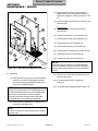
4.2 Top Cover Removal / Installation
A. Removal
(8) Remove top cover (3) from sterilizer.
(1) Disconnect power cord from the outlet.
(2) If the sterilizer contains a printer, remove printer
(Refer to Operation Manual).
B. Installation
(1) Coat mating surfaces of front panel lip and top
cover (3) with silicone sealant.
(3) Open sterilizer door.
(2) Position top cover (3) over sterilizer, with rear of
top cover raised, and connect ribbon connector
(6) to display PC board (7A) or control PC
board (7B).
(4) Remove two screws (1, Figure 4-1) and steam
block (2) from top cover (3).
(5) Remove four screws (4) and two screws (5)
from top cover (3).
(3) Install top cover (3) on sterilizer and secure
using two screws (5) and four screws (4).
(4) Install steam block (2) on top cover (3) and
secure using two screws (1).
7A
6
4
5
(5) Close sterilizer door.
(6) If the sterilizer contains a printer, install printer
(Refer to Operation Manual).
3
4.3 Right Hand Side Panel Removal /
Installation
2
A. Removal
1
(1) Disconnect power cord from the outlet.
7B
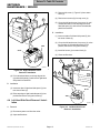
(2) Remove two screws (1, Figure 4-2) from top
cover (2).
MA204802
Figure 4-1. Top Cover Removal / Installation
© Midmark Corporation 2002 SF-1827
Page 4-1
Printed in U.S.A.
Return To Table Of Contents
SECTION IV
MAINTENANCE / SERVICE
1
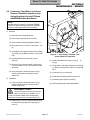
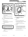
(3) Remove left screw (1, Figure 4-3) from steam
block (2).
2
(4) Remove two screws (3) from top cover (4).
3
(5) Lift up the left hand corner of top cover (4), pull
outward and down on the top edge of the left
hand side panel (5), and remove left hand side
panel from sterilizer.
B. Installation
(1) Insert two tabs of left hand side panel (5) into
two slots of base (6).
(2) Lift up the left hand corner of top cover (4), raise
the top edge of left hand side panel (5) into
position, and secure using two screws (3).
TAB
(3) Install left screw (1) on steam block (2).
SLOT
(4) Close sterilizer door.
3
4
4
2
1
MA2049-01
Figure 4-2. Right Hand Side Panel
Removal / Installation
5
6
(3) Pull outward and down on the top edge of the
right hand side panel (3) and remove right hand
side panel from sterilizer.
B. Installation
(1) Insert two tabs of right hand side panel (3) into
two slots of base (4).
SLOT
(2) Raise top edge of right hand side panel (3) into
position and secure using two screws (1).
TAB
4.4 Left Hand Side Panel Removal / Installation
A. Removal
MA2050-01
Figure 4-3. Left Hand Side Panel
Removal / Installation
(1) Disconnect power cord from the outlet.
(2) Open sterilizer door.
© Midmark Corporation 2002 SF-1827
Page 4-2
Printed in U.S.A.
Return To Table Of Contents
SECTION IV
MAINTENANCE / SERVICE
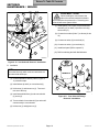
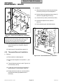
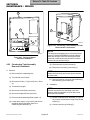
4.5 Back Panel Removal / Installation
EQUIPMENT ALERT
A. Removal
Ensure that wires are completely disconnected before attempting to remove back
panel. Failure to do so could result in damage to
sterilizer.
(1) Disconnect power cord from sterilizer.
(2) Remove right hand side panel (Refer to
para 4.3).
NOTE
Units prior to serial number CZ1110/OM1000 have a
fuse holder attached to the back panel. On these
sterilizers, tag and disconnect two wires from the
receptacle and one wire from the fuse holder instead
of performing step 6.
(3) Remove left hand side panel (Refer to
para 4.4).
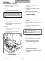
(4) Remove four screws (1, Figure 4-4) from back
panel (2).
(6) On older units, tag and disconnect three wires
(3) from terminals of receptacle (4) and remove
back panel (2) from sterilizer. On newer units,
separate back panel (2) from unit as far as
possible and lay it on its side.
(5) Partially remove back panel (2) by simultaneously pulling downward and outward on back
panel.
5
B. Installation
1
NOTE
Units prior to serial number CZ1110/OM1000 have a
fuse holder attached to the back panel. On these
sterilizers, remove tags and connect two wires to the
receptacle and one wire to the fuse holder instead of
performing step 1.
(1) On older units, remove tags and connect three
wires (3) to terminals of receptacle (4).
FLAP
(2) Position flap of back panel (2) behind top cover
(5) and secure back panel in place using four
screws (1).
4
(3) Install left hand side panel (Refer to para 4.4).
(4) Install right hand side panel (Refer to para 4.3).
3
4.6 Base Inspection Cover Removal /
Installation
2
A. Removal
(1) Disconnect power cord from outlet.
MA2051-01
(2) Drain water from condensing tank.
Figure 4-4. Back Panel Removal / Installation
(3) Turn sterilizer onto its back.
© Midmark Corporation 2002 SF-1827
Page 4-3
Printed in U.S.A.
Return To Table Of Contents
SECTION IV
MAINTENANCE / SERVICE
(4) Remove two screws (1, Figure 4-5) and base
inspection cover (2) from base (3).
B. Installation
TUBE
HOLE
4
(1) Install base inspection cover (2) on base (3) and
secure using two screws (1).
5
(2) Turn sterilizer upright.
(3) Refill condensing tank with distilled water.
3
1
2
1
2
3
MA2052-01
MA2053-01
Figure 4-5. Base Inspection Cover
Removal / Installation
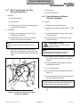
4.7 Bellows Assembly Removal /
Installation
Figure 4-6. Bellows Assembly
Removal / Installation
B. Installation
(1) Connect tubes (1 and 5) to bellows assembly (3).
NOTE
Figure 4-6 shows old-style bellows. The procedure for
the new-style is the same.
(2) Position bellows assembly (3) and insert tube
(5) into tube hole of condensing tank (4).
A. Removal
(3) Connect tube (1) to tee (2).
(1) Remove back panel (Refer to para 4.5).
(4) Install back panel (Refer to para 4.5).
(2) Disconnect tube (1, Figure 4-6) from tee (2).
(3) Pull downward on bellows assembly (3) to
remove bellows assembly from condensing
tank (4).
(4) Loosen and remove tubes (1 and 5) from
bellows assembly (3).
© Midmark Corporation 2002 SF-1827
Page 4-4
Printed in U.S.A.
Return To Table Of Contents
SECTION IV
MAINTENANCE / SERVICE
4.8 Condensing Tank Water Level Sensor
Removal / Installation (Applies only to
Units with old style Control PC Board
with EPROM Version M or Before)
NOTE
3
Units with old style control PC board with EPROM
version N or after or new style control PC board do
not have a condensing tank water level sensor.
6
2
4
A. Removal
7
8
(1) Drain water from condensing tank.
5
(2) Remove back panel (Refer to para 4.5).
1
(3) Remove bellows assembly (Refer to para 4.7).
(4) Disconnect wire (1, Figure 4-7) from termi- nal
(2).
(5) Using Water Level Sensor Wrench to hold fitting
(3), loosen nut (4) (Refer to Table 1-2 for special
tool).
(6) Pull assembled level sensor rod (5) from
fitting (3).
MA2054-01
Figure 4-7. Condensing Tank Water Level
Sensor Removal / Installation
(3) Install assembled level sensor rod (5) in
ting (3).
(7) Remove nut (4), silicone tube (6), and crimp (7)
from level sensor rod (5). Discard silicone tube
and crimp.
fit-
(4) Using Water Level Sensor Wrench to hold fitting
(3), tighten nut (4) (Refer to Table 1-2 for special
tool).
(8) Using vise grips to hold level sensor rod (5),
remove nut (8) and terminal (2) from level
sensor rod.
(5) Connect wire (1) to terminal (2).
(6) Install bellows assembly (Refer to para 4.7).
B. Installation
(7) Install back panel (Refer to para 4.5).
(1) Using vise grips to hold level sensor rod (5),
install terminal (2) on level sensor rod and
secure using nut (8).
(8) Refill condensing tank with distilled water.
EQUIPMENT ALERT
The end of the silicone tube must extend
past nut (4) after nut is installed. If it is
not, the level sensor rod will not function properly
because the terminal will be in contact with nut (4).
(2) Install crimp (7), nut (4), and silicone tube (6) on
level sensor rod (5) and secure by crimping
crimp (7).
© Midmark Corporation 2002 SF-1827
Page 4-5
Printed in U.S.A.
Return To Table Of Contents
SECTION IV
MAINTENANCE / SERVICE
4.9 Temperature Sensor Assembly
Removal / Installation
(3) Install flex guard tubing (3) on three wire
harnesses (1).
A. Removal
(4) Connect three wire harnesses (1) to three
terminals (2).
(1) Remove back panel (Refer to para 4.5).
(5) Install back panel (Refer to para 4.5).
NOTE
4.10
Units with old style control PC board with EPROM
version N or after or new style control PC board will
only have two wire harnesses to disconnect instead
of three.
Pressure Vessel Water Level Sensor
Removal / Installation
A. Removal
(1) Remove back panel (Refer to para 4.5).
(2) Disconnect two / three wire harnesses (1, Figure
4-8) from two / three terminals (2).
(2) Remove wire tray rack and tray plate (Refer to
para (4-17).
(3) Remove flex guard tubing (3) from two / three
wire harnesses (1).
(3) Disconnect wire (1, Figure 4-9) from termi- nal
(2).
(4) Remove temperature sensor assembly (4) from
pressure vessel (5).
(4) Remove nut (3) and terminal (2) from level
sensor rod (4).
B. Installation
(5) Remove nut (5).
(1) Coat threads of temperature sensor assembly
(4) with teflon tape.
EQUIPMENT ALERT
(2) Install temperature sensor assembly (4) in
pressure vessel (5).
Do not try to pull level sensor rod out of
back side of pressure vessel. Doing so
will damage level sensor rod.
(6) Push level sensor rod (4) thru fitting (6) and into
pressure vessel (7) and remove level sensor
rod.
(7) Remove spacer (8) from level sensor rod (4).
2
1
5
(8) Remove silicone tube (9) from fitting (6).
Discard silicone tube (9) and crimp (10).
4
(9) If damaged, remove fitting (6) from pressure
vessel (7).
3
B. Installation
(1) If removed, coat fitting (6) with teflon tape and
install fitting in pressure vessel (7).
(2) Install silicone tube (9) and spacer (8) on level
sensor rod (4).
MA2074-01
Figure 4-8. Temperature Sensor Assembly
Removal / Installation
© Midmark Corporation 2002 SF-1827
Page 4-6
Printed in U.S.A.
Return To Table Of Contents
SECTION IV
MAINTENANCE / SERVICE
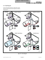
4.11
7
4
NOTE
6
8
Vent Solenoid Removal /
Installation
Steps will vary slightly for M9D / M11D units. Use
this procedure as a guide.
A. Removal
9
NOTE
Units prior to serial number CZ1110/OM1000 have a
manifold assembly which secures the vent solenoid.
Refer to the parts list to remove the vent solenoid on
these sterilizers.
2
10
(1) Drain water from condensing tank.
5
3
(2) Remove back panel (Refer to para 4.5).
1
MA2055-01
Figure 4-9. Pressure Vessel Water Level
Sensor Removal / Installation
(4) Tag and disconnect two wires (2) from terminals
(4).
NOTE
(5) Disconnect three tubes (5 thru 7) from elbows (8
thru 10).
The assembled level sensor rod must be installed
from the inside of the pressure vessel.
(3) Install assembled level sensor rod (4) in
ting (6).
(3) Tag and disconnect two wires (1, Figure 4-10)
from terminals (3).
(6) Remove two screws (11) from bottom of
manifold assembly (12).
fit-
NOTE
EQUIPMENT ALERT
Spacer (12A) is only on newer units.
The end of the silicone tube must extend
past nut (5) after nut is installed. If it is
not, the level sensor rod will not function properly
because the terminal will be in contact with nut (5).
(7) Remove manifold assembly (12) and spacer
(12A) from base (13).
(8) Hold screw (1, Figure 4-11) and loosen nut (2).
Turn terminals out of the way.
(4) Install and crimp crimp (10) on silicone
tube (9).
(9) Remove assembled vent solenoid (3) and elbow
(4) from tee (5).
(5) Install nut (5).
(6) Install terminal (2) on level sensor rod (4) and
secure using nut (3).
(7) Connect wire (1) to terminal (2).
(10) Remove elbows (4 and 6) from vent solenoid (3).
(8) Install wire tray rack and tray plate (Refer to
para 4.17).
(9) Install back panel (Refer to para 4.5).
© Midmark Corporation 2002 SF-1827
Page 4-7
Printed in U.S.A.
Return To Table Of Contents
SECTION IV
MAINTENANCE / SERVICE
EQUIPMENT ALERT
12
3
When installing the vent solenoid, the
side of the solenoid marked IN needs to
be connected to the pressure line. Reversing vent
solenoid will cause system failure.
7
1
10
(7) Install spacer (12A, Figure 4-10) and manifold
assembly (12) on base (13) and secure using
two screws (11).
6
5
9
(8) Connect three tubes (5 thru 7) to elbows (8 thru
10).
(9) Connect two wires (2) to terminals (4).
2
8
(10) Connect two wires (1) to terminals (3).
4
12A
13
(11) Install back panel (Refer to para 4.5).
(12) Refill condensing tank with distilled water.
11
MA2056-02
Figure 4-10. Vent Solenoid Removal / Installation
B. Installation
1
2
6
NOTE
The end of elbow (6) which receives a tube does not
get coated with teflon tape.
TERMINALS
(1) Coat the threads of elbows (4 and 6, Figure 411) with teflon tape.
(2) Install elbows (4 and 6) on vent solenoid (3).
3
5
(3) Hold screw (1) and loosen nut (2). Turn terminals out of the way.
4
MA205701
(4) Install assembled elbow (4) and vent solenoid
(3) on tee (5).
Figure 4-11. Vent Solenoid Fittings
Removal / Installation
(5) Turn terminals of vent solenoid (3) so wires will
connect easily to vent solenoid.
(6) Hold screw (1) and tighten nut (2).
© Midmark Corporation 2002 SF-1827
Page 4-8
Printed in U.S.A.
Return To Table Of Contents
SECTION IV
MAINTENANCE / SERVICE
4.12
Fill Solenoid Removal / Installation
NOTE
Spacer (12A) is only on newer units.
NOTE
Steps will vary slightly for M9D / M11D units. Use
this procedure as a guide.
(7) Remove manifold assembly (12) and spacer
(12A) from base (13).
A. Removal
(8) Hold screw (1, Figure 4-13) and loosen nut (2).
Turn terminals out of the way.
NOTE
(9) Remove assembled vent solenoid (3) and elbow
(4) from tee (5).
Units prior to serial number CZ1110/OM1000 have a
manifold assembly which secures the fill solenoid.
Refer to the parts list to remove the fill solenoid on
these sterilizers.
(10) Remove elbow (6) and tee (5) from fill
solenoid (7).
(1) Drain water from condensing tank.
(11) Remove elbow (8) from fill solenoid (7).
(2) Remove back panel (Refer to para 4.5).
B. Installation
(3) Tag and disconnect two wires (1, Figure 4-12)
from terminals (3).
(1) Coat threads of tee (5, Figure 4-13) and elbows
(6 and 8) with teflon tape.
(4) Tag and disconnect two wires (2) from
terminals (4).
(2) Install elbow (8) on fill solenoid (7).
(5) Disconnect three tubes (5 thru 7) from elbows (8
thru 10).
(3) Install elbow (6) and tee (5) on fill solenoid (7).
(6) Remove two screws (11) from bottom of
manifold assembly (12).
(4) Loosen nut (9). Turn terminals of fill solenoid
(7) so wires will connect easily to fill solenoid.
Tighten nut (9).
12
3
(5) Coat threads of elbow (4) with teflon tape.
7
1
9
7
8
10
1
6
5
2
TERMINALS
9
2
8
6
4
12A
13
5
4
3
MA205801
11
Figure 4-13. Fill Solenoid Fittings
Removal / Installation
MA2056-02
Figure 4-12. Fill Solenoid Removal / Installation
© Midmark Corporation 2002 SF-1827
Page 4-9
Printed in U.S.A.
Return To Table Of Contents
SECTION IV
MAINTENANCE / SERVICE
(6) Hold screw (1) and loosen nut (2). Turn terminals out of the way.
(4) Tag and disconnect two wires (5) from terminals
(6).
(7) Install assembled elbow (4) and vent solenoid
(3) on tee (5).
(5) Tag and disconnect two wires (7) from
terminals (8).
(8) Turn terminals of vent solenoid (3) so wires will
connect easily to vent solenoid.
(6) Disconnect ribbon connector (9) from connector (10).
(9) Hold screw (1) and tighten nut (2).
(7) Tag and disconnect neutral wire (11) from
terminal (12).
EQUIPMENT ALERT
(8) Tag and disconnect hot wire (13) from termi- nal
(14).
When installing the vent solenoid and the
fill solenoid, the side of the solenoids
marked "IN" need to be connected to the pressure
lines. Reversing solenoids will cause system failure.
(9) Disconnect printer cable (15) from connec- tor
(16).
(10) Install spacer (12A, Figure 4-12) and manifold
assembly (12) on base (13) and secure using
two screws (11).
(10) Disconnect door switch harness (17) from
connector (18).
(11) Connect three tubes (5 thru 7) to elbows (8
thru 10).
M9 / M11 only
(11) Tag and disconnect two wires (19) from pulse
solenoid terminals (20).
(12) Connect two wires (2) to terminals (4).
(12) Disconnect heater element wire (21) from
connector (22).
(13) Connect two wires (1) to terminals (3).
(14) Install back panel (Refer to para 4.5).
(15) Refill condensing tank with distilled water.
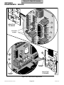
4.13
NOTE
Positions of locknuts (1) and screws (2) are reversed
on newer units.
(13) Remove two locknuts (1, Figure 4-15), screws
(2), and control PC board (3) and control PC
board bracket (4) as an assembly from
base (5).
Control PC Board Removal /
Installation
A. Removal
(1) Remove right hand side panel (Refer to
para 4.3).
(2) Disconnect pressure tube (1, Figure 4-14) from
pressure sensor (2).
NOTE
Units prior to serial number CZ1110/OM1000 have the
ground wire attached to the control PC board bracket.
When nut (6), starwasher (7), and screw (8) are
removed, ground wire will also be removed.
(14) Remove nut (6), starwasher (7), and screw (8)
from control PC board bracket (4).
NOTE
Units with old style control PC board with EPROM
version N or after or new style control PC board will
only have two wire harnesses (3) to disconnect
instead of three.
(15) Turn three standoff screws (9) 1/4 turn in the
counter-clockwise direction and remove control
PC board (3) and insulator (10) from control PC
board bracket (4).
(3) Disconnect two / three wire harnesses (3) from
two / three connectors (4).
© Midmark Corporation 2002 SF-1827
Page 4-10
Printed in U.S.A.
Return To Table Of Contents
SECTION IV
MAINTENANCE / SERVICE
OLD STYLE
PC BOARD
10
18
17
9
20
19
2
1
16
15
3
22
4
21
14
13
12
11
8
5
6
7
10
17
20
9
2
19
1
16
18
NEW STYLE
PC BOARD
15
3
21
4
13
22
11
14
12
8
6
5
7
MA207505
Figure 4-14. Control PC Board Connections
© Midmark Corporation 2002 SF-1827
Page 4-11
Printed in U.S.A.
Return To Table Of Contents
SECTION IV
MAINTENANCE / SERVICE
(3) Install control PC board (3) and control PC
board bracket (4) as an assembly on base (5)
and secure using two screws (2) and lock- nuts
(1).
9
10
(4) Connect heater element wire (21, Figure 4-14) to
connector (22).
M9 / M11 only
(5) Connect two wires (19) on pulse solenoid
terminals (20).
4
(6) Connect wire harness (17) to connector (18).
2
6
(7) Connect printer cable (15) to connector (16).
(8) Connect hot wire (13) to terminal (14).
(9) Connect neutral wire (11) to terminal (12).
7
(10) Connect ribbon connector (9) to connec tor (10).
3
(11) Connect two wires (7) to terminals (8).
8
(12) Connect two wires (5) to terminals (6).
5
1
NOTE
MA2073-01
Figure 4-15. Control PC Board Removal / Installation
Units with old style control PC board with EPROM
version N or after or new style control PC board will
only have two wire harnesses (3) to connect instead
of three.
B. Installation
(13) Connect two / three wire harnesses (3) to two /
three connectors (4).
(1) Install insulator (10, Figure 4-15) and control PC
board (3) on control PC board bracket (4) and
secure by turning three standoff screws (9) 1/4
turn in the clockwise direction.
(14) Connect pressure tube (1) to pressure
sensor (2).
(15) Install right hand side panel (Refer to para 4.3).
NOTE
Units prior to serial number CZ1110/OM1000 have the
ground wire attached to the control PC board bracket.
When nut (6), starwasher (7), and screw (8) are
removed, ground wire will also be removed. Make
sure ground wire is re-installed upon installation.
(2) Install screw (8), starwasher (7), and nut (6) on
control PC board bracket (4).
NOTE
Positions of locknuts (1) and screws (2) are reversed
on newer units.
© Midmark Corporation 2002 SF-1827
Page 4-12
Printed in U.S.A.
Return To Table Of Contents
SECTION IV
MAINTENANCE / SERVICE
4.14
Door Switch Removal / Installation
B. Installation
(1) Position door switch (5) in door switch
bracket (4).
A. Removal
NOTE
(2) Using 3/32 in. punch, install two roll pins (3) in
door switch bracket (4) (Refer to Table 1-2 for
special tool).
Units prior to serial number CZ1110/OM1000 have a
different switch weldment. Since this procedure
tampers with the pressure vessel integrity, it should
not be attempted until a Midmark service representative has been contacted.
(3) Connect wire harness (1) to connector (2).
(4) Install right hand side panel (Refer to
para 4.3).
(1) Open sterilizer door.
(2) Remove right hand side panel (Refer to
4.3).
para
(5) Close sterilizer door.
(3) Disconnect wire harness (1, Figure 4-16) from
connector (2).
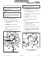
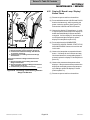
4.15
(4) Using 3/32 in. punch, remove two roll pins (3)
from door switch bracket (4) (Refer to Table 1-2
for special tool).
A. Removal
(1) Remove control PC board (Refer to para 4.13).
(5) Remove door switch (5) from door switch
bracket (4).
2
Pulse Solenoid Removal /
Installation (M9 / M11 only)
(2) Remove two screws (1, Figure 4-17) from pulse
solenoid (2).
(3) Remove nut (3) and shoulder screw (4), and
then remove pulse solenoid (2) and latch lever
(5) as an assembly from pressure vessel
bracket (6).
1
(4) Using 3/32 in. punch, remove roll pin (7) and
latch lever (5) from plunger of pulse solenoid (2)
(Refer to Table 1-2 for special tool).
B. Installation
(1) Using 3/32 in. punch, install latch lever (5) on
plunger of pulse solenoid (2) and secure using
roll pin (7) (Refer to Table 1-2 for special tool).
(2) Coat shoulder screw (4) with Loctite 271.
(3) Install latch lever (5) and pulse solenoid (2) as
an assembly on pressure vessel bracket (6).
Secure using shoulder screw (4) and nut (3).
5
4
3
MA2059-02
Figure 4-16. Door Switch Removal / Installation
© Midmark Corporation 2002 SF-1827
Page 4-13
Printed in U.S.A.
Return To Table Of Contents
SECTION IV
MAINTENANCE / SERVICE
B. Installation
(1) Slide thermostat (8) into bracket (6) and rotate
terminals (3 and 4) to a horizontal position.
PLUNGER
4
5
(2) Position bracket (6) against pressure vessel (7)
and secure by tightening two nuts (5).
3
(3) Connect wires (1 and 2) to terminals (3 and 4).
(4) Install base inspection cover (Refer to
para 4.6).
(5) Refill condensing tank with distilled water.
7
1
8
2
6
1
4
MA2060-01
Figure 4-17. Pulse Solenoid Removal / Installation
3
2
NOTE
The holes for the two screws (1) are oblong. Install
screws at the top of each hole first, then adjust
downward as necessary if door will not open.
7
(4) Position pulse solenoid (2) on pressure vessel
bracket (6) and secure in position using two
screws (1).
6
5
(5) Install control PC board (Refer to para 4.13).
4.16
Thermostat Removal / Installation
MA2062-01
A. Removal
Figure 4-18. Thermostat Removal / Installation
(1) Drain water from condensing tank.
(2) Remove base inspection cover (Refer to
4.6).
para
(3) Tag and disconnect wires (1 and 2, Figure 4-18)
from terminals (3 and 4).
(4) Loosen two nuts (5) and pull top of bracket (6)
approximately 1 in. from pressure vessel (7).
(5) Rotate terminals (3 and 4) to a vertical position
and slide thermostat (8) upward and out of
bracket (6).
© Midmark Corporation 2002 SF-1827
Page 4-14
Printed in U.S.A.
Return To Table Of Contents
SECTION IV
MAINTENANCE / SERVICE
4.17
(4) Install trays.
Wire Tray Rack and Tray Plate
Removal / Installation
(5) Close sterilizer door.
A. Removal
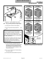
4.18
(1) Open sterilizer door.
(2) Remove trays.
Heating Element and Gasket
Removal / Installation
A. Removal
(3) Pull wire tray rack (1, Figure 4-19) and tray plate
(2) from pressure vessel (3).
(1) Drain water from condensing tank.
(2) Remove base inspection cover (Refer to
4.6).
B. Installation
para
(1) Position two rear posts of wire tray rack (1) in
rack holes of tray plate (2).
(3) Tag and disconnect two wires (1, Figure 4-20)
from terminals (2).
(2) Hold front end of wire tray rack (1) at approximately a 30° angle from tray plate (2).
(4) Remove two nuts (3), lock washers (4), and
brass washers (5).
NOTE
EQUIPMENT ALERT
If wire tray rack is not raised, installation is very
difficult.
Over bending may result in broken or
cracked terminals.
(3) Insert rear end of wire tray rack (1) and tray
plate (2) as an assembly in pressure vessel (3).
Push wire tray rack and tray plate as far as they
will go.
NOTE
The following step is necessary to remove the
heating element from the pressure vessel.
(5) Straighten terminals (2) slightly from the present
90° position to approximately a 10° straighter
position.
(6) Remove bracket (6) from pressure vessel (7)
and position out-of-way.
1
2
(7) Turn sterilizer upright.
(8) Remove wire tray rack and tray plate (Refer to
para 4.17).
(9) Remove heating element (8) and spacer assembly (9) from pressure vessel (7).
NOTE
Perform the following step only if the heating element
is not being replaced, but damaged gaskets are.
3
30°
HOLE
(10) Remove two gaskets (10) from heating ele-ment
(8).
MA2047-01
Figure 4-19. Wire Tray Rack and Tray Plate
Removal / Installation
© Midmark Corporation 2002 SF-1827
Page 4-15
Printed in U.S.A.
Return To Table Of Contents
SECTION IV
MAINTENANCE / SERVICE
EQUIPMENT ALERT
Hold heating element firmly in position
while tightening nuts. Otherwise, damage
to heating element or improper positioning of heating
element may result. Also, spacer assembly must
remain above gaskets. If spacer assembly is
installed under gasket, leaking will result.
7
9
2
(6) Install two brass washers (5), lock washers (4),
and nuts (3) on heating element (8).
8
6
10
EQUIPMENT ALERT
4
Over bending may result in broken or
cracked terminals.
3
(7) Bend terminals (2) slightly, back to their original
90° position.
5
1
(8) Connect two wires (1) to terminals (2).
MA2061-01
(9) Turn sterilizer upright.
Figure 4-20. Heating Element and Gasket
Removal / Installation
(10) Install wire tray rack and tray plate (Refer to
para 4.17).
B. Installation
(11) Install base inspection cover (Refer to
para 4.6).
(1) Install two gaskets (10) on heating element (8).
EQUIPMENT ALERT
(12) Refill condensing tank with distilled water.
Over bending may result in broken or
cracked terminals.
4.19
NOTE
Filter Removal / Installation
A. Removal
The following step is necessary to install the heating
element in the pressure vessel.
(1) Remove wire tray rack and tray plate (Refer to
para 4.17).
(2) Straighten terminals (2) slightly from the present
90° position to approximately a 10° straighter
position.
NOTE
Turn filter in a circular motion while pulling upward to
remove.
(3) Install spacer assembly (9) and heating element
(8) in pressure vessel (7).
(2) Using vise grips, remove filter (1, Figure 4-21)
from pressure vessel (2).
(4) Turn sterilizer on its back.
B. Installation
(5) Position bracket (6) on pressure vessel (7).
(1) Position filter (1) in pressure vessel (2).
© Midmark Corporation 2002 SF-1827
Page 4-16
Printed in U.S.A.
Return To Table Of Contents
SECTION IV
MAINTENANCE / SERVICE
3
GROOVE
1
SLOT
2
2
MA2063-01
Figure 4-21. Filter Removal / Installation
FLAP
(2) Using rubber hammer, tap filter (1) lightly into
pressure vessel (2).
MA2064-01
Figure 4-22. Door Gaskets Removal / Installation
(3) Install wire tray rack and tray plate (Refer to
para 4.17).
4.20
1
4.21
Door Gaskets Removal / Installation
Display PC Board Removal /
Installation
A. Removal
A. Removal
(1) Remove top cover (Refer to para 4.2).
(1) Open sterilizer door.
(2) Remove six screws (1, Figure 4-23) and display
PC board (2) from top cover (3).
(2) Remove dam gasket (1, Figure 4-22) and door
gasket (2) from door (3).
(3) If damaged, remove gasket (4) from top
cover (3).
B. Installation
(1) Install door gasket (2) in groove in door (3).
B. Installation
NOTE
(1) If removed, install new gasket (4) by peeling
protective backing off of gasket and pressing
gasket firmly into position on top cover (3).
Some models may have two mounting pins on door
instead of flap. Secure dam gasket by pressing onto
mounting pins.
(2) Install dam gasket (1) by inserting bottom edge
of dam gasket in slot of door gasket (2) and
tucking top edge of dam gasket under flap of
door (3).
(2) Install display PC board (2) on top cover (3) and
secure using six screws (1).
(3) Install top cover (Refer to para 4.2).
(3) Close sterilizer door.
© Midmark Corporation 2002 SF-1827
Page 4-17
Printed in U.S.A.
Return To Table Of Contents
SECTION IV
MAINTENANCE / SERVICE
3
1
2
2
1
4
MA2066-01
Figure 4-24. Condensing Tank Assembly Fill Tube
Disconnection / Connection
NOTE
MA2065-01
Figure 4-23. Display PC Board
Removal / Installation
4.22
The following step applies only to units with old style
control PC board with EPROM version M or before.
Units with old style control PC board with EPROM
version N or after or new style control PC board do
not have wire (4) and terminal (5).
(9) Disconnect wire (4) from terminal (5).
Condensing Tank Assembly
Removal / Installation
(10) Disconnect vent tube (6) from fitting (7).
A. Removal
NOTE
Positions of locknut (9) and screws (8) are reversed
on newer units.
(1) Drain water from condensing tank.
(2) Turn sterilizer onto its back.
(11) Remove screw (8), locknut (9), and condensing
tank assembly (3) from base (10).
(3) Disconnect fill tube (1, Figure 4-24) from elbow
(2).
B. Installation
(4) Turn sterilizer upright.
NOTE
Fill tube must be lined up with fitting at this time
because it will be impossible to line up after screw
and locknut are installed.
(5) Remove top cover (Refer to para 4.2).
(6) Remove back panel (Refer to para 4.5).
(7) Remove bellows assembly (Refer to para 4.7).
(8) Loosen hose clamp (1, Figure 4-25) and remove
sight/drain tube (2) and hose clamp from
condensing tank assembly (3).
© Midmark Corporation 2002 SF-1827
Page 4-18
(1) Position condensing tank assembly (3, Figure 425) on base (10) and secure using screw (8) and
locknut (9).
(2) Connect vent tube (6) to fitting (7).
Printed in U.S.A.
Return To Table Of Contents
SECTION IV
MAINTENANCE / SERVICE
NOTE
4.23
The following step applies only to units with old style
control PC board with EPROM version M or before.
Units with old style control PC board with EPROM
version N or after or new style control PC board do
not have wire (4) and terminal (5).
Pressure Relief Valve Removal /
Installation
A. Removal
(1) Remove condensing tank assembly (Refer to
para 4.22).
(3) Connect wire (4) to terminal (5).
(2) Disconnect tube (1, Figure 4-26) from
elbow (2).
(4) Install hose clamp (1) and sight/drain tube (2) on
condensing tank assembly (3). Tighten hose
clamp.
(3) Remove elbow (2) from pressure relief
(3).
valve
(5) Install bellows assembly (Refer to para 4.7).
(4) Remove pressure relief valve (3) from pressure
vessel (4).
(6) Install back panel (Refer to para 4.5).
(7) Install top cover (Refer to para 4.2).
B. Installation
(8) Turn sterilizer onto its side.
(1) Coat threads of pressure relief valve (3) and
elbow (2) with teflon tape.
(9) Connect fill tube (1, Figure 4-24) to elbow (2).
(10) Turn sterilizer upright.
(2) Install pressure relief valve (3) in pressure
vessel (4).
(11) Refill condensing tank with distilled water.
(3) Install elbow (2) on pressure relief valve (3).
(4) Connect tube (1) to elbow (2).
7
6
(5) Install condensing tank assembly (Refer to
para 4.22).
5
8
4
2
3
2
10
4
1
3
9
MA2067-01
1
Figure 4-25. Condensing Tank Assembly
Removal / Installation
MA2068-01
Figure 4-26. Pressure Relief Valve
Removal / Installation
© Midmark Corporation 2002 SF-1827
Page 4-19
Printed in U.S.A.
Return To Table Of Contents
SECTION IV
MAINTENANCE / SERVICE
4.24
Pressure / Temperature Potentiometers Adjustments
NOTE
After the following step is performed, the display PC
board lamps will individually illuminate and then
extinguish one at a time in a left to right sequence.
When all the lamps have illuminated and extinguished, proceed with step 4.
EQUIPMENT ALERT
The pressure zero, pressure range, and
temperature potentiometers cannot be
adjusted separately. If one potentiometer needs
adjusted, then the entire potentiometer adjustment
procedure must be performed, and it must be performed in the proper sequence as follows:
(3) Press and hold down the LIQUIDS and PACKS
buttons simultaneously while connecting the
power cord to the sterilizer (See Figure 4-27).
Release the LIQUIDS and PACKS buttons.
(1) Remove right hand side panel.
NOTE
(2) Open sterilizer door.
When each button is pressed, its corresponding lamp
will illuminate and stay illuminated. Also, after the
following step, the PRESSURE (PSI) display will
display the pressure that the control PC board is
reading and the TEMP (°F) / TIME (MIN: SECONDS)
display will display the temperature that the control
PC board is reading. When each button has been
pushed, proceed with step 5.
DANGER
The following steps require the sterilizer to be plugged in to power while the
adjustment is being performed. Do not touch any
components except for the adjusting screw of the
potentiometer. Failure to comply with these
instructions could result in an electrical shock,
which could result in severe personal injury or
death.
(4) Press and release the UNWRAPPED,
POUCHES, LIQUIDS, PACKS, START, STOP,
AND ON/STANDBY buttons one at a time and
in this order.
TEMP / TIME DISPLAY
LAMP
LAMP
TEMP (°F) \ TIME (MIN : SECONDS)
PRESSURE (PSI)
FILLING
STERILIZING
DRYING
COMPLETE
WATER LOW
DOOR AJAR
ERROR
UNWRAPPED
POUCHES
LIQUIDS
PACKS
START
STOP
ON/STANDBY
PRESSURE
DISPLAY
UNWRAPPED
BUTTON
POUCHES
BUTTON
ON / STANDBY
BUTTON
PACKS
BUTTON
START
BUTTON
STOP
BUTTON
LIQUIDS
BUTTON
MA207701
Figure 4-27. Display PC Board Lamp / Display / Button Check
(M9 / M11 shown)
© Midmark Corporation 2002 SF-1827
Page 4-20
Printed in U.S.A.
Return To Table Of Contents
SECTION IV
MAINTENANCE / SERVICE
(5) Turn adjusting screw of pressure zero potentiometer (1, Figure 4-28) in the counter-clockwise
direction until the PRESSURE (PSI) display
reads 0.0 psi (0.0 kPa).
(6) Turn adjusting screw of pressure zero potentiometer (1) in the clockwise direction until the
PRESSURE (PSI) display reads 0.1 psi (1 kPa).
NOTE
Turning the adjusting screw of the pressure range
potentiometer in the clockwise direction raises the
sterilizer pressure reading while turning the adjusting
screw in the counter-clockwise direction lowers the
sterilizer pressure reading.
CAUTION
The multimeter leads must be connected
exactly as shown in the illustration.
Connecting a lead to the wrong side of the resistor or
wrong pin of the chip will result in an incorrect
adjustment.
(7) Set the multimeter to read VDC at least the 5
Volts range. Connect the red lead of a multimeter to Test Point (A) and the black lead of a
multimeter to Test Point (B).
NOTE
(12) Turn the adjusting screw of the pressure range
potentiometer (2, Figure 4-28) in the clockwise
or counter-clockwise direction until the reading
on the PRESSURE (PSI) display matches the
reading of the Pressure Gauge Test Harness
within a tolerance of ±0.5 psi (3.5 kPa).
(13) Recheck the multimeter reading. It should still
read 2.550 VDC ±0.001 VDC.
(14) Press the STOP button to end the test/calibration cycle and allow the sterilizer to vent and
open its door (See Figure 4-27).
(15) Disconnect the leads of the multimeter from
Test Points (A and B, Figure 4-28).
In the following step, if the digital multimeter being
used has only three digits, adjust to a reading of 2.54
VDC and then adjust and set to where the reading
just changes to 2.55 VDC.
(8) The multimeter should read 2.550 VDC ±0.001
VDC. If multimeter reading is not 2.550 VDC
±0.001 VDC, adjust the adjusting screw of the
temperature potentiometer (3) in a clockwise
direction to lower the voltage setting or a
counter-clockwise direction to raise the voltage
setting until the multimeter reading is 2.550
VDC ±0.001 VDC.
(16) Disconnect the power cord from the sterilizer
and then repeat steps 3 and 4 of this procedure.
The reading should read 0.1 psi (1 kPa) with the
sterilizer door open. If not, repeat steps 5 and 6
of this procedure.
(17) Disconnect the power cord from sterilizer.
(18) Disconnect Pressure Gauge Test Harness from
sterilizer (See Figure 4-29).
(19) Install right hand side panel.
(9) Close the sterilizer door.
(10) Connect Pressure Gauge Test Harness to
sterilizer (See Figure 4-29) (Refer to the sterilizer Service and Parts Manual for this special
tool).
(11) Press the START button to start a test/calibration cycle and wait until the temperature on the
TEMP (°F) / TIME (MIN: SECONDS) display
reaches 272 - 273°F (133-134°C) (See Figure 427).
© Midmark Corporation 2002 SF-1827
Page 4-21
Printed in U.S.A.
Return To Table Of Contents
SECTION IV
MAINTENANCE / SERVICE
O
F
F
1 2 3 4
A
R3
2
U1
NEW STYLE
PC BOARD
3
2
B
ADJUSTING
SCREWS
2
1
3
1
B
A
3
ADJUSTING
SCREWS
OLD STYLE
PC BOARD
ADJUSTING
SCREW
2
MA407700
Figure 4-28. Potentiometer Adjustments
© Midmark Corporation 2002 SF-1827
Page 4-22
Printed in U.S.A.
Return To Table Of Contents
SECTION IV
MAINTENANCE / SERVICE
4.25
2
(1) Disconnect power cord from the sterilizer.
1
TUBE
Display PC Board Lamp / Display /
Button Check
(2) Press and hold down the LIQUIDS and PACKS
buttons simultaneously, while connecting the
power cord to the sterilizer (See Figure 4-30).
Release the LIQUIDS and PACKS buttons.
(3) Observe the display PC board lamps. In a left
to right sequence, each lamp on the display PC
board should individually illuminate and then
extinguish. If all the display PC board lamps do
not illuminate and then extinguish, replace
display PC board (Refer to para 4.21).
FITTING
PRESSURE GAUGE
TEST HARNESS
(4) Press and release the UNWRAPPED,
POUCHES, LIQUIDS, PACKS, START, STOP,
AND ON/STANDBY buttons one at a time and
in this order.
To connect Pressure Gauge Test Harness to sterilizer:
1. Disconnect tube (1) from pressure sensor (2).
2. Connect tube of Pressure Guage Test Harness
to pressure sensor (2).
3. Connect tube (1) to fitting of Pressure Guage
Test Harness.
(5) Observe the lamps that correspond with each
button. If all lamps do not illuminate and stay
illuminated when their corresponding button is
pressed, replace the display PC board (Refer to
para 4.21).
To disconnect Pressure Gauge Test Harness from
sterilizer:
1. Disconnect tube (1) from fitting of Pressure
Guage Test Harness.
2. Disconnect tube of Pressure Guage Test Harness
from pressure sensor (2).
3. Connect tube (1) to pressure sensor (2). MA2070-01
Figure 4-29. Connecting / Disconnecting Pressure
Gauge Test Harness
(6) Observe the pressure and temperature/time
displays. If the pressure and temperature/time
displays do not display pressure and temperature readings, replace the display PC board
(Refer to para 4.21).
(7) Disconnect power cord from the sterilizer.
© Midmark Corporation 2002 SF-1827
Page 4-23
Printed in U.S.A.
Return To Table Of Contents
SECTION IV
MAINTENANCE / SERVICE
TEMP / TIME DISPLAY
LAMP
LAMP
TEMP (°F) \ TIME (MIN : SECONDS)
PRESSURE (PSI)
FILLING
STERILIZING
DRYING
COMPLETE
WATER LOW
DOOR AJAR
ERROR
UNWRAPPED
POUCHES
LIQUIDS
PACKS
START
STOP
ON/STANDBY
PRESSURE
DISPLAY
UNWRAPPED
BUTTON
POUCHES
BUTTON
ON / STANDBY
BUTTON
PACKS
BUTTON
START
BUTTON
STOP
BUTTON
LIQUIDS
BUTTON
MA207701
Figure 4-30. Display PC Board Lamp / Display / Button Check (M9 / M11 shown)
4.26
(4) If excessive force was required to open pressure relief valve (2), replace the pressure relief
valve (Refer to para 4.23).
Pressure Relief Valve Check
(1) Remove the top inspection cover (1,
Figure 4-31).
NOTE
If the pressure relief valve does not close completely
when the wire ring is released, pull the wire ring again
and release it quickly so the valve snaps back into
position. Do this until the valve seats properly.
WARNING
Refer to the operator manual for
complete instructions on operating the
sterilizer. Failure to do so could result in severe
personal injury.
(5) Release wire ring of pressure relief valve (2).
The steam should vent out of the pressure relief
valve until the wire ring is released. When the
wire ring is released, the valve should seat,
stopping the release of steam.
(2) Select the UNWRAPPED cycle and start the
cycle.
DANGER
Pressure Relief Valve will be hot.
Use a screwdriver or rod to pull the
wire ring. Do not pull the wire ring with bare
hands or burns will result. Steam will be vented
from under the rear of the sterilizer. To keep from
being burned, place a steam barrier (a rolled up
towel) around the bottom of the sterilizer.
(6) If the pressure relief valve (2) will not re-seat
properly, replace the pressure relief valve (Refer
to para 4.23).
(7) Install top inspection cover (1).
(3) When the “heat up” portion of the cycle is
complete and the elapsed time is being counted
down on the display PC board, pull on wire ring
of pressure relief valve (2) with a screwdriver.
© Midmark Corporation 2002 SF-1827
Page 4-24
Printed in U.S.A.
Return To Table Of Contents
SECTION IV
MAINTENANCE / SERVICE
SETTING #1
REPEAT INTERVAL
1
SETTING #3
REPEAT INTERVAL
WIRE
RING
O
F
F
O
F
F
1 2 3 4
1 2 3 4
2
#3 SWITCH DEPRESSED
TO RIGHT (ON)
#4 SWITCH DEPRESSED
TO RIGHT (ON)
#3 SWITCH DEPRESSED
TO LEFT (OFF)
#4 SWITCH DEPRESSED
TO LEFT (OFF)
SETTING #2
REPEAT INTERVAL
SETTING #4
REPEAT INTERVAL
MA2072-01
Figure 4-31. Pressure Relief Valve Check
4.27
Dry Cycle Dip Switches Adjustment
There are four repeat interval dip switch settings;
setting #1, setting #2, setting #3, and setting #4. The
unit comes factory set at the repeat interval setting #3. Setting #1 is shortest repeat interval, setting
#2 is longer, setting #3 is longer yet, and setting #4 is
the longest repeat interval.
This procedure only applies to units with a new style
control PC board; units with serial numbers: CZ2457,
DA1005, DB1150, DX1970, DY1139, ES1347,
ET1095, FD-1000, FP1000, FR1000, GB1000 and
OM-9449 thru Present.
#3 SWITCH DEPRESSED
TO LEFT (OFF)
#4 SWITCH DEPRESSED
TO RIGHT (ON)
1 2 3 4
NOTE
O
F
F
para
1 2 3 4
(2) Remove right hand side panel (Refer to
4.3).
O
F
F
(1) Unplug power cord from outlet receptacle.
#3 SWITCH DEPRESSED
TO RIGHT (ON)
#4 SWITCH DEPRESSED
TO LEFT (OFF)
DRY CYCLE
DIP SWITCH
(3) If unit has has been overheating during the
drying cycle and activating the overheat thermostat, determine the current repeat interval dip
switch settings for the unit per Figure 4-32 and
then change the dip switch settings to the next
shortest repeat interval.
MA374000
Figure 4-32. Dry Cycle Dip Switches Adjustment
(4) Run a cycle. Repeat step 3 if overheat thermostat activates again.
(5) Install right hand side panel (Refer to para 4.3).
© Midmark Corporation 2002 SF-1827
Page 4-25
Printed in U.S.A.
Return To Table Of Contents
SECTION IV
MAINTENANCE / SERVICE
4.28
(4) Press and hold STOP & POUCHES buttons
(see Figure 4-33) while plugging in power cord.
M9 / M11 Door Opening Test
NOTE
(5) Press and release all buttons from left to right
across display panel.
This test applies only to units with newer style PC
boards.
(1) Fill chamber with water. [To do this, start any
cycle. After chamber has filled with water, the
Sterilizing LED will illuminate].
(6) Close door. [This will activate all relays in the
sterilizer in sequence. Pulse solenoind should
automatically open door when test cycle is
complete].
(2) Disconnect power cord.
(7) To rerun test, repeat steps 2 thru 6.
(3) Open door.
(8) To verify proper operation, run a complete cycle
when test is complete.
TEMP / TIME DISPLAY
LAMP
LAMP
TEMP (°F) \ TIME (MIN : SECONDS)
PRESSURE (PSI)
FILLING
STERILIZING
DRYING
COMPLETE
WATER LOW
DOOR AJAR
ERROR
UNWRAPPED
POUCHES
LIQUIDS
PACKS
START
STOP
ON/STANDBY
PRESSURE
DISPLAY
UNWRAPPED
BUTTON
POUCHES
BUTTON
ON / STANDBY
BUTTON
PACKS
BUTTON
START
BUTTON
LIQUIDS
BUTTON
STOP
BUTTON
MA207701
Figure 4-33. M9 / M11 Door Opening Test
© Midmark Corporation 2002 SF-1827
Page 4-26
Printed in U.S.A.
Return To Table Of Contents
SECTION V
SCHEMATICS AND DIAGRAMS
SECTION V
SCHEMATICS AND DIAGRAMS
5.1 Wiring Diagrams
Figure 5-1 (sheets 1 thru 3) illustrate the wiring connections for the M9 sterilizer.
Figure 5-3 (sheets 1 thru 3) illustrate the wiring connections for the M11 sterilizer.
Figure 5-2 (sheets 1 & 2) illustrate the wiring connections for the M9D sterilizer.
Figure 5-4 (sheets 1 & 2) illustrate the wiring connections for the M11D sterilizer.
(*) NOTE:
Some Solenoid Coils may be marked
FWR (Full Wave Rectified).
Use the Mohms scale to measure these coils.
If reading is 0.2 Mohms or above, coil is
GOOD. If OL is displayed, coil is BAD
Printer
Printer
Connector
4
5
3
1
1 2 3 4 5
2
PCB/Printer
Harness
(015-0668-00)
Display Panel
PC Board
Temperature
Probe Assembly
Orange (Ground)
Ribbon Cable
Connector
(015-0646-00)
Green (Ground)
Red (Power)
Blue (Busy)
Blue
Black
Door Switch
Level
Sensor Assembly
White (Ground)
N.O.
Black (+5 V.)
Flex Guard
Tubing
(015-0257-02)
Red (V. Out)
White (Data)
Red
Black
Chamber Level
Sensor Harness
(015-0654-00)
Green
Control
PC Panel
Reservoir
Sensor Assembly
Door Pulse
Solenoid
Black
Black
100V Unit 7.90 ohms
120V Unit 14.0 ohms
240V Unit 52.0 ohms
Black
Reservoir
Sensor
Harness
(015-0655-00)
Red
Hot
Red
Neutral
Yellow
Black
Green
Green
PCB/Heater
Harness
(015-0657-00)
Overheat
thermostat
(015-0679-00)
Black
Ground
100V Unit 6.81 to 7.52 ohms
120V Unit 9.77 to 10.80 ohms
240V Unit 40.46 to 44.71 ohms
PCB/AC/Thermostat
Harness (015-0877-00)
Fill Solenoid
Vent Solenoid
100V Unit 375 ohms
120V Unit 400 ohms
240V Unit 1960 ohms
L
G
U
White
Green/Yellow or
Green
Red
100V Unit 137 ohms
120V Unit 140 ohms
240V Unit 818 ohms
Black
Heating Element
(*)
A.C. Connector
Receptacle
Cordset
U.S.A. 015-0640-00
Cont. Europe 015-0688-07
Italian 015-0688-08
Swiss 015-0688-09
United Kingdom 015-0688-10
Australian 015-0688-11
Israeli 015-0688-12
Japanese 015-0363-06
MA246706
Figure 5-1 (Sheet 1 of 3). M9 Wiring Diagram
(Applies To Serial Numbers CZ1000 thru CZ1684, DB1000 thru DB1010, OM1000 thru OM5130,
DX1000 thru DX1170, DA1000 thru DA1001, and DY1000 thru DY1007)
© Midmark Corporation 2002 SF-1827 Rev. 5/03
Page 5-1
Printed in U.S.A.
Return To Table Of Contents
SECTION V
SCHEMATICS AND DIAGRAMS
Printer
Printer
Connector
(*) NOTE:
Some Solenoid Coils may be marked
FWR (Full Wave Rectified).
Use the Mohms scale to measure these coils.
If reading is 0.2 Mohms or above, coil is
GOOD. If OL is displayed, coil is BAD
4
5
3
1
1 2 3 4 5
2
PCB/Printer
Harness
Display Panel
PC Board
Temperature
Probe Assembly
Orange (Ground)
Ribbon Cable
Connector
Green (Ground)
Red (Power)
Blue (Busy)
Blue
Black
Door Switch
Level
Sensor Assembly
White (Ground)
N.O.
Black (+5 V.)
Flex Guard
Tubing
Red (V. Out)
White (Data)
Red
Black
Chamber Level
Sensor Harness
Control
PC Panel
Door Pulse
Solenoid
Black
100V Unit 7.90 ohms
120V Unit 14.0 ohms
240V Unit 52.0 ohms
Black
Hot
Red
Neutral
Yellow
Black
Green
Black
Ground
PCB/Heater
Harness
(*)
Red
Fill Solenoid
Vent Solenoid
100V Unit 137 ohms
120V Unit 140 ohms
240V Unit 818 ohms
100V Unit 375 ohms
120V Unit 400 ohms
240V Unit 1960 ohms
Overheat
thermostat
Black
Heating Element
100V Unit 6.81 to 7.52 ohms
120V Unit 9.77 to 10.80 ohms
240V Unit 40.46 to 44.71 ohms
PCB/AC/Thermostat
Harness (015-0877-00)
L
G
N
White
Green/Yellow
A.C. Connector
Receptacle
Cordset
U.S.A. 015-0640-00
Cont. Europe 015-0688-07
Italian 015-0688-08
Swiss 015-0688-09
United Kingdom 015-0688-10
Australian 015-0688-11
Israeli 015-0688-12
Japanese 015-0363-06
MA246707
Figure 5-1 (Sheet 2 of 3) M9 Wiring Diagram
(Applies To Serial Numbers CZ1685 thru CZ4590, DB1011 thru DB1149, OM5131 thru OM14723,
DX1171 thru DX1969, DA1002 thru DA1004, and DY1008 thru DY1138)
© Midmark Corporation 2002 SF-1827 Rev. 5/03
Page 5-2
Printed in U.S.A.
Return To Table Of Contents
SECTION V
SCHEMATICS AND DIAGRAMS
(*) NOTE:
Some Solenoid Coils may be marked
FWR (Full Wave Rectified).
Use the Mohms scale to measure these coils.
If reading is 0.2 Mohms or above, coil is
GOOD. If OL is displayed, coil is BAD
Printer
Printer
Connector
4
5
3
1
1 2 3 4 5
2
Display Panel
PC Board
Temperature
Probe Assembly
PCB/Printer
Harness
Blue (Busy)
White (Data)
Level
Sensor Assembly
White (Ground)
Flex Guard
Tubing
Green (Ground)
Red (Power)
Black (+5 V.)
Orange (Ground)
Red (V. Out)
Ribbon Cable
Connector
Red
Black
Chamber Level
Sensor Harness
Control
PC Panel
Blue
N.O.
Black
Door Switch
Door Pulse
Solenoid
Red
Black
Red
Hot
Black
Neutral
100V Unit 7.90 ohms
120V Unit 14.0 ohms
240V Unit 52.0 ohms
Black
(*)
Black
Ground
Fill Solenoid
Vent Solenoid
Heating Element
120 V. CORDSET
(U.S.A.)
Black
Black
Green/Yellow
015-1139-00
Cont. Europe 015-0688-07
Italian 015-0688-08
Swiss 015-0688-09
United Kingdom 015-0688-10
Australian 015-0688-11
Israeli 015-0688-12
Japanese 015-0363-06
Overheat
thermostat
015-1138-00
Overheat
thermostat
100V Unit 6.81 to 7.52 ohms
120V Unit 9.77 to 10.80 ohms
240V Unit 40.46 to 44.71 ohms
100V Unit 375 ohms
120V Unit 400 ohms
240V Unit 1960 ohms
Green
PCB/Heater
Harness
Yellow
100V Unit 137 ohms
120V Unit 140 ohms
240V Unit 818 ohms
Green/Yellow
White
White
PCB/AC/Thermostat
Harness
L
G
N
230 V.
Cordset
A.C. Connector
Receptacle
MA376202
Figure 5-1 (Sheet 3 of 3) M9 Wiring Diagram
(Applies To Serial Numbers CZ4591 thru Present, DA1005 thru Present, DB1150 thru Present,
DX1970 thru Present, DY1139 thru Present, FD1000 thru Present, and OM14724 thru Present)
© Midmark Corporation 2002 SF-1827 Rev. 5/03
Page 5-3
Printed in U.S.A.
Return To Table Of Contents
SECTION V
SCHEMATICS AND DIAGRAMS
(*) NOTE:
Some Solenoid Coils may be marked
FWR (Full Wave Rectified).
Use the Mohms scale to measure these coils.
If reading is 0.2 Mohms or above, coil is
GOOD. If OL is displayed, coil is BAD
Printer
Printer
Connector
4
5
3
1
1 2 3 4 5
2
Display Panel
PC Board
Temperature
Probe Assembly
PCB/Printer
Harness
Ribbon Cable
Connector
Blue (Busy)
White (Data)
N.O.
White (Ground)
Red (Power)
Black (+5 V.)
Flex Guard
Tubing
Green (Ground)
Red (V. Out)
Orange (Ground)
Level
Sensor Assembly
Red
Black
Chamber Level
Sensor Harness
Control
PC Panel
Blue
Black
Door Switch
ORANGE
Hot
Neutral
ORANGE
Black
Black
Ground
(*)
Fill Solenoid
Green
PCB/Heater
Harness
Yellow
120V Unit 140 ohms
Vent Solenoid
120V Unit 1170 ohms
Overheat
thermostat
Black
A.C. Connector
Receptacle
L
G
N
White
015-0640-00
Heating Element
Green/Yellow
120V Unit 9.77 to 10.80 ohms
PCB/AC/Thermostat
Harness
MA444601
Figure 5-2 (Sheet 1 of 2) M9D Wiring Diagram
(Applies To Serial Numbers FF1000 thru FF1054, FG1000 thru FG1137)
© Midmark Corporation 2002 SF-1827 Rev. 5/03
Page 5-4
Printed in U.S.A.
Return To Table Of Contents
SECTION V
SCHEMATICS AND DIAGRAMS
(*) NOTE:
Some Solenoid Coils may be marked
FWR (Full Wave Rectified).
Use the Mohms scale to measure these coils.
If reading is 0.2 Mohms or above, coil is
GOOD. If OL is displayed, coil is BAD
Printer
Printer
Connector
4
3
5
1
1 2 3 4 5
2
Display Panel
PC Board
Temperature
Probe Assembly
PCB/Printer
Harness
Red (Power)
Blue (Busy)
White (Data)
Level
Sensor Assembly
White (Ground)
Flex Guard
Tubing
Green (Ground)
Black (+5 V.)
Orange (Ground)
Red (V. Out)
Ribbon Cable
Connector
Red
Black
Chamber Level
Sensor Harness
Control
PC Panel
Blue
N.O.
Black
Door Switch
ORANGE
Hot
Neutral
ORANGE
Black
Black
Ground
(*)
Fill Solenoid
Vent Solenoid
120V Unit 1170 ohms
015-1138-00
Green
PCB/Heater
Harness
Yellow
120V Unit 140 ohms
Overheat
Thermosta
Black
Green/Yellow
Heating Element
120V Unit 9.77 to 10.80 ohms
White
120 V. CORDSET
(U.S.A.)
015-1139-00
MA444501
Figure 5-2 (Sheet 2 of 2) M9D Wiring Diagram
(Applies To Serial Numbers FF1055 thru Present and FG1138 thru Present)
© Midmark Corporation 2002 SF-1827 Rev. 5/03
Page 5-5
Printed in U.S.A.
Return To Table Of Contents
SECTION V
SCHEMATICS AND DIAGRAMS
(*) NOTE:
Some Solenoid Coils may be marked
FWR (Full Wave Rectified).
Use the Mohms scale to measure these coils.
If reading is 0.2 Mohms or above, coil is
GOOD. If OL is displayed, coil is BAD
Printer
Printer
Connector
4
5
3
1
1 2 3 4 5
2
PCB/Printer
Harness
Display Panel
PC Board
Temperature
Probe Assembly
Orange (Ground)
Ribbon Cable
Connector
Green (Ground)
Red (Power)
Blue (Busy)
Blue
Black
Door Switch
Level
Sensor Assembly
White (Ground)
N.O.
Black (+5 V.)
Flex Guard
Tubing
Red (V. Out)
White (Data)
Red
Black
Chamber Level
Sensor Harness
Control
PC Panel
Door Pulse
Solenoid
Black
120V Unit 11.2 (+/- 1) ohms
240V Unit 45.0 (+/- 4) ohms
Black
Hot
Red
Neutral
Yellow
Black
Green
Black
Ground
Green
PCB/Heater
Harness
(*)
Fill Solenoid
120V Unit 140 ohms
230V Unit 818 ohms
Red
Vent Solenoid
120V Unit 400 ohms
230V Unit 1960 ohms
Overheat
thermostat
Black
Heating Element
120V Unit 10.00 to 11.05 ohms
230V Unit 38.04 to 42.05 ohms
PCB/AC/Thermostat
Harness (015-0877-00)
L
G
N
White
Green/Yellow or
Green
A.C. Connector
Receptacle
Cordset
U.S.A. 015-0640-00
Cont. Europe 015-0688-07
Italian 015-0688-08
Swiss 015-0688-09
United Kingdom 015-0688-10
Australian 015-0688-11
Israeli 015-0688-12
Japanese 015-0363-06
MA246708
Figure 5-3. (Sheet 1 of 3) M11 Wiring Diagram
(Applies to Units With Serial Numbers ES-1000 Thru ES-1346 And ET-1000 Thru ET1094)
© Midmark Corporation 2002 SF-1827 Rev. 5/03
Page 5-6
Printed in U.S.A.
Return To Table Of Contents
SECTION V
SCHEMATICS AND DIAGRAMS
(*) NOTE:
Some Solenoid Coils may be marked
FWR (Full Wave Rectified).
Use the Mohms scale to measure these coils.
If reading is 0.2 Mohms or above, coil is
GOOD. If OL is displayed, coil is BAD
Printer
Printer
Connector
4
3
5
1
1 2 3 4 5
2
Display Panel
PC Board
Temperature
Probe Assembly
PCB/Printer
Harness
Ribbon Cable
Connector
Blue (Busy)
White (Data)
White (Ground)
Red (Power)
Black (+5 V.)
Flex Guard
Tubing
Green (Ground)
Red (V. Out)
Orange (Ground)
Level
Sensor Assembly
Red
Black
Chamber Level
Sensor Harness
Control
PC Panel
Blue
N.O.
Black
Door Switch
Red
Black
Red
Hot
120V Unit 11.2 (+/- 1) ohms
240V Unit 45.0 (+/- 4) ohms
Black
Neutral
Door Pulse
Solenoid
Black
Black
Ground
(*)
Fill Solenoid
Green
PCB/Heater
Harness
Yellow
120V Unit 140 ohms
230V Unit 818 ohms
Overheat
thermostat
Black
A.C. Connector
Receptacle
L
G
N
White
Heating Element
120V Unit 10.00 to 11.05 ohms
230V Unit 38.04 to 42.05 ohms
Vent Solenoid
120V Unit 400 ohms
230V Unit 1960 ohms
Green/Yellow
PCB/AC/Thermostat
Harness (015-0877-00)
Cordset
U.S.A. 015-0640-00
Cont. Europe 015-0688-07
Italian 015-0688-08
Swiss 015-0688-09
United Kingdom 015-0688-10
Australian 015-0688-11
Israeli 015-0688-12
Japanese 015-0363-06
MA246709
Figure 5-3. (Sheet 2 of 3) M11 Wiring Diagram
(Applies to Units With Serial Numbers ES1347 thru ES3020 and ET1095 thru ET3317)
© Midmark Corporation 2002 SF-1827 Rev. 5/03
Page 5-7
Printed in U.S.A.
Return To Table Of Contents
SECTION V
SCHEMATICS AND DIAGRAMS
(*) NOTE:
Some Solenoid Coils may be marked
FWR (Full Wave Rectified).
Use the Mohms scale to measure these coils.
If reading is 0.2 Mohms or above, coil is
GOOD. If OL is displayed, coil is BAD
Printer
Printer
Connector
4
5
3
1
1 2 3 4 5
2
Display Panel
PC Board
Temperature
Probe Assembly
PCB/Printer
Harness
Red (Power)
Blue (Busy)
White (Data)
Level
Sensor Assembly
White (Ground)
Flex Guard
Tubing
Green (Ground)
Black (+5 V.)
Orange (Ground)
Red (V. Out)
Ribbon Cable
Connector
Red
Black
Chamber Level
Sensor Harness
Control
PC Panel
Blue
N.O.
Black
Door Switch
Door Pulse
Solenoid
Black
Red
Red
Hot
Neutral
Black
120V Unit 11.2 (+/- 1) ohms
240V Unit 45.0 (+/- 4) ohms
Black
(*)
Black
Ground
Fill Solenoid
Vent Solenoid
Heating Element
120 V. CORDSET
(U.S.A.)
Black
Black
Green/Yellow
015-1139-00
Cont. Europe 015-0688-07
Italian 015-0688-08
Swiss 015-0688-09
United Kingdom 015-0688-10
Australian 015-0688-11
Israeli 015-0688-12
Japanese 015-0363-06
Overheat
thermostat
015-1138-00
Overheat
thermostat
120V Unit 10.00 to 11.05 ohms
230V Unit 38.04 to 42.05 ohms
120V Unit 400 ohms
230V Unit 1960 ohms
Green
PCB/Heater
Harness
Yellow
120V Unit 140 ohms
230V Unit 818 ohms
Green/Yellow
White
White
PCB/AC/Thermostat
Harness
L
G
N
230 V.
Cordset
A.C. Connector
Receptacle
MA376002
Figure 5-3. (Sheet 3 of 3) M11 Wiring Diagram
(Applies to Units With Serial Numbers ES3021, ET3318, FP1000, FR1000, and GB1000 Thru Present)
© Midmark Corporation 2002 SF-1827 Rev. 5/03
Page 5-8
Printed in U.S.A.
Return To Table Of Contents
SECTION V
SCHEMATICS AND DIAGRAMS
(*) NOTE:
Some Solenoid Coils may be marked
FWR (Full Wave Rectified).
Use the Mohms scale to measure these coils.
If reading is 0.2 Mohms or above, coil is
GOOD. If OL is displayed, coil is BAD
Printer
Printer
Connector
4
5
3
1
1 2 3 4 5
2
Display Panel
PC Board
Temperature
Probe Assembly
PCB/Printer
Harness
Ribbon Cable
Connector
Blue (Busy)
White (Data)
White (Ground)
Red (Power)
Black (+5 V.)
Flex Guard
Tubing
Green (Ground)
Red (V. Out)
Orange (Ground)
Level
Sensor Assembly
Red
Black
Chamber Level
Sensor Harness
Control
PC Panel
Blue
N.O.
Black
Door Switch
Black
Neutral
Hot
ORANGE
(*)
Black
Fill Solenoid
Ground
120V Unit 140 ohms
Vent Solenoid
120V Unit 1170 ohms
Green
PCB/Heater
Harness
Yellow
ORANGE
Overheat
thermostat
Black
L
G
N
White
Heating Element
Green/Yellow
120V Unit 10.00 to 11.05 ohms
A.C. Connector
Receptacle
PCB/AC/Thermostat
Harness
Cordset
U.S.A. 015-0640-00
Cont. Europe 015-0688-07
Italian 015-0688-08
Swiss 015-0688-09
United Kingdom 015-0688-10
Australian 015-0688-11
Israeli 015-0688-12
Japanese 015-0363-06
MA246710
Figure 5-4. (Sheet 1 of 2) M11D Wiring Diagram
(Applies to Units With Serial Numbers GC1000 thru GC1018 and GD1000 Thru GD1015)
© Midmark Corporation 2002 SF-1827 Rev. 5/03
Page 5-9
Printed in U.S.A.
Return To Table Of Contents
SECTION V
SCHEMATICS AND DIAGRAMS
(*) NOTE:
Some Solenoid Coils may be marked
FWR (Full Wave Rectified).
Use the Mohms scale to measure these coils.
If reading is 0.2 Mohms or above, coil is
GOOD. If OL is displayed, coil is BAD
Printer
Printer
Connector
4
5
3
1
1 2 3 4 5
2
Display Panel
PC Board
Temperature
Probe Assembly
PCB/Printer
Harness
Blue (Busy)
White (Data)
N.O.
Level
Sensor Assembly
White (Ground)
Flex Guard
Tubing
Green (Ground)
Red (Power)
Black (+5 V.)
Orange (Ground)
Red (V. Out)
Ribbon Cable
Connector
Red
Black
Chamber Level
Sensor Harness
Control
PC Panel
Blue
Black
Door Switch
Red
Black
Hot
Door Pulse Solenoid
Neutral
Red
Black
Black
(*)
Black
Ground
Fill Solenoid
Vent Solenoid
Heating Element
120 V. CORDSET
(U.S.A.)
Black
Black
Green/Yellow
015-1139-00
Cont. Europe 015-0688-07
Italian 015-0688-08
Swiss 015-0688-09
United Kingdom 015-0688-10
Australian 015-0688-11
Israeli 015-0688-12
Japanese 015-0363-06
Overheat
thermostat
015-1138-00
Overheat
thermostat
120V Unit 10.00 to 11.05 ohms
120V Unit 1170 ohms
Green
PCB/Heater
Harness
Yellow
120V Unit 140 ohms
Green/Yellow
White
White
PCB/AC/Thermostat
Harness
L
G
N
230 V.
Cordset
A.C. Connector
Receptacle
MA376003
Figure 5-4. (Sheet 2 of 2) M11D Wiring Diagram
(Applies to Units With Serial Numbers GC1019, and GD1016 Thru Present)
© Midmark Corporation 2002 SF-1827 Rev. 5/03
Page 5-10
Printed in U.S.A.
Return To Table Of Contents
SECTION V
SCHEMATICS AND DIAGRAMS
5.2 Flow Diagram
Figure 5-5 illustrates the water, heated water, steam,
and vented steam/water flow throughout the sterilizer
during a cycle.
Condensing
Tank / Reservoir
PHASE 1 (Filling)
PHASE 2 (Heat-Up)
Bellows
Vent
Solenoid
Pressure
Vessel
Fill
Solenoid
Water
Water
Control
PC
Board
Heated
Water
PHASE 3 (Sterilizing)
Water
Steam/Air
Steam
Heated
Water
PHASE 4 (Vent)
Water
Steam
Heated
Water
Vented
Steam/Water
MA207902
Figure 5-5. Flow Diagram
© Midmark Corporation 2002 SF-1827
Page 5-11
Printed in U.S.A.
Return To Table Of Contents
SECTION V
SCHEMATICS AND DIAGRAMS
5.3 Pressure / Temperature Chart
Table 5-1 is a chart which lists what pressure should be
present at particular temperature.
Table 5-1. Pressure / Temperature Chart
PSI
°C
°F
PSI
°C
°F
0
1
2
3
4
5
6
7
8
9
10
11
12
13
14
15
100.0
101.9
103.6
105.3
106.9
108.4
109.8
11.3
112.6
113.9
115.2
116.4
117.6
118.8
119.9
121.0
212.0
215.4
218.5
221.5
224.4
227.1
229.6
232.3
234.7
237.0
239.4
241.5
243.7
245.8
247.8
249.8
16
17
18
19
20
21
22
23
24
25
26
27
28
29
30
122.0
123.0
124.1
125.0
126.0
126.9
127.8
128.7
129.6
130.4
131.3
132.1
132.9
133.7
134.5
251.6
253.4
255.4
257.0
258.8
260.0
262.0
263.7
265.3
266.7
268.3
269.8
271.2
272.7
274.1
Normal steam sterilizing range is 250 °F to 270 °F.
© Midmark Corporation 2002 SF-1827
Figures in chart are for steam pressure only. The
presence of any air in the autoclave invalidates
temperature readings.
Page 5-12
Printed in U.S.A.
Return To Table Of Contents
SECTION VI
PARTS LIST
M9 / M9D
SECTION VI
PARTS LIST
6.1 Description of Bullets
6.2 Torque Specifications and Important
Assembly Notes
If a component has a bullet [ • ] in the Part No. column
and the Description column, it is a subcomponent of an
assembly in the parts list.
Required torque specifications, measurements, and procedures will be noted on the parts illustrations. Adherence to
these requirements is essential.
Attention!
The Parts Lists in this manual are separated as shown below.
Verify model number, then refer to appropriate pages.
M9 / M9D .......................... Pages 6-2 thru 6-16
M11 / M11D ..................... Pages 6-17 thru 6-31
© Midmark Corporation 2002 SF-1827
Page 6-1
Printed in U.S.A.
Return To Table Of Contents
SECTION VI
PARTS LIST
M9 / M9D
M9 Component / Page
Cross-Reference
Labels
Trays / Rack
Display PC Board
Refer to:
Labels & Decals
Refer to:
Racks, Trays, Cleaner
Refer to:
Electrical Components
Top Cover
Refer to:
Main Enclosure Components
Pressure Vessel
Refer to:
Pressure Vessel
Components
Heating Element
Refer to:
Electrical Components
Pressure Relief Valve
Pulse (Door) Solenoid
Refer to:
Plumbing & Sensor Components
Refer to:
Electrical Components
Bellows
Door Switch
Refer to:
Plumbing & Sensor Components
Refer to:
Electrical Components
Condensing Tank
Refer to:
Plumbing & Sensor Components
Control PC Board
Refer to:
Control PC Board
Temperature Sensor
Refer to:
Plumbing & Sensor Components
Overheat Thermostat
Refer to:
Electrical Components
Water Level Sensor
Refer to:
Plumbing & Sensor Components
Vent Solenoid
Fill Solenoid
Refer to:
Manifold Components
Refer to:
M9 / M9D / M11 / M11D
Manifold Components
MA600700i
Item
Model No.
Description
M9-001
Ritter M9 Ultraclave (115 VAC)
[serial number prefix "OM"] ............... 6-2
Ritter M9 Ultraclave (230VAC)
[serial number prefix "DY"] ................ 6-2
Midmark M9 Ultraclave (115 VAC)
[serial number prefix "CZ"] ................ 6-2
Midmark M9 Ultraclave (230 VAC)
[serial number prefix "DX"] ................ 6-2
Ritter M9 Ultraclave (100 VAC)
[serial number prefix "DB"] ................ 6-2
M9-002
M9-003
M9-004
M9-005
Page
Item
Model No.
Description
M9-006
Ritter M9 Ultraclave (100VAC)
[serial number prefix "DA"] ................ 6-2
EMS M9 Ultraclave (230 VAC)
[serial number prefix "FD"] ................ 6-2
Dabi Atlante M9 Ultraclave (115 VAC)
[serial number prefix "FK"] ................. 6-2
Dabi Atlante M9 Ultraclave (230 VAC)
[serial number prefix "FL"] ................. 6-2
Polish M9 Ultraclave (230 VAC)
[serial number prefix "LA"] ................. 6-2
M9-007
M9-008
M9-009
M9-010
Page
Always Specify Model & Serial Number
© Midmark Corporation 2002 SF-1827
Page 6-2
Printed in U.S.A.
Return To Table Of Contents
SECTION VI
PARTS LIST
M9 / M9D
M9D Component / Page
Cross-Reference
Labels
Trays / Rack
Display PC Board
Refer to:
Labels & Decals
Refer to:
Racks, Trays, Cleaner
Refer to:
Electrical Components
Top Cover
Refer to:
Main Enclosure Components
Pressure Vessel
Refer to:
Pressure Vessel
Components
Heating Element
Refer to:
Electrical Components
Pressure Relief Valve
Refer to:
Plumbing & Sensor Components
Door Switch
Refer to:
Electrical Components
Bellows
Refer to:
Plumbing & Sensor Components
Condensing Tank
Refer to:
Plumbing & Sensor
Components
Control PC Board
Refer to:
Control PC Board
Temperature Sensor
Refer to:
Plumbing & Sensor Components
Overheat Thermostat
Refer to:
Electrical Components
Water Level Sensor
Refer to:
Plumbing & Sensor Components
MA598800i
Vent Solenoid
Refer to:
Manifold Components
Fill Solenoid
Refer to:
Manifold Components
MA600800i
Item
Model No.
Description
M9D-001
Ritter M9D Ultraclave (115 VAC)
[serial number prefix "FF"] ................. 6-3
Page
Item
Model No.
Description
M9D-002
Midmark M9D Ultraclave (115 VAC)
[serial number Prefix "FG"] ................ 6-3
Page
Always Specify Model & Serial Number
© Midmark Corporation 2002 SF-1827
Page 6-3
Printed in U.S.A.
Return To Table Of Contents
SECTION VI
PARTS LIST
M9 / M9D
Main Enclosure Components
3
1
8
2
4
5
14
4
6
20
14
8
9
10
7
11
11
8
19
8
8
12
14
13
15
16
21
15
22
18
8
23
14
17
7
14
24
22
MA225400
Used on units with Serial Numbers:
CZ1000 thru CZ1456
OM1000 thru OM3287
Item
1
2
3
4
5
6
7
8
9
10
11
12
Part No.
Description
Qty.
030-0765-10
050-1775-10
040-0008-37
040-0010-88
002-0356-00
050-2034-00
050-1767-10
H352623
040-0010-95
050-1777-00
040-0010-75
016-0428-01
Top Inspection Cover ............................ 1
Cover Plate - Printer .............................. 1
Screw ................................................... 2
Screw ................................................... 4
Top Cover ............................................. 1
Top Cover Steam Block ........................ 1
Side Panel ............................................. 2
Tinnerman Clip .................................... 12
Screw ................................................... 2
Control PCB Bracket ............................. 1
Screw ................................................... 5
Screen .................................................. 1
Item
13
14
15
16
17
18
19
20
21
22
23
24
Part No.
Description
Qty.
050-2346-00
040-0010-18
041-0010-04
053-0394-00
050-4326-01
016-0404-00
050-1778-00
050-1766-10
041-0312-05
053-0388-01
042-0010-21
053-0068-11
Base ..................................................... 1
Screw ................................................. 11
Nut - w/Starwasher ............................... 3
Grommet (Early Units Only) .................. 1
Base Inspection Cover .......................... 1
Leveler Foot .......................................... 4
Bracket ................................................. 1
Back Panel ............................................ 1
Lock Nut ............................................... 4
Hose Clip .............................................. 2
Pop Rivet .............................................. 2
Strain Relief Bushing ............................. 1
Always Specify Model & Serial Number
© Midmark Corporation 2002 SF-1827
Page 6-4
Printed in U.S.A.
Return To Table Of Contents
SECTION VI
PARTS LIST
M9 / M9D
Main Enclosure Components
3
1
8
2
4
5
14
4
6
20
14
8
9
10
7
11
26
11
8
8
19
8
12
14
13
15
25
16
15
18
15
22
18
21
8
21
23
9
7
14
17
24
22
MA294400
Used on units with Serial Numbers:
CZ1457 thru CZ2753
DY1000 thru DY1149
Item
1
2
3
4
5
6
7
8
9
10
11
12
13
DA1000 thru DA1004
FD1000 thru FD1099
Part No.
Description
Qty.
030-0765-10
050-1775-10
040-0008-50
040-0010-88
002-0356-00
002-0356-01
050-2034-00
050-1767-10
H352623
040-0010-95
050-1777-00
040-0010-75
016-0428-01
050-2518-00
Top Inspection Cover ............................ 1
Cover Plate - Printer .............................. 1
Screw ................................................... 2
Screw ................................................... 4
Top Cover (Domestic - English) ............ 1
Top Cover (Metric - English) ................. 1
Top Cover Steam Block ........................ 1
Side Panel ............................................. 2
Tinnerman Clip .................................... 13
Screw ................................................... 6
Control PCB Bracket ............................. 1
Screw ................................................... 3
Screen .................................................. 1
Base ..................................................... 1
DB1000 thru DB1149
OM3288 thru OM10596
Item
14
15
16
17
18
19
20
21
22
23
24
25
26
DX1000 thru DX2131
Part No.
Description
Qty.
040-0010-18
041-0010-04
053-0394-00
050-4326-01
016-0523-00
050-1778-00
050-1766-10
040-0010-43
053-0388-01
042-0010-21
053-0068-11
045-0001-00
040-0010-74
Screw ...................................................
Nut - w/Starwasher ...............................
Grommet (Early Units Only) ..................
Base Inspection Cover ..........................
Leveler Foot ..........................................
Bracket .................................................
Back Panel ............................................
Screw ...................................................
Hose Clip ..............................................
Pop Rivet ..............................................
Strain Relief Bushing .............................
Washer .................................................
Screw ...................................................
7
3
1
1
4
1
1
4
2
2
1
4
2
Always Specify Model & Serial Number
© Midmark Corporation 2002 SF-1827
Page 6-4.1
Printed in U.S.A.
Return To Table Of Contents
SECTION VI
PARTS LIST
M9 / M9D
Main Enclosure Components
1
8
3
2
4
14
5
4
20
29
7
8
16
19
6
11
10
31
30
28
8
15
12
14
8
15
13
25
27
26
11
18
21
22
18
8
21
23
9
11
7
17
14
24
22
MA2944012
Used on units with Serial Numbers:
CZ2754 thru CZ4530
FD1100 thru FD1499
FL1000 thru FL1474
Item
1
2
3
4
5
6
7
8
9
10
11
12
13
14
15
DB1150 thru DB1237
DX2132 thru DX2588
FF1000 thru FF1039
FG1000 thru FG1127
OM10597 thru OM14666
Part No.
Description
Qty.
030-1117-00
050-1775-00
040-0008-50
040-0010-88
002-0356-00
002-0356-01
002-0356-02
050-2034-00
050-1767-00
H352623
040-0010-95
050-3996-00
040-0010-75
016-0428-04
050-3605-00
040-0010-125
041-0010-02
Top Inspection Cover ............................ 1
Cover Plate - Printer .............................. 1
Screw ................................................... 2
Screw ................................................... 4
Top Cover (Domestic - English) ............ 1
Top Cover (Metric - English) ................. 1
Top Cover (Metric - French) ................. 1
Top Cover Steam Block ........................ 1
Side Panel ............................................. 2
Tinnerman Clip .................................... 10
Screw ................................................... 4
Control PCB Bracket ............................. 1
Screw ................................................... 3
Screen .................................................. 1
Base ..................................................... 1
Screw ................................................... 7
Nut ....................................................... 6
Item
16
17
18
19
20
21
22
23
24
25
26
27
28
29
30
31
DY1150 thru DY1178
FK1000 thru FK1749
Part No.
Description
Qty.
050-4750-00
050-4326-01
016-0523-01
050-1778-00
050-3524-00
040-0010-44
053-0388-01
042-0010-21
053-0068-11
045-0001-00
040-0010-124
053-0723-00
042-0021-00
040-0010-113
042-0045-01
041-0010-04
Flange Clamp ........................................ 2
Base Inspection Cover .......................... 1
Leveler Foot .......................................... 4
Bracket ................................................. 1
Back Panel ............................................ 1
Screw ................................................... 4
Hose Clip .............................................. 2
Pop Rivet .............................................. 2
Strain Relief Bushing ............................. 1
Washer ................................................. 4
Screw ................................................... 2
Screw Cover ......................................... 2
Adhesive ............................................ AR
Screw ................................................... 2
Nutsert .................................................. 2
Nut ....................................................... 2
Always Specify Model & Serial Number
© Midmark Corporation 2002 SF-1827
Page 6-4.2
Printed in U.S.A.
Return To Table Of Contents
SECTION VI
PARTS LIST
M9 / M9D
Main Enclosure Components
1
8
3
2
4
14
5
4
20
28
7
8
16
19
6
11
10
30
29
27
8
15
12
14
8
15
13
26
25
11
18
21
22
18
8
21
23
9
11
7
17
14
24
22
MA294404
Used on units with Serial Numbers:
CZ4531, DA1005, DB1238, DX2589, DY1179, FD1500, FF1040, FG1128,
FK1750, FL1475, FX1000, FY1000, LA1000 and OM14667 - thru Present
Item
1
2
3
4
5
6
7
8
9
10
11
12
13
14
15
Part No.
Description
Qty.
030-1117-00
050-1775-00
040-0008-50
040-0010-88
002-0356-00
002-0356-01
002-0356-02
002-0520-00
050-2034-00
050-1767-00
H352623
040-0010-95
050-3996-00
040-0010-75
016-0428-04
050-4325-00
040-0010-125
041-0010-02
Top Inspection Cover ............................ 1
Cover Plate - Printer .............................. 1
Screw ................................................... 2
Screw ................................................... 4
M9 Top Cover (Domestic - English) ...... 1
M9 Top Cover (Metric - English) ............ 1
M9 Top Cover (Metric - French) ............ 1
M9D Top Cover ..................................... 1
Top Cover Steam Block ........................ 1
Side Panel ............................................. 2
Tinnerman Clip .................................... 10
Screw ................................................... 5
Control PCB Bracket ............................. 1
Screw ................................................... 3
Screen .................................................. 1
Base ..................................................... 1
Screw ................................................... 6
Nut ....................................................... 5
Item
16
17
18
19
20
21
22
23
24
25
26
27
28
29
30
Part No.
Description
Qty.
050-4750-00
050-4326-00
050-4326-01
016-0523-01
050-1778-00
050-3831-01
050-3831-00
040-0010-44
053-0388-01
042-0010-21
053-0068-11
040-0010-124
053-0723-00
042-0021-00
040-0010-113
042-0045-01
041-0010-04
Flange Clamp ........................................ 2
Base Inspection Cover (1 hole) ............. 1
Base Inspection Cover (3 holes) ............ 1
Leveler Foot .......................................... 4
Bracket ................................................. 1
Back Panel (120 V. ) ............................. 1
Back Panel (100 V. & 230 V.) ................ 1
Screw ................................................... 4
Hose Clip .............................................. 2
Pop Rivet .............................................. 2
Strain Relief Bushing ............................. 1
Screw ................................................... 2
Screw Cover ......................................... 2
Adhesive ............................................ AR
Screw ................................................... 2
Nutsert .................................................. 2
Nut ....................................................... 2
Always Specify Model & Serial Number
© Midmark Corporation 2002 SF-1827
Page 6-4.3
Printed in U.S.A.
Return To Table Of Contents
SECTION VI
PARTS LIST
M9 / M9D
Plumbing & Sensor
Components
21
25
20
15
28
34
19
27
18
24
10
26
9
29
22
4
8
17
7
3
26
23
19
16
6
19
2
10
5
1
9
A
8
C
35
30
31
32
11
33
B
36
37
12
14
13
MA201910
Used on units with Serial Numbers:
CZ1000 thru CZ1119
OM1000 thru OM1352
Item
1
2
3
4
5
6
7
8
9
10
11
12
13
14
15
16
17
18
19
20
21
Part No.
Description
Qty.
053-0376-00
053-0392-00
014-0216-00
014-0392-00
014-0205-00
014-0215-00
045-0001-56
057-0273-01
053-0390-01
015-0595-00
041-0006-02
053-0393-00
014-0209-00
014-0184-01
014-0203-00
053-0376-01
014-0212-00
014-0206-00
002-0375-00
014-0392-00
014-0208-00
053-0394-00
Condensing Tank .................................. 1
O-ring ................................................... 2
Bulkhead Union ..................................... 1
Compression Nut Only ........................ AR
Tube ...................................................... 1
Union Drilled (Includes Sleeve) .............. 1
Lockwasher .......................................... 1
Level Sensor Rod .................................. 1
Level Sensor Tube(Refer to Kit [**]) ........ 1
Terminal (Refer to Kit [**]) ...................... 2
Locknut (Refer to Kit [**]) ....................... 2
O-ring ................................................... 1
Bulkhead Couple ................................... 1
Male Elbow ............................................ 1
Tube ..................................................... 1
Condensing Tank Lid ............................ 1
Connector (Refer to Kit [**]) ................... 1
Tube ..................................................... 1
Bellows Assembly ................................. 1
Compression Nut (Refer to Kit [*]) ......... 2
Tube ..................................................... 1
Grommet ............................................... 1
Item
Part No.
Description
Qty.
22
23
24
014-0202-00
014-0207-00
002-0359-00
25
26
27
28
29
30
31
32
33
34
35
36
37
[*]
053-0403-01
015-0013-05
014-0217-00
053-0404-01
002-0357-00
053-0407-00
030-0858-00
014-0204-00
014-0184-01
014-0258-00
052-0173-00
016-0450-00
053-0391-01
002-0593-01
[**]
002-0358-00
Male Branch Tee ................................... 1
PCB Pres. Sensor Tube (Refer to Kit [*]) 1
Pressure Relief Valve (35 P.S.I.)
(Includes elbow, Item 36) .................... 1
Tube - Pressure Relief .......................... 1
High Temp Cable Tie (Refer to Kit [*]) .... 4
Compression Connector (Refer to Kit [*]) 1
Tube - PCB Connector (Refer to Kit [*]) . 1
Temperature Probe Assembly ............... 1
Bushing (Refer to Kit [**]) ....................... 1
Level Sensor Assembly (Refer to Kit [**]) 1
Tube ..................................................... 1
Male 90° Elbow ...................................... 1
Male Elbow ............................................ 1
Condensing Coil .................................... 1
Hose Clip .............................................. 1
Hose ..................................................... 1
(*)Pressure Sensor Tube Kit (Includes #'s
19, 23, 26, 27, & 28)
Level Sensor Tube Kit (Includes
Item 8, 9,10,16,30,and 31)) .................... 2
Always Specify Model & Serial Number
© Midmark Corporation 2002 SF-1827 Rev. 9/07
Page 6-5
Printed in U.S.A.
Return To Table Of Contents
SECTION VI
PARTS LIST
M9 / M9D
Plumbing & Sensor
Components
21
25
20
15
28
34
19
27
18
24
10
26
9
29
22
4
8
17
7
3
26
23
19
16
6
19
2
10
5
1
9
A
8
C
30
35
31
32
11
33
B
36
37
12
14
13
MA201910
Used on units with Serial Numbers:
CZ1120 thru CZ1684
DA1000 thru DA1001
DB1000 (one unit)
DX1000 thru DX1100
OM1353 thru OM4864
Item
1
2
3
4
5
6
7
8
9
10
11
12
13
14
15
16
17
18
19
20
21
Part No.
Description
053-0512-00
H98137
014-0216-00
014-0392-00
014-0205-00
014-0215-00
045-0001-56
057-0273-01
053-0390-01
015-0595-00
041-0006-02
053-0393-00
014-0209-00
014-0184-01
014-0203-00
Condensing Tank (Includes Item 15) .... 1
Gasket .................................................. 2
Bulkhead Union ..................................... 1
Compression Nut Only ........................ AR
Tube ..................................................... 1
Union Drilled (Includes Sleeve) .............. 1
Lockwasher .......................................... 1
Level Sensor Rod .................................. 1
Level Sensor Tube (Refer to Kit [**]) ....... 1
Terminal (Refer to Kit [**]) ..................... 2
Locknut (Refer to Kit [**]) ...................... 2
O-ring ................................................... 1
Bulkhead Couple ................................... 1
Male Elbow ............................................ 1
Tube ..................................................... 1
Condensing Tank Lid (Part of Item 1) .... 1
Connector (Refer to Kit [**]) .................. 1
Tube ..................................................... 1
Bellows Assembly ................................. 1
Compression Nut (Refer to Kit [*]) ......... 2
Tube ..................................................... 1
Grommet ............................................... 1
014-0212-00
014-0206-00
002-0375-00
014-0392-00
014-0208-00
053-0394-00
Qty.
Item
Part No.
Description
Qty.
22
23
24
014-0202-00
014-0207-00
002-0359-00
25
26
27
28
29
30
31
32
33
34
35
36
37
[*]
053-0403-02
015-0013-05
014-0217-00
053-0404-01
002-0357-00
053-0407-00
030-0858-00
014-0204-00
014-0184-01
014-0258-00
052-0173-00
016-0450-00
053-0391-01
002-0593-01
[**]
002-0358-00
Male Branch Tee ................................... 1
PCB Pres. Sensor Tube (Refer to Kit [*]) 1
Pressure Relief Valve (35 P.S.I.)
(Includes Elbow, Item 36) .................. 1
Tube - Pressure Relief .......................... 1
High Temp Cable Tie (Refer to Kit [*]) .... 4
Compression Connector (Refer to Kit [*]) 1
Tube-PCB Connector (Refer to Kit [*]) ... 1
Temperature Probe Assembly ............... 1
Bushing (Refer to Kit [**]) ...................... 1
Level Sensor Assembly (Refer to Kit [**]) 1
Tube ..................................................... 1
Male 90° Elbow ...................................... 1
Male Elbow ............................................ 1
Condensing Coil .................................... 1
Hose Clip .............................................. 1
Hose ..................................................... 1
(*)Pressure Sensor Tube Kit (Includes #'s
19, 23, 26, 27, & 28)
Lever Sensor Tube Kit (Includes
Item 8, 9,10,16,30,and 31) ..................... 2
Always Specify Model & Serial Number
© Midmark Corporation 2002 SF-1827 Rev. 9/07
Page 6-5.1
Printed in U.S.A.
Return To Table Of Contents
SECTION VI
PARTS LIST
M9 / M9D
Plumbing & Sensor
Components
21
25
20
15
28
34
19
27
18
24
10
26
9
29
19
16
22
4
8
17
7
3
26
23
6
19
2
10
5
1
9
A
8
C
35
30
31
32
11
33
B
36
37
12
14
13
DX1101 thru DX1170
Item
1
2
3
4
5
6
7
8
9
10
11
12
13
14
15
16
17
18
19
20
21
MA201910
Used on units with Serial Numbers:
DY1000 thru DY1007
OM4865 thru OM5130
Part No.
Description
053-0512-00
H98137
014-0216-00
014-0392-00
014-0205-00
014-0215-00
045-0001-56
057-0273-01
053-0390-01
015-0595-00
041-0006-02
053-0393-00
014-0209-00
014-0184-01
014-0203-00
Condensing Tank (Includes Item 15) ..... 1
Gasket .................................................. 2
Bulkhead Union ..................................... 1
Compression Nut Only ........................ AR
Tube ..................................................... 1
Union Drilled (Includes Sleeve) .............. 1
Lockwasher .......................................... 1
Lever Sensor Rod ................................. 1
Level Sensor Tube (Refer to Kit [**]) ....... 1
Terminal (Refer to Kit [**]) ...................... 2
Locknut (Refer to Kit [**]) ....................... 2
O-ring ................................................... 1
Bulkhead Couple ................................... 1
Male Elbow ............................................ 1
Tube ..................................................... 1
Condensing Tank Lid (Part of Item 1) .... 1
Connector (Refer to Kit [**]) ................... 1
Tube ..................................................... 1
Bellows Assembly ................................. 1
Compression Nut (Refer to Kit [*]) ......... 2
Tube ..................................................... 1
Grommet ............................................... 1
014-0212-00
014-0206-00
002-0375-00
014-0392-00
014-0208-00
053-0394-00
Qty.
Item
Part No.
Description
Qty.
22
23
24
014-0202-00
014-0207-00
002-0359-00
25
26
27
28
29
30
31
32
33
34
35
36
37
[*]
053-0613-02
015-0013-05
014-0217-00
053-0404-01
002-0357-00
053-0407-00
030-0858-00
014-0204-00
014-0184-01
014-0258-00
052-0173-00
016-0450-00
053-0391-01
002-0593-01
[**]
002-0358-00
Male Branch Tee ................................... 1
PCB Pres. Sensor Tube (Refer to Kit [*]) 1
Pressure Relief Valve (35 P.S.I.)
(Includes Elbow, Item 36) ................... 1
Tube - Pressure Relief .......................... 1
High Temp Cable Tie (Refer to Kit [*]) .... 4
Compression Connector (Refer to Kit [*]) 1
Tube-PCB Connector (Refer to Kit [*]) ... 1
Temperature Probe Assembly ............... 1
Bushing (Refer to Kit [**]) ....................... 1
Level Sensor Assembly (Refer to Kit [**]) 1
Tube ..................................................... 1
Male 90° Elbow ...................................... 1
Male Elbow ............................................ 1
Condensing Coil .................................... 1
Hose Clip .............................................. 1
Hose ..................................................... 1
(*)Pressure Sensor Tube Kit (Includes #'s
19, 23, 26, 27, & 28)
Lever Sensor Tube Kit (Includes
Item 8, 9,10,16,30,and 31) ..................... 2
Always Specify Model & Serial Number
© Midmark Corporation 2002 SF-1827 Rev. 8/06
Page 6-5.2
Printed in U.S.A.
Return To Table Of Contents
Plumbing & Sensor
Components
SECTION VI
PARTS LIST
M9 / M9D
25
21
34
20
15
36
10
24
19
9
26
27
18
8
19
28
35
16
19
29
26
23
19
4
17
3
22
2
1
A
C
6
30
31
32
11
33
B
5
7
12
13
14
MA201916
Used on units with Serial Numbers:
CZ1685 thru CZ4334
DY1008 thru DY1176
FK1000 thru FK1699
Item
1
2
3
4
5
6
7
8
9
10
11
12
13
14
15
16
17
18
19
Part No.
053-0614-00
H98137
014-0216-00
014-0392-00
014-0205-00
014-0277-00
016-0450-00
052-0173-00
053-0391-01
053-0390-01
015-0595-00
041-0006-02
053-0393-00
014-0209-00
014-0184-01
014-0203-00
053-0614-01
014-0212-00
014-0206-00
002-0375-00
014-0392-00
DA1002 thru DA1004
FD1000 thru FD1399
FL1000 thru FL1474
Description
Qty.
Condensing Tank .................................. 1
Gasket .................................................. 1
Bulkhead Union ..................................... 1
Compression Nut Only ........................ AR
Tube (M9) ............................................. 1
Tube (M9D) ............................................ 1
Hose Clip .............................................. 1
Condensing Coil ..................................... 1
Hose ..................................................... 1
Level Senor Tube (Refer to Kit [**]) ......... 1
Terminal (Refer to Kit [**]) ...................... 1
Locknut (Refer to Kit [**]) ....................... 1
O-ring ................................................... 1
Bulkhead Couple ................................... 1
Male Elbow ............................................ 1
Tube ..................................................... 1
Condensing Tank Lid ............................ 1
Connector (Refer to Kit [**]) ................... 1
Tube ..................................................... 1
Bellows Assembly ................................. 1
Compression Nut (Refer to Kit [*]) ......... 2
DB1001 thru DB1237
FF1000 thru FF1034
OM5131 thru OM14524
Item
20
21
22
23
24
Part No.
014-0208-00
053-0394-00
014-0202-00
014-0207-00
002-0359-00
25
26
27
28
29
30
31
32
33
34
35
053-0613-01
015-0013-05
014-0217-00
053-0404-01
002-0357-00
053-0407-00
030-0858-00
014-0204-00
014-0184-01
014-0258-00
002-0593-01
36
002-0358-00
DX1171 thru DX2555
FG1000 thru FG1112
Description
Qty.
Tube ..................................................... 1
Grommet ............................................... 1
Male Branch Tee ................................... 1
PCB Pres. Sensor Tube (Refer to Kit [*]) 1
Pressure Relief Valve (35 P.S.I.)
(include Elbow, Item 35) ........................ 1
Tube - Pressure Relief .......................... 1
High Temp Cable Tie (Refer to Kit [*]) .... 4
Compression Connector (Refer to Kit [*]) 1
Tube-PCB Connector (Refer to Kit [*]) ... 1
Temperature Probe Assembly ............... 1
Bushing (Refer to Kit [**]) ....................... 1
Level Sensor Assembly (Refer to Kit [**]) 1
Tube ..................................................... 1
Male 90° Elbow ...................................... 1
Male Elbow ............................................ 1
(*)Pressure Sensor Tube Kit (Includes #'s
19, 23, 26, 27, & 28)
Lever Sensor Tube (Includes Item
8,9,10,16,30 and 31) ............................. 1
Always Specify Model & Serial Number
© Midmark Corporation 2002 SF-1827 Rev. 6/08
Page 6-5.3
Printed in U.S.A.
Return To Table Of Contents
SECTION VI
PARTS LIST
M9 / M9D
Plumbing & Sensor
Components
28
25
20
19
18
28
21
27
24
10
26
15
29
23
19
16
26
22
9
17
8
4
3
2
1
A
6
30
31
32
11
33
B
12
7
5
14
13
MA201912
Used on units with Serial Numbers:
CZ4335 thru CZ5944
FD1400 thru FD1954
FL1475 thru FL1843
Item
DB1238 thru DB1262
DX2556 thru DX2883
FF1035 thru FF1177
FG1113 thru FG1290
OM14525 thru OM17468
Part No.
Description
5
6
7
8
053-0614-00
H98137
014-0216-00
014-0392-00
014-0205-00
014-0277-00
016-0748-00
052-0173-00
053-0391-01
002-0358-00
9
10
11
12
13
14
15
16
17
015-0595-00
041-0006-02
053-0393-00
014-0209-00
014-0184-01
014-0203-00
053-0614-01
014-0212-00
014-0206-00
Condensing Tank .................................. 1
Gasket .................................................. 1
Bulkhead Union ..................................... 1
Compression Nut Only ........................ AR
Tube (M9) ............................................. 1
Tube (M9D) ........................................... 1
Hose Clip .............................................. 1
Condensing Coil ..................................... 1
Hose ..................................................... 1
Lever Sensor Tube (Includes Item
9,10,16,30,and 31) ................................ 1
Terminal ................................................ 1
Locknut ................................................. 1
O-ring ................................................... 1
Bulkhead Couple ................................... 1
Male Elbow ............................................ 1
Tube ..................................................... 1
Condensing Tank Lid ............................ 1
Connector ............................................. 1
Tube ..................................................... 1
1
2
3
4
Qty.
Item
DY1177 thru DY1178
FK1700 thru FK2279
Part No.
Description
18
19
20
21
22
23
24
002-0375-00
014-0392-00
014-0208-00
014-0258-00
014-0202-00
014-0207-00
002-0359-01
25
26
27
28
29
30
31
32
33
(*)
053-0613-01
015-0013-05
014-0217-00
053-0404-01
002-0357-00
053-0407-00
030-0858-00
014-0204-00
014-0184-01
002-0593-01
Bellows Assembly ................................. 1
Compression Nut (Refer to Kit [*]) ......... 2
Tube ..................................................... 1
Male Elbow ............................................ 1
Male Branch Tee ................................... 1
PCB Pres. Sensor Tube (Refer to Kit [*]) 1
Pressure Relief Valve (40 P.S.I.)
(Includes Elbow, Item 35) ...................... 1
Tube - Pressure Relief .......................... 1
Cable Tie (High Temp) .......................... 4
Compression Connector (Refer to Kit [*]) 1
Tube-PCB Connector (Refer to Kit [*]) ... 1
Temperature Probe Assembly ............... 1
Bushing ................................................. 1
Level Sensor Assembly ......................... 1
Tube ..................................................... 1
Male 90° Elbow ...................................... 1
(*)Pressure Sensor Tube Kit (Includes #'s
19, 23, 26, 27, & 28)
Qty.
Always Specify Model & Serial Number
© Midmark Corporation 2002 SF-1827 Rev. 8/06
Page 6-5.4
Printed in U.S.A.
Return To Table Of Contents
SECTION VI
PARTS LIST
M9 / M9D
Plumbing & Sensor
Components
25
20
21
19
27
23
18
26
24
10
28 26
15
29
19
16
9
8
22
17
4
3
2
1
A
6
C
30
31
32
11
33
B
7
5
12
14
13
MA510809
Used on units with Serial Numbers:
CZ5945 thru CZ6530
FF1178 thru FF1264
LA1000 thru LA1023
Item
1
2
3
5
6
7
8
Part No.
053-0614-00
H98137
014-0216-00
014-0392-00
014-0205-00
014-0277-00
016-0748-00
052-0173-00
053-0391-01
002-0358-00
9
10
11
12
13
14
15
16
17
015-0595-00
041-0006-02
053-0393-00
014-0209-00
014-0184-01
014-0203-00
053-0614-01
014-0212-00
014-0206-00
4
DB1263 thru DB1272
DX2884 thru DX2878
FG1291 thru FG1327
FK2280 thru FK2304
OM17469 thru OM18880
Description
Qty.
Condensing Tank .................................. 1
Gasket .................................................. 1
Bulkhead Union ..................................... 1
Compression Nut Only ........................ AR
Tube (M9) ............................................. 1
Tube (M9D) ............................................ 1
Hose Clip .............................................. 1
Condensing Coil ..................................... 1
Hose ..................................................... 1
Lever Sensor Tube (Includes Item
9,10,16,30, and 31) ............................... 1
Terminal ................................................ 1
Locknut ................................................. 1
O-ring ................................................... 1
Bulkhead Couple ................................... 1
Male Elbow ............................................ 1
Tube ..................................................... 1
Condensing Tank Lid ............................ 1
Connector ............................................. 1
Tube ..................................................... 1
Item
18
19
20
21
22
23
24
Part No.
002-0375-00
014-0392-00
014-0208-00
014-0258-00
014-0202-00
014-0315-00
002-0359-01
25
26
27
28
29
30
31
32
33
(*)
053-0613-01
015-0013-05
014-0217-00
053-0404-04
002-0357-00
053-0407-00
030-0858-00
014-0204-00
014-0184-01
002-0593-01
FD1955 thru FD1954
FL1844 thru FL1948
Description
Qty.
Bellows Assembly ................................. 1
Compression Nut (Refer to Kit [*]) ......... 2
Tube ..................................................... 1
Male Elbow ............................................ 1
Male Branch Tee ................................... 1
PCB Pres. Sensor Tube (Refer to Kit [*]) 1
Pressure Relief Valve (40 P.S.I.)
(Includes Elbow, Item 35) ...................... 1
Tube - Pressure Relief .......................... 1
Cable Tie (High Temp) .......................... 4
Compression Connector (Refer to Kit [*]) 1
Tube-PCB Connector (Refer to Kit [*]) ... 1
Temperature Probe Assembly ............... 1
Bushing ................................................. 1
Level Sensor Assembly ......................... 1
Tube ..................................................... 1
Male 90° Elbow ...................................... 1
(*)Pressure Sensor Tube Kit (Includes #'s
19, 23, 26, 27, & 28)
Always Specify Model & Serial Number
© Midmark Corporation 2002 SF-1827 Rev. 8/06
Page 6-5.5
Printed in U.S.A.
Return To Table Of Contents
SECTION VI
PARTS LIST
M9 / M9D
Plumbing & Sensor Components
25
20
21
19
27
23
18
26
24
10
28 26
15
29
19
16
9
8
22
17
4
3
2
1
A
6
C
30
31
32
11
33
B
7
5
12
13
14
MA510809
Used on units with Serial Numbers:
CZ6531 thru CZ7236
FK2305 thru FK2324
FG1328 thru FG1386
Item
DX2879 thru DX2906
DY1179 thru DY1182
FL1949 thru FL1963
LA1024 thru LA1028
OM18881 thru OM20225
Part No.
Description
5
6
7
8
053-0966-00
H98137
014-0216-00
014-0392-00
014-0205-00
014-0277-00
016-0748-01
052-0173-00
053-0391-01
002-0358-00
9
10
11
12
13
14
15
16
17
015-0595-00
041-0006-02
053-0393-00
014-0209-00
014-0184-01
014-0203-00
053-0966-01
014-0212-00
014-0206-00
Condensing Tank .................................. 1
Gasket .................................................. 1
Bulkhead Union ..................................... 1
Compression Nut Only ........................ AR
Tube (M9) ............................................. 1
Tube (M9D) ............................................ 1
Hose Clip .............................................. 1
Condensing Coil ..................................... 1
Hose ..................................................... 1
Lever Sensor Tube (Includes Item
9,10,16,30, and 31) ............................... 1
Terminal ................................................ 1
Locknut ................................................. 1
O-ring ................................................... 1
Bulkhead Couple ................................... 1
Male Elbow ............................................ 1
Tube ..................................................... 1
Condensing Tank Lid ............................ 1
Connector ............................................. 1
Tube ..................................................... 1
1
2
3
4
Qty.
FD1955 thru FD2104
FF1265 thru FF1290
Item
Part No.
Description
18
19
20
21
22
23
24
002-0375-00
014-0392-00
014-0208-00
014-0258-00
014-0202-00
014-0315-00
002-0359-01
25
26
27
28
29
30
31
32
33
(*)
053-0613-02
015-0013-05
014-0217-00
053-0404-04
002-0357-00
053-0407-00
030-0858-00
014-0204-00
014-0184-01
002-0593-01
Bellows Assembly ................................. 1
Compression Nut (Refer to Kit [*]) ......... 2
Tube ..................................................... 1
Male Elbow ............................................ 1
Male Branch Tee ................................... 1
PCB Pres. Sensor Tube (Refer to Kit [*]) 1
Pressure Relief Valve (40 P.S.I.)
(Includes Elbow, Item 35) ...................... 1
Tube - Pressure Relief .......................... 1
Cable Tie (High Temp) .......................... 4
Compression Connector (Refer to Kit [*]) 1
Tube - PCB Connector (Refer to Kit [*]) 1
Temperature Probe Assembly ............... 1
Bushing ................................................. 1
Level Sensor Assembly ......................... 1
Tube ..................................................... 1
Male 90° Elbow ...................................... 1
(*)Pressure Sensor Tube Kit (Includes #'s
19, 23, 26, 27, & 28)
Qty.
Always Specify Model & Serial Number
© Midmark Corporation 2002 SF-1827 Rev. 8/06
Page 6-5.6
Printed in U.S.A.
Return To Table Of Contents
SECTION VI
PARTS LIST
M9 / M9D
Plumbing & Sensor Components
24
19
20
18
26
22
17
25
23
9
27 25
14
28
18
15
8
7
21
16
3
2
1
A
5
C
29
30
31
10
32
B
12
6
4
11
13
MA510804
Used on units with Serial Numbers:
CZ7237 thru CZ10064
FD2105 thru FD2264
Item
1
2
4
5
6
7
Part No.
053-0966-00
014-0216-00
014-0392-00
014-0205-00
014-0277-00
016-0748-01
052-0173-00
053-0391-01
002-0358-00
8
9
10
11
12
13
14
15
16
015-0595-00
041-0006-02
053-0393-00
014-0209-00
014-0348-00
053-1033-01
053-0966-01
014-0212-00
014-0206-00
3
DB1273 thru DB1282
FF1291 thru FF1736
DX2907 thru DX3147
FG1387 thru FG1617
Description
Qty.
Condensing Tank .................................. 1
Bulkhead Union ..................................... 1
Compression Nut Only ........................ AR
Tube (M9) ............................................. 1
Tube (M9D) ............................................ 1
Hose Clip .............................................. 1
Condensing Coil ..................................... 1
Hose ..................................................... 1
Lever Sensor Tube (Includes Item
8,9,15,29, and 30) ................................. 1
Terminal ................................................ 1
Locknut ................................................. 1
O-ring ................................................... 1
Bulkhead Couple ................................... 1
Barb Fitting Elbow .................................. 1
Norprene Tubing ................................... 1
Condensing Tank Lid ............................ 1
Connector ............................................. 1
Tube ..................................................... 1
Item
17
18
19
20
21
22
23
Part No.
002-0375-00
014-0392-00
014-0208-00
014-0258-00
014-0202-00
014-0315-00
002-0359-01
24
25
26
27
28
29
30
31
32
(*)
053-0613-02
015-0013-05
014-0217-00
053-0404-04
002-0357-00
053-0407-00
030-0858-00
014-0204-00
014-0184-01
002-0593-01
DY1183 thru DY1190
OM20226 thru OM25095
Description
Qty.
Bellows Assembly ................................. 1
Compression Nut (Refer to Kit [*]) ......... 2
Tube ..................................................... 1
Male Elbow ............................................ 1
Male Branch Tee ................................... 1
PCB Pres. Sensor Tube (Refer to Kit [*]) 1
Pressure Relief Valve (40 P.S.I.)
(Includes Elbow, Item 34) ...................... 1
Tube - Pressure Relief .......................... 1
Cable Tie (High Temp) .......................... 2
Compression Connector (Refer to Kit [*]) 1
Tube - PCB Connector (Refer to Kit [*]) 1
Temperature Probe Assembly ............... 1
Bushing ................................................. 1
Level Sensor Assembly ......................... 1
Tube ..................................................... 1
Male 90° Elbow ...................................... 1
(*)Pressure Sensor Tube Kit (Includes #'s
18, 22, 25, 26, & 27)
Always Specify Model & Serial Number
© Midmark Corporation 2002 SF-1827 Rev. 8/06
Page 6-5.7
Printed in U.S.A.
Return To Table Of Contents
SECTION VI
PARTS LIST
M9 / M9D
Plumbing & Sensor Components
33
24
19
20
18
26
22
17
25
23
9
00
2
-06
27 25
54 - 0 0
Flow
14
Direct ion
Wren
ch Here
28
18
15
8
7
21
16
3
2
1
A
5
C
29
30
31
10
32
B
12
6
4
11
13
MA510807
Used on units with Serial Numbers:
CZ10065, DA1005, DB1283, DX3148, DY1191, FD2265, FF1737, FG1618, FK2325,
FL1964, LA1029, OM25096 - thru Present
Item
Part No.
Description
4
5
6
7
053-0966-00
014-0216-00
014-0392-00
014-0205-00
014-0277-00
016-0748-01
052-0173-00
053-0391-01
002-0358-00
8
9
10
11
12
13
14
15
16
17
015-0595-00
041-0006-02
053-0393-00
014-0209-00
014-0348-00
053-1033-01
053-0966-01
014-0212-00
014-0206-00
002-0654-00
Condensing Tank .................................. 1
Bulkhead Union ..................................... 1
Compression Nut Only ........................ AR
Tube (M9) ............................................. 1
Tube (M9D) ............................................ 1
Hose Clip .............................................. 1
Condensing Coil ..................................... 1
Hose ..................................................... 1
Lever Sensor Tube (Includes Item
8,9,15,29, and 30) ................................. 1
Terminal ................................................ 1
Locknut ................................................. 1
O-ring ................................................... 1
Bulkhead Couple ................................... 1
Barb Fitting Elbow .................................. 1
Norprene Tubing ................................... 1
Condensing Tank Lid ............................ 1
Connector ............................................. 1
Tube ..................................................... 1
Steam Trap Assembly ........................... 1
1
2
3
Qty.
Item
Part No.
Description
Qty.
18
19
20
21
22
23
014-0392-00
014-0208-00
014-0258-00
014-0202-00
014-0315-00
002-0359-01
24
25
26
27
28
29
30
31
32
33
(*)
053-0613-02
015-0013-05
014-0217-00
053-0404-04
002-0357-00
053-0407-00
030-0858-00
014-0204-00
014-0184-01
053-0394-02
002-0593-01
Compression Nut (Refer to Kit [*]) ......... 2
Tube ..................................................... 1
Male Elbow ............................................ 1
Male Branch Tee ................................... 1
PCB Pres. Sensor Tube (Refer to Kit [*]) 1
Pressure Relief Valve (40 P.S.I.)
(Includes Elbow, Item 34) ...................... 1
Tube - Pressure Relief .......................... 1
Cable Tie (High Temp) .......................... 2
Compression Connector (Refer to Kit [*]) 1
Tube - PCB Connector (Refer to Kit [*]) 1
Temperature Probe Assembly ............... 1
Bushing ................................................. 1
Level Sensor Assembly ......................... 1
Tube ..................................................... 1
Male 90° Elbow ...................................... 1
Grommet ................................................ 1
(*)Pressure Sensor Tube Kit (Includes #'s
18, 22, 25, 26, & 27)
Always Specify Model & Serial Number
© Midmark Corporation 2002 SF-1827 Rev. 8/06
Page 6-5.8
Printed in U.S.A.
Return To Table Of Contents
SECTION VI
PARTS LIST
M9 / M9D
Pressure Vessel Components
21
22
20
24
2
23
3
26
1
4
30
36
5
3
27
28
6
29
7
39
11
34
9
33
25
10
14
13
15
8
38
31
12
35
16
17
37
WARNING
32
Do not attempt to adjust,
modify, or alter in any manner, any part
of the pressure vessel. Serious injury
and/or damage to the unit could result.
18
19
MA202010
Used on units with Serial Numbers:
CZ1000 thru CZ8199
FD1000 thru FD2131
FL1000 thru FL1963
Item
1
2
3
4
5
6
7
8
9
10
11
12
13
14
15
16
17
18
19
20
21
22
23
Part No.
053-0366-00
053-0508-00
030-1016-00
016-0395-01
042-0104-00
042-0106-00
050-3525-00
041-0000-00
045-0000-00
H99387
H99388-36
053-0385-01
016-0131-18
Description
DB1000 thru DB1277
FF1000 thru FF1634
LA1000 thru LA1028
DX1000 thru DX3006
FG1000 thru FG1471
OM1000 thru OM21774
Qty.
Chamber ...............................................
Screw ...................................................
Washer .................................................
Right Bracket ........................................
Switch Weldment ...................................
Door Gasket (Incl. in 002-0361-00 Kit) ..
Dam Gasket (Incl. in 002-0361-00 Kit) ...
Housing .................................................
Top Bracket ..........................................
Bottom Bracket .....................................
Door Insulation Pad ...............................
Roll Pin ..................................................
Door ......................................................
Door Bolt ...............................................
Shoulder Screw .....................................
Latch .....................................................
Nut ........................................................
Lockwasher ..........................................
Flange Bearing ......................................
Aluminum Seal .......................................
Insulation Strap .....................................
Insulation Wrapper ................................
Flanged Bearing (Not Used on M9D) .....
1
8
8
1
1
1
1
1
1
1
1
1
1
2
2
1
1
1
2
2
2
1
1
Item
DY1000 thru DY1185
FK1000 thru FK3224
Part No.
Description
24
042-0106-01
25
26
27
28
29
30
31
32
33
34
064-0014-00
050-5192-00
042-0001-23
050-2362-00
002-0362-00
042-0001-09
040-0008-50
050-2011-00
040-0010-75
053-0912-00
053-0912-01
002-0364-00
002-0364-01
002-0364-02
002-0364-03
002-0360-00
050-2347-00
045-0000-04
057-0790-01
Shoulder Screw (Not Used on M9D)
(Apply Lubricant #064-0002-00]) ......... 1
Grease ............................................... AR
Latch Lever (Not Used on M9D) ............ 1
Roll Pin .................................................. 2
Spring Arm ............................................ 1
Door Switch (Includes Item 27) ............. 1
Roll Pin (Not Used on M9D) ................... 1
Screw ................................................... 4
Inside Door Cover ................................. 1
Screw ................................................... 2
Door Handle (M9) .................................. 1
Door Handle (M9D) ................................ 1
Ritter M9 Door Panel (w/decals) ............. 1
Midmark M9 Door Panel (w/decals) ........ 1
EMS M9 Door Panel (w/decals) .............. 1
M9D Door Panel ..................................... 1
Filter ...................................................... 1
Door Spring ........................................... 1
Washer ................................................. 2
Gasket Ring (Incl. in 002-0361-00 Kit) .... 1
35
36
37
38
39
Qty.
Always Specify Model & Serial Number
© Midmark Corporation 2002 SF-1827 Rev. 10/7
Page 6-6
Printed in U.S.A.
Return To Table Of Contents
SECTION VI
PARTS LIST
M9 / M9D
Pressure Vessel Components
21
22
20
24
2
23
3
26
1
4
30
36
5
3
27
28
6
7
29
39
11
34
9
33
25
10
14
13
15
8
38
31
12
35
16
17
37
32
WARNING
18
Do not attempt to adjust,
modify, or alter in any manner, any part
of the pressure vessel. Serious injury
and/or damage to the unit could result.
19
MA202013
Used on units with Serial Numbers:
CZ8200, DB1278, DX3007, DY1186, FD2132, FF1635, FG1472,
FK3225, FL1964, LA1029, and OM21775 - thru Present
Item
1
2
3
4
5
6
7
8
9
10
11
12
13
14
15
16
17
18
19
20
21
22
23
Part No.
053-0366-00
053-0903-00
030-1016-00
016-0395-01
042-0104-00
042-0106-00
050-3525-00
041-0000-00
045-0000-00
H99387
H99388-36
053-0385-01
016-0131-18
Description
Qty.
Chamber ...............................................
Screw ...................................................
Washer .................................................
Right Bracket ........................................
Switch Weldment ...................................
Door Gasket (Incl. in 002-0361-01 Kit) ..
Dam Gasket (Incl. in 002-0361-01 Kit) ...
Housing .................................................
Top Bracket ..........................................
Bottom Bracket .....................................
Door Insulation Pad ...............................
Roll Pin ..................................................
Door ......................................................
Door Bolt ...............................................
Shoulder Screw .....................................
Latch .....................................................
Nut ........................................................
Lockwasher ..........................................
Flange Bearing ......................................
Aluminum Seal .......................................
Insulation Strap .....................................
Insulation Wrapper ................................
Flanged Bearing (Not Used on M9D) .....
1
8
8
1
1
1
1
1
1
1
1
1
1
2
2
1
1
1
2
2
2
1
1
Item
Part No.
Description
24
042-0106-01
25
26
27
28
29
30
31
32
33
34
064-0014-00
050-5192-00
042-0001-23
050-5245-01
002-0362-00
042-0001-09
040-0008-50
050-2011-00
040-0010-75
053-0912-00
053-0912-01
002-0364-00
002-0364-01
002-0364-02
002-0364-03
002-0360-00
050-2347-00
045-0000-04
057-0790-01
Shoulder Screw (Not Used on M9D)
(Apply Lubricant #064-0002-00]) ......... 1
Grease ............................................... AR
Latch Lever (Not Used on M9D) ............ 1
Roll Pin .................................................. 2
Spring Arm ............................................ 1
Door Switch (Includes Item 27) ............. 1
Roll Pin (Not Used on M9D) ................... 1
Screw ................................................... 4
Inside Door Cover ................................. 1
Screw ................................................... 2
Door Handle (M9) .................................. 1
Door Handle (M9D) ................................ 1
Ritter M9 Door Panel (w/decals) ............. 1
Midmark M9 Door Panel (w/decals) ........ 1
EMS M9 Door Panel (w/decals) .............. 1
M9D Door Panel ..................................... 1
Filter ...................................................... 1
Door Spring ........................................... 1
Washer ................................................. 2
Gasket Ring (Incl. in 002-0361-01 Kit) .... 1
35
36
37
38
39
Qty.
Always Specify Model & Serial Number
© Midmark Corporation 2002 SF-1827 Rev. 10/07
Page 6-6.1
Printed in U.S.A.
Return To Table Of Contents
M9 Manifold Components
SECTION VI
PARTS LIST
M9 / M9D
1
2
4
A
3
5
7
6
C
B
8
MA202102
Used on units with Serial Number CZ1000 thru CZ1109
Item
1
2
3
4
Part No.
Description
Qty.
014-0199-00
014-0200-00
014-0198-00
040-0010-53
Solenoid Valve [Vent] ............................
Solenoid Valve [Fill] ...............................
Manifold .................................................
Screw ...................................................
1
1
1
2
Item
5
6
7
8
Part No.
Description
Qty.
014-0184-01
014-0201-00
014-0184-00
014-0010-04
Male 90° Elbow ......................................
Male 45° Elbow ......................................
Male 90° Elbow ......................................
Nut ........................................................
1
1
1
2
Always Specify Model & Serial Number
© Midmark Corporation 2002 SF-1827 Rev. 3/03
Page 6-7
Printed in U.S.A
Return To Table Of Contents
SECTION VI
PARTS LIST
M9 / M9D
M9 Manifold Components
A
4
3
5
2
7
6
C
8
9
B
1
NOTE
When replacing components in the solenoid, examine the existing valve to determine if it was Full Wave Rectified (if so, will
be marked FWR).
MA202205
Used on units with Serial Numbers:
CZ1110 thru CZ7236
DY1000 thru DY1182
Item
Part No.
Description
DA1000 thru DA1006
FD1000 thru FD2104
LA1000 thru LA1028
Qty.
029-1271-00
1
2
3
4
Manifold Assembly (120V/60Hz)
(includes items 2 thru 8)
029-1271-01
Manifold Assembly (230V/50Hz)
(includes items 2 thru 8)
040-0010-74
Screw ...................................................
• 014-0184-00
Male 90° Elbow ......................................
• 002-0366-00
Solenoid Valve {120V/60Hz} [Vent] .......
• 002-0366-01
Solenoid Valve {230V/50Hz} [Vent] .......
• 002-0366-02
Solenoid Valve {100V/50Hz} [Vent] .......
• • 014-0235-03 • Replacement Coil (120V/60) ................
• • 014-0235-04 • Replacement Plunger ..........................
• 014-0218-01
Male Elbow ............................................
2
1
1
1
1
1
1
1
DB1000 thru DB1272
FK1000 thru FK2324
OM1000 thru OM20225
Item Part No.
5
• 014-0234-00
6
• 014-0184-01
7
• 002-0365-00
• 002-0365-01
• 002-0365-02
• • 014-0236-08
• • 014-0236-10
• • 014-0236-09
• • 014-0236-11
• • 002-0694-00
8
• 014-0201-00
9
050-2657-00
DX1000 thru DX2906
FL1000 thru FL1963
Description
Qty.
Male Branch Tee ................................... 1
Male 90° Elbow ...................................... 1
Solenoid Valve (120V/60Hz) [Fill] .......... 1
Solenoid Valve (230V/50Hz) [Fill] .......... 1
Solenoid Valve (100V/50Hz) [Fill] .......... 1
• Replacement Coil (120V/60Hz) ........... 1
• Replacement Coil (120V/50-60 FWR) .. 1
• Replmt. Plunger (120V/60Hz) .............. 1
• Replmt. Plunger (120V/50-60 FWR) .... 1
• Replmt. Plunger & Coil (FWR) .............. 1
Male 45° Elbow ...................................... 1
Spacer .................................................. 1
Always Specify Model & Serial Number
© Midmark Corporation 2002 SF-1827 Rev. 6/06
Page 6-7.1
Printed in U.S.A.
Return To Table Of Contents
SECTION VI
PARTS LIST
M9 / M9D
M9 Manifold Components
A
4
3
5
2
7
6
C
8
9
B
1
NOTE
When replacing components in the solenoid, examine the existing valve to determine if it was Full Wave Rectified (if so, will
be marked FWR).
MA510701
Used on units with Serial Numbers:
CZ7237, DA1007, DB1273, DX2907, DY1183, FD2105,
FK2325,
FL1964,
LA1029, and OM20226 - thru Present
Item
Part No.
Description
Qty.
029-1271-00
1
2
3
4
5
Manifold Assembly (120V/60Hz)
(includes items 2 thru 8)
029-1271-01
Manifold Assembly (230V/50Hz)
(includes items 2 thru 8)
040-0010-74
Screw ...................................................
• 014-0184-00
Male 90° Elbow ......................................
• 002-0366-00
Solenoid Valve {120V/60Hz} [Vent] .......
• 002-0366-01
Solenoid Valve {230V/50Hz} [Vent] .......
• 002-0366-02
Solenoid Valve {100V/50Hz} [Vent] .......
• • 014-0235-03 • Replacement Coil (120V/60) ................
• • 014-0235-04 • Replacement Plunger ..........................
• 014-0218-01
Male Elbow ............................................
• 014-0234-00
Male Branch Tee ...................................
Item
6
7
2
1
1
1
1
1
1
1
1
8
9
Part No.
• 014-0184-01
• 002-0365-00
• 002-0365-01
• 002-0365-02
• • 014-0236-08
• • 014-0236-10
• • 014-0236-09
• • 014-0236-11
• • 002-0694-00
• 014-0347-00
050-2657-00
Description
Qty.
Male 90° Elbow ...................................... 1
Solenoid Valve (120V/60Hz) [Fill] .......... 1
Solenoid Valve (230V/50Hz) [Fill] .......... 1
Solenoid Valve (100V/50Hz) [Fill] .......... 1
• Replacement Coil (120V/60Hz) ........... 1
• Replacement Coil (120V/50-60 FWR) .. 1
• Replmt. Plunger (120V/60Hz) .............. 1
• Replmt. Plunger (120V/50-60 FWR) .... 1
• Replmt. Plunger & Coil (FWR) .............. 1
Barb Fitting ............................................ 1
Spacer (Used on units with flat base) .... 1
Always Specify Model & Serial Number
© Midmark Corporation 2002 SF-1827 Rev. 6/06
Page 6-7.2
Printed in U.S.A.
Return To Table Of Contents
SECTION VI
PARTS LIST
M9 / M9D
M9D Manifold Components
A
1
4
5
6
2
3
8
7
C
10
9
B
11
NOTE
When replacing components in the solenoid, examine the existing valve to determine if it was Full Wave Rectified (if so, will
be marked FWR).
MA442700
Used on Units with Serial Numbers:
FF1000 thru FF1290
FG1000 thru FG1386
Item
1
2
3
4
5
6
7
Part No.
Description
014-0183-01
Male Connector ..................................... 1
Reducer Fitting ...................................... 1
Solenoid Valve {120V/60Hz} [Vent]
(Includes Item 2) .................................. 1
• Replacement Coil & Plunger ................. 1
Street Elbow .......................................... 1
Reducer Nipple ..................................... 1
Male Branch Tee ................................... 1
Male 90° Elbow ...................................... 1
002-0519-00
• 014-0275-02
014-0194-00
014-0276-00
014-0234-00
014-0184-01
Qty.
Item
8
9
10
11
Part No.
Description
002-0365-00
• 014-0236-08
• 014-0236-10
• 014-0236-09
• 014-0236-11
• 002-0694-00
050-2657-00
014-0201-00
040-0010-74
Solenoid Valve{120V/60Hz}) [Fill] ...........
• Replacement Coil (120V/60Hz) ...........
• Replacement Coil (120V/50-60 FWR) ..
• Replmt. Plunger (120V/60Hz) ..............
• Replmt. Plunger (120V/50-60 FWR) ....
• Replmt. Plunger & Coil (FWR) ..............
Spacer ..................................................
Male 45° Elbow ......................................
Screw ...................................................
Qty.
1
1
1
1
1
1
1
1
2
Always Specify Model & Serial Number
© Midmark Corporation 2002 SF-1827 Rev. 9/04
Page 6-8
Printed in U.S.A.
Return To Table Of Contents
SECTION VI
PARTS LIST
M9 / M9D
M9D Manifold Components
A
1
4
5
6
2
3
8
7
C
10
B
9
11
NOTE
When replacing components in the solenoid, examine the existing valve to determine if it was Full Wave Rectified (if so, will
be marked FWR).
MA511100
Used on Units with Serial Numbers:
FF1291, FG1387 - thru Present
Item
1
2
3
4
5
6
7
Part No.
014-0183-01
002-0519-00
• 014-0275-02
014-0194-00
014-0276-00
014-0234-00
014-0184-01
Description
Qty.
Male Connector ..................................... 1
Reducer Fitting ...................................... 1
Solenoid Valve {120V/60Hz} [Vent]
(Includes Item 2) .................................. 1
• Replacement Coil & Plunger ................. 1
Street Elbow .......................................... 1
Reducer Nipple ..................................... 1
Male Branch Tee ................................... 1
Male 90° Elbow ...................................... 1
Item
8
9
10
11
Part No.
002-0365-00
• 014-0236-08
• 014-0236-10
• 014-0236-09
• 014-0236-11
• 002-0694-00
050-2657-00
014-0347-00
040-0010-74
Description
Qty.
Solenoid Valve{120V/60Hz}) [Fill] ........... 1
• Replacement Coil (120V/60Hz) ........... 1
• Replacement Coil (120V/50-60 FWR) .. 1
• Replmt. Plunger (120V/60Hz) .............. 1
• Replmt. Plunger (120V/50-60 FWR) .... 1
• Replmt. Plunger & Coil (FWR) .............. 1
Spacer (Used on Flat Surfaced Base) ... 1
Barb Fitting ............................................ 1
Screw ................................................... 2
Always Specify Model & Serial Number
© Midmark Corporation 2002 SF-1827 Rev. 9/04
Page 6-8.1
Printed in U.S.A.
Return To Table Of Contents
SECTION VI
PARTS LIST
M9 / M9D
Electrical Components
4
3
9
1
3
10
6
2
1
1
13
8
19
7
12
23
5
15
22
14
24
20
18
26
17
21
16
34
25
30
27
33
28
31
32
29
MA202301
CZ1000 thru CZ1684
DX1000 thru DX1170
Item
1
2
3
4
5
6
7
8
9
10
11
12
13
14
15
16
17
18
Part No.
015-0639-00
A128003
040-0010-75
015-0646-00
040-0006-04
002-0369-00
002-0369-01
053-0454-00
061-0272-01
061-0272-00
015-0978-00
053-0440-00
053-0389-00
040-0010-46
015-0657-00
002-0362-00
015-0257-02
Used on units with Serial Numbers:
DA1000 thru DA1001
DB1000 thru DB1010
DY1000 thru DY1007
OM1000 thru OM5130
Description
Qty.
Cordset (Refer to Wiring Diagram) ........ 1
AC Connector Receptacle ..................... 1
Fuse Holder w/Nut (Early Units Only) .... 1
Fuse ..................................................... 1
Screw ................................................... 1
Ribbon Connector ................................. 1
Screw ................................................... 6
Display PC Board (Domestic) ................ 1
Display PC Board (Export) .................... 1
Display Gasket ..................................... 1
Display Overlay (Domestic) .................. 1
Display Overlay (Export) ....................... 1
Harness - PCB/Printer ........................... 1
Cap Plug ............................................... 1
Printer Harness Clip .............................. 1
Screw ................................................... 1
PCB/Heater Harness ............................ 1
Switch Assembly ................................... 1
Control PC Board (See Breakdown
Elsewhere) ......................................... Ref
Flex Guard Tubing ................................ 1
Item
19
20
21
22
23
24
25
26
27
28
29
30
31
32
33
34
Part No.
015-0654-00
015-0655-00
053-0455-00
053-0295-01
041-0010-04
002-0357-00
H98137
002-0367-00
002-0367-01
002-0367-02
H97971
045-0001-56
H97949
H225617
002-0370-00
030-0769-00
002-0363-00
002-0363-01
002-0363-02
040-0010-74
Description
Qty.
Chamber Level Sensor Harness ........... 1
Reservoir Sensor Harness .................... 1
Insulator ................................................ 1
Standoff ................................................. 3
Locknut ................................................. 1
Temperature Probe Assembly ............... 1
Gasket .................................................. 2
Heat Element-{120V}(Includes Item 25) . 1
Heat Element-{230V}(Includes Item 25) . 1
Heat Element-{100V}(Includes Item 25) . 1
Washer ................................................. 2
Lockwasher .......................................... 2
Nut ........................................................ 2
Bracket ................................................. 1
Thermostat ........................................... 1
Spacer Assembly .................................. 1
Solenoid-{120V} .................................... 1
Solenoid-{240V} .................................... 1
Solenoid-{100V} ..................................... 1
Screw ................................................... 2
Always Specify Model & Serial Number
© Midmark Corporation 2002 SF-1827
Page 6-9
Printed in U.S.A.
Return To Table Of Contents
Electrical Components
SECTION VI
PARTS LIST
M9 / M9D
4
3
9
1
3
6
2
10
11
13
8
19
7
23
14
12
15
22
5
14
23
24
18
26
17
21
16
20
25
30
27
33
28
31
32
29
MA2023-02
CZ1685 thru CZ2456
DX1171 thru DX1969
Item
1
2
3
4
5
6
7
8
9
10
11
12
13
14
15
16
17
18
Part No.
015-0639-00
A128003
040-0010-75
015-0646-00
040-0006-04
002-0369-00
002-0369-01
053-0454-00
061-0272-01
061-0272-00
015-0978-00
053-0440-00
053-0389-00
040-0010-46
015-0657-00
002-0362-00
015-0257-02
Description
Used on units with Serial Numbers:
DA1002 thru DA1004
DB1011 thru DB1149
DY1008 thru DY1138
OM5131 thru OM9448
Qty.
Cordset (Refer to Wiring Diagram) ........ 1
AC Connector Receptacle ..................... 1
Fuse Holder w/Nut (Early Units Only) .... 1
Fuse ..................................................... 1
Screw ................................................... 1
Ribbon Connector ................................. 1
Screw ................................................... 6
Display PC Board (Domestic) ................ 1
Display PC Board (Export) .................... 1
Display Gasket ..................................... 1
Display Overlay (Domestic) .................. 1
Display Overlay (Export) ....................... 1
Harness - PCB/Printer ........................... 1
Cap Plug ............................................... 1
Printer Harness Clip .............................. 1
Screw ................................................... 1
PCB/Heater Harness ............................ 1
Switch Assembly ................................... 1
Control PC Board (See Breakdown
Elsewhere) ......................................... Ref
Flex Guard Tubing ................................ 1
Item
19
20
21
22
23
24
25
26
27
28
29
30
31
32
33
Part No.
Description
Qty.
015-0654-00
040-0010-74
053-0455-00
053-0295-01
041-0010-04
002-0357-00
H98137
002-0367-00
002-0367-01
002-0367-02
H97971
045-0001-56
H97949
H225617
002-0370-00
030-0769-00
002-0363-00
002-0363-01
002-0363-02
Chamber Level Sensor Harness ........... 1
Screw ................................................... 2
Insulator ................................................ 1
Standoff ................................................. 3
Locknut ................................................. 1
Temperature Probe Assembly ............... 1
Gasket .................................................. 2
Heat Element-{120V}(Includes Item 25) . 1
Heat Element-{230V}(Includes Item 25) . 1
Heat Element-{100V}(Includes Item 25) . 1
Washer ................................................. 2
Lockwasher .......................................... 2
Nut ........................................................ 2
Bracket ................................................. 1
Thermostat ........................................... 1
Spacer Assembly .................................. 1
Solenoid-{120V} .................................... 1
Solenoid-{240V} .................................... 1
Solenoid-{100V} ..................................... 1
Always Specify Model & Serial Number
© Midmark Corporation 2002 SF-1827
Page 6-9.1
Printed in U.S.A.
Return To Table Of Contents
SECTION VI
PARTS LIST
M9 / M9D
Electrical Components
2
10
9
8
1
11
13
7
19
12
23
15
22
5
14
24
18
26
17
21
16
20
25
30
27
6
28
3
4
29
MA202309
Used on units with Serial Numbers:
CZ2457 thru CZ4590
Item
1
2
3
4
5
6
7
8
9
10
Part No.
015-0639-00
002-0370-00
057-0425-00
040-0010-75
002-0363-00
002-0363-01
002-0363-02
040-0006-04
002-0369-02
002-0369-03
053-0454-00
061-0272-01
061-0272-00
061-0272-02
061-0531-00
11
12
015-1096-00
13
053-0389-01
FF1000 thru FF1054
Description
Qty.
Cordset (Refer to Wiring Diagram) ........ 1
AC Connector Receptacle ..................... 1
Thermostat ........................................... 1
Spacer Assembly .................................. 1
Screw ................................................... 1
Solenoid-{120V} (M9 only) ..................... 1
Solenoid-{240V} (M9 only) ..................... 1
Solenoid-{100V} (M9 only) ...................... 1
Screw ................................................... 6
Display PC Board (Domestic) ................ 1
Display PC Board (Export) .................... 1
Display Gasket ..................................... 1
M9 Display Overlay (Domestic) ............. 1
M9 Display Overlay (Export ) ................ 1
M9 Display Overlay (French ) ............... 1
M9D Display Overlay ............................. 1
PCB/Printer Harness (Refer to "Printer
Components" Elsewhere) ...................... 1
Flat Cable EMI Suppression (Used
Only On Certain Export Units) ............... 1
Printer Harness Clip .............................. 1
FG1000 thru FG1137
Item
14
15
16
17
Part No.
040-0010-46
015-0657-00
002-0362-00
18
19
20
21
22
23
24
25
26
015-0257-02
015-0654-00
040-0010-74
053-0455-00
053-0295-01
041-0010-04
002-0357-00
H98137
002-0367-00
002-0367-01
002-0367-02
H97971
045-0001-56
H97949
H225617
27
28
29
30
OM9449 thru OM14723
Description
Qty.
Screw ................................................... 1
PCB/Heater Harness ............................ 1
Switch Assembly ................................... 1
Control PC Board (Refer to "Control PC
Board" Elsewhere) ............................. Ref
Flex Guard Tubing ................................ 1
Chamber Level Sensor Harness ........... 1
Screw (M9 only) .................................... 2
Insulator ................................................ 1
Standoff ................................................. 3
Locknut ................................................. 1
Temperature Probe Assembly ............... 1
Gasket .................................................. 2
Heat Element-{120V}(Includes Item 25) . 1
Heat Element-{230V}(Includes Item 25) . 1
Heat Element-{100V}(Includes Item 25) . 1
Washer ................................................. 2
Lockwasher .......................................... 2
Nut ........................................................ 2
Bracket ................................................. 1
Always Specify Model & Serial Number
© Midmark Corporation 2002 SF-1827
Page 6-9.2
Printed in U.S.A.
Return To Table Of Contents
SECTION VI
PARTS LIST
M9 / M9D
Electrical Components
2
10
9
8
1
11
7
31
18
12
22
13
14
21
5
13
23
17
25
16
20
15
30
19
24
29
1
26
6
27
3
4
28
MA376103
Used on Units with Serial Numbers:
CZ4591, DA1005,
FK1000, FL1000,
Item
1
2
3
4
5
6
7
8
9
10
Part No.
015-0639-00
002-0370-00
057-0425-00
040-0010-75
002-0363-00
002-0363-01
002-0363-02
040-0006-04
002-0369-02
002-0369-03
053-0454-00
061-0272-01
061-0272-00
061-0272-02
061-0702-18
11
12
015-1096-00
13
040-0010-46
Description
DB1150, DX1970, DY1139, FD1000,
LA1000, and OM14724 - thru Present
Qty.
Cordset (Refer to Wiring Diagram) ........
AC Connector Receptacle .....................
Thermostat ...........................................
Spacer Assembly ..................................
Screw ...................................................
Solenoid-{120V} ....................................
Solenoid-{240V} ....................................
Solenoid-{100V} .....................................
Screw ...................................................
Display PC Board (Domestic) ................
Display PC Board (Export ) ...................
Display Gasket .....................................
Display Overlay (Domestic ) .................
Display Overlay (Export) .......................
Display Overlay (French) ......................
Display Overlay (Polish) ........................
PCB/Printer Harness (Refer to "Printer
Components" Elsewhere) ......................
Flat Cable EMI Suppression (Used
Only On Certain Export Units) ...............
Screw ...................................................
1
1
1
1
1
1
1
1
6
1
1
1
1
1
1
1
1
1
1
Item
Part No.
Description
14
15
16
015-0657-00
002-0362-00
17
18
19
20
21
22
23
24
25
015-0257-02
015-0654-00
040-0010-74
053-0455-00
053-0295-01
041-0010-04
002-0357-00
H98137
002-0367-00
002-0367-01
002-0367-02
H97971
045-0001-56
H97949
050-3503-00
015-1137-00
053-0389-01
PCB/Heater Harness ............................ 1
Switch Assembly ................................... 1
Control PC Board (Refer to "Control PC
Board" Elsewhere) ............................. Ref
Flex Guard Tubing ................................ 1
Chamber Level Sensor Harness ........... 1
Screw ................................................... 2
Insulator ................................................ 1
Standoff ................................................. 3
Locknut ................................................. 1
Temperature Probe Assembly ............... 1
Gasket .................................................. 2
Heat Element-{120V}(Includes Item 24) . 1
Heat Element-{230V}(Includes Item 24) . 1
Heat Element-{100V}(Includes Item 24) . 1
Washer ................................................. 2
Lockwasher .......................................... 2
Nut ........................................................ 2
Bracket ................................................. 1
Strain Relief Bushing (120 V. Units Only) 1
Printer Harness Clip ............................... 1
26
27
28
29
30
31
Qty.
Always Specify Model & Serial Number
© Midmark Corporation 2002 SF-1827 Rev. 9/07
Page 6-9.3
Printed in U.S.A.
Return To Table Of Contents
SECTION VI
PARTS LIST
M9 / M9D
Electrical Components
10
9
2
8
11
7
1
27
18
22
13
14
21
5
22
23
17
25
16
20
15
24
6
26
19
3
4
12
MA442901
Used on Units with Serial Numbers:
FF1055 and FG1138 - thru Present
Item
Part No.
1
2
3
4
5
6
7
8
9
10
11
015-1137-00
002-0370-00
057-0425-00
040-0010-75
H225617
040-0006-04
002-0369-02
053-0454-00
061-0531-00
12
13
14
H97949
040-0010-46
015-0657-00
Description
Qty.
Cordset (Refer to Wiring Diagram) ........
Strain Relief Bushing .............................
Thermostat ...........................................
Spacer Assembly ..................................
Screw ...................................................
Bracket .................................................
Screw ...................................................
Display PC Board ..................................
Display Gasket .....................................
Display Overlay ....................................
PCB/Printer Harness (Refer to "Printer
Components" Elsewhere) ......................
Nut .......................................................
Screw ...................................................
PCB/Heater Harness ............................
1
1
1
1
1
1
6
1
1
1
1
2
1
1
Item
Part No.
Description
Qty.
15
16
002-0362-00
17
18
19
20
21
22
23
24
25
26
27
015-0257-02
015-0654-00
045-0001-56
053-0455-00
053-0295-01
041-0010-04
002-0357-00
H98137
002-0367-00
H97971
015-1395-00
Switch Assembly ................................... 1
Control PC Board (Refer to "Control PC
Board" Elsewhere) ............................. Ref
Flex Guard Tubing ................................ 1
Chamber Level Sensor Harness ........... 1
Lockwasher .......................................... 2
Insulator ................................................ 1
Standoff ................................................. 3
Locknut ................................................. 1
Temperature Probe Assembly ............... 1
Gasket .................................................. 2
Heat Element (Includes Item 24) ............ 1
Washer ................................................. 2
Tubing Flex Guard ................................. 1
Always Specify Model & Serial Number
© Midmark Corporation 2002 SF-1827 Rev 9/07
Page 6-9.4
Printed in U.S.A.
Return To Table Of Contents
SECTION VI
PARTS LIST
M9 / M9D
M9 Control PC Board
1
2
4
3
MA2220-01
CZ1000 thru CZ2456
DX1170 thru DX1969
Item
Part No.
Description
002-0434-00
Control PC Board {115 V Domestic}
(Includes Item 1thru 3) .......................... 1
Control PC Board {230 V Export}
(Includes Item 1 thru 3) ......................... 1
Control PC Board {100 V Export}
(Includes Item 1 thru 4) ......................... 1
• M9 EPROM ...................................... Ref
• Printer Fuse (3 amp/250 V) ................. 1
002-0434-04
002-0434-05
1
2
Used on units with Serial Numbers:
DA1000 thru DA1004
DB1000 thru DB1149
DY1000 thru DY1138
OM1000 thru OM9448
•
• 015-0346-08
Qty.
Item
3
Part No.
Description
• 015-0346-07
• Line Fuse (15 amp/250 V) {Used on
115 V Domestic Units Only} ................
• Line Fuse (8 amp/250 V) {Used on
230 V Export Units Only} .....................
• Line Fuse (20 amp/250 V) {Used on
100 V Export Units Only} .....................
• 2 Position Jumper {Used on 230 V &
100 V Export Units Only} .....................
• 015-0346-11
• 015-0346-06
4
• 015-0880-00
Qty.
2
2
2
1
Always Specify Model & Serial Number
© Midmark Corporation 2002 SF-1827
Page 6-10
Printed in U.S.A.
Return To Table Of Contents
SECTION VI
PARTS LIST
M9 / M9D
M9 Control PC Board
1
2
3
MA281100
Used on Units with Serial Numbers:
FD1000 thru FD1399
Item
1
Part No.
Description
002-0434-04
Control PC Board {230 V. French Export}
(Includes Item 1thru 3) .......................... 1
• M9 EPROM ...................................... Ref
•
Qty.
Item
2
3
Part No.
Description
• 015-0346-08
• 015-0346-11
• Printer Fuse (3 amp / 250 V.) .............. 1
• Line Fuse (8 amp / 250 V) {Used on
230 V Export Units Only} ..................... 2
Qty.
Always Specify Model & Serial Number
© Midmark Corporation 2002 SF-1827
Page 6-10.1
Printed in U.S.A.
Return To Table Of Contents
SECTION VI
PARTS LIST
M9 / M9D
M9 Control PC Board
1
2
3
MA281100
Used on units with Serial Numbers:
CZ2457,
Item
DA1005,
FL1000,
DB1150, DX1970, DY1139, FD1400,
LA1000, and OM9449 - thru Present
Part No.
Description
002-0434-03
Control PC Board {115 V Domestic}
(Includes Item 1thru 3) ..........................
Control PC Board {230 V French Export}
(Includes Item 1 thru 3) .........................
Control PC Board {230 V Export}
(Includes Item 1 thru 3) .........................
Control PC Board {100 V Export}
(Includes Item 1 thru 4) .........................
002-0434-06
002-0434-04
002-0434-05
Qty.
1
Item
1
2
3
FK1000,
Part No.
Description
•
• 015-0346-08
• 015-0346-07
• M9 EPROM ...................................... Ref
• Printer Fuse (3 amp/250 V) ................. 1
• Line Fuse (15 amp/250 V) {Used on
115 V Domestic Units Only} ................ 2
• Line Fuse (8 amp/250 V) {Used on
230 V Export Units Only} ..................... 2
• Line Fuse (20 amp/250 V) {Used on
100 V Export Units Only} ..................... 2
1
• 015-0346-11
1
• 015-0346-06
1
Qty.
Always Specify Model & Serial Number
© Midmark Corporation 2002 SF-1827
Page 6-10.2
Printed in U.S.A.
Return To Table Of Contents
SECTION VI
PARTS LIST
M9 / M9D
M9D Control PC Board
1
2
3
MA443000
Item
1
2
Part No.
Description
002-0518-00
Control PC Board {115 V }
(Includes Item 1thru 3 ) ......................... 1
• M9 EPROM ...................................... Ref
• Printer Fuse (3 amp/250 V) ................. 1
•
• 015-0346-08
Qty.
Item
3
Part No.
Description
Qty.
• 015-0346-07
• Line Fuse (15 amp/250 V) {Used
on 115 V Units} ................................... 2
Always Specify Model & Serial Number
© Midmark Corporation 2002 SF-1827
Page 6-11
Printed in U.S.A.
Return To Table Of Contents
M9 Labels and Decals
SECTION VI
PARTS LIST
M9 / M9D
5
12
11
4
6
9
3
7
10
13
1
2
8
MA202513
Item
1
2
3
4
5
6
Part No.
Description
061-0203-00
061-0516-00
061-0600-00
Label - Electrical Shock (English) .......... 1
Label -Electrical Shock (French) ........... 1
Label -Electrical Shock (Portuguese) ..... 1
Label - Serial Number (Front) ................ 1
Label - Patent ........................................ 1
Label - Serial Number (Rear) ................. 1
Label - Warning, P.R. Valve (English) .... 1
Label - Warning, P.R. Valve (French) .... 1
Label - Warning, P.R. Valve (Portuguese) 1
Label - Warning, P.R. Valve (Polish) ...... 1
Label - Warning (English) ...................... 1
Label - Warning (French) ...................... 1
Label - Warning (Portuguese) ................ 1
Label - Warning (Polish) ........................ 1
061-0477-00
061-0309-00
061-0514-00
061-0597-00
061-0704-18
061-0381-00
061-0512-00
061-0595-00
061-0381-18
Qty.
Item
Part No.
Description
Qty.
7
8
9
061-0726-00
061-0311-00
061-0624-00
10
11
061-0441-00
061-0441-18
061-0513-00
061-0596-00
061-0782-00
12
13
14
15
061-0733-00
061-0654-01
004-0068-00
004-0254-00
Label - Hot Surface ............................... 1
Label - Water Level ............................... 1
UL / CUL 507U Label (Used on
select units only) ................................... 1
Label - Operation (English) .................... 1
Label - Operation (Polish) ...................... 1
Label - Operation (French) .................... 1
Label - Operation (Portuguese) ............. 1
CE Representative Label (Used on
select units only) ................................... 1
CE Label (Used on select units only) ..... 1
Label - Caution (Select units only) ......... 1
Laminated Instruction Sheet (Not Shown) 1
Quick Reference Sheet (Not Shown) ..... 1
Always Specify Model & Serial Number
© Midmark Corporation 2002 SF-1827 Rev. 3/03
Page 6-12
Printed in U.S.A.
Return To Table Of Contents
SECTION VI
PARTS LIST
M9 / M9D
M9D Labels and Decals
5
4
9
6
3
10
7
12
1
2
8
MA443101
Item
1
2
3
4
5
6
7
8
Part No.
Description
061-0203-00
Label - Electrical Shock .........................
Label - Patent (Front) ............................
Label - Patent (Rear) .............................
Label - Serial Number ............................
Label - Warning, P.R. Valve ...................
Label - Warning .....................................
Label - Hot Surface ...............................
Label - Water Level ...............................
061-0477-00
061-0309-01
061-0532-00
061-0591-00
061-0311-00
Qty.
1
1
1
1
1
1
1
1
Item
Part No.
Description
9
10
11
061-0624-00
061-0533-00
061-0534-00
12
13
14
061-0654-00
004-0068-00
004-0254-00
UL / CUL 507U Label ............................ 1
Label - Operation ................................... 1
Sterilizer Label Set (Not Shown
Includes Items 5, 6 & 10) ....................... 1
Label - Caution ...................................... 1
Laminated Instruction Sheet (Not Shown) 1
Quick Reference Sheet (Not Shown) ..... 1
Qty.
Always Specify Model & Serial Number
© Midmark Corporation 2002 SF-1827 Rev. 3/03
Page 6-13
Printed in U.S.A.
Return To Table Of Contents
Printer Components
SECTION VI
PARTS LIST
M9 / M9D
3
4
2
5
6
OF
F
ON
/F
D
EE
1
MA203302
Item
1
2
3
4
Part No.
Description
Qty.
9A155001
• 053-0506-00
• 060-0008-00
• 053-0507-00
Accessory Printer (Incl. Items 2 thru 6) .
• Arbor ...................................................
• Paper Roll ...........................................
• Cover ..................................................
1
1
1
1
Item
5
6
7
Part No.
Description
Qty.
• 053-0505-00
• 015-0978-00
002-0371-00
• Printer Cartridge .................................. 1
• Printer Wiring Harness ........................ 1
Cartridge/Paper Kit (Includes Two
Rolls of Paper and One Cartridge ........ 1
Always Specify Model & Serial Number
© Midmark Corporation 2002 SF-1827
Page 6-14
Printed in U.S.A.
Return To Table Of Contents
SECTION VI
PARTS LIST
M9 / M9D
Racks, Trays, and Cleaner
7
1
2
6
4
3
Cleaner
5
2
MA203201
Used on Units with Serial Numbers:
CZ1000 thru CZ4334
DY1000 thru DY1176
FK1000 thru FK1699
Item
1
2
3
4
5
DA1000 thru DA1004
FD1000 thru FD1399
FL1000 thru FL1474
Part No.
Description
030-0710-01
002-0253-00
002-0374-00
050-1773-00
002-0269-00
Wire Tray Rack ..................................... 1
5" Tray .................................................. 2
7" Tray .................................................. 2
Tray Plate ............................................. 1
Sterilizer Cleaner-Ritter (Single Bottle
with M.S.D.Sheet) ............................... AR
Sterilizer Cleaner-Ritter (12 Bottle
002-0269-01
Qty.
DB1000 thru DB1237
FF1000 thru FF1034
OM1000 thru OM14524
Item
Part No.
002-0396-00
002-0396-01
6
7
9A224001
9A226001
DX1000 thru DX2555
FG1000 thru FG1112
Description
Qty.
Case with M.S.D.Sheet) ..................... AR
Sterilizer Cleaner-Midmark (Single
Bottle with M.S.D.Sheet) ..................... AR
Sterilizer Cleaner-Midmark (12 Bottle
Case with M.S.D.Sheet) ..................... AR
Sterilizer Deep Tray .............................. 1
Sterilizer Pouch Rack ............................ 1
Always Specify Model & Serial Number
© Midmark Corporation 2002 SF-1827
Page 6-15
Printed in U.S.A.
Return To Table Of Contents
Racks, Trays, and Cleaner
SECTION VI
PARTS LIST
M9 / M9D
7
1
2
6
4
3
Cleaner
5
2
MA376300
Used on units with Serial Numbers:
CZ4335, DA1005, DB1238, DX2556, DY1177, FD1400, FF1035,
FG1113, FK1700, FL1475, LA1000, OM14525 - thru Present
Item
1
2
3
4
5
Part No.
Description
050-3691-00
002-0253-00
002-0374-00
050-3750-00
002-0269-00
Wire Tray Rack ..................................... 1
5" Tray .................................................. 2
7" Tray .................................................. 2
Tray Plate ............................................. 1
Sterilizer Cleaner-Ritter (Single Bottle
with M.S.D.Sheet) ............................... AR
Sterilizer Cleaner-Ritter (12 Bottle
Case with M.S.D.Sheet) ..................... AR
Sterilizer Cleaner-Midmark (Single
Bottle with M.S.D.Sheet) ..................... AR
002-0269-01
002-0396-00
Qty.
Item
Part No.
Description
002-0396-01
Sterilizer Cleaner-Midmark ([12] 16 oz.
Bottle Case with M.S.D.Sheet) ............ AR
Sterilizer Cleaner-Midmark ([32] 16 oz.
Bottle Case with M.S.D.Sheet) ............ AR
Sterilizer Cleaner-EMS ([32] 16 oz.
Bottle Case with M.S.D.Sheet) ............ AR
Sterilizer Deep Tray .............................. 1
Sterilizer Pouch Rack ............................ 1
002-0396-02
002-0396-03
6
7
9A224001
9A226001
Qty.
Always Specify Model & Serial Number
© Midmark Corporation 2002 SF-1827
Page 6-15.1
Printed in U.S.A.
Return To Table Of Contents
SECTION VI
PARTS LIST
M9 / M9D
Packaging
7
5
6
3
4
3
2
1
MA202406
Item
1
Part No.
Description
003-1031-00
M9 Installation & Operation
Manual (English) ....................................
M9D Installation & Operation
Manual (English) .....................................
M9 Installation & Operation
Manual (French) ....................................
M9 Installation & Operation
Manual (Polish) .....................................
Slotted Carton .......................................
003-1033-00
003-0920-02
003-0920-18
2
066-0721-00
Qty.
1
1
1
Item
3
4
5
6
7
8
1
1
Part No.
Description
054-0309-00
054-0308-00
053-0061-01
077-0033-00
054-0310-00
002-0532-00
Corner Pad ............................................ 2
Bottom Pad ............................................ 1
Poly Bag ................................................ 1
Speed Clean Material Data Sheet ........... 1
Top Pad ................................................. 1
Ritter M9 Packaging Kit (Includes
Items 2, 3, 4, 5 & 7) ................................ 1
Midmark M9 Packaging Kit (Includes
Items 2, 3, 4, 5 & 7) ................................ 1
002-0532-01
Qty.
Always Specify Model & Serial Number
© Midmark Corporation 2002 SF-1827 Rev. 8/02
Page 6-16
Printed in U.S.A.
Return To Table Of Contents
SECTION VI
PARTS LIST
M11 / M11D
SECTION VI
PARTS LIST
Attention!
The Parts Lists in this manual are separated as shown below.
Verify model number, then refer to appropriate pages.
M9 / M9D .......................... Pages 6-2 thru 6-16
M11 / M11D ..................... Pages 6-17 thru 6-31
© Midmark Corporation 2002 SF-1827
Printed in U.S.A.
Return To Table Of Contents
SECTION VI
PARTS LIST
M11 / M11D
M11 Component / Page
Cross-Reference
Labels
Trays / Rack
Display PC Board
Refer to:
Labels & Decals
Refer to:
Racks, Trays, Cleaner
Refer to:
Electrical Components
Top Cover
Refer to:
Main Enclosure Components
Pressure Vessel
Refer to:
Pressure Vessel
Components
Heating Element
Refer to:
Electrical Components
Pressure Relief Valve
Pulse (Door)Solenoid
Refer to:
Plumbing & Sensor Components
Refer to:
Electrical Components
Steam Trap
Door Switch
Refer to:
Plumbing & Sensor Components
Refer to:
Electrical Components
Condensing Tank
Refer to:
Plumbing & Sensor Components
Control PC Board
Refer to:
Control PC Board
Temperature Sensor
Refer to:
Plumbing & Sensor Components
Overheat Thermostat
Refer to:
Electrical Components
Water Level Sensor
Refer to:
Plumbing & Sensor Components
Fill Solenoid
Refer to:
Manifold Components
Vent Solenoid
Refer to:
Manifold Components
MA
Item
Model No.
Description
M11-001
Ritter M11 Ultraclave (120VAC)
[serial number prefix "ES"] ............... 6-17
Midmark M11 Ultraclave (120VAC)
[serial number prefix "ET"] ............... 6-17
Ritter M11 Ultraclave (230 VAC)
[serial number prefix "FP"] ............... 6-17
M11-002
M11-003
Page
Item
Model No.
Description
M11-004
Midmark M11 Ultraclave (230 VAC)
[serial number prefix "FR"] .............. 6-17
EMS M11 Ultraclave (230 VAC)
[serial number prefix "GB"] .............. 6-17
M11 Ultraclave - UK (230VAC, CE)
[serial number prefix "NP"] .............. 6-17
M11-005
M11-006
Page
Always Specify Model & Serial Number
© Midmark Corporation 2002 SF-1827
Page 6-17
Printed in U.S.A.
Return To Table Of Contents
SECTION VI
PARTS LIST
M11 / M11D
M11D Component / Page
Cross-Reference
Labels
Trays / Rack
Display PC Board
Refer to:
Labels & Decals
Refer to:
Racks, Trays, Cleaner
Refer to:
Electrical Components
Top Cover
Refer to:
Main Enclosure Components
Pressure Vessel
Refer to:
Pressure Vessel
Components
Heating Element
Refer to:
Electrical Components
Pressure Relief Valve
Refer to:
Plumbing & Sensor Components
Door Switch
Refer to:
Electrical Components
Bellows
Refer to:
Plumbing & Sensor Components
Condensing Tank
Refer to:
Plumbing & Sensor
Components
Control PC Board
Refer to:
Control PC Board
Temperature Sensor
Refer to:
Plumbing & Sensor Components
Overheat Thermostat
Refer to:
Electrical Components
Water Level Sensor
Refer to:
Plumbing & Sensor Components
MA598800i
Vent Solenoid
Refer to:
Manifold Components
Fill Solenoid
Refer to:
Manifold Components
MA600800i
Item
Model No.
Description
Page
M11D-001
Ritter M11D Ultraclave (120 VAC
[serial number prefix "GC"] .............. 6-18
Item
Model No.
M11D-002
Description
Page
Midmark M11D Ultraclave (120 VAC)
[serial number prefix "GD"] .............. 6-18
Always Specify Model & Serial Number
© Midmark Corporation 2002 SF-1827
Page 6-18
Printed in U.S.A.
Return To Table Of Contents
SECTION VI
PARTS LIST
M11 / M11D
Main Enclosure
Components
2
1
8
3
4
14
5
4
20
7
9
24
28
8
27
10
15
32
19
29
8
14
12
27
13
8
14
30
6
15
26
11
18
21
31
18
25
23
8
21
11
7
16
17
14
22
MA225405
Used on units with Serial Numbers:
ES1347 thru ES3020
ET1095 thru ET3317
GC1000 thru GC1018
GD1000 thru GD1015
Item
1
2
3
4
5
6
7
8
9
10
11
12
13
14
15
Part No.
Description
030-1117-00
050-2638-00
040-0008-87
040-0010-88
Top Inspection Cover ............................ 1
Cover Plate - Printer .............................. 1
Screw ................................................... 2
Screw ................................................... 4
Top Cover Assembly Kit (includes all
Decals and Display Gasket)
M11 ..................................................... 1
M11D ................................................... 1
Washer .............................................. AR
Side Panel ............................................. 2
Tinnerman Clip .................................... 11
Screw ................................................... 4
Control PCB Bracket ............................. 1
Screw ................................................... 3
Screen .................................................. 1
Base ..................................................... 1
Screw ................................................... 6
Nut ....................................................... 6
002-0503-00
002-0503-01
045-0001-00
050-2589-00
H352623
040-0010-112
050-3996-00
040-0010-75
016-0428-04
050-2588-00
040-0010-125
041-0010-02
Qty.
Item
16
17
18
19
20
21
22
23
24
25
26
27
28
29
30
31
32
Part No.
053-0068-11
050-4326-01
016-0523-01
050-1778-00
050-2587-00
040-0010-44
053-0388-01
042-0010-21
040-0010-74
040-0010-124
053-0723-00
045-0001-31
050-4750-00
042-0021-00
042-0045-01
040-0010-95
041-0010-04
Description
Qty.
Snap Bushing ........................................ 1
Base Inspection Cover .......................... 1
Leveler Foot .......................................... 4
Condensing Tank Bracket ..................... 1
Back Panel ............................................ 1
Screw ................................................... 4
Hose Clip .............................................. 2
Pop Rivet .............................................. 2
Screw ................................................... 2
Screw ................................................... 2
Screw Cover ......................................... 2
Lockwasher .......................................... 3
Flange Clamp ........................................ 2
Adhesive ............................................ AR
Nutsert .................................................. 4
Screw ................................................... 4
Nut - w/Starwasher ............................... 2
Always Specify Model & Serial Number
© Midmark Corporation 2002 SF-1827
Page 6-19
Printed in U.S.A.
Return To Table Of Contents
SECTION VI
PARTS LIST
M11 / M11D
Main Enclosure
Components
2
1
8
3
4
14
5
4
20
7
9
24
28
8
27
10
15
32
19
29
8
14
12
27
13
8
14
30
6
15
26
11
25
21
31
18
18
23
8
21
11
7
16
17
14
22
MA225405
ES3021 thru ES3376
FR1000 thru FR1100
Item
1
2
3
4
5
6
7
8
9
10
11
12
13
14
Used on units with Serial Numbers:
ET3318 thru ET3893
FP1000 thru FP1063
GB1000 thru GB1044
GC1019 thru GC1020
Part No.
Description
030-1117-00
050-2638-00
040-0008-87
040-0010-88
Top Inspection Cover ............................ 1
Cover Plate - Printer .............................. 1
Screw ................................................... 2
Screw ................................................... 4
Top Cover Assembly Kit (Incls. all
Decals and Display Overlay)
M11 ..................................................... 1
M11D ................................................... 1
M11 (w/ metric display overlay) ........... 1
M11 (w/ French display overlay) ......... 1
Washer .............................................. AR
Side Panel ............................................. 2
Tinnerman Clip .................................... 11
Screw ................................................... 4
Control PCB Bracket ............................. 1
Screw ................................................... 3
Screen .................................................. 1
Base ..................................................... 1
Screw ................................................... 6
002-0503-00
002-0503-01
002-0503-02
002-0503-03
045-0001-00
050-2589-00
H352623
040-0010-112
050-3996-00
040-0010-75
016-0428-04
050-2588-00
040-0010-125
Qty.
Item
15
16
17
18
19
20
21
22
23
24
25
26
27
28
29
30
31
32
Part No.
Description
Qty.
041-0010-02
053-0068-11
050-4326-01
016-0523-01
050-1778-00
050-2587-00
050-2587-01
040-0010-44
053-0388-01
042-0010-21
040-0010-74
040-0010-124
053-0723-00
045-0001-31
050-4750-00
042-0021-00
042-0045-01
040-0010-95
041-0010-04
Nut ....................................................... 6
Snap Bushing ........................................ 1
Base Inspection Cover .......................... 1
Leveler Foot .......................................... 4
Condensing Tank Bracket ..................... 1
Back Panel (230 V. units only) ............... 1
Back Panel (120 V. units only) ............... 1
Screw ................................................... 4
Hose Clip .............................................. 2
Pop Rivet .............................................. 2
Screw ................................................... 2
Screw ................................................... 2
Screw Cover ......................................... 2
Lockwasher .......................................... 3
Flange Clamp ........................................ 2
Adhesive ............................................ AR
Nutsert .................................................. 4
Screw ................................................... 4
Nut - w/Starwasher ............................... 2
Always Specify Model & Serial Number
© Midmark Corporation 2002 SF-1827
Page 6-19.1
Printed in U.S.A.
Return To Table Of Contents
SECTION VI
PARTS LIST
M11 / M11D
Main Enclosure
Components
2
1
8
3
4
14
5
4
20
7
8
24
28
27
10
15
31
19
9
29
8
14
12
27
13
8
14
6
15
26
11
25
21
30
18
18
23
8
21
11
7
16
17
14
22
MA225406
Used on units with Serial Numbers:
ES3377 thru ES4879
GB1043 thru GB1109
Item
1
2
3
4
5
6
7
8
9
10
11
12
13
14
ET3319 thru ET6315
GC1020 thru GC1074
Part No.
Description
030-1117-00
050-2638-00
040-0008-87
040-0010-88
Top Inspection Cover ............................ 1
Cover Plate - Printer .............................. 1
Screw ................................................... 2
Screw ................................................... 4
Top Cover Assembly Kit (incls. all
decals and display overlay)
M11 ...................................................... 1
M11D .................................................. 1
M11 (w/ metric display overlay) ........... 1
M11 (w/ French display overlay) ......... 1
Washer (Used on Early Units Only) ...... 2
Side Panel ............................................. 2
Tinnerman Clip .................................... 11
Spacer .................................................. 1
Control PCB Bracket ............................. 1
Screw ................................................... 3
Screen .................................................. 1
Base ..................................................... 1
Screw ................................................... 6
002-0503-00
002-0503-01
002-0503-02
002-0503-03
053-0923-00
050-2589-00
H352623
050-3987-00
050-3996-00
040-0010-75
016-0428-04
050-2588-00
040-0010-125
Qty.
FP1064 thru FP6315
GD1016 thru GD1064
Item
15
16
17
18
19
20
21
22
23
24
25
26
27
28
29
30
31
FR1101 thru FR1203
Part No.
Description
Qty.
041-0010-02
053-0068-11
050-4326-01
016-0523-01
050-1778-00
050-2587-01
050-2587-00
040-0010-44
053-0388-01
042-0010-21
040-0010-74
040-0010-124
053-0723-00
045-0001-31
050-4750-00
042-0021-00
040-0010-95
041-0010-04
Nut ....................................................... 6
Snap Bushing ........................................ 1
Base Inspection Cover .......................... 1
Leveler Foot (Back) .............................. 2
Condensing Tank Bracket ..................... 1
Back Panel (120 V. units only) ............... 1
Back Panel (230 V. units only) ............... 1
Screw ................................................... 4
Hose Clip .............................................. 2
Pop Rivet .............................................. 2
Screw ................................................... 2
Screw ................................................... 2
Screw Cover ......................................... 2
Lockwasher .......................................... 3
Flange Clamp ........................................ 2
Adhesive ............................................ AR
Screw ................................................... 4
Nut - w/Starwasher ............................... 2
Always Specify Model & Serial Number
© Midmark Corporation 2002
SF-1827
Page 6-19.2
Printed in U.S.A.
Return To Table Of Contents
Main Enclosure
Components
SECTION VI
PARTS LIST
M11 / M11D
2
1
8
3
4
14
5
4
20
7
8
24
28
27
10
15
31
19
9
29
8
14
12
27
13
8
14
6
15
26
11
25
21
30
18
18
23
8
21
11
7
16
17
22
14
MA225408
Used on units with Serial Numbers:
ES4880,
Item
1
2
3
4
5
6
7
8
9
10
11
12
13
14
ET6316,
FP6316,
FR1204,
GB1110,
Part No.
Description
030-1117-00
050-2638-00
040-0008-50
040-0010-88
Top Inspection Cover ............................ 1
Cover Plate - Printer .............................. 1
Screw ................................................... 2
Screw ................................................... 4
Top Cover Assembly Kit (incls. all
decals and display overlay)
M11 ...................................................... 1
M11D .................................................. 1
M11 (w/ metric display overlay) ........... 1
M11 (w/ French display overlay) ......... 1
Washer (Used on Early Units Only) ...... 2
Side Panel ............................................. 2
Tinnerman Clip .................................... 11
Spacer .................................................. 1
Control PCB Bracket ............................. 1
Screw ................................................... 3
Screen .................................................. 1
Base ..................................................... 1
Screw ................................................... 6
002-0503-00
002-0503-01
002-0503-02
002-0503-03
053-0923-00
050-2589-00
H352623
050-3987-00
050-3996-00
040-0010-75
016-0428-04
050-4722-00
040-0010-125
Qty.
GC1075,
Item
15
16
17
18
19
20
21
22
23
24
25
26
27
28
29
30
31
GD1065,
NP1000
- thru Present
Part No.
Description
Qty.
041-0010-02
053-0068-11
050-4326-00
016-0523-01
050-1778-00
050-3860-00
050-3860-01
040-0010-44
053-0388-01
042-0010-21
040-0010-74
040-0010-124
053-0723-00
045-0001-31
050-4750-00
042-0021-00
040-0010-95
041-0010-04
Nut ....................................................... 5
Snap Bushing ........................................ 1
Base Inspection Cover .......................... 1
Leveler Foot (Back) .............................. 2
Condensing Tank Bracket ..................... 1
Back Panel (230 V. units only) ............... 1
Back Panel (120 V. units only) ............... 1
Screw ................................................... 4
Hose Clip .............................................. 2
Pop Rivet .............................................. 2
Screw ................................................... 2
Screw ................................................... 2
Screw Cover ......................................... 2
Lockwasher .......................................... 3
Flange Clamp ........................................ 2
Adhesive ............................................ AR
Screw ................................................... 5
Nut - w/Starwasher ............................... 2
Always Specify Model & Serial Number
© Midmark Corporation 2002 SF-1827
Page 6-19.3
Printed in U.S.A.
Return To Table Of Contents
SECTION VI
PARTS LIST
M11 / M11D
Plumbing & Sensor Components
21
25
20
19
18
28
33
27
24
10
28
15
29
19
16
22
9
8
26
23
17
4
3
2
1
A
6
C
30
31
32
34
11
B
12
13
7
5
14
MA201915
Used on units with Serial Numbers:
ES1000 thru ES4300
GB1000 thru GB1094
Item
1
2
3
5
6
7
8
Part No.
053-0580-00
H98137
014-0216-00
014-0392-00
014-0251-00
014-0279-00
016-0748-01
052-0173-00
053-0391-01
002-0358-00
9
10
11
12
13
14
15
16
17
18
015-0595-00
041-0006-02
053-0393-00
014-0209-00
014-0184-01
014-0255-00
053-0580-01
014-0212-00
014-0252-00
002-0375-00
4
ET1000 thru ET5399
GC1000 thru GC1035
Description
Qty.
Condensing Tank .................................. 1
Gasket .................................................. 1
Bulkhead Union ..................................... 1
Compression Nut Only ........................ AR
Tube (M11) ........................................... 1
Tube (M11D) .......................................... 1
Nylon Hose Clamp ................................ 1
Condensing Coil .................................... 1
Hose ..................................................... 1
Level Sensor Tube (Includes items
9,10,16,30,31) ....................................... 1
Terminal ................................................ 1
Locknut ................................................. 1
O-ring ................................................... 1
Bulkhead Couple ................................... 1
Male Elbow ............................................ 1
Tube ..................................................... 1
Condensing Tank Lid ............................ 1
Connector ............................................. 1
Tube ..................................................... 1
Bellows Assembly ................................. 1
FP1000 thru FP1072
GD1000 thru GD1049
Item
19
20
21
22
23
24
Part No.
014-0392-00
014-0208-00
053-0394-00
014-0202-00
014-0207-00
002-0359-00
25
26
27
28
29
053-0613-02
015-0013-05
014-0217-00
053-0404-02
002-0357-00
30
31
32
33
34
[*]
053-0407-00
030-0858-00
014-0250-00
014-0258-00
014-0184-01
002-0593-00
FR1000 thru FR1177
Description
Qty.
Compression Nut (Refer to Kit [*]) ......... 2
Tube ..................................................... 1
Grommet ............................................... 1
Male Branch Tee ................................... 1
PCB Pres. Sensor Tube (Refer to Kit [*]) 1
Pressure Relief Valve - 35 PSI
(Apply Teflon Tape)
(Includes Elbow, Item 35) ...................... 1
Tube - Pressure Relief .......................... 1
Cable Tie (High Temp) .......................... 2
Compression Connector (Refer to Kit [*]) 1
Tube-PCB Connector (Refer to Kit [*]) ... 1
Temperature Probe Assembly
(Apply Teflon Tape) ............................... 1
Spacer .................................................. 1
Level Sensor Assembly ......................... 1
Tube ..................................................... 1
Male 90° Elbow ...................................... 1
Male Elbow ............................................ 1
Pressure Sensor Tube Kit (Includes #'s
19, 23, 26, 27, & 28)
Always Specify Model & Serial Number
© Midmark Corporation 2002 SF-1827 Rev. 8/06
Page 6-20
Printed in U.S.A.
Return To Table Of Contents
SECTION VI
PARTS LIST
M11 / M11D
Plumbing & Sensor Components
21
25
20
19
18
28
33
27
24
10
28
15
29
16
22
9
8
26
23
19
17
4
3
2
1
A
6
C
30
31
32
34
11
B
13
7
5
12
14
MA201915
Used on units with Serial Numbers:
ES4301 thru ES5751
GB1095 thru GB1129
Item
ET5400 thru ET7341
GC1036 thru GC1093
FP1073 thru FP1075
GD1050 thru GD1102
Part No.
Description
5
6
7
8
053-0580-00
H98137
014-0216-00
014-0392-00
014-0251-00
014-0279-00
016-0748-01
052-0173-00
053-0391-01
002-0358-00
9
10
11
12
13
14
15
16
17
18
015-0595-00
041-0006-02
053-0393-00
014-0209-00
014-0184-01
014-0255-00
053-0580-01
014-0212-00
014-0252-00
002-0375-00
Condensing Tank .................................. 1
Gasket .................................................. 1
Bulkhead Union ..................................... 1
Compression Nut Only ........................ AR
Tube (M11) ........................................... 1
Tube (M11D) .......................................... 1
Nylon Hose Clamp ................................ 1
Condensing Coil .................................... 1
Hose ..................................................... 1
Level Sensor Tube (Includes items
9,10,16,30, and 31) ............................... 1
Terminal ................................................ 1
Locknut ................................................. 1
O-ring ................................................... 1
Bulkhead Couple ................................... 1
Male Elbow ............................................ 1
Tube ..................................................... 1
Condensing Tank Lid ............................ 1
Connector ............................................. 1
Tube ..................................................... 1
Bellows Assembly ................................. 1
1
2
3
4
Qty.
Item
FR1178 thru FR1246
Part No.
Description
19
20
21
22
23
24
014-0392-00
014-0208-00
053-0394-00
014-0202-00
014-0315-00
002-0359-00
25
26
27
28
29
053-0613-02
015-0013-05
014-0217-00
053-0404-05
002-0357-00
30
31
32
33
34
[*]
053-0407-00
030-0858-00
014-0250-00
014-0258-00
014-0184-01
002-0593-00
Compression Nut (Refer to Kit [*]) .........
Tube .....................................................
Grommet ...............................................
Male Branch Tee ...................................
PCB Pres. Sensor Tube (Refer to Kit [*])
Pressure Relief Valve - 35 PSI
(Apply Teflon Tape)
(Includes Elbow, Item 35) ......................
Tube - Pressure Relief ..........................
Cable Tie (High Temp) ..........................
Compression Connector (Refer to Kit [*])
Tube-PCB Connector (Refer to Kit [*]) ...
Temperature Probe Assembly
(Apply Teflon Tape) ...............................
Spacer ..................................................
Level Sensor Assembly .........................
Tube .....................................................
Male 90° Elbow ......................................
Male Elbow ............................................
Pressure Sensor Tube Kit (Includes #'s
19, 23, 26, 27, & 28)
Qty.
2
1
1
1
1
1
1
2
1
1
1
1
1
1
1
1
Always Specify Model & Serial Number
© Midmark Corporation 2002 SF-1827 Rev. 8/06
Page 6-20.1
Printed in U.S.A.
Return To Table Of Contents
SECTION VI
PARTS LIST
M11 / M11D
Plumbing & Sensor Components
20
24
19
22
26
32
18
17
25
23
9
27
28
14
18
15
8
7
21
16
27
3
2
1
A
5
C
29
30
31
10
33
B
11
12
6
4
13
MA511004
Used on units with Serial Numbers:
ES5752 thru ES8308
FR1147 thru FR1412
Item
ET7342 thru ET12157
GB1129 thru GB1130
Part No.
Description
3
4
5
6
7
053-0580-00
014-0216-00
014-0392-00
014-0251-00
016-0748-01
052-0173-00
053-0391-01
002-0358-00
8
9
10
11
12
13
14
15
16
17
18
015-0595-00
041-0006-02
053-0393-00
014-0209-00
014-0348-00
053-1033-02
053-0580-01
014-0212-00
014-0252-00
002-0375-00
014-0392-00
Condensing Tank .................................. 1
Bulkhead Union ..................................... 1
Compression Nut Only ........................ AR
Tube ..................................................... 1
Nylon Hose Clamp ................................ 1
Condensing Coil .................................... 1
Hose ..................................................... 1
Level Sensor Tube (Includes items
8, 9,15, 29, and 30) ............................... 1
Terminal ................................................ 1
Locknut ................................................. 1
O-ring ................................................... 1
Bulkhead Couple ................................... 1
Barb Fitting Elbow .................................. 1
Norprene Tube ...................................... 1
Condensing Tank Lid ............................ 1
Connector ............................................. 1
Tube ..................................................... 1
Bellows Assembly ................................. 1
Compression Nut (Refer to Kit [*]) ......... 2
1
2
Qty.
Item
FP1076 thru FP1148
NP1000 thru NP1004
Part No.
Description
Qty.
19
20
21
22
23
014-0208-00
053-0394-00
014-0202-00
014-0315-00
002-0359-01
24
25
26
27
28
053-0613-02
015-0013-05
014-0217-00
053-0404-05
002-0357-00
29
30
31
32
33
[*]
053-0407-00
030-0858-00
014-0250-00
014-0258-00
014-0184-01
002-0593-00
Tube ..................................................... 1
Grommet ............................................... 1
Male Branch Tee ................................... 1
PCB Pres. Sensor Tube (Refer to Kit [*]) 1
Pressure Relief Valve - 40 PSI
(Apply Teflon Tape)
(Includes Elbow, Item 32) ...................... 1
Tube - Pressure Relief .......................... 1
Cable Tie (High Temp) .......................... 2
Compression Connector (Refer to Kit [*]) 1
Tube-PCB Connector (Refer to Kit [*]) ... 1
Temperature Probe Assembly29 ..............
(Apply Teflon Tape) ............................... 0
Spacer .................................................. 1
Level Sensor Assembly ......................... 1
Tube ..................................................... 1
Male 90° Elbow ...................................... 1
Male Elbow ............................................ 1
Pressure Sensor Tube Kit (Includes #'s
18, 22, 25, 26, & 27)
Always Specify Model & Serial Number
© Midmark Corporation 2002 SF-1827 Rev. 8/06
Page 6-20.2
Printed in U.S.A.
Return To Table Of Contents
SECTION VI
PARTS LIST
M11 / M11D
Plumbing & Sensor Components
20
24
19
22
25
32
18
26
23
9
14
8
17
18
15
7
27
28
21
16
25
3
2
1
A
5
C
29
30
31
10
33
B
11
6
4
13
12
MA511005
Used on units with Serial Numbers:
ES8309,
Item
ET12158,
FP1149,
FR1413,
GB1131,
Part No.
Description
4
5
6
7
053-0580-00
014-0216-00
014-0392-00
014-0251-00
014-0279-00
016-0748-01
052-0173-00
053-0391-01
002-0358-00
8
9
10
11
12
13
14
15
16
17
18
015-0595-00
041-0006-02
053-0393-00
014-0209-00
014-0348-00
053-1033-02
053-0580-01
014-0212-00
014-0252-00
002-0654-00
014-0392-00
Condensing Tank .................................. 1
Bulkhead Union ..................................... 1
Compression Nut Only ........................ AR
Tube (M11) ........................................... 1
Tube (M11D) .......................................... 1
Nylon Hose Clamp ................................ 1
Condensing Coil .................................... 1
Hose ..................................................... 1
Level Sensor Tube (Includes items
8,9,15,29,and 30) ................................ 1
Terminal ................................................ 1
Locknut ................................................. 1
O-ring ................................................... 1
Bulkhead Couple ................................... 1
Barb Fitting Elbow .................................. 1
Norprene Tube ...................................... 1
Condensing Tank Lid ............................ 1
Connector ............................................. 1
Tube ..................................................... 1
Steam Trap Assembly ........................... 1
Compression Nut (Refer to Kit [*]) ......... 2
1
2
3
Qty.
Item
GC1094, GD1103, NP1005 - thru present
Part No.
Description
Qty.
19
20
21
22
23
014-0208-00
053-0394-00
014-0202-00
014-0315-00
002-0359-01
24
25
26
27
28
053-0613-02
015-0013-05
014-0217-00
053-0404-05
002-0357-00
29
30
31
32
33
[*]
053-0407-00
030-0858-00
014-0250-00
014-0258-00
014-0184-01
002-0593-00
Tube ..................................................... 1
Grommet ............................................... 1
Male Branch Tee ................................... 1
PCB Pres. Sensor Tube (Refer to Kit [*]) 1
Pressure Relief Valve - 40 PSI
(Apply Teflon Tape)
(Includes Elbow, Item 32) .................... 1
Tube - Pressure Relief .......................... 1
Cable Tie (High Temp) .......................... 2
Compression Connector (Refer to Kit [*]) 1
Tube-PCB Connector (Refer to Kit [*]) ... 1
Temperature Probe Assembly ..................
(Apply Teflon Tape) ............................. 1
Spacer .................................................. 1
Level Sensor Assembly ......................... 1
Tube ..................................................... 1
Male 90° Elbow ...................................... 1
Male Elbow ............................................ 1
Pressure Sensor Tube Kit (Includes #'s
18, 22, 25, 26, & 27)
Always Specify Model & Serial Number
© Midmark Corporation 2002 SF-1827 Rev. 8/06
Page 6-20.3
Printed in U.S.A.
Return To Table Of Contents
Pressure Vessel
Components
SECTION VI
PARTS LIST
M11 / M11D
21
22
20
24
2
23
3
38
26
1
4
30
36
5
3
27
28
6
29
7
40
11
9
33
10
40 14
34
13
15
39
31
12
25
8
16
17
37
35
32
18
WARNING
Do not attempt to adjust,
modify, or alter in any manner, any part
of the pressure vessel. Serious injury
and/or damage to the unit could result.
19
MA202016
Used on units with Serial Numbers:
ES1000 thru ES4879
FR1000 thru FR1412
Item
1
2
3
4
5
6
7
8
9
10
11
12
13
14
15
16
17
18
19
20
21
Part No.
002-0504-00
• 053-0527-00
• 053-0784-00
002-0508-00
• 053-0784-00
030-0879-00
016-0395-02
042-0104-00
042-0106-00
050-4183-00
041-0000-00
045-0000-00
H99387
H99388-44
Description
ET1000 thru ET6315
GB1000 thru GB1109
Qty.
Chamber ............................................... 1
Screw ................................................... 8
Washer ................................................ 12
Right Bracket ........................................ 1
Switch Bracket Weldment ...................... 1
Door Gasket Kit (Includes item 7) ........ 1
• Door Gasket ....................................... 1
• Dam Gasket ....................................... 1
Dam Gasket Kit .................................... 1
• Dam Gasket ....................................... 1
Gasket Housing Weldment .................... 1
Top Bracket .......................................... 1
Bottom Bracket ..................................... 1
Door Insulation Pad ............................... 1
Roll Pin .................................................. 1
Door ...................................................... 1
Door Bolt ............................................... 2
Shoulder Screw ..................................... 2
Latch ..................................................... 1
Nut ........................................................ 1
Lockwasher .......................................... 1
Flange Bearing ...................................... 2
Aluminum Seal ....................................... 2
Insulation Strap ..................................... 2
Item
FP1000 thru FP1073
Part No.
Description
22
23
24
053-0585-00
016-0131-16
042-0106-00
25
26
27
28
29
30
31
32
33
34
35
053-0630-01
050-5192-00
042-0001-23
050-5245-00
002-0362-00
042-0001-09
040-0008-87
050-3969-00
040-0010-75
053-0909-00
002-0506-00
002-0506-01
002-0506-04
002-0360-00
050-2347-00
041-0010-00
045-0000-04
064-0014-00
057-0790-00
Insulation Wrapper ................................ 1
Flanged Bearing (Not used on M11D) .... 1
Shoulder Screw (Not used on M11D) ......
[Apply Valve Lubricant #064-0002-00] .. 1
Steam Block .......................................... 1
Latch Lever (Not used on M11D) .......... 1
Roll Pin .................................................. 2
Spring Arm ............................................ 1
Door Switch (Includes Item 27) ............. 1
Roll Pin (Not used on M11D) ................. 1
Screw ................................................... 4
Inside Door Cover ................................. 1
Screw ................................................... 2
Door Handle .......................................... 1
Ritter M11 Door Panel (Incl. Decal) ...... 1
Midmark M11 Door Panel (Incl. Decal) . 1
EMS M11 Door Panel .......................... 1
Filter ...................................................... 1
Door Spring ........................................... 2
Nut ........................................................ 1
Washer ................................................. 2
Grease ................................................ AR
Gasket Ring (Incl. in 002-0504-00 Kit) .... 1
36
37
38
39
40
41
Qty.
Always Specify Model & Serial Number
© Midmark Corporation 2002 SF-1827 Rev. 5/08
Page 6-21
Printed in U.S.A.
Return To Table Of Contents
Pressure Vessel
Components
SECTION VI
PARTS LIST
M11 / M11D
21
22
20
24
2
23
3
26
1
4
30
36
5
3
27
28
6
29
7
11
40
9
33
10
39 14
34
13
15
38
31
12
25
16
17
37
8
35
32
WARNING
18
Do not attempt to adjust,
modify, or alter in any manner, any part
of the pressure vessel. Serious injury
and/or damage to the unit could result.
19
MA202014
Used on units with Serial Numbers:
ES4880,
Item
1
2
3
4
5
6
7
8
9
10
11
12
13
14
15
16
17
18
19
20
21
22
Part No.
002-0504-00
• 053-0527-00
• 053-0904-00
002-0508-00
• 053-0904-00
030-0879-00
016-0395-02
042-0104-00
042-0106-00
050-4183-00
041-0000-00
045-0000-00
H99387
H99388-44
053-0585-00
ET6316,
FP1074,
FR1204,
GB1110,
Description
Qty.
Chamber ............................................... 1
Screw ................................................... 8
Washer ............................................... 12
Right Bracket ........................................ 1
Switch Bracket Weldment ...................... 1
Door Gasket Kit (Includes item 7) ........ 1
• Door Gasket ....................................... 1
• Dam Gasket ....................................... 1
Dam Gasket Kit .................................... 1
• Dam Gasket ....................................... 1
Gasket Housing Weldment .................... 1
Top Bracket .......................................... 1
Bottom Bracket ..................................... 1
Door Insulation Pad ............................... 1
Roll Pin .................................................. 1
Door ...................................................... 1
Door Bolt ............................................... 2
Shoulder Screw ..................................... 2
Latch ..................................................... 1
Nut ........................................................ 1
Lockwasher .......................................... 1
Flange Bearing ...................................... 2
Aluminum Seal ....................................... 2
Insulation Strap ..................................... 2
Insulation Wrapper ................................ 1
GC1000,
Item
23
24
Part No.
016-0131-18
042-0106-00
25
26
27
28
29
30
31
32
33
34
053-0630-01
050-5192-00
042-0001-23
050-5245-00
002-0362-00
042-0001-09
040-0008-87
050-3969-00
040-0010-75
053-0909-00
053-0909-01
002-0506-00
002-0506-01
002-0506-02
002-0360-00
050-2347-00
045-0000-04
064-0014-00
057-0790-00
35
36
37
38
39
40
GD1000, NP1000
- thru present
Description
Qty.
Flanged Bearing (Not used on M11D) .... 1
Shoulder Screw (Not used on M11D)
(apply lubricant #064-0002-00]) .......... 1
Steam Block .......................................... 1
Latch Lever (Not used on M11D) ......... 1
Roll Pin .................................................. 2
Spring Arm ............................................ 1
Door Switch (Includes Item 27) ............. 1
Roll Pin (Not used on M11D) ................ 1
Screw ................................................... 4
Inside Door Cover ................................. 1
Screw ................................................... 2
Door Handle (M11) ................................ 1
Door Handle (M11D) .............................. 1
Ritter M11 Door Panel (w/ decal) .......... 1
Midmark M11 Door Panel (w/ decal) ..... 1
M11D Door Panel .................................. 1
Filter ...................................................... 1
Door Spring ........................................... 2
Washer ................................................. 2
Grease ............................................... AR
Gasket Ring (Incl. in 002-0504-00 Kit) .... 1
Always Specify Model & Serial Number
© Midmark Corporation 2002 SF-1827 Rev. 10/07
Page 6-21.1
Printed in U.S.A.
Return To Table Of Contents
SECTION VI
PARTS LIST
M11 / M11D
M11 Manifold Components
A
3
2
4
5
1
6
7
C
9
B
8
NOTE
When replacing components in the solenoid, examine the existing valve to determine if it was Full Wave Rectified (if so will
be marked FWR).
MA202201
Used on Units with Serial Numbers
ES1000 thru ES1346
ET1000 thru ET1094
Item
Part No.
Description
Qty.
5
6
029-1271-00
1
2
3
4
Manifold Assembly (120V/60Hz)
(includes items 1 thru 7)
029-1271-01
Manifold Assembly (230V/50Hz)
(includes items 1 thru 7)
• 014-0184-00
Male 90° Elbow ......................................
• 002-0366-00
Solenoid Valve (120V/60Hz) [Vent] ........
• 002-0366-01
Solenoid Valve (230V/50Hz) [Vent] ........
• • 014-0235-03 • Replacement Coil (120V/60Hz) ...........
• • 014-0235-04 • Replacement Plunger ..........................
• 014-0218-01
Male Elbow ............................................
• 014-0234-00
Male Branch Tee ...................................
Item
1
1
1
1
1
1
1
7
8
9
Part No.
Description
Qty.
• 014-0184-01
• 002-0365-00
• 002-0365-01
• • 014-0236-08
• • 014-0236-10
• • 014-0236-09
• • 014-0236-11
• 014-0201-00
040-0010-74
050-2657-00
Male 90° Elbow ......................................
Solenoid Valve (120V/60Hz) [Fill] ...........
Solenoid Valve (230V/50Hz) [Fill] ...........
• Replacement Coil (120V/60Hz) ...........
• Replacement Coil (120V/50-60 FWR) ..
• Replmt. Plunger (120V/60Hz) ..............
• Replmt. Plunger (120V/50-60 FWR) ....
Male 45° Elbow ......................................
Screw (Apply Loctite #042-0024-02) .....
Spacer ..................................................
1
1
1
1
1
1
1
1
2
1
Always Specify Model & Serial Number
© Midmark Corporation 2002 SF-1827 Rev. 6/06
Page 6-22
Printed in U.S.A.
Return To Table Of Contents
SECTION VI
PARTS LIST
M11 / M11D
M11 Manifold Components
A
3
4
5
2
7
6
C
8
9
B
1
NOTE
When replacing components in the solenoid, examine the existing valve to determine if it was Full Wave Rectified (if so, will
be marked FWR).
MA202206
Used on units with Serial Numbers:
ES1347 thru ES5751
FR1000 thru FR1246
Item
Part No.
Description
029-1271-00
1
2
3
4
ET1095 thru ET7341
GB1000 thru GB1129
Qty.
Manifold Assembly (120V/60Hz)
(includes items 2 thru 8)
029-1271-01
Manifold Assembly (230V/50Hz)
(includes items 2 thru 8) ...........................
040-0010-74
Screw (Apply Loctite #042-0024-02) ...... 2
• 014-0184-00
Male 90° Elbow ...................................... 1
• 002-0366-00
Solenoid Valve (120V/60Hz) [Vent] ........ 1
• 002-0366-01
Solenoid Valve (230V/50Hz) [Vent] ........ 1
• • 014-0235-03 • Replacement Coil (120V/60Hz) ........... 1
• • 014-0235-04 • Replacement Plunger .......................... 1
• 014-0218-01
Male Elbow ............................................ 1
Item
5
6
7
8
9
FP1000 thru FP1075
Part No.
Description
Qty.
• 014-0234-00
• 014-0184-01
• 002-0365-00
• 002-0365-01
• • 014-0236-08
• • 014-0236-10
• • 014-0236-09
• 014-0236-11
• • 002-0694-00
• 014-0201-00
050-2657-00
Male Branch Tee ................................... 1
Male 90° Elbow ...................................... 1
Solenoid Valve (120V/60Hz) [Fill] ........... 1
Solenoid Valve (230V/50Hz) [Fill] ........... 1
• Replacement Coil (120V/60Hz) ........... 1
• Replacement Coil (120V/50-60 FWR) .. 1
• Replmt. Plunger (120V/60Hz) .............. 1
• Replmt. Plunger (120V/50-60 FWR) .... 1
• Replmt. Plunger & Coil (FWR) .............. 1
Male 45° Elbow ...................................... 1
Spacer .................................................. 1
Always Specify Model & Serial Number
© Midmark Corporation 2002 SF-1827 Rev. 6/06
Page 6-22.1
Printed in U.S.A.
Return To Table Of Contents
SECTION VI
PARTS LIST
M11 / M11D
M11 Manifold Components
A
4
3
5
2
7
6
C
8
B
1
NOTE
When replacing components in the solenoid, examine the existing valve to determine if it was Full Wave Rectified (if so, will
be marked FWR).
MA511400
ES5752,
Item
Part No.
Used on units with Serial Numbers:
ET7342, FP1076,
FR1247, GB1130, NP1000 - thru present
Description
Qty.
029-1271-00
1
2
3
4
Manifold Assembly (120V/60Hz)
(includes items 2 thru 8)
029-1271-01
Manifold Assembly (230V/50Hz)
(includes items 2 thru 8)
040-0010-74
Screw (Apply Loctite #042-0024-02) ......
• 014-0184-00
Male 90° Elbow ......................................
• 002-0366-00
Solenoid Valve (120V/60Hz) [Vent] ........
• 002-0366-01
Solenoid Valve (230V/50Hz) [Vent] ........
• • 014-0235-03 • Replacement Coil (120V/60Hz) ...........
• • 014-0235-04 • Replacement Plunger ..........................
• 014-0218-01
Male Elbow ............................................
Item
5
6
7
2
1
1
1
1
1
1
8
Part No.
Description
Qty.
• 014-0234-00
• 014-0184-01
• 002-0365-00
• 002-0365-01
• • 014-0236-08
• • 014-0236-10
• • 014-0236-09
• • 014-0236-11
• • 002-0694-00
• 014-0347-00
Male Branch Tee ................................... 1
Male 90° Elbow ...................................... 1
Solenoid Valve (120V/60Hz) [Fill] ........... 1
Solenoid Valve (230V/50Hz) [Fill] ........... 1
• Replacement Coil (120V/60Hz) ........... 1
• Replacement Coil (120V/50-60 FWR) .. 1
• Replmt. Plunger (120V/60Hz) .............. 1
• Replmt. Plunger (120V/50-60 FWR) .... 1
• Replmt. Plunger & Coil (FWR) .............. 1
Barb Fitting Elbow .................................. 1
Always Specify Model & Serial Number
© Midmark Corporation 2002 SF-1827 Rev. 6/06
Page 6-22.2
Printed in U.S.A.
Return To Table Of Contents
SECTION VI
PARTS LIST
M11 / M11D
M11D Manifold Components
A
1
4
5
6
2
3
8
7
C
10
9
B
11
NOTE
When replacing components in the solenoid, examine the existing valve to determine if it was Full Wave Rectified (if so, will
be marked FWR).
MA202207
Used on Units with Serial Numbers
GC1000 thru GC1093
GD1000 thru GD1102
Item
1
2
3
4
5
6
7
Part No.
014-0183-01
002-0519-00
• 014-0275-02
014-0194-00
014-0276-00
014-0234-00
014-0184-01
Description
Qty.
Male Connector ..................................... 1
Reducer Fitting ...................................... 1
Solenoid Valve {120V/60Hz} (Includes
Item 2 ................................................... 1
• Replacement Coil & Plunger ................. 1
Street Elbow .......................................... 1
Reducer Nipple ..................................... 1
Male Branch Tee ................................... 1
Male 90° Elbow ...................................... 1
Item
8
9
10
11
Part No.
002-0365-00
• 014-0236-08
• 014-0236-10
• 014-0236-09
• 014-0236-11
• 002-0694-00
050-2657-00
014-0201-00
040-0010-74
Description
Qty.
Solenoid Valve{120V/60Hz} ................... 1
• Replacement Coil (120V/60Hz) ........... 1
• Replacement Coil (120V/50-60 FWR) .. 1
• Replmt. Plunger (120V/60Hz) .............. 1
• Replmt. Plunger (120V/50-60 FWR) .... 1
• Replmt. Plunger & Coil (FWR) .............. 1
Spacer .................................................. 1
Male 45° Elbow ...................................... 1
Screw (Apply Loctite #042-0024-02) ...... 2
Always Specify Model & Serial Number
© Midmark Corporation 2002 SF-1827 Rev. 8/04
Page 6-23
Printed in U.S.A.
Return To Table Of Contents
SECTION VI
PARTS LIST
M11 / M11D
M11D Manifold Components
A
1
4
5
6
2
3
8
7
C
10
9
B
11
NOTE
When replacing components in the solenoid, examine the existing valve to determine if it was Full Wave Rectified (if so, will
be marked FWR).
MA510900
Used on Units with Serial Numbers
GC1094 & GD1103 - thru present
Item
1
2
3
4
5
6
7
Part No.
014-0183-01
002-0519-00
• 014-0275-02
014-0194-00
014-0276-00
014-0234-00
014-0184-01
Description
Qty.
Male Connector ..................................... 1
Reducer Fitting ...................................... 1
Solenoid Valve {120V/60Hz} [Vent]
(Includes Item 2 .................................... 1
• Replacement Coil & Plunger ................. 1
Street Elbow .......................................... 1
Reducer Nipple ..................................... 1
Male Branch Tee ................................... 1
Male 90° Elbow ...................................... 1
Item
8
9
10
11
Part No.
002-0365-00
• 014-0236-08
• 014-0236-10
• 014-0236-09
• 014-0236-11
• 014-0236-04
• 002-0694-00
050-2657-00
014-0347-00
040-0010-74
Description
Qty.
Solenoid Valve{120V/60Hz} [Fill] ............ 1
• Replacement Coil (120V/60Hz) ........... 1
• Replacement Coil (120V/50-60 FWR) .. 1
• Replmt. Plunger (120V/60Hz) .............. 1
• Replmt. Plunger (120V/50-60 FWR) .... 1
• Replacement Plunger .......................... 1
• Replmt. Plunger & Coil (FWR) .............. 1
Spacer (Used with Flat Surface Base) ... 1
Barb Fitting ............................................ 1
Screw (Apply Loctite #042-0024-02) ...... 2
Always Specify Model & Serial Number
© Midmark Corporation 2002 SF-1827 Rev 9/04
Page 6-23.1
Printed in U.S.A.
Return To Table Of Contents
SECTION VI
PARTS LIST
M11 / M11D
Electrical Components
9
1
33
13
8
6
2
10
12
19
7
18
14
11
15
22
23
24
31 32
21
17
16
20
26
25
30
5
27
28
3
4
29
MA202305
Used on Units with Serial Numbers
ES1000 thru ES1346
ET1000 thru ET1094
Item
1
2
3
4
5
6
7
8
9
10
11
12
13
14
15
16
17
Part No.
015-0639-00
002-0370-00
030-0916-00
002-0363-03
015-0646-00
040-0006-04
002-0369-00
053-0454-00
061-0272-01
015-0978-00
053-0440-00
053-0389-00
040-0010-46
015-0657-00
Description
Qty.
Cordset (Refer to W/D in Section 5) ... Ref
AC Connector Receptacle ..................... 1
Thermostat ........................................... 1
Spacer Assembly .................................. 1
Solenoid-{120V} .................................... 1
Ribbon Connector ................................. 1
Screw ................................................... 6
Display PC Board .................................. 1
Display Gasket ..................................... 1
Display Overlay .................................... 1
Harness - PCB/Printer ........................... 1
Cap Plug ............................................... 1
Printer Harness Clip .............................. 1
Screw ................................................... 1
PCB/Heater Harness ............................ 1
Switch Assembly (Refer to "Pressure
Vessel Components" Elsewhere) ....... Ref
Control PC Board (Refer to "Control
PC Board" Elsewhere) ........................ Ref
Item
Part No.
Description
18
19
20
21
22
23
24
015-0257-02
015-0654-00
040-0010-74
053-0455-00
053-0295-01
041-0010-04
25
26
27
28
29
30
31
32
33
H98137
002-0505-00
H97971
045-0001-56
Flex Guard Tubing ................................ 1
Chamber Level Sensor Harness ........... 1
Screw ................................................... 2
Insulator ................................................ 1
Standoff ................................................. 3
Locknut ................................................. 2
Temperature Probe Assembly (Refer to
"Plumbing & Sensor Components
Elsewhere) ......................................... Ref
Gasket .................................................. 2
Heat Element-{120V} (Incl. Gaskets) ..... 1
Washer ................................................. 2
Lockwasher .......................................... 2
Nut (Included with Item 26) .................... 2
Bracket ................................................. 1
Heater Bracket ...................................... 1
Nut ....................................................... 1
Screw ................................................... 1
H225617
050-3340-00
041-0250-18
040-0010-75
Qty.
Always Specify Model & Serial Number
© Midmark Corporation 2002 SF-1827
Page 6-24
Printed in U.S.A.
Return To Table Of Contents
SECTION VI
PARTS LIST
M11 / M11D
Electrical Components
10
9
8
1
6
13
7
2
11
12
19
14
15
22
23
24
18
31 32
17
21
16
20
26
25
30
5
27
28
3
4
29
MA202308
Used on units with Serial Numbers:
ES1347 thru ES3020
Item
1
2
3
4
5
6
7
8
9
10
Part No.
015-0639-00
002-0370-00
057-0426-00
002-0363-03
002-0363-04
040-0010-75
040-0006-04
002-0369-02
053-0454-00
061-0272-01
061-0531-00
061-0272-00
061-0272-02
11
12
015-1096-00
13
14
15
16
053-0389-01
040-0010-46
015-0657-00
Description
ET1095 thru ET3317
Qty.
Cordset (Refer to W/D in Section 5) ... Ref
AC Connector Receptacle ..................... 1
Thermostat ........................................... 1
Spacer Assembly .................................. 1
Solenoid-{120V} .................................... 1
Solenoid-{230V} .................................... 1
Screw ................................................... 1
Screw (Apply Loctite #042-0024-00) ...... 6
Display PC Board .................................. 1
Display Gasket ..................................... 1
M11 Display Overlay ............................. 1
M11D Display Overlay ........................... 1
M11 Display Overlay (metric) ................ 1
M11 Display Overlay (French ) ............. 1
Harness - PCB/Printer (Refer to "Printer
Components" Elsewhere) ...................... 1
Flat Cable EMI Suppression Core (Used
On Certain Export Units) ....................... 1
Printer Harness Clip .............................. 1
Screw ................................................... 1
PCB/Heater Harness ............................ 1
Switch Assembly (Refer to "Pressure
GC1000 thru GC1018
Item
Part No.
17
18
19
20
21
22
23
24
015-0257-02
015-0654-00
040-0010-74
053-0455-00
053-0295-01
041-0010-04
25
26
H98137
002-0505-00
002-0505-01
H97971
045-0001-56
27
28
29
30
31
32
050-3503-00
050-3340-00
041-0250-18
GD1000 thru GD1015
Description
Qty.
Vessel Components" Elsewhere) ....... Ref
Control PC Board (Refer to "Control
PC Board" Elsewhere) ........................ Ref
Flex Guard Tubing ................................ 1
Chamber Level Sensor Harness ........... 1
Screw ................................................... 2
Insulator ................................................ 1
Standoff ................................................. 3
Locknut ................................................. 2
Temperature Probe Assembly (Refer to
"Plumbing & Sensor Components
Elsewhere) ......................................... Ref
Gasket .................................................. 2
Heat Element-{120V} (Incl. Gaskets) ..... 1
Heat Element-{230V} (Incl. Gaskets) ..... 1
Washer ................................................. 2
Lockwasher .......................................... 2
Nut (Included with Item 26) .................... 2
Thermostat Bracket .............................. 1
Heater Bracket ...................................... 1
Nut ....................................................... 1
Always Specify Model & Serial Number
© Midmark Corporation 2002 SF-1827
Page 6-24.1
Printed in U.S.A.
Return To Table Of Contents
SECTION VI
PARTS LIST
M11 / M11D
Electrical Components
10
9
8
1
6
11
7
33
2
12
18
13
21
17
22
30 31
23
14
16
20
15
19
32
25
1
24
29
5
26
27
3
4
28
MA374706
Used on units with Serial Numbers:
ES3021 thru ES7392
FR1000 thru FR1356
Item
1
2
3
4
5
6
7
8
9
10
Part No.
015-0639-00
002-0370-00
057-0426-00
002-0363-03
002-0363-04
040-0010-75
040-0006-04
002-0369-02
053-0454-00
061-0272-01
061-0272-00
061-0272-02
11
12
015-1096-00
13
14
15
040-0010-46
015-0657-00
16
Description
ET3318 thru ET10311
Qty.
Cordset (Refer to W/D in Section 5) ... Ref
AC Receptacle (230V. Units Only) ....... 1
Thermostat ........................................... 1
Spacer Assembly .................................. 1
Solenoid-{120V} .................................... 1
Solenoid-{230V} .................................... 1
Screw ................................................... 1
Screw (Apply Loctite #042-0024-00) ...... 6
Display PC Board .................................. 1
Display Gasket ..................................... 1
M11 Display Overlay ............................. 1
M11 Display Overlay (metric) ................ 1
M11 Display Overlay (French) .............. 1
Harness - PCB/Printer (Refer to "Printer
Components" Elsewhere) ...................... 1
Flat Cable EMI Suppression Core (Used
On Certain Export Units) ....................... 1
Screw ................................................... 1
PCB/Heater Harness ............................ 1
Switch Assembly (Refer to "Pressure
Vessel Components" Elsewhere) ....... Ref
Control PC Board (Refer to "Control
Item
FP1000 thru FP1143
GB1000 thru GB1128
Part No.
17
18
19
20
21
22
23
015-0257-02
015-0654-00
040-0010-74
053-0455-00
053-0295-01
041-0010-04
24
25
H98137
002-0505-00
002-0505-01
H97971
045-0001-56
26
27
28
29
30
31
32
33
050-3503-00
050-3340-00
041-0250-18
015-1137-00
053-0389-01
Description
Qty.
PC Board" Elsewhere) ........................ Ref
Flex Guard Tubing ................................ 1
Chamber Level Sensor Harness ........... 1
Screw ................................................... 2
Insulator ................................................ 1
Standoff ................................................. 3
Locknut ................................................. 2
Temperature Probe Assembly (Refer to
"Plumbing & Sensor Components
Elsewhere) ......................................... Ref
Gasket .................................................. 2
Heat Element-{120V} (Incl. Gaskets) ..... 1
Heat Element-{230V} (Incl. Gaskets) ..... 1
Washer ................................................. 2
Lockwasher .......................................... 2
Nut (Included with Item 26) .................... 2
Thermostat Bracket .............................. 1
Heater Bracket ...................................... 1
Nut ....................................................... 1
Strain Relif Bushing (120V. Units Only) .. 1
Printer Harness Clip ............................... 1
Always Specify Model & Serial Number
© Midmark Corporation 2002 SF-1827
Page 6-24.2
Printed in U.S.A.
Return To Table Of Contents
SECTION VI
PARTS LIST
M11 / M11D
Electrical Components
10
9
2
8
6
30
11
7
1
18
12
13
21
22
23
19
17
5
16
20
25
14
15
24
29
26
27
3
4
28
MA374707
Used on Units with Serial Numbers:
GC1019 thru GC1155
GD1016 thru GD1192
Item
Part No.
1
2
3
4
5
6
7
8
9
10
11
015-1137-00
002-0370-00
057-0426-00
041-0250-18
040-0010-75
040-0006-04
002-0369-02
053-0454-00
061-0531-00
12
015-1096-00
13
14
15
040-0010-46
015-0657-00
Description
Qty.
Cordset (Refer to "Wiring
Diagrams" in Section 5) ...................... Ref
Strain Relif Bushing ............................... 1
Thermostat ........................................... 1
Spacer Assembly .................................. 1
Nut ....................................................... 1
Screw ................................................... 1
Screw (Apply Loctite #042-0024-00) ...... 6
Display PC Board .................................. 1
Display Gasket ..................................... 1
Display Overlay .................................... 1
Harness - PCB/Printer (Refer to "Printer
Components" Elsewhere) ...................... 1
Flat Cable EMI Suppression Core (Used
On Certain Export Units) ....................... 1
Screw ................................................... 1
PCB/Heater Harness ............................ 1
Switch Assembly (Refer to "Pressure
Vessel Components" Elsewhere) ....... Ref
Item
Part No.
16
17
18
19
20
21
22
23
015-1395-00
015-0654-00
050-3340-00
053-0455-00
053-0295-01
041-0010-04
24
25
26
27
28
29
30
H98137
002-0505-00
H97971
045-0001-56
050-3503-00
053-0389-01
Description
Qty.
Control PC Board (Refer to "Control
PC Board" Elsewhere) ........................ Ref
Flex Guard Tubing ................................ 1
Chamber Level Sensor Harness ........... 1
Heater Bracket ...................................... 1
Insulator ................................................ 1
Standoff ................................................. 3
Locknut ................................................. 2
Temperature Probe Assembly (Refer to
"Plumbing & Sensor Components
Elsewhere) ......................................... Ref
Gasket .................................................. 2
Heat Element (Includes Gaskets) .......... 1
Washer ................................................. 2
Lockwasher .......................................... 2
Nut (Included with Item 26) .................... 2
Thermostat Bracket .............................. 1
Printer Harness Clip ............................... 1
Always Specify Model & Serial Number
© Midmark Corporation 2002 SF-1827
Page 6-24.3
Printed in U.S.A.
Return To Table Of Contents
SECTION VI
PARTS LIST
M11 / M11D
Electrical Components
10
9
8
1
6
11
7
31
2
12
18
13
21
14
17
22
16
23
20
15
19
30
25
1
24
29
5
26
27
3
4
28
MA374708
Used on units with Serial Numbers:
ES7393,
Item
1
2
3
4
5
6
7
8
9
10
Part No.
015-0639-00
002-0370-00
057-0426-00
002-0363-03
002-0363-04
040-0010-75
040-0006-04
002-0369-02
053-0454-00
061-0272-01
061-0531-00
061-0272-00
061-0272-02
11
12
015-1096-00
13
14
15
040-0010-46
015-0657-00
ET10312,
Description
FP1144,
FR1357,
GB1129,
Qty.
Cordset (Refer to W/D in Section 5) ... Ref
AC Receptacle (230V. Units Only) ....... 1
Thermostat ........................................... 1
Spacer Assembly .................................. 1
Solenoid-{120V} (M11 only) ................... 1
Solenoid-{230V} (M11 only) ................... 1
Screw ................................................... 1
Screw (Apply Loctite #042-0024-00) ...... 6
Display PC Board .................................. 1
Display Gasket ..................................... 1
M11 Display Overlay ............................. 1
M11D Display Overlay ........................... 1
M11 Display Overlay (metric) ................ 1
M11 Display Overlay (French) .............. 1
Harness - PCB/Printer (Refer to "Printer
Components" Elsewhere) ...................... 1
Flat Cable EMI Suppression Core (Used
On Certain Export Units) ....................... 1
Screw ................................................... 1
PCB/Heater Harness ............................ 1
Switch Assembly (Refer to "Pressure
Vessel Components" Elsewhere) ....... Ref
GC1156,
Item
GD1193, NP1000
Part No.
16
17
18
19
20
21
22
23
015-0257-02
015-0654-00
040-0010-74
053-0455-00
053-0295-01
041-0010-04
24
25
H98137
002-0505-00
002-0505-01
H97971
045-0001-56
26
27
28
29
30
31
050-3503-00
015-1137-00
053-0389-01
Description
- thru present
Qty.
Control PC Board (Refer to "Control
PC Board" Elsewhere) ........................ Ref
Flex Guard Tubing ................................ 1
Chamber Level Sensor Harness ........... 1
Screw (M11 only) ................................. 2
Insulator ................................................ 1
Standoff ................................................. 3
Locknut ................................................. 2
Temperature Probe Assembly (Refer to
"Plumbing & Sensor Components
Elsewhere) ......................................... Ref
Gasket .................................................. 2
Heat Element-{120V} (Incl. Gaskets) ..... 1
Heat Element-{230V} (Incl. Gaskets) ..... 1
Washer ................................................. 2
Lockwasher .......................................... 2
Nut (Included with Item 26) .................... 2
Thermostat Bracket .............................. 1
Strain Relif Bushing (120V. Units Only) .. 1
Printer Harness Clip ............................... 1
Always Specify Model & Serial Number
© Midmark Corporation 2002 SF-1827
Page 6-24.4
Printed in U.S.A.
Return To Table Of Contents
SECTION VI
PARTS LIST
M11 / M11D
M11 Control PC Board
1
2
4
3
MA222001
Used on Units with Serial Numbers
ES1000 thru ES1346
ET1000 thru ET1094
Item
1
Part No.
Description
002-0501-00
Control PC Board - 115 V (Includes
Items 1thru 3) {Old Board
Replaced By New Board) ..................... 1
• M11 EPROM .................................... Ref.
•
Qty.
Item
Part No.
Description
Qty.
2
3
• 015-0346-08
• 015-0346-07
4
•
• Printer Fuse (3 amp/250 V) ................. 1
• Line Fuse (15 amp/250 V) {Used on
115 V Units Only} ................................ 2
• 2 Position Jumper ............................ Ref
Always Specify Model & Serial Number
© Midmark Corporation 2002 SF-1827 Rev 5/03
Page 6-25
Printed in U.S.A.
Return To Table Of Contents
SECTION VI
PARTS LIST
M11 / M11D
M11 Control PC Board
1
2
3
MA281100
Used on Units with Serial Numbers: GB1000 thru GB1109
Item
1
2
Part No.
Description
002-0501-01
M11 Control PC Board {230 V Domestic}
(Includes Item 1thru 3) .......................... 1
• M11 EPROM .................................... Ref.
• Printer Fuse (3 amp/250 V) ................. 1
•
• 015-0346-08
Qty.
Item
3
Part No.
Description
• 015-0346-07
• Line Fuse (15 amp/250 V) {Used on
115 V Units Only} ................................ 2
• Line Fuse (8 amp/250 V) {Used on
230 V Units Only} ................................ 2
• 015-0346-11
Qty.
Always Specify Model & Serial Number
© Midmark Corporation 2002 SF-1827 Rev. 5/03
Page 6-25.1
Printed in U.S.A.
Return To Table Of Contents
SECTION VI
PARTS LIST
M11 / M11D
M11 Control PC Board
1
2
3
MA281100
Used on Units with Serial Numbers:
ES1347, ET1095, FP1000, FR1000, GB1110, NP1000 - thru present
Item
Part No.
Description
002-0501-00
M11 Control PC Board {115 V Domestic}
(Includes Item 1thru 3)[Used on
Serial Number Prefix "ES & ET"] ........... 1
M11 Control PC Board {230 V Domestic}
(Includes Item 1thru 3) [Used on
Serial Number Prefix "FP & FR"] ........... 1
M11 Control PC Board {230 V Domestic}
(Includes Item 1thru 3) [Used on
Serial Number Prefix "GB & NP"] ........... 1
002-0501-01
002-0501-03
Qty.
Item
1
2
3
Part No.
Description
•
• 015-0346-08
• 015-0346-07
• M11 EPROM ................................... Ref.
• Printer Fuse (3 amp/250 V) ................. 1
• Line Fuse (15 amp/250 V) {Used on
115 V Units Only} ................................ 2
• Line Fuse (8 amp/250 V) {Used on
230 V Units Only} ................................ 2
• 015-0346-11
Qty.
Always Specify Model & Serial Number
© Midmark Corporation 2002 SF-1827 Rev. 5/03
Page 6-25.2
Printed in U.S.A.
Return To Table Of Contents
SECTION VI
PARTS LIST
M11 / M11D
M11D Control PC Board
1
2
3
Item
1
2
Part No.
Description
002-0501-02
M11D Control PC Board {115 V Domestic}
(Includes Item 1thru 3) .......................... 1
• M11 EPROM .................................... Ref.
• Printer Fuse (3 amp/250 V) ................. 1
•
• 015-0346-08
Qty.
Item
3
Part No.
Description
• 015-0346-07
• Line Fuse (15 amp/250 V) {Used on
115 V Units Only} ................................ 2
• Line Fuse (8 amp/250 V) {Used on
230 V Units Only} ................................ 2
• 015-0346-11
Qty.
Always Specify Model & Serial Number
© Midmark Corporation 2002 SF-1827 Rev 5/03
Page 6-26
Printed in U.S.A.
Return To Table Of Contents
SECTION VI
PARTS LIST
M11 / M11D
M11 Labels and Decals
5
12
11
4
6
9
2
10
7
13
1
3
8
MA202512
Item
1
2
3
4
5
6
7
Part No.
Description
061-0203-00
061-0516-00
061-0477-00
Electrical Shock Label (English) ............
Electrical Shock Label (French) ...........
Patent Label ..........................................
Serial Number Label (Front) ..................
Serial Number Label (Rear) ...................
M11 Warning Label P.R. Valve(English)
M11 Warning Label P.R. Valve(French)
M11 Warning Label (English) ...............
M11 Warning Label (French) ...............
Hot Surface Label .................................
Caution / Hot Label (French) ................
061-0309-00
061-0514-00
061-0381-00
061-0512-00
061-0726-00
061-0515-00
Qty.
1
1
1
1
1
1
1
1
1
1
1
Item
Part No.
Description
Qty.
8
9
061-0311-00
061-0624-00
10
11
061-0441-00
061-0513-00
061-0782-00
12
13
14
15
061-0733-00
061-0654-00
004-0068-00
004-0254-00
Water Level Label .................................. 1
UL/CUL 507U Label (Used on
select units only) ................................... 1
M11 Operation Label (English) ............. 1
M11 Operation Label (French) ............. 1
CE Representative Label (Used on
select units only) ................................... 1
Label - C.E. ........................................... 1
Caution Label ........................................ 1
Laminated Instruction Sheet (Not Shown) 1
Quick Reference Sheet (Not Shown) ..... 1
Always Specify Model & Serial Number
© Midmark Corporation 2002 SF-1827 Rev. 3/03
Page 6-27
Printed in U.S.A.
Return To Table Of Contents
SECTION VI
PARTS LIST
M11 / M11D
M11D Labels and Decals
5
11
9
6
4
10
2
7
1
3
8
MA202511
Item
1
2
3
4
5
6
7
Part No.
Description
061-0203-00
061-0477-00
Electrical Shock Label ...........................
Patent Label ..........................................
Serial Number Label (Front) ..................
Serial Number Label (Rear) ...................
Warning Label P.R. Valve ......................
Warning Label .......................................
Hot Surface Label .................................
061-0309-01
061-0532-00
061-0726-00
Qty.
1
1
1
1
1
1
1
Item
8
9
10
11
12
13
Part No.
Description
Qty.
061-0311-00
061-0624-00
061-0533-00
061-0654-00
004-0068-00
004-0254-00
Water Level Label .................................. 1
UL/CUL 507U Label ............................. 1
Operation Label ..................................... 1
Caution Label ........................................ 1
Laminated Instruction Sheet (Not Shown) 1
Quick Reference Sheet (Not Shown) ..... 1
Always Specify Model & Serial Number
© Midmark Corporation 2002 SF-1827 Rev. 3/03
Page 6-28
Printed in U.S.A.
Return To Table Of Contents
SECTION VI
PARTS LIST
M11 / M11D
Printer Components
3
4
2
5
8
7
OF
F
ON
/F
EE
D
1
MA203302
Item
1
2
3
4
5
Part No.
Description
9A155001
• 053-0506-00
• 060-0008-00
• 053-0507-00
• 053-0505-00
Accessory Printer (Incl. Items 2 thru 7) .
• Arbor ...................................................
• Paper Roll ...........................................
• Cover ..................................................
• Printer Cartridge ..................................
Qty.
1
1
1
1
1
Item
Part No.
Description
6
• 002-0371-00
7
8
• 015-0978-00
• 053-0389-01
• Cartridge/Paper Kit (Includes Two
Rolls of Paper and One Cartridge ........ 1
• Printer Wiring Harness ........................ 1
• Printer Harness Clip ............................. 1
Qty.
Always Specify Model & Serial Number
© Midmark Corporation 2002 SF-1827
Page 6-29
Printed in U.S.A.
Return To Table Of Contents
SECTION VI
PARTS LIST
M11 / M11D
Racks, Trays, and
Cleaner
MA203205
Used on units with Serial Numbers:
ES1000 thru ES5001
GB1000 thru GB1109
Item
1
2
3
4
5
6
ET1000 thru ET6434
GC1000 thru GC1074
Part No.
Description
9A215001
9A215002
050-3920-00
050-3919-00
050-2644-00
002-0269-00
M11 Horizontal Cassette Rack Acces. .. 1
M11 Vertical Cassette Rack Acces. ...... 1
Wire Tray Rack ..................................... 1
Tray Plate ............................................. 1
Small Tray ............................................. 2
Sterilizer Cleaner-Ritter (Single Bottle
with M.S.D.Sheet) ............................... AR
Sterilizer Cleaner-Ritter (12 Bottle
Case with M.S.D.Sheet) ..................... AR
002-0269-01
Qty.
FP1000 thru FP1073
GD1000 thru GD1068
Item
Part No.
Description
002-0396-00
Sterilizer Cleaner-Midmark (Single
Bottle with M.S.D.Sheet) ..................... AR
Sterilizer Cleaner-Midmark (12 Bottle
Case with M.S.D.Sheet) ..................... AR
Large Tray ............................................ 2
Sterilizer Deep Tray .............................. 1
Sterilizer Pouch Rack ............................ 1
Large Casette Tray ................................ 1
002-0396-01
7
8
9
10
FR1000 thru FR1204
050-2643-00
9A225001
9A226001
9A306001
Qty.
Always Specify Model & Serial Number
© Midmark Corporation 2002 SF-1827
Page 6-30
Printed in U.S.A.
Return To Table Of Contents
SECTION VI
PARTS LIST
M11 / M11D
Racks, Trays, and
Cleaner
MA203205
Used on units with Serial Numbers:
ES5002,
Item
1
2
3
4
5
6
ET6435,
FP1074,
FR1205,
Part No.
Description
9A215001
9A215002
050-3920-00
050-3919-00
050-4260-00
002-0269-00
M11 Horizontal Cassette Rack Acces. .. 1
M11 Vertical Cassette Rack Acces. ...... 1
Wire Tray Rack ..................................... 1
Tray Plate ............................................. 1
Small Tray ............................................. 2
Sterilizer Cleaner-Ritter (Single Bottle
with M.S.D.Sheet) ............................... AR
Sterilizer Cleaner-Ritter (12 Bottle
Case with M.S.D.Sheet) ..................... AR
002-0269-01
Qty.
GB1110,
Item
GC1075,
- thru present
Part No.
Description
002-0396-00
Sterilizer Cleaner-Midmark (Single
Bottle with M.S.D.Sheet) ..................... AR
Sterilizer Cleaner-Midmark (12 Bottle
Case with M.S.D.Sheet) ..................... AR
Large Tray ............................................ 2
Sterilizer Deep Tray .............................. 1
Sterilizer Pouch Rack ............................ 1
Large Casette Tray ................................ 1
002-0396-01
7
8
9
10
GD1069
050-4259-00
9A225001
9A226001
9A306001
Qty.
Always Specify Model & Serial Number
© Midmark Corporation 2002 SF-1827
Page 6-30.1
Printed in U.S.A.
Return To Table Of Contents
SECTION VI
PARTS LIST
M11 / M11D
Packaging
7
5
6
4
3
1
2
Item
1
2
3
4
5
6
7
8a
MA202405
Part No.
Description
Qty.
003-1030-00
003-1032-00
063-9983-00
066-0844-00
054-0317-00
053-0061-01
077-0033-00
054-0317-00
061-0719-00
M11 Installation & Operation Manual .....
M11D Installation & Operation Manual ....
Skid ........................................................
Cardboard Box ......................................
Bottom Pad (includes item 7) .................
Poly Bag ................................................
Speed Clean Material Data Safety Sheet
Top Pad (includes item 4) .......................
Label, Midmark (Not Shown) .................
1
1
1
1
1
1
1
1
2
Item
8b
8c
Part No.
Description
061-0719-01
061-0719-02
Label, Ritter (Not Shown) ...................... 2
Label, EMS (Not Shown) ........................ 2
002-0531-00
Packaging Kit - Ritter
(incl. items 2,3,4,5,6,7, 8b) ................ Ref
Packaging Kit - Midmark
(incl. items 2,3,4,5,6,7, 8a) ................ Ref
002-0531-01
Qty.
Always Specify Model & Serial Number
© Midmark Corporation 2002 SF-1827
Page 6-31
Printed in U.S.A.
Return To Table Of Contents
SECTION VI
PARTS LIST
This page intentionally left blank.
Return To Table Of Contents
COMMENTS
The Technical Publications Department of Midmark
Corporation takes pride in its publications. We are sure
that our manuals will fill all of your needs when you are
performing scheduled maintenance, servicing, or
repairs on a Midmark product.
However, if you find any errors or feel that there should
be a change, addition, or deletion to a manual, please
let us know!
Page(s) and Paragraph(s) Needing Changed:
Description of Error or Desired Change:
Please fax or mail a copy of this completed comment
sheet to:
Midmark Corporation
ATTN: Technical Publications Department
60 Vista Drive
Versailles, Ohio 45380
Fax: (937) 526-5542
© Midmark Corporation 2000 SF-1621
Page 7-1
Printed in U.S.A.
Return To Table Of Contents
FAX ORDERING FORM
(SERVICE PARTS ONLY)
NOTES:
•
•
ALL BLOCKED AREAS MUST BE COMPLETED.
USE FOR NON-WARRANTY FAX ORDERS ONLY. WARRANTY ORDERS MUST BE TELEPHONED IN (1-800-MIDMARK).
ATTENTION: SERVICE DEPARTMENT FAX#: 877-249-1793
ACCT #:
P.O. #:
DATE:
NAME:
SHIP TO:
ADDRESS:
CITY, ST.:
CONTACT:
PHONE:
NON-EMERGENCY ORDER - TO SHIP WITHIN 72 HOURS IF
PART(S) IN STOCK.
EMERGENCY ORDER - TO SHIP WITHIN 24 HOURS IF PART(S)
IN STOCK (IF ORDER IS RECEIVED BEFORE 1:00 P.M. E.S.T).
SEND NOTIFICATION IF PARTS ARE NOT AVAILABLE TO SHIP
WITHIN 24 HOURS VIA
E-MAIL OR FAX TO:
QTY.
PART #
DESCRIPTION
OTHER
METHOD OF SHIPMENT
UPS
FED EX
NEXT DAY A.M.
NEXT DAY A.M.
NEXT DAY P.M.
NEXT DAY P.M.
2ND DAY
2ND DAY
GROUND
ECONOMY
(SPECIFY COLOR OF ITEM IF APPLICABLE)
COLOR CODE
PRICE/PER
TOTAL COST: $
© Midmark Corporation 2000 Rev. 1/07
Page 7-2
Printed in U.S.A.
Return To Table Of Contents
Return To Table Of Contents
Midmark Corporation
60 Vista Drive
P.O. Box 286
Versailles, Ohio 45380-0286
937-526-3662
Fax 937-526-5542
midmark.com
Subject to change without notice.
Refer to www.Documark.com for latest revision.
© Midmark Corporation - 2005
Printed in U.S.A.