1
1
2
DMX CONTROL 192
Table of contents
1. Safety instructions ........................................................................................................ 4
2. Operating determinations ............................................................................................. 4
3. Description of the control elements ............................................................................. 5
4. Installation ...................................................................................................................... 8
4.1.Sound-control ............................................................................................................ 8
4.2.DMX-512 connection with the projectors ................................................................... 8
4.3 Fixture addressing ..................................................................................................... 8
4.4 Connection to the mains ............................................................................................ 8
4.5.Accessory included in the delivery ............................................................................ 9
4.6.Desk lamp ................................................................................................................. 9
5.Assigning the desired projectors .................................................................................. 9
5.1.Setting up the projectors defined in the DMX CONTROL 192 library ........................ 9
5.2.Setting up the projectors not defined in the DMX CONTROL 192 library ................ 10
6. Manual control of the projectors ................................................................................ 11
6.1.Reading out the functions and DMX-alues .............................................................. 11
6.2.Adjusting the DMXvalues ........................................................................................ 11
6.3.Reading out the pan/tilt values ................................................................................ 11
6.4.Adjusting the pan/tilt-position via the joystick .......................................................... 11
6.5.Adjusting the pan/tilt-position via the DIRECTION-buttons ..................................... 11
6.6.Adjusting the resolution of the pan/tilt-movement .................................................... 12
6.7.Adjusting the speed of the pan/tilt-movement .......................................................... 12
7.Programming ................................................................................................................ 12
7.1.Programming and modifying a lighting scene ......................................................... 12
7.2.Recording programs and steps ............................................................................... 13
8.Recall and run mode .................................................................................................... 13
8.1.Recalling scenes .................................................................................................... 13
8.2.Recalling programs ................................................................................................. 14
9.Manual control of the projectors if the scene or program is active .......................... 15
10.Modifying a created program .................................................................................... 15
11.Operating the memory card ....................................................................................... 16
11.1.Saving data to the memory card ............................................................................ 16
11.2.Loading data from the memory card into the controller- memory ........................... 16
12.Returning to the factory setup .................................................................................. 16
13. Technical specifications ........................................................................................... 16
14.Cleaning and maintenance ........................................................................................ 17
15. Projector library ......................................................................................................... 17
16. Appendix .................................................................................................................... 17
3
CAUTION!
Keep this device away from rain and moisture!
Unplug mains lead before opening the housing!
FOR YOUR OWN SAFETY, PLEASE READ THIS USER MANUAL CAREFULLY
BEFORE YOU INITIAL START - UP!
1. Safety instructions
Every person involved with installation and maintenance of this device have to:
- be qualilfied
- follow the instructions of this manual
CAUTION!
Be careful with your operations. With a high voltage you can suffer
a dangerous electric shock when touching the wires!
This device has left our premises in absolutely perfect condition. In order to maintain this condition and to ensure
a safe operation, it is absolutely necessary for the user to follow the safety instructions and warning notes written
in this manual.
Important:
The manufacturer will not accept liability for any resulting damages caused by the non-observance of this manual
or any unauthorized modification to the device.
Please consider that damages caused by manual modifications to the device are not subject to warranty.
Never let the power-cord come into contact with other cables! Handle the power-cord and all connections with the
mains with particular caution!
Always plug in the power plug least. The power-plug has to be accessable after installing the device.
Make sure that the power-cord is never crimped or damaged by sharp edges. Check the device and the powercord from time to time.
Always disconnect from the mains, when the device is not in use or before cleaning it. Only handle the power-cord
by the plug. Never pull out the plug by tugging the power-cord.
This device falls under protection class I. Therefore it is essential to connect the yellow/green conductor to earth.
The electric connection, repairs and servicing must be carried out by a qualified employee.
2. Operating determinations
This device was designed for indoor use only.
If the device has been exposed to drastic temperature fluctuation (e.g. after transportation), do not switch it on
immediately. The arising condensation water might damage your device. Leave the device switched off until it has
reached room temperature.
When taking the device into operation, please make sure that the housing is closed firmly with all the necessary
screws tightened up.
Do not shake the device. Avoid brute force when installing or operating the device.
When choosing the installation-spot, please make sure that the device is not exposed to extreme heat, moisture
4
or dust. There should not be any cables lying around. You endanger your own and the safety of others!
Operate the device only after having familiarized with its functions. Do not permit operation by persons not
qualified for operating the device. Most damages are the result of unprofessional operation!
Please use the original packaging if the device is to be transported.
Never put any liquids on the device or close to it. Should any liquid enter the device nevertheless, disconnect
from mains immediately. Please let the device be checked by a qualified service technician before you operate it
again. Any damages caused by liquids having entered the device are not subject to warranty!
Please consider that unauthorized modifications on the device are forbidden due to safety reasons!
If this device will be operated in any way different to the one described in this manual, the product may suffer
damages and the guarantee becomes void. Furthermore, any other operation may lead to dangers like shortcircuit, electric shock, etc.
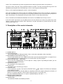
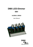
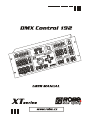
3. Description of the control elements
1 - POWER SWITCH
2 - FUNCTION-DISPLAY
The Function-display has different functions. Please refer to the explanations under "Operation".
3 - DMX CHANNEL/FUNCTION-BUTTONS 1-12
Every Function-button represents a DMX-channel of the respective projector to which it is assigned. Please
take the DMX channel-occupation from the user manual of the respective projector.
4 - LEVEL/FIXTURE TYPE + - -BUTTONS
By pressing the Up/Down-buttons you can adjust the settings stepwise. By holding the button, you can
quickly browse through the display.
5 - FIXTURE-BUTTONS
For selecting the desired projector(s).
6 - ALL-BUTTON
The button selects all similar type "Fixture".
7 - CLEAR-BUTTON
Clears all manual selections made with the FIXTURE TYPE (
) – buttons.The LED of each individual
fixture will be turned off.
CLEAR/CLEAR-function.This function allows the controller to return to its original setting when turned on, all
displays are cleared, regardless of the function settings that you are currently using.
Press the CLEAR-BUTTON 2 times in sequence rapidly.All displays will show "---------".
8 - MEMORY CARD CONNECTOR
Plug the Memory Card in here.
9 - SAVE-BUTTON
The SAVE-BUTTON has the following functions:
5
"Save Data" for saving the settings and programs on the memory card. Please refer to the explanations
under "Operating the memory card".
"Set Desk Lamp" for adjusting the desk lamp intensity. Please refer to the explanations under "Desk lamp".
10 - LOAD/SET UP-BUTTON
The LOAD BUTTON - has the following functions:
"Load Data" for loading data from the Memory Card into the memory of the controller.
"Change Device" for displaying the desired projectors and allows the inclusion of the 3 devices not contained
in the library .
"Load Factory Setup" for setting the controller back to the factory setup. Caution: all data in the controllermemory will be lost.
11 - DESK LAMP CONNECTOR
An XLR-connector for mounting of a suitable desk lamp (12V).
12 - JOYSTICK
For manual control of the pan/tilt movement. The joystick has to be activated by pressing the ON/OFFBUTTON,PAN-BUTTON and TILT-BUTTON. Otherwise, it has no function.
13 - DIRECTION-BUTTONS
For manual control of the pan/tilt movement. The buttons are for fine-adjusting the pan/tilt and are immediately
ready for use. For the fine-mode in the 16-bit-mode, the 8/16 Bit-key has to be pressed (LED shines).
14 - ON/OFF-BUTTON
For activating the joystick.
15 - PAN-BUTTON
For activating the pan-movement of the joystick.
16 - TILT-BUTTON
For activating the tilt-movement of the joystick.
17 - FAST/SLOW-BUTTON
For adjusting the two speeds of movement.
18 - 8/16 BIT-BUTTON
For switching the pan/tilt-movement from 8 to 16 Bit resolution.
19 - PROGRAM-DISPLAY
20 - PROGRAM-BUTTON
This button in programming mode allows for the recording of projector movements which can be played back
as required.
21 - SCENE-BUTTON
This button in programming mode allows for the recording of static projector scenes which can be played
back as required.
22 - STEP-BUTTON
The button in programming mode allows for the recording of a program step which can be played back as
required.
23 - NEXT-BUTTON
The button allows the selection of the next step in run mode.
24 - INSERT/PROG.RELEASE-BUTTON
Programing mode-iserting of a new step into existing program.Operating mode-stopping the output
of the current program.
25 - COPY/SCENE RELEASE-BUTTON
Programming mode-copying of a current scene.Operating mode-stopping the output of the current program.
26 - DELETE/MAN.RELEASE.-BUTTON
Programming mode-deleting of a current scene.Operating mode- releasing the current selected projectors.
27 - ENTER-BUTTON
The button confirms the selection
28 - EFFECT+/- - BUTTONS
The buttons allow setting the values on the PROGRAM DISPLAY.
29 - +1 STEP-BUTTON
With this button , you can jump from one step to another. Caution: The +1STEP-BUTTON only works in the
run-mode.
30 - AUTO-BUTTON
If the LED shines, the controller is in Auto-mode (normal operating mode without sound-control).
31 - AUDIO-BUTTON
If this LED shines the controller is in Audio-mode (operation with sound-control, the signal has to be connected
on the rearpanel).
32 - BLACKOUT-BUTTON
The Blackout-function closes the light output of all connected projectors via the shutter. Please note that all
other functions of the projectors are maintained and that the programs keep running.
6
Caution: The BLACKOUT-BUTTON has to be pressed (LED is off), as soon as a program is called up.
Otherwise there will not be any light output.
33 - FADE TIME-BUTTON
The button activates the FADE TIME-SLIDER
34 - STEP TIME-BUTTON
The button activates the STEP TIME-SLIDER
35 - FADE TIME-SLIDER
The slider adjusts the fade time between the programs steps
36 - STEP TIME-SLIDER
The slider adjusts the hold time of the program steps
7
4. Installation
4.1.Sound-control
If the DMX CONTROL 192 is supposed to work via a soundsignal, connect the ¼" jack plug with the soundsignal
of your headphones output or a second adjustable output (if existing) of your mixer, or with the loud-speaker
output of your amplifier.
Tip:
Data +
Sleeve:
Ground
Caution: Never connect the sound input with the DMX-output, as this will destroy the electric (DMX-driver).
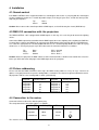
4.2.DMX-512 connection with the projectors
The DMX CONTROL 192 is equipped with 2 DMX-outputs. In this way, it is easier for you to connect the lighting
effects.
Connect the DMX-output of the controller with the DMX-input of the nearest lighting effect. Splitting the DMX-line
is not possible. Continue the DMX-line by connecting the DMX-output of the projector with the next DMX-input.
Use a data line appropriate for RS-485, 250Kbaud data use or a shielded quality double-wire cable. As a plug
contact use ¼" stereo jack-plugs or 3-pin XLR-connector, the terminals of which are as follows:
Tip:
Ring:
Sleeve:
Data +
Data Ground
PIN 1 - Ground
PIN 2 - Data PIN 3 - Data +
Caution: At the last projector, the DMX-cable has to be terminated with a 120 Ω resistor. Solder the resistance
into a 3 pin XLR-connector and plug it in the DMX-output of the last projector.
4.3 Fixture addressing
Please note that the DMX CONTROL 192 assigns the DMX-starting addresses every 16 steps. You have to
address every projector to the respective starting address. Otherwise, the channel assignment will not be correct.
All projectors with the same starting address work synchronically.
Projector
Projector 1
Projector 2
Projector 3
Projector 4
Projector 5
Projector 6
Starting address
1
17
33
49
65
81
Projector
Projector 7
Projector 8
Projector 9
Projector 10
Projector 11
Projector 12
Starting adress
97
113
129
145
161
177
4.4 Connection to the mains
Connect the fixture to the mains with the power-plug.
The occupation of the connection-cables is as follows:
Cable (EU)
Cable (US)
Pin
Brown
Black
Live
L
Light blue
White
Neutral
N
Yellow/Green
Green
Earth
The earth has to be connected!
8
International
4.5.Accessory included in the delivery
The delivery includes 1 controller and 1 memory card. The memory mard can be used for copying the internal
memory (RAM) of the DMX CONTROLER 192 to the memory card and to safe the adjustements and programs
externally (data backup). The controller can immediately be used, also if the memory card is not plugged in. Only
mount the memory card when needed.
Caution: When you turn the device on, the controller is in blackout-mode (Blackout-LED on).
4.6.Desk lamp
If you wish, you can plug an appropriate desk lamp (12V DC) into the XLR3 socket on the top panel. The desk
lamp intensity can be adjusted from 0-100%.The factory setup is 50%.
Description of the XLR3 socket: Pin 1=not connected
Pin 2=+12V DC adjustable
Pin 3=0V DC
Press the SAVE-button 2 times untill the Function and Program display shows "SET DESK LAMP".Press the
ENTER-button and use the FADE TIME-slider to adjust the intensity of the lamp.Press the ENTER-button to
confirm your selection.
5.Assigning the desired projectors
The factory setup determines all FIXTURE-buttons to the SPOT 250 XT. You can assign a FIXTURE-buttons to
any other projector.
Selection a XT- projectors
1.Press the LOAD/SET UP-button below the memory card until the the displays show "SET DMX LINE".
2.Press the ETER-button. The Fixture-button LED No. 1 will shine and the Function Display shows the current
projector.
3.Select the desired XT-projector by pressing the LEVEL/FIXTURE TYPE (
) buttons.
Overview over the available projectors:
NAME
Spot 150 XT
Wash 150 XT
Spot 160 XT
Spot 250 XT
Wash 250 XT
MSZoom 250 XT
Spot 575 XT
Wash 575 XT
DJ Scan 150 XT
DISPLAY
SPOT 150
WASH 150
SPOT 160
SPOT 250
WASH 250
MSZom.250
SPOT 575
WASH 575
DJ SC.150
NAME
DJ Scan 250 XT
Scan 250 XT
Scan 575 XT
Scan 1200 XT
Ecolor 250 XT
Beam 250 XT
User defined
User defined
User defined
DISPLAY
DJ SC.250
SCAN 250
SCAN 575
SCAN1200
ECOL. 250
BEAM 250
SPOT 1
SPOT 2
SPOT 3
4.Confirm the selection by pressing the ENTER-button.
The Fixture-button LED No. 2 will shine and the Function Display shows the current projector.
5.Repeat steps 3-4 to assign projectors 3 to 12 which you wish to control.
6.Press the LOAD/SET Up-button to terminate this procedure.Function and Program Display shows:" – – – – –".
It is advisable to keep similar fixtures on adjacent FIXTURE buttons.
NOTE: You may create new projector “personalities” which are not in the DMX CONTROL 192 library. To
do this use the three fixture names SPOT 1, SPOT 2 and SPOT 3, assign a DMX address and then define the
fixtures as described in article Setting up the projectors not defined in the DMX CONTROL 192 library.
5.1.Setting up the projectors defined in the DMX CONTROL 192 library
1.Press the LOAD/SET UP-button until the the display shows "CHANGE DEVICE".
2.Press the ENTER-button. Press the LEVEL/FIXTURE TYPE (
) – buttons until the required projector is
displayed on the Function Display.
3.Press the ENTER-button.The Function Display shows the function of the first channel. The Program Display
shows the current channel-number ("CHAN.01"). Check the channel-occupation by pressing the EFFECT (
) buttons. The displays show the channel number and the respective function(abbreviated).The LEDs of the
Function buttons or joystick buttons shines if the function is assigned.
9
NOTE: you will notice that the LEDs of the functions buttons (BLACKOUT,FADE TIME) will come on in association
with the dimmer and blackout channels; this indicates that during the operation of the controller when the BLACKOUTbutton is pressed both these two channels will be operated to ensure a blackout.
NOTE: you will notice that the LED of the FADE TIME- button will come on in association with the pan,tilt , pan/
tilt fine and dimmer channels; this indicates that during the operation of the controller when these channels are
used they will be subject to the setting determined by the FADE TIME- slider.
Example for the occupation of the function buttons (SPOT 250 XT):
Function/button
Pan
Tilt
Pan + 8/16 Bit
Tilt + 8/16 Bit
Function/button Function
F1
Speed
F2
Power
F3
Colour
F4
No function
F5
Effect-wheel
F6
Prism-rotation
Function
Pan-movement
Tilt-movement
Pan 16 Bit
Tilt 16 Bit
DMX-channel
1
2
3
4
DMX-channel
5
6
7
8
9
10
Function/button
F7
F8
F9
F10
F11+Blackout
F12+Blackout
+Fade Time
Function
Rotating Gobo
Gobo Rotation
No function
Focus
Shutter
Dimmer
DMX-channel
11
12
13
14
15
16
By pressing the CLEAR-button 2 times rapidly you can return the controler to its original state
If the channel-occupation is correct and the FUNCTION buttons are correct, press the ENTER-button.
)buttons and check(determine) the next projector.
Press the LEVEL/FIXTURE TYPE (
5.2.Setting up the projectors not defined in the DMX CONTROL 192
library
1.Press the LOAD/SET UP-button until the the display shows "CHANGE DEVICE".
2.Press the ENTER-button. Press the LEVEL/FIXTURE TYPE (
) – buttons until the "SPOT1 GENERIC" is
displayed on the Function and Program displays.
3.Press the ENTER-button.The Function Display shows the function of the first channel (abbreviations). The
Program Display shows the current channel-number ("CHAN.01").
4.You must now assign to each of the 16 channels the effect which each will control and the respective buttons
and sliders which will operate them on the controller:
The EFFECT (
) buttons select the channel number to which respective effects are assigned.
The LEVEL/FIXTURE TYPE (
) buttons select the name of the function.
The DMX CHANNEL/FUNCTION buttons assign the 12 DMX CHANNEL buttons to 12 projector functions.
The PAN- button allows the pan movement of the projector to be assigned to the joystick.
The 8/16 BIT- button allows a 16 bit pan/tilt movement to be assigned to the joystick.
The TILT- button allows the tilt movement of the projector to be assigned to the joystick..
The list of an abbreviations used for describing projector functions:
PAN= pan
R.G2.
TILT= tilt
R.G3.
F.PA.= fine pan
R.PR.
F. TIL.= fine tilt
R.CO.
COL.= colour
ROT.= rotation
CO.1.= colour 1
RO.1.
CO.2.= colour 2
RO.2.
CO.3.= colour 3
RO.3.
C.– G.= colour/gobo
G.RO.= gobo rotation
GOB.= gobo
P. R O.= prism rotation
S.GO.=static gobo selection E.RO.= effect rotation
S.G1.
C.RO.= colour rotation
S.G2.
EFF.= effects
S.G3.
EF1.= effects 1
R.GO.=rotating gobo selection EF2.= effects 2
R.G1.
EF3.= effects 3
10
SHU.= blackout
STR.= strobe
IRI.= iris
ZOM.= zoom
FOC.= focus
DIM.= dimmer
SPD.= speed
TIM.
PWR.= powering up
FAN.= fan
X1.
X2
X3.
X4.
X5.
X6.
Y1.
Y2.
Y3.
Y4.
Y5.
Y6.
F1.
F2.
F3.
F4.
F5.
F6.
F7.
F8.
F9.
F10.
F11.
F12.
FNC.= special function
CYA.= cyan
MAG.= magenta
YEL.= yellow
FRO.= frost
M.T.S.= motor speed
BEA.= beam
FILT.= filter
B.OU.= Blackout
GAM.= program selection
TRIG.= trigger
RES.= reset
MAC.=macros
C.SP.= colour speed
G.SP.= gobo speed
E.SP= effects speed
P.SP.
X.SP.= X-axis speed
Y.SP.= Y-axis speed
Z.SP
FLA.
FREE= no function
Press the ENTER-button to record the assigments you have made.
Note:You also have to determine which channel will have the blackout-function and which channel should react to
the fade-time. It is important to adjust the fade-time function for the pan and tilt in order to control the speed of the
movement during the program-run.
6. Manual control of the projectors
Manual mode allows you to directly control the functions of any projector connected to the controller.
In order to control each projector it is necessary to know what function each individual channel controls on the
respective projectors.This data is in the instruction manual of each individual projector.
6.1.Reading out the functions and DMX-alues
The Function Display consists of 3 fields: Function, 8 Channel value and 16 Bit Value.
If the display shows "------" in the fields, the display is empty and no mode is active.
As soon as the fixture is selected and one FUNCTION-button is pressed, the Function Display shows the
selected function under Function, the current DMX-value under Channel value and "--" under 16 Bit value.
6.2.Adjusting the DMXvalues
Press the FUNCTION-button of the desired control channel. The display shows the current DMX-value. Adjust the
desired value via the LEVEL/FIXTURE TYPE (
) – buttons. When you press the +-button, the DMX-value will
be increased, if you press the --button, it will be decreased. By pressing the respective button, you can quickly
adjust the values.
Note:
Press the + and – buttons simultaneously: the displayed values will move to 128.
Hold down the + button and press the - button: the displayed values will move to 255 (maximum ).
Hold down the - button and press the + button: the displayed values will move to 0 (minimum).
Please take the channel-occupation from the user manual of the respective projector.
6.3.Reading out the pan/tilt values
The current pan/tilt position can be read out on the Function Display as follows:
As soon as the PAN-button or one of the DIRECTION-buttons RIGHT or LEFT is pressed, the Function Display
shows "PAN" under Function, the current 8 Bit DMX value under Channel value and the current 16 Bit DMX value
under 16 Bit value.
As soon as the TILT-button or one of the DIRECTION-buttons UP or DOWN is pressed, the display shows "TILT"
under Function, the current 8 Bit DMX value under Channel value and the current 16 Bit DMX value under 16 Bit
value.
As soon as the PAN-button and the TILT-button are pressed at once or the DIRECTION-buttons RIGHT or LEFT
and UP and DOWN are pressed, the display shows for example "P.131 T.128", only the current 8 Bit DMX value
is displayed.
6.4.Adjusting the pan/tilt-position via the joystick
Activate the joystick by pressing the ON/OFF-button (LED shines). Press the PAN-button or the TILT-button in
order to control both directions.
Adjust the desired position via the joystick. The display shows the current 8 Bit DMX value.
6.5.Adjusting the pan/tilt-position via the DIRECTION-buttons
By pressing the desired DIRECTION-button, you can adjust the pan/tilt position step by step. By holding the
respective button, you can make a smooth movement.
11
6.6.Adjusting the resolution of the pan/tilt-movement
You can adjust the resolution of the pan/tilt movement via the 8/16 BIT-button from 8 Bit to 16 Bit. If the button is
pressed, the controller is in 16 Bit-mode (high resolution). In this mode, the pan/tilt can exactly be positioned.
6.7.Adjusting the speed of the pan/tilt-movement
You can adjust the speed of the pan/tilt movement via the FAST/SLOW-button. If its LED is off, the pan/tilt
movement is fast, if the LED shines, the pan/tilt movement is slow. This function is only available for the DIRECTIONbuttons.
Option 1:
The FAST/SLOW-button is not pressed, its LED is off (Fast-mode). The 8/16 BIT-button is not pressed, its LED is
off (8 Bit-mode).
The pan/tilt position changes in 10-fold steps (e.g. 131, 141, 151 etc.).
Option 2:
The FAST/SLOW-button is pressed, its LED shines (Slow-mode). The 8/16 BIT-button is not pressed, its LED is
off (8 Bit-mode).
The pan/tilt position changes in 1-fold steps (e.g. 131, 132, 133 etc.).
Option 3:
The FAST/SLOW-button is not pressed, its LED is off (Fast-mode). The 8/16 BIT-button is pressed, its LED
shines (16 Bit-mode).
The pan/tilt position changes in 0.5-fold steps (e.g. 131; 131,5; 132 etc.).
Option 4:
The FAST/SLOW-button is pressed, its LED shines (Slow-mode). The 8/16 BIT-button is pressed, its LED shines
(16 Bit-mode).
The pan/tilt position changes in 0.01-fold steps (e.g. 131; 131,01; 131,02 etc.).
7.Programming
DMX CONTROL 192 is a programmable controller. It may be used in either manual mode or programmed mode to
achieve the required outputs.
To program the controller, you must first develop your static scenes and then build these into a program.
7.1.Programming and modifying a lighting scene
Scenes are the building blocks used to build up programs.
Recording a scene means recording the positions and using effects which you have set your projectors to do.
Once you have recorded a scene, you may use it either individually or use it to build along with other scenes into
a program.
DMX CONTROL 192 allows you to record up to 500 static scenes.
Note: remember that once you have set the level to turn on the lamp, you should ensure that it remains at this
level to avoid problems such as the lamp going off or the projector resetting.
1.Press the CLEAR-button until the Function Display shows"--------"
2.Simultaneously press the LOAD/SET UP and SAVE buttons, the LEDs of the two buttons will flash, indicating
the controller is in programming mode.
3.Press the SCENE-button.The displays show "SELECT SCN.---"
4.Press the + button and the displays will show"SELECT SCN.001".If the sign"001" flashs alternatively with
"EMP" ,the scene is empty.Select the scene number 1-500 by pressing +/-buttons.
5.Press the ENTER-button,the sign "SELECT" will disappear and the scene is selected.
6.Press the FIXTURE-button 1-12 to select the projectors you wish to use in your scene.
7.Press the DMX CHANNEL/FUNCTION-button 1-12 to select the desired function and by the LEVEL/FIXTURE
TYPE (
)-buttons change the adjusted values(if you wish).
8.Press the COPY-button to move on to the next scene.The displays will show"SELECT SCN.002".If the sign"002"
flashs alternatively with "EMP" ,the scene is empty.By pressing +/-buttons you can select another scene.
9.Press the ENTER-button an the scene will be recorded.
10.Repeat steps 6-9 to record up to 500 scenes.
11.Simultaneously press the LOAD/SET UP and SAVE buttons, the LEDs of these buttons will turn off, indicating the controller is no longer in programming mode.
12
7.2.Recording programs and steps
You can create up to 40 programs with a maximum of 99 steps each. Each step is selected from the previously
recorded scenes .
Creating a program is simply a matter of assigning each step a previously recorded scene number.
Each program step has a dynamic part(fade time) and static part(step time):
Fade time-the time,during which effects move to the programmed position.
Step time-the time,during which effects last in the current step.
1.Press the CLEAR-button until the Function Display shows"--------".
2.Simultaneously press the LOAD/SET UP and SAVE buttons, the LEDs of the two buttons will flash, indicating
the controller is in programming mode.
3.Press the PROGRAM-button.The displays show "SELECT PROG.01"
4.Pres the +- buttons in the Program section until you have selected the number of the program which you wish
to create.
5.Press the ENTER-button,the displays will show"SELECT STEP.01".If the sign"01" flashs alternatively with "-E" ,the step is empty-no scene is associated with it.
6.Press the ENTER-button,the displays will show"SELECT SCN.---".
7.Select the scene number (1-500) which you wish to associate with this step by pressing +/--buttons.
8.Press the ENTER-button,to confirm your selection.The displays show "SELECT TIME".
9.Press the FADE TIME-button (the LED shines) and use the FADE TIME-slider to select the fade time (0,1-9,9s)
10.Press the STEP TIME-button (the LED shines) and use the STEP TIME-slider to select the step time (0,19,9s).
11.Press the ENTER-button to confirm your selection of the step.
12.Repeat the instructions 5-11 to record other program steps.In many cases, you may not wish to use all 99
steps in a loop,by simultaneously pressing the + and - buttons you may terminate a program.The Program
Display will show "E "(the end of the program).
The number of steps in your program will be determined, therefore, by the position in which you place
the E for the end of the program.
13.Repeat the instructions 2-12 for every program which you create.Simultaneously press the LOAD/SET UP and
SAVE buttons, the LEDs of the two buttons will turn off, indicating the controller is not in programming mode.
8.Recall and run mode
The following instructions needed to recall and run previously recorded scanes and programs.
8.1.Recalling scenes
1.Press the CLEAR-button until the Function Display shows"--------".
2.Press the SCENE- button in the Effects zone.The displays will show "SELECT R.SC.—-".
3.Pres the +/- buttons in the Effect section until you have selected the number of the scene which you wish to
view (e.g. R.SC.003).
4.Press the FIXTURE-buttons 1-12 to select the projectors (you can use the ALL-button or CLR-button) you wish
to use in the selected scene.
5.Press the FADE TIME-button (the LED shines) and use the FADE TIME-slider to select the fade time (0,1-9,9s).
6.Press the ENTER-button promptly twice to confirm your selection of the scene.The sign"R.SC.003" will appear
on the Program Display (R is flashing).
Note that the BLACKOUT LED is On on the BLACKOUT- button and that pressing the button will cause all active
projectors to go into blackout mode.
7.Press the SCENE RELEASE-button (its LED is flashing whilst the scene is active) to end the selected scene.
NEXT-button
Using this button allows you to change from the active scene.Repeat steps 1 to 7 to activate a scene using your
current projectors.
8.Press the NEXT-button in the Effects section.The button LED flashes and the displays show"SEL. PROG. OR
SCN.".
Press the SCENE-button if you want to view another scene.
9.Pres the +- buttons in the Effect section until you have selected the number of the scene which you wish to use
to replace the active ecene (e.g. R.SC.006).
10.Press the FIXTURE-buttons 1-12 to select the projectors (you can use the ALL-button or CLR-button) you wish
to use in the selected scene.
11.Press the ENTER-button,the sign"SELECT" will disappear.
13
13.Press the FADE TIME- button to change the speed at which the projectors move or to activate the dimmer.
Use the FADE TIME- slider to adjust the desired values on the Program Display.
14.Press the ENTER-button to confirm selection.The Program Display will show sign "R.SC.006" (R.is flashing).
Repeat the steps 8-14 as many times as required in order to view the desired pre-recorded scenes.
8.2.Recalling programs
1.Press the CLEAR-button until the Function Display shows"--------".
2.Press the PROG.- button in the Effects zone.The displays will show "SELECT R.PRG.—-".
3.Pres the +- buttons in the Effect section until you have selected the number of the program which you wish to
view (e.g. R.PRG.008).
4.Press the FIXTURE-buttons 1-12 to select the projectors (you can use the ALL-button or CLR-button) you wish
to use in the selected scene.The LEDs at selected buttons will start flashing.
5.Press the ENTER-button,the sign"SELECT" will disappear and the LED of the STEP-button is On.Program
Display shows "STEP.01", if the sign"01" flashs alternatively with "--E" ,the step is empty-no scene is associated
with it.
6.Pres the +- buttons in the Effect section until you have selected the starting step for your program (e.g.STEP.03).
7.Press the FADE TIME- button and use the FADE TIME-slider to change the time the program takes to fade in
and out of a scene or simply leave it at the speed which was set when the program was created.
8.Press the STEP TIME- button and use the STEP TIME-slider to change the hold time for each step or simply
leave it at the speed which was adjusted when the program was created.
Note:The values on the STEP TIME-slider and FADE TIME-slider multiply the original step values.
For example: program step: original fade time = 1,2s ,original step time =8
FADE TIME-slider value=2 , STEP TIME-slider value=0,5
total program step times: fade time=2,4s , step time= 4s
9.Select the type of the advancement for your program in the Trigger section.You can choose from:
+1 STEP-button = manually at each press of the button; Fade Time is active.
AUTO-button = automatically, using the program timing.
AUDIO-button = in sound-to-light mode, following the beat of the music source inserted at the rear of the controller, fade time is active.
10.Press the ENTER-button to confirm your selection of the mode,the sign"R.PRG.008" will appear on the
Program Display (R is flashing).
Note that the BLACKOUT LED is On on the BLACKOUT- button and that pressing the button will cause all active
projectors to go into blackout mode.
You can change the fade and step time if you wish
11.Press the FADE TIME-button (the LED shines) and use the FADE TIME-slider to set the fade time (0,1-9,9s)
12.Press the STEP TIME-button (the LED shines) and use the STEP TIME-slider to select the step time (0,19,9s).
13.You can change the type of the trigger by using the 3 modes described above (+1STEP,AUTO,AUDIO buttons)
14.Press the PROG. RELEASE-button (its LED is flashing whilst the scene is active) to end the current running
program.
NEXT-button
Using this button allows you to change the active program or temporarily put an additional scene to the current
state.Repeat steps 1 to 13 to activate a program using your current projectors.
14.Press the NEXT-button in the Effects section.The button LED flashes and the displays show"SEL. PROG. OR
SCN.".
15.Press the SCENE-button if you want to use a scene or the PROGRAM-button if you wish to change the current
program.The scenes can be transfered to other projectors not included in the current program and the effects
superimposed onto the current program.
16.Pres the + button or -button in the Effect section until you have selected the number of the scene or program
which you wish to use in place or to superimpose over the active (e.g. R.PRG.010).
17.Press the FIXTURE-buttons 1-12 to select the projectors (you can use the ALL-button or CLR-button) you wish
to use in the next scene or program (LEDs On).
18.Press the ENTER-button,the sign"SELECT" will disappear.
19.Press the FADE TIME- button to change the speed at which the projectors move or to activate the dimmer.
Use the FADE TIME- slider to adjust the desired values on the Program Display.
20.Press the ENTER-button to confirm selection.The Program Display will show sign "R.PRG.010" (R.is flashing).
Repeat the steps 13-20 as many times as required.
Note that since you currently have both a scene and a program active, the LEDs for the respective PROGRAM
RELEASE- button and SCENE RELEASE- button flash and you can end each of the two independently of the
other.
14
9.Manual control of the projectors if the scene or program is active
Any projector can be operated manually whilst either a scene or a program is currently active.
When a scene or program is running, press the relative FIXTURE-button 1-12 of the projectors you wish to control
manually, and proceed as described in section Manual control of the projectors.
Manually selected projector will repond to your direct movement commands from the controller, and will also
respond to its other parameters to the currently active scene or program.
When you take manual control of a projector the LED relative to the MANUAL RELEASE- button will begin to
flash.
To return the projectors to the control of the active scene or program press the MANUAL RELEASE-button.
10.Modifying a created program
You can modify previously recorded programs or scenes using the INSERT-button and DELETE-button.
INSERT-button
By this function you can insert a step into a previously recorded program.
1.Press the CLEAR-button until the Function Display shows"--------".
2.Simultaneously press the LOAD/SET UP and SAVE buttons, the LEDs of these two buttons will flash, indicating
the controller is in programming mode.
3.Press the PROGRAM-button.The displays show "SELECT PROG.01"
4.Press the +/-buttons in the Effects section until you reach the program you wish to change (e.g. SELECT
PROG.04")
5.Press the ENTER-button ,the displays show "SELECT STEP.01"
6.Pres the +/- buttons in the Program section until reach the step prior to the one where you wish to
insert your new step (eg. SELECT STEP.05 - the previous step 5 becomes step 6).
7.Press the INSERT-button (its LED is on).
8.Press the ENTER-button.
9.Press the SCENE-button to select scene you wish to associate with the step (its LED is on)
10.Pres the +- buttons in the Effects section until you reach the scene which you wish to
insert (eg. SELECT SCN.005 ).
11.Press the ENTER-button,to confirm selection.The displays show"SELECT TIME".
12.Press the FADE TIME- button and use the FADE TIME-slider to adjust the fade time that you wish to use
between the new step and the following step.
13.Press the STEP TIME-button and use the STEP TIME-slider to adjust step time for the new step.
14.Press the ENTER-button to insert the new step in the program.
15.Simultaneously press the LOAD/SET UP and SAVE buttons to exit the programming mode.
DELETE-button
By this function you can delete a step from the program.
1.Press the CLEAR-button until the Function Display shows"--------".
2.Simultaneously press the LOAD/SET UP and SAVE buttons, the LEDs of these two buttons will flash, indicating
the controller is in programming mode.
3.Press the PROGRAM-button.The displays show "SELECT PROG.01"
4.Press the +-buttons in the Effects section until you reach the program you wish to change (e.g. SELECT
PROG.04).
5.Press the ENTER-button ,the displays show "SELECT STEP.01"
6.Pres the +- buttons in the Program section until you reach the step you wish to remove from the program
eg. SELECT STEP.05 (the previous step 5 becomes step 4).
7.Press the DEL-button (its LED is on).
8.Press the ENTER-button.This program step is permanetly deleted.
9.Simultaneously press the LOAD/SET UP and SAVE buttons to exit the programming mode.
Once created program, you can overwrite step by step or cut down.
For example,you want to cut down the program 11 at step 10:
1.Press the CLEAR-button until the Function Display shows“————“.
2.Simultaneously press the LOAD/SET UP and SAVE buttons, the LEDs of these two buttons will flash, indicating
the controller is in programming mode.
15
3.Press the PROGRAM-button.The displays show „SELECT PROG.01“
4.Press the +- buttons in the Effect zone until you reach the program you wish to change (e.g. SELECT PROG.11).
5.Press the ENTER-button ,the displays show „SELECT STEP.01“
6.Pres the +- buttons in the Effect zone until you reach the step you wish to stop the program
eg. SELECT STEP.10 .
7.Press the DEL-button (its LED is on).
8. Simultaneously press + - buttons for short time.( DEL-button LED is off)The program is finished at this step.The
character “E” is blinking.
Note:The following steps 11,12,13....are existed(if were created) but the step 10 is “stopper”- character “E”.
If you press ENTER-button and assign the certain scene to the step 10,you can continue on step 11,12...
In fact, you don´t delete the next steps,only assign the “stopper”.
9.Simultaneously press the LOAD/SET UP and SAVE buttons to exit the programming mode.
11.Operating the memory card
Unpack the Memory Card and plug it into the connector on the top panel.
Important shows should always be saved on the memory card. Only in this way you can avoid that data is lost
due to misuse or accidental deletion. The capacity of the memory card (1 Mb) is enough to save all 500 scenes
and the program data.
11.1.Saving data to the memory card
Caution: If you save data on the memory card, all data that has been saved on the memory card before will be
lost.
Press the SAVE-button until the display shows "Save Data". Press the ENTER-button and hold it for approx. 5
seconds. The controller saves the data on the memory card,the SAVE-led will flash and the displays will go off .
The operation takes approx. 10-15 seconds.
11.2.Loading data from the memory card into the controller- memory
Caution: If you load data into the controller-memory, all data (except factory setup) that has been in the memory
before will be lost.
1.Press the LOAD/SET UP-button until the display shows "LOAD DATA".
2.Press the ENTER-button and hold it for approx. 5 seconds. The controller loads the data into the controllermemory. The displays will go off.
The operation takes approx. 10-15 seconds.
12.Returning to the factory setup
Caution:The operation described below will permanently erase all settings which have been set by the operator,
you should save the controller memory contents to the memory card before you make a reset.
If you have important show data in controller memory,it is absolutely necessary to save data on the memory card
(backup)!
1.Press the LOAD/SET UP-button until the displays show "LOAD FAC. SETUP".
2. Press the ENTER-button and All-button together hold it for approx. 5 seconds until the contents of the memory
are reseted.
13. Technical specifications
Power supply:
Fuse:
Fuse:
Power consumption:
Number of control channels:
Sound input:
Audio-sensitivity:
DMX 512-output:
Recordable programs:
Recordable scenes:
Controller RAM:
Memory card:
Dimensions (LxWxH):
Weight:
115V, 200-230V AC, 50/60Hz ~
0,063A@230V
0,120A@120V
15 VA
192
¼” mono Jack
0.5 - 2 V
via two 3-pin XLR-connectors
40 with up to 99 steps each
500
1Mb
1Mb
483 x 176 x 70 mm
2 kg
16
14.Cleaning and maintenance
DANGER!
Disconnect from the mains before starting any
maintenance work
There are no servicable parts inside the device. Maintenance and service operations are only to be carried out by
authorized dealers.
Never use solvents or aggressive detergents in order to clean the device! Rather use a soft damp cloth.
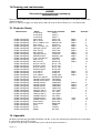
15. Projector library
Manufacturer
ROBE show lighting
ROBE show lighting
ROBE show lighting
ROBE show lighting
ROBE show lighting
ROBE show lighting
ROBE show lighting
ROBE show lighting
ROBE show lighting
ROBE show lighting
ROBE show lighting
ROBE show lighting
ROBE show lighting
ROBE show lighting
ROBE show lighting
ROBE show lighting
ROBE show lighting
ROBE show lighting
ROBE show lighting
ROBE show lighting
ROBE show lighting
ROBE show lighting
ROBE show lighting
ROBE show lighting
ROBE show lighting
ROBE show lighting
ROBE show lighting
ROBE show lighting
ROBE show lighting
ROBE show lighting
ROBE show lighting
ROBE show lighting
ROBE show lighting
ROBE show lighting
ROBE show lighting
ROBE show lighting
ROBE show lighting
ROBE show lighting
Name
Name in the controller
User defined
SPOT 1
User defined
SPOT 2
User defined
SPOT 3
Spot 150 XT
SPOT 150
Wash 150 XT
WASH 150
Recessed Wash 150
RWASH 150
Spot 160 XT
SPOT160
Recessed Spot 170
RSPOT 170
ColorSpot 170 AT
CSP170AT
Spot 250 XT
SPOT 250
Wash 250 XT
WASH 250
ColorSpot 250 AT
CSP250AT
MSZoom 250 XT
MSZoom. 250
Image Spot 250 AT
ISP250AT
Spot 575 XT
SPOT 575
Wash 575 XT
WASH 575
DJ Scan 150 XT
DJ SC. 150
DJ Roller 150 XT
DJ RO.150
DJ Scan 250 XT
DJ SC. 250
DJ Roller 250 XT
DJ RO.250
Scan 250 XT
SCAN 250
Scan 575 XT
SCAN 575
Scan 1200 XT
SCAN 1200
Dominator 1200 XT
DOMINATOR
ColorMix150 AT Profile CM150ATP
ColorMix150 AT Wash
CM150ATW
ColorMix 240 AT
CMX240AT
ColorMix 250 AT
CMX250AT
ColorMix 550 AT
CMX550AT
ColorMix 575 AT
CMX575AT
ClubScan 150 CT
CSC.150CT
ClubRoller 250 CT
CR. 150CT
ClubScan 250 CT
CSC.250CT
ClubRoller 250 CT
CR. 250CT
ClubSpot 250 CT
CSP. 250CT
ClubWash 250 CT
CWA. 250CT
Ecolor 250 XT
ECOL.250
Beam 250 XT
BEAM 250
Funky
FUNKY
Fusion
FUSION
HipHop
HIP HOP
Mode
Mode 1
Mode 1
Mode 1
Mode 1
Mode 1
Mode 1
Mode 1
Mode 1
Mode 4
Mode 1
16 bit
Mode 1
Mode 1
Mode 1
Mode 1
Mode 1
Mode 2
Mode 2
Mode 2
Mode 2
16 bit
16 bit
-
Channels
8
8
8
9
12
12
16
16
16
16
10
16
16
4
4
6
6
16
16
16
12
4
3
8
10
8
11
6
6
6
6
10
10
6
4
3
3
4
16. Appendix
We believe you will enjoy your DMX CONTROL 192. We assure you will enjoy this product for years if you follow
the instructions given in this manual.
If you have any questions and comments, please do not hesitate to contact us.
Version 1.2
17