1
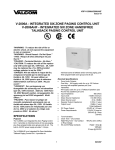
VSP-V-2901A
Issue 4
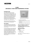
V-2901A
UNIVERSAL DOOR ANSWERING SYSTEM
INTRODUCTION
The V-2901A, Universal Door Answering System,
when used with Valcom Doorplate Speakers,
provides voice paging with handsfree reply to a door
from any telephone location. The V-2901A initiates
ring-in on the telephone system and sends a
confirmation tone to the door speaker. The individual
at the phone responding to the signal will determine if
access should be allowed. Pressing a programmed
code on the telephone dialpad or pressing the remote
button will unlock the door to allow admission. The
V-2901A also provides an alarm control output to
alert an alarm system of an unauthorized entry.
These instructions contain the specifications and
information necessary to install, operate and maintain
the Universal Door Answering System.
FCC Notice
This equipment generates and uses radio frequency
energy and if not installed and used properly, that is,
in strict accordance with the instructions listed in this
User's Manual, may cause interference to radio and
television reception.
It has been tested and found to comply with the limits
for a Class B Computing Device in accordance with
the specifications in Subpart B of Part 15 of the FCC
rules, which are designed to provide reasonable
protection against such interference in a residential
installation. If this equipment does cause interference
to radio or television reception, which can be
determined by turning off the equipment and seeing if
the interference stops, the user is encouraged to try
and correct the interference by one or more of the
following measures:
1
Reorient the receiving antenna.
Relocate the equipment with respect to the radio
or television.
Move the equipment further away from the radio
or television.
Plug the equipment into a different branch
circuit.
NOTE: The manufacturer is not responsible for
any radio or TV interference caused by
unauthorized modifications to this equipment.
Such modifications could void the user's authority
to operate the equipment.
SPECIFICATIONS
Access
Electronic Key Systems
PABXs
1A2 Key Systems
Stand Alone Systems
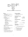
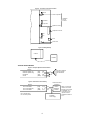
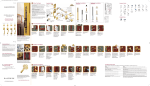
Refer to Figure 1 for a simplified block diagram of a
typical installation.
947301A
E-Key
C.O.Line
Position
Doorplate
Speaker
with
Pushbutton
V-2901A
Universal
Door
Answering
System
Power
Supply
FIGURE 1
SIMPLIFIED BLOCK DIAGRAM OF A TYPICAL INSTALLATION
Features
Dimensions/Weight
Compatible with PABX, E-Key and 1A2
telephone systems
Switch selectable - loop or ground start access
Provides handsfree talkback
RJ11 modular connector for Tip and Ring
connections
Power ON LED
Provides door unlock contacts
Programmable options:
Programming access code
Ring pattern
Activate lock relay
Duration of lock relay activation
Time door can remain open after unlock
(exit delay time)
Entry delay time
Duration of ringing
Disable station alarm
Alarm disable code
Station alert tone
Input for manual door unlock (push-button)
Built-in 30Hz ring voltage generator with on/off
switch
Ringback tone to speaker
Calls can be placed On Hold
Background music input with volume control
Speaker to phone volume control
Phone to speaker volume control
Confirmation tone
Compatible with tone dial phones
Works with Valcom V-1072A doorplate speaker
or other Valcom talkback or doorplate speakers
Compatible with VPB-260 battery backup
8.60"H x 11.00"W x 2.30"D
(21.84cm H x 27.94cm W x 5.84cm D)
3.0 lbs. (1.36 kg)
Nominal Specifications
Input Impedance:
Input Level:
Output Impedance:
Ring Supply:
600 Ohms
-10dBm Nominal
45 Ohms
90VAC, 30Hz
Power Requirements
Power Supply:
-24VDC filtered
600mA minimum
Environment
Temperature:
Humidity:
0 to +40°C
0 to 85% (non-precipitating)
Components
The following equipment is recommended when
using the V-2901A:
2
1 - V-2901A Universal Door Answering System
1 - C. O. Line Position (Electronic Key
System);
or
1 - Loop Trunk Position (PABX); or
1 - 400 type line card (1A2 key)
1 - Dedicated single line phone*
1 - Valcom Doorplate Speaker**
1 - VP-624B Power Supply
gateway, window or secure room - just to name a
few.
* A single line telephone cannot be connected to
both the V-2901A and an incoming central office
line.
INSTALLATION
** It is recommended that one talkback speaker
be used. Use of more than one talkback speaker
may result in damage to the V-2901A. Up to 40
one-way amplified speakers may be connected to
the V-2901A speaker output.
Cabling
A 25 pair cable with a female amphenol connector
should be run from the V-2901A to a 66 block. The
cables should be terminated on the connecting block
in standard color code. Refer to Figure 2 - Block
Connections for the pinout locations.
DESIGN
The V-2901A, Universal Door Answering System,
was designed to provide voice paging with handsfree
reply to a door speaker from a telephone location.
The
V-2901A initiates ring-in on the telephone
system and sends a confirmation tone to the door
when a button is pressed at the door (Valcom
doorplate speakers are normally used in this
application). The individual at the phone responding
to the signal can converse with the person at the door
and determine if access should be allowed. If the
door is equipped with an electric strikeplate, the
person at the phone can enter a programmed code on
the telephone dialpad or press a remote button to
unlock the door to allow admission. A call to the
door may also be initiated from the telephone system.
The V-2901A provides an alarm control output for
unauthorized entry. When the door lock relay is
activated and the door remains open longer than the
programmed period of time, a ground potential will
appear on pin 3 of the V-2901A (unauthorized door
opening) that can be used to signal a customer
provided alarm, auto dialer, etc. Also, if the phone is
on hook, the phone will begin ringing in a single
burst pattern. If the phone is off hook, it will receive
a momentary warble tone. After hang-up, if the door
is not closed, the alarm condition will continue.
Mounting
The V-2901A is designed to be wall or shelf
mounted. When wall mounting the V-2901A, secure
the unit to wall studs or a suitable brace, away from
heat sources or strong magnetic fields (motors, fans,
power supplies, etc.) with controls and connectors
accessible. (A plywood backboard two feet square
and at least 1/2 inch thick attached to wall studs
would be considered a suitable brace).
Four #10 x 3/4 inch flat-head wood screws are
included for mounting. Fasten two screws on the
mounting surface, allowing them to protrude 1/8 inch
to 1/4 inch. Place the chassis of the V-2901A onto
the screwheads at the mounting slots. Position the
remaining screws and fasten through the remaining
mounting slots. Tighten screws.
Connections
Mount a 66 block on the backboard near the
V-2901A Universal Door Answering System and
label the block per Figure 2.
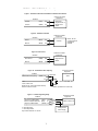
Move slide switch SW2 on the V-2901A to the
appropriate location, Loop or Ground Start, (see
Figure 3) depending on how the V-2901A is
accessed.
When indication arrives that a door is open while
door station is inactive, such as a break-in, the system
waits the programmed period of time (entry delay
time) for a confirmation of entry indicating the
opening as legitimate. When this does not arrive in
the programmed time frame or if it arrives and the
door is not closed at the end of the programmed time
period, an alarm will sound in the same manner as
described above.
The V-2901A also provides a background music
input and is designed to automatically mute music
during a page. If background music is to be installed,
a low level music source such as the Valcom V-2952
FM Tuner will be required.
Applications for the V-2901A includes a doorway,
3
If a modular cord is used for Tip and Ring
connections, start at step ONE. For 66 block
connections start at step TWO.
___ 1.
Connect one end of the modular cord to the
V-2901A RJ11 and the other end to the
appropriate line position of the phone
system. Go to step 3.
___ 2.
Connect Tip of the key system line position,
loop or ground start trunk, to Pin 26 (W/BL)
and Ring to Pin 1 (BL/W).
___ 3.
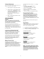
Connect Tip of a 45 Ohm talkback speaker
to pin 32 (R/O) and Ring to pin 7 (O/R).
___ 4.
If using a door button with the talkback
speaker, connect normally open, single pole
push-button switch to Door Button
connection pin 33 (R/G) and pin 9 (BR/R)
Ground. (Figure 5 depicts the speaker/door
button hookup).
___ 5.
Move slide switch SW1 (located on the
V-2901A board) to the ON position if the
telephone system is to ring when the door
button is pressed. (Refer to Figure 3 for
location).
___ 6.
NOTE: If the remote button does not
respond, you have most likely entered a
confirmation press. Any immediate
additional presses will result in an alarm
condition.
Handsfree Indicator ("Station
Outputs")
Connect the -24VDC power supply. 24VDC should be connected to pin 25 (S/V)
and Ground connected to pin 50 (V/S). The
power LED located on the V-2901A board
should illuminate.
Battery Backup
A Valcom VPB-260 Battery Backup may be added to
the system to provide power in case of power failure.
The VPB-260 plugs directly into the V-2901A.
Figure 4 shows the appropriate connection. The
VPB-260 should be allowed to charge for
approximately 9 hours before operating the V-2901A.
The Valcom VPB-260 battery backup may be
used as the sole supply of power to the V-2901A.
The V-2901A supplies connections to allow a
handsfree indicator to be connected to the system.
During handsfree communication, pin 6 goes to
-24VDC when connected as shown in Figure 8.
Maximum current available is 50mA.
Door Sensor
When this contact is shorted (opening the door, gate
etc) without a legitimate dialpad or remote key press
opening, this will initiate an alarm condition. Refer
to Figure 9 for typical connections.
Unauthorized Door Opening
During an alarm state, UDO (unauthorized door
opening) goes to ground, to signal a customer
provided alarm that an alarm condition exists. Refer
to Figure 10 for typical connections.
Remote Signaling (Alerting Device)
The V-2901A supplies contacts to allow an alerting
device to be connected to the system. These contacts
follow the ringing cycle (except when using British
Ring - see note page 8) and can be used to operate a
remote signaling device such as a bell, buzzer or
light. Refer to Figure 11 for a typical connection
using these contacts.
Remote Door Unlock Relay
Figure 6 shows the V-2901A contact arrangement
available for electric strike plate operation.
Before connecting an electric lock to the V-2901A,
consult the manufacturer instructions for the proper
connecting arrangement.
Background Music Connections
Connect the low level (-10dBm nominal) output of a
music source to pin 29 (W/BR) and pin 4 (BR/W) of
the 66 block. Adjust output of the music source to a
low level. Volume of the background music will be
regulated by the music volume control of the V2901A.
Remote Push-button for Manual Door
Release
A momentary, normally open, single-pole,
single-throw switch can be connected to the system.
Pinouts to the 66 block are shown in Figure 7. Refer
to manufacturer instructions for proper connections.
The remote button should be placed in an
inconspicuous location to provide a more secure
system.
4
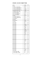
FIGURE 2 - BLOCK CONNECTIONS
Tip
Ring
Common Audible Make
Common Audible Stationary
Common Audible Break
Unauthorized Door Opening
Background Music Tip
Background Music Ring
Door Unlock Make
Door Unlock Stationary
Door Unlock Break
Station
Handsfree Speaker Tip
Handsfree Speaker Ring
Door Button
Remote
Door Sensor
Ground
Not Used
Not Used
Not Used
Not Used
Not Used
Not Used
Not Used
Not Used
Not Used
Not Used
Not Used
Not Used
Not Used
Not Used
Not Used
Not Used
Not Used
Not Used
Not Used
Not Used
Not Used
Not Used
Not Used
Not Used
Not Used
Not Used
Not Used
Not Used
Not Used
Not Used
Power Supply GND
Power Supply -24VDC
5
W/BL
BL/W
W/O
O/W
W/GR
GR/W
W/BR
BR/W
W/S
S/W
R/BL
BL/R
R/O
O/R
R/G
G/R
R/BR
BR/R
R/S
S/R
BK/BL
BL/BK
BK/O
O/BK
BK/G
G/BK
BK/BR
BR/BK
BK/S
S/BK
Y/BL
BL/Y
Y/O
O/Y
Y/G
G/Y
Y/BR
BR/Y
Y/S
S/Y
V/BL
BL/V
V/O
O/V
V/G
G/V
V/BR
BR/V
V/S
S/V
26
1
27
2
28
3
29
4
30
5
31
6
32
7
33
8
34
9
35
10
36
11
37
12
38
13
39
14
40
15
41
16
42
17
43
18
44
19
45
20
46
21
47
22
48
23
49
24
50
25
Figure 3 - Connector and Control Locations
Music
Phone to Speaker
Handsfree
Volume
Controls
Gnd Start
Loop Start
SW2
Speaker to Phone
Amphenol Connector
Off
On
Ringer
SW1
RJ11
Power LED
Figure 4 - Battery Backup
V-2901A
VPB-260
TYPICAL APPLICATIONS
Figure 5 - Doorplate Speaker with Pushbutton
66 Block
Handsfree Speaker Tip
Handsfree Speaker Ring
Door Button
Ground
(R/O)
(O/R)
(R/G)
(BR/R)
P 32
P 7
P 33
P 9
PB
Figure 6 - Remote Door Unlock Relay
Customer Provided
Equipment
66 Block
Door Unlock Make
Door Unlock Stationary
Door Unlock Break
(W/S)
(S/W)
(R/BL)
P 30
P 5
P 31
NO = Normally Open
NC = Normally Closed
Handsfree Talkback
45 ohm Speaker
with Pushbutton
T
R
NO
Com
NC
Electric
Strikeplate
Solenoid
Strikeplate
Power Supply
6
NOTE: Consult manfacturer's connection
diagram for connection
of strikeplate. N. C.
connection may be
required on some
strikeplates instead of
N.O.
TYPICAL APPLICATIONS (Continued)
Figure 7 - Remote/Confirmation Pushbutton for Manual Door Release
Customer Provided
Equipment
66 Block
Remote
(G/R)
P8
Ground
(BR/R)
P9
Momentary
Single Pole, N. O.
Single Throw
Switch
Figure 8 - Handsfree Indicator
Customer Provided
Equipment
66 Block
Station
(BL/R)
P6
-
Ground
(BR/R)
P9
+
Indicator
Figure 9 - Door Sensor
Customer Provided
Equipment
66 Block
Door Sensor
(R/BR)
P34
Ground
(BR/R)
P9
Magnetic Door
Switch
Figure 10 - Unauthorized Door Opening
Customer Provided
Equipment
66 Block
Unauthorized Door Opening
50mA, -24 Vdc
current maximum
available for
indicator
(GR/W) P 3
Signal Out
Alarm
-24 Vdc
To Alarm, auto dialer, etc.
-24 Vdc, 125mA max
* Signal out only, will not drive alarm directly
** Ground must be common
Customer provided low current relay
Figure 11 - Remote Signalling Relay
Customer Provided
Equipment
66 Block
Commmon Audible Make
Common Audible Stationary
Common Audible Break
(W/O)
P27
(O/W)
P 2
(W/GR) P28
NO = Normally Open
NC = Normally Closed
Relay contacts rated at 1A –24 Vdc
NO
Com
NC
Bells, buzzers, etc.
Alerting Device
Power Supply
7
Volume Adjustments
There are four volume controls on the V-2901A. See
Figure 3 for location of these controls.
___ 1.
Phone to Speaker: Adjusts speaker volume.
___ 2.
Speaker to Phone: Adjusts talkback volume
from the speaker. IMPORTANT: Set this
volume at the lowest practical level. Setting
this control too high will increase
background noise without giving greater
talkback volume.
___ 3.
Music: Adjusts Background Music volume
at the door speaker.
PROGRAMMING
General
The default master access code is 1 2 3. To change
this code:
1. Lift handset, press # and hear dial tone.
2. Press # # # on the dialpad.
3. Enter the old access code on the dialpad.
4. Press * * * on the dialpad.
5. Enter the new access code on the dialpad.
6. Press * * * again.
7. Will receive dial tone if programmed correctly.
Programming Functions
The following program instructions show the
access code for each function as 1 2 3. If a new
master access code is programmed prior to
programming the following functions, the new
access code would be substituted where the 1 2 3 is
shown.
These following codes cannot contain # as part of
their code.
NOTE: The V-2901A can be accessed via
tone dial systems and programming must be
performed with a tone dial set.
Ring Pattern
The V-2901A is designed to allow the user to
program its functions to meet the requirements of the
specific application. The V-2901A is; however,
shipped from the factory with the all functions pre-set
to default settings. These default settings are listed in
the Program Chart.
It is strongly recommended that the default
settings be changed to suit the needs of the
situation. The settings of the Access Code and
Door Unlock Code, particularly, should be
changed to provide a more secure system.
When the doorplate button at a station is pressed, the
V-2901A initiates ring-in on the telephone system.
There are three ring patterns available.
2 seconds on, 4 seconds off (American ring)
2 bursts in 2 seconds, 2 seconds off (British ring)
1 second on, 4 seconds off (Dutch ring)
To change the ring pattern:
American Ring (default)
1. Lift handset, press # and hear dial tone.
2. Press # 1 2 3 * 5 on the dialpad.
3. Receive dial tone.
The following instructions explain the procedures to
program the codes for the V-2901A. Individual
codes can be programmed per feature. After each
program change, a dial tone will be received
designating a proper entry.
British Ring
1. Lift handset, press # and hear dial tone.
2. Press # 1 2 3 * 6 on the dialpad.
3. Receive dial tone.
Master Access Code
The Master Access Code allows entry to
programming as well as to the use of the system. It is
essential that this code remain confidential to
maintain the security of the system. The Access
Code can be 1 to 7 digits in length. The asterisk (*)
or number (#) signs can not be used in the access
code.
8
Dutch Ring
1. Lift handset, press # and hear dial tone.
2. Press # 1 2 3 * # on the dialpad.
3. Receive dial tone.
NOTE: The common audible relay contacts
follow the ringing cadence with the exception
of British Ring. In British Ring mode, the
contacts close at the beginning of the first
burst and remain closed until the end of the
second burst.
Activate Lock Relay (Door Unlock)
This code would be used to operate the door unlock
contacts which can be used to open an electric lock
used at a doorway or gate. The default access code to
activate the lock relay is *. This code can be from 1
to 7 digits and the asterisk (*) sign can be
programmed in this code if desired.
To change this code:
1. Lift handset, dial # to hear dial tone.
2. Press # 1 2 3 # on the dialpad.
3. Press 1.
4. Enter up to 7 digits.
5. Press #.
6. Receive dial tone.
If a key entry occurs at the door (an entry not using
the dialpad or remote button), the remote button must
be pressed or the confirmation code must be dialed on
the telephone keypad within a designated period of
time after the door is opened, signifying a legitimate
door opening, or the V-2901A will go into alarm
mode. The default time for the confirmation press is
15 seconds. This time can be changed by:
1. Lift handset, press # to hear dial tone.
2. Press # 1 2 3 # 8.
3. Enter time length in seconds (0-999).
4. Press #.
5. Receive dial tone.
Duration of Ring
Duration of Lock Relay Activation
This function determines the length of time the lock
relay remains activated after dialing the door unlock
code. The default equals two seconds. The length of
time the lock relay remains activated can be from one
to 99 seconds depending on the specific situation.
However, once an opening and closing of a door
takes place, the unlock relay will release prior to the
expiration of the programmed period preventing
further entries.
To change this default setting:
1. Lift handset, dial # to hear dial tone.
2. Press # 1 2 3 # 6 on the dialpad.
3. Enter the number of seconds the lock should
remain activated (1-99).
4. Press #.
5. Receive dial tone.
Time Door May Remain Open after
Unlock before Alarm (this period of time
also sets the exit delay time)
The length of time the door or gate should remain
open will vary depending on the actual application.
A drive-through gate may require a longer time than a
walk-through door. If, for some reason, the opening
does not close by the designated period of time, an
alarm condition will occur (see Operation). The
possible programmed time for a door to remain open
can be from 0 to 999 seconds. The default for this
function is 15 seconds. This default is changed by:
1. Lift handset, press # to hear dial tone.
2. Press # 1 2 3 # 7 on the dial pad.
3. Enter the number of seconds the door should
remain open (0-999).
4. Press #.
5. Hear dial tone.
Entry Delay Time
9
When the door button is pressed, it activates the
phone into a ring cycle. The ring cycle will continue
for a programmed duration and stop if unanswered.
The default equals 30 seconds. To change this
default:
1. Lift handset, press # receive dial tone.
2. Press # 1 2 3 # 5.
3. Enter the duration of ringing desired
(1 - 255 seconds; 0 = continuous).
4. Press #.
5. Receive dial tone.
Disable Station Alarm
On power up, the station alarm condition is active. In
the event a doorway or gate would need to be left
open for an extended time (or at least longer than the
programmed time it can remain open before an alarm
condition), the alarm can be disabled.
To leave door open without causing an alarm
condition:
1. Lift handset, press # and receive dial tone.
2. Press 5.
3. Enter disable code (default is *; this may have
been changed - see below).
4. Receive dial tone.
The default code for disabling the station alarm
condition is *. To change this default:
1. Lift handset, press # and hear dial tone.
2. Press # 1 2 3 *.
3. Enter up to 7 digits.
4. Press #.
5. Receive dial tone.
NOTE: When the station is disabled and then
accessed, the alert tone will be at a lower pitch as a
reminder that the station alarm has been disabled.
To enable the door alarm after it has been disabled:
1. Lift handset, press # to receive dial tone.
2. Press 6.
3. Receive dial tone.
the phone will receive a momentary warble tone and
will be connected to the station. After hang up, if the
door is not closed, the alarm condition will continue.
When an indication arrives that the door is open
while the door station is inactive, (example: a
break-in) the system waits the programmed period of
time for a confirmation of entry, if the confirmation
of entry is not received, the unauthorized entry alarm
will take place as described previously.
Alert Tone
The phone and station receives a ringback tone prior
to connection. Default the station receives the tone.
To remove the alert tone:
1. Lift handset, press # and receive dial tone.
2. Press # 1 2 3 # 9.
3. Press 0.
4. Press #.
5. Receive dial tone.
Confirmation of Entry
When a key entry is made (an entry not using the
dialpad or remote button), either the remote button
must be pressed (a confirmation press) within the
programmed period of time after the door is opened
or the telephone can be used to dial the appropriate
confirmation of entry. To confirm an entry by phone,
access the V-2901A and enter door unlock code.
To re-activate the alert tone:
1. Lift handset, press # and receive dial tone.
2. Press # 1 2 3 # 9.
3. Press 1.
4. Press #.
5. Receive dial tone.
Door Detect
Some door alarm contacts are closed when the door is
closed and some are open when the door is closed.
By default, the V-2901A uses door alarm contacts
that are open when the door is closed.
To change this default:
1. Lift handset, press # and hear dial tone.
2. Press # 1 2 3 # 0 1.
3. Press # and receive dial tone.
OPERATION
When the doorplate button is pressed, interrupted ring
voltage from the V-2901A initiates ring-in on the
telephone system and sends a confirmation tone to the
door. When the phone is answered, the ringing is
removed, the phone receives a ringback tone and is
connected to the handsfree speaker.
If the door is equipped with an electric strikeplate, a
code can be dialed from the phone to operate the
relay used to unlock the door. The lock relay will
remain open for a programmed period of time. A
normally open, single-pole push-button switch can
also be connected to the V-2901A to manually
operate the door unlock relay. The lock relay will
remain open as long as the remote button is held
(maximum 99 seconds) plus the programmed period
of time.
A confirmation press or entering the unlock code via
telephone to signify a legitimate door opening must
take place before the programmed period of time ends
or an alarm condition will occur.
NOTE: The remote button can be used for a
confirmation press or to activate the lock relay
(door unlock).
Exiting without Alarm Activation
1. Lift handset and enter door unlock code or press
manual door unlock push-button.
2. Exit door within the programmed exit delay time.
Exit delay time equals time door unlock relay is
activated after unlock.
Call Out from the Phone
The dedicated single line telephone, C.O. line
position, loop or ground start trunk used with the
V-2901A is dedicated to the door communications
and to features accessed within the V-2901A system.
The phone can be used to access the speaker station
by going offhook or by accessing the C. O. line
position or trunk port that is connected to the
V-2901A. A ringback tone (optional) will be
generated prior to connection to the station.
A telephone connection with the station can be
terminated by hanging up or pressing the # sign.
After the lock relay has closed, if the door remains
open longer than the programmed time, and a
customer supplied door sensor is provided, an alarm
condition will occur. If on hook, the phone will
begin ringing in a pattern indicating that the door has
failed to close and the UDO (Unauthorized Door
Opening) output goes to ground. When answered,
10
VALCOM equipment is not field repairable.
VALCOM maintains service facilities in Roanoke,
VA. Should repairs be necessary, attach a tag to the
unit clearly stating your company name, address,
phone number, contact person and the nature of the
problem. Send the unit to:
TECHNICAL ASSISTANCE
When trouble is reported, make certain there are no
broken connections leading to this system. Table 1
identifies some possible problems with solutions.
Assistance in troubleshooting is available from the
factory. When calling, you should have a VOM and
a telephone test set available and be calling from the
job site. Call (540) 563-2000 and press 1 for
Technical Support or visit our website at
http://www.valcom.com.
Repair and Return Dept.
VALCOM, INC.
5614 Hollins Road
Roanoke, VA 24019-5056
USER GUIDE
Function
Action
Unlock Door
Dial unlock code (or press remote push-button).
Disable Alarm
Dial # to receive dial tone, dial 5 and the alarm disable code.
Enable Alarm
Dial # to receive dial tone, dial 6.
Exiting with Alarm On
Access system and dial unlock code (or press remote push-button),
then exit door within exit delay time.
Entering with Alarm On
Enter door, then dial door unlock code (or press remote push-button)
within entry delay time.
TABLE 1
TROUBLESHOOTING CHART
PROBLEM
ACTION
No system operation; power LED not lit
Verify power from power supply.
No system operation; power LED is lit
Verify that 25 pair connector is completely
plugged into circuit board connector.
Refer to the Connection section and verify all
connections.
No paging at speaker
Check doorplate speaker connections.
Adjust phone to speaker volume.
Paging at speaker but no reply from speaker
Adjust speaker to phone volume.
No system ringing when doorplate button is
pressed
Check ring ON/OFF switch.
Door unlock relay does not operate
Check connections at block.
Verify proper access code.
Door strike does not operate
Do you have a power supply for your door strike?
(See Figure 6).
11
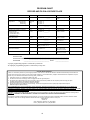
PROGRAM CHART
RECORD AND FILE IN A SECURE PLACE
FUNCTION
DEFAULT
REPROGRAM
PARAMETER
Master Access Code (MAC)
1 2 3
# # # # 1 2 3 * * *______* * *
7 digits excluding
# and *
Ring Pattern
American
Ring
# # MAC * 5
# # MAC * 6
# # MAC * #
Activate Lock Relay
*
# # MAC #1 ________ #
7 digits including *
Duration of Lock Relay Activation
2 sec
# # MAC #6________ #
1-99 in seconds
Time Door May
Remain Open After
Unlock Before Alert
(Exit Delay Time)
15 sec
# # MAC #7________ #
0-999 in seconds
Entry Delay Time
15 sec
# # MAC #8________ #
0-999 in seconds
Duration of Ringing
30 sec
# # MAC #5________ #
1-255 sec;
0 = continuous
Alarm Disable Code
*
# * MAC *1________ #
7 Digits
Alert Tone
ON
[OFF] # # MAC # 90 #
[ON] # # MAC # 91 #
OFF or ON
Door Detect Default
# # MAC # 0 0
Door contact open
when door is closed.
Door Detect Reversed
# # MAC # 0 1
Door contact closed
when door is closed.
American Ring
British Ring
Dutch Ring
INSTALLATION
____________________________________________________________________________
INSTALLING COMPANY
INSTALLER
NEW PROGRAM
___________________________________________________________________
___________________________________________ DATE
______________________
A proper programming sequence is followed by a dial tone.
An improper programming sequence is followed by a busy tone.
VALCOM LIMITED WARRANTY
Valcom, Inc. warrants its products only to the original purchaser, for its own use, to be free from defects in materials and workmanship under conditions of
normal use and service for a period of one year from the date of shipment. This Limited Warranty obligation shall be limited to the replacement, repair or
refund of any such defective device within the warranty period, provided that:
1. inspection by Valcom, Inc. indicates the validity of the claim;
2. the defect is not the result of damage, misuse or negligence after the original shipment;
3. the product has not been altered in any way or repaired by others and that factory sealed units are unopened (a service charge plus parts
and labor will be applied to units defaced or physically damaged);
4. freight charges for the return of products to Valcom are prepaid;
5. all units 'out of warranty' are subject to a service charge. The service charge will cover minor repairs (major repairs will be subject to
additional charges for parts and labor).
This Limited Warranty is in lieu of and excludes all other warranties, expressed or implied and in no event shall Valcom, Inc. be liable for any
anticipated profits, consequential damages, loss of time or other losses incurred by the buyer in connection with the purchase, operation,
maintenance, installation, removal or use of the product. The maximum liability of Valcom under this warranty is limited to the purchase price of the
specific Product covered by the warranty.
Disclaimer. Except for the Limited Warranty provided herein, the product is provided “as-is” without any warranty of any kind whatsoever including, without
limitation, any WARRANTY OF MERCHANTABILITY, FITNESS FOR A PARTICULAR PURPOSE OR NON-INFRINGEMENT.
This warranty specifically excludes damage incurred in shipment. In the event a product is received in damaged condition, the carrier should be notified
immediately. Claims for such damage should be filed with the carrier involved in accordance with the F.O.B. point.
Headquarters:
Valcom, Inc.
5614 Hollins Road Roanoke, VA 24019-5056
Phone: (540) 563-2000 FAX: (540) 362-9800
12