1
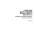
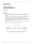
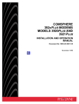
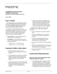
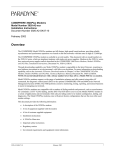
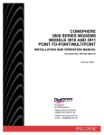
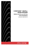
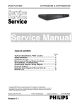
TM
COMSPHERE 392xPlus Modems
Models 3920Plus and 3921Plus
Firmware Update Description
Document Number 3920-A2-GK62-10
November 1996
Overview
This document describes new and changed information in the Model 3920Plus and 3921Plus modems as a result
of the Firmware Release 3.1. Use this document in conjunction with the COMSPHERE 392xPlus Modems,
Models 3920Plus and 3921Plus, Technical Reference Manual, Document No. 3920-A2-GH30.
Device Health and Status (DeviceHS)
The following Health and Status messages are new to Table 3-6, Health and Status Messages, beginning on
page 3-18.
Table 3-6
Health and Status Messages
Type
Major
j
3920-A2-GK62-10
Message
Indicates
External Alarm A
External input A to Port 4 of the modem is in an alarm condition.
External Alarm B
External input B to Port 4 of the modem is in an alarm condition.
November 1996
1
Status Branch
SDC (Synchronous Data Compression) is a new addition to the Status branch menu on page 3-17.
“Status”
PList
Configure
Control
Test
SubHS
SDC
V.34
Call_Setup
Tlk/Data
Security
Remote
Status
Port
Select
DeviceHS
Major
Minor
Status
Dial
Thresh
Security
Port1
Port2
Port3
Port4
2
VF
Display
Identity
Clear
SigQual
RcvLevel
Sig/Noise
NrEchLvl
FarEchLv
FarEchDel
EchoFreqOff
Phase Hts
Impul Hts
DropOuts
Retrains
Phas Jtr
NonLinear
FreqOffset
Gain Hts
Ser#
Mod#
FRev
HPt#
FPt#
Country
DTE
LSD
DTR
DSR
Tst
TXD
RXD
RTS
CTS
Tx
Rx
DTE Rate
Cmp Ratio
Efficiency
TxRate
RxRate
SymbolRate
Tx Level
AsymRate
November 1996
Backup
Options
Line = Pri 4W APL
Line = Pri 2W APL
Line = Bkup 2W APL
Line = Dial Backup
Line = Dial ONLY
Line = No Sync
Record
Service_Log
Display
Clear
3920-A2-GK62-10
SDC
When running synchronous data compression, the SDC function displays information about the modem’s
transmitting and receiving DTE rate, compression ratio, and line efficiency.
To access SDC from the Status branch, make the following selections:
Status:
SDC
F1
V.34
F2
F3
Select SDC.
SDC Performance:
Tx
Rx
F1
F2
F3
Select either Tx (transmit) or Rx (receive).
SDC Perf: Rx
>
DTE Rate
nnnnnn
F1
F2
F3
The DTE Rate appears for the selected SDC Performance Tx or Rx. Press the
key to view the SDC
performance for DTE rate, compression ratio, and line efficiency measurements (see Table 1 for additional
information).
3920-A2-GK62-10
November 1996
3
Table 1
SDC Performance Measurements
DTE Rate
Compression Ratio
Line Efficiency
Tx
The number of bits per second
received from the DTE. This
number takes into account only
the data between the opening and
closing flags of the HDLC frames.
Flags and DTE interframe time fill
are ignored.
The ratio between the number of
bits in the input and output of the
compression algorithm. The
calculation does not include the
overhead of the LAPM frame or
the DTE flags and DTE
interframe time fill.
The ratio between the number of
bits per second sent on the line,
and the line rate. The calculation
does not include the DCE
interframe time fill.
Rx
The number of bits per second
sent to the DTE. This number
takes into account only the data
between the opening and closing
flags of the HDLC frames. Flags
and DTE interframe time fill are
ignored.
The ratio between the number of
bits in the output and input of the
decompression algorithm. The
calculation does not include the
overhead of the LAPM frame or
the DTE flags and DTE
interframe time fill.
The ratio between the number of
bits per second received from
the line, and the line rate. The
calculation does not include the
DCE interframe time fill.
Group
Multiport Mode
The Multiport Mode configuration branch tree on page 4-9 has the following additions:
• Port4 Ext Alarm
• V34 Symbol Rate
• V.34 Precoder
• Rate Auto Orig
• SpecialSecurity
• EntryWait_Time
• VF_Prompt Type
4
November 1996
3920-A2-GK62-10
Multiport Mode ✫
DTE
Interface
DTE
Dialer
Line
Dialer
AutoAnswerRing#
Dialer Type
DialTone Detect
Blind Dial Paus
BusyTone Detect
"," Pause Time
NoAnswer Timout
Fast Disconnect
Line Crnt Disc
Long Space Disc
No Carrier Disc
No Data Disc
Auto Make Busy
MUX
MUX Mode
–TDM/MSD
–DTE Bridge
Tx Clock Source
Port4 Ext Alarm
Bakup_TXClk_Src
CT111_Rate Cntl
MSD Port Control
Copy
Dial
Line
Dial Modulation
Dial Line Rate
Autorate
V32bis Override
Dial Tx Level
Train Time
V34 Symbol Rate
V.34 Precoder
Asymmetric Rate
LeaseModulation
LeasedLine Rate
Leased Mode
Autorate
V32bis Override
Leased Tx Level
Asymmetric Rate
2 Sec LSD Hold
Auto Dial Back
Rate Auto Orig
AutoDialStandby
SpecialStandby
DialStandbyTime
CarrierOn Level
TMp Train Time
TMp Tx Preemphis
TMp TxPre-Value
Lease Lookback
Dual_Leased_Ln
BackupLine Check
Test
Test Timeout
V54 Address
V54 Device Type
Misc
Security
StrapsWhenDisc
Speaker Control
Speaker Volume
Access frm Remt
RemAccssPasswrd
Dir#1_Callback
SpecialSecurity
EntryWait_Time
VF_Prompt Type
NMS_Call_Msgs
NetworkPosition
NetMngmtAddress
Diag Connection
Mixed Trib F/W
Link Delay(sec)
Port 1 Port 2* Port 3* Port 4*
From Port X
To Port X or All
Rate*
Port MSD Mode
Rate at 33.6 K
Rate at 28.8 K
Rate at 24.0 K
Rate at 19.2 K
Rate at 16.8 K
Rate at 14.4 K
Rate at 12.0 K
Rate at 9600
Rate at 7200
Rate at 4800
Rate at 2400
Async
Async/Sync Mode
Async DTE Rate
Asyn #Data Bits
Asyn #Stop Bits
Async OverSpeed
*Not shown when the DTE Bridge configuration option is enabled.
3920-A2-GK62-10
V.42/
MNP/
Buffer
Leased_Line
November 1996
EIA
DTR Action
DSR Control
RTS Action
RTS Antistream
CTS Control
RTS/CTS Delay
LSD Control
XTXC Clamps TXC
CT111 Control
Rcv Remote Loop
DTE RL (CT140)
DTE LL (CT141)
Port TXC Source
DTE Alarm Mask
Extend Main Ch.
Upstream Port
496-14623-03
5
DTE Interface – Multiport Mode
The following information is new or changed in Table 4-1, DTE Interface Configuration Options – Multiport
Mode, beginning on page 4-10.
MUX Sub-Group
Port4 Ext Alarm: Disable
Nxt Disable EnableLow EnableHigh
This configuration option only appears when MUX Mode is configured for TDM/MSD.
Port 4 External Alarm Monitor. Determines if Port 4 can be used to transmit user data. When enabled, this configuration
option prevents Port 4 of the modem from being used to transmit user data. Instead, inputs on Pins 18 (external
Alarm B) and 21 (External Alarm A) on Port 4 are used to monitor an external device for alarms (such as a power supply
that can generate alarm status signals that are compatible with RS-232 levels). Once this configuration option is
enabled and saved, all Port 4 configuration options become inaccessible. Also, all Port 4 rate configuration options are
automatically disabled, and the DTE RL (CT140) and DTE LL (CT 141) configuration options are automatically set to
Disabled.
Disable – Port 4 of the TDM can be used for user data.
EnableLow – Port 4 of the TDM can only be used to monitor for external alarms. Low input signals are alarms, and high
input signals are normal.
EnableHigh – Port 4 of the TDM can only be used to monitor for external alarms. High input signals are alarms, and low
input signals are normal.
Port Async Sub-Group (One for Each Port)
Async/Sync Mode: Sync
Nxt Sync Async
Asynchronous/Synchronous Mode. Determines whether the port operates in Asynchronous mode or Synchronous
mode.
NOTE: When using the TMp or Sync factory templates and MUX Mode is disabled, Port 1 is set to Sync mode.
Port EIA Sub-Group (One for Each Port)
XTXC Clamps TXC: Enable
Nxt Enable Disable
This configuration option only appears when the TX Clock Source or Bakup_TXClk_Src configuration option is
set to Port 1, 2, 3, or 4 and Async/Sync mode is Sync.
External Transmit Clock Clamps Transmit Clock. Allows the port’s TXC output (Pin 15 on the EIA-232-D interface) to be
clamped OFF when TX Clock Source is configured for Port 1, 2, 3, or 4.
Enable – TXC is clamped OFF when TX Clock Source is configured for Port 1, 2, 3, or 4.
Disable – TXC continues to be provided when TX Clock Source is configured for Port 1, 2, 3, or 4.
DTE Alarm Mask: Disable
Nxt Disable Enable
DTE Alarm Mask. Allows you to enable or disable the reporting of DTE alarms (in Singleport mode only) to the front
panel and/or the NMS.
Disable – Reports alarms.
Enable – Does not report alarms.
6
November 1996
3920-A2-GK62-10
Dial Line – Multiport Mode
The following information is new or changed in Table 4-3, Dial Line Configuration Options – Multiport Mode,
beginning on page 4-21.
Autorate: Enable
Nxt Enable Disable StartAt48 StartAt96 Fast
Autorate. Once connected, the modem automatically lowers the line rate if line conditions become impaired. When line
conditions improve, the modem automatically shifts up to the highest data rate the line can support. Autorate only
occurs between 19,200 bps and 4800 bps during V.32, V.32bis, and V.32 terbo connections and 33.6 and 2400 bps for
the V.34 family.
Start at 48 and Start at 96 – Set the maximum connect rate for V.32, V.32bis, and V.32 terbo connections.
Fast – Autorate is enabled and tuned to minimize bit errors.
V34 Symbol Rate: Automatic
Nxt Automatic 3429H 3429L 3200L 3200H 3000L 3000H 2800L 2800H 2743L 2743H 2400L 2400H
This configuration option only appears when V.34 is enabled.
V.34 Symbol Rate. Selects the symbol (or baud) rate to be used when operating with V.34 modulation on either dial or
leased lines.
Automatic – The modem automatically determines the top symbol rate that can be supported by the current line
conditions. This is the only setting that is compliant with the V.34 specification, and should not be changed unless
unusual line conditions exist.
3429L, 3200L, 3000L, 2800L, 2743L, 2400L – Fixed symbol rate with low carrier signal.
3429H, 3200H, 3000H, 2800H, 2743H, 2400H – Fixed symbol rate with high carrier signal (100 Hz above low carrier
signal).
V.34 Precoder: Disable
Nxt Disable Enable
This configuration option only appears when V.34 is enabled.
V.34 Precoder. Determines whether the V.34 Precoder is used when operating with V.34 family modulation on either dial
or leased lines. The V.34 Precoder improves performance under certain unusual line conditions, i.e., low harmonic
distortion, single frequency interference.
Disable – Do not use the V.34 Precoder.
Enable – Use the V.34 Precoder.
Asymmetric Rate: Disabled
End Enable Disable
This configuration option only appears when V.34 is enabled.
Asymmetric Rate. Controls rate symmetry when running V.34 modulation by enabling or disabling the V.34 modulation
from using equal transmit and receive rates.
Enable – The modem operates in asymmetric rate mode (the transmit and receive rates can be different) when running
V.34 modulation. The Asymmetric Rate configuration option must be enabled in both modems.
Disable – The modem operates in symmetric rate mode (the transmit and receive rates are identical) when running V.34
modulation. Either modem can force symmetric mode by disabling the Asymmetric Rate configuration option.
NOTE: This configuration option is typically disabled when the MUX is in use, and it is enabled when the MUX is disabled.
If you are using a factory template that has the MUX enabled, and then you manually disable the MUX, you must
verify that this configuration option is set to the correct value.
3920-A2-GK62-10
November 1996
7
Leased Line – Multiport Mode
The following information is new or changed in Table 4-4, Leased Line Configuration Options – Multiport Mode,
beginning on page 4-23.
LeasedLine Rate: 28800(V34)
Nxt 33600 28800(V34) 24000(V34) 19200(V34) 16800(V34) 14400(V34) 12000(V34) 9600(V34) 7200(V34)
4800(V34) 2400(V34) 19200(V32t) 16800(V32t) 14400(V32b) 12000(V32b) 9600(V32b) 7200(V32b)
4800(V32b) 19200(TMp) 14400(TMp) 9600(TMp) 7200(TMp) 4800(TMp) 2400(TMp)
Leased-Line Rate. Determines the modem’s data rate and modulation scheme for operation on leased lines. These
modulation schemes are available on 2-wire or 4-wire lease.
NOTE: Certain changes to this configuration option will cause the modem to reset.
33600, 28800(V.34), 24000(V34), 19200(V34), 16800(V34), 14400(V34), 12000(V34), 9600(V34), 7200(V34),
4800(V34), 2400(V34) – The modem operates using V.34 modulation at the data rate selected.
NOTE: Make sure that the Backup Line Check configuration option is disabled before attempting to change from V.32 to
V.34 modulation. Otherwise, the Invalid Strap message appears.
19200(V32t), 16800(V32t), 14400(V32b), 12000(V32b), 9600(V32b), 7200(V32b), 4800(V32b) – The modem operates
using V.32bis or V.32 terbo modulation at the data rate selected.
19200(TMp), 14400(TMp), 9600(TMp), 7200(TMp), 4800(TMp), 2400(TMp) – The modem operates in Trellis Multipoint
mode at the data rate selected. These modulation schemes are available on 4-wire leased lines. The 19200(TMp)
modulation does not appear on tributary modems.
NOTE: TMp control modems can accept mixed inbound rates from tributary modems. For example, one inbound link
may be configured for 14.4 kbps while another link experiencing line impairments may be configured for
9.6 kbps. The following control/tributary rate combinations are allowed: control at 19.2 kbps, tributaries at 14.4
or 9.6 kbps; control at 14.4 kbps, tributaries at 14.4 or 9.6 kbps; control at 9.6 kbps, tributaries at 9.6 or
7.2 kbps; control at 7.2 kbps, tributaries at 7.2 or 4.8 kbps; control at 4.8 kbps, tributaries at 4.8 or 2.4 kbps;
control at 2.4 kbps, tributaries at 2.4 kbps. Tributary rates will never exceed control rates. If tributary and
control rates are equal, reducing the control rate will automatically reduce the tributary rate.
Autorate: Enable
Nxt Enable Disable Fast
Autorate. Once connected, the modem automatically lowers the line rate if line conditions become impaired. When line
conditions improve, the modem automatically shifts up to the highest data rate the line can support. Autorate only
occurs between 19,200 bps and 4800 bps during V.32, V.32bis, and V.32 terbo connections and 33.6 and 2400 bps for
the V.34 family.
Fast – Autorate is enabled and tuned to minimize bit errors.
Asymmetric Rate: Disabled
Nxt Enable Disable
This configuration option only appears when V.34 is enabled.
Asymmetric Rate. Controls rate symmetry when running V.34 modulation by enabling or disabling the V.34 modulation
from using equal transmit and receive rates.
Enable – The modem operates in asymmetric rate mode (the transmit and receive rates can be different) when running
V.34 modulation. The Asymmetric Rate configuration option must be enabled in both modems.
Disable – The modem operates in symmetric rate mode (the transmit and receive rates are identical) when running
V.34 modulation. Either modem can force symmetric mode by disabling the Asymmetric Rate configuration option.
NOTE: This configuration option is typically disabled when the MUX is in use, and it is enabled when the MUX is disabled.
If you are using a factory template that has the MUX enabled, and then you manually disable the MUX, you must
verify that this configuration option is set to the correct value.
8
November 1996
3920-A2-GK62-10
Rate Auto Orig: Disable
Nxt Disable 33.6 Kbps 31.2 Kbps 28.8 Kbps 26.4 Kbps 24.0 Kbps 21.6 Kbps 19.2 Kbps 16.8 Kbps
14.4 Kbps 12.0 Kbps 9.6 Kbps 7.2 Kbps 4.8 Kbps 2.4 Kbps
Rate Auto Originate. Selects the maximum leased-line rate at which the modem will run before a rate fallback causes an
automatic dial backup.
Disable – Rate fallbacks will not cause an automatic dial backup origination.
Misc – Multiport
The following information is new in Table 4-6, Miscellaneous Configuration Options – Multiport Mode,
beginning on page 4-28.
SpecialSecurity: Disable
Nxt Disable RemAccsPswd CallbkDir#
This configuration option only appears when the modem is in Dial Only mode or Lease Answer Mode, and
Answer Security Mode is configured for No_Answ_Sec.
Special Security. Provides two types of security that are not as rigorous as the standard security described in Chapter 6,
Dial Access Security. Special Security is not restricted to Asynchronous or Singleport Mode.
Disable – No callback directory number or remote access password reception are required to answer a call. The
Dir#1_Callback configuration option can be used, or no callback security can be used.
RemAccsPswd – The modem uses its remote access password. A matching remote access password must be
transmitted as an 8-digit tone from the originating modem (like a VF password) before the answering modem will accept
the call. The answering modem will disconnect the call if no password is received within the entry wait timeout or the
received password does not match the remote access password.
CallbkDir# – When selected, the remote callback directory number must be transmitted as a 2-digit tone from the
originating modem (like a VF password) before the answering modem will accept the call. The answering modem will
disconnect the call after receiving the callback directory number or when the entry wait timeout expires. If the received
directory number is valid, the answering modem uses it to locate the phone number of the originating modem for
callback.
NOTE: This selection only appears when Dir#1_Callback configuration option is set to Enable.
EntryWait_Time: 20 sec
Nxt 20 sec 10 sec 40 sec 60 sec
This configuration option only appears when the Special Security configuration option is set to RemAccsPswd
or CallbkDir#.
Entry Wait Timeout. Determines how long the answering modem waits for the originating modem to enter a VF-side
password.
3920-A2-GK62-10
November 1996
9
VF_Prompt_Type: 2nd_DialTone
Nxt 2nd_DialTone Quiet_Answer
This configuration option only appears when the Special Security configuration option is set to RemAccsPswd
or CallbkDir#.
VF Prompt Type. Determines how the answering modem requests a valid password from the originating modem for the
valid password. This configuration option is only used for VF-side password entry and Special Security.
2nd_DialTone – Once the answering modem is off-hook, it generates a dial tone to the originating modem as a prompt
for that modem’s VF-side password. (Second dial tone is represented by a W in the dial command string.)
Quiet_Answer – Once the answering modem is off-hook, it does not send an answer tone to the originating modem.
The originating modem enters its VF-side password after detecting a ring back signal followed by five seconds of
silence. For this to work correctly, the Auto Answer Ring # configuration option in the answering modem must be set to
2 rings or greater. (Quiet answer is represented by an @ in the dial command string.)
Singleport Mode
The Singleport Mode configuration branch tree on page 4-32 has the following additions:
• DTE Alarm Mask
• V34 Symbol Rate
• V.34 Precoder
• Rate Auto Orig
• Sync DTE CRC
• SDC Delay Min
• SpecialSecurity
• EntryWait_Time
• VF_Prompt Type
10
November 1996
3920-A2-GK62-10
Singleport Mode
DTE
Interface
Line
Dialer
MUX*
Port 1*
MUX Mode
Async/Sync Mode
Sync DTE Rate
Async DTE Rate
Asyn #Data Bits
Asyn Parity Bit
Asyn #Stop Bits
DTR Action
DSR Control
RTS Action
RTS Antistream
CTS Control
RTS/CTS Delay
LSD Control
Tx Clock Source
Bakup_TXClk_Src
XTXC Clamps TXC
CT111_Rate Cntl
DTE_Rate=VF
DTE Alarm Mask
Extend Main Ch.
Upstream Port
DTE Alarm Mask
Test
Leased_Line
AutoAnswerRing#
Dialer Type
DialTone Detect
Blind Dial Paus
BusyTone Detect
"," Pause Time
NoAnswer Timout
Fast Disconnect
Line Crnt Disc
Long Space Disc
No Carrier Disc
No Data Disc
Auto Make Busy
MakeBusyVia DTR
LeaseModulation
LeasedLine Rate
Leased Mode
Autorate
V32bis Override
Leased Tx Level
Asymmetric Rate
2 Sec LSD Hold
Auto Dial Back
Rate Auto Orig
AutoDialStandby
SpecialStandby
DialStandbyTime
CarrierOn Level
V27bis Train
V29 TrainOnData
V29 Retrain
V29 Link Config
TMp Train Time
TMp TxPreemphis
TMp TxPre-Value
Lease Lookback
Dual_Leased_Ln
DTE
Dialer
Dial
Line
DTE Dialer Type
AT Escape Char
Escape GuardTim
BreakForceEscap
CommandCharEcho
CarriageRtn Char
Backspace Char
Linefeed Char
Result Codes
ExtendResltCode
ResultCode Form
AT Cmnd Mode
V25bis Coding
V25bis IdleFill
V25b NewLineChr
Dial Modulation
Dial Line Rate
Automode
Autorate
V32bis Override
Dial Tx Level
V22b Guard Tone
Train Time
V34 Symbol Rate
V.34 Precoder
Asymmetric Rate
DTE RL(CT140)
DTE LL(CT141)
Test Timeout
Rcv Remote Loop
V54 Address
V54 Device Type
V.42/
MNP/Buffer
(Async)
Err Contrl Mode
V42bis Compress
MNP5 Compress
EC Negotiat Bfr
EC Fallbck Char
Flw Cntl of DTE
Flw Cntl of Mdm
XON/XOFF Psthru
Mdm/Mdm FlowCtl
Break Buffr Ctl
Send Break Cntl
BuffrDiscDelay
Max Frame Size
CellularEnhance
RdcdAsyncBufSiz
*Does not appear on Singleport modems.
3920-A2-GK62-10
Security
Misc
(Sync)
Sync Comp Mode
SDC Negotiation
SDC Idle Fill
SDC BitEncoding
Sync DTE CRC
SDC Delay Min
Sync Flow Cntrl
BuffrDiscDelay
Max Frame Size
CellularEnhance
StrapsWhenDisc
Speaker Control
Speaker Volume
Access frm Remt
RemAccssPasswrd
Dir#1_Callback
SpecialSecurity
EntryWait_Time
VF_Prompt Type
NMS_Call_Msgs
NetworkPosition
NetMngmtAddress
Diag Connection
Mixed Trib F/W
Link Delay(sec)
496-14624-03
November 1996
11
DTE Interface – Singleport Mode
The following information is new or changed in Table 4-7, DTE Interface Configuration Options – Singleport
Mode, beginning on page 4-33.
Sync DTE Rate: 128000
Nxt 128000 115200 112000 96000 76800 72000 64000 57600 56000 48000 38400 28800 19200
14400 9600 4800 2400 1200
This configuration option does not appear when:
• Async/Sync Mode configuration option is set to Async.
• Sync Comp Mode configuration option is set to DirectMode.
• Tx Clock Source and Bakup_TXClk_Src configuration options are set to External when the Dual_Leased_Ln
configuration option is set to Enable.
• Tx Clock Source configuration option is set to External and the Dual_Leased_Ln configuration option is set to
Disable.
• The Synchronous Data Compression feature is disabled.
Synchronous DTE Data Rate. Identifies the synchronous DTE’s operating rate to the modem. Data rates from
128,000 bps to 1200 bps are supported.
The AT command is S-Register S30 = n, where n is:
0 = 115,200
1 = 76,800
2 = 57,600
3 = 38,400
4 = 28,800
5 = 19,200
6 = 14,400
7 = 9,600
8 = 4,800
9 = 2,400
10 = 1,200
11 = 128,000
12 = 112,000
13 = 96,000
14 = 72,000
15 = 64,000
16 = 56,000
17 = 48,000
12
November 1996
3920-A2-GK62-10
XTXC Clamps TXC: Enable
Nxt Enable Disable
This configuration option only appears when the TX Clock Source or Bakup_TXClk_Src configuration option is
set to External and Async/Sync Mode is Sync.
External Transmit Clock Clamps Transmit Clock. Allows the modem’s TXC output (Pin 15 on the EIA-232-D interface) to
be clamped OFF when TX Clock Source is configured for External.
Enable – TXC is clamped off when TX Clock Source is configured for External.
Disable – TXC continues to be provided when TX Clock Source is configured for External.
The AT command is S-Register S71 = n, where n is 0 for Enable and 1 for Disable.
DTE Alarm Mask: Disable
Nxt Disable Enable
DTE Alarm Mask. Allows you to enable or disable the reporting of DTE alarms (in Singleport mode) to the front panel
and/or the NMS.
Disable – Reports alarms.
Enable – Does not report alarms.
The AT command is S-Register S31 = n, where n is 0 for Disable and 1 for Enable.
Dial Line – Singleport Mode
The following information is new or changed in Table 4-10, Dial Line Configuration Options – Singleport Mode,
beginning on page 4-50.
Autorate: Enable
Nxt Enable Disable StartAt48 StartAt96 Fast
This configuration option only appears when Dial Line Rate is configured for V.32 or V.34 families data rate.
Autorate. Once connected, the modem automatically lowers the line rate if line conditions become impaired. When line
conditions improve, the modem automatically shifts up to the highest data rate the line can support. This autorating only
occurs between 19,200 bps and 4800 bps during V.32, V.32bis, and V.32 terbo connections and 33.6 and 2400 bps for
the V.34 family.
Start at 48 and Start at 96 – Only appear for V.32 families. Set the maximum connect rate for V.32, V.32bis, and
V.32 terbo connections.
Fast – Autorating is enabled and tuned to minimize bit errors.
The AT command is S-Register S76 = n, where n is 0 for Enable, 1 for Disable, 2 for Start at 48, 3 for Start at 96, and
4 for Fast.
3920-A2-GK62-10
November 1996
13
V34 Symbol Rate: Automatic
Nxt Automatic 3429H 3429L 3200L 3200H 3000L 3000H 2800L 2800H 2743L 2743H 2400L 2400H
This configuration option only appears when V.34 is enabled.
V.34 Symbol Rate. Selects the symbol (or baud) rate to be used when operating with V.34 modulation on either dial or
leased lines.
Automatic – The modem automatically determines the top symbol rate that can be supported by the current line
conditions. This is the only setting that is compliant with the V.34 specification, and should not be changed unless
unusual line conditions exist.
3429L, 3200L, 3000L, 2800L, 2743L, 2400L – Fixed symbol rate with low carrier signal.
3429H, 3200H, 3000H, 2800H, 2743H, 2400H – Fixed symbol rate with high carrier signal (100 Hz above low carrier
signal).
The AT command is S-Register S21 = n, where n is:
0 = Automatic
7 = 2800H
1 = 3429L
8 = 2743L
2 = 3200L
9 = 2743H
3 = 3200H
10 = 2400L
4 = 3000L
11 = 2400H
5 = 3000H
12 = 3429H
6 = 2800L
V.34 Precoder: Disable
Nxt Disable Enable
This configuration option only appears when V.34 is enabled.
V.34 Precoder. Determines whether the V.34 Precoder is used when operating with V.34 family modulation on either dial
or leased lines. The V.34 Precoder can improve performance under certain unusual line conditions, i.e., low harmonic
distortion, single frequency interference.
Disable – Does not use the V.34 Precoder.
Enable – Uses the V.34 Precoder.
The AT command S-register is S27 = n, where n is 0 for Disable and 1 for Enable.
Asymmetric Rate: Enable
Nxt Enable Disable
This configuration option does not appear unless V.34 modulation is selected.
Asymmetric Rate. Controls rate symmetry when running V.34 modulation by enabling or disabling the V.34 modulation
from using equal transmit and receive rates.
Enable – The modem operates in asymmetric rate mode (the transmit and receive rates can be different) when running
V.34 modulation. The Asymmetric Rate configuration option must be enabled in both modems.
Disable – The modem operates in symmetric rate mode (the transmit and receive rates are identical) when running
V.34 modulation. Either modem can force symmetric mode by disabling the Asymmetric Rate configuration option.
The AT command is S-Register S14 = n, where n is 0 for Enable and 1 for Disable.
NOTE: This configuration option is typically disabled when the MUX is in use, and it is enabled when the MUX is disabled.
If you are using a factory template that has the MUX enabled, and then you manually disable the MUX, you must
verify that this configuration option is set to the correct value.
14
November 1996
3920-A2-GK62-10
Leased Line – Singleport Mode
The following information is new or changed in Table 4-11, Leased Line Configuration Options – Singleport
Mode, beginning on page 4-53.
LeasedLine Rate: 28800(V34)
Nxt 33600 31200 28800(V34) 26400(V34) 24000(V34) 21600(V34) 19200(V34) 16800(V34) 14400(V34)
12000(V34) 9600(V34) 7200(V34) 4800(V34) 2400(V34) 19200(V32t) 16800(V32t) 14400(V32b)
12000(V32b) 9600(V32b) 7200(V32b) 4800(V32b) 19200(TMp) 14400(TMp) 9600(TMp) 7200(TMp) 4800(TMp)
2400(TMp) 2400(V22bis) 14400(V33) 12000(V33) 9600(V29) 7200(V29) 4800(V29) 4800(V27bis)
2400(V27bis)
Leased-Line Rate. Determines the modem’s data rate and modulation scheme for operation on leased lines.
NOTE: Certain changes to this configuration option will cause the modem to reset.
33600, 31200, 28800(V34), 26400(V34), 24000(V34), 21600(V34), 19200(V34), 16800(V34), 14400(V34), 12000(V34),
9600(V34), 7200(V34), 4800(V34), 2400(V34) – The modem operates using V.34 modulation at the data rate selected.
NOTE: Make sure that the Backup Line Check option is disabled before attempting to change from V.32 to V.34 modulation.
Otherwise, the Invalid Strap message appears.
19200(V32t), 16800(V32t), 14400(V32b), 12000(V32b), 9600(V32b), 7200(V32b), 4800(V32b) – The modem operates
using V.32bis or V.32 terbo modulation at the data rate selected. These modulation schemes are available on 2-wire or
4-wire leased lines.
19200(TMp), 14400(TMp), 9600(TMp), 7200(TMp), 4800(TMp), 2400(TMp) – The modem operates in Trellis Multipoint
mode at the data rate selected. These modulation schemes are available on 4-wire leased lines. The 19200(TMp)
modulation does not appear on tributary modems.
NOTE: TMp control modems can accept mixed inbound rates from tributary modems. For example, one inbound link
may be configured for 14.4 kbps while another link experiencing line impairments may be configured for
9.6 kbps. The following control/tributary rate combinations are allowed: control at 19.2 kbps, tributaries at 14.4
or 9.6 kbps; control at 14.4 kbps, tributaries at 14.4 or 9.6 kbps; control at 9.6 kbps, tributaries at 9.6 or
7.2 kbps; control at 7.2 kbps, tributaries at 7.2 or 4.8 kbps; control at 4.8 kbps, tributaries at 4.8 or 2.4 kbps;
control at 2.4 kbps, tributaries at 2.4 kbps. Tributary rates will never exceed control rates. If tributary and
control rates are equal, reducing the control rate will automatically reduce the tributary rate.
2400(V22bis) – This modulation scheme is available on 2-wire and 4-wire leased lines.
14400(V33), 12000(V33) – These modulation schemes are only available on 4-wire leased lines.
9600(V29), 7200(V29), 4800(V29) – These modulation schemes are only available on 4-wire leased lines.
4800(V27bis), 2400(V27bis) – This modulation scheme is available on 2-wire (half-duplex) and 4-wire leased lines.
NOTE: It is recommended that both modems use the same fixed data rate.
NOTE: The modem must be in DirectMode before the modulation scheme can be changed from V.32bis, V.34 family, or
TMp to another leased-line modulation (V.33, V.29, or V.22bis). See Err Contrl Mode configuration option for
more about DirectMode. On leased lines, V.42 error control and BufferMode are only supported by V.32bis, V.34
family, or TMp. An error occurs if the modem is not in DirectMode when the modulation is changed from V.32bis,
V.34 family, or TMp.
The AT command is S-Register S44 = n, where n is:
1 = 14,400 (V.32bis)
2 = 12,000 (V.32bis)
3 = 9600 (V.32bis)
4 = 7200 (V.32bis)
5 = 4800 (V.32bis)
6 = 2400 (V.22bis)
11 = 14,400 (V.33)
12 = 12,000 (V.33)
13 = 9600 (V.29)
3920-A2-GK62-10
14 = 7200 (V.29)
15 = 4800 (V.29)
16 = 4800 (V.27bis)
17 = 2400 (V.27bis)
18 = 19,200 (V.32 terbo)
19 = 16,800 (V.32 terbo)
20 = 19,200 (TMp)
21 = 14,400 (TMp)
22 = 9600 (TMp)
23 = 7200 (TMp)
24 = 4800 (TMp)
25 = 2400 (TMp)
26 = 33,600
27 = 31,200
28 = 28,800 (V.34)
29 = 26,400 (V.34)
30 = 24,000 (V.34)
31 = 21,600 (V.34)
November 1996
32 = 19,200 (V.34)
33 = 16,800 (V.34)
34 = 14,400 (V.34)
35 = 12,000 (V.34)
36 = 9600 (V.34)
37 = 7200 (V.34)
38 = 4800 (V.34)
39 = 2400 (V.34)
15
Autorate: Enable
Nxt Enable Disable Fast
This configuration option only appears when Leased-Line Rate is configured for V.34 and V.32 families data
rate.
Autorate. Once connected, the modem automatically lowers the line rate if line conditions become impaired. When line
conditions improve, the modem automatically shifts up to the highest data rate the line can support. This autorate only
occurs between 19,200 bps and 4800 bps during V.32, V.32bis, and V.32 terbo connections and 33.6 and 2400 for V.34.
Fast – Autorate is enabled and tuned to minimize bit errors.
The AT command is S-Register S82 = n, where n is 0 for Enable, 1 for Disable and 4 for Fast.
Asymmetric Rate: Enable
Nxt Enable Disable
Asymmetric Rate. Controls rate symmetry when running V.34 modulation by enabling or disabling the V.34 modulation
from using equal transmit and receive rates.
Enable – The modem operates in Asymmetric Rate mode (the transmit and receive rates can be different) when
running V.34 modulation. The Asymmetric Rate configuration option must be enabled in both modems.
Disable – The modem operates in Symmetric Rate mode (the transmit and receive rates are identical) when running
V.34 modulation. Either modem can force Symmetric Rate mode by disabling the Asymmetric Rate configuration option.
The AT command is S-Register S15 = n, where n is 0 for Enable and 1 for Disable.
NOTE: This configuration option is typically disabled when the MUX is in use, and it is enabled when the MUX is disabled.
If you are using a factory template that has the MUX enabled, and then you manually disable the MUX, you must
verify that this configuration option is set to the correct value.
Rate Auto Orig: Disable
Nxt Disable 33.6 Kbps 31.2 Kbps 28.8 Kbps 26.4 Kbps 24.0 Kbps 21.6 Kbps 19.2 Kbps 16.8 Kbps
14.4 Kbps 12.0 Kbps 9.6 Kbps 7.2 Kbps 4.8 Kbps 2.4 Kbps
Rate Auto Originate. Selects the maximum leased-line rate at which the modem will run before a rate fallback causes an
automatic dial backup.
Disable – Rate fallbacks will not cause an automatic dial backup origination.
The AT command is S-Register S24 = n, where n is:
0 = Disable
1 = 33.6 Kbps
2 = 31.2 Kbps
3 = 28.8 Kbps
4 = 26.4 Kbps
5 = 24.0 Kbps
6 = 21.6 Kbps
7 = 19.2 Kbps
16
8 = 16.8
9 = 14.4
10 = 12.0
11 = 9.6
12 = 7.2
13 = 4.8
14 = 2.4
Kbps
Kbps
Kbps
Kbps
Kbps
Kbps
Kbps
November 1996
3920-A2-GK62-10
V.42/MNP/Buffer – Singleport Mode
The following information is new or changed in Table 4-12, V.42/MNP/Buffer Configuration
Options – Singleport Mode, beginning on page 4-59.
NOTE
These configuration options are not present when the leased-line
modulation is TMp.
SDC Negotiation: LAPM_Buffer
Nxt LAPM_Buffer LAPM_Discon
This configuration option only appears when the Async/Sync Mode configuration option is set is to Sync and
Sync Comp Mode configuration option is not set to DirectMode.
Synchronous Data Compression Negotiation. Determines the type of negotiation used when the modem attempts to
connect using SDC.
LAPM_Buffer – The modem attempts to establish an SDC connection. If the remote modem has SDC capability, then
the connection is established with SDC active. If the remote synchronous modem does not have SDC capability, then
the local connection is made in Buffer mode.
LAPM_Discon – The modem attempts to establish an SDC connection. If the remote modem has SDC capability, then
the connection is established with SDC active. If the remote modem does not have SDC capability, then no connection
occurs and the modem generates a disconnect.
NOTE: For further information on SDC Negotiation, refer to Appendix H, Table H-1, SDC Negotiation Configuration
Scenarios.
The AT command is S-Register S35 = n, where n is 0 for LAPM_Buffer and 1 for LAPM_Discon.
SDC Idle Fill: Flag_Fill
Nxt Flag_Fill Mark_Fill
This configuration option only appears when the Async/Sync Mode configuration option is set is to Sync and
Sync Comp Mode configuration option is not set to DirectMode.
Synchronous Data Compression Idle Fill. Determines whether the modem uses an HDLC flag or mark to fill the time
between DTE frame transfers.
Flag_Fill – Causes the modem to fill the time between DTE frame transfers with HDLC flags.
Mark_Fill – Causes the modem to fill the time between DTE frame transfers with marks.
The AT command is S-Register S36 = n, where n is 0 for Flag_Fill and 1 for Mark_Fill.
SDC BitEncoding: NRZ
Nxt NRZ NRZI
This configuration option only appears when the Async/Sync Mode configuration option is set is to Sync and
Sync Comp Mode configuration option is not set to DirectMode.
Synchronous Data Compression Bit Encoding. Determines the type of bit encoding scheme (NRZ or NRZI) the modem
uses when transmitting synchronous DTE data.
NRZ – Causes the modem to use the standard Non Return to Zero bit encoding scheme.
NRZI – Causes the modem to use the Non Return to Zero Inverted bit encoding scheme.
The AT command is S-Register S37 = n, where n is 0 for NRZ and 1 for NRZI.
3920-A2-GK62-10
November 1996
17
SyncDTE CRC: Ignore
Nxt Ignore CRC16
This configuration option only appears when the Async/Sync Mode configuration option is set to Sync and the
Sync Comp Mode configuration option is not set to DirectMode.
Synchronous DTE CRC. Determines whether the CRC of the DTE frame is transmitted from modem to modem.
Ignore – No assumption is made about the CRC type. The CRC is transmitted along with the other data in the frame.
CRC16 – The CRC is known to be the 16-bit CRC for HDLC frames defined by the ITU-T (generator polynomial x16 +
x12 + x5 + 1). It is removed from the DTE frame by the sending modem and added to the DTE frame by the receiving
modem.
The AT command for SyncDTE CRC is S22=n, where n is 0 for Ignore and 1 for CRC16.
SDC Delay Min: Off
Nxt Off Rx_Clock
This configuration option only appears when the Async/Sync Mode configuration option is set to Sync and the
Sync Comp Mode configuration option is not set to DirectMode.
Synchronous Data Compression Delay Minimization. Allows the modem to transmit a DTE frame to its DTE in a
discontinuous way to minimize the delay introduced by SDC processing.
Off – The modem does not begin transmitting a frame to its DTE until the entire frame has been received.
Rx_Clock – The modem begins to transmit data from a DTE frame to its DTE even if the end of the DTE frame has not
yet been received by the modem. The receive clock (circuit 115/Pin 17) is clamped when the beginning of a DTE frame
has been transmitted to the DTE and no other data from this DTE frame has been received by the modem. As soon as
data from the current DTE frame can be transmitted to the DTE, the receive clock is released. The Rx_Clock
configuration option appears only if the Tx Clock Source configuration option is set to Internal.
The AT command for Off is #DM0.
The AT command for Rx_Clock is #DM1.
Sync Flow Cntrl: Tx_Clock
Nxt Tx_Clock None CTS_SyncDTE
This configuration option only appears when the Async/Sync Mode configuration option is set is to Sync and
Sync Comp Mode configuration option is not set to DirectMode.
Synchronous Flow Control. Controls the type of synchronous data flow control while using data compression.
Tx_Clock – The transmit clock (circuit 114/Pin 15) clamps when the modem is unable to accept supplementary data
from the DTE.
NOTE: Tx_Clock only appears when the Tx Clock Source configuration option is set to Internal and the
Dual_Leased_Ln configuration option is disabled, or when both the Tx Clock Source and Bakup_TXClk_Src are
set to Internal and Dual_Leased_Ln is enabled.
None – Modem does not control the flow from the synchronous DTE.
CTS_SyncDTE – CTS signal (circuit 106/Pin 5) is set to OFF when the modem is unable to accept supplementary data
from the DTE.
The AT command for None is #Q0.
The AT command for Tx_Clock is #Q1.
The AT command for CTS_SyncDTE is #Q2.
18
November 1996
3920-A2-GK62-10
Misc – Singleport Mode
The following information is new in Table 4-14, Miscellaneous Configuration Options – Singleport Mode,
beginning on page 4-69.
SpecialSecurity: Disable
Nxt Disable RemAccsPswd CallbkDir#
This configuration option only appears when the modem is in Dial Only mode or Lease Answer Mode, and
Answer Security Mode is configured for No_Answ_Sec.
Special Security. Provides two types of security that are not as rigorous as the standard security described in Chapter 6,
Dial Access Security. Special Security is not restricted to Asynchronous or Singleport Mode.
Disable – No callback directory number or remote access password reception are required to answer a call. The
Dir#1_Callback configuration option can be used, or no callback security can be used.
RemAccsPswd – The modem uses its remote access password. A matching remote access password must be
transmitted as an 8-digit tone from the originating modem (like a VF password) before the answering modem will accept
the call. The answering modem will disconnect the call if no password is received within the entry wait timeout or the
received password does not match the remote access password.
CallbkDir# – When selected, the remote callback directory number must be transmitted as a 2-digit tone from the
originating modem (like a VF password) before the answering modem will accept the call. The answering modem will
disconnect the call after receiving the callback directory number or when the entry wait timeout expires. If the received
directory number is valid, the answering modem uses it to locate the phone number of the originating modem for
callback.
NOTE: This selection only appears when the Dir#1_Callback configuration option is set to Enable.
The AT command is S-Register S25 = n, where n is 0 for Disable, 1 for Remote Access Password, and 2 for Callback
Directory Number.
EntryWait_Time: 20 sec
Nxt 20 sec 10 sec 40 sec 60 sec
This configuration option only appears when the Special Security configuration option is set to RemAccsPswd
or CallbkDir#.
Entry Wait Timeout. Determines how long the answering modem waits for the originating modem to enter a VF-side
password.
VF_Prompt_Type: 2nd_DialTone
Nxt 2nd_DialTone Quiet_Answer
This configuration option only appears when the Special Security configuration option is set to RemAccsPswd
or CallbkDir#.
VF Prompt Type. Determines how the answering modem requests a valid password from the originating modem for the
valid password. This configuration option is only used for VF-side password entry and Special Security.
2nd_DialTone – Once the answering modem is off-hook, it generates a dial tone to the originating modem as a prompt
for that modem’s VF-side password. (Second dial tone is represented by a W in the dial command string.)
Quiet_Answer – Once the answering modem is off-hook, it does not send an answer tone to the originating modem.
The originating modem enters its VF-side password after detecting a ringback signal followed by five seconds of silence.
For this to work correctly, the Auto Answer Ring # configuration option in the answering modem must be set to
2 rings or greater. (Quiet answer is represented by an @ in the dial command string.)
3920-A2-GK62-10
November 1996
19
AT Command List
The following information is new or changed in Table 5-2, 392xPlus AT Commands, beginning on page 5-5.
AT
Command
#Qn
Description
Synchronous Flow Control of DTE.
#Q0
#Q1
#Q2
#DMn
SDC Delay Minimization.
#DM0
#DM1
20
No flow control.
Flow control using transmit clock (circuit 114).
Flow control using CTS (circuit 106).
No delay minimization. The modem does not begin transmitting a
frame to its DTE until the entire frame is received.
Delay minimization. The modem transmits data from a DTE frame
to its DTE even if the end of the DTE frame is not yet received
by the modem.
November 1996
DCP LCD
Command
Sequence
Configure\Edit\
V42/MNP/Buffer
Configure\Edit\
V42\MNP\Buffer
3920-A2-GK62-10
S-Register List
The following information is new or changed in Table 5-3, 392xPlus S-Registers, beginning on page 5-16.
S-Register
S21
Description
V34 Symbol Rate. Register sets the symbol (or baud) rate to be used when
operating with V.34 modulation on either dial or leased lines. The factory
setting is Automatic, which is the only setting compliant with the V.34
specification. It is recommended that you do not change it.
DCP LCD
Command
Sequence
Configure\Edit\
Dial Line
Register has the following values:
0 = Automatic
1 = 3429L
2 = 3200L
3 = 3200H
4 = 3000L
5 = 3000H
6 = 2800L
7 = 2800H
8 = 2743L
9 = 2743H
10 = 2400L
11 = 2400H
12 = 3429H
S22
Sync DTE CRC. Register determines whether the CRC of the DTE frame is
transmitted from modem to modem.
Configure\Edit\
V.42/MNP/Buffer
Register has the following values:
0 = Ignore
1 = CRC16
The factory setting is Ignore.
S24
Rate Auto Orig. Register selects the maximum leased line rate at which the
modem will run before a rate fallback causes an automatic dialup.
Configure\Edit\
Leased_Line
Register has the following values:
0 = Disable
1 = 33.6 Kbps
2 = 31.2 Kbps
3 = 28.8 Kbps
4 = 26.4 Kbps
5 = 24.0 Kbps
6 = 21.6 Kbps
7 = 19.2 Kbps
8 = 16.8 Kbps
9 = 14.4 Kbps
10 = 12.0 Kbps
11 = 9.6 Kbps
12 = 7.2 Kbps
13 = 4.8 Kbps
14 = 2.4 Kbps
The factory setting is Disable.
3920-A2-GK62-10
November 1996
21
S-Register
S25
Description
Special Security. Register selects type of special security to be used.
Register has the following values:
0 = Disable
1 = Remote Access Password
2 = Callback Directory Number
DCP LCD
Command
Sequence
Configure\Edit\
Misc
The factory setting is Disable.
S27
V.34 Precoder. Register determines whether the V.34 Precoder is used when
operating with V.34 family modulation on either dial or leased lines.
Configure\Edit\
Dial Line
Register has the following values:
0 = Disable
1 = Enable
The factory setting is Disable.
S28
Port4 Ext Alarm. Register determines whether Port 4 is used to pass user data
or to monitor for external alarms.
Register has the following values:
0 = Disable
1 = EnableLow
4 = EnableHigh
Configure\Edit\
DTE
Interface\MUX
The factory setting is Disable.
S30
Sync DTE Rate. Register determines the modem’s synchronous DTE rate
(transmit clock/receive clock frequency). This register is effective when the
modems are connected in a synchronous data compression or synchronous
buffer mode and when the applicable configuration option (TX Clk Source or
Bakup_TXClk_Src) is set to Internal.
Configure/Edit/
DTE Interface
Register has the following values:
0 = 115,200
1 = 76,800
2 = 57,600
3 = 38,400
4 = 28,800
5 = 19,200
6 = 14,400
7 = 9,600
8 = 4,800
9 = 2,400
10 = 1,200
11 = 128,000
12 = 112,000
13 = 96,000
14 = 72,000
15 = 64,000
16 = 56,000
17 = 48,000
The factory setting is 128,000.
22
November 1996
3920-A2-GK62-10
S-Register
Description
S31
DTE Alarm Mask. Register enables the reporting of DTE alarms (in Singleport
mode) to the front panel and/or NMS.
DCP LCD
Command
Sequence
Configure\Edit\
Line Dialer
Register has the following values:
0 = Disable
1 = Enable
The factory setting is Disable.
S76
V.32bis Autorate (Dial Line). Register determines if Autorate is used on dial
lines when connected in V.32bis mode.
Configure\Edit\
Dial Line
Register has the following values:
0 = Enable
1 = Disable
2 = Start@48
3 = Start@96
4 = Fast
The factory setting is Enable.
S82
V.32bis Autorate (Leased Line). Register determines if Autorate is used on
leased lines when connected in V.32bis mode.
Configure\Edit\
Leased Line
Register has the following values:
0 = Enable
1 = Disable
4 = Fast
The factory setting is Enable.
3920-A2-GK62-10
November 1996
23
Menu Tree
SDC is new to the Status branch in Appendix A, Menu Tree, on page A-2. (See next page.)
24
November 1996
3920-A2-GK62-10
Displays current status of modem along with
data rate and error control mode.
“Status”
to next page
Status
Configure
PList
(Tributary
only)
Display
Ld EditArea frm:
Activ (Operating)
Customer1
Active (Saved)
Clear
Change
Factory
Customer2
Port Select
(Multiport Mode)
Display Clear
Options
V.34
DTE
Backup
SDC
Tx
Service_Log
Async_Dial
Control
Answer
Record
UNIX_Dial
Choose Mode
Choose Mode
Identity
Sync_Dial
TMp
Async_Leased
VF
Acquire
Active
Delete
Skip
Sync_Leased
DeviceHS
Add
Trib
Originate
Rx
Choose Function
Edit StrapGroup
Save
Active (Saved)
(Singleport
mode only)
DTE_Interface
Customer1
Customer2
(Singleport
mode only)
Leased_Line
Line_Dialer
Dial_Line
DTE_Dialer
(Singleport
mode only)
Test
V42/MNP/Buffer
Security
MIsc
(Mux
Enabled only)
MUX
Copy
Port2*
Port1
Rate*
Async
Port3*
Port4*
EIA
*Not shown when the Digital Bridge configuration option is enabled.
3920-A2-GK62-10
November 1996
25
Default Configuration Options
The following information is new or changed in Table F-1, Default Configuration Options, beginning on page F-2
in Appendix F.
Configuration
Option
Sync
Leased
Default
Settings
Async
Leased
Default
Settings
TMp
Default
Settings
Async Dial
Default
Settings
UNIX Dial
Default
Settings
Sync Dial
Default
Settings
DTE Interface
(Multiport mode)
MUX Sub-group
Port4 Ext Alarm
Disable
Disable
Disable
Disable
Disable
Disable
DTE Interface
(Singleport mode)
ÁÁÁÁÁÁÁ
ÁÁÁÁÁ
ÁÁÁÁÁÁ
ÁÁÁÁÁ
ÁÁÁÁÁ
ÁÁÁÁÁÁ
ÁÁÁÁÁ
ÁÁÁÁÁÁÁ
ÁÁÁÁÁ
ÁÁÁÁÁÁ
ÁÁÁÁÁ
ÁÁÁÁÁ
ÁÁÁÁÁÁ
ÁÁÁÁÁ
Sync DTE Rate
128000
128000 †
128000
128000 †
128000 †
128000
DTE Alarm Mask
Disable
Disable
Disable
Disable
Disable
Disable
V34 Symbol Rate
Automatic
Automatic
Automatic
Automatic
Automatic
Automatic
V.34 Precoder
Disable
Disable
Disable
Disable
Disable
Disable
Disable
Disable
Disable
Disable
Disable
Disable
Sync DTE CRC †
Ignore
Ignore
Ignore
Ignore
Ignore
Ignore
SDC Delay Min †
Off
Off
Off
Off
Off
Off
Sync Flow Cntrl †
Tx_Clock
Tx_Clock
Tx_Clock
Tx_Clock
Tx_Clock
Tx_Clock
Special Security
Disable
Disable
Disable
Disable
Disable
Disable
EntryWait_Time
20 Sec
20 Sec
20 Sec
20 Sec
20 Sec
20 Sec
VF_Prompt Type
2nd Dial
Tone
2nd Dial
Tone
2nd Dial
Tone
2nd Dial
Tone
2nd Dial
Tone
2nd Dial
Tone
Dial Line
Lease Line
Rate Auto Orig
V.42/MNP/Buffer
Misc
ÁÁÁÁÁÁÁÁÁÁÁÁÁÁÁÁÁÁÁÁÁÁÁÁÁÁÁÁÁÁÁÁÁ
ÁÁÁÁÁÁÁÁÁÁÁÁÁÁÁÁÁÁÁÁÁÁÁÁÁÁÁÁÁÁÁÁÁ
† Not applicable when Async/Sync Mode is set to Async.
26
November 1996
3920-A2-GK62-10
The following information is new or changed in Appendix H, Synchronous Data Compression, beginning on
page H-1.
Synchronous Data Format
A 392xPlus modem with the SDC feature supports DTE frame sizes up to 4300 bytes. This conforms to the X.25
recommendation which defines a maximum size of data packets as equal to 4096 bytes.
If the modem has the SDC Delay Min configuration option set to Rx_Clock, there is no limitation on the DTE
frame size for the DTE frames transmitted from the remote modem to the local modem, since the whole frame
need not be buffered.
The Sync DTE CRC configuration option determines whether the CRC of the DTE frame (the FCS field) is
transmitted. If the CRC type is known to be the 16-bit CRC for HDLC frames as defined by ITU-T (generator
polynomial x16 + x12 + x5 + 1), the CRC can be removed by the local modem and added to the DTE frame by the
remote modem.
SDC User Interface
Two new configuration options affect the SDC user interface:
• Sync DTE CRC
• SDC Delay Min
Data Synchronization
When the transmit clock is provided by the modem, the transmit and receive clocks are locked on the same clock
source internal to the modem. In this configuration, you can select rates on the DTE-DCE line (or clock
frequencies) in the range from 1.2 kHz to 128 kHz.
3920-A2-GK62-10
November 1996
27
Flow Control Method
The data transmitted from the DTE is sent to the DCE at a rate determined by the transmit clock frequency. When
SDC is active, this data is then compressed in the DCE and sent to the remote DCE at the line rate less than the
the rate between the DTE and DCE (usually twice, three, or four times less). If the data sent by the DTE is not
compressible, or bad line conditions cause retransmissions between the two DCEs, then the transmitting DCE
must indicate to the transmitting DTE its temporary inability to accept supplementary data; this is flow control.
Flow control is also required in Buffer mode since the DTE rate and the line rate can be different. Three methods
are used to control the DTE flow:
• Hardware signal CTS (circuit 106/Pin 5).
• Transmit clock (circuit 114/Pin 15). If the transmit clock is clamped, then the DTE stops sending data. This
method only works when the transmit clock is provided by the modem (transmit clock source is internal to
the modem).
• Natural flow control. Some DTEs can only send a limited number of information frames without any
acknowledgement from the remote DTE. This number is the acknowledgment window size. If the DCE
buffers this number of DTE frames, it will not receive another DTE frame. This is equivalent to the
SyncFlowControl configuration option being set to None.
Tuning SDC Efficiency
SDC efficiency is dependent on the configuration parameters of the DTE and the modem.
DTE Configuration
The way DTE parameters are changed, and whether they can be changed, depends on your DTE. See the
documentation that came with your DTE.
DTE rate configuration parameter. The nominal DTE rate (the Tx/Rx clock’s frequency at the DTE/DCE
interface) can be a bottleneck. Increase the nominal DTE rate if the:
• DTE rate measurement reported by your modem is close to the nominal DTE rate.
• Line Efficiency measurement reported by your modem is substantially less than 100 percent.
• Ratio between the nominal DTE rate and the line rate is less than the Compression Ratio.
DTE acknowledgment window size configuration parameter. This is the number of information frames the
DTE will send without awaiting positive acknowledgment. Increase the DTE acknowledgment window size if
your modem reports a low DTE rate and a comparatively high Compression Ratio (and therefore a Line
Efficiency measurement substantially less than 100 percent). Set it to the maximum possible value.
DTE frame size configuration parameter. If SDC modems are used between synchronous DTEs, then the DCE
frame size (and not the DTE frame size) must take into account the line error rate. Set the DTE frame size to as
large a value as your DTE and your DTE application can handle. This reduces the significance of DTE frame
overhead, and reduces the delay (expressed in number of DTE frames) for positive acknowledgment.
28
November 1996
3920-A2-GK62-10
Modem Configuration
There are also configuration options in the V42/MNP/Buffer branch of the 392xPlus modem which affect SDC
efficiency.
(LAPM) Max Frame Size. Except in environments where line impairments are known to be unusually high, set
this to the maximum (256).
Sync DTE CRC. If the CRC type of the DTE frame is the 16-bit CRC for HDLC frames as defined by ITU-T, set
this to CRC16.
SDC Delay Min. If clamping of the receive clock (circuit 115/Pin 17) is accepted by your DTE, then set this to
Rx_Clock.
Sync Flow Cntrl. The Tx_Clock selection is suitable for most synchronous DTEs. If your DTE interprets
transmit clock clamping or a drop in CTS as a problem (resulting in an aborted frame), set Sync Flow Cntl to
None. Selecting None should not be a problem if the entire acknowledgment window of DTE frames does not
exceed 5 kilobytes, so that it can be buffered by the modem.
3920-A2-GK62-10
November 1996
29