1
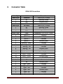
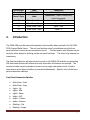
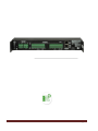
CMSA-100 Manual Cinema Media Server Automation 181 Bonetti Drive San Luis Obispo, CA 93401-7397 USA Phone: +1 805 549 0161 Fax: +1 805 549 0163 www.uslinc.com Table of Contents 1. Safety Notice ......................................................................................................... 3 2. What’s Included .................................................................................................... 4 3. Connector Table .................................................................................................... 5 4. Introduction .......................................................................................................... 6 5. Description and Specifications ............................................................................... 7 6. Installation............................................................................................................ 8 7. Compliance ..........................................................................................................10 8. Product Support ...................................................................................................11 9. Warranty .............................................................................................................11 CMSA-100 Manual v131212 Page 2 1. Safety Notice Review the following safety precautions to avoid injury and prevent damage to this product. To avoid potential risk, use this product only as specified and only for the purpose described in the instruction manual. To Avoid Fire and Personal Injury: Use correct power supply. Use only the power supply provided. Ensure that the AC power outlet is located near the product and is easily accessible. Ground the unit. Connect a safety ground to the ground stud on the rear panel of the CMSA-100. Run a green or green/yellow #14AWG (2.5mm2) wire from the ground stud to the building safety ground (such as grounded metal conduit). Restricted Access. If the CMSA-100 is being used to switch voltages higher than 24V, it must be mounted in an enclosed equipment rack. Circuit Protection. External overcurrent protection is required to protect the CMSA100 relay contacts and the associated wiring. Ensure that power supplied to these contacts is current limited with appropriate fuses, circuit breakers, or current limited power supply. Observe source ratings. To avoid risk of fire or electric shock, the power source must be 100 – 240 VAC, 50 – 60 Hz. Do not operate with suspected failures. If you suspect there is damage or malfunction with this product, call the factory. Do not attempt repair. Only a trained factory service person is authorized to repair this product. Do not operate this product near heat sources. This product should not be located near heat sources such as radiators, heat registers, or stoves. CMSA-100 Manual v131212 Page 3 Provide proper ventilation. The operating temperature range is between 0º C and 40º C. The humidity range is between 20% and 80%, non-condensing. The cooling method is convection. Keep product surfaces clean and dry. Disconnect the power cable from the power source before cleaning. Do not use liquid cleaners or aerosol cleaners. Use a damp cloth for cleaning. Do not push objects into openings of this product. Never insert objects into the product through openings. Do not operate in wet or damp conditions. Do not operate in an explosive atmosphere. Inspect the power cable and all cables prior to use. Confirm that the power cable and other interconnecting cables are free from damage. 2. What’s Included The CMSA-100 Equipment List CMSA-100 automation chassis Mounting ears (2) Pan head screws for mounting ears (8) 12VDC, 1.5A power supply (with international adapters) Connectors for automation wiring (two 12-pin and two 3-pin) 2 meter cat-5 cable for connection to USL CMS-2200 User Manual CMSA-100 Manual v131212 Page 4 3. Connector Table CMSA-100 Connections Left to Right Decca 3-pin 1 2 3 Decca 3-pin 1 2 3 Decca 12-pin 1 2 3 4 5 6 7 8 9 10 11 12 Decca 12-pin 1 2 3 4 5 6 7 8 CMSA-100 Manual v131212 Label PRESHOW NC NO COM OPTION 3 NC NO COM Label Option -2 Option - 2 Option -1 Option -1 Masking - Scope Masking - Scope Masking - Flat Masking - Flat Audio - Feature Audio - Feature Audio - Trailers Audio - Trailers Label NS NS Lights - Down Lights - Down Lights - Mid Lights - Mid Lights - Up Lights - Up Connection 240V AC/DC, 10 Amp Normally Closed Normally Open Common 240V AC/DC, 10 Amp Normally Closed Normally Open Common Connection – 24V AC/DC, 150mA Common Normally Open Common Normally Open Common Normally Open Common Normally Open Common Normally Open Common Normally Open Connection – 24V AC/DC, 150mA Common Normally Open Common Normally Open Common Normally Open Common Normally Open Page 5 4. Left to Right Decca 3-pin Label PRESHOW Decca 12-pin Label 9 10 11 12 Main Show - Stop Main Show - Stop Main Show - Start Main Show - Start Connection 240V AC/DC, 10 Amp Connection – Inputs. Momentary switch to ground. Input - GND Input - 2 Input - GND Input - 1 Introduction The CMSA-100 provides essential automation functionality when used with the USL CMS2200 Cinema Media Server. The unit can function entirely standalone using the front panel switches to exercise each automation circuit. The two power relay outputs may be set to be either pulsed or latching via the rear panel switches. The other relay outputs are momentary. The front panel buttons will exercise each circuit on the CMSA-100 and the corresponding LED above each button will indicate the relay state when the buttons are pressed. The system includes a priority encoder to ensure only a single automation circuit is fired in cases where more than one button is pressed simultaneously. Below is a list of the front panel automation switches Front Panel Automaton Switches Main Show - Start Main Show - Stop Lights - Up Lights - Mid Lights - Down Audio – N/S Audio – Trailers Audio – Feature Masking – Flat Masking – Scope CMSA-100 Manual v131212 Page 6 5. Option – 1 Option – 2 Option – 3 ON Option – 3 OFF Preshow – ON Preshow - OFF System Description Output Relays (Solid State) The CMSA-100 has 10 isolated solid-state relays with momentary outputs. These outputs are rated for 24V AC/DC at 150 mA. Output Relays (Power) The CMSA-100 provides two independent contact relay outputs. They are rated for 240 VAC at 10 A. These relays are configurable to be momentary or latching. Each relay consists of a common, normally open, and normally closed contact. (COM, NO, NC) Inputs There are two inputs on the CMSA-100 designed for contact closure inputs. Interface to CMS-2200 An RJ45 connector with a standard Cat-5 cable is used as the interface to the CMS-2200. This input is NOT Ethernet and will not function if plugged into Ethernet equipment, switches or routers. This interface was specifically designed to be used between the CMSA-100 and the CMS-2200. Power Supply The 12VDC, 1.5A power supply provided with the CMSA-100 comes with multiple adapters for international use. Select the appropriate adapter and install it on the power supply. The power source must be 100 – 240 VAC, 50 – 60 Hz. CMSA-100 Manual v131212 Page 7 Mounting The CMSA-100 comes with two rack-mounting brackets. When attached in forward facing position, they provide a 19-inch standard rack mount solution. They may also be attached in a top or bottom facing position to provide a convenient wall or shelf mounting solution. In all cases, USL recommends mounting the CMSA-100 to provide a stable configuration and clean installation. The four holes found on the rear tabs of the CMSA-100 provide a convenient location for securing automation cables with cable ties. USL recommends carefully routing all automation cables and securing them to provide strain relief and ease maintenance in the future. The CMSA-100 must be mounted in an enclosed equipment rack if it is switching more than 24 volts. Dimensions The CMSA-100 is designed to mount into standard 19” equipment rack and consume 1U of rack space. The overall dimensions are, Height -1.7”, Width - 12.7”, Depth - 4.9” (43mm x 323mm x 124mm). 6. Installation Proper installation of the CMSA-100 is dependent on the functions used and the exact automation configuration that is required. Below is a checklist of installation steps that should apply to all installations. Unpack and confirm that all pieces of the CMSA-100 are present and have no shipping damage. Set the rear panel switches for pulsed or latched relay outputs. The 240V relay contacts (Preshow and Option 3) can be configured for pulsed or latched outputs. If set to latched, separate latch and unlatch buttons and CMS-200 commands are available to latch and unlatch the relay. If set to pulsed, the button or command pulse is passed CMSA-100 Manual v131212 Page 8 through. For example, pressing the Preshow On button would close the normally open contacts as long as the button is held down. The Preshow Off button would have no function. If installing into an equipment rack, install the mounting ears onto the CMSA-100 chassis and mount the unit in the rack. The CMSA-100 must be mounted in an enclosed equipment rack if it is switching more than 24V. Connect a safety ground to the ground stud on the rear panel of the CMSA-100. Run a green or green/yellow #14AWG (2.5mm2) wire from the ground stud to the building safety ground (such as grounded metal conduit). Select the appropriate power adapter for the DC power supply and plug the supply into the CMSA-100 and then to the power source. Confirm that the power LED on the front panel of the unit is on to indicate the unit is powered. Plan the functionality to be used and be sure the correctly rated cables are installed for each automation function to be implemented. External overcurrent protection is required to protect the relay contacts within the CMSA-100 and the associated wiring. Ensure that the wiring connecting to the relay contacts on the CMSA-100 has appropriate fuses, circuit breakers, or current limited power supplies. Properly terminate each automation connection and securely fasten it into the appropriate connector slot. Install the connectors into the CMSA-100 to complete the CMSA-100 automation wiring. Use the front panel switches to selectively test each of the automation functions to be sure they are working correctly. Install a Cat -5 cable between the RJ45 connector labeled “CMS-2200” on the rear of the CMSA-100 and the RJ45 connection labeled “Automation” on the CMS-2200. CMSA-100 Manual v131212 Page 9 The SMS interface for the CMS-2200 can be used to fully exercise the automation system and ensure it is functioning properly. 7. Compliance Certifications Low Voltage Directive 73/23/EEC. EN 60950 Information Technology, Video, and similar Electronic Apparatus. IEC 60950 Safety Requirements. CE, UL, cUL Safety and Overall Compliance. Disposal and Recycling Wheelie-Bin Symbol The Wheelie-Bin symbol is attached to this product in compliance with the EU Directive 2002/96/EC on Waste Electrical and Electronic Equipment (WEEE). Its purpose is to deter the improper disposal of this product and to promote reuse and recycling. Proper Disposal In conformance with the Directive, at end of life this product should be either sent to an appropriate recycling facility for disassembly and recycling or returned to the supplier. Under no circumstances should this product be deposited in a landfill for disposal. Hazards of Noncompliance Electrical and electronic products may contain chemicals, which can leach into the groundwater and cause health concerns through contaminated drinking water. Failure to dispose of this product in compliance with the WEEE Directive may result in penalties as determined by local ordinance. Please contact your dealer or USL, Inc., with questions regarding the proper disposal of this or any other USL product. USL, Inc. contact information: USL, Inc., 181 Bonetti Drive, San Luis Obispo, CA 934017397, USA. Phone: +1 805 549 0161 Fax: +1 805 549 0163 www.uslinc.com CMSA-100 Manual v131212 Page 10 8. Product Support USL proudly stands behind its products. We are ready to answer questions about the installation or operation of the CM-8E. Application notes, manuals, and other documents are available on our website. You may contact us by: Phone: +1 805 549 0161 E-mail: [email protected] You may file a support ticket at: www.uslinc.com/support USL Inc. is interested in your comments. Please feel free to contact us with any comments or suggestions. 9. Warranty One-Year Limited Warranty USL, Inc. warrants that each product manufactured by it will be free from defects in material and workmanship under normal usage for a period of one (1) year after its purchase new from an authorized dealer. Our obligation under this warranty is limited to repairing or replacing any product or component, which we are satisfied, does not conform to the foregoing warranty and which is returned to our factory, freight paid, or serviced by one of our authorized contractors. The foregoing warranty is exclusive and in lieu of all other warranties, whether expressed or implied. Such warranty shall not apply to any product or component (A) repaired or altered by anyone other than USL, Inc. or an authorized service contractor; (B) tampered with or altered in any way or subjected to misuse, negligence or accident or (C) which has been improperly connected installed or adjusted other than in accordance with USL, Inc.’s instruction. CMSA-100 Manual v131212 Page 11 CMSA-100 Manual v131212 Page 12