1
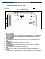
3GS Wireless Node User Guide 3GS Wireless Node 3GS Node QuickWireless Reference Guide User Guide E-LAB-1436 1 E-LAB-1436 3GS Wireless Node User Guide Warning: While this system is an advanced design integrated security system, it does not offer guaranteed protection against burglary, fire or other emergency. Any alarm system, whether commercial or domestic, is subject to compromise or failure to warn for a variety of reasons. Therefore, good installation practices, thorough testing, and regular maintenance by the installation company and frequent testing by the user are essential to ensure continuous satisfactory operation of the system. It is recommended that the installation company offer a maintenance program and instruct the user with the correct procedure for use and testing of the system. COPYRIGHT NOTICE Copyright © 2006 Europlex Technologies Ltd (hereby referred to as Europlex). All rights reserved. No part of this publication may be reproduced, transmitted, stored in a retrieval system, or translated into any language or computer language in any form or by any means electronic, mechanical, magnetic, optical, chemical, manual, or otherwise without the prior written permission of Europlex. Disclaimer: Europlex make no representations or warranties with respect to the contents hereof and specifically disclaim any implied warranties of merchantability or fitness for any particular purpose. Further Europlex reserve the right to revise this publication and to make changes from time to time in the contents hereof without the obligation of Europlex to notify any person of any such revision. All products or services mentioned in this manual are covered by the trademarks, service marks, or product names as designated by the companies who market those products. E-LAB-1436 3GS Wireless Node User Guide, Issue 10, November 2006 Una versión española de este documento está disponible en el CD de información que se incluye con la central SigNET. Une version française de ce document est disponible sur le CD d'information qui est inclus avec la centrale SigNET. Caution All forms of Radio Communications are subject to electromagnetic interference. Signal strength can vary depending on environmental and physical conditions. Any changes to the building structure or equipment within the building may adversely effect signal strength, in these cases the wireless node should be checked to ensure correct operation. It is important that the Installer of the 3GS wireless node takes every precaution to ensure that signal strength is optimised by adhering to the installation recommendations in this user guide. Europlex Technologies [IRL] Ltd. Clonshaugh Business and Technology Park, Clonshaugh, Dublin 17, Ireland. Tel: +353 (0) 1 2500500 Fax: +353 (0) 1 2500592 Europlex Technologies (UK) Limited Innovation Centre, Cranfield University Technology Park, University Way, Cranfield, Bedfordshire, MK43 0BT, United Kingdom. Tel. +44 (0) 8700 600 140 Fax. +44 (0) 8453 307 240 E-Mail: [email protected] Company Web Site address: www.europlex.ie Technical Support: [email protected] 2 E-LAB 1436 3GS Wireless Node User Guide Table of contents 1. 2. 3. 4. 5. Introduction to the 3GS Wireless Node.......................................................... 4 Features ......................................................................................................... 5 Technical Specification .................................................................................. 5 Wiring the Ringnet Interface........................................................................... 6 Wireless Node Programming Interface Overview .......................................... 7 6.1 6.2 6. Supervisory Modes ........................................................................................ 8 7.1 7.2 7.3 7. General Supervisory Mode..................................................................................................................... 8 Enhanced Supervisory Mode ................................................................................................................. 8 To Change Supervisory Modes.............................................................................................................. 8 Enrolling Wireless Devices............................................................................. 9 8.1 8.2 8.3 8.4 8.5 8.6 8.7 8.8 8.9 8.10 8. Key Functions........................................................................................................................................ 7 LED Displays ......................................................................................................................................... 7 To Enrol a Wireless Device (Tamper Enrolment ).................................................................................. 9 To Enrol a Twinned Wireless Device (Tamper Enrolment )................................................................... 9 To Enrol a Wireless Device ( Activation Enrolment ) ........................................................................... 10 To Enrol a Twinned Wireless Device ( Activation Enrolment )............................................................. 10 To Move a Device to a different input .................................................................................................. 10 To Display the Device Status ............................................................................................................... 10 To Set up a Toggle Device................................................................................................................... 10 To Remove a Device............................................................................................................................ 11 To Display the Sensor Signal Strength ................................................................................................ 11 To Display the Background interference level...................................................................................... 11 Wireless Node 7-segment LED displays during normal operation............... 12 Appendix-1 Enrolling the MCT-303 Shock Sensor..........................................................................13 Appendix-2 Wireless Node Enclosure.............................................................................................14 Appendix-3 Installing the 3GS Wireless Node ................................................................................15 E-LAB 1436 3 3GS Wireless Node User Guide 1. Introduction to the 3GS Wireless Node The 3GS Wireless Node provides an interface for multiple 868 MHz wireless detectors. The node should be powered up for at least 30 seconds before performing any operations. This node does not support IR communication. Fig 1. 3GS Wireless Node 2 3 4 6 5 1 8 7 10 9 1. Ringnet Interface This is the 3GS communications bus used to network Nodes together on the 3GS system. (See 4 – Wiring the RINGNET interface) 2. Auxiliary Jumper [JP5] This jumper must be fitted, linking the two pins together for correct operation of the wireless Node on the 3GS. (See Note below) 3. Tamper By-pass [JP2] This jumper setting determines the operation of the tamper. The tamper operation can be overridden by fitting JP2. The engineer must ensure that JP2 is removed before leaving site for the system to comply with standards. 4. Front Tamper Switch The wireless Node uses a front tamper switch with spring. When the lid is closed the spring closes the switch. 5. Production Test This interface is used for production test purposes only. Do NOT use. 6. Diversity Antenna The diversity antenna extend the range of signal detection. Prevent contact with wires. Do not Bend. 7. Ringnet status LED This LED Indicates the status of the Ringnet communications bus. 8. Buzzer The Buzzer is used to provide audio confirmation of programming and assist in to locating the node. 9. Aux Out An Auxiliary Output of 12V DC is provided to power additional external devices to a maximum of 200 mA. 10. DC IN The Power input for the Node is 12V DC 4 E-LAB-1436 3GS Wireless Node User Guide Please ensure that jumper JP5 is fitted for correct operation of the wireless Node. Failure to do so will result in unstable operation of the 3GS system. Note 2. Features The following features have been incorporated into the design of the 3GS wireless Node. • • • • • • • • • 3. Inputs – multiple wireless device inputs using 868 MHz wireless detectors Easy device enrolment ( Tamper and activation) using the built in 7-segment display and 3 button keypad. Supports tamper or activation enrolment allowing you to choose the most convenient method for a given detector. Supports 2 Supervisory modes ( Selectable at power-up) Display shows status and properties of enrolled devices for instant feedback. Front Tamper – Spring with configurable tamper bypass option. Sensor Signal strength indication – LED indication ( 0-9) of the signal strength of an enrolled device. Background Signal strength indication – LED indication ( 0-9) of the background noise signal strength. Supervisory Signal detection – LED indication ( A ) of a missed supervisory signal from enrolled sensor. Technical Specification Table 1 below details the technical specifications for the 3GS Wireless Node. Table. 1 Technical Item Specification Security Grade EN50131-1; 1997 Grade 2 PD6662:2004 Grade 2 Class II Indoor General 150 x 82 x 20 mm 200 x 153 x 47 mm 13.7 VDC 9.5 VDC 60 mA 50 mA Multiple wireless 868 MHz Detectors Indicates Ringnet communications status Front Spring Tamper -10 C to +40 C 0% to 90% (non-condensing) Ringnet - RS485 at 307K2 baud Flash General Supervisory Mode (Default) 12 Hr Enhanced Supervisory Mode 2Hr Environmental Class PCB Dimensions Enclosure Dimensions Operating Voltage Minimum Operating Voltage Maximum Operating Current Quiescent Current Inputs Status LED Tamper Temperature Range Humidity Range Communications Memory Backup 2 Supervisory Modes E-LAB-1436 5 3GS Wireless Node User Guide 4. Wiring the Ringnet Interface Fig. 2 1A 1B 2A 2B The Ringnet interface provides for the networking of nodes to the 3GS system. It uses RS458 in a ring topology providing a maximum distance between nodes of 1000 meters using Belden 9829 cable. Table 2 shows the maximum distances for other cable types. From Previous Node Cable type Distance between nodes Belden 9502 (screened) 200m UTP Category: 5 (solid core) 400m Belden 9829 400m Branch Node Table. 2 Wireless node 1A 1B 2A 2B SHLD 3A 3B 4A 4B 1A 1B 2A 2B The Ringnet interface baud rate is 307kb. The wiring of the Ringnet interface on the wireless node is shown in Fig.2. The 8 terminals 1A 1B to 4A 4B provide for the connection of an additional branch node if required. To Next Node 2A 2B 1A 1B If the branch node is not connected then the 4 terminals 1A 1B 2A 2B are used to connect to the Ringnet cable. 6 E-LAB 1436 3GS Wireless Node User Guide 5. Wireless Node Programming Interface Overview The Wireless Node Programming Interface consists of the following: 1. Two 7 segment LED displays ( Left & Right) that indicate the input number and the state / properties of each of the eight possible devices. 2. 3 keys for selecting and programming each device. [ Next, Select & Escape ] Fig 3. Wireless Node programming interface Left LED Right LED Next Select [ SEL ] Escape [ ESC ] Device Status/Properties Input Number 6.1 Key Functions The function of each of the 3 keys is listed below: Select [SEL] Key: This key is used to select the required display function. The user can circulate through each of the available display functions by repeatedly pressing this key. Next Key: This key is used to circulate through each of the eight possible devices for the selected display function. Note: not all of the display functions will have device dependant properties, in these cases the Next key will have no function. Escape [ESC]: This key is used to exit the current function and return to the normal operating state. 6.2 LED Displays In the normal operating state, the two LED’s of the programming interface will be blank. The Left LED of the programming interface is used to display the wireless input number associated with a particular display function ( 8 inputs in total). This LED is also used to indicate that the background signal strength is being monitored as listed below: Left 7 segment LED Output Description Display 1 2 3 4 5 6 7 8 F E-LAB-1436 Description Wireless Input 1 Wireless Input 2 Wireless Input 3 Wireless Input 4 Wireless Input 5 Wireless Input 6 Wireless Input 7 Wireless Input 8 Background Interference Signal Strength 7 3GS Wireless Node User Guide The Right LED of the wireless node programming interface is used to display the Device status. Each of the seven segments corresponds to a particular state or condition as shown below. The Horizontal segments indicate Device Properties while the vertical segments indicate Device states. Fig.4 Right 7 segment LED Output Display Enrolled Tamp er Enrolled (A) Low Battery Tamper Enrolled ( B) Ope n Open Off-Line Toggle 6. Supervisory Modes The 3GS wireless node supports 2 types of supervisory modes – General and Enhanced. The supervisory mode of the node is flashed three times on the two LED’s at power up as follows: - 0 for General Supervisory mode - 1 for Enhanced Supervisory mode 7.1 General Supervisory Mode In this mode of supervision the 3GS wireless node will monitor all enrolled wireless sensors for a supervisory signal over a 12 hour period. If no supervisory signal is received from any of the enrolled sensors within that period, the node will indicate that the sensor is lost by displaying “L” on the left 7segment display with the corresponding sensor input displayed on the right LED. The wireless node will then report the input as a “Short” to the 3GS controller. This supervisory mode is the default mode. 7.2 Enhanced Supervisory Mode In this mode of supervision the 3GS wireless node will monitor all enrolled wireless sensors for a supervisory signal over a 20 minute period. If no supervisory signal is received from any of the enrolled sensors within that period, the node will indicate an advisory signal (“A”) on the left 7-segment display with the corresponding sensor input displayed on the right LED. If after 2 hours the device has not communicated with the node, then a lost signal “L” will be displayed on the 7-segment display and the input will be reported as a “Short” to the 3GS controller. 7.3 To Change Supervisory Modes To change supervisory modes on the 3GS wireless node, - Remove power from the node - hold down the Select [SEL] Key and power up the node - Release key when the 7-segment display starts flashing A number representing the supervisory mode will be flashed three times on the right 7-segment LED. ( 0 for General mode, 1 for Enhanced mode). To revert back to the previous supervisory mode simply repeat the procedure. 8 E-LAB 1436 3GS Wireless Node User Guide Supervision applies only to supervised sensors. Not all sensors are supervised. Please consult the installation leaflet accompanying the wireless sensor to determine if the sensor is supervised or not. Note 7. Enrolling Wireless Devices The 3GS wireless node provides 2 methods of enrolling a wireless sensor. • • Tamper Enrolment Activation Enrolment When enrolling a wireless device on the 3GS wireless node it is important to remember the following points: 1) Wireless sensors successfully enrolled when in close proximity to the node must be checked for signal strength when placed in their final location. (See 8.9 To Display the Sensor Signal Strength) 2) If signal strength is less than 2 you will not be able to enrol the detector. Please consider re-positioning the wireless node or detector or adding an additional wireless node. Europlex recommends that the value of the signal strength of the enrolled device be 4 or above to ensure reliable operation. 3) Europlex recommend that the sensor be located at a minimum distance of 3 meters from the 3GS wireless node during enrolment. 4) Perform a background interference test at the beginning and end of the installation to ensure a value of 0 ( See 8.10 To Display the Background interference level.) 8.1 To Enrol a Wireless Device (Tamper Enrolment ) To enrol a device using tamper enrolment the user must simply do the following from the normal operating state: 1. Press the Select [SEL] key and then release to enter monitor mode. 2. Press NEXT to select the required input number ( Displayed on Left LED ) 3. Hold Select [SEL] until the TAMPER segment flashes and the node starts to beep ( indicating the wireless node is in tamper enrolment mode) 4. Trip the tamper on the required detector ( Wait for the LED on the sensor to go out ), repeat until the wireless node indicates successful enrolment by giving a long beep and returning to monitor mode. 5. Note that the ENROLLED (A) segment for this input is now on. 6. Verify correct enrolment by tripping the detector and checking that the OPEN segment comes on. 7. Press escape to commit enrolment to FLASH memory. 8.2 To Enrol a Twinned Wireless Device (Tamper Enrolment ) A second (or twinned) wireless device can be enrolled on the same input allowing the wireless node to accommodate up to 16 wireless sensors. To enrol a twinned device using tamper enrolment the user must simply do the following from the normal operating state: 1. Press the Select [SEL] key and then release to enter monitor mode. 2. Press NEXT to select the required input number ( Displayed on Left LED ) 3. Hold Select [SEL] until the TAMPER segment flashes and the node starts to beep ( indicating the wireless node is in tamper enrolment mode) 4. Trip the tamper on the required detector ( Wait for the LED on the sensor to go out ), repeat until the wireless node indicates successful enrolment by giving a long beep and returning to monitor mode. 5. Note that the ENROLLED (B) segment for this input is now on. 6. Verify correct enrolment by tripping the detector and checking that the OPEN segment comes on. 7. Press escape to commit enrolment to FLASH memory. Note E-LAB-1436 If an attempt is made to enrol a third device on a single input, the 7 segment LEDs will display the characters " E r " and the node will beep quickly to indicate an error. 9 3GS Wireless Node User Guide 8.3 To Enrol a Wireless Device ( Activation Enrolment ) Some detectors do not have tamper detection capability, to enrol these detectors you must use Activation enrolment. To enrol a device using activation enrolment the user must simply do the following : 1. 2. 3. 4. 5. 6. 7. 8.4 Press the Select [SEL] key and then release to enter monitor mode. Press NEXT to select the required input number ( Displayed on Left LED ) Hold the Select [SEL] Key until the flashing segment changes to the OPEN segment (indicating that the wireless node is in activation enrolment mode) Trip the required detector (wait for the LED on the sensor to go out), repeat until the wireless node indicates successful enrolment by giving a long beep and returning to monitor mode. Note that the ENROLLED (A) segment for this input is now on. Verify correct enrolment by tripping the detector and checking that the OPEN segment comes on. Press escape to commit enrolment to FLASH memory. To Enrol a Twinned Wireless Device ( Activation Enrolment ) To enrol a second or twinned device using activation enrolment the user must simply do the following : 1. 2. 3. 4. 5. 6. 7. 8.5 Press the Select [SEL] key and then release to enter monitor mode. Press NEXT to select the required input number ( Displayed on Left LED ) Hold the Select [SEL] Key until the flashing segment changes to the OPEN segment (indicating that the wireless node is in activation enrolment mode) Trip the required detector (wait for the LED on the sensor to go out), repeat until the wireless node indicates successful enrolment by giving a long beep and returning to monitor mode. Note that the ENROLLED (B) segment for this input is now on. Verify correct enrolment by tripping the detector and checking that the OPEN segment comes on. Press escape to commit enrolment to FLASH memory. To Move a Device to a different input Any enrolled wireless sensor can be switched to a different input. To move the sensor simply repeat the enrolment process (Activation or Tamper) for that sensor using a different input number. The 3GS wireless node will automatically remove the sensor from the previous input. When moving a twinned device to a different input, both devices will be removed from the original input. Therefore each device must be separately enrolled to their respective inputs. Note 8.6 To Display the Device Status To display the status of a device from the normal operating state the user must do the following: 1. Press the Select [SEL] key to enter monitor mode. 2. Press NEXT to select the required input number ( Displayed on Left LED ) 3. The status of the selected input device will be displayed on the right LED in accordance with the display properties shown in fig. 3. 8.7 To Set up a Toggle Device A toggle device changes state for each activation of the wireless detector. Only non-supervised sensors should be enrolled as toggle devices. To set up a toggle device the user must do the following: 1. 2. 3. 10 Enter the required enrolment Mode as described above [ Tamper or Activation] Press the NEXT key, the toggle segment of the display will come on. Enrol Device as before. E-LAB 1436 3GS Wireless Node User Guide 8.8 1. 2. 3. To Remove a Device In monitor mode select the input that you wish to remove. Enter enrolment mode ( Hold the SEL key until TAMPER segment flashes) Press the ESC key When removing a twinned device, both devices will be removed at the same time. If one of the twinned devices is required to remain on that input, then it must be enrolled again. Note 8.9 To Display the Sensor Signal Strength The 3GS Wireless node provides information on the signal strength of the wireless signal from the sensor to the wireless node. To display this information from the normal operating state the user must do the following: 1. 2. 3. 4. Press the Select [SEL] Key twice. The Left LED will display the Input number and the signal strength for that input will be flashed on the right LED as a value from 0 (Min) to 9 (Max) . To view the signal strength of the next input simply press the Next [NXT] Key. To return to the normal operating condition press the Escape [ESC] Key. 8.10 To Display the Background interference level. The 3GS wireless node also provides a measure of the background electromagnetic interference in the frequency band (868/869 MHz). To display this information from the normal operating state the user must do the following: 1. 2. 3. 4. Note E-LAB-1436 Press the Select [SEL] Key three times. The Left LED will display the letter “F” The right LED will display a value from 1 (Min) to 8 (Max) to indicate the background interference level. To return to the normal operating condition press the Escape [ESC] Key. The value displayed on the right LED is a measure of the average electromagnetic interference that was recorded in the frequency band (868/869 MHz) over a given time period. If a non zero value is displayed, it is recommended that the Wireless node be positioned in a different location which yields a background interference level of 0. If a level of 0 cannot be obtained please contact Europlex for advice. 11 3GS Wireless Node User Guide 8. Wireless Node 7-segment LED displays during normal operation. During normal operation of the wireless node, the 7 segment display LED’s will provide visual indicators if certain events occur. These indicators will aid the installer in the maintenance, debug and operation of the wireless node. Indication of Jamming Frequency Detection. If a Jamming signal is detected in the sensor frequency range ( 868MHz or 869MHz ), the 7 segment LEDs will present the characters "Jd" as shown. This is reported to the 3GS controller as a node Jamming detect event. Indication of tamper detection If a tamper is detected on any of the input devices, the left LED will indicate the tamper condition with the character " t " and the right LED will indicate the wireless input number of the tamper. This display will flash and the node will beep every minute until the tamper is reset. If a tamper of the wireless node itself is detected the display will indicate “t 0”. (e.g. the LEDs shown indicate a tamper condition detected on device 3) This is reported to the 3GS controller as a zone tamper (discon) event. Indication of Low Battery Detection If a low battery condition is detected in any of the devices, the left LED will indicate the low battery condition with the character " b " and the right LED will indicate the wireless device number where the low battery condition was detected. (e.g. the LED’s shown indicate a low battery condition detected on device 3) This is reported to the 3GS controller as a node battery problem. Indication of Lost or off-line device If a lost or off-line condition is detected in any of the devices, the left LED will indicate this condition with the character " L " and the right LED will indicate the wireless device number where the lost condition was detected. (e.g. the LED’s shown opposite indicate a lost sensor condition detected on device 3) This is reported to the 3GS controller as a zone short event. Supervisory fault condition on Input When a supervisory signal from an enrolled wireless sensor has not been detected within the required period. This condition will only be displayed for the Enhanced Supervisory mode. ( e.g. the LED display shown indicates a supervisory fault condition on input 1.) This is reported to the 3GS controller as a supervision advisory event. Error when attempting to enrol a third device on an input If an attempt is made to enrol a third device on a single input, the 7 segment LEDs will display the characters " Er " and the node will beep quickly to indicate an error. This is not reported to the 3GS controller. 12 E-LAB 1436 3GS Wireless Node User Guide Appendix-1 Enrolling the MCT-303 Shock Sensor The 3GS wireless node supports a complete range of sensors such as PIR’s, contact sensors, shock sensors, etc…For a complete list please contact Europlex. Battery connector Fixing hole Tamper switch “Top” Fixing hole Battery Impact sensor LED lamp Mode jumper Cover screw Wireless transmitter Reed switch The MCT-303 is a single or dual zone wireless sensor designed to provide perimeter protection without the need for expensive and time-consuming cabling. The unit has two modes, a shock sensor digitally detects impacts made to the mounting surface whilst a reed switch can be used to monitor opening sections of doors and windows. Dual Mode Desensitise Calibrate For the correct operation of the MCT-303 shock sensor with the 3GS wireless node, please ensure that the sensor is configured for Dual mode operation ( Top Link ON ) Before enrolling the MCT-303 Shock Sensor onto the 3GS Wireless Node please ensure that the sensor is calibrated as detailed below: Calibrating the MCT-303 Shock Sensor Place the jumper link onto the calibrate pins (shown in the diagram above). Press the tamper switch once and release. Expose the MCT-303 sensor to a sample of background vibration. This vibration may consist of tapping the window with the butt of a screwdriver or operating loud machinery near the sensor. Press the tamper switch again to complete the calibration process. Remove the Jumper link from the Calibrate pins. Additional information on calibrating the MCT-303 sensor is available from the sensor installation leaflet. E-LAB-1436 13 3GS Wireless Node User Guide Appendix-2 Wireless Node Enclosure The wireless node enclosure specifications are included below. The enclosure material is composed of an ABS resin with a flammability rating to UL94HB. 1. 2. 3. 4. 5. 6. 7. 8. Node anchor points Wall spacers Cover anchor points Cable grips Mounting holes Cable entry holes Cable ties Cover hooks 1. Front tamper guide 2. Cover fixing screws 3. Infrared window 14 E-LAB-1436 3GS Wireless Node User Guide Appendix-3 Installing the 3GS Wireless Node When installing the 3GS wireless node it is important to minimise any electromagnetic interference from the environment in which the node is installed. Always adhere to the following guidelines for good installation practice: • • • Ensure that the node is at a minimum of 1 meter away from mains power lines. Ensure that the node is at a minimum of 1 meter away from metal cabinets or any other large metallic objects. Ensure that the node is at a minimum of 1 meter away from any sources of electromagnetic radiation. Europlex recommend that the wireless sensor be located at a minimum distance of 3 meters from the 3GS wireless node. Note E-LAB-1436 15