1
MODEL 6745
BABY SCALE
Operation Manual
8535-M074-O1 Rev A
04/05
CARDINAL SCALE MFG. CO.
PO BOX 151 v WEBB CITY, MO 64870
PH (417) 673-4631 v FAX (417) 673-5001
www.detectoscale.com
1
Printed in USA
2
TABLE OF CONTENTS
INTRODUCTION
QUICK START
INSTALLATION
Unpacking
Level Adjustment
Baby Tray Installation
Battery installation
Low Battery Indicator
Battery Status
Battery Charging
Placing the Scale
KEYPAD FUNCTIONS
ANNUNCIATORS
OPERATION
Basic Weighing operation
Operating Hints
CARE AND CLEANING
PRINTER OUTPUT
SERIAL DATA FORMATS
SETUP AND CALIBRATION
SETUP REVIEW
ERROR AND STATUS DISPLAYS
BEFORE YOU CALL SERVICE
PART IDENTIFICATION
"
1
1
2
2
2
3
4
5
5
5
5
6
7
8
8
8
8
9
9
10
16
17
17
18
SERIAL NUMBER _____________________
DATE OF PURCHASE _________________
PURCHASED FROM __________________
____________________________________
____________________________________
RETAIN THIS INFORMATION FOR FUTURE USE
PRECAUTIONS
Before using this instrument, read this manual and pay special attention to
all "WARNING" symbols:
IMPORTANT
ELECTRICAL
WARNING
3
STATIC
SENSITVE
4
INTRODUCTION
The Model 6745 Baby Scale is a 30 pound (15 kilogram) capacity, battery-operated baby scale
housed in a painted steel enclosure. The scale is equipped with a removable baby tray and a
color coded membrane keyboard. The Model 6745 has a number of special features that
make it both easy to use and maintain. This manual contains information on the operation of
the scale. Please take time to read the manual before using your new Model 6745.
FCC COMPLIANCE STATEMENT
WARNING! This equipment generates uses and can radiate radio frequency and if not
installed and used in accordance with the instruction manual, may cause interference to radio
communications. It has been tested and found to comply with the limits for a Class A
computing device pursuant to Subpart J of Part 15 of FCC rules, which are designed to provide
reasonable protection against such interference when operated in a commercial environment.
Operation of this equipment in a residential area may cause interference in which case the
user will be responsible to take whatever measures necessary to correct the interference.
You may find the booklet “How to Identify and Resolve Radio TV Interference Problems”
prepared by the Federal Communications Commission helpful. It is available from the U.S.
Government Printing Office, Washington, D.C. 20402, stock No. 001-000-00315-4.
All rights reserved. Reproduction or use, without expressed written permission, of editorial or pictorial
content, in any manner, is prohibited. No patent liability is assumed with respect to the use of the
information contained herein. While every precaution has been taken in the preparation of this manual,
the Seller assumes no responsibility for errors or omissions. Neither is any liability assumed for
damages resulting from use of the information contained herein. All instructions and diagrams have
been checked for accuracy and ease of application; however, success and safety in working with tools
depend to a great extent upon the individual accuracy, skill and caution. For this reason the Seller is
not able to guarantee the result of any procedure contained herein. Nor can they assume responsibility
for any damage to property or injury to persons occasioned from the procedures. Persons engaging
the procedures do so entirely at their own risk.
QUICK START
Although it is recommended that you read this manual before attempting to operate the scale,
this section is included to provide a condensed set of instructions on installing and using the
scale. At a minimum, please make certain you read all of the caution and warning statements.
Step 1 Install the baby tray by sliding the baby tray onto the weighbridge. Make sure the
release knob “clicks” and locks the tray in place.
Step 2 Turn the scale over on the tray, locate and remove the battery access cover on the
bottom of the scale. Install six (6) “C” size batteries and then replace the cover.
Step 3 Turn the scale over to the normal operating position.
Step 4 Press the ON key to turn the scale on. If desired, place a blanket or pad on the
baby tray and press the ZERO key to reset the weight display to zero.
Step 5 Place the baby on the scale. Wait a few seconds for the weight to display and then
read the baby’s weight. Press the UNITS key to toggle between Pounds & Ounces
and Kilograms weighing units.
Step 6 Remove the baby from the scale. Press the OFF key to turn the scale off.
1
INSTALLATION
Unpacking
Begin the installation by removing your new Model 6745 Baby Scale from the shipping carton.
Examine the scale and baby tray for any damage that may have taken place during shipment.
If you find evidence of shipping damage, the shipping company should be contacted at once.
It is a good idea to keep the scale shipping carton and packing material for later use should
storage or transport of the scale become necessary.
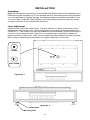
Level Adjustment
Check to make certain the scale is level. The level indicator is located in the center of the
weighbridge under the baby tray. Remove the baby tray and observe the level bubble (see
Figure No. 1). If the scale is not level (the bubble will not be centered), loosen the locking nut
on all four (4) mounting feet (see Figure No. 2) and adjust them as required to center the
bubble and attain a level scale. Once a level condition has been obtained, lock the mounting
feet in place by tightening the adjustment nuts against the bottom of the scale.
Leveled
Not Leveled
Figure No. 1
Figure No. 2
Locking Nut
Mounting Foot
2
INSTALLATION, Cont.
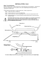
Baby Tray Installation
Before using the scale, it will be necessary to install the baby tray and batteries. Note that the
baby tray is designed to lock into place on the scale weighbridge preventing accidental
separation from the scale.
Follow the steps listed below to install the baby tray. Refer to figure No. 3.
Step 1 Place the scale on a table top.
Step 2 Position the baby tray onto the weighbridge.
Step 3 Slide the baby tray onto the weighbridge until you hear the release knob “click”.
Step 4 Verify the baby tray is locked in place by making certain that it cannot be slide to
the left or right.
CAUTION! Make absolutely certain that the baby tray is locked in place before
using the scale. Be sure that the locking knob is in the locked position.
Failure to lock the baby tray in place can result in injury to the baby should
the tray separate from the scale.
Figure No. 3
Baby Tray
Measuring Tape
Release Knob
Level Bubble
Weighbridge
Release Knob in
Locked Position
Pull Out
To remove baby tray from scale, pull Release Knob and slide tray off weighbridge.
3
INSTALLATION, Cont.
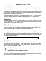
Battery Installation
The 6745 Baby Scale can use 6 "C" size Alkaline, Ni-Cad or NiMH batteries (not included). If
you wish to operate the scale from batteries, you must first obtain and install batteries before
operations can begin. The batteries are contained in a battery holder inside the scale. Access
is via a removable panel on the bottom of the scale.
The scale can operate for 200 hours of continuous use when using Alkaline batteries or with
fully charged Ni-Cad or NiMH batteries, 50 hours of continuous use.
NOTE! When using Alkaline batteries, make sure the QL&$G setup option is disabled (set to 0).
Refer to Setup and Calibration or Setup Review.
Use the following procedure to install the batteries.
Step 1 With the baby tray installed, turn the scale upside down on a stable surface.
Step 2 Locate the rectangular panel on the bottom of the scale and remove the thumb
screw retaining it.
Step 3 Remove the panel (lift straight up and slide it out) exposing the battery holder.
Step 4 Install 6 "C" size batteries in the holder, making certain they are positioned in
accordance with the polarity markings located in the battery holder. Refer to Figure
No. 4.
Step 5 After placing all 6 batteries in the battery holder, replace the panel on the bottom of
the scale (slide the tab in the slot on the scale) and install the thumb screw.
+
-
-
+
Figure No. 4
Step 6 Turn the scale over and press the ON key.
Step 7 If the display turns on, the batteries have been installed correctly. If not, turn the
scale over, remove the panel and check for one or more improperly positioned
batteries.
The 6745 Baby Scale can be operated from a power supply or from Alkaline,
Ni-Cad or NiMH batteries. All six (6) batteries must be of the same type. They
must all be Alkaline, all Ni-Cad or all NiMH. DO NOT mix Alkaline and Ni-Cad or
NiMH batteries. The power supply is also used to recharge the batteries, when
the scale is operated from Ni-Cad or NiMH batteries. DO NOT connect a power
supply to the scale if using Alkaline batteries.
4
INSTALLATION, Cont.
Low Battery Indicator
When the batteries are near the point they need to be replaced (Alkalines) or recharged
(NiCad or NiMH), the low battery annunciator on the display will turn on (see Figure No. 5) If
the battery voltage drops too low for accurate weighing, the scale will automatically shut off
and you will be unable to turn it back on.
If using Alkaline batteries when the low battery annunciator turns on, turn the scale off, remove
the old batteries and replace with new ones. Follow the same procedure for installing batteries
when battery replacement becomes necessary.
If using NiCad or NiMH (and the QL&$G setup option is enabled, set to 1 or 2), plug the power
supply into the scale and then into the proper electrical wall outlet. The scale will begin
charging the batteries.
Battery Status
If batteries are used, the scale will show the battery status on power up. The display will show
E$WWU\ then change to ò << ò, where YY indicates the remaining battery voltage expressed
as a percentage (%) of the total battery voltage.
Battery Charging
To recharge the Ni-Cad or NiMH batteries, the power supply must be connected to a AC power
outlet and plugged into the scale. It will take approximately 15 hours to fully recharge the
batteries in the scale. While the batteries are charging the scale can still be operated. Note
that charging the batteries for more than 15 hours will not damage them.
When the scale is to be turned off, pressing the OFF key once will display “dashes" scrolling
across the display indicating the batteries are being charged. Pressing the OFF key again, will
display 2)) and turn the scale off. If the power supply is disconnected before the 15 hours,
the scale will continue to charge the batteries when the power supply is plugged back in. Note
that the auto-shutdown feature (if enabled during setup and calibration) will be disabled when
the scale is charging the batteries.
NOTE! When the scale is turned off, it is NOT charging the batteries.
Placing the Scale
After the batteries have been installed, the scale may be prepared for use. Place the scale on
a stable, vibration-free level surface away from direct sunlight and from any rapidly moving air
source (heating/cooling vents, fans, etc.). Make certain the power cord and peripheral cables
are routed out of the way of normal traffic. If the scale is unstable, adjust the front legs up or
down as necessary until the scale is stable.
CAUTION! Make certain that the structure beneath the scale is of sufficient
strength to hold both the scale AND the maximum load to be placed on the
scale. Failure of the supporting structure can result in an injury to the baby in
the baby tray, as well as damage to the scale.
Installation of the scale is now complete. Please read the operating instructions contained in
this manual before attempting to operate your scale.
5
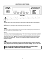
KEYPAD FUNCTIONS
Figure No. 5
The membrane keypad is not to be operated with pointed objects (pencils,
pens, fingernails, etc). Damage to keypad resulting from this practice is NOT
covered under warranty.
ON I
With the indicator off, pressing this key will apply power to the scale and turn on the display.
OFF {
If the scale is on, pressing this key will remove power from the scale.
Î|Í
ZERO
This key is used to reset the display to zero up to the limit set during setup and calibration of
the scale. (See Setup and Calibration, USA)
UNITS
This key is used to change the weighing units to the alternate units of measurement if selected
during setup of the scale (WEIGHTING UNITS = 2 or 3). For example, with pounds displayed
(lb annunciator turned on) pressing this key will change the weighting units to kilograms (kg
annunciator will turn on). NOTE! This feature must be enabled during setup and calibration
for this key to be operational. This key is also used during setup and calibration to toggle
between the values.
~
PRINT
If an optional printer is connected to the scale, and the weight display is locked on the baby’s
weight, pressing this key will send the weight data to the printer. NOTE! This key is also used
during setup and calibration to display and then save the current setting.
NOTE! The scale will not respond to pressing the PRINT key unless the weight
display is stable and the Weight Lock annunciator is turned on.
6
ANNUNCIATORS
The annunciators are turned on to indicate that the display is in the mode corresponding to the
annunciator label or that the status indicated by the label is active.
Î0Í (Center-of-Zero)
The Center-of-Zero annunciator is located to the lower right of the ounce weight display and is
turned on to indicate that the weight is within +/- 1/4 division of the center of zero.
[\ (Stable)
The (Stable) annunciator is located to the far lower right of the ounce weight display and is
turned on when the weight display is stable. When off, it means that the change in successive
weight samples is greater than the motion limits selected during setup and calibration.
POUND
The POUND annunciator is located on the left of the weight display and is turned on when the
pounds & ounces mode is selected to show that the displayed weight is pounds.
OUNCE
The OUNCE annunciator is located slightly to the right center of the weight display and is
turned on when the pounds & ounces mode is selected to show that the displayed weight is
ounces.
kg
The kg annunciator is located on the right of the weight display and is used to indicate that the
displayed units of weight measurement is kilograms.
b
LOW BATTERY
The low battery annunciator is used with the battery operation. It will turn ON to indicate that
the batteries will soon need to be replaced (if using Alkaline) or recharged (if using NiCad or
NiMH). No change in operation will occur until just before the battery voltage drops to a level
where operation is affected. At this level, the indicator will automatically turn itself off.
WEIGHT LOCK
The WEIGHT LOCK annunciator is turned on to show that the scale is locked onto the weight.
7
OPERATION
The following steps describe the operation of the Model 6745 Baby Scale. Note that a set of
condensed instructions appear on the face of the scale as well.
Basic Weighing Operation
Step 1 Press the ON key. The scale display will turn on showing the model number,
battery status and if the threshold feature is enabled, the last locked weight will
display. Press the UNITS key to select the desired weighing unit. Note that
pressing the UNITS key causes the scale to alternate between pounds & ounces
and kilograms. Annunciators will turn on to indicate which weighing units have
been selected.
Step 2 If desired, a blanket or similar covering may be placed in the baby tray at this time.
Make certain that the blanket does not extend over the tray and touch surrounding
objects (including the scale enclosure) or the weight reading could be incorrect.
Press the ZERO key and make certain that the display shows a zero weight
reading.
Step 3 Place the baby in the baby tray and observe the scale display. If the threshold
feature was enabled during setup and calibration, in a few seconds the Weight
Lock annunciator will turn on, signaling that the weight display is locked and the
baby may be removed from the scale. Note, that if a printer is attached to the
scale, the weight data will automatically print.
Step 4 Remove the baby from the scale.
Step 5 Record the baby’s weight from the weight display. Note that after a short period of
non-use the scale will turn off. To resume operation, press the ON key.
OPERATING HINTS
A. Remember that all items (blankets, pads, toys, etc.) that are not to be included in the
weight should be placed on the baby tray and the ZERO key pressed. This will insure
that the item(s) will not be included in the child’s weight.
B. If the child is very active it may take a few seconds longer for the Weight Lock
annunciator to turn on. During this time the scale’s is busy calculating the weight.
C. If the scale is not in use, press the OFF key to conserve battery life. Note that if the
Sleep Mode was activated during setup and calibration, the scale will turn off
automatically after the time set for the sleep mode.
CARE AND CLEANING
1. DO NOT submerge the scale in water, pour or spray water directly on it.
2. DO NOT use acetone, thinner or other volatile solvents for cleaning.
3. DO NOT expose the scale to temperature extremes.
4. DO NOT place the scale in front of heating/cooling vents.
5. DO clean the scale with a damp soft cloth and mild non-abrasive detergent.
6. DO remove power before cleaning with a damp cloth.
7. DO provide clean AC power and adequate protection against lightning damage.
8. DO keep the surroundings clear to provide clean and adequate air circulation.
8
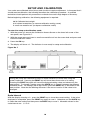
PRINTER OUTPUT
The Model 6745 Baby Scale has a RS-232 serial port that may be connected to an optional
printer to record weight. The output connector is located on the rear panel (see Figure No. 6).
When the weight display is locked on the baby’s weight and the Weight Lock annunciator is
turned on, the weight data may be transmitted by pressing the PRINT key or on demand with
receipt of a command from a computer). NOTE! If the threshold feature was enabled during
setup and calibration, with a printer attached to the scale, the weight data will automatically
print when the weight display locks on the baby’s weight.
PIN NO.
2
3
5
FUNCTION
DATA INPUT (RXD)
DATA OUTPUT (TXD)
SIGNAL GROUND (GND)
1
6
9
5
Figure No. 6
The serial port can be configured during the setup and calibration procedure or during the
setup review operation. Using either method, it is possible to select the baud rate, data format
and print ticket format. NOTE! The scale is shipped with the baud rate set to 9600 baud.
SERIAL DATA FORMATS
If the scale is connected to a computer, it will transmit a single set of weight data each time the
computer sends an ENQ (hex 05) or a SMA weight request (W). Examples and explanation of
the data format transmitted are shown below.
The host device (computer) sends:
ENQ (hex 05) or <lf> W <cr>.
The scale will respond with:
<lf><s><r><n><m><xxxxxxxxxx><uuu><cr>.
Where:
lf =
s=
Line Feed
Flags
r=
n=
m=
xxxxx:xx.x =
xxxxxx.xxx =
Range
Mode
Motion
Weight
uuu =
cr =
Units
Carriage Return
Z= center of Zero
O = Over cap
E = zeroError,
e = weight not currently being displayed
1, 2, 3, ...
G = Gross
M = Motion, " "(blank) = no motion
Ten digits (includes decimal point), lb/oz mode
Ten digits (includes decimal point), kg mode
Weight is right justified.
l/O^ (lb & oz), kg^ (kilograms), (^ = space)
(hex 0D)
9
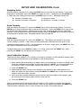
SETUP AND CALIBRATION
Your scale was calibrated at the factory and should not require adjustment. In the event that it
should need recalibration, the following describes the calibration procedure. A qualified
technician should perform this procedure to maintain the scale’s high degree of accuracy.
Before beginning calibration, the following equipment is required:
30 lb Calibrated test weight
3/16 slotted screwdriver (to remove calibration sealing screw)
A small non-metallic tool (to depress calibration switch)
To enter the setup and calibration mode:
1. With the power off, remove the Calibration Access Screw on the lower left corner of the
rear panel, see Figure No.7.
2. With the screw removed, insert a small non-metallic tool into the screw hole and press and
hold the calibration switch.
3. Press the ON key.
4. The display will show LQW. The indicator is now ready for setup and calibration.
Figure No. 7
Calibration Access Screw
During the setup and calibration process it will be necessary to enter data using the
scale’s keyboard. Pressing the PRINT key will show the current value of a setting.
Pressing the PRINT key again will save the displayed setting value and advance to the
next prompt. To change a setting, press the UNITS key to "toggle" between the different
available values. On settings with 2 digit values, press the ZERO key to advanced to the
next position. Note that the blinking character is the cursor location of the value to be
changed.
Scale Interval
With the display showing LQW , press the PRINT key to show the current setting. If the value
displayed is acceptable, press the PRINT key again to save it. Otherwise use the UNITS key
to select the new setting and then press the PRINT key to save it. Allowable values for the
scale interval are: 1, 2 or 5.
10
SETUP AND CALIBRATION, Cont.
Weighing Units
With the display showing 8QLW press the PRINT key to show the current setting. If the value
displayed is acceptable, press the PRINT key again to save it. Otherwise use the UNITS key
to select the new setting and then press the PRINT key to save it. Allowable values are:
0 = Pounds & Ounces Only
2 = Pounds & Ounces / Kilograms
1 = Kilograms Only
3 = Kilograms / Pounds & Ounces
Scale Capacity
With the display showing &$3 press the PRINT key to show the current setting. Press the
UNITS key to enter the proper digit at the blinking location. Press the ZERO key to step to the
left and the next digit location. Repeat the process until all digits of the capacity have been
entered. After all digits have been correctly entered, press the PRINT key to store the capacity
and advance to the next step. Allowable values are 0 through 99.
Calibration
With the display showing &$/ press the PRINT key. The display will change to show the
current setting (0=NO). If the scale has been previously calibrated and you wish to skip
calibration and proceed to $&& , the Acceleration of Gravity, simply press the PRINT key and
the internal calibration factor will be retained.
To begin calibration, press UNITS to select (1=YES), then press the PRINT key. After
pressing the PRINT key the display will change to /2$G .
Load Calibration Weight
The scale will now display /2$G which is a prompt for the entry of the calibration weight value
and placement of this amount of test weights on the scale platform.
1. Make certain the scale platform is empty (remove any blankets or similar covering), then
place the calibrated test weights on the scale platform. NOTE! It is recommended that
a minimum of 50% of the scale’s capacity be used but 70% to 100% is preferred.
2. Press the PRINT key.
3. Determine the exact amount of test weights to be placed on the scale platform and
enter this value into the scale by using the UNITS and PRINT keys in the same manner
used to enter the scale’s capacity.
4. Verify that the numbers entered are the same as the total weight of test weights, and
the least significant digit agrees with the scale interval.
5. Press the PRINT key.
After a moment the scale will display the message XQ/2$G which is a request that the test
weights be removed from the scale platform. Remove the weights then press the PRINT key.
The calculated calibration factor is now stored in the scale’s nonvolatile memory.
11
SETUP AND CALIBRATION, Cont.
Acceleration of Gravity
This scale is equipped with an acceleration of gravity function which means that it can be
calibrated in one location and then adjusted to match the acceleration of gravity at the location
where it will used.
With the display showing $&& press the PRINT key to show the current setting. If the value
displayed is acceptable, press the PRINT key to save it. Otherwise use the UNITS key to
select the new setting and then press the PRINT key to save it.
0
1
Use Default Acceleration of Gravity
Enter Acceleration of Gravity Values
NOTE! If you select 1 (Enter Acceleration of Gravity Values) the following additional prompts
will be displayed:
Acceleration of Gravity (Calibration Location)
The display will change to show&$/& . Press the PRINT key to show the current
setting. This is the acceleration of gravity value of the location where the scale was
calibrated. If the value displayed is acceptable, press the PRINT key to save it.
Otherwise press the UNITS key to enter the proper digit at the blinking location. Press
the ZERO key to step to the left and the next digit location. Repeat the process until all
digits have been entered. After all digits have been correctly entered, press the PRINT
key to store the value and advance to the next step. Consult the factory for the
Acceleration of Gravity value for your location.
Acceleration of Gravity (Operation Location)
The display will change to show23& . Press the PRINT key to show the current
setting. This is the acceleration of gravity value for the location where the scale will be
operated. If the value displayed is acceptable, press the PRINT key to save it.
Otherwise press the UNITS key to enter the proper digit at the blinking location. Press
the ZERO key to step to the left and the next digit location. Repeat the process until all
digits have been entered. After all digits have been correctly entered, press the PRINT
key to store the value and advance to the next step. Consult the factory for the
Acceleration of Gravity value for your location.
Zero Tracking Range
With the display showing WU$ press the PRINT key to show the value assigned to the
automatic Zero Tracking Range. This is the value in scale divisions that will be automatically
zeroed off. Use the UNITS key to step through the values. Once the proper value is shown
press the PRINT key to store the value. Allowable values are:
0
1
2
Disable Zero Tracking
.5d (0.5 division) Zero Tracking
1d (1 division) Zero Tracking
12
SETUP AND CALIBRATION, Cont.
USA (Domestic or International)
The display will change to show 86$ . This is the prompt to select whether the scale is used
in the USA (Domestic) or outside the US (International). Press the PRINT key to show current
setting. If the value displayed is acceptable, press the PRINT key again to save it. Otherwise
use the UNITS key to select the new setting and then press the PRINT key to save it.
USA = 1 (Domestic)
No Zero Limit
Threshold Lock Feature Enabled
USA = 0 (International)
+/- 2% Zero Limit
Threshold Lock Feature Disabled
Lamp test on power up enabled (display
segments 1 second on, 1 second off)
Digital Filter Level Selection
Your scale will arrive with the factory filter setting (1=minimal) already entered. Please check
with your scale service technician should you wish to change the programmed filter level and
break range.
With the display showing )/W , press the PRINT key to show the current setting. If the value
displayed is acceptable, press the PRINT key again to save it. Otherwise use the UNITS key
to select the new setting and then press the PRINT key to save it. Four levels of filtering are
available. They are as follows:
0 = NO FILTERING
2 = MODERATE FILTERING
1 = MINIMAL FILTERING
3 = CUSTOM FILTERING
NOTE: Selection 3, Custom Filtering is used when 0, 1 or 2 are inadequate.
) - Filter Level
If you select Custom Filtering, the scale will display ) . Press the PRINT key to show the
current setting for the Filter Level. The filter level is a number from 1 to 16 that
corresponds to the level of filtering with 16 being the greatest filtering and 1 the least.
Use the UNITS and ZERO keys to select the filter level, and then press the PRINT key to
save the setting. Allowable values are: 1 through 16.
EU - Break Range
Next, the scale will display EU . Press the PRINT key to show the current setting for the
Break Range. The break range is a number from 1 to 64 that corresponds to the number
of division change to break out of filtering. Use the UNITS and ZERO keys to select the
break range value, and then press the PRINT key to save the setting. Allowable values
are: 1 through 64.
Sample Rate
The display will change to show 6U . Press the PRINT key to show the current setting. The
sample rate may be set from a minimum of 1 sample per second to a maximum of 10 samples
per second in one sample per second intervals. Use the UNITS and ZERO keys to select the
desired sample rate and then press the PRINT key to save the setting. Allowable values are:
1 through 10.
13
SETUP AND CALIBRATION, Cont.
Battery Type
With the display showing QL&$G press the PRINT key to show current setting. If the value
displayed is acceptable, press the PRINT key again to save it. Otherwise use the UNITS key
to select the new setting and then press the PRINT key to save it. NOTE! This setting may be
revised without having to enter the calibration mode. Allowable values are:
0
1
2
Alkaline batteries - battery charging is DISABLED
NiCad or NiMH batteries - battery charging is ENABLED
Battery charging is ENABLED and FORCED ON. This selection
forces battery charging for NiCad or NiMH batteries that are
discharged. NOTE! After 15 hours of charging, the indicator will
automatically change the QL&$G setting back to a 1.
CAUTION! Selecting 1 or 2, enables battery charging. DO NOT select 1 or 2,
when using Alkaline batteries.
Threshold
NOTE! This prompt will only be displayed if you selected 86$ 1 (Domestic).
The display will change to show W+U6K , the threshold lock value. This value is the weight in
ounces that the load on the scale must rise above for the Weight Lock feature to function.
Press the PRINT key to show the current setting. If the value displayed is acceptable, press
the PRINT key again to save it. Otherwise, use the UNITS and ZERO keys to enter a new
value and then press the PRINT key to save it. Allowable values are: 0 through 99. Note, that
a setting of 0 will disable the threshold lock.
Power Up Zero
With the display showing 382 press the PRINT key to show current setting. If the value
displayed is acceptable, press the PRINT key again to save it. Otherwise use the UNITS key
to select the new setting and then press the PRINT key to save it. NOTE! This setting may be
revised without having to enter the calibration mode.
0
1
Power Up Zero is DISABLED
Power Up Zero is ENABLED. The weight display will be reset to
zero automatically when the scale is turned on.
Automatic Shutoff
The Automatic Shutoff feature will automatically turn the scale off after a predetermined period
of inactivity to prolong battery life. To turn the scale back on you must press the ON key.
With the display showing $6+ , press the PRINT key to show the current setting. If the value
displayed is acceptable, press the PRINT key again to save it. Otherwise, use the UNITS key
to select the number of minutes (time approximate) of inactivity before turning the scale off and
then press the PRINT key to save it. NOTE! This setting may be revised without having to
enter the calibration mode. Allowable values are 0 through 9. Note that 0 disables the
Automatic Shutoff feature.
14
SETUP AND CALIBRATION, Cont.
Sleep Mode
The Sleep Mode feature also conserves battery power when the scale remains unused for a
selected period of time. With the feature enabled, the load cell excitation will be reduced and
the display will show 6/((3. The Sleep feature requires that the scale remain at the center of
zero to activate, unlike the Automatic Shutoff feature which only requires no motion. Weight
placed on the scale will activate the scale and return it to the weight mode.
With the display showing 6/3 , press the PRINT key to show the current setting. If the value
displayed is acceptable, press the PRINT key again to save it. Otherwise, use the UNITS key
to select the number of minutes (time approximate) of inactivity at zero before the scale will
enter the Sleep mode. Press the PRINT key to save the setting. NOTE! This setting may be
revised without having to enter the calibration mode. Allowable values are 0 through 9. Note
that 0 disables the Sleep mode.
Baud Rate Selection
With the display showing E$8G, press the PRINT key to show the current setting. If
acceptable, press the PRINT key to save it. Otherwise use the UNITS key to select the new
setting and then press the PRINT key to save it. NOTE! The FACTORY setting is 3 (9600
baud) and may be revised without having to enter the calibration mode. The following baud
rates are available:
0 = 1200
3 = 9600
1 = 2400
4 = 19,200
2 = 4800
5 = 38,400
Serial Data Format
With the display showing 3UW< , press the PRINT key to show the current setting. If
acceptable, press the PRINT key to save it. Otherwise use the UNITS key to select the new
setting and then press the PRINT key to save it. Allowable values 0, 1 or 2.
0
1
2
8 data, no parity, 1 stop bit (8, N, 1)
7 data, odd parity, 1 stop bit (7, 0, 1)
7 data, even parity, 1 stop bit (7, E, 1)
Print Ticket Format
This setting determines whether weight data transmitted by the serial port is formatted for the
P220 printer or the P185 printer and enables Journal mode or Ticket mode.
With the display showing 3UW , press the PRINT key to show the current setting. If
acceptable, press the PRINT key to save it. Otherwise use the UNITS key to select the new
setting and then press the PRINT key to save it. Allowable values 0, 1 or 2.
NOTE! If you select 1 (Set Serial Format for P185 Printer Ticket Mode) an additional prompt
((23 ) will be displayed.
0
1
2
P220 Serial Format is Enabled
Enable Serial Format for P185 Printer in Ticket Mode
Enable Serial Format for P185 Printer in Journal Mode
15
SETUP AND CALIBRATION, Cont.
End-Of-Print Line Feeds
At the end of a data transmission to a printer, the scale can send a number of line feed
commands to space the paper in the printer to the desired position for withdrawal or for the
next print. NOTE! This prompt will only be displayed if you select 3UW 1.
With the display showing (R3 , press the PRINT key to show the current setting. If
acceptable, press the PRINT key to save it. Otherwise use the UNITS key to select the new
setting and then press the PRINT key to save it. NOTE! This setting may be revised without
having to enter the calibration mode. Allowable values are: 00 through 99.
Setup And Calibration Is Completed
The setup and calibration process has been completed. The scale will reset and then display
weight. Replace the calibration screw removed earlier. The scale is ready to begin normal
operation.
SETUP REVIEW
The 6745 Baby Scale allows several operational parameters to be reviewed and changed as
necessary without having to enter the setup and calibration mode. The parameters in the
setup review will be processed in the following sequence:
1L&$G
W+U6K 382
0 = Disable battery charging (use Alkaline batteries)
1 = Enable battery charging (use Ni-Cad or NiMH)
2 = Enable battery charging and Force charging of discharged
Ni-Cad or NiMH batteries.
Enable or Disable the threshold lock and select the weight that the
load on the scale must rise above to begin displaying weight
Enable or Disable automatic reset of weight display to zero when
scale is turned on
$6+
Disable or select number of minutes for automatic shutoff timer
6/3
Disable or select number of minutes of inactivity at zero for sleep
mode
%$8G
Select baud rate for serial printer port.
3UW< Select the serial data format.
3UW
Select the ticket format to be used when the PRINT key is pressed.
(R3
The Number of Ending Linefeeds Printed.
To enter the setup review mode:
1. Press the OFF key to turn the scale off
2. Press and hold the PRINT key and then press the ON key.
3. The display will then prompt with QL&$G, the selection to use Ni-Cad (NiMH) or Alkaline
batteries.
4. Refer to the instructions listed in the Setup and Calibration section of this manual for
information on how to change these parameters.
16
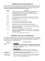
ERROR AND STATUS DISPLAYS
The Model 6745 Baby Scale s equipped with a diagnostic software program that tests various
portions of the scale’s circuitry and verifies proper operation. Should a problem be detected,
an error or status message will be displayed alerting the operator to that condition. The
following lists these errors and status displays and their meaning:
Display
8Q6
Meaning
2&$3
Motion is present when the scale is attempting to perform one of the
following operations: Power Up Zero or Zero Weight Display
Attempting to display a negative number greater than –99,999 or a
positive number greater than 99,999
Scale weight exceeds scale capacity
&$/LE
Indicates improper stored calibration data, calibration is necessary.
$G(UU
(UU$
The analog to digital circuit has failed. Consult your scale service
representative.
The analog to digital sample is invalid.
(UU$/
The load cell input is below the range of the scale.
(UU$+
The load cell input is above the range of the scale.
(((UU
NOVRAM failure. Consult the scale service representative.
WU/
Indicates an attempt to zero a weight outside the scale zero range.
2)
EDWWU\
(UU
(8QLW
2))
Indicates the remaing battery voltage expressed as a percentage (%) of
the total battery voltage.
General error, invalid keypad entry was attempted.
Displayed when the UNITS key is pressed and only a single weighing
units mode (0, pound & ounces or 1, kilograms) was selected during
setup and calibration.
Displayed to indicate the scale is turning off.
BEFORE YOU CALL FOR SERVICE
Your scale has been designed to provide you with years of trouble-free operation. In spite of
this, troubles sometimes happen. Before calling for service assistance you should make some
initial checks to verify that a problem does exist. The following describes several types of
symptoms along with suggested remedies.
Problem
Display does not
turn on
Possible Solutions
AC Operation:
Is the AC power cord fully inserted into the wall receptacle? Check
wall receptacle for proper AC power. Try another electrical appliance
in the same receptacle, does it work? Check the circuit breaker. Has
there been power failure?
Battery operation:
Check if batteries are installed and correctly. Are batteries
discharged? Replace if Alkaline or recharge if NI-CAD or NiMH.
Incorrect weight
displayed
Insure that the baby tray isn't touching an adjacent object. Have
proper operation procedures been followed?
Indicator will not
display weight
Refer to Error and Status Display section and make certain that the
2&$3message is not displayed. If so, and scale is not loaded,
consult your scale service representative.
17
PART IDENTIFICATION
18
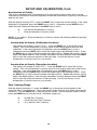
PART IDENTIFICATION, Cont.
19
PART IDENTIFICATION, Cont.
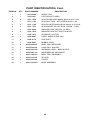
ITEM NO.
QTY
PART NUMBER
DESCRIPTION
1
1
2950-C118-1A
2
4
6013-0045
NUT HEX 1/4-20
3
2
6013-0245
NUT HEX #4-40
4
4
6021-0654
SCW PAN HEAD #6-32 X .250 PDMS
5
1
6021-1032
THUMB SCRW, 6-32 X 0.25
6
2
6021-1429
1/4-20 X 0.75 SHCS
7
2
6024-0039
WASHER LOCK HELICAL 1/4 REG.
8
2
6024-0126
WASHER #6 FLAT Z/P
9
4
6540-1011
LEVELER SCREW 1/4-20 X 1 S.S.
10
2
6610-2000
JACK SOCKET
11
2
6610-5007
CABLE CLIP
12
1
6610-5119
BATTERY HOLDER 6-C CELLS
13
1
6650-0018
GASKET MATERIAL 1” X 1/2” X 5 1/4”
14
4
6680-0004
WASHER LOCK INT. TOOTH #6 Z/P
15
2
6680-0052
WASHER LOCK #4 Z/P
16
4
6680-0214
RIVET POP, BH AL 5/32 DIA X 0.126 -.187 GR
17
1
8526-B214-08
LOAD CELL SPACER
18
1
8535-B050-0A
POWER CABLE
19
1
8535-B051-0A
CABLE: BATTERY
20
1
8535-B063-0A
SERIAL CABLE
21
1
8535-C054-0A
BASE WELDMENT
22
1
8535-C059-08
BATTERY MOUNT
23
1
8535-D043-0A
PCB ASSEMBLY – 6745 MAIN
24
1
8539-B254-0A
ASSEMBLY: CABLE, CALIBRATION SWITCH
25
1
8555-B166-08
BATTERY DOOR
20KG LOAD CELL CABLE ASSEMBLY
20
PART IDENTIFICATION, Cont.
21
PART IDENTIFICATION, Cont.
22
PART IDENTIFICATION, Cont.
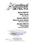
ITEM NO.
QTY
PART NUMBER
DESCRIPTION
1
1
593GR986
SERIAL TAG
2
1
593R1007
FACTORY SET LABEL
3
3
6021-1058
SCW TRUSS HEAD MACH-SCW 10-32 X .375
4
1
6021-1103
SCW HALF-DOG. SET SCREW #8-32 X .50
5
2
6021-1108
SCW FILLISTER MACH-SCW #10-32 X .375 S.S.
6
2
6021-1554
SCW SOCKET HD CAP SCW .025-20 – 1.50D
7
2
6024-0039
WASHER LOCK HELICAL 1/4 REG.
8
5
6024-1010
WASHER LOCK INT-TOOTH #10 Z/PL.
9
1
6560-1072
ADHESIVE, LOCTITE
10
1
6650-0087
LABEL: MADE IN THE USA
11
8
6680-0173
POP RIVET
12
1
6690-0001
BUBBLE LEVEL
13
2
8535-B060-08
BABY TRAY RECEIVER
14
1
8535-B062-08
LOAD CELL SPACER
15
1
8535-B065-08
WARNING LABEL – BABY SCALE
16
1
8535-B067-0A
WEIGHBRIDGE WELDMENT
17
1
8535-C066-0A
BABY TRAY ASSEMBLY
18
1
8535-D045-08
KEYPAD
19
1
8535-D053-08
COVER
20
1
8535-D058-0A
BASE ASSEMBLY
23
24