1
INCORPORATED
4282 Reynolds Drive
Hilliard Ohio, 43026
1(800) ACPOWER
www.vanner.com
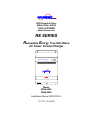
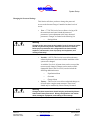
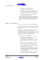
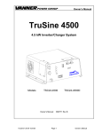
RE SERIES
Renewable Energy True Sine Wave
ERTE
R
ON
INV
R
RATO
GENE
UTILIT
Y
BATTE
RY
AC Power Inverter System
TEMP
ERAT
URE
CHAR
GER
AC Power Inverter/Charger
Owners Manual
OFF
CAUTION - Risk of Electric Shock, Do Not Remove Cover. No User Serviceable Parts Inside. Refer Servicing To Qualified Service Personnel.
CAUTION - Risk of Electric Shock, Both AC and DC Voltage Sources Are Terminated Inside This Equipment. Each Circuit Must Be Individually
Disconnected Before Servicing.
RE-4500
MULTI-MODE ALTERNATIVE ENERGY INVERTER
Models decribed
RE24-4500
RE48-4500
Part #D99988
07/17/01 12:20 PM
Revision 1.0
INCORPORATED
Notes
Copyright 2001
Vanner Inc.
4282 Reynolds Dr.
Hilliard Ohio 43026
Phone: (614) 771-271
FAX: 614-771-4904
www.vanner.com
RE Owners_Manual_Rev10d
RE-4500
Installation Manual
Rev 10d
D99988
INCORPORATED
Contents
Contents
1
2
3
4
5
Introduction............................................................................................................. 1-1
Specifications and Features .................................................................................. 2-1
Standard Features .................................................................................................... 2-5
Parts and Accessories .............................................................................................. 2-6
Important Safety Instructions ................................................................................ 3-1
Safety Instructions .................................................................................................... 3-3
General Precautions ................................................................................................. 3-4
Explosive Gas Precautions ....................................................................................... 3-5
Battery Precautions .................................................................................................. 3-5
Code Compliance ..................................................................................................... 3-6
Component Identification....................................................................................... 4-1
System Operation Description............................................................................... 5-1
Modes of Operation .................................................................................................. 5-5
Inverting................................................................................................................................5-5
Load Demand (Load Discover) ..................................................................................................... 5-5
Small Inverting .............................................................................................................................. 5-6
Normal Inverting ........................................................................................................................... 5-6
Surging .......................................................................................................................................... 5-6
Browning Out ................................................................................................................................ 5-6
Low Battery Shutdown.................................................................................................................. 5-7
Charging ...............................................................................................................................5-8
Battery Temperature Sensor ................................................................................................5-9
Generator Start Option .......................................................................................................5-10
Grid Interactive ...................................................................................................................5-11
Surplus Power ....................................................................................................................5-11
Generator Support..............................................................................................................5-12
Generator Start and Grid-Interactive..................................................................................5-12
Set Current .........................................................................................................................5-12
Bypass................................................................................................................................5-13
System Control ....................................................................................................... 5-13
On/Off Switch .....................................................................................................................5-13
Inverter Charger Control.....................................................................................................5-14
Inverter/Charger Controller...................................................................................................... 5-14
Display and Key Functions .......................................................................................................... 5-15
Moving Around the RE-ICC Menus.............................................................................................. 5-16
Turning The Inverter / Charger On and Off .................................................................................. 5-17
Menu Functions ........................................................................................................................... 5-18
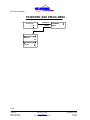
Display Menu ............................................................................................................................... 5-24
6
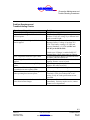
Preventive Maintenance and Trouble Shooting Procedures ............................... 6-1
Preventive Maintenance ........................................................................................... 6-1
Trouble Shooting Procedures ................................................................................... 6-1
Preliminary Checks................................................................................................... 6-2
Problem Symptoms and Troubleshooting Checks..................................................... 6-3
Appendix A: Warranty ........................................................................................................ 1
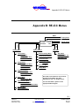
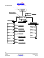
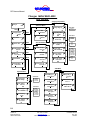
Appendix B: RE-ICC Menus ............................................................................................... 1
Appendix C: Settings ......................................................................................................... 1
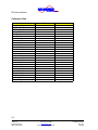
Alarm Listing................................................................................................................ 1
Calibration Data ........................................................................................................... 2
i
Copyright 2001
Vanner Inc.
4282 Reynolds Dr.
Hilliard Ohio 43026
Phone: (614) 771-271
FAX: 614-771-4904
www.vanner.com
RE Owners_Manual_Rev10d
RE-4500
Installation Manual
Rev 10d
D99988
INCORPORATED
RE Owners Manual
Appendix D: Application Notes ..........................................................................................1
Application Notes..........................................................................................................1
Applicable Documents..................................................................................................1
List of Tables
Table 2-1: RE-4500 Inverter/Charger Specifications.......................................................... 2-1
Table 4-1: Relay Configurations for Relay A...................................................................... 4-7
Table 4-2: Relay Configurations for Relay B...................................................................... 4-7
Table 4-3: Relay Configurations for Relay C...................................................................... 4-8
Table 4-4: Relay Configurations for Relay D...................................................................... 4-8
List of Charts
Chart 2-1: Inverter Power De-Rating Chart* ...................................................................... 2-3
Chart 2-2: Output Current Surge Fault Response Time @ 25°C* ...................................... 2-3
Chart 2-3: Current Regulation (Brownout) Mode Shutdown Time ...................................... 2-4
Chart 5-1: Output Current Surge Fault Response Time @ 25°C* ...................................... 5-6
Chart 5-2: Current Regulation (Brownout) Mode Shutdown Time ...................................... 5-7
List of Figures
Figure 4-1: Inverter/Charger Front and Side View ............................................................. 4-1
Figure 4-2: Inverter/Charger Front Panel Indicators........................................................... 4-3
Figure 4-3: DC Raceway Terminations.............................................................................. 4-6
Figure 4-4: AC Raceway Terminations .............................................................................. 4-6
Figure 5-1: Block Diagram................................................................................................. 5-2
Figure 5-2: Inverter/Charger Controller............................................................................ 5-15
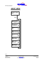
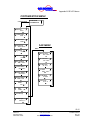
Figure 5-3: RE-ICC Menus .............................................................................................. 5-19
Figure 5-4: Main Menu .................................................................................................... 5-20
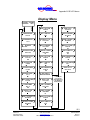
Figure 5-5: Inverter Menu ................................................................................................ 5-21
Figure 5-6: Display Menu ................................................................................................ 5-25
ii
Copyright 2001
Vanner Inc.
4282 Reynolds Dr.
Hilliard Ohio 43026
Phone: (614) 771-271
FAX: 614-771-4904
www.vanner.com
RE Owners_Manual_Rev10d
RE-4500
Installation Manual
Rev 10d
D99988
INCORPORATED
Introduction
1
Introduction
Thank you for purchasing a Vanner RE-4500 Renewable
Energy Inverter System. We are confident that you will be
satisfied with its performance and its many features. With
proper installation and care, you can look forward to years of
service from this high performance product.
“RE-4500” stands for Renewable Energy 4500 Watt, Inverter
System. The specific model numbers covered in this document
are the “RE48-4500” and “RE24-4500” which designate
48VDC or 24VDC respectively.
The RE SERIES is a family of dependable inverters designed
to meet the service requirements of the Renewable Energy
market and produce true sine wave AC output power.
This document will describe the operation and technical
specifications of the RE24-4500 and accessories offered in this
product family. We suggest that you acquaint yourself with this
model inverter/charger and any optional accessories that you
have purchased before proceeding with this manual. If you
require additional information please contact your dealer, or
contact us directly at 1-800-227-6937 (800 AC POWER).
WARNING:
Before you install and use your RE SERIES Inverter/Charger be sure
to read and save these safety instructions.
WARNING:
The RE-4500 is not designed to be a part of Life Supporting or Life
Sustaining Equipment. If the Unit is to be used in such an
application, please contact Vanner Inc. at 1-800-ACPOWER.
The RE SERIES product line is designed to meet the
requirements of a variety of applications.
1-1
Copyright 2001
Vanner Inc.
4282 Reynolds Dr.
Hilliard Ohio 43026
Phone: (614) 771-271
FAX: 614-771-4904
www.vanner.com
RE Owners_Manual_Rev10d
RE-4500
Installation Manual
Rev 10d
D99988
INCORPORATED
RE Owners Manual
Save these instructions!
Please note your model and serial number here for future
reference.
Model No.
Serial No.
Date of Installation
This document describes the operation, technical specifications
and installation procedures for the RE-4500 Inverter/Charger
System. If you require additional information please contact
your dealer or contact Vanner at 1-800-AC POWER (1-800227-6937).
1-2
Copyright 2001
Vanner Inc.
4282 Reynolds Dr.
Hilliard Ohio 43026
Phone: (614) 771-271
FAX: 614-771-4904
www.vanner.com
RE Owners_Manual_Rev10d
RE-4500
Installation Manual
Rev 10d
D99988
INCORPORATED
Specifications and Features
2
Specifications and Features
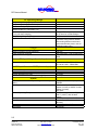
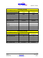
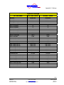
Table 2-1: RE-4500 Inverter/Charger Specifications
AC Power Output (Inverter Output)
Rated Output Watts (-40 to +25°C)
Continuous Output at 25°C (77°F)
Continuous Output at 40°C (104°F)
Continuous Output at 50°C (122°F)
Continuous Output at 60°C (140°F)
Max Continuous Output on L1 or L2
3 Second Surge Output (at 24 VDC input, and 25ºC)
AC Maximum Output Fault Current
Output Waveform
Output Voltage, Single Phase, 3 Wire
Output Frequency
Power Factor
Charging or Grid Interactive Power Factor
% of Rated Charger Current Available at Full Charger
Voltage
Total Harmonic Distortion (THD)
AC Output Wiring Method
4500 Watts
4500 Watts
3650 Watts
3250 Watts
3200 Watts
26.5 Amps (Electronically current
limited)
10000 VA
56.25 Arms
(Inverter shuts down in 1/60 sec)
True Sine Wave
120/240 Vrms ±5.0%
60 Hz ± 0.01 Hz
-1 to 1
Unity
100%
5% Maximum
Hardwire Terminal Strip
AC Transfer Switch
Amperage Rating
Transfer Speed (a function of load)
From Inverter to Utility Power
From Utility Power to Inverter w/ Grid Tie Enabled
From Utility Power to Inverter w/ Grid Tie Disabled
30 Amp 240 Volt
16 milliseconds to 0.5 second
(approx.)
16 ms
1 second
40 ms
2-1
Copyright 2001
Vanner Inc.
4282 Reynolds Dr.
Hilliard Ohio 43026
Phone: (614) 771-271
FAX: 614-771-4904
www.vanner.com
RE Owners_Manual_Rev10d
RE-4500
Installation Manual
Rev 10d
D99988
INCORPORATED
RE Owners Manual
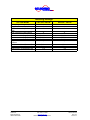
AC Operating Ratings
AC Operating Voltage (Utility Interactive)
AC Operating Voltage (Stand-alone)
AC Maximum Output Current
AC Maximum Output Fault Current
(Measured when L1 is shorted to L2.)
AC Maximum Input Current
(From grid when charging)
AC Operating Frequency Range
Output Neutral to Ground
211.8 to 264 Vrms
211.8 to 264 Vrms
18.75 Arms
56.25 Arms
30 amp APM rating
18.75 Arms for Inverter/Charger
59.75 Hz to 60.25 Hz
Not Bonded
(Good AC wiring practice dictates
that bonding between neutral and
ground should take place in the AC
distribution panel only.)
Charger
Maximum Charge Current Supported
Types of Charge supported
Types of Batteries Supported
100 ADC
Bulk, Absorption, Float, and Equalize
Lead Acid: Flooded-Cell, GEL, or
AGM
DC Input Voltage (Inverter Input)
DC Input Voltage Range
21.0 to 31.0 VDC - RE24-4500
41.0 to 62.0 VDC - RE48-4500
DC Input Current at 24VDC (Inverter Input)
Inverter OFF
Inverter in Load Demand (No AC load)
Inverter ON with no AC load
Inverter with full load at 22VDC (4500W @ 25°)
1 ma
0.5 amps
2.0 amps
225 amps
System
Generator Start & Low Battery Warning Control Relays
Rating
Efficiency
Ambient Operating Temperature
Cooling Air
Enclosure
Dimensions
Unit Weight
2 Amps 120 VAC / 2 Amps up to
100VDC
80% Nominal (at 22VDC for 24V
System, full load, at 44VDC for 48V
System, full load)
90% peak
-40° to +40°C (-40 to +104°F) (to
+60°C (+140°F) with de-rated
output)
Thermostatically Controlled Fan
Powder-Coated Aluminum / Wall
Mounting
29½ H x 20½ W x 9¼ D
95 pounds
2-2
Copyright 2001
Vanner Inc.
4282 Reynolds Dr.
Hilliard Ohio 43026
Phone: (614) 771-271
FAX: 614-771-4904
www.vanner.com
RE Owners_Manual_Rev10d
RE-4500
Installation Manual
Rev 10d
D99988
INCORPORATED
Specifications and Features
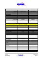
Watts (Output)
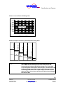
Chart 2-1: Inverter Power De-Rating Chart*
5000
4500
4000
3500
3000
2500
2000
1500
1000
500
Operating Range
-50 -40 -30 -20 -10
0 10 20 30 40 50 60 70 80
Temperature in Degrees C
10
Seconds
*Note:
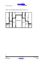
56.25 Arms
37.50 Arms
3
Seconds
1 Second
79.55 Arms
Indefinitely
28.13 Arms
18.75 Arms
Chart 2-2: Output Current Surge Fault Response Time @ 25°C*
.01667
seconds
0.0000514
Seconds
The RE-4500 Inverter will try to power the load as per the chart
above. When the load exceeds the inverter's rated output the
Inverter/Charger Indicator LED will turn Orange. The current limit
circuit will operate in the manner indicated above, and will reduce the
AC Output Voltage as needed to keep the AC Output Current from
exceeding specifications. If the output voltage is outside the limits
shown in Chart 2-3, the inverter will shut off and the Inverter/Charger
LED will turn Red.
2-3
Copyright 2001
Vanner Inc.
4282 Reynolds Dr.
Hilliard Ohio 43026
Phone: (614) 771-271
FAX: 614-771-4904
www.vanner.com
RE Owners_Manual_Rev10d
RE-4500
Installation Manual
Rev 10d
D99988
INCORPORATED
RE Owners Manual
60 Vrms
420 Vrms
330 Vrms
254 Vrms
211 Vrms
120 Vrms
Chart 2-3: Current Regulation (Brownout) Mode Shutdown Time
Indefinitely
10
Seconds
10
Seconds
.033
Second
.033
Second
.01667
Second
.01667
Second
2-4
Copyright 2001
Vanner Inc.
4282 Reynolds Dr.
Hilliard Ohio 43026
Phone: (614) 771-271
FAX: 614-771-4904
www.vanner.com
RE Owners_Manual_Rev10d
RE-4500
Installation Manual
Rev 10d
D99988
INCORPORATED
Specifications and Features
Standard Features
•
True sine wave single phase 3 wire 240 VRMS output.
•
Unity Power Factor Corrected Battery Charger for less AC
Input Distortion, accommodating Lead Acid, Flooded-Cell,
GEL, and AGM types of batteries.
•
True single phase three wire 240VRMS output that can be
used with Multiwire branch circuits, without needing the
load rewiring (required by many single phase inverters).
•
Total harmonic distortion less than 5% for all loads up to
the Surge Output Rating.
•
Reliable electronic protection designed to handle output
short-circuits and output overloads.
•
Terminal block for hardwiring the AC outputs.
•
Automatic shutoff for low or high battery voltage,
overload, or over-temperature.
•
Relay Output circuits, providing Normally Open (NO) and
Normally Closed (NC) control for activating external
devices and alarms.
•
Indicator lights for Inverter, Temperature, Battery,
Generator, and Utility status.
•
Thermostatically controlled cooling fan.
2-5
Copyright 2001
Vanner Inc.
4282 Reynolds Dr.
Hilliard Ohio 43026
Phone: (614) 771-271
FAX: 614-771-4904
www.vanner.com
RE Owners_Manual_Rev10d
RE-4500
Installation Manual
Rev 10d
D99988
INCORPORATED
RE Owners Manual
Parts and Accessories
Part
Number
Name
Description
RE-ICC/LCD
Remote Display
RE24-4500S
24V RE-4500 with a
Small Inverter Board
Inverter/Charger Controller – changes and
displays the programmable settings inside the
RE-4500.
This option enables greater efficiency when the
inverter is providing power for a light load (less
than 75 watts).
RE-ACM
AC Control Module
Includes most requirements for utility, load,
bypass, and AC generator connections, breakers,
and switches in a convenient assembly.
RE-DCM
DC Control Module
Includes most requirements Solar, Battery,
Auxiliary DC Loads, Charge Controllers,
Disconnects, and connections for the DC source
and loads in a convenient assembly.
RE-BTS1
B/T Sensor
RE-SLM
Sun Lynx Module
Battery Temperature Sensor – an optional sensor
available to more accurately monitor the
condition of batteries in the system.
Configures the system for “battery-less
operation”. This module is used to connect to
the Solar Array instead of the RE-DCM used in
a Battery populated system.
Models:
RE48-DCM
RE24-DCM
Model:
RE48-SLM
2-6
Copyright 2001
Vanner Inc.
4282 Reynolds Dr.
Hilliard Ohio 43026
Phone: (614) 771-271
FAX: 614-771-4904
www.vanner.com
RE Owners_Manual_Rev10d
RE-4500
Installation Manual
Rev 10d
D99988
INCORPORATED
Important Safety Instructions
3
WARNING:
Important Safety Instructions
Before you install and use your RE-SERIES AC Power Inverter, read
and save these safety instructions!
This manual contains important safety and operating
instructions for the Vanner Incorporated RE-4500 Power
Inverter that shall be followed during installation and
maintenance of the inverter as prescribed by Underwriters
Laboratories (UL). The RE-4500 inverter is listed as compliant
with UL 1741 Power Conditioning Units for use in Residential
Photovoltaic Power Systems.
Warning Labels
Please READ ME
It should be noted that hazardous voltages are associated with
this product. This unit has connections to both DC at lethal
amperages and AC at lethal amperages and voltages.
Installation should only be done by qualified personnel and in
compliance with local regulations and codes.
Special care must be taken in working around the RE-4500
Inverter/Charger System in order to avoid hazardous voltages
and currents.
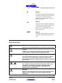
NOTE:
In order to reduce the risk of damage to personnel or equipment,
please read all instructions in this manual, particularly warnings
noted by the following symbols.
3-1
Copyright 2001
Vanner Inc.
4282 Reynolds Dr.
Hilliard Ohio 43026
Phone: (614) 771-271
FAX: 614-771-4904
www.vanner.com
RE Owners_Manual_Rev10d
RE-4500
Installation Manual
Rev 10d
D99988
INCORPORATED
RE Owners Manual
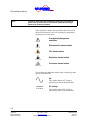
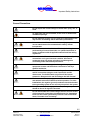
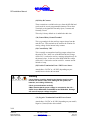
These symbols are used to note procedures that if not closely
followed could lead to loss of life or damage to equipment or
property due to electrocution.
Electrocution hazard exists
Fire hazard exists
A potentially dangerous
condition
Explosive hazard exists
Corrosive hazard exists
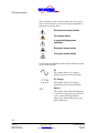
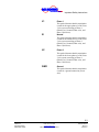
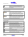
The following are additional symbols used in identifying other
aspects of the RE-4500.
AC
This symbol denotes AC Voltage is
potentially present on this termination.
DC Voltage
This symbol denotes DC Voltage is
potentially present on this termination.
L1
Phase 1
This symbol denotes that this termination
is used for the upper phase of a 240 Vrms
3 wire system consisting of Phase 1
(Black wire), Neutral (White wire), and
Phase 2 (Red wire).
3-2
Copyright 2001
Vanner Inc.
4282 Reynolds Dr.
Hilliard Ohio 43026
Phone: (614) 771-271
FAX: 614-771-4904
www.vanner.com
RE Owners_Manual_Rev10d
RE-4500
Installation Manual
Rev 10d
D99988
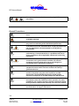
INCORPORATED
Important Safety Instructions
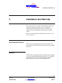
N
Neutral
This symbol denotes that this termination
is used for the middle wire of a 240 Vrms
3 wire system consisting of Phase 1
(Black wire), Neutral (White wire), and
Phase 2 (Red wire).
L2
Phase 2
This symbol denotes that this termination
is used for the lower phase of a 240 Vrms
3 wire system consisting of Phase 1
(Black wire), Neutral (White wire), and
Phase 2 (Red wire).
GND
Ground
This symbol denotes that this termination
is used for a ground connection (Green
wire).
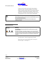
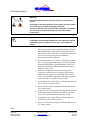
Safety Instructions
Caution
Read owners manual BEFORE wiring or powering up the RE-4500.
Caution
DO NOT cover or obstruct ventilation openings. DO NOT mount in
a zero-clearance compartment. Overheating may result.
Warning
Under high ambient temperature / high-power-output conditions
some parts of the inverter may become hot enough to cause
burns. The unit should be installed so that it is not to be contacted
by personnel.
Warning
This equipment employs components that tend to produce arcs
and sparks. To prevent fire or explosion, DO NOT install in
confined areas or compartments that contain batteries or
flammable gases and materials.
Warning
Improper use of this product may result in risk of electrical shock.
Both AC and DC voltage sources are terminated inside this
equipment.
3-3
Copyright 2001
Vanner Inc.
4282 Reynolds Dr.
Hilliard Ohio 43026
Phone: (614) 771-271
FAX: 614-771-4904
www.vanner.com
RE Owners_Manual_Rev10d
RE-4500
Installation Manual
Rev 10d
D99988
INCORPORATED
RE Owners Manual
Battery connections are for disconnection only, NOT for current
interruption.
General Precautions
Do not expose the inverter/charger to direct water spray, rain, or
snow.
To reduce the risk of a fire hazard, do not cover or obstruct the
ventilation openings.
Do not install the inverter in a zero clearance compartment. This
may result in overheating and/or diminished performance.
To avoid the risk of fire, electrical shock, or injury to persons, do
not use attachments not recommended or sold by Vanner
Incorporated.
Vanner recommends that all AC and DC electrical wiring be
performed by a licensed electrician or a qualified technician to
ensure compliance with all applicable national and local wiring
regulations.
To avoid a risk of fire and/or electrical shock, always verify wiring
connections are in good electrical condition. All external
conductors must use proper wire size to avoid dangerous
overheating and/or diminished performance.
If the inverter has been dropped or damaged in any way, do not
operate the inverter until it has been verified to be safe by a
qualified technician.
To reduce the risk of electrical shock, always disconnect the AC
and DC connections using the code required AC and DC
disconnects. The On/Off switch only turns off the Inverter
electronics. Dangerous AC and DC Voltages Are Still Present!
The inverter must be properly grounded in accordance with local
and national codes and ordinances before operation. For most
installations, the negative (ground) conductor should be bonded
to the grounding system at one and only one point in the system.
For optimum inverter/charger performance, battery temperature
should be above 32 degrees Fahrenheit.
3-4
Copyright 2001
Vanner Inc.
4282 Reynolds Dr.
Hilliard Ohio 43026
Phone: (614) 771-271
FAX: 614-771-4904
www.vanner.com
RE Owners_Manual_Rev10d
RE-4500
Installation Manual
Rev 10d
D99988
INCORPORATED
Important Safety Instructions
Do not disassemble the inverter/charger. See the service section
of this manual for instructions on obtaining service. Attempting
to service the inverter yourself may result in a risk of electrical
shock, fire and/or loss of warranty.
Always use service disconnects to break the circuit before
attempting any kind of servicing of the RE-4500. DO NOT attempt
to service the unit while still actively connected to a power
source of any kind.
Explosive Gas Precautions
This equipment contains components, which tend to produce arcs
or sparks. To prevent fire or explosion, do not install in
compartments containing batteries or flammable materials, or in
locations that require ignition protected equipment. This includes
any space containing gasoline-powered machinery, fuel tanks, or
joints, fittings, or other connections between components of the
fuel system.
To reduce the risk of battery explosion, follow these instructions,
the battery manufacturer instructions, and the instructions of the
manufacturer of the equipment in which the battery is installed.
Working near a lead-acid battery is dangerous. Batteries generate
explosive gases during normal battery operation.
Battery Precautions
Always have someone within range of your voice to come to your
aid when you work near a lead-acid battery.
Have close access to plenty of fresh water and soap in case
battery acid contacts skin, clothing, or eyes.
Always wear complete eye protection and clothing protection.
Avoid touching eyes while working near batteries.
If battery acid contacts skin or clothing, wash immediately with
soap and water. If acid enters eye, immediately flood eye with
running cold water for at least 20 minutes. Get medical attention
immediately.
NEVER smoke or allow a spark or flame near a battery. Gases
produced by batteries are explosive.
3-5
Copyright 2001
Vanner Inc.
4282 Reynolds Dr.
Hilliard Ohio 43026
Phone: (614) 771-271
FAX: 614-771-4904
www.vanner.com
RE Owners_Manual_Rev10d
RE-4500
Installation Manual
Rev 10d
D99988
INCORPORATED
RE Owners Manual
Be careful when working with metal tools around batteries.
Potentials exist for sparks or short-circuit of the battery or other
electrical part which could cause an explosion.
Before attempting any sort of wiring for the DC supply to the
Inverter, turnoff the DC disconnect associated with the Batteries.
For Safety, ALWAYS check the operation of the disconnect with a
voltmeter!
In addition to the lethal current associated with the batteries, care
must be taken to avoid any potential problems or explosions from
the batteries. ALWAYS comply with the battery manufacturer’s
and local code requirements/guidelines for the installed battery
system.
Code Compliance
Vanner Model RE-4500 is certified by Underwriter’s
Laboratory to meet UL listing 1741 for Photovoltaic Systems,
and complies with IEEE 929 and the National Electric Code
Article 690, Solar Photovoltaic Systems.
3-6
Copyright 2001
Vanner Inc.
4282 Reynolds Dr.
Hilliard Ohio 43026
Phone: (614) 771-271
FAX: 614-771-4904
www.vanner.com
RE Owners_Manual_Rev10d
RE-4500
Installation Manual
Rev 10d
D99988
INCORPORATED
Component Identification
4
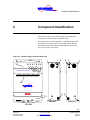
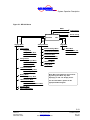
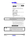
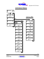
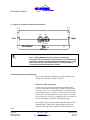
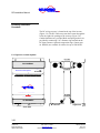
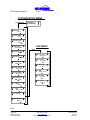
Component Identification
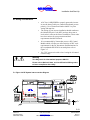
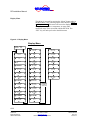
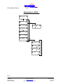
This section will give the reader an idea as to location and
description of various features of the RE-4500.
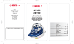
Note that at the top of the unit there is a parallel raceway with
terminations for connecting DC Power and Control Wiring.
The bottom of the unit contains another parallel raceway for
AC Power Wiring connections.
Figure 4-1: Inverter/Charger Front and Side View
11
12
1
2
2
1
INVE
RTER
TEMP
ERAT
URE
ON
CHAR
GER
TY
UTILI
BATT
ERY
AC Power Inverter System
GENE
RATO
R
10 9 8 7 6 5 4
OFF
14
CAUTION - Risk of Electric Shock, Do Not Remove Cover. No User Serviceable Parts Inside. Refer Servicing To Qualified Service Personnel.
CAUTION - Risk of Electric Shock, Both AC and DC Voltage Sources Are Terminated Inside This Equipment. Each Circuit Must Be Individually
Disconnected Before Servicing.
RE-4500
3 3
MULTI-MODE ALTERNATIVE ENERGY INVERTER
13
28
29
28
Left View
11
28
Right View
Front View
4-1
Copyright 2001
Vanner Inc.
4282 Reynolds Dr.
Hilliard Ohio 43026
Phone: (614) 771-271
FAX: 614-771-4904
www.vanner.com
RE Owners_Manual_Rev10d
RE-4500
Installation Manual
Rev 10d
D99988
INCORPORATED
RE Owners Manual
(1) Knockout for High Current DC Wiring
This knockout provides for the routing and termination of high
capacity DC cables from batteries, RE-SLM, RE-DCM to the
RE-4500 Inverter/Charger.
This knockout provides access (from either the right side or the
left side of the inverter) to the DC Wiring Raceway.
This knockout matches up with the high capacity DC knockout
on Vanner accessories such as the DC Control Module (REDCM), the RE48-SLM (Sun Lynx Module), and the AC
Control Module (RE-ACM). This is a standard size 2 ½”
conduit knockout.
(2) Knockout for Low Current DC Control Wiring
These knockouts provide for the routing and termination of
low capacity DC Control Wiring.
These knockouts provide access (from either the right side or
the left side of the inverter) to the DC Wiring Raceway.
These knockouts match up with the low current DC/Control
knockouts on Vanner accessories such as the DC Control
Module (RE-DCM), the RE-SLM (Sun Lynx Module), and the
AC Control Module (RE-ACM). This is a standard size ¾”
conduit knockout.
(3) Knockout for AC Wiring
This knockout provides for the routing and termination of AC
Wiring.
This knockout provides access (from either the right side or the
left side of the inverter) to the AC Wiring Raceway.
This knockout matches up with the AC knockout on Vanner
accessories such as the AC Control Module (RE24-ACM), the
RE48-SLM (Sun Lynx Module), and the DC Control Module
(RE24-DCM). This is a standard size 1 ¼ “ conduit knockout.
4-2
Copyright 2001
Vanner Inc.
4282 Reynolds Dr.
Hilliard Ohio 43026
Phone: (614) 771-271
FAX: 614-771-4904
www.vanner.com
RE Owners_Manual_Rev10d
RE-4500
Installation Manual
Rev 10d
D99988
INCORPORATED
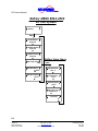
Component Identification
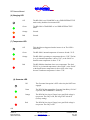
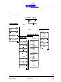
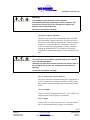
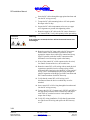
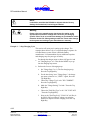
Figure 4-2: Inverter/Charger Front Panel Indicators
4
ERT
ER
RE
RG
ER
ON
INV
CHA
TOR
ATU
PER
ERA
GEN
TEM
UTIL
ITY
System
BAT
TER
Y
10 9 8 7 6 5
OFF
(4) Inverter LED
Off
The RE-4500 is not inverting, however, if all of the other front
panel indicators are also off, then the RE-4500 is OFF.
Green
The RE-4500 is Inverting, Charging or Grid Interactive.
If blinking, it is Inverting and in “Load Demand.”
Orange
The RE-4500 is Inverting and in “brownout” and/or is constantly
supplying its maximum current.
If the system is in “Charging” mode and this LED is orange, the
charger is supplying its maximum current.
Red
The RE-4500 has shutdown due to a “brownout” Condition.
(5) ON/OFF Switch (and RESET Switch)
The ON/OFF Switch is a two-position switch used to turn the
inverter electronics ON and OFF. This ON/OFF switch can
also be used to RESET any faults that might be present.
These faults are displayed on the Indicator LEDs and in the
ALARM Menu of the optional Inverter. These faults will be
displayed until the Inverter is RESET by turning it “OFF” and
then back “ON”.
If the fault is serious enough, the inverter will automatically
shut itself OFF. Likewise, the inverter can be RESET by
turning the ON/OFF Switch “OFF”, and then back “ON”.
4-3
Copyright 2001
Vanner Inc.
4282 Reynolds Dr.
Hilliard Ohio 43026
Phone: (614) 771-271
FAX: 614-771-4904
www.vanner.com
RE Owners_Manual_Rev10d
RE-4500
Installation Manual
Rev 10d
D99988
INCORPORATED
RE Owners Manual
(6) Charging LED
Off
The RE-4500 is not CHARGING or in a GRID-INTERACTIVE
mode or they both have been turned OFF.
Green
The RE-4500 is CHARGING or in a GRID-INTERACTIVE
mode.
Orange
Unused.
Red
Unused.
(7) Temperature LED
Off
This should never happen when the inverter is on. The LED is
burned-out.
Green
The RE-4500’s internal temperature is between -40 and +35 °C.
Orange
The RE-4500 is operating at a temperature above +35°C. The fan
is on, its internal temperature is above 35 °C, or the “Brick” or
Small Inverter temperature is above 75 °C.
Red
The RE-4500 has shutdown due to over temperature. The fan is
FULLY on, its internal temperature is above 60°C, or the “Brick”
or the Small Inverter temperature is above 90°C or the Large
Inverter Transformer temperature is above 75°C.
(8) Generator LED
Off
The Generator Start option is OFF or the relay has NOT been
engaged.
Green
The RE-4500 has engaged the Generator Start Relay, Grid AC
is present, and CHARGING is underway.
Orange
The RE-4500 is trying to Charge, but a good Grid voltage is
not present. The relay is ON, but will go OFF after 90 S
(Factory setting).
Red
The RE-4500 is trying to Charge, but a good Grid voltage is
not present. The relay is OFF.
4-4
Copyright 2001
Vanner Inc.
4282 Reynolds Dr.
Hilliard Ohio 43026
Phone: (614) 771-271
FAX: 614-771-4904
www.vanner.com
RE Owners_Manual_Rev10d
RE-4500
Installation Manual
Rev 10d
D99988
INCORPORATED
Component Identification
(9) Battery LED
Off
Should only happen when the RE-4500 is turned off.
Green
The Battery Voltage is Good. (Between 22 and 31 VDC /
Factory settings).
Orange
The Battery Voltage is above the Low Battery Shutdown value
(Factory setting 21 VDC), but it is below the Low Battery
Warning value (Factory setting / 22 VDC). The Low Battery
Warning relay is ON.
Red
The RE-4500 has shutdown because either the Battery Voltage
is above the High Battery Shutdown value (Factory setting 31
VDC) or is below the Low Battery Shutdown value (Factory
setting / 21 VDC). If the latter case is true, then the Low
Battery Warning relay is ON or the battery is “dead.”
(10) Utility LED
Off
The Inverter is OFF.
Green
The RE-4500 is attached to the Grid. The Grid frequency and
voltage are within preset limits, and the transfer relay is engaged.
The inverter is in either BYPASS, CHARGING, or GRIDINTERACTIVE modes.
Orange
The RE-4500 is waiting to phase-lock. The Grid frequency and
voltage are both within preset limits. When the AC good timeout
has expired (Factory setting 90 S) then the bypass relay will
engage and the LED will turn green.
Red
An unacceptable grid condition is present. The voltage, the
frequency, or both are outside acceptable limits.
(11) Mounting Bolt Slots
4-5
Copyright 2001
Vanner Inc.
4282 Reynolds Dr.
Hilliard Ohio 43026
Phone: (614) 771-271
FAX: 614-771-4904
www.vanner.com
RE Owners_Manual_Rev10d
RE-4500
Installation Manual
Rev 10d
D99988
INCORPORATED
RE Owners Manual
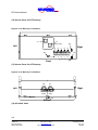
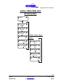
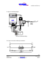
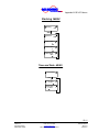
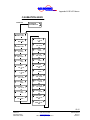
(12) Access Cover for DC Raceway
Figure 4-3: DC Raceway Terminations
-
23
22
+
Left
24
(48VDC or 24VDC)
Right
+
21 20
16
17
18
19
25
15
NO
NO
+VDC
NC
C
NC
C
Gnd
NO
NO
C
NC
C
NC
(48VDC or 24VDC)
A
B
C
D
Front
(13) Access Cover for AC Raceway
Figure 4-4: AC Raceway Terminations
26
27
Left
Right
L1
N
GND
L2
AC OUT
L1
N
GND
L2
AC IN
29
28
Bottom
(14) Air Intake Vents
4-6
Copyright 2001
Vanner Inc.
4282 Reynolds Dr.
Hilliard Ohio 43026
Phone: (614) 771-271
FAX: 614-771-4904
www.vanner.com
RE Owners_Manual_Rev10d
RE-4500
Installation Manual
Rev 10d
D99988
INCORPORATED
Component Identification
(15) Battery Temperature Sensor Monitor Port
At this time, this is an option on 24 Volt systems only!
This RJ11 Port enables battery bank temperature monitoring
with the optional Vanner Battery Temperature Sensor (Vanner
Part Number RE-BTS1). This sensor is used for optimizing
battery charging efficiency, extending battery life, and battery
fault monitoring.
Warning
This connector is for the Battery Temperature Sensor Only!
Attaching any other device to this connector can result in loss of
life, damage to the system, and voiding of your manufacturers
warranty.
Check your terminations carefully!
(16) Relay A Contacts – Low Batt
These terminals are available to the user from the RE-4500 and
can be used for several programmable functions. These
functions are listed in Table 4-1: Relay Configurations for
Relay A. The Factory Setting for this set of contacts is for Low
Battery Alarm. These three Terminals are designated as
Normally Open, Common, and Normally Closed.
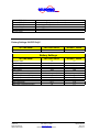
Table 4-1: Relay Configurations for Relay A
Function
Configuration
Comments
Low Battery Alarm
Form C
Factory Setting
(17) Relay B Contacts
These terminals are available to the user from the RE-4500 and
can be used for several programmable functions. These
functions are listed in Table 4-2: Relay Configurations for
Relay B. There is no assigned condition for this set of contacts
at this time. These three Terminals are designated as Normally
Open, Common, and Normally Closed.
Table 4-2: Relay Configurations for Relay B
Function
Configuration
Not Assigned
Form C
Comments
4-7
Copyright 2001
Vanner Inc.
4282 Reynolds Dr.
Hilliard Ohio 43026
Phone: (614) 771-271
FAX: 614-771-4904
www.vanner.com
RE Owners_Manual_Rev10d
RE-4500
Installation Manual
Rev 10d
D99988
INCORPORATED
RE Owners Manual
(18) Relay C Contacts – Gen. Start
These terminals are available to the user from the RE-4500 and
can be used for several programmable functions. These
functions are listed in Table 4-3: Relay Configurations for
Relay C. The Factory Setting function for this set of contacts is
Generator Start. These three Terminals are designated as
Normally Open, Common, and Normally Closed.
Table 4-3: Relay Configurations for Relay C
Function
Configuration
Comments
Generator Start
Form C
Factory Default
(19) Relay D Contacts
These terminals are available to the user from the RE-4500 and
can be used for several programmable functions. These
functions are listed in Table 4-4: Relay Configurations for
Relay D. There is no Factory Setting function for this set of
contacts. These three Terminals are designated as Normally
Open, Common, and Normally Closed.
Table 4-4: Relay Configurations for Relay D
Function
Not assigned
Configuration
Form C
Comments
(20) Control Relay Ground Terminal
This terminal supplies 24VDC Ground for use in powering
relays in the RE24-4500 Inverter system.
(21) Control Relay Auxiliary VDC Output Terminal
In the RE24-4500, this terminal supplies 24VDC (current
limited to 1 Amp) for use in wetting 24VDC relays contacts. In
the RE48-4500 this terminal provides 48VDC for use in
wetting 48VDC contacts.
4-8
Copyright 2001
Vanner Inc.
4282 Reynolds Dr.
Hilliard Ohio 43026
Phone: (614) 771-271
FAX: 614-771-4904
www.vanner.com
RE Owners_Manual_Rev10d
RE-4500
Installation Manual
Rev 10d
D99988
INCORPORATED
Component Identification
(22) Positive Termination From DC Power Source
Attach either +24 VDC or 48 VDC (depending on your model)
Positive feed to this terminal
Warning
Check Polarity Carefully! Attaching the Negative supply to this
terminal can result in loss of life, damage to the system, the
batteries, and voiding of Warranty.
Check your terminations carefully!
!!Make Certain that the proper voltage is connected to the unit –
24VDC for the RE24-4500, and 48VDC for the RE48-4500. Damage
will result if improper voltage is applied.
(23) Negative Termination From DC Power Source
Attach either +24 VDC or 48 VDC (depending on your model)
Negative (Ground) feed to this terminal.
Warning
This terminal is grounded to the inverter Chassis
Check Polarity Carefully! Attaching the Positive supply to this
terminal can result in loss of life, damage to the system, the
batteries, and voiding of Warranty.
Check your terminations carefully!
(24) Serial Control Connector
This RJ-11 jack is for serial communication between the RE4500 and the remote display (Inverter / Charger Controller) –
Vanner Part RE-ICC or RS-232 Control/Programming Cable.
Alternately this connector can be used to communicate with a
computer using RE-ICC For Windows using the Vanner
provided communications cable which comes with ICC for
Windows.
Warning
This connector is for the RE-ICC Remote Display or the Vanner
Serial Communications cable! Attaching any other device to this
connector can result in loss of life, damage to the system, and
voiding of the manufacturers Warranty.
Check your terminations carefully!
4-9
Copyright 2001
Vanner Inc.
4282 Reynolds Dr.
Hilliard Ohio 43026
Phone: (614) 771-271
FAX: 614-771-4904
www.vanner.com
RE Owners_Manual_Rev10d
RE-4500
Installation Manual
Rev 10d
D99988
INCORPORATED
RE Owners Manual
(25) Option Connector
This connector is supplied to support the Generator Option in
the Vanner AC Control Module (RE-ACM) please review the
manual supplied with the RE-ACM unit for more information.
(26) AC Output Terminations
Terminations for the Load to be connected to the RE-4500 are
connected to the proper terminals: L1 is Phase 1, N is Neutral,
and L2 is Phase 2 of a split phase system.
Warning
Check Polarity Carefully! Improper wiring of these terminations can
result in loss of life, damage to this system, damage to connected
loads, and voiding of Warranty.
Check your terminations carefully!
(27) AC Input Terminations
Terminations for the Utility to be connected to the RE-4500 are
connected to the proper terminals: L1 is Phase 1, N is Neutral,
L2 is Phase 2, and GND is Chassis Ground for the split phase
Grid connection.
Warning
Check Polarity Carefully! Improper wiring of these terminations can
result in loss of life, damage to this system, damage to connected
loads, and voiding of Warranty.
Check your terminations carefully!
Note
The Output Neutral is not bonded to Ground at the Inverter.
(28) Chassis Ground Bonding Lug
The Chassis Ground Bonding Lug is used to create a tie point
for connecting the Chassis of the RE-4500 to ground.
(29) Cooling Fan
The cooling air exhaust fan is located on the Bottom of the
inverter. Air is brought in through the front cooling slots as
well as the rear plenum and exhausted at the bottom of the
4-10
Copyright 2001
Vanner Inc.
4282 Reynolds Dr.
Hilliard Ohio 43026
Phone: (614) 771-271
FAX: 614-771-4904
www.vanner.com
RE Owners_Manual_Rev10d
RE-4500
Installation Manual
Rev 10d
D99988
INCORPORATED
Component Identification
inverter. Always allow a minimum of 12” clearance (30.48 cm)
below the Inverter to insure proper cooling.
4-11
Copyright 2001
Vanner Inc.
4282 Reynolds Dr.
Hilliard Ohio 43026
Phone: (614) 771-271
FAX: 614-771-4904
www.vanner.com
RE Owners_Manual_Rev10d
RE-4500
Installation Manual
Rev 10d
D99988
INCORPORATED
System Operation Description
5
System Operation
Description
This section of the Owner’s manual will cover command and
control of the system, and also describe the different
components that make up the RE-4500.
The RE-4500 is an Inverter/Charger system that has the
capability of drawing power from the grid or selling excess
power back to the grid, and creating split-phase 240 VAC from
a nominal 24 VDC source (RE24-4500), or a nominal 48VDC
source (RE48-4500). This DC source can consist of both
Photovoltaic Modules and lead acid batteries of Flooded Cell,
Gel Cell, or AGM types.
Warning
It is important not to mix types of batteries in a string. Mixing
different types of batteries could result in death, explosion, or fire,
which would damage equipment and void the warranty.
The RE-4500 also has the capability of charging the battery
bank from the grid itself, in the event that solar power is not
available and the batteries are discharged.
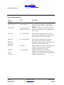
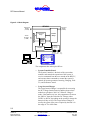
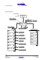
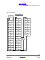
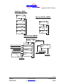
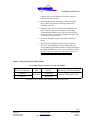
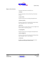
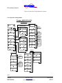
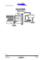
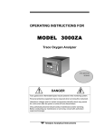
Figure 5-1: Block Diagram shows the components of the RE4500.
5-1
Copyright 2001
Vanner Inc.
4282 Reynolds Dr.
Hilliard Ohio 43026
Phone: (614) 771-271
FAX: 614-771-4904
www.vanner.com
RE Owners_Manual_Rev10d
RE-4500
Installation Manual
Rev 10d
D99988
INCORPORATED
RE Owners Manual
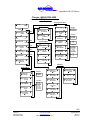
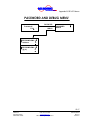
Figure 5-1: Block Diagram
RE-4500
To/From Grid
240 VAC
(or ACM)
To AC Load
240 VAC
(or ACM)
Transfer
Relays
Large Inverter/
Charger
To/From
DC Source
(or DCM)
Small
Inverter/
Charger
Display
On/Off Switch
LEDs, Relays
Controller
Relay A,B,C,D GND
+VDC
Voltage
SETTINGS ALARMS
ADVANCED
HELP
OR
INVERTER/CHARGER
CONTROL
MENU
ESC
ALARM
PC running RE-ICC for Windows
The components that make up the RE are:
•
System Controller Board
The System Controller is the brain of the system that
monitors and controls the operations of the system. It
receives commands from the user entered on the RE-ICC,
and executes those commands to control the system. It
controls all system operations: Inverting, Charging, GridTie, and Generator Control.
•
Large Inverter/Charger
The Large Inverter/Charger is responsible for converting
the DC Voltage from the batteries and the photo-voltaic
modules to split phase, 240 VAC. When in “Charger”
mode, if the batteries are low, this component will convert
the 240VAC from the Grid to the DC Voltage (either
24VDC or 48VDC, depending on the system) to charge the
batteries if they are low. The Large Inverter/Charger is
used by the system if the power required by the load is in
the range of 75 to 4500 watts.
5-2
Copyright 2001
Vanner Inc.
4282 Reynolds Dr.
Hilliard Ohio 43026
Phone: (614) 771-271
FAX: 614-771-4904
www.vanner.com
RE Owners_Manual_Rev10d
RE-4500
Installation Manual
Rev 10d
D99988
INCORPORATED
System Operation Description
•
Small Inverter
This Small Inverter is responsible for converting the
DC Voltage from the batteries and photovoltaic
modules to split phase, 240 VAC. The Small
Inverter/Charger is used by the system if the power
required by the load is from 0 (zero) to 75 watts. The
Small Inverter/Charger is used for improving the
efficiency of the system under light loads.
•
Transfer Relays
The Transfer Relays are responsible for connecting
the:
o
Grid to the Load
o
Small Inverter to the Load
o
Large Inverter to the Load
All of these configurations are under direct control of
the System Controller
•
Display board
The Display board displays system status of the:
o
Inverter
o
Charger
o
Temperature
o
Generator
o
Battery
o
Utility
The Display board also provides relay contacts
(Normally Open, Normally Closed, Common, current
limited VDC (determined by system voltage), and
Ground) for various configured purposes (Generator
Start, Low Battery Warning, etc).
•
Inverter/Charger Control
The Inverter/Charger Controller (RE-ICC/LCD or REICC/VFD) and RE-ICC for Windows provide an
intelligent user interface for configuring, commanding,
and getting status from the RE-4500. The RE-ICC uses
a menu based system for these functions which is
described in the Inverter Charger Controller section on
page 5-13.
5-3
Copyright 2001
Vanner Inc.
4282 Reynolds Dr.
Hilliard Ohio 43026
Phone: (614) 771-271
FAX: 614-771-4904
www.vanner.com
RE Owners_Manual_Rev10d
RE-4500
Installation Manual
Rev 10d
D99988
INCORPORATED
RE Owners Manual
RE_ICC for Windows is a Windows based program
that supports a Windows type Graphical User Interface
for displaying, controlling, configuring, and upgrading
software relating to the operation of the RE-4500. Its’
primary purpose is to assist the installer in the
configuration, field setup and maintenance of the RE4500 system. For more information on RE-ICC for
Windows, please refer to the RE-ICC for Windows
Operations Manual.
5-4
Copyright 2001
Vanner Inc.
4282 Reynolds Dr.
Hilliard Ohio 43026
Phone: (614) 771-271
FAX: 614-771-4904
www.vanner.com
RE Owners_Manual_Rev10d
RE-4500
Installation Manual
Rev 10d
D99988
INCORPORATED
System Operation Description
Modes of Operation
The RE-4500 operates in three modes:
•
Inverting
•
Charging
•
Grid-interactive
This section will describe these and any sub-modes within
them, and their respective faults.
The RE-4500 is designed so that if there is a fault the RE-4500
will shutdown. If the fault condition goes away, the inverter
will restart after 5 minutes in “Auto Recovery” mode.
The next Sections will describe these three modes of operation.
Inverting
When the grid is not available and the batteries have enough
charge then the RE-4500 generates AC power. The 240 VRMS
three-wire output will deliver a continuous 18.75 ARMS @
25°C. Also, if Charging is not enabled and AC Power is
present, then the inverter will run phase-locked to the Grid.
Load Demand (Load Discover)
The inverter does “load demand” to improve efficiency when
the small inverter is not installed and the option is enabled. The
default settings are “Load Demand: ON” and 10 W to enter
load demand (start pulsing) and 75 W to leave load demand
(generate a constant voltage). When the load falls below 10 W
there will be a 5-second delay (default setting) before pulsing
begins.
5-5
Copyright 2001
Vanner Inc.
4282 Reynolds Dr.
Hilliard Ohio 43026
Phone: (614) 771-271
FAX: 614-771-4904
www.vanner.com
RE Owners_Manual_Rev10d
RE-4500
Installation Manual
Rev 10d
D99988
INCORPORATED
RE Owners Manual
Small Inverting
The inverter uses the small inverter when it is installed and the
option is enabled to improve efficiency. The default settings
are “Load Demand: ON” and 10 W to use the small inverter
and 75 W to switch to the large inverter. When the load falls
below 10 W there will be a 5-second delay (default setting)
before switching.
Normal Inverting
“Normal Inverting” is defined as inverting when the load
current is below the maximum (default setting) of 18.75 ARMS.
The inverter generates a constant voltage. 120 VRMS is the
default L1 to Neutral setting. If the current rises above 18.75
ARMS, then the inverter starts surging.
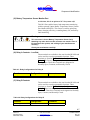
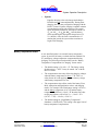
Surging
“Surging” occurs when the load current is above (default
setting) of 18.75 ARMS. For three seconds the inverter attempts
to generate a constant voltage at its default voltage setting. The
inverter will respond and shut down (depending on the load) as
shown in the diagram below.
10
Seconds
56.25 Arms
37.50 Arms
3
Seconds
1 Second
79.55 Arms
Indefinitely
28.13 Arms
18.75 Arms
Chart 5-1: Output Current Surge Fault Response Time @ 25°°C*
.01667
seconds
0.0000514
Seconds
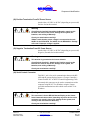
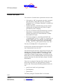
Browning Out
“Brown out” occurs when the load current matches exactly the
(default setting) of 18.75 ARMS. The inverter will supply a
constant current while the output voltage falls. If it falls
5-6
Copyright 2001
Vanner Inc.
4282 Reynolds Dr.
Hilliard Ohio 43026
Phone: (614) 771-271
FAX: 614-771-4904
www.vanner.com
RE Owners_Manual_Rev10d
RE-4500
Installation Manual
Rev 10d
D99988
INCORPORATED
System Operation Description
sufficiently, as shown in the chart below, the inverter will
shutdown.
60 Vrms
420 Vrms
330 Vrms
254 Vrms
120 Vrms
211 Vrms
Chart 5-1: Current Regulation (Brownout) Mode Shutdown Time
Indefinitely
10
Seconds
10
Seconds
.033
Second
.033
Second
.01667
Second
.01667
Second
Low Battery Shutdown
There are two cases that will trigger a low battery shutdown. In
one case, there is no AC present to charge the batteries and in
the other, charging is disabled. When a low battery shutdown
occurs the inverter will not restart until the battery voltage rises
above the Battery shutdown voltage.
The assumption is that there is another source for battery
charging. This avoids cycling the inverter Off and On and
possibly harming the batteries when they are discharged.
5-7
Copyright 2001
Vanner Inc.
4282 Reynolds Dr.
Hilliard Ohio 43026
Phone: (614) 771-271
FAX: 614-771-4904
www.vanner.com
RE Owners_Manual_Rev10d
RE-4500
Installation Manual
Rev 10d
D99988
INCORPORATED
RE Owners Manual
Charging
When the battery voltage falls below the DC Warning level
(default setting / 22 VDC for RE24-4500, 44 VDC for the RE484500), power is taken from the grid and used to fully charge
the batteries starting with Bulk charging. The RE-4500 will
charge the batteries at unity power factor using the full VA
rating of the charger.
The RE-4500 is capable of a maximum charging current of
100ADC.
There are several types of charging modes used by the RE4500 listed below: It should be noted that the numbers for the
below examples are listed for a 24 Volt RE24-4500 with the
numbers for the RE48-4500 in parentheses and Bold italics.
•
Bulk
During Bulk charging the system first presents a
constant DC current to the battery while watching for
the Bulk voltage end limit. The defaults are 100 ADC
and 28.4 VDC respectively (50 ADC and 56.8 VDC for
the RE48). Next, the system holds the battery at the
Bulk voltage 28.4 VDC (56.8 VDC for 48VDC) while
watching for the DC current to drop to the Absorption
current of 10 ADC (56.8 VDC). Then the system does
Absorption charging.
•
Absorption
Absorption charging is a constant current charging
mode with a time out. The system again begins by
directing a constant DC current into the battery (up to
50 ADC (25 ADC)) while watching for the Absorption
voltage limit of 30 VDC (60VDC). If either of these
limits are hit (or 15 minutes passes), then the system
switches to Float charging.
•
Float
Float charging is a constant voltage charging mode
with a current limit. The factory setting is 26.4 VDC
(56.8 VDC ). If the Absorption current limit is hit 50
ADC (25 ADC), then the system resumes Bulk charging.
5-8
Copyright 2001
Vanner Inc.
4282 Reynolds Dr.
Hilliard Ohio 43026
Phone: (614) 771-271
FAX: 614-771-4904
www.vanner.com
RE Owners_Manual_Rev10d
RE-4500
Installation Manual
Rev 10d
D99988
INCORPORATED
System Operation Description
•
Equalize
Equalize charging is the only charge mode that the
RE-4500 does not enter automatically. During Float
charging, the user turns on Equalize charging with the
RE-ICC remote. Equalize charging is another constant
current charging mode with a time out. The system
again directs the constant DC Absorption current (10
ADC for 24VDC, -5 ADC for 48VDC) into the battery
while monitoring the Absorption voltage limit of 31
VDC (62 VDC). Once the limit is encountered or 15
minutes has passed, the system either continues or
begins Float charging.
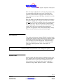
Battery Temperature Sensor
A user-installed option is an external, battery temperature
sensor. It provides for battery overheat detection (default 120
°F), and battery voltage temperature compensation during
charging. The following section describes how the “Battery
Temperature Compensation for Charging” feature works.
•
The default setting is 3.6 mVDC / °C. The factory setting
for this option is “OFF.” It may be turned “On” with the
RE-ICC remote.
•
The compensation value only affects the charging voltages
when the battery temperature is above 77 °F. This is a
safety feature to avoid applying excessive battery voltage
when battery temperatures are low.
•
The compensation value affects each of the battery Float,
Bulk, Absorption and Equalization values, and charging
modes. For example if the Float battery setting is 26.0 VDC,
and the battery temperature is 107 °F, and the battery
temperature coefficient is -10 mV / °F then the float value
used by the software will be 26.0 VDC - {10 mV / °F ×
(107° F - 77 °F) × 12 cells} = 22.4 VDC.
•
The default setting for “High Battery Temperature”
shutdown is 140°F (60°C). This setting is the upper limit of
battery temperature compensation.
5-9
Copyright 2001
Vanner Inc.
4282 Reynolds Dr.
Hilliard Ohio 43026
Phone: (614) 771-271
FAX: 614-771-4904
www.vanner.com
RE Owners_Manual_Rev10d
RE-4500
Installation Manual
Rev 10d
D99988
INCORPORATED
RE Owners Manual
Generator Start Option
This is how the “Generator Start” option for the inverter works:
•
If the option is “ON”, the generator start relay is activated
when the battery voltage falls below the “Low Battery
Threshold” level. “Low Battery Threshold” is settable from
the RE-ICC remote.
•
The RE-4500 looks at the Bulk charge current 4 minutes
(default) after switching on the relay if the AC input is
good and the system is charging.
•
The relay is switched off after the Bulk charge current has
fallen below a current threshold value for 4 minutes
(default). Once again, the “current threshold” is settable
from the RE-ICC remote.
•
The factory settings for “Low battery threshold” and
“current threshold” are 22.5 VDC and 5 ADC respectively for
the RE24-4500 system. For a 48VDC system the factory
settings “Low battery threshold” and “current threshold”
are 44VDC and 2.5 ADC This option is factory set to “ON.”
The relay is used only with a 2-wire generator start.
In order for the Generator Start function to work, the menu
item "Generator Strt" has to be “ON”.
Generator Start (when selected) is triggered by leaving the first
charging stage. The factory setting for the trigger type of the
first charger stage (named "STRT") is "<DC Voltage." This
value's factory setting ("Trigger Setting") is 22.00 Vdc for the
RE24-4500, or 44 Vdc for the RE48-4500. This means that the
generator start relay fires when the battery voltage is less than
this threshold.
There also is a setting for "Generator Wait" which is the time
the inverter waits for the AC input (generator or Grid) to
become valid. This means the following conditions need to be
met:
•
good L1-to-N and L2-to-N grid voltages
•
good frequency
•
phase-locked.
The factory setting for "Generator Wait" is 95 Seconds.
5-10
Copyright 2001
Vanner Inc.
4282 Reynolds Dr.
Hilliard Ohio 43026
Phone: (614) 771-271
FAX: 614-771-4904
www.vanner.com
RE Owners_Manual_Rev10d
RE-4500
Installation Manual
Rev 10d
D99988
INCORPORATED
System Operation Description
If the AC input is still bad after 95 Seconds, the generator relay
is opened and the RE-4500 waits for the "Gen Retry Dly"
period of 5 minutes before trying again. This sequence will
cycle continuously as long as the battery voltage is low and the
grid is bad.
If the AC input is good, then the inverter/charger will progress
through its charging stages using the generator until it reaches
the last one. The factory (or default) setting for charging stages
is 7 so the last one is the 7th. The 7th stage is named "END,"
and is a float setting. When the software reaches this last stage
called "END", the relay is opened thereby stopping the
generator. The generator won't restart until the battery voltage
falls to less than the battery minimum threshold again.
Grid Interactive
This mode provides power from the RE-4500 in parallel with a
second source of power such as the utility or a generator. When
paralleling the utility, the purpose is to sell any excess power
or to limit the peak current consumption. When paralleling a
generator, the purpose is to “stiffen” the AC bus, to provide
peak power that the generator alone is not capable of
providing.
Note:
Strict limits from Sandia National Laboratories are used during Grid
Interactive Mode - Surplus Power. User settings are ignored.
Surplus Power
In this mode the RE-4500 regulates the batteries to their Float
level. Surplus power is directed to the Grid. The implication is
that another source of power such as a Photovoltaic array is
delivering more current into the battery than is required to
maintain a charge. Note: Replaces Vanner’s “Solar Mode.”
5-11
Copyright 2001
Vanner Inc.
4282 Reynolds Dr.
Hilliard Ohio 43026
Phone: (614) 771-271
FAX: 614-771-4904
www.vanner.com
RE Owners_Manual_Rev10d
RE-4500
Installation Manual
Rev 10d
D99988
INCORPORATED
RE Owners Manual
Generator Support
This is an extension of Vanner’s Automatic Power
Management feature. The default setting is 5 ARMS. In this
mode the RE-4500 “backs up” the power source to provide
peak power capability or “load leveling.” This may be to limit
the peak utility power draw or to provide a surge capability
that is greater than the other source can provide on its own. In
this mode the inverter monitors the input RMS current, and
when it exceeds the set value, first, stops consuming power
(charging) and second, begins providing power from the
battery into the load.
Generator Start and GridInteractive
Many generators have poor voltage and frequency regulation.
The RE-4500 can be setup to operate with the wider regulation
that is sometimes required, but only when the inverter is not
connected to the grid. In cases where it is desirable to be
connected to the grid and also have generator backup, the
tighter voltage and frequency settings must be used. These
settings are password protected and can only be set by an
authorized installer.
Set Current
The system controller tells the RE-4500 to supply a constant
RMS current to the Grid. This is done until the battery reaches
its “Low Battery Warning” level, at which point Charging
begins. Charging will continue unless the system controller
changes the setting. The required trip points are used.
5-12
Copyright 2001
Vanner Inc.
4282 Reynolds Dr.
Hilliard Ohio 43026
Phone: (614) 771-271
FAX: 614-771-4904
www.vanner.com
RE Owners_Manual_Rev10d
RE-4500
Installation Manual
Rev 10d
D99988
INCORPORATED
System Operation Description
Bypass
If Charging, Grid-tie, and Inverting are enabled, and if a valid
AC source is present, then the transfer relay will be set after the
generator delay so that AC power flows to the output from the
Grid. If the Grid goes away, Inverting will immediately start.
In this mode, the Inverter acts to backup the utility. User
settings on voltage and frequency are used.
If Charging, Grid-tie, and Inverting are disabled and if a valid
AC source is present, then the transfer relay will be set after the
generator delay so that AC power flows to the output from the
Grid. If the load current goes above the maximum setting, the
relay will open. User settings on voltage, maximum current,
and frequency are used.
System Control
This section describes the Control of the RE-4500. The
controls consist of an On/Off switch and the Inverter/Charger
Controller (RE-ICC).
On/Off Switch
The On/Off switch located on the front panel, turns on and off
the internal logic power supply. This switch also when placed
in the “Off” position resets the system.
Warning
It should be noted that dangerous voltages are still present inside
the RE-4500.
Disconnect all DC and AC Power Sources from the RE-4500 before
attempting any service of the unit.
There are no User Serviceable Components inside the RE-4500!!
5-13
Copyright 2001
Vanner Inc.
4282 Reynolds Dr.
Hilliard Ohio 43026
Phone: (614) 771-271
FAX: 614-771-4904
www.vanner.com
RE Owners_Manual_Rev10d
RE-4500
Installation Manual
Rev 10d
D99988
INCORPORATED
RE Owners Manual
Inverter Charger Control
This section describes the different methods for controlling
and configuring the RE-4500. There are two methods at this
time.
1. Inverter/Charger Controller
2. RE-ICC for Windows
The Inverter/Charger Controller is a handheld remote that
allows field display and configuration of parameters related to
the operation of the RE-4500. The ICC is connected to the
Inverter Serial Control Connector.
RE-ICC for Windows is a Windows based program that
supports a Windows type Graphical User Interface for
displaying, controlling, configuring, and upgrading software
relating to the operation of the RE-4500. Its’ primary purpose
is to assist an installer in the configuration and field setup of
the RE4500. The RE-ICC for Windows operation is not
covered in this document. For more information on RE-ICC
for Windows, please refer to the RE-ICC for Windows
Operations Manual.
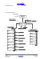
Inverter/Charger Controller
This section describes the operation of the Inverter/Charger
Controller which is shown in Figure 5-1: Inverter/Charger
Controller. The RE-ICC is used to communicate commands
and to monitor the status of the RE-4500. It enables the user to
control the system from a number of menus that control
different aspects of the RE-4500’s operation.
Warning
The Factory Default Settings the unit is shipped with should only be
changed by a Vanner Certified Installer or by Authorized Factory
Personnel. There are no field adjustable Trip Points. All of these
Trip points are password protected to avoid incorrect entries.
Warning
Wrong settings can damage the unit, and lead to personal injury or
death, and voiding of the manufacturers warranty.
5-14
Copyright 2001
Vanner Inc.
4282 Reynolds Dr.
Hilliard Ohio 43026
Phone: (614) 771-271
FAX: 614-771-4904
www.vanner.com
RE Owners_Manual_Rev10d
RE-4500
Installation Manual
Rev 10d
D99988
INCORPORATED
System Operation Description
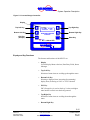
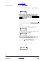
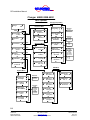
Figure 5-1: Inverter/Charger Controller
Display
Top Left Key
Bottom Left Key
ESC Key
(Escape)
Top Right Key
SETTINGS ALARMS
ADVANCED
HELP
Bottom Right Key
INVERTER/CHARGER
CONTROL
MENU
ESC
Menu Key
ALARM
Alarm LED
Display and Key Functions
The features and functions of the RE-ICC are:
•
Display
Used to display Menu selections, Data Entry Fields, Status
Messages
•
Top Left Key
Selection of menu items or scrolling up through the menu
•
Bottom Left Key
Selecting a displayed item, increasing (Incrementing)
display items, Selecting an “ON” or “YES” function
•
ESC Key
ESC (Escape) key is used to “back up” to the next higher
menu and/or to cancel new data being entered.
•
Top Right Key
Selection of menu items or scrolling down through the
menu
•
Bottom Right Key
5-15
Copyright 2001
Vanner Inc.
4282 Reynolds Dr.
Hilliard Ohio 43026
Phone: (614) 771-271
FAX: 614-771-4904
www.vanner.com
RE Owners_Manual_Rev10d
RE-4500
Installation Manual
Rev 10d
D99988
INCORPORATED
RE Owners Manual
Selecting a displayed item, decreasing (decrementing)
display items, selecting an “OFF” or “NO” function.
•
Menu Key
If a Menu is available for a displayed item, this key when
depressed moves the display to the new menu.
An additional feature of the LCD (Liquid Crystal Display)
version of the RE-ICC is a contrast control. By holding down
the ESC key and pressing either the Top Right Key (to make
the display lighter) or the Bottom Right Key (to make the
display darker), the contrast can be adjusted.
Note:
This adjustment for the contrast only works with the LCD type
display! The VFD (Vacuum Fluorescent Display) is unaffected by
this control.
Moving Around the RE-ICC Menus
First, “Don’t Panic”!
Moving around the Inverter/Charger Controller can be a little
difficult at first, but with a little practice, it will become very
easy! This section contains examples to help the first time user
figure out how to enter data and move around the menus.
WARNING:
This Section contains examples to help the user get started with the RE4500 system. It is assumed that the Inverter has been properly installed at
this point. If the RE-4500 has not been installed, have a qualified (Vanner
Certified) installer perform the installation of the RE-4500 before
proceeding.
Note:
The example settings shown below are for the RE24-4500. The settings for
the RE48-4500 are designated by (Bold Italics in Parentheses)
The RE-ICC Menus consist of the following Menus:
Main Menu
Root Menu, this is the start menu from
which everything can be accessed.
Display Menu
Displays status, voltages, current,
frequency, etc.
5-16
Copyright 2001
Vanner Inc.
4282 Reynolds Dr.
Hilliard Ohio 43026
Phone: (614) 771-271
FAX: 614-771-4904
www.vanner.com
RE Owners_Manual_Rev10d
RE-4500
Installation Manual
Rev 10d
D99988
INCORPORATED
System Operation Description
Settings Menu
Turns Options On / Off and adjusts
functional parameters for the RE-4500–
mostly used for installation.
Advanced Menu
Adjusts more advanced features dealing
with communication, calibration,
debugging, in addition to providing
password protection levels.
Help Menu
Gives Version level, Help, and Index
menus.
Alarm Menu
Displays status messages and
automatically scrolls through the listing
of active alarms. See Appendix B: REICC Menus.
Turning The Inverter / Charger On and Off
The first procedure we will do is to walk you through the
startup of the Inverter/Charger.
Note:
The Up and Down arrows are actually meant to mean any of the 4
upper buttons on the RE-ICC.
1. First press ESC. The Display will change to
SETTINGS ALARMS
ADVANCED
HELP
2. Press the Top Left Key (Next to SETTINGS). The Display
will change to
Inverter
on
OFF
3. Press the Lower Left Key. This will turn the Inverter On.
The Display will change to
Inverter
ON
off
4. Press the Lower Right Key (this will turn the Inverter Off).
The Display will change to
Inverter
on
OFF
5-17
Copyright 2001
Vanner Inc.
4282 Reynolds Dr.
Hilliard Ohio 43026
Phone: (614) 771-271
FAX: 614-771-4904
www.vanner.com
RE Owners_Manual_Rev10d
RE-4500
Installation Manual
Rev 10d
D99988
INCORPORATED
RE Owners Manual
CONGRATULATIONS!! You have turned the Inverter on and
off with the RE-ICC!
Next, we will acquaint you with the Menus!
Menu Functions
This section will describe the operation of moving around the
Menus of the RE-ICC.
See Figure 5-1: RE-ICC Menus. This is a layout of the RE-ICC
Menus. You will see that you have already moved into a sub
menu by getting to the Inverter Control Screen!
This section will help you navigate through the different menus
associated with the RE-4500.
Don’t Worry! You can Escape to where you came from by
simply pressing ESC.
5-18
Copyright 2001
Vanner Inc.
4282 Reynolds Dr.
Hilliard Ohio 43026
Phone: (614) 771-271
FAX: 614-771-4904
www.vanner.com
RE Owners_Manual_Rev10d
RE-4500
Installation Manual
Rev 10d
D99988
INCORPORATED
System Operation Description
Figure 5-1: RE-ICC Menus
MENU
ESC
SETTINGS
ALARMS
Settings Menu
Alarms Listing
ESC
Advanced Menu
Inverter Menu
ESC
HELP
ESC
ESC
ADVANCED
Display Menu
Help Menu
Remote Settings Menu
Surge Menu
Voltage Limits Menu
Communications Menu
Small Inverter Menu
Calibration Menu
About Menu
Contents Menu
Index Menu
(TBD)
(TBD)
Customization Menu
Fan Menu
Charger Menu
Charge Stages Menu
Generator Menu
Equalization Menu
Password Menu
Debug Menu
Grid Interact Menu
Grid Frequency Menu
Grid Voltage Menu
Note: Most of the submenus are arrived at
by pressing the "Menu" key while
displaying an "ON off" display screen.
Battery Menu
Battery Temp. Menu
Miscellaneous Menu
Auto Restart Menu
Inverter Communications Menu
For more information, please see the
appropriate Menu diagram.
Stacking Menu
Time and Date Menu
5-19
Copyright 2001
Vanner Inc.
4282 Reynolds Dr.
Hilliard Ohio 43026
Phone: (614) 771-271
FAX: 614-771-4904
www.vanner.com
RE Owners_Manual_Rev10d
RE-4500
Installation Manual
Rev 10d
D99988
INCORPORATED
RE Owners Manual
Figure 5-2: Main Menu
Startup Display
TurboRemote
XA88974-A
2 seconds
Main Menu
MENU
ESC
SETTINGS
Settings Menu
Display Menu
SETTINGS ALARMS
ADVANCED
HELP
To HELP MENU
To ADVANCED Root MENU
Example Alarm List
Depends on number of Alarms
Inverter
ON
off
Charger
on
OFF
Menu
Grid Interact
on
OFF
Menu
Battery
on
OFF
Menu
Miscellaneous
Stacking
on
Menu
Menu
To INVERTER MENU
To CHARGER MENU
To Grid Interact MENU
To Battery MENU
To Miscellaneous MENU
OFF
Menu
To Stacking MENU
Time and Date
on
OFF
Menu
To Time and Date MENU
ALARMS:
BATTERY LOW
ALARMS:
BATT. TOO LOW
ALARMS:
BAD GRID FREQ.
ALARMS:
NO PHASE LOCK
5-20
Copyright 2001
Vanner Inc.
4282 Reynolds Dr.
Hilliard Ohio 43026
Phone: (614) 771-271
FAX: 614-771-4904
www.vanner.com
RE Owners_Manual_Rev10d
RE-4500
Installation Manual
Rev 10d
D99988
INCORPORATED
System Operation Description
Figure 5-3: Inverter Menu
INVERTER MENUS
Inverter
on
INVERTER MENU
ON
Small
Inverter
off
Small
YES
Inverter
no
OFF
MENU
MENU
VOLTAGE Limits MENU
+
+
Inv. Output
240. 0 Vrms Max Inv. Currnt
18.7 5 Arms -
Small Inverter MENU
+
Small Inv Strt
7 5 Watts
-
+
Small Inv Stop
8 0 Watts
-
+
Small Inv Tail
5 Seconds
+
Small Inv Ramp
4 Cycles
-
+
Small Inv Delta
1 Seconds
-
MENU
SURGE MENU
Upper Volts #1
+
264. 0 Vrms -
MENU
+
+
+
Max Inv. Srge 1
28.1 3 Arms -
Max Inv. Srge 2
37.5 0 Arms -
Max Inv. Srge 3
56.2 5 Arms -
Inv Limit Dly
+
600 Cycles
Inv Srge Dly 3
+
1 Cycles
+
Upper Volts #2
328. 0 Vrms -
+
Lower Volts #2
119. 8 Vrms -
+
Upper Volts #3
420. 0 Vrms -
+
Lower Volts #3
59. 8 Vrms -
+
Volt Lmt Dly 1
600 Cycles -
+
Volt Lmt Dly 2
120 Cycles -
+
Volt Lmt Dly 3
2 Cycles -
-
-
Inv Srge Dly 1
+
180 Cycles
Inv Srge Dly 2
+
60 Cycles
Lower Volts #1
+
211. 8 Vrms -
-
-
-
Leave Srge Dly
+
1 Cycles -
5-21
Copyright 2001
Vanner Inc.
4282 Reynolds Dr.
Hilliard Ohio 43026
Phone: (614) 771-271
FAX: 614-771-4904
www.vanner.com
RE Owners_Manual_Rev10d
RE-4500
Installation Manual
Rev 10d
D99988
INCORPORATED
RE Owners Manual
1. Press the Top Right Key next to the ↓ symbol. This will
move you to the next menu item. The Display will change
to
Charger
on
OFF
2. Keep pressing the Top Right Key next to the ↓ symbol.
You will see that each time you press the key that the
screen will advance down the list in Figure 5-1: RE-ICC
Menus. If you hold the ↓ key down the menu items will
scroll DOWN rapidly.
3. Try pressing the Top Left Key next to the ↑ symbol. You
will find that the each time you press the key that the
screen will advance up the list in Figure 5-2: Main Menu.
If you hold the ↑ key down the menu items will scroll UP
rapidly.
You will also notice that this menu “wraps around”. In
other words, when you reach the bottom of the list
Time and Date
on
OFF
the next screen to show up will be the “Inverter on / OFF”
screen, bringing you back to the top.
Inverter
on
OFF
Likewise the same thing happens with the ↑ arrow. The
Menu will wrap around with the next item above the
Inverter screen being the Time and Date screen.
As you look at Figure 5-1: RE-ICC Menus, you will notice
that the many of the screens have additional menus that can
be accessed from them.
If you are not at the “Inverter on OFF” screen, go to it now
and press the “MENU” button. You will now be at a new
screen
Small
ON
Inverter
off
5-22
Copyright 2001
Vanner Inc.
4282 Reynolds Dr.
Hilliard Ohio 43026
Phone: (614) 771-271
FAX: 614-771-4904
www.vanner.com
RE Owners_Manual_Rev10d
RE-4500
Installation Manual
Rev 10d
D99988
INCORPORATED
System Operation Description
You are now at the first item in the INVERTER Menu.
The Inverter Menu structure is shown in Figure 5-3:
Inverter Menu.
As you can see, you have options of where to go from
here!
4. Press the ESC key. This will take you back to the
SETTINGS Menu. The Display should look like the
following:
Inverter
on
OFF
5. Press the ESC key again. This will take you back to the
Main screen shown below:
SETTINGS ALARMS
ADVANCED
HELP
This returns you to the Main Menu.
Congratulations! You now know how to navigate the
menus!
Note:
In order to prevent settings that might cause damage to personnel, or
property, the RE-4500 has been equipped with password protection
to avoid any wrong entry of data.
The RE-4500 is shipped with the following configuration:
•
User – (7734) This level of access allows viewing of all
the menu items and some limited adjustment of
parameters, but no adjustment to the more advanced
parameters. Changes are limited to the “Settings” Menu.
For further information on menu items please refer to
Appendix B: RE-ICC Menus. This section has the complete
menu structure for the RE-ICC.
Warning
Changes to the menu items at any level but the user should only be
done by Vanner Authorized personnel. Failure to follow proper
procedures and configurations can lead to death, explosion,
electrocution, loss of property and equipment, and voiding of
warranty!
5-23
Copyright 2001
Vanner Inc.
4282 Reynolds Dr.
Hilliard Ohio 43026
Phone: (614) 771-271
FAX: 614-771-4904
www.vanner.com
RE Owners_Manual_Rev10d
RE-4500
Installation Manual
Rev 10d
D99988
INCORPORATED
RE Owners Manual
Display Menu
This Menu is accessed by pressing the “Menu” button when at
the Main Menu. This will bring up the menu show in Figure
5-1: Display Menu. This menu can be used to display status of
voltages, currents, power, temperature, or many other
monitored status items associated with the RE-4500. The
“ESC” key will take you back to the Main menu.
5-24
Copyright 2001
Vanner Inc.
4282 Reynolds Dr.
Hilliard Ohio 43026
Phone: (614) 771-271
FAX: 614-771-4904
www.vanner.com
RE Owners_Manual_Rev10d
RE-4500
Installation Manual
Rev 10d
D99988
INCORPORATED
System Operation Description
Figure 5-1: Display Menu
Display Menu
INV L1 VLT-AMP
2555 VA
GRID L2-to-N
119.8 Vrms
INVERTER TIME
10:10:31
INV L1 PWR-FCT
88%
GRD L2 CURRENT
18.70 Arms
INVERTER DATE
1/ 1/ 0
INVRTR L2-to-N
119.8 Vrms
GRID L2 POWER
-2250 Watts
INV L2 CURRENT
18.70 Arms
GRD L2 VLT-AMP
2240 VA
BATTERY STATUS
LOW - OFF
INVRTR L2 POWR
-2250 Watts
GRD L2 PWR-FCT
-99%
BATTERY VOLTS
13.27 Vdc
INV L2 VLT-AMP
2240 VA
GRID FREQUENCY
60.00 Hz
BATTERY PWR
0 Watts
INV L2 PWR-FCT
-99%
PLL LOCK ERROR
0.30 °
BATTERY CURRNT
0.0 Adc
LOAD FREQUENCY
60.00 Hz
GRID L1-to-L2
236.1 Vrms
BATTERY TEMP.
0.0 °C
GRID STATUS
PHASELOCKED!
BATT TEMP COMP
0.00 Vdc
GRID L1-to-N
118.5 Vrms
SYSTEM TEMP.
25.8 °C
GRD L1 CURRENT
18.70 Arms
INVRTR L1-to-N
137.0 Vrms
GRID L1 POWER
-2250 Watts
INV L1 CURRENT
18.65 Arms
GRD L1 VLT-AMP
2216 VA
INVRTR L1 POWR
2249 Watts
GRD L1 PWR-FCT
99 %
ESC
MENU
SETTINGS ALARMS
ADVANCED
HELP
INVERTER
FAULTED-
L1-to-N GOOD
L2-to-N GOOD
GRID FREQ GOOD
L1&L2 MISMATCH
PHASELOCKED!
5-25
Copyright 2001
Vanner Inc.
4282 Reynolds Dr.
Hilliard Ohio 43026
Phone: (614) 771-271
FAX: 614-771-4904
www.vanner.com
RE Owners_Manual_Rev10d
RE-4500
Installation Manual
Rev 10d
D99988
INCORPORATED
Preventive Maintenance and
Trouble Shooting Procedures
6
Preventive Maintenance and
Trouble Shooting Procedures
There are no user serviceable components inside the inverter. If
the inverter requires service, refer to the Vanner Incorporated
or other qualified service personnel.
Preventive Maintenance
For continued reliability and safety, a monthly maintenance
program should be implemented to include the following:
1. Check to insure that all wiring connections are tight, secure
and corrosion free.
2. Check fan exhaust and intake vents for obstructions.
3. Examine connectors, indicators and switches for cracks
and breaks.
4. Examine any surfaces that are discolored or deformed due
to excessive heat.
Trouble Shooting
Procedures
The following are the most common questions heard by
Vanner service professionals. If your situation does not apply
to the following categories, please contact your local Vanner
Inc. Service Center or the Vanner Inc. Customer Service
Department: 1-800-AC-POWER (1-800-227-6937). Please
have your model and serial number available when consulting
customer service.
6-1
Copyright 2001
Vanner Inc.
4282 Reynolds Dr.
Hilliard Ohio 43026
Phone: (614) 771-271
FAX: 614-771-4904
www.vanner.com
RE Owners_Manual_Rev10d
RE-4500
Installation Manual
Rev 10d
D99988
INCORPORATED
RE Owners Manual
Preliminary Checks
1. Indicator Light status
2. Inverter ON/OFF Switch position.
3. Battery voltage at battery and battery voltage at the
inverter terminals. Voltage present at inverter/charger does
not prove that all connections are sound especially under
no AC load. (see item 7)
4. DC Fuse condition
5. DC Disconnects condition
6. Battery connections for tightness or corrosion
6-2
Copyright 2001
Vanner Inc.
4282 Reynolds Dr.
Hilliard Ohio 43026
Phone: (614) 771-271
FAX: 614-771-4904
www.vanner.com
RE Owners_Manual_Rev10d
RE-4500
Installation Manual
Rev 10d
D99988
INCORPORATED
Preventive Maintenance and
Trouble Shooting Procedures
Problem Symptoms and
Troubleshooting Checks
If you have this problem:
Inverter Indicator Light does not turn ON.
Inverter Indicator Light is ON but the AC load
will not operate.
Low Battery Indicator Light is ON when AC
load is applied.
Over Temperature Indicator Light is RED.
Inverter Light Turns RED when AC load is
applied.
DC fuse blows when connecting DC input
cables.
Excessive audible buzzing during inverter
operation but inverter operates loads.
AC loads do not seem to be fully energized
when operating from inverter power.
Unit does not operate and a “burnt wire” smell
emits from inverter/charger.
Do this:
Verify DC voltage at the inverter.
Check and reset GFCI receptacle or circuit
breakers. Verify AC wiring. Try a different load
such as a trouble light.
Check battery connections and condition.
Recharge battery if voltage is less than 22.0
VDC. Low battery warning is 22 VDC and
Inverter Shutdown is 21 VDC (44VDC and
42VDC for the RE48-4500).
Check to see if Charger is enabled in RE-ICC
Settings Menu. Check alarm status on Charger.
Verify fan operation. Remove obstructions from
air intake vents and exhaust fan.
Verify AC load is within the inverter’s rated
capacity. Remove excessive loads.
Check for reverse polarity (Positive and
negative DC cables reversed.)
Check mounting bracket bolt tightness.
Check AC output voltage at AC Output
Terminals. Check for overheated DC or AC
wiring. Verify AC load specifications are not
exceeded.
Disconnect AC loads and DC Source
immediately. Unit may require service, contact
Vanner service department.
6-3
Copyright 2001
Vanner Inc.
4282 Reynolds Dr.
Hilliard Ohio 43026
Phone: (614) 771-271
FAX: 614-771-4904
www.vanner.com
RE Owners_Manual_Rev10d
RE-4500
Installation Manual
Rev 10d
D99988
INCORPORATED
Appendix A: Warranty
Appendix A: Warranty
NORTH AMERICAN LIMITED WARRANTY
Vanner Inc., doing business as The Vanner Inc., referred to herein as Vanner, warrants that this
product is free from defects in materials and workmanship for a period of two (2) years from date of
installation or two and one half (2 1/2) years from date of manufacture, whichever is less if and only
if the following requirements are complied with:
1. The product is installed and checked out properly according to all guidelines, instructions,
and checkout procedures set forth in the product Installation and Operating Manual.
2. The installer records all checkout data required and completes, signs, and returns the warranty
registration card to Vanner within ten (10) days after installation.
3. The product was purchased after January 1, 2000.
Vanner does not warrant its products against any and all defects when: defect is a result of material or
workmanship not provided by Vanner; normal wear and tear, or defects caused by misuse or use in
contrary to instructions supplied, neglect, accident, reversed polarity, unauthorized repairs and/or
replacements.
Vanner does not manufacture this product for use in a life supporting or life sustaining role. Please
contact Vanner if you have any questions along this line.
All warranties of merchantability and fitness for a particular purpose: written or oral, expressed or
implied, shall extend only for a period of two (2) years from date of installation or two and one half (2
1/2) years from date of manufacture, whichever is first. There are no other warranties that extend
beyond those described on the face of this warranty. Some states do not allow limitation on how long
an implied warranty lasts, so the above limitations may not apply to you.
Vanner does not undertake responsibility to any purchaser of its product for any undertaking,
representation, or warranty made by any dealers or distributors selling its products beyond those
herein expressed unless expressed in writing by an officer of Vanner.
Vanner does not assume responsibility for incidental or consequential damages, including, but not
limited to, responsibility for loss of use of this product, removal or replacement labor, loss of time,
inconvenience, expense for telephone calls, shipping expense, loss or damage to property, or loss of
revenue. Some states do not allow the exclusion or limitation of incidental or consequential damages,
so these limitations may not apply to you.
A-1
Copyright 2001
Vanner Inc.
4282 Reynolds Dr.
Hilliard Ohio 43026
Phone: (614) 771-271
FAX: 614-771-4904
www.vanner.com
RE Owners_Manual_Rev10d
RE-4500
Installation Manual
Rev 10d
D99988
INCORPORATED
RE Owners Manual
Vanner reserves the right to repair, replace, or allow credit for any material returned under this
warranty. Any damage caused by the customer will be charged or deducted from the allowance.
All warranty work will be performed at Vanner’s factory, by authorized Vanner distributors, by
Vanner installers/technicians, or a Vanner authorized repair facility utilizing a valid Warranty
Authorization Number (WAN) prior to repair. Products shall be delivered to Vanner’s facility, freight
prepaid and fully insured. Products repaired under warranty, or replacement parts or products will be
returned to North American location prepaid via same transportation means and level of service as
received, unless directed otherwise. Prepaid freight policy does not apply to locations outside North
America.
A-2
Copyright 2001
Vanner Inc.
4282 Reynolds Dr.
Hilliard Ohio 43026
Phone: (614) 771-271
FAX: 614-771-4904
www.vanner.com
RE Owners_Manual_Rev10d
RE-4500
Installation Manual
Rev 10d
D99988
INCORPORATED
Appendix B: RE-ICC Menus
Appendix B: RE-ICC Menus
MENU
ESC
SETTINGS
ALARMS
Settings Menu
Alarms Listing
ESC
Advanced Menu
Inverter Menu
ESC
HELP
ESC
ESC
ADVANCED
Display Menu
Help Menu
Remote Settings Menu
Surge Menu
Voltage Limits Menu
Communications Menu
Small Inverter Menu
Calibration Menu
About Menu
Contents Menu
Index Menu
(TBD)
(TBD)
Customization Menu
Fan Menu
Charger Menu
Charge Stages Menu
Generator Menu
Equalization Menu
Password Menu
Debug Menu
Grid Interact Menu
Grid Frequency Menu
Grid Voltage Menu
Note: Most of the submenus are arrived at
by pressing the "Menu" key while
displaying an "ON off" display screen.
Battery Menu
Battery Temp. Menu
Miscellaneous Menu
Auto Restart Menu
Inverter Communications Menu
For more information, please see the
appropriate Menu diagram.
Stacking Menu
Time and Date Menu
B-1
Copyright 2001
Vanner Inc.
4282 Reynolds Dr.
Hilliard Ohio 43026
Phone: (614) 771-271
FAX: 614-771-4904
www.vanner.com
RE Owners_Manual_Rev10d
RE-4500
Installation Manual
Rev 10d
D99988
INCORPORATED
RE Owners Manual
Startup Display
TurboRemote
XA88974-A
2 seconds
Main Menu
MENU
ESC
SETTINGS
Settings Menu
Display Menu
SETTINGS ALARMS
ADVANCED
HELP
To HELP MENU
To ADVANCED Root MENU
Example Alarm List
Depends on number of Alarms
Inverter
ON
off
Charger
on
OFF
Grid Interact
on
OFF
Menu
Battery
on
OFF
Menu
Miscellaneous
Stacking
on
Menu
Menu
Menu
To INVERTER MENU
To CHARGER MENU
To Grid Interact MENU
To Battery MENU
To Miscellaneous MENU
OFF
Menu
To Stacking MENU
Time and Date
on
OFF
Menu
To Time and Date MENU
ALARMS:
BATTERY LOW
ALARMS:
BATT. TOO LOW
ALARMS:
BAD GRID FREQ.
ALARMS:
NO PHASE LOCK
B-2
Copyright 2001
Vanner Inc.
4282 Reynolds Dr.
Hilliard Ohio 43026
Phone: (614) 771-271
FAX: 614-771-4904
www.vanner.com
RE Owners_Manual_Rev10d
RE-4500
Installation Manual
Rev 10d
D99988
INCORPORATED
Appendix B: RE-ICC Menus
Display Menu
INV L1 VLT-AMP
2555 VA
GRID L2-to-N
119.8 Vrms
INVERTER TIME
10:10:31
INV L1 PWR-FCT
88%
GRD L2 CURRENT
18.70 Arms
INVERTER DATE
1/ 1/ 0
INVRTR L2-to-N
119.8 Vrms
GRID L2 POWER
-2250 Watts
INV L2 CURRENT
18.70 Arms
GRD L2 VLT-AMP
2240 VA
BATTERY STATUS
LOW - OFF
INVRTR L2 POWR
-2250 Watts
GRD L2 PWR-FCT
-99%
BATTERY VOLTS
13.27 Vdc
INV L2 VLT-AMP
2240 VA
GRID FREQUENCY
60.00 Hz
BATTERY PWR
0 Watts
INV L2 PWR-FCT
-99%
PLL LOCK ERROR
0.30 °
BATTERY CURRNT
0.0 Adc
LOAD FREQUENCY
60.00 Hz
GRID L1-to-L2
236.1 Vrms
BATTERY TEMP.
0.0 °C
GRID STATUS
PHASELOCKED!
BATT TEMP COMP
0.00 Vdc
GRID L1-to-N
118.5 Vrms
SYSTEM TEMP.
25.8 °C
GRD L1 CURRENT
18.70 Arms
INVRTR L1-to-N
137.0 Vrms
GRID L1 POWER
-2250 Watts
INV L1 CURRENT
18.65 Arms
GRD L1 VLT-AMP
2216 VA
INVRTR L1 POWR
2249 Watts
GRD L1 PWR-FCT
99 %
ESC
MENU
SETTINGS ALARMS
ADVANCED
HELP
INVERTER
FAULTED-
L1-to-N GOOD
L2-to-N GOOD
GRID FREQ GOOD
L1&L2 MISMATCH
PHASELOCKED!
B-3
Copyright 2001
Vanner Inc.
4282 Reynolds Dr.
Hilliard Ohio 43026
Phone: (614) 771-271
FAX: 614-771-4904
www.vanner.com
RE Owners_Manual_Rev10d
RE-4500
Installation Manual
Rev 10d
D99988
INCORPORATED
RE Owners Manual
INVERTER MENUS
Inverter
on
INVERTER MENU
ON
Small
Inverter
off
Small
YES
Inverter
no
OFF
MENU
MENU
VOLTAGE Limits MENU
+
+
Inv. Output
240.0 Vrms Max Inv. Currnt
18.75 Arms -
Small Inverter MENU
+
Small Inv Strt
75 Watts
-
+
Small Inv Stop
80 Watts
-
+
Small Inv Tail
5 Seconds
-
+
Small Inv Ramp
4 Cycles
-
+
Small Inv Delta
1 Seconds -
MENU
SURGE MENU
Upper Volts #1
+
264.0 Vrms -
MENU
+
Max Inv. Srge 1
28.13 Arms -
Max Inv. Srge 2
+
37.50 Arms -
Lower Volts #1
+
211.8 Vrms -
+
Upper Volts #2
328.0 Vrms -
Max Inv. Srge 3
+
56.25 Arms -
+
Lower Volts #2
119.8 Vrms -
Inv Limit Dly
+
600 Cycles
+
Upper Volts #3
420.0 Vrms -
+
Lower Volts #3
59.8 Vrms -
+
Volt Lmt Dly 1
600 Cycles -
+
Volt Lmt Dly 2
120 Cycles -
+
Volt Lmt Dly 3
2 Cycles -
-
Inv Srge Dly 1
+
180 Cycles
Inv Srge Dly 2
+
60 Cycles
Inv Srge Dly 3
+
1 Cycles
-
-
-
Leave Srge Dly
+
1 Cycles -
B-4
Copyright 2001
Vanner Inc.
4282 Reynolds Dr.
Hilliard Ohio 43026
Phone: (614) 771-271
FAX: 614-771-4904
www.vanner.com
RE Owners_Manual_Rev10d
RE-4500
Installation Manual
Rev 10d
D99988
INCORPORATED
Appendix B: RE-ICC Menus
Charger MENU RE24-4500
24V System
Charging Steps Menu
Charger
on
Generator Menu
OFF
+
MENU
MENU
Charging Steps
+
7 Steps
Relay Board
YES
Generator Strt
ON
Equalize Mode
yes
+
Soft Start Rmp
10 Seconds
Generator Wait
95 Seconds-
+
Gen Retry Dly
5 Minutes-
no
MENU
Grid Good Menu
off
MENU
DC POWER
DC CURRENT
DC VOLTAGE
Chrg Stg Type
DC Current
Chrg Stg Sttng
+
0.0Adc
-
+
+
Lower Freq #1
55.00 Hz -
Trigger Settng
+
22.0 0 Vdc
NO
+
Upper Freq #2
70.0 0 Hz -
Chrg Stg Tmout
+
0.00 Hours -
-
+
Lower Freq #2
40.0 0 Hz -
MENU
Watts
Adc
Vdc
Selections
Trigger Type
<DC VOLTAGE
-
1 through 8
Selections
Upper Freq #1
65.0 0 Hz -
MENU
Selections
Chrge Stg Name
STRT
-
Grid Good Delay
+
90 Secs
APM Limit
+
30.00 Arms
+
Charge Stage #
1 -
-
SPARE
<DC POWER
<DC CURRENT
<DC VOLTAGE
SPARE
>DC POWER
>DC CURRENT
>DC VOLTAGE
Watts
Adc
Vdc
APM Menu
Equalize Menu
Selections
Equalize Type
DC Voltage
+
Equal. Setting
31.0 0dc
+
Equal. Timeout
0.25 Hours
+
APM Srge Dly 3
1 Cycles -
+
Max APM Srge 2
99.9 9 Arms -
+
APM Derate St
50.0 ° C -
+
Max APM Srge 3
99.9 9 Arms -
+
APM Tmp Derate
-250.0 mA/°C -
+
APM Limit Dly
600 cycles -
+
APM Srge Dly 1
180 Cycles -
+
APM Srge Dly 2
60 Cycles -
-
Equl End Type
<DC CURRENT
Equl End Set'g
10.0dc
Max APM Srge 1
60.0 0 Arms -
DC POWER
DC CURRENT
DC VOLTAGE
Selections
+
+
-
SPARE
<DC POWER
<DC CURRENT
<DC VOLTAGE
SPARE
>DC POWER
>DC CURRENT
>DC VOLTAGE
-
B-5
Copyright 2001
Vanner Inc.
4282 Reynolds Dr.
Hilliard Ohio 43026
Phone: (614) 771-271
FAX: 614-771-4904
www.vanner.com
RE Owners_Manual_Rev10d
RE-4500
Installation Manual
Rev 10d
D99988
INCORPORATED
RE Owners Manual
Charger MENU RE48-4500
48V System
Charging Steps Menu
Charger
on
Generator Menu
OFF
+
MENU
MENU
Charging Steps
+
7 Steps
no
Generator Strt
ON
off
Equalize Mode
yes
+
Soft Start Rmp
1 0 Seconds
+
Gen Retry Dly
5 Minutes-
MENU
DC POWER
DC CURRENT
DC VOLTAGE
Chrg Stg Type
DC Current
Chrg Stg Sttng
+
0.0Adc
-
+
+
Lower Freq #1
55.00 Hz -
Trigger Settng
+
44.0 0 Vdc
NO
+
Upper Freq #2
70.0 0 Hz -
Chrg Stg Tmout
+
0.0 0 Hours -
-
+
Lower Freq #2
40.0 0 Hz -
MENU
Watts
Adc
Vdc
Selections
Trigger Type
<DC VOLTAGE
MENU
1 through 8
Selections
Upper Freq #1
65.0 0 Hz -
-
Selections
Chrge Stg Name
STRT
Grid Good Menu
MENU
Grid Good Delay
+
90 Secs
APM Limit
30.0 0 Arms
Generator Wait
9 5 Seconds-
-
Relay Board
YES
+
+
Charge Stage #
1 -
-
SPARE
<DC POWER
<DC CURRENT
<DC VOLTAGE
SPARE
>DC POWER
>DC CURRENT
>DC VOLTAGE
Watts
Adc
Vdc
APM Menu
Equalize Menu
Selections
Equalize Type
DC Voltage
+
Equal. Setting
62.0 0dc
SPARE
<DC POWER
<DC CURRENT
<DC VOLTAGE
SPARE
>DC POWER
>DC CURRENT
>DC VOLTAGE
Equl End Set'g
5. 0dc
Equal. Timeout
0.2 5 Hours
+
APM Srge Dly 3
1 Cycles -
+
Max APM Srge 2
99.9 9 Arms -
+
APM Derate St
50.0 ° C -
+
Max APM Srge 3
99.9 9 Arms -
+
APM Tmp Derate
-250.0 mA/°C -
+
APM Limit Dly
600 cycles -
+
APM Srge Dly 1
18 0 Cycles -
+
APM Srge Dly 2
6 0 Cycles -
-
Equl End Type
<DC CURRENT
+
Max APM Srge 1
60.0 0 Arms -
DC POWER
DC CURRENT
DC VOLTAGE
Selections
+
+
-
B-6
Copyright 2001
Vanner Inc.
4282 Reynolds Dr.
Hilliard Ohio 43026
Phone: (614) 771-271
FAX: 614-771-4904
www.vanner.com
RE Owners_Manual_Rev10d
RE-4500
Installation Manual
Rev 10d
D99988
INCORPORATED
Appendix B: RE-ICC Menus
Grid Interact Menus
Grid Interact
on
OFF
MENU
+
Load Support
10.00 Arms
-
Grid Frq Sttngs
Grid Vlt Sttngs
Grid Freq. MENU
MENU
Grid Voltage MENU
MENU
+
UL 1741 Delay
301 Secs
-
+
Upper Freq #1
60.2 5 Hz -
+
Upper Volts #1
264. 0 Vrms -
+
Lower Freq #1
59.7 5 Hz -
+
Lower Volts #1
211. 8 Vrms -
+
Upper Freq #2
60.5 0 Hz -
+
Upper Volts #2
328. 0 Vrms -
+
Lower Freq #2
59.3 0 Hz -
+
Lower Volts #2
119. 8 Vrms -
+
Freq Bad Dly 1
5 Cycles -
+
Upper Volts #3
420. 0 Vrms -
+
Freq Bad Dly 2
1 Cycles -
+
Lower Volts #3
59. 8 Vrms -
+
Freq Good Dly
1 Cycles -
+
AC Bad Delay 1
115 Cycles -
+
AC Bad Delay 2
0 Cycles
-
+
AC Bad Delay 3
0 Cycles
-
+
AC Good Delay
60 Cycles -
B-7
Copyright 2001
Vanner Inc.
4282 Reynolds Dr.
Hilliard Ohio 43026
Phone: (614) 771-271
FAX: 614-771-4904
www.vanner.com
RE Owners_Manual_Rev10d
RE-4500
Installation Manual
Rev 10d
D99988
INCORPORATED
RE Owners Manual
Battery MENU RE24-4500
24 Volt System
Battery
MENU
+
Low Batt Warn.
22.00 Vdc
-
+
LowBat ShutDn
21.00 Vdc
-
+
HighBat Shutdn
31.00 Vdc
-
Battery Temp. Menu
Batt Temp Comp
on
OFF
MENU
+
Batt Bad Delay
13 Secs -
+
High Batt Shut
60.0 ° C
-
+
Batt Good Delay
1 Secs -
+
Low Batt Shut
0.0°C
-
+
Batt Temp Strt
25.0°C
-
+
Batt Temp Coef
-5.00mV/°C/Cl # of Cells
+
12 -
B-8
Copyright 2001
Vanner Inc.
4282 Reynolds Dr.
Hilliard Ohio 43026
Phone: (614) 771-271
FAX: 614-771-4904
www.vanner.com
RE Owners_Manual_Rev10d
RE-4500
Installation Manual
Rev 10d
D99988
INCORPORATED
Appendix B: RE-ICC Menus
Battery MENU RE48-4500
48 Volt System
Battery
MENU
+
Low Batt Warn.
44.00 Vdc
-
+
LowBat ShutDn
42.00 Vdc
-
+
HighBat Shutdn
61.00 Vdc
-
Battery Temp. Menu
Batt Temp Comp
on
OFF
MENU
+
Batt Bad Delay
13 Secs -
+
High Batt Shut
60.0 ° C
-
+
Batt Good Delay
1 Secs -
+
Low Batt Shut
0.0°C
-
+
Batt Temp Strt
25.0°C
-
+
Batt Temp Coef
-5.00mV/°C/Cl # of Cells
+
12 -
B-9
Copyright 2001
Vanner Inc.
4282 Reynolds Dr.
Hilliard Ohio 43026
Phone: (614) 771-271
FAX: 614-771-4904
www.vanner.com
RE Owners_Manual_Rev10d
RE-4500
Installation Manual
Rev 10d
D99988
INCORPORATED
RE Owners Manual
Miscellaneous MENU
Miscellaneous
MENU
Auto Restart
ON
off
MENU
Output Feedbck
ON
off
+
+
Auto Restart
5 Mins
-
Shutdown Temp.
70. 0 °C
-
Display Board
YES
no
Reset EEPROM
yes
NO
Inverter
Communications
MENU
Inverter Addr.
+
1-
+
Xmit Timeout
1 Secs -
+
Recv Timeout
0 Secs Retries
+
5-
B-10
Copyright 2001
Vanner Inc.
4282 Reynolds Dr.
Hilliard Ohio 43026
Phone: (614) 771-271
FAX: 614-771-4904
www.vanner.com
RE Owners_Manual_Rev10d
RE-4500
Installation Manual
Rev 10d
D99988
INCORPORATED
Appendix B: RE-ICC Menus
Stacking MENU
Stacking
on
OFF
Time and Date MENU
MENU
Supervisor
on
Time and Date
OFF
Invertr 1 Addr.
+
3
-
2
-
MENU
Invertr 2 Addr.
+
+
Phase Angle
0.0 0 °
-
+
Inverter Time
10:10:3 1
-
+
Inverter Date
1/ 1/2000
-
Advanced MENU
SETTINGS ALARMS
ADVANCED
HELP
HELP
ADVANCED
REMOTE SETTINGS MENU
COMMUNICATIONS MENU
CALIBRATION MENU
CUSTOMIZATION MENU
+
Password?
773 4
-
CONTENTS
INDEX
REMOTE SETTINGS
COMMUNICATIONS
CALIBRATION
CUSTOMIZATION
PASSWORD
DEBUG
ABOUT
INDEX MENU (TBD)
CONTENTS MENU (TBD)
ABOUT MENU
DEBUG MENU
B-11
Copyright 2001
Vanner Inc.
4282 Reynolds Dr.
Hilliard Ohio 43026
Phone: (614) 771-271
FAX: 614-771-4904
www.vanner.com
RE Owners_Manual_Rev10d
RE-4500
Installation Manual
Rev 10d
D99988
INCORPORATED
RE Owners Manual
ABOUT MENU
CONTENTS
INDEX
ABOUT
ABOUT
TurboRemote
XA88974-A
VANNER, INC.
(c) 2000 All
Rights Reserved
www.vanner.com
PH:614-771-2718
FX:614-771-4904
Geoff, Kirby
Tim, Lucreasey,
Bill, Yelena
Steve & Jeff
RE-4500 SW
PART # A88838A
B-12
Copyright 2001
Vanner Inc.
4282 Reynolds Dr.
Hilliard Ohio 43026
Phone: (614) 771-271
FAX: 614-771-4904
www.vanner.com
RE Owners_Manual_Rev10d
RE-4500
Installation Manual
Rev 10d
D99988
INCORPORATED
Appendix B: RE-ICC Menus
REMOTE SETTINGS MENU
REMOTE SETTINGS
REMOTE SETTINGS
COMMUNICATIONS
COMMUNICATIONS
+
+
Display Blank
6 0 Minutes
Alrm Pll Delta
6 0 Seconds
Scan Invrtrs
yes
NO
Inverter Addr.
+
1 Remote Addr.
+
0 -
B-13
Copyright 2001
Vanner Inc.
4282 Reynolds Dr.
Hilliard Ohio 43026
Phone: (614) 771-271
FAX: 614-771-4904
www.vanner.com
RE Owners_Manual_Rev10d
RE-4500
Installation Manual
Rev 10d
D99988
INCORPORATED
RE Owners Manual
CALIBRATION MENU
CALIBRATION
CALIBRATION
CUSTOMIZATION
Frequency Adj.
+ 106072215 0 Cts
-
+
Grid L1-N Off
1 5 Cnts
+
Grid L1-N Gain
537 8 Cnts -
+
Grd L1 Cur Off
4 Cnts -
+
Grd L1 Curr Gn
1391 3 Cnts -
+
Grid L2-N Off
2 Cnts
Inv L1-N Gain
+
614 7 Cnts -
+
Grid L2-N Gain
537 8 Cnts -
Inv L1 Cur Off
+
1 2 Cnts -
+
Grd L2 Cur Off
4 Cnts -
Inv L1 Curr Gn
+
1393 7 Cnts -
+
Grd L2 Curr Gain
1391 3 Cnts -
Inv L2-N Offst
+
2 Cnts
+
Systm Temp Off
0 Cnts -
Inv L2-N Gain
+
537 8 Cnts -
+
System Temp Gn
500 5 Cnts -
Inv L2 Cur Off
+
4 Cnts -
+
Batt Temp Off.
0 Cnts -
Inv L2 Curr Gn
+
1391 3 Cnts -
+
Batt Temp Gain
1024 0 Cnts -
+
Time-of-Day
45875 3 Cnts -
Disp Freq Adj.
+
6000 0 Cts
G.T. Freq Adj.
+ 159072862 8 Cts
Battery Offset
+
-23 9 Cnts
Battery Gain
+
1267 0 Cnts
Inv L1-N Offst
+
1 Cnts
-
-
-
-
-
-
-
-
B-14
Copyright 2001
Vanner Inc.
4282 Reynolds Dr.
Hilliard Ohio 43026
Phone: (614) 771-271
FAX: 614-771-4904
www.vanner.com
RE Owners_Manual_Rev10d
RE-4500
Installation Manual
Rev 10d
D99988
INCORPORATED
Appendix B: RE-ICC Menus
CUSTOMIZATION MENU
CUSTOMIZATION
+
Phaselock
-2.0 0 °
+
Lg Xfrmr Ratio
18.93 2 -
+
Sm Xfrmr Ratio
15.95 8 -
+
Invertr Derate
-154. 8 mA/°C -
CALIBRATION
CUSTOMIZATION
-
FAN MENU
MENU
Large Xfrmr
+
0 Cnts Small Xfrmr
+
0 Cnts -
+
+
+
Grid + Feedbck
1000 0 Cnts Lg Xfrmr Ddbnd
512 0 Cnts Sm Xfrmr Ddbnd
512 0 Cnts -
Maximum Modul.
+
3085 7 Cnts -
+
Offset
-77.0 0 ° -
+
Gain
-1240 0 ° /W-
+
Max. Fan Volts
12.2 0 Vdc -
+
Min. Fan Volts
6.0 0 Vdc -
+
Fan Strt Temp.
30. 0 ° C
+
Fan Calib.
300 0 Cnts -
+
Fan Off Delay
6 1 Secs
-
+
Room Temp
33. 6 ° C
-
-
Fan Settings
+
Current Hyst
98.0 0 % -
B-15
Copyright 2001
Vanner Inc.
4282 Reynolds Dr.
Hilliard Ohio 43026
Phone: (614) 771-271
FAX: 614-771-4904
www.vanner.com
RE Owners_Manual_Rev10d
RE-4500
Installation Manual
Rev 10d
D99988
INCORPORATED
RE Owners Manual
PASSWORD AND DEBUG MENU
+
Password?
7734
PASSWORD
-
DEBUG
PASSWORD
DEBUG
EEPROM Rd/Wrt
+ Address:
0EEPROM Rd/Wrt
+ (@ 0):
0-
B-16
Copyright 2001
Vanner Inc.
4282 Reynolds Dr.
Hilliard Ohio 43026
Phone: (614) 771-271
FAX: 614-771-4904
www.vanner.com
RE Owners_Manual_Rev10d
RE-4500
Installation Manual
Rev 10d
D99988
INCORPORATED
Appendix C: Settings
Appendix C: Settings
Alarm Listing
Alarm Display
BATTERY LOW
BATT. TOO HIGH
BATT. TOO LOW
CURRENT LIMIT
BROWNED OUT
BRICK FAULT
XFRMR OVERHEAT
BRICK OVERHEAT
BATT. OVERHEAT
SYS. OVERHEAT
SURGING...
BAD GRID FREQ.
PHASE MISMATCH
NO PHASELOCK
GRID L1-N BAD
GRID L2-N BAD
OPEN FUSE
SOFTWARE FAULT
BATTERY DEAD
INVERTING
INVERTING-SMAL
L1-N OUT BROWN
L2-N OUT BROWN
L1 IN SURGING
L2 IN SURGING
L1 APM LIMIT
L2 APM LIMIT
Description
Battery Low Warning
Battery High Shutdown
Battery Low Shutdown
At the Inverter current limit
Shutdown because the inverter output voltage has been too low for
too long
Power stage shutdown
Transformer overheated
The power stage overheated
The batteries overheated. Note: Battery temperature compensation
must be ON
The internal temperature sensor reported >60 degrees C.
The load is greater than the inverter current limit; not limiting yet.
The utility or generator frequency is bad. (The voltage might be
OK).
Line 1 and Line 2 voltages don't agree.
The transfer relay has not yet energized. The voltage and
frequency of the grid might be OK.
Bad phase voltages
Bad phase voltages
The small inverter has blown its fuse
Software error - Checksum
Battery Low Shutdown, no charging. < 1/2 Battery Low Shutdown
value.
Normal
Inverting “low power” with small inverter
L1 in current regulation mode (brown-out)
L2 in current regulation mode (brown-out)
L1 Coming up on APM limit
L2 Coming up on APM limit
L1 is at APM Limit
L2 is at APM Limit
C-1
Copyright 2001
Vanner Inc.
4282 Reynolds Dr.
Hilliard Ohio 43026
Phone: (614) 771-271
FAX: 614-771-4904
www.vanner.com
RE Owners_Manual_Rev10d
RE-4500
Installation Manual
Rev 10d
D99988
INCORPORATED
RE Owners Manual
Calibration Data
Item
Value
Frequency Adj.
Disp. Freq. Adj.
G.T. Freq Adj.
Battery Offset
Battery Gain
Inv L1-N Offset
Inv L1-N Gain
Inv L1 Cur Off
Inv L1 Curr Gn
Inv L2-N Offset
Inv L2-N Gain
Inv L2 Cur Off
Inv L2 Curr Gn
Grid L1-N Off
Grid L1-N Gain
Grd L1 Cur Off
Grd L1 Curr Gn
Grid L2-N Off
Grid L2-N Gain
Grd L2 Cur Off
Grd L2 Curr Gn
Systm Temp Off
System Temp Gn
Batt Temp. Off.
Batt Temp Gain
Time-of-Day
Cnts
Cnts
Cnts
Cnts
Cnts
Cnts
Cnts
Cnts
Cnts
Cnts
Cnts
Cnts
Cnts
Cnts
Cnts
Cnts
Cnts
Cnts
Cnts
Cnts
Cnts
Cnts
Cnts
Cnts
Cnts
Cnts
C-2
Copyright 2001
Vanner Inc.
4282 Reynolds Dr.
Hilliard Ohio 43026
Phone: (614) 771-271
FAX: 614-771-4904
www.vanner.com
RE Owners_Manual_Rev10d
RE-4500
Installation Manual
Rev 10d
D99988
INCORPORATED
Appendix D: Application Notes
Appendix D: Application
Notes
Application Notes
Please refer to the Vanner Incorporated Web site for
Application notes at http://www.vanner.com.
Applicable Documents
National Electric Code 1999
NEC Article 690
UL-1741
IEEE-929
1
G.A. Kern, R.H.Bonn, J. Ginn, S. Gonzalez Results of Sandia
National Laboratories Grid-Tied Inverter Testing, July 1998
D-1
Copyright 2001
Vanner Inc.
4282 Reynolds Dr.
Hilliard Ohio 43026
Phone: (614) 771-271
FAX: 614-771-4904
www.vanner.com
RE Owners_Manual_Rev10d
RE-4500
Installation Manual
Rev 10d
D99988
INCORPORATED
Vanner Inc.
4282 Reynolds Drive
Hilliard, Ohio 43026
1-800-AC POWER
(1-800-227-6937)
Tel: 614-771-2718
Fax: 614-771-4904
www.vanner.com
e-mail: [email protected]
Manual Part Number D99988
Printed in USA
Copyright 2001
Vanner Inc.
4282 Reynolds Dr.
Hilliard Ohio 43026
Phone: (614) 771-271
FAX: 614-771-4904
www.vanner.com
RE Owners_Manual_Rev10d
RE-4500
Installation Manual
Rev 10d
D99988
INCORPORATED
4282 Reynolds Drive
Hilliard Ohio, 43026
1(800) ACPOWER
www.vanner.com
RE SERIES
Renewable Energy True Sine Wave
ERTE
R
ON
INV
R
RATO
GENE
UTILIT
Y
BATTE
RY
AC Power Inverter System
TEMP
ERAT
URE
CHAR
GER
AC Power Inverter/Charger
OFF
CAUTION - Risk of Electric Shock, Do Not Remove Cover. No User Serviceable Parts Inside. Refer Servicing To Qualified Service Personnel.
CAUTION - Risk of Electric Shock, Both AC and DC Voltage Sources Are Terminated Inside This Equipment. Each Circuit Must Be Individually
Disconnected Before Servicing.
RE-4500
MULTI-MODE ALTERNATIVE ENERGY INVERTER
Model
RE24-4500
RE48-4500
Installation Manual #D910157-A
07/17/01 12:08 PM
INCORPORATED
Notes
Copyright 2001
Vanner Inc.
4282 Reynolds Dr.
Hilliard Ohio 43026
Phone: (614) 771-2718
FAX: 614-771-4904
www.vanner.com
RE-Installation_Manual_Rev01e
RE-4500
Owners Manual
Rev 01e
910157-A
INCORPORATED
Contents
Contents
1
2
3
Introduction............................................................................................................. 1-1
Important Safety Instructions ................................................................................ 2-1
Safety Instructions .................................................................................................... 2-4
General Precautions ................................................................................................. 2-5
Explosive Gas Precautions ....................................................................................... 2-6
Battery Precautions .................................................................................................. 2-6
Code Compliance ..................................................................................................... 2-7
Installation And Start-Up........................................................................................ 3-9
Quick Install and Start-up.......................................................................................... 3-9
Mounting...............................................................................................................................3-9
Wiring connections .............................................................................................................3-10
Terminal and Component Definitions ......................................................................................... 3-12
(22) and (23) DC connections ..................................................................................................... 3-12
Controls ..............................................................................................................................3-16
Indicator Lights ...................................................................................................................3-16
Testing Procedure ..............................................................................................................3-17
Inverter Start-up and Testing....................................................................................................... 3-17
Full installation and Start-up ................................................................................... 3-18
Unpacking the Inverter .......................................................................................................3-18
Inverter Installation Considerations....................................................................................3-18
DC Wiring Considerations ..................................................................................................3-19
DC Wiring Installation Procedure .......................................................................................3-22
AC Utility/Load Wiring Installation Procedure.......................................................... 3-25
Start-up and Test Procedure................................................................................... 3-30
Inverter Start-up and Testing..............................................................................................3-30
4
System Setup.......................................................................................................... 4-1
System Control and Setup ........................................................................................ 4-1
On/Off Switch .......................................................................................................................4-1
Inverter/Charger Controller...................................................................................................4-1
Display and Key Functions ........................................................................................................... 4-3
LCD Contrast Control ................................................................................................................... 4-4
Moving Around the RE-ICC Menus ............................................................................................. 4-4
Additional Entry Methods ........................................................................................................... 4-11
Changing the Password Settings.................................................................................................. 4-13
Display Menu .............................................................................................................................. 4-14
Charger Setup ....................................................................................................................4-15
Example 1 – 3 Step Charging Cycle............................................................................................ 4-18
Example 2 – 7 Step Charging Cycle............................................................................................ 4-20
5
Preventive Maintenance and Trouble Shooting Procedures ............................... 5-1
Preventive Maintenance ........................................................................................... 5-1
Trouble Shooting Procedures ................................................................................... 5-2
Preliminary Checks................................................................................................... 5-2
Problem Symptoms and Troubleshooting Checks..................................................... 5-3
Appendix A: Warranty ........................................................................................................ 1
Appendix B: RE-ICC Menus ............................................................................................... 1
Appendix C: Settings ......................................................................................................... 1
Alarm Listing................................................................................................................ 1
i
Copyright 2001
Vanner Inc.
4282 Reynolds Dr.
Hilliard Ohio 43026
Phone: (614) 771-2718
FAX: 614-771-4904
www.vanner.com
RE-Installation_Manual_Rev01e
RE-4500
Owners Manual
Rev 01e
910157-A
INCORPORATED
RE Installation Manual
Factory Settings 24 VDC Only!! ....................................................................................2
Appendix D: Application Notes ..........................................................................................9
Application Notes..........................................................................................................9
Applicable Documents..................................................................................................9
List of Tables
Table 3-1: Ring Terminals for 4/0 DC Cables .................................................................. 3-21
List of Figures
F 1 Figure 3-1: RE-4500 System Connections ............................................................... 3-11
F 2 Figure 3-2: Inverter DC Raceway Connections......................................................... 3-11
F 3 Figure 3-3: Inverter AC Raceway Connections......................................................... 3-12
F 4 Figure 3-4 RE System Interconnection Diagram....................................................... 3-19
F 5 Figure 3-5: DC Wiring Diagram ................................................................................ 3-20
F 6 Figure 3-6: Inverter System ...................................................................................... 3-22
F 7 Figure 3-7: Inverter DC Raceway Terminations........................................................ 3-23
F 8 Figure 3-8 RE System Integration ........................................................................... 3-26
F 9 Figure 3-9: AC Wiring Diagram ................................................................................ 3-27
F 10 Figure 3-10: Inverter AC Raceway Terminations .................................................... 3-27
F 11 Figure 4-1: Inverter/Charger Controller..................................................................... 4-2
F 12 Figure 4-2: RE-ICC Menus ....................................................................................... 4-5
F 13 Figure 4-3: Main Menu ............................................................................................. 4-6
F 14 Figure 4-4 Inverter Menu .......................................................................................... 4-9
F 15 Figure 4-5: Advanced Menu ................................................................................... 4-10
F 16 Figure 4-6: Charger Menu ...................................................................................... 4-16
ii
Copyright 2001
Vanner Inc.
4282 Reynolds Dr.
Hilliard Ohio 43026
Phone: (614) 771-2718
FAX: 614-771-4904
www.vanner.com
RE-Installation_Manual_Rev01e
RE-4500
Owners Manual
Rev 01e
910157-A
INCORPORATED
Introduction
1
Introduction
Thank you for purchasing a Vanner RE-4500 Renewable
Energy Inverter System. We are confident that you will be
satisfied with its performance and its many features. With
proper installation and care, you can look forward to years of
service from this high performance product.
“RE-4500” stands for Renewable Energy 4500 Watt, Inverter
System. The specific model numbers covered in this document
are the “RE48-4500” and “RE24-4500” which designate
48VDC or 24VDC respectively.
The RE SERIES is a family of dependable inverters designed
to meet the service requirements of the Renewable Energy
market and produce true sine wave AC output power.
This document will describe the installation procedures for the
RE-4500. We suggest that you acquaint yourself with this
model inverter/charger and any optional accessories that you
have purchased before proceeding with this manual. If you
require additional information please contact your dealer, or
contact us directly at 1-800-227-6937 (800 AC POWER).
WARNING:
Before you install and use your RE SERIES Inverter/Charger be sure
to read and save these safety instructions.
WARNING:
The RE-4500 is not designed to be a part of Life Supporting or Life
Sustaining Equipment. If the Unit is to be used in such an
application, please contact Vanner Inc. at 1-800-ACPOWER.
The RE SERIES product line is designed to meet the
requirements of a variety of applications.
1-1
Copyright 2001
Vanner Inc.
4282 Reynolds Dr.
Hilliard Ohio 43026
Phone: (614) 771-2718
FAX: 614-771-4904
www.vanner.com
RE-Installation_Manual_Rev01e
RE-4500
Owners Manual
Rev 01e
910157-A
INCORPORATED
RE Installation Manual
Save these instructions!
Please note your model and serial number here for future
reference.
Model No.
Serial No.
Date of Installation
This document describes the operation, technical specifications
and installation procedures for the RE-4500 Inverter/Charger
System. If you require additional information please contact
your dealer or contact Vanner at 1-800-AC POWER (1-800227-6937).
1-2
Copyright 2001
Vanner Inc.
4282 Reynolds Dr.
Hilliard Ohio 43026
Phone: (614) 771-2718
FAX: 614-771-4904
www.vanner.com
RE-Installation_Manual_Rev01e
RE-4500
Owners Manual
Rev 01e
910157-A
INCORPORATED
Important Safety Instructions
2
WARNING:
Important Safety Instructions
Before you install and use your RE-SERIES AC Power Inverter, read
and save these safety instructions!
This manual contains important safety and operating
instructions for the Vanner Incorporated RE-4500 Power
Inverter that shall be followed during installation and
maintenance of the inverter as prescribed by Underwriters
Laboratories (UL). The RE-4500 inverter is listed as compliant
with UL 1741 Power Conditioning Units for use in Residential
Photovoltaic Power Systems.
Warning Labels
Please READ ME
It should be noted that hazardous voltages are associated with
this product. This unit has connections to both DC at lethal
amperages and AC at lethal amperages and voltages.
Installation should only be done by qualified personnel and in
compliance with local regulations and codes.
Special care must be taken in working around the RE-4500
Inverter/Charger System in order to avoid hazardous voltages
and currents.
2-1
Copyright 2001
Vanner Inc.
4282 Reynolds Dr.
Hilliard Ohio 43026
Phone: (614) 771-2718
FAX: 614-771-4904
www.vanner.com
RE-Installation_Manual_Rev01e
RE-4500
Owners Manual
Rev 01e
910157-A
INCORPORATED
RE Installation Manual
NOTE:
In order to reduce the risk of damage to personnel or equipment,
please read all instructions in this manual, particularly warnings
noted by the following symbols.
These symbols are used to note procedures that if not closely
followed could lead to loss of life or damage to equipment or
property due to electrocution.
A potentially dangerous
condition
Electrocution hazard exists
Fire hazard exists
Explosive hazard exists
Corrosive hazard exists
The following are additional symbols used in identifying other
aspects of the RE-4500.
AC
This symbol denotes AC Voltage is
potentially present on this termination.
DC Voltage
This symbol denotes DC Voltage is
potentially present on this termination.
2-2
Copyright 2001
Vanner Inc.
4282 Reynolds Dr.
Hilliard Ohio 43026
Phone: (614) 771-2718
FAX: 614-771-4904
www.vanner.com
RE-Installation_Manual_Rev01e
RE-4500
Owners Manual
Rev 01e
910157-A
INCORPORATED
Important Safety Instructions
L1
N
Phase 1
This symbol denotes that this termination
is used for the upper phase of a 240 Vrms
3 wire system consisting of Phase 1
(Black wire), Neutral (White wire), and
Phase 2 (Red wire).
Neutral
This symbol denotes that this termination
is used for the middle wire of a 240 Vrms
3 wire system consisting of Phase 1
(Black wire), Neutral (White wire), and
Phase 2 (Red wire).
L2
Phase 2
This symbol denotes that this termination
is used for the lower phase of a 240 Vrms
3 wire system consisting of Phase 1
(Black wire), Neutral (White wire), and
Phase 2 (Red wire).
GND
Ground
This symbol denotes that this termination
is used for a ground connection (Green
wire).
2-3
Copyright 2001
Vanner Inc.
4282 Reynolds Dr.
Hilliard Ohio 43026
Phone: (614) 771-2718
FAX: 614-771-4904
www.vanner.com
RE-Installation_Manual_Rev01e
RE-4500
Owners Manual
Rev 01e
910157-A
INCORPORATED
RE Installation Manual
Safety Instructions
Caution
Read owners manual BEFORE wiring or powering up.
Caution
DO NOT cover or obstruct ventilation openings. DO NOT mount in
a zero-clearance compartment. Overheating may result.
Warning
Under high ambient temperature / high-power-output conditions
some parts of the inverter may become hot enough to cause
burns. The unit should be installed so that it is not to be contacted
by personnel.
Warning
Improper use of this product may result in risk of electrical shock.
Both AC and DC voltage sources are terminated inside this
equipment.
Warning
This equipment employs components that tend to produce arcs
and sparks. To prevent fire or explosion, DO NOT install in
confined areas or compartments that contain batteries or
flammable gases and materials.
Danger
Battery connections are for disconnection only, NOT for current
interruption.
2-4
Copyright 2001
Vanner Inc.
4282 Reynolds Dr.
Hilliard Ohio 43026
Phone: (614) 771-2718
FAX: 614-771-4904
www.vanner.com
RE-Installation_Manual_Rev01e
RE-4500
Owners Manual
Rev 01e
910157-A
INCORPORATED
Important Safety Instructions
General Precautions
Do not expose the inverter/charger to direct water spray, rain, or
snow.
To reduce the risk of a fire hazard, do not cover or obstruct the
ventilation openings.
Do not install the inverter in a zero clearance compartment. This
may result in overheating and/or diminished performance.
To avoid the risk of fire, electrical shock, or injury to persons, do
not use attachments not recommended or sold by Vanner
Incorporated.
Vanner recommends that all AC and DC electrical wiring be
performed by a licensed electrician or a qualified technician to
ensure compliance with all applicable national and local wiring
regulations.
To avoid a risk of fire and/or electrical shock, always verify wiring
connections are in good electrical condition. All external
conductors must use proper wire size to avoid dangerous
overheating and/or diminished performance.
If the inverter has been dropped or damaged in any way, do not
operate the inverter until it has been verified to be safe by a
qualified technician.
To reduce the risk of electrical shock, always disconnect the AC
and DC connections using the code required AC and DC
disconnects. The On/Off switch only turns off the Inverter
electronics. Dangerous AC and DC Voltages Are Still Present!
The inverter must be properly grounded in accordance with local
and national codes and ordinances before operation. For most
installations, the negative (ground) conductor should be bonded
to the grounding system at one and only one point in the system.
For optimum inverter/charger performance, battery temperature
should be above 32 degrees Fahrenheit.
Do not disassemble the inverter/charger. See the service section
of this manual for instructions on obtaining service. Attempting
to service the inverter yourself may result in a risk of electrical
shock, fire and/or loss of warranty.
2-5
Copyright 2001
Vanner Inc.
4282 Reynolds Dr.
Hilliard Ohio 43026
Phone: (614) 771-2718
FAX: 614-771-4904
www.vanner.com
RE-Installation_Manual_Rev01e
RE-4500
Owners Manual
Rev 01e
910157-A
INCORPORATED
RE Installation Manual
Always use service disconnects to break the circuit before
attempting any kind of servicing of the RE-4500. DO NOT attempt
to service the unit while still actively connected to a power
source of any kind.
Explosive Gas Precautions
This equipment contains components, which tend to produce arcs
or sparks. To prevent fire or explosion, do not install in
compartments containing batteries or flammable materials, or in
locations that require ignition protected equipment. This includes
any space containing gasoline-powered machinery, fuel tanks, or
joints, fittings, or other connections between components of the
fuel system.
To reduce the risk of battery explosion, follow these instructions,
the battery manufacturer instructions, and the instructions of the
manufacturer of the equipment in which the battery is installed.
Working near a lead-acid battery is dangerous. Batteries generate
explosive gases during normal battery operation.
Battery Precautions
Always have someone within range of your voice to come to your
aid when you work near a lead-acid battery.
Have close access to plenty of fresh water and soap in case
battery acid contacts skin, clothing, or eyes.
Always wear complete eye protection and clothing protection.
Avoid touching eyes while working near batteries.
If battery acid contacts skin or clothing, wash immediately with
soap and water. If acid enters eye, immediately flood eye with
running cold water for at least 20 minutes. Get medical attention
immediately.
NEVER smoke or allow a spark or flame near a battery. Gases
produced by batteries are explosive.
Be careful when working with metal tools around batteries.
Potentials exist for sparks or short-circuit of the battery or other
electrical part which could cause an explosion.
2-6
Copyright 2001
Vanner Inc.
4282 Reynolds Dr.
Hilliard Ohio 43026
Phone: (614) 771-2718
FAX: 614-771-4904
www.vanner.com
RE-Installation_Manual_Rev01e
RE-4500
Owners Manual
Rev 01e
910157-A
INCORPORATED
Important Safety Instructions
Before attempting any sort of wiring for the DC supply to the
Inverter, turn off the DC disconnect associated with the Batteries.
For Safety, ALWAYS check the operation of the disconnect with a
voltmeter!
In addition to the lethal current associated with the batteries, care
must be taken to avoid any potential problems or explosions from
the batteries. ALWAYS comply with the battery manufacturer’s
and local code requirements/guidelines for the installed battery
system.
Code Compliance
Vanner Model RE-4500 is certified by Underwriter’s
Laboratory to meet UL listing 1741 for Photovoltaic Systems,
and complies with IEEE 929 and the National Electric Code
Article 690, Solar Photovoltaic Systems.
2-7
Copyright 2001
Vanner Inc.
4282 Reynolds Dr.
Hilliard Ohio 43026
Phone: (614) 771-2718
FAX: 614-771-4904
www.vanner.com
RE-Installation_Manual_Rev01e
RE-4500
Owners Manual
Rev 01e
910157-A
INCORPORATED
Installation And Start-Up
3
Installation And Start-Up
This section contains 2 versions of the installation procedures:
one for the experienced installer which is designed for
installers familiar with the system, and a second for a new
installer who may be unfamiliar with the Inverter/Charger
system.
Please refer to the appropriate Installation procedure for your
level of expertise.
Quick Install and Start-up
This section is designed for the experienced installer who is
already familiar with the RE-4500, and has previously installed
these units.
Mounting
The RE-4500 weighs approximately 95 pounds and is designed
for vertical mounting. Mounting bolt pattern is 16” horizontal x
approximately 30” vertical. Use the Mounting Template
supplied with the unit to assist in mounting the unit.
3-9
Copyright 2001
Vanner Inc.
4282 Reynolds Dr.
Hilliard Ohio 43026
Phone: (614) 771-2718
FAX: 614-771-4904
www.vanner.com
RE-Installation_Manual_Rev01e
RE-4500
Owners Manual
Rev 01e
910157-A
INCORPORATED
RE Installation Manual
Locate a secure, dry, flat vertical surface large enough to
mount the inverter. The location should be as close to the
battery as possible, usually within six feet, but not in the same
compartment and should provide adequate ventilation while
the inverter is operating. The location must be clean, dry, free
of dripping water, snow, or other moisture contamination.
Warning
Allow 12 inches minimum clearance below the RE-4500 for the Fan
to provide adequate cooling.
This will insure that the Inverter does not overheat due to
inadequate airflow.
Wiring connections
Warning
It is important to disconnect ALL DC and AC sources to avoid
electric shock!
DC and AC Voltage is extremely dangerous and contact with DC
and AC Currents can lead to injury, damage to property, and death!
Use the DC and AC disconnects to insure that ALL potentials are
disabled.
All of the inverter’s electrical connections are labeled.
Remove the access covers to the DC and AC raceways as
shown in Figure 3-2 and Figure 3-3.
3-10
Copyright 2001
Vanner Inc.
4282 Reynolds Dr.
Hilliard Ohio 43026
Phone: (614) 771-2718
FAX: 614-771-4904
www.vanner.com
RE-Installation_Manual_Rev01e
RE-4500
Owners Manual
Rev 01e
910157-A
INCORPORATED
Installation And Start-Up
F 1 Figure 3-1: RE-4500 System Connections
Generator
Generator Contacts
GND
Start
+24VDC
Run
8 Conductor Control Cable
DC Cables
AC Power Inverter System
AC LOADS
L1
Neutral Bar
Solar Array
Junction
Box
To
Load
L2
U
INCORPORATED
DC SOURCES
PV Arrays
BATTERIES
& Other Sources
DC LOADS
AC Control Module
INCORPORATED
Battery Bank
A
DC INTERRUPTION / POWER DISTRIBUTION
AC
DISCONNECT
L2
L1
B
A
B
RE-4500
RE-DCM
MULTI-MODE ALTERNATIVE ENERGY INVERTER
L1
N
GND N GND
L2 L1 L2
AC OUT
L1
N
GND N GND N GND N GND
L1 L2
L1 L2
L2
L1 L2
AC IN
INV OUT
INV IN
UTILITY
GENERATOR
From
Utility
F 2 Figure 3-2: Inverter DC Raceway Connections
-
23
22
+
Left
24
(48VDC or 24VDC)
Right
+
21 20
16
17
18
19
25
15
+VDC
NO
NO
NC
C
NC
C
Gnd
NO
NO
C
NC
C
NC
(48VDC or 24VDC)
A
B
C
D
Front
3-11
Copyright 2001
Vanner Inc.
4282 Reynolds Dr.
Hilliard Ohio 43026
Phone: (614) 771-2718
FAX: 614-771-4904
www.vanner.com
RE-Installation_Manual_Rev01e
RE-4500
Owners Manual
Rev 01e
910157-A
INCORPORATED
RE Installation Manual
F 3 Figure 3-3: Inverter AC Raceway Connections
26
27
Left
Right
L1
N
GND
L2
AC OUT
L1
N
GND
L2
AC IN
29
28
Bottom
Warning
Class 1 Wiring Methods Are To Be Used For Field Wiring
Connections To Terminals Of A Class 2 Circuit. It Is Also Extremely
Important To Observe A Physical Separation Between Class 1 And
Class 2 Circuits. Be Sure To Route Class 1 And Class 2 Wiring
Through Separate Knockouts And Conduits.
Terminal and Component Definitions
This section contains the descriptions of the connectors and
components called out in Figure 3-2 and 3-3.
(22) and (23) DC connections
Connect 24 or 48 volt DC (depending on your RE model)
positive and negative to the inverter’s flat DC terminals with
5/16 cap screws. Use 5/16 ring terminals or compression lugs.
For the RE24-4500 use a #02286-08, JJN-400, 400A fast blow fuse
and 4/0 cable, and for the RE48-4500, use a #02286-03, JJN-200,
200A fast blow fuse. This fuse is required by UL to be within 18
inches of the Battery Terminals on the battery string.
The wiring of your inverter installation should conform to the
National Electric Code (NEC) and any other state or local
codes in effect at the time of installation. These codes have
3-12
Copyright 2001
Vanner Inc.
4282 Reynolds Dr.
Hilliard Ohio 43026
Phone: (614) 771-2718
FAX: 614-771-4904
www.vanner.com
RE-Installation_Manual_Rev01e
RE-4500
Owners Manual
Rev 01e
910157-A
INCORPORATED
Installation And Start-Up
been written for your protection and their requirements should
be followed.
(15) Battery Temperature Sensor Monitor Port
This RJ11 Port enables battery bank temperature monitoring
with the optional Vanner Battery Temperature Sensor (Vanner
Part Number RE-BTS1). This sensor is used for optimizing
battery charging efficiency, extending battery life, and battery
fault monitoring.
Warning
This connector is for the Battery Temperature Sensor only!
Attaching any other device to this connector can result in loss of
life, damage to the system, and voiding of your manufacturers
Warranty.
Check your terminations carefully!
(16) Relay A Contacts – Low Batt
These terminals are available to the user from the RE-4500 and
can be used for several programmable functions. These three
Terminals are designated as Normally Open, Common, and
Normally Closed.
This Relay’s factory default use is for Low Battery Alert.
(17) Relay B Contacts
These terminals are available to the user from the RE-4500 and
can be used for several programmable functions. These three
Terminals are designated as Normally Open, Common, and
Normally Closed.
This relay’s factory default use is undefined at this time.
(18) Relay C Contacts
These terminals are available to the user from the RE-4500 and
can be used for several programmable functions. These three
Terminals are designated as Normally Open, Common, and
Normally Closed.
This relay’s use is for the Generator Start Contacts.
3-13
Copyright 2001
Vanner Inc.
4282 Reynolds Dr.
Hilliard Ohio 43026
Phone: (614) 771-2718
FAX: 614-771-4904
www.vanner.com
RE-Installation_Manual_Rev01e
RE-4500
Owners Manual
Rev 01e
910157-A
INCORPORATED
RE Installation Manual
(19) Relay D Contacts
These terminals are available to the user from the RE-4500 and
can be used for several programmable functions. These three
Terminals are designated as Normally Open, Common, and
Normally Closed.
This relay’s factory default use is undefined at this time.
(20) Control Relay Ground Terminal
This is a ground pin for the auxiliary output voltage from the
main DC bus. This terminal can be used for the creation of a
wetting voltage for the internal relay contacts
(21) Control Relay VDC
This is actually an unregulated auxiliary output voltage from
the main DC bus. In the case of the RE24-4500, this voltage
will be 24 VDC and can be used as a wetting voltage directly for
the internal relays. In the case of the RE48-4500 this voltage
will be 48 VDC and can be used to wet 48VDC contacts current
limited to 1 amp.
(22) Positive Termination From +VDC Power Source
Attach either +24 VDC or +48 VDC (depending on your
model) Positive feed to this terminal
Warning
Check Polarity Carefully! Attaching the Negative supply to this
terminal can result in loss of life, damage to the system, the
batteries, and voiding of Warranty.
Check your terminations carefully!
!!Make Certain that the proper voltage is connected to the unit –
24VDC for the RE24-4500, and 48VDC for the RE48-4500. Damage
will result if improper voltage is applied.
(23) Negative Termination From DC Power Source
Attach either +24 VDC or 48 VDC (depending on your model)
Negative (Ground) feed to this terminal.
3-14
Copyright 2001
Vanner Inc.
4282 Reynolds Dr.
Hilliard Ohio 43026
Phone: (614) 771-2718
FAX: 614-771-4904
www.vanner.com
RE-Installation_Manual_Rev01e
RE-4500
Owners Manual
Rev 01e
910157-A
INCORPORATED
Installation And Start-Up
Warning
This terminal is grounded to the Inverter Chassis.
Check Polarity Carefully! Attaching the Positive supply to this
terminal can result in loss of life, damage to the system, the
batteries, and voiding of Warranty.
Check your terminations carefully!
(24) Serial Control Connection
This RJ-11 jack is for serial communication between the RE4500 and another computer/controller. This jack can be used
for interface to the optional Vanner RE-ICC (Inverter Charger
Controller) – Vanner Part RE-ICC. Alternately, if the user
wishes to control and monitor the RE via another computer
running the Windows RE-ICC for Windows, the optional
Vanner RE Communications Interface Cable will attach to this
port.
Warning
This connector is for the Serial Controller Only (such as the REICC or RE Interface Cable)!
Attaching any other device to this connector can result in loss of
life, damage to the system, and voiding of the manufacturers
Warranty.
Check your terminations carefully!
(25) AC Generator Control Connector
This port is utilized to command multiple RE Components in a
system. It functions to communicate with the ACM to control
the Generator. It utilizes the MultiUnit Command and Control
Cable.
(26) AC Output
Connect 120/240 volt single phase load L1, L2, N, GND to AC
output terminals using 10 gauge wire minimum.
(27) AC Input
Connect a 240 Vrms Three wire source L1, L2, N, and GND to
the AC input terminals using 10 gauge wire minimum.
3-15
Copyright 2001
Vanner Inc.
4282 Reynolds Dr.
Hilliard Ohio 43026
Phone: (614) 771-2718
FAX: 614-771-4904
www.vanner.com
RE-Installation_Manual_Rev01e
RE-4500
Owners Manual
Rev 01e
910157-A
INCORPORATED
RE Installation Manual
(28) Chassis Ground
Connect to compression fitting terminal using 10 gauge wire
minimum.
(29) Exhaust Fan
This port is used to exhaust the cooling air from the unit.
Controls
All controls are located on the front of the unit. This includes
the ON/OFF Switch found on the front of the unit. The
optional Inverter Charger Controller, RE-ICC/LCD is also
available for remote command of the RE-4500. For more
information on the RE-ICC/LCD, please refer to the RE-4500
Owners Manual.
Use the Main ON/OFF Switch to turn the system
(inverter/charger) ON and OFF.
Note:
The RE-ICC Terminal does not function if the Main ON/OFF
Switch is OFF.
Indicator Lights
All indicator lights are multicolor and will display OFF, green,
orange, or red. LED displays are described on in the RE-4500
Owners Manual Component Identification section.
3-16
Copyright 2001
Vanner Inc.
4282 Reynolds Dr.
Hilliard Ohio 43026
Phone: (614) 771-2718
FAX: 614-771-4904
www.vanner.com
RE-Installation_Manual_Rev01e
RE-4500
Owners Manual
Rev 01e
910157-A
INCORPORATED
Installation And Start-Up
Testing Procedure
This section is designed to be utilized by a experienced
installer or electrical contractor who has prior experience with
installation of the RE-4500 and is to provide an installation
procedure checklist to insure that the Inverter has been
installed properly.
Perform the following checks before continuing:
1. Mount the inverter properly mounted with sufficient
ventilation.
2. DC cables have been connected to the inverter (but
disabled by the DC disconnects).
3. AC wiring has been completed (but has been disabled by
the AC disconnects).
4. All connections have been checked.
Start-up and Testing procedure can now be performed.
Warning
These procedures are to be performed only by a QUALIFIED
INSTALLER.
Inverter Start-up and Testing
1. Place the Inverter ON/OFF switch in the OFF position.
2. Verify that any external AC output circuit breakers are
reset.
3. Make certain that the DC and AC sources to the inverter
are all disconnected from the inverter via the code required
disconnects.
4. Verify that the DC power leads are connected properly to
the inverter in the DC raceway.
5. Verify that the AC load and Utility leads are connected to
the proper terminals in the AC raceway.
6. Reconnect the DC source via the code required disconnect
to the Inverter.
7. With a Voltmeter, verify that the proper input voltage (24
or 48 volts) is present at the Inverter DC IN terminals.
3-17
Copyright 2001
Vanner Inc.
4282 Reynolds Dr.
Hilliard Ohio 43026
Phone: (614) 771-2718
FAX: 614-771-4904
www.vanner.com
RE-Installation_Manual_Rev01e
RE-4500
Owners Manual
Rev 01e
910157-A
INCORPORATED
RE Installation Manual
8. Verify that there is no voltage present on the inverter AC
output terminals (between L1 and Neutral).
9. Connect a 120 Volt 75 watt trouble light (or other suitable
load) to the inverter AC output (between L1 and neutral)
and turn on inverter via the front panel switch.
10. Refer to the description of operation of the indicator lights,
in the RE-4500 Owners Manual.
11. If the inverter is not operating as described, see Trouble
Shooting Procedures of this document.
Full installation and Start-up
This installation procedure is for the first-time installer (or for
someone needing) a more detailed procedure.
Unpacking the Inverter
Inspect the shipping container and equipment for loose or
damaged parts. If any damage is found, immediately notify the
freight carrier.
Inverter Installation
Considerations
•
Mounting: Locate a secure, dry, flat vertical surface large
enough to mount the inverter (and Accessory modules if
used – RE-ACM and RE-DCM). The location should be as
close to the battery as possible, usually within six feet, but
not in the same compartment and should provide adequate
ventilation while the inverter is operating. The location
must be clean, dry and free of dripping water, or other
moisture contamination.
•
Cooling Fan Clearance: The mounting location must allow
unobstructed airflow for cooling. Allow a minimum
clearance of 12 inches (30.48 cm) on bottom and sides of
the inverter. The Cooling Fan is a thermostatically
controlled exhaust fan. Air is drawn into the inverter from
the intake vents and exhausted by the fan. Obstruction of
the fan exhaust or the intake vents will diminish the
inverter output capacity due to overheating.
3-18
Copyright 2001
Vanner Inc.
4282 Reynolds Dr.
Hilliard Ohio 43026
Phone: (614) 771-2718
FAX: 614-771-4904
www.vanner.com
RE-Installation_Manual_Rev01e
RE-4500
Owners Manual
Rev 01e
910157-A
INCORPORATED
Installation And Start-Up
DC Wiring Considerations
•
A DC fuse is REQUIRED to properly protect the inverter
in case the battery cables are connected backward (reverse
polarity). Use a Vanner Part Number 04095 Very Fast
Acting 400 amp fuse.
•
The wiring of your inverter installation should conform to
the National Electric Code (NEC) and any other state or
local codes in effect at the time of installation. These codes
have been written for your protection and their
requirements should be followed.
•
It is recommended by Vanner that you use a DC Control
Module which will take care of the majority of NEC code
requirements for the DC disconnects and terminations. In
the event that the RE-DCM is not used please refer to
Figure 3-5.
•
Use 75° C copper wire with a class 1 rating for all controlcircuit wiring.
Warning
This Diagram is for informational purposes ONLY!!!
Please refer to National, State, and Local Electrical Wiring codes
to insure compliance and safety!
F 4 Figure 3-4 RE System Interconnection Diagram
Generator
Generator Contacts
GND
Start
+24VDC
Run
8 Conductor Control Cable
DC Cables
AC Power Inverter System
AC LOADS
L1
Neutral Bar
Solar Array
Junction
Box
To
Load
L2
U
INCORPORATED
DC SOURCES
PV Arrays
BATTERIES
& Other Sources
DC LOADS
AC Control Module
INCORPORATED
Battery Bank
A
DC INTERRUPTION / POWER DISTRIBUTION
RE-DCM
AC
DISCONNECT
L2
L1
B
A
B
RE-4500
MULTI-MODE ALTERNATIVE ENERGY INVERTER
L1
N
GND N GND
L2 L1 L2
AC OUT
L1
N
GND N GND N GND N GND
L1 L2
L1 L2
L2
L1 L2
AC IN
INV OUT
INV IN
UTILITY
GENERATOR
From
Utility
3-19
Copyright 2001
Vanner Inc.
4282 Reynolds Dr.
Hilliard Ohio 43026
Phone: (614) 771-2718
FAX: 614-771-4904
www.vanner.com
RE-Installation_Manual_Rev01e
RE-4500
Owners Manual
Rev 01e
910157-A
INCORPORATED
RE Installation Manual
F 5 Figure 3-5: DC Wiring Diagram
DC Control and Distribution Wiring
Junction Box
100A
Charge
Controller #1
100A
Charge
Controller #2
DC Conduit
Solar Array
AC Power Inverter System
Battery Bank
300A
U
1A
GFDI
INCORPORATED
RE-4500
MULTI-MODE ALTERNATIVE ENERGY INVERTER
L1
N GND N GND
L2 L1 L2
AC OUT
AC IN
Warning
It is important to disconnect ALL DC sources to avoid electric
shock!
DC Voltage is extremely dangerous and contact with DC Currents
can lead to injury, damage to property, and death!
Use the DC disconnect to insure that ALL potentials are disabled.
1. Route the DC power wiring and AC output wiring with as
much physical separation as possible from low voltage
wiring such as audio and video signal wires.
2. Route the DC positive and negative cables as close
together as possible and use cable ties to keep them
together. This reduces electromagnetic radiation that could
interfere with sensitive electronics.
3. If passing through steel or other ferrous metal walls, the
DC input cables need to pass through the same hole to
prevent causing a transformer effect. If two holes are
3-20
Copyright 2001
Vanner Inc.
4282 Reynolds Dr.
Hilliard Ohio 43026
Phone: (614) 771-2718
FAX: 614-771-4904
www.vanner.com
RE-Installation_Manual_Rev01e
RE-4500
Owners Manual
Rev 01e
910157-A
INCORPORATED
Installation And Start-Up
required, cut a slot to connect the two holes to prevent
heating of the ferrous metal.
4. If passing through any sort of holes, make certain that
strain reliefs are used to avoid cutting or abrasion of
insulation over time.
5. Proper DC cable size is critical for the performance and
safe operation of the inverter system. It is required by
Vanner that the installer use 4/0 AWG wire to minimize
losses to less than ½ volt over the length of the cable. This
wire needs to be rated for 90ºC.
6. DC cables should be as short as possible to minimize
losses.
7. The DC power connections to the inverter require that
5/16” Dia. ring terminals be used for connection to the
inverter unless the optional mechanical compression blocks
(Vanner P/N D08421) are used. A list of suitable terminals
as well as the tools required to crimp them are shown in
Table 3-1: Ring Terminals for 4/0 DC Cables.
Table 3-1: Ring Terminals for 4/0 DC Cables
U L L is te d R in g T e rm in a ls fo r 4 /0 D C C a b le s
M olex Part N umber
L-395-56
L-995-56
Size
5/16" D IA.
M odel
Versacrimp
N ylacrimp
C rimping Tool Part N umbers
D LH H , P PD LH ,SK T-840*
*This tool is for crimping V ersacrimp style terminals only.
3-21
Copyright 2001
Vanner Inc.
4282 Reynolds Dr.
Hilliard Ohio 43026
Phone: (614) 771-2718
FAX: 614-771-4904
www.vanner.com
RE-Installation_Manual_Rev01e
RE-4500
Owners Manual
Rev 01e
910157-A
INCORPORATED
RE Installation Manual
DC Wiring Installation
Procedure
The DC wiring raceway is located at the top of the inverter
(Figure 3-6). The DC cables may enter the inverter through the
left or the right side openings to the raceway (Figure 3-6).
Conduit knockouts are provided. Bolts and spring washers are
provided for connecting 5/16” diameter ring terminals to the
DC Input Contacts. Optional compression lugs (Vanner part
no. D08241) are available for cables sizes up to 250 MCM.
F 6 Figure 3-6: Inverter System
DC Cable
Knockout
Control Cable
Knockout
ON
INVE
RTER
TEMP
ERAT
URE
CHAR
GER
TY
UTILI
BATT
ERY
AC Power Inverter System
GENE
RATO
R
DC RACEWAY
OFF
CAUTION - Risk of Electric Shock, Do Not Remove Cover. No User Serviceable Parts Inside. Refer Servicing To Qualified Service Personnel.
CAUTION - Risk of Electric Shock, Both AC and DC Voltage Sources Are Terminated Inside This Equipment. Each Circuit Must Be Individually
Disconnected Before Servicing.
AC Cable
Knockout
RE-4500
MULTI-MODE ALTERNATIVE ENERGY INVERTER
AC RACEWAY
Chassis Gnd
Exhaust Fan
Left View
Right View
Front View
3-22
Copyright 2001
Vanner Inc.
4282 Reynolds Dr.
Hilliard Ohio 43026
Phone: (614) 771-2718
FAX: 614-771-4904
www.vanner.com
RE-Installation_Manual_Rev01e
RE-4500
Owners Manual
Rev 01e
910157-A
INCORPORATED
Installation And Start-Up
F 7 Figure 3-7: Inverter DC Raceway Terminations
-
23
22
+
Left
24
(48VDC or 24VDC)
Right
+
21 20
16
17
18
19
25
15
NC
C
NC
C
NO
NO
+VDC
C
NC
C
NC
Gnd
NO
NO
(48VDC or 24VDC)
A
B
C
D
Front
1. Select a location for the inverter. An ideal location is close
to the battery; protected from weather and moisture; and
well ventilated.
Warning
It is important to disconnect ALL DC sources to avoid electric
shock!
DC Voltage is extremely dangerous and contact with DC Currents
can lead to injury, damage to property, and death!
Use the DC disconnect to insure that ALL potentials are disabled.
2. Select an accessible location for the DC Fuse. The location
should be within 18” of the battery and accessible for
visual inspection and replacement. If possible locate so the
last DC connection can safely be made at the fuse.
3. Remove the cover plate on the DC cable raceway to expose
the positive and negative DC connections.
4. Prepare DC cable ends. Use ring terminals or, if using the
optional D08241 Compression Lugs, leave the cable ends
bare.
5. Verify that the DC cables are still disconnected from the
DC Source.
3-23
Copyright 2001
Vanner Inc.
4282 Reynolds Dr.
Hilliard Ohio 43026
Phone: (614) 771-2718
FAX: 614-771-4904
www.vanner.com
RE-Installation_Manual_Rev01e
RE-4500
Owners Manual
Rev 01e
910157-A
INCORPORATED
RE Installation Manual
6. Insert the DC cables through the appropriate knockout and
into the DC wiring raceway.
7. Torque the DC cable mounting bolts to 105 inch pounds.
Re-torque after 30 days.
8. Inspect the DC cable compartment to be sure no copper
wire fragments are present after tightening cables.
9. Route the negative DC cable to the DC source disconnect
(or Vanner DCM). Verify cable polarity before proceeding.
Warning
If the cables are reversed, the fuse will be blown and inverter can
be damaged.
10. Route the positive DC input cable to the DC disconnect.
Protect cables with loom and use grommets or other
appropriate means where cables may contact hard, sharp
edges. If possible, make the last DC connection at the
disconnect to avoid causing a spark at the battery.
11. If any of the control NC or NO outputs need to be wired,
for control of external devices, do so at this time.
12. Route the control NC or NO wiring with as much physical
separation as possible from low voltage wiring such as
audio and video signal wires, the Input DC wiring, and AC
wiring. This is accommodated in the system through the
physical separation of the High Current DC knockouts and
the Control knockouts for the DC Raceway.
13. Verify that the control NC or NO wiring is still
disconnected from the device to which they are to be
attached.
14. Insert control NC or NO wiring through the knockout and
into the DC wiring raceway.
15. Connect the NO, NC, Common, and +24VDC and GND to
the appropriate terminals in the terminal strip and torque
each of the AC terminal screws to 4 inch pounds. Retorque after 30 days.
16. Verify DC wiring installation. Verify that all connections
are tight. Secure all wiring and replace the DC Raceway
cover.
3-24
Copyright 2001
Vanner Inc.
4282 Reynolds Dr.
Hilliard Ohio 43026
Phone: (614) 771-2718
FAX: 614-771-4904
www.vanner.com
RE-Installation_Manual_Rev01e
RE-4500
Owners Manual
Rev 01e
910157-A
INCORPORATED
Installation And Start-Up
17. Verify that the inverter will turn ON but do not leave the
inverter connected to the DC source(s) at this time (turn off
the DC disconnect). Final DC connections will be made
after all control and AC output installation issues have
been inspected.
AC Utility/Load Wiring
Installation Procedure
Warning
Before proceeding with the AC wiring, verify that the inverter is
OFF and that the inverter is NOT connected to the battery. Serious
or fatal electrical shock may occur.
Please refer to Figure 3-9 if the RE-ACM is not used in this
installation. Please refer to Figure 3-6 for the location of the
AC Raceway. Please refer to Figure 3-10 for location of the
AC Raceway and terminations.
It is recommended by Vanner that you use an AC Control
Module which will take care of the majority of NEC code
requirements for the AC disconnects and terminations.
Note:
It is required that all AC wiring be done with 10 AWG 90ºC wire.
Make certain that the wiring conforms to National and Local
Electric Codes.
3-25
Copyright 2001
Vanner Inc.
4282 Reynolds Dr.
Hilliard Ohio 43026
Phone: (614) 771-2718
FAX: 614-771-4904
www.vanner.com
RE-Installation_Manual_Rev01e
RE-4500
Owners Manual
Rev 01e
910157-A
INCORPORATED
RE Installation Manual
Warning
This Diagram is for informational purposes ONLY!!! Please refer
to National and Local Electrical Wiring codes to insure
compliance and safety!
Warning
External Output Overcurrent Protection Must Be Provided By
Using A 40 A Circuit Breaker (Maximum).
F 8 Figure 3-8 RE System Integration
Generator
Generator Contacts
GND
Start
+24VDC
Run
8 Conductor Control Cable
DC Cables
AC Power Inverter System
AC LOADS
L1
Neutral Bar
Solar Array
Junction
Box
To
Load
L2
U
INCORPORATED
DC SOURCES
PV Arrays
BATTERIES
& Other Sources
DC LOADS
AC Control Module
INCORPORATED
Battery Bank
A
DC INTERRUPTION / POWER DISTRIBUTION
RE-DCM
AC
DISCONNECT
L2
L1
B
A
B
RE-4500
MULTI-MODE ALTERNATIVE ENERGY INVERTER
L1
N
GND N GND
L2 L1 L2
AC OUT
L1
N
GND N GND N GND N GND
L1 L2
L1 L2
L2
L1 L2
AC IN
INV OUT
INV IN
UTILITY
GENERATOR
From
Utility
3-26
Copyright 2001
Vanner Inc.
4282 Reynolds Dr.
Hilliard Ohio 43026
Phone: (614) 771-2718
FAX: 614-771-4904
www.vanner.com
RE-Installation_Manual_Rev01e
RE-4500
Owners Manual
Rev 01e
910157-A
INCORPORATED
Installation And Start-Up
F 9 Figure 3-9: AC Wiring Diagram
Start
AC Power Inverter System
GND
+24VDC
Generator Start Contacts
Generator
U
Transfer Switch
INCORPORATED
RE-4500
MULTI-MODE ALTERNATIVE ENERGY INVERTER
L1
N GND N GND
L2 L1 L2
AC OUT
L1
AC IN
Utility
Meter
L1
N
L2
L2
From
Utility
N
Inverter
Bypass
Inverter
Bypass
Main AC
Disconnect
To
Load
AC Control / Distribution Wiring
F 10 Figure 3-10: Inverter AC Raceway Terminations
26
27
Left
Right
L1
N
GND
L2
AC OUT
L1
N
GND
L2
AC IN
29
28
Bottom
3-27
Copyright 2001
Vanner Inc.
4282 Reynolds Dr.
Hilliard Ohio 43026
Phone: (614) 771-2718
FAX: 614-771-4904
www.vanner.com
RE-Installation_Manual_Rev01e
RE-4500
Owners Manual
Rev 01e
910157-A
INCORPORATED
RE Installation Manual
Warning
It is important to disconnect ALL AC sources to avoid electric
shock!
AC Voltage is extremely dangerous and contact with AC Currents
can lead to injury, damage to property, and death!
Use the AC disconnect to insure that ALL potentials are disabled.
Use a lockout to insure that voltages are not inadvertently
reconnected.
Note
It should be noted that the RE-4500 does not require the rewiring
of Multiwire branch circuits since it is a true 3 wire 240 Vrms
output.
1. The wiring of your inverter installation should conform to
the National Electric Code (NEC) and any other state or
local codes in effect at the time of installation. These codes
have been written for your protection and their
requirements should be followed.
2. Remove the bottom cover (for the AC Raceway) to expose
the AC wiring compartment and the AC Utility and Load
Wiring Terminal Block. Input and Output Circuits for L1
and L2 are identified on the terminal block label and are
defined in Figure 3-10.
3. Route the AC output wiring with as much physical
separation as possible from low voltage wiring such as
audio and video signal wires, and the Input DC wiring.
This is accommodated in the system through the physical
separation of the AC and DC wiring raceways.
4. Verify that the AC utility cables are still disconnected from
the AC Utility (or Vanner ACM).
5. Insert AC utility cables through the knockout and into the
AC wiring raceway.
6. Connect L1, N, L2 and ground to the appropriate terminals
in the terminal strip and torque each of the AC terminal
screws to 15 inch pounds. Re-torque after 30 days.
7. Verify that the AC output cables are still disconnected
from the AC load (or Vanner ACM).
8. Insert AC utility cables through the knockout and into the
AC wiring raceway.
3-28
Copyright 2001
Vanner Inc.
4282 Reynolds Dr.
Hilliard Ohio 43026
Phone: (614) 771-2718
FAX: 614-771-4904
www.vanner.com
RE-Installation_Manual_Rev01e
RE-4500
Owners Manual
Rev 01e
910157-A
INCORPORATED
Installation And Start-Up
9. Connect L1, N, L2 and ground to the appropriate terminals
in the terminal strip and torque each of the AC terminal
screws to 15 inch pounds. Re-torque after 30 days.
10. Use the Chassis Ground compression fitting (28) to ground
the chassis using 10 gauge wire. Connect the chassis
ground wire to the compression fitting and torque the bolt
to 75 inch pounds. Re-torque after 30 days.
11. Verify AC wiring installation. Verify that all connections
are tight. Secure all wiring and replace the AC Raceway
cover.
3-29
Copyright 2001
Vanner Inc.
4282 Reynolds Dr.
Hilliard Ohio 43026
Phone: (614) 771-2718
FAX: 614-771-4904
www.vanner.com
RE-Installation_Manual_Rev01e
RE-4500
Owners Manual
Rev 01e
910157-A
INCORPORATED
RE Installation Manual
Start-up and Test Procedure
After the inverter has been properly mounted with sufficient
ventilation, verify the following:
1. DC cables have been connected to the inverter and to the
DC Disconnect
2. DC cable polarity is correct.
3. The DC Disconnect is still in the OFF position (no voltage
present at output of the Disconnect)
4. AC Disconnect is in the OFF position (no voltage present
on the output of the Disconnect).
5. AC wiring has been completed
6. AC phase and connections are correct
7. All remote connections have been checked.
The Start-up and Testing procedures can now be performed.
Warning
These procedures are to be performed only by a QUALIFIED
INSTALLER.
Inverter Start-up and Testing
1. Place the Inverter ON/OFF switch in the OFF position.
2. Verify that any external AC output circuit breakers are
reset.
3. Connect the DC source via the code required disconnect to
the Inverter.
4. With a Voltmeter, verify that 24VDC is present at the
Inverter DC IN terminals.
5. Verify that there is no voltage present on the inverter AC
output terminals (between L1 and Neutral).
6. Connect a 120 Volt 75 watt trouble light (or other suitable
load) to the inverter AC output (between L1 and neutral)
and turn on inverter via the front panel switch.
3-30
Copyright 2001
Vanner Inc.
4282 Reynolds Dr.
Hilliard Ohio 43026
Phone: (614) 771-2718
FAX: 614-771-4904
www.vanner.com
RE-Installation_Manual_Rev01e
RE-4500
Owners Manual
Rev 01e
910157-A
INCORPORATED
Installation And Start-Up
7. Refer to the description of operation of the indicator lights,
in Indicator Lights on page 3-16.
8. If the inverter is not operating as described, see Trouble
Shooting Procedures on page 5-2.
3-31
Copyright 2001
Vanner Inc.
4282 Reynolds Dr.
Hilliard Ohio 43026
Phone: (614) 771-2718
FAX: 614-771-4904
www.vanner.com
RE-Installation_Manual_Rev01e
RE-4500
Owners Manual
Rev 01e
910157-A
INCORPORATED
System Setup
4
System Setup
System Control and Setup
This section describes the Control of the RE-4500. The
controls set consists of an On/Off switch and the
Inverter/Charger Controller.
If more information is needed, please refer to the RE-4500
Owners Manual.
On/Off Switch
The On/Off switch located on the front panel, turns on and off
the internal logic power supply. This switch also when placed
in the “Off” position resets the system.
Warning
It should be noted that dangerous voltages are still present inside the
RE-4500.
Disconnect all DC and AC Power Sources from the RE-4500 before
attempting any service of the unit.
There are no User Serviceable Components inside the RE-4500!!
Inverter/Charger Controller
This section describes the operation of the Inverter/Charger
Controller which is shown in 4-11. The RE-ICC is used to
communicate commands and get status from the RE-4500. It
enables the user to command the system from a system of
menus which control different aspects of the RE’s operation.
Warning
The Factory Default Settings the unit is shipped with should only be
4-1
Copyright 2001
Vanner Inc.
4282 Reynolds Dr.
Hilliard Ohio 43026
Phone: (614) 771-2718
FAX: 614-771-4904
www.vanner.com
RE-Installation_Manual_Rev01e
RE-4500
Owners Manual
Rev 01e
910157-A
INCORPORATED
RE Installation Manual
changed by a Vanner Certified Installer or by Authorized Factory
Personnel. There are no field adjustable Trip Points. All of these Trip
points are password protected to avoid incorrect entries.
Warning
Wrong settings can damage the unit, and lead to personal injury or
death, and voiding of the manufacturers warranty.
F 11 Figure 4-1: Inverter/Charger Controller
Display
Top Left Key
Bottom Left Key
ESC Key
(Escape)
Top Right Key
SETTINGS ALARMS
ADVANCED
HELP
Bottom Right Key
INVERTER/CHARGER
CONTROL
MENU
ESC
Menu Key
ALARM
Alarm LED
4-2
Copyright 2001
Vanner Inc.
4282 Reynolds Dr.
Hilliard Ohio 43026
Phone: (614) 771-2718
FAX: 614-771-4904
www.vanner.com
RE-Installation_Manual_Rev01e
RE-4500
Owners Manual
Rev 01e
910157-A
INCORPORATED
System Setup
Display and Key Functions
The features and functions of the RE-ICC are:
(1) Display
Used to display Menu selections, Data Entry Fields, Status
Messages
(2) Top Left Key
Selection of menu items or scrolling up through the menu
(3) Bottom Left Key
Selecting a displayed item, increasing (Incrementing) display
items, Selecting an “ON” or “YES” function
(4) ESC Key
ESC (Escape) key is used to “back up” to the next higher menu
and/or to cancel new data being entered.
(5) Top Right Key
Selection of menu items or scrolling down through the menu
(6) Bottom Right Key
Selecting a displayed item, decreasing (decrementing) display
items, selecting an “OFF” or “NO” function.
(7) Menu Key
If a Menu is available for a displayed item, this key when
depressed moves the display to the new menu.
4-3
Copyright 2001
Vanner Inc.
4282 Reynolds Dr.
Hilliard Ohio 43026
Phone: (614) 771-2718
FAX: 614-771-4904
www.vanner.com
RE-Installation_Manual_Rev01e
RE-4500
Owners Manual
Rev 01e
910157-A
INCORPORATED
RE Installation Manual
LCD Contrast Control
An additional feature for the LCD (Liquid Crystal Display)
version of the RE-ICC is a contrast control. By holding down
the ESC key and pressing either the Top Right Key (to make
the display lighter) or the Bottom Right Key (to make the
display darker), the contrast can be adjusted.
Note:
This adjustment for the contrast only works with the LCD type
display! The VFD (Vacuum Fluorescent Display) is unaffected by this
control.
Moving Around the RE-ICC Menus
First of all, “Don’t Panic”.
Moving around the Inverter/Charger Controller can be a little
difficult at first, but with a little practice, it will become very
easy! This section contains examples to help the first time user
figure out how to enter data and move around the menus.
Warning
This Section contains examples to help the user get started with the
RE-4500 system. It is assumed that the Inverter has been properly
installed at this point.
If the RE-4500 has not been installed, please refer to either the quick
installation or the Full Installation sections of this manual before
proceeding.
The RE-ICC Menus consist of the following menus:
Main Menu
Root Menu, this is the start menu from
which everything can be accessed.
Display Menu
Displays status, voltages, current,
frequency, etc. for the RE-4500
Settings Menu
Turns on/off and adjusts functional
parameters for the RE-4500 -mostly
used for installation.
Advanced Menu
Adjusts more advanced features dealing
with communication, calibration,
password level, debugging.
4-4
Copyright 2001
Vanner Inc.
4282 Reynolds Dr.
Hilliard Ohio 43026
Phone: (614) 771-2718
FAX: 614-771-4904
www.vanner.com
RE-Installation_Manual_Rev01e
RE-4500
Owners Manual
Rev 01e
910157-A
INCORPORATED
System Setup
Help Menu
Gives Version level, Help, and Index
menus.
Alarm Menu
Displays status messages for the RE4500, automatically scrolls through the
listing of active alarms. See Alarm
Listing in Appendix C: Settings.
F 12 Figure 4-2: RE-ICC Menus
MENU
ESC
SETTINGS
ALARMS
Settings Menu
Alarms Listing
ESC
Advanced Menu
Inverter Menu
ESC
HELP
ESC
ESC
ADVANCED
Display Menu
Help Menu
Remote Settings Menu
Surge Menu
Voltage Limits Menu
Communications Menu
Small Inverter Menu
Calibration Menu
About Menu
Contents Menu
Index Menu
(TBD)
(TBD)
Customization Menu
Fan Menu
Charger Menu
Charge Stages Menu
Generator Menu
Equalization Menu
Password Menu
Debug Menu
Grid Interact Menu
Grid Frequency Menu
Grid Voltage Menu
Note: Most of the submenus are arrived at
by pressing the "Menu" key while
displaying an "ON off" display screen.
Battery Menu
Battery Temp. Menu
Miscellaneous Menu
Auto Restart Menu
Inverter Communications Menu
For more information, please see the
appropriate Menu diagram.
Stacking Menu
Time and Date Menu
4-5
Copyright 2001
Vanner Inc.
4282 Reynolds Dr.
Hilliard Ohio 43026
Phone: (614) 771-2718
FAX: 614-771-4904
www.vanner.com
RE-Installation_Manual_Rev01e
RE-4500
Owners Manual
Rev 01e
910157-A
INCORPORATED
RE Installation Manual
F 13 Figure 4-3: Main Menu
Startup Display
TurboRemote
XA88974-A
2 seconds
Main Menu
MENU
ESC
SETTINGS
Settings Menu
Display Menu
SETTINGS ALARMS
ADVANCED
HELP
To HELP MENU
To ADVANCED Root MENU
Example Alarm List
Depends on number of Alarms
Inverter
ON
off
Charger
on
OFF
Grid Interact
on
OFF
Menu
Battery
on
OFF
Menu
Miscellaneous
Stacking
on
Menu
Menu
Menu
To INVERTER MENU
To CHARGER MENU
To Grid Interact MENU
To Battery MENU
To Miscellaneous MENU
OFF
Menu
To Stacking MENU
Time and Date
on
OFF
Menu
To Time and Date MENU
ALARMS:
BATTERY LOW
ALARMS:
BATT. TOO LOW
ALARMS:
BAD GRID FREQ.
ALARMS:
NO PHASE LOCK
4-6
Copyright 2001
Vanner Inc.
4282 Reynolds Dr.
Hilliard Ohio 43026
Phone: (614) 771-2718
FAX: 614-771-4904
www.vanner.com
RE-Installation_Manual_Rev01e
RE-4500
Owners Manual
Rev 01e
910157-A
INCORPORATED
System Setup
1. Press the Top Right Key next to the ↓ symbol. This will
move you to the next menu item.
The Display will change to
Charger
on
OFF
2. Keep pressing the Top Right Key next to the ↓ symbol.
You will see that each time you press the key that the
screen will advance down the list in Figure 4-3.
Note: If you hold the ↓ key down the menu items will
scroll DOWN rapidly.
3. Try pressing the Top Left Key next to the ↑ symbol. You
will find that the each time you press the key that the
screen will advance up the list in Figure 4-3.
Note: If you hold the ↑ key down the menu items will
scroll UP rapidly.
4. You will also notice that this menu “wraps around”. In
other words, when you get to the bottom of the list
Time and Date
on
OFF
the next screen to show up will be the “Inverter on OFF”
screen, bringing you back to the top.
Inverter
on
OFF
Likewise the same thing happens with the ↑ arrow. The
Menu will wrap around with the next item above the
Inverter screen being the Time and Date screen.
As you look at Figure 4-3, you will notice that the many of
the screens have additional menus that can be accessed
from them.
4-7
Copyright 2001
Vanner Inc.
4282 Reynolds Dr.
Hilliard Ohio 43026
Phone: (614) 771-2718
FAX: 614-771-4904
www.vanner.com
RE-Installation_Manual_Rev01e
RE-4500
Owners Manual
Rev 01e
910157-A
INCORPORATED
RE Installation Manual
5. If you are not at the “Inverter on OFF” screen, go to it now
and press the “MENU” button. You will now be at a new
screen.
Small
ON
Inverter
off
You are now at the first item in the INVERTER Menu.
The Inverter Menu structure is shown in Figure 4-4. As
you can see, you have a lot of options of where to go from
here!
6. Press the ESC key. This will take you back to the
SETTINGS Menu. The Display should look like the
following:
Inverter
on
OFF
7. Press the ESC key again. This will take you back to the
Main screen shown below:
SETTINGS ALARMS
ADVANCED
HELP
8. Press the Bottom Left key next to ADVANCED (this will
take you to the Advanced Menu (Figure 4-5)).
REMOTE SETTINGS
COMMUNICATIONS
4-8
Copyright 2001
Vanner Inc.
4282 Reynolds Dr.
Hilliard Ohio 43026
Phone: (614) 771-2718
FAX: 614-771-4904
www.vanner.com
RE-Installation_Manual_Rev01e
RE-4500
Owners Manual
Rev 01e
910157-A
INCORPORATED
System Setup
F 14 Figure 4-4 Inverter Menu
INVERTER MENUS
Inverter
on
INVERTER MENU
ON
Small
Inverter
off
Small
YES
Inverter
no
OFF
MENU
MENU
VOLTAGE Limits MENU
+
+
Inv. Output
240.0 Vrms Max Inv. Currnt
18.75 Arms -
Small Inverter MENU
+
Small Inv Strt
75 Watts
-
+
Small Inv Stop
80 Watts
-
+
Small Inv Tail
5 Seconds
-
+
Small Inv Ramp
4 Cycles
-
+
Small Inv Delta
1 Seconds -
MENU
SURGE MENU
Upper Volts #1
+
264.0 Vrms -
MENU
+
+
Max Inv. Srge 1
28.13 Arms -
Max Inv. Srge 2
37.50 Arms -
Lower Volts #1
+
211.8 Vrms -
+
Upper Volts #2
328.0 Vrms -
+
Lower Volts #2
119.8 Vrms -
+
Upper Volts #3
420.0 Vrms -
+
Lower Volts #3
59.8 Vrms -
Inv Srge Dly 2
+
60 Cycles -
+
Volt Lmt Dly 1
600 Cycles -
Inv Srge Dly 3
+
1 Cycles -
+
Volt Lmt Dly 2
120 Cycles -
Leave Srge Dly
+
1 Cycles -
+
Volt Lmt Dly 3
2 Cycles -
+
Max Inv. Srge 3
56.25 Arms -
Inv Limit Dly
+
600 Cycles
-
Inv Srge Dly 1
+
180 Cycles
-
4-9
Copyright 2001
Vanner Inc.
4282 Reynolds Dr.
Hilliard Ohio 43026
Phone: (614) 771-2718
FAX: 614-771-4904
www.vanner.com
RE-Installation_Manual_Rev01e
RE-4500
Owners Manual
Rev 01e
910157-A
INCORPORATED
RE Installation Manual
F 15 Figure 4-5: Advanced Menu
Advanced MENU
SETTINGS ALARMS
ADVANCED
HELP
HELP
ADVANCED
REMOTE SETTINGS MENU
COMMUNICATIONS MENU
CALIBRATION MENU
CUSTOMIZATION MENU
+
Password?
7734
-
REMOTE SETTINGS
COMMUNICATIONS
CALIBRATION
CUSTOMIZATION
PASSWORD
DEBUG
CONTENTS
INDEX
ABOUT
INDEX MENU (TBD)
CONTENTS MENU (TBD)
ABOUT MENU
DEBUG MENU
↓” symbol. This
9. Press the Bottom Right key next to the “↓
will take you to the screen shown below.
CALIBRATION
CUSTOMIZATION
↓” symbol again.
10. Press the Bottom Right key next to the “↓
This will take you to the screen shown below.
PASSWORD
DEBUG
4-10
Copyright 2001
Vanner Inc.
4282 Reynolds Dr.
Hilliard Ohio 43026
Phone: (614) 771-2718
FAX: 614-771-4904
www.vanner.com
RE-Installation_Manual_Rev01e
RE-4500
Owners Manual
Rev 01e
910157-A
INCORPORATED
System Setup
11. Next, press the Top Left key next to “Password”. This will
take you into the Password Menu. The screen shown below
should now appear.
+
Password?
7734
-
This Password system is used for allowing (or not
allowing) changes to RE parameters (for more information
on the PASSWORD function, refer to Changing the
Password Settings on page 4-13.
12. Press the Bottom right button near the “–“ symbol.
You will see the 7734 change to 7733 and continue going
down. You will notice that the longer you hold the “-“ key
down, the faster the Password setting will go down.
As the speed increases, the underline will move to the left.
If you release the key, and then press it again, the underline
will move to the far right again.
13. Take the Password down to 5000 exactly.
14. Use the Lower Left Key next to the “+” sign if you need to
increase the Password Number.
15. Next return the Password to 7734 using the keys next to
the “+” and “-“ keys.
16. Press ESC.
This returns you to the PASSWORD DEBUG Menu.
17. Press ESC again.
This returns you to the Main Menu.
Congratulations! You now know how to navigate the menus
and change data!
For further information on menu items please refer to
Appendix B: RE-ICC Menus. This section has the complete
menu structure for the RE-ICC.
Additional Entry Methods
There are a couple of other entry methods that need to be
discussed. Refer to the menus in Appendix B: RE-ICC Menus
and find the Equalization Menu (a submenu of the CHARGER
menu).
4-11
Copyright 2001
Vanner Inc.
4282 Reynolds Dr.
Hilliard Ohio 43026
Phone: (614) 771-2718
FAX: 614-771-4904
www.vanner.com
RE-Installation_Manual_Rev01e
RE-4500
Owners Manual
Rev 01e
910157-A
INCORPORATED
RE Installation Manual
In the EQUALIZATION Menu there is a screen that looks like
the following:
Equalize Type
DC Voltage
The “!” and “"” symbols mean that there are additional
selections that may be made for this menu item. In this case (as
shown in the CHARGER Menu in Appendix B: RE-ICC
Menus the selections are DC POWER, DC CURRENT, and
DC VOLTAGE.
Since entry “DC VOLTAGE” is at the bottom of the list, the
Lower Left Key should be used to move up through the list.
Likewise the Lower Right Key should be used if you need to
scroll down through the list.
There is one more menu item that needs explained. That is the
Charge Stage Name shown in the Charge Stages Menu shown
below:
Chrge Stg Name
STRT
In this menu the “▶” and “!” symbols are used. The Lower
Left Key (▶) is used to change the position selected by the
cursor while the Lower Right Key (!) changes the selected
character to a new character.
4-12
Copyright 2001
Vanner Inc.
4282 Reynolds Dr.
Hilliard Ohio 43026
Phone: (614) 771-2718
FAX: 614-771-4904
www.vanner.com
RE-Installation_Manual_Rev01e
RE-4500
Owners Manual
Rev 01e
910157-A
INCORPORATED
System Setup
Changing the Password Settings
This Section will show you how to change the password.
Access to the Inverter/Charger Controller has three levels of
access.
•
User – (7734) This level of access allows viewing of all
the menu items and some limited adjustment of
parameters, but no adjustment to the more advanced
parameters. Changes are limited to the following list.
o
Settings Menu
Warning
Changes to the menu items at the Installer Level of Access or higher
should only be done by Vanner Authorized personnel. Failure to
follow proper procedures and configurations can lead to death,
explosion, electrocution, loss of property and equipment, and
voiding of warranty!
•
Installer – (43575) This level of access allows the more
advanced parameters associated with the installation of the
system to be changed.
As with the User level, all menu items can be accessed, but
not necessarily changed. Changes can be made to all the
changeable items in the User level, but also include the
following additional menus:
•
o
Equalization Menu
o
Generator
o
Charger Menu
Factory – This level of access allows unlimited changes to
all items in the complete menu structure. These items
should only be modified by Vanner Factory Personnel.
Warning
Changes to these menu items should only be performed by Vanner
Authorized Factory Personnel! Wrong configurations can lead to
death, damage to equipment, and voiding of the warranty.
4-13
Copyright 2001
Vanner Inc.
4282 Reynolds Dr.
Hilliard Ohio 43026
Phone: (614) 771-2718
FAX: 614-771-4904
www.vanner.com
RE-Installation_Manual_Rev01e
RE-4500
Owners Manual
Rev 01e
910157-A
INCORPORATED
RE Installation Manual
Display Menu
This Menu is accessed by pressing the “Menu” button when at
the Main Menu. This will bring up the menu shown in Figure
4-1: Display Menu. This menu can be used to display status of
voltages, currents, power, temperature, or many other
monitored status items associated with the RE-4500. The
“ESC” key will take you back to the Main menu.
Figure 4-1: Display Menu
Display Menu
MENU
ESC
SETTINGS ALARMS
ADVANCED
HELP
INV L1 VLT-AMP
255 5 VA
GRID L2-to-N
119. 8 Vrms
INVERTER TIME
10:10:31
INV L1 PWR-FCT
88%
GRD L2 CURRENT
18.7 0 Arms
INVERTER DATE
1/ 1/ 0
INVRTR L2-to-N
119. 8 Vrms
GRID L2 POWER
-225 0 Watts
INV L2 CURRENT
18.7 0 Arms
GRD L2 VLT-AMP
224 0 VA
BATTERY STATUS
LOW - OFF
INVRTR L2 POWR
-225 0 Watts
GRD L2 PWR-FCT
-9 9 %
BATTERY VOLTS
13.2 7 Vdc
INV L2 VLT-AMP
224 0 VA
GRID FREQUENCY
60.0 0 Hz
BATTERY PWR
0 Watts
INV L2 PWR-FCT
-9 9 %
PLL LOCK ERROR
0.3 0 °
BATTERY CURRNT
0. 0 Adc
LOAD FREQUENCY
60.0 0 Hz
BATTERY TEMP.
0. 0 °C
GRID STATUS
PHASELOCKED!
INVERTER
FAULTED-
BATT TEMP COMP
0. 0 0 Vdc
GRID L1-to-N
118. 5 Vrms
SYSTEM TEMP.
25. 8 °C
GRD L1 CURRENT
18.7 0 Arms
INVRTR L1-to-N
137. 0 Vrms
GRID L1 POWER
-225 0 Watts
INV L1 CURRENT
18.6 5 Arms
GRD L1 VLT-AMP
221 6 VA
INVRTR L1 POWR
224 9 Watts
GRD L1 PWR-FCT
99 %
GRID L1-to-L2
236. 1 Vrms
L1-to-N GOOD
L2-to-N GOOD
GRID FREQ GOOD
L1&L2 MISMATCH
PHASELOCKED!
4-14
Copyright 2001
Vanner Inc.
4282 Reynolds Dr.
Hilliard Ohio 43026
Phone: (614) 771-2718
FAX: 614-771-4904
www.vanner.com
RE-Installation_Manual_Rev01e
RE-4500
Owners Manual
Rev 01e
910157-A
INCORPORATED
System Setup
Charger Setup
The following sections will give an example in how to set up
the Charger menus of the inverter. The first example is for a 3
step charging cycle, and the second is for a 7 step charging
cycle (The factory setting).
It is recommended that the user be familiar with the operation
of the ICC (Inverter/Charger Controller) before attempting the
Charger Setup examples shown below. Please refer to the RE
Owners Manual for more information on the ICC.
It should be noted that the examples in this document are for
the RE24-4500 Inverter.
Note
It should be noted that the examples in this document are for the
RE24-4500 24 VDC Inverter. To get the DC values of voltage settings
for the RE48-4500 48 VDC Inverter, multiply the DC voltage settings
by 2, and divide the DC current settings by 2.
If you have any questions on this subject call 1-800-ACPower.
4-15
Copyright 2001
Vanner Inc.
4282 Reynolds Dr.
Hilliard Ohio 43026
Phone: (614) 771-2718
FAX: 614-771-4904
www.vanner.com
RE-Installation_Manual_Rev01e
RE-4500
Owners Manual
Rev 01e
910157-A
INCORPORATED
RE Installation Manual
Figure 4-6 shows the Charger Menu for reference.
F 16 Figure 4-6: Charger Menu
Charger MENU RE24-4500
24V System
Charging Steps Menu
Charger
on
Generator Menu
OFF
+
MENU
+
MENU
Charging Steps
7 Steps
Relay Board
YES
+
Grid Good Delay
+
90 Secs
-
MENU
Grid Good Menu
MENU
-
Soft Start Rmp
10 Seconds -
Selections
DC POWER
DC CURRENT
DC VOLTAGE
Chrg Stg Type
DC Current
Chrg Stg Sttng
+
0.0Adc
-
Watts
Adc
Vdc
Selections
Upper Freq #1
65.00 Hz -
Trigger Type
<DC VOLTAGE
+
Lower Freq #1
55.00 Hz -
Trigger Settng
+
22.00 Vdc
-
+
Upper Freq #2
70.00 Hz -
Chrg Stg Tmout
+
0.00 Hours -
+
Lower Freq #2
40.00 Hz -
MENU
1 through 8
Chrge Stg Name
STRT
+
MENU
Equalize Mode
yes
NO
+
Gen Retry Dly
5 Minutes-
no
Generator Strt
ON
off
APM Limit
+
30.00 Arms
Generator Wait
+
95 Seconds-
Selections
Charge Stage #
1 -
SPARE
<DC POWER
<DC CURRENT
<DC VOLTAGE
SPARE
>DC POWER
>DC CURRENT
>DC VOLTAGE
Watts
Adc
Vdc
APM Menu
Equalize Menu
Selections
Equalize Type
DC Voltage
+
Equal. Setting
31.00dc
+
APM Srge Dly 3
1 Cycles -
+
Max APM Srge 2
99.99 Arms -
+
APM Derate St
50.0 ° C -
+
Max APM Srge 3
99.99 Arms -
+
APM Tmp Derate
-250.0 mA/°C-
+
APM Limit Dly
600 cycles -
+
APM Srge Dly 1
180 Cycles -
+
APM Srge Dly 2
60 Cycles -
-
Equl End Type
<DC CURRENT
+
Max APM Srge 1
60.00 Arms -
DC POWER
DC CURRENT
DC VOLTAGE
Selections
+
+
Equl End Set'g
10.0dc
-
SPARE
<DC POWER
<DC CURRENT
<DC VOLTAGE
SPARE
>DC POWER
>DC CURRENT
>DC VOLTAGE
Equal. Timeout
0.25 Hours -
4-16
Copyright 2001
Vanner Inc.
4282 Reynolds Dr.
Hilliard Ohio 43026
Phone: (614) 771-2718
FAX: 614-771-4904
www.vanner.com
RE-Installation_Manual_Rev01e
RE-4500
Owners Manual
Rev 01e
910157-A
INCORPORATED
System Setup
Charger MENU RE48-4500
48V System
Charging Steps Menu
Charger
on
Generator Menu
OFF
+
MENU
+
MENU
Charging Steps
7 Steps
Relay Board
YES
+
MENU
Chrg Stg Sttng
+
0.0Adc
-
+
Lower Freq #1
55.00 Hz -
Trigger Settng
+
44.00 Vdc
NO
+
Upper Freq #2
70.00 Hz -
Chrg Stg Tmout
+
0.00 Hours -
-
+
Lower Freq #2
40.00 Hz -
APM Limit
30.00 Arms
MENU
MENU
Watts
Adc
Vdc
Selections
Trigger Type
<DC VOLTAGE
+
Soft Start Rmp
10 Seconds
Grid Good Menu
DC POWER
DC CURRENT
DC VOLTAGE
Upper Freq #1
65.00 Hz -
Grid Good Delay
90 Secs
-
1 through 8
Selections
Chrg Stg Type
DC Current
+
+
+
Gen Retry Dly
5 Minutes-
no
MENU
Selections
Chrge Stg Name
STRT
-
Generator Strt
ON
off
Equalize Mode
yes
Generator Wait
+
95 Seconds-
Charge Stage #
1 -
-
SPARE
<DC POWER
<DC CURRENT
<DC VOLTAGE
SPARE
>DC POWER
>DC CURRENT
>DC VOLTAGE
Watts
Adc
Vdc
APM Menu
Equalize Menu
Selections
Equalize Type
DC Voltage
+
Equal. Setting
62.00dc
SPARE
<DC POWER
<DC CURRENT
<DC VOLTAGE
SPARE
>DC POWER
>DC CURRENT
>DC VOLTAGE
Equl End Set'g
5.0dc
Equal. Timeout
0.25 Hours
+
APM Srge Dly 3
1 Cycles -
+
Max APM Srge 2
99.99 Arms -
+
APM Derate St
50.0 ° C -
+
Max APM Srge 3
99.99 Arms -
+
APM Tmp Derate
-250.0 mA/°C -
+
APM Limit Dly
600 cycles -
+
APM Srge Dly 1
180 Cycles -
+
APM Srge Dly 2
60 Cycles -
-
Equl End Type
<DC CURRENT
+
Max APM Srge 1
60.00 Arms -
DC POWER
DC CURRENT
DC VOLTAGE
Selections
+
+
-
4-17
Copyright 2001
Vanner Inc.
4282 Reynolds Dr.
Hilliard Ohio 43026
Phone: (614) 771-2718
FAX: 614-771-4904
www.vanner.com
RE-Installation_Manual_Rev01e
RE-4500
Owners Manual
Rev 01e
910157-A
INCORPORATED
RE Installation Manual
NOTE
It should be noted that the RE-4500 is shipped with the Factory
Settings for flooded-cell, lead acid type batteries.
Warning
Please refer to the manufacturers data sheets for setting up the
appropriate set points for voltage and current for your charging
system. Failure to do so could cause damage to your batteries and/or
reduction in their life. Wrong settings could also cause other damage
to the system and voiding of your manufacturer’s warranty.
Example 1 – 3 Step Charging Cycle
This section will assist you in setting up the charger. The
example shown below is for a 3-stage bulk charge sequence for
a flooded battery system. Please consult the Battery
manufacturer’s recommendation for any additional setpoints
and charging steps for your type of battery.
1. Go through the charger menu as shown in Figure 4-6 and
set "Charging Steps" to 3. Then hit the MENU key to go
into the charging steps menu.
2. Perform the first set of charging steps:
a. Set "Charge Step #" to 1. (The first charging step).
Press the Top Right Key.
b. For the time being, leave "Charge Stage ," the charge
step name, whatever it is, "STRT?" Again, Press the
Top Right Key.
c. Choose the "Charge Type" to be "DC CURRENT."
Press the Top Right Key.
d. Make the "Charge Setting" "0.0 Adc." Press the Top
Right Key.
e. Choose the "End Chrg Type" to be "<DC VOLTAGE.
" Press the Top Right Key.
f.
Next set the "End Chrg Set'g" "22.00 Vdc" (44 VDC for
the RE48-4500) or whatever voltage you want the
batteries to deplete to before charging. Press the Top
Right Key
4-18
Copyright 2001
Vanner Inc.
4282 Reynolds Dr.
Hilliard Ohio 43026
Phone: (614) 771-2718
FAX: 614-771-4904
www.vanner.com
RE-Installation_Manual_Rev01e
RE-4500
Owners Manual
Rev 01e
910157-A
INCORPORATED
System Setup
g. And last, set "Charge Timeout" to "0.00 Hours." Press
the Top Right Key to take you back to “Charge Step
#”.
This charge step is a placeholder where nothing really
happens to the batteries until their voltage falls and they
truly do need a charge. At that point, the inverter charges
the batteries at 0 Adc until the battery voltage falls below
22.0 Vdc, and then goes on to the next charging step.
3. Perform the second set of charging steps:
a. Set "Charge Step #" to 2. (The second charging step)
Press the Top Right Key.
b. Leave "Charge Stage " whatever it is, "BLKC?" Press
the Top Right Key.
c. Choose the "Charge Type" to be "DC CURRENT."
Press the Top Right Key.
d. Make the "Charge Setting" "100.0 Adc." (+100.0) (50
ADC for the RE48-4500) Press the Top Right Key.
e. Choose the "End Chrg Type" to be ">=DC
VOLTAGE." Press the Top Right Key.
f.
Next make the "End Chrg Set'g" "27.20 Vdc" (54.4
Vdc for the RE48-4500) or whatever voltage is correct
for your battery bank. Press the Top Right Key
g. And last, set "Charge Timeout" to "24.00 Hours".
Press the Top Right Key to take you back to “Charge
Step #”.
During this charging step the inverter will put 100 Adc (50
ADC for the RE48-4500) into the batteries until their
voltage has risen to 27.20 Vdc (54.4 Vdc for the RE484500) (or until 24 hours have gone by) and then the
inverter will go on to the next charging step.
4. Perform the third set of charging steps:
a. Set "Charge Step #" to 3. (The third and last charging
step) Press the Top Right Key.
b. Leave "Charge Stage " whatever it is, "BLKV?" Press
the Top Right Key.
c. Choose the "Charge Type" to be "DC VOLTAGE."
Press the Top Right Key.
d. Make the "Charge Setting" "27.20 Vdc," (54.4 Vdc for
the RE48-4500) the ending voltage of your last step.
Press the Top Right Key.
4-19
Copyright 2001
Vanner Inc.
4282 Reynolds Dr.
Hilliard Ohio 43026
Phone: (614) 771-2718
FAX: 614-771-4904
www.vanner.com
RE-Installation_Manual_Rev01e
RE-4500
Owners Manual
Rev 01e
910157-A
INCORPORATED
RE Installation Manual
e. Choose the "End Chrg Type" to be "<DC
CURRENT." Press the Top Right Key.
f.
Next make the "End Chrg Set'g" "20.0 Adc" (10 ADC
for the RE48-4500) or whatever ending current is
correct for your battery bank. Press the Top Right Key.
g. And last, set "Charge Timeout" to "24.00 Hours."
Press ESC to go back up the menu.
During this final charging step, the inverter will hold the
battery bank at the voltage setting until the battery current
falls to less than the setting or until a day has gone by. The
inverter will then go back to the FIRST step, and start
over.
Example 2 – 7 Step Charging Cycle
This example is for the factory setting 7 step charging steps.
This 7 step charging cycle is a 7-stage bulk charge for flooded
lead acid batteries (similar to the Vanner Incorporated TruSine
TSC24-4500).
To change or review the setpoints, use the ICC remote to go up
to the charger menu and look at "Charging Stges." The
Charging Stages factory setting is 7 meaning there are 7 stages
or steps the inverter performs when charging the batteries. Hit
the MENU key to bring up the charging steps menu.
1. Perform the first set of charging steps:
a. Use the remote to set "Charge Step #" to 1. (The first
charging stage) Press the Top Right Key.
b. "Charge Stage ," the charging stage name, is "STRT,"
obviously standing for "start". Press the Top Right
Key.
c. The "Charge Type" is "DC CURRENT," or current
into or out of the battery. Press the Top Right Key.
d. The "Charge Setting" is "0.0 Adc," meaning nothing
will happen. Press the Top Right Key.
e. The "Trigger Type" is "<DC VOLTAGE," meaning
the inverter charger will leave the first charging stage
when the battery voltage is less than some number.
Press the Top Right Key.
f.
The "Trigger Settng" is "22.00 Vdc," (44 VDC for the
RE48-4500) the voltage you want the batteries to
4-20
Copyright 2001
Vanner Inc.
4282 Reynolds Dr.
Hilliard Ohio 43026
Phone: (614) 771-2718
FAX: 614-771-4904
www.vanner.com
RE-Installation_Manual_Rev01e
RE-4500
Owners Manual
Rev 01e
910157-A
INCORPORATED
System Setup
deplete to before charging starts. Press the Top Right
Key.
g. And last, the "Charge Timeout" is "0.00 Hours." Press
the Top Right Key to take you back to “Charge Step
#”.
This first charge step is kind of a placeholder where
nothing really happens to the batteries until their voltage
falls off and they truly do need a charge. That is, the
inverter charges the batteries at 0 Adc until the battery
voltage falls below 22.0 Vdc (44 VDC for the RE48-4500)
and then goes on to the next charging stage.
2. Perform the second set of charging steps:
a. Set "Charge Step #" to 2. (The second charging stage)
Press the Top Right Key.
b. The "Charge Stage " is "BLKC" standing for bulk
charge current. Press the Top Right Key.
c. The "Charge Type" is "DC CURRENT." Press the Top
Right Key.
d. The "Charge Setting" is "100.0 Adc." (+100.0) (50
ADC for the RE48-4500) Press the Top Right Key.
e. The "Trigger Type" is ">=DC VOLTAGE." Press the
Top Right Key.
f.
The "Trigger Settng" is "28.40 Vdc." (56.8 VDC for the
RE48-4500) Press the Top Right Key.
g. And last, the "Charge Timeout" is "24.00 Hours."
Press the Top Right Key to take you back to “Charge
Step #”.
During this second charging stage, the inverter/charger
will provide 100 Adc into the batteries. The Inverter will
continue to do this until the battery’s voltage has risen to
28.40 Vdc, or until 24 hours have gone by and then the
inverter goes to the next charging stage.
3. Perform the third set of charging steps:
a. Set "Charge Step #" to 3. (The third charging stage)
Press the Top Right Key.
b. The "Charge Stage " is "BLKV" standing for bulk
charge voltage. Press the Top Right Key.
c. The "Charge Type" is "DC VOLTAGE." Press the
Top Right Key.
4-21
Copyright 2001
Vanner Inc.
4282 Reynolds Dr.
Hilliard Ohio 43026
Phone: (614) 771-2718
FAX: 614-771-4904
www.vanner.com
RE-Installation_Manual_Rev01e
RE-4500
Owners Manual
Rev 01e
910157-A
INCORPORATED
RE Installation Manual
d. The "Charge Setting" is "28.40 Vdc" (56.8 VDC for the
RE48-4500) the same as the end point of the last stage.
Press the Top Right Key.
e. The "Trigger Type" is "<DC CURRENT." Press the
Top Right Key.
f.
The "Trigger Settng" is "55.0 Adc." (27.5 Adc for the
RE48-4500) Press the Top Right Key.
g. And last, the "Charge Timeout" is "1.00 Hours." Press
the Top Right Key to take you back to “Charge Step
#”.
During this third charging stage, the inverter/charger will
hold the voltage across the batteries at 28.40 Vdc (56.8
Vdc for the RE48-4500). The Inverter will do this until the
current into the batteries drops to below 55 amps (27.5
Adc for the RE48-4500) or until an hour has gone by and
then go on to the next charging stage.
4. Perform the fourth set of charging steps:
a. Set "Charge Step #" to 4. (The fourth charging stage)
Press the Top Right Key.
b. The "Charge Stage " is "ABRB" standing for
absorption. Press the Top Right Key.
c. The "Charge Type" is "DC CURRENT." Press the Top
Right Key.
d. The "Charge Setting" is "50.0 Adc." (25.0 Adc for the
RE48-4500) Press the Top Right Key.
e. The "Trigger Type" is ">=DC VOLTAGE." Press the
Top Right Key.
f.
The "Trigger Settng" is "30.00 Vdc (60 Vdc for the
RE48-4500)." Press the Top Right Key.
g. And last, the "Charge Timeout" is "0.25 Hours." Press
the Top Right Key to take you back to “Charge Step
#”.
During this fourth charging stage, the inverter/charger will
provide 50 amps (25 amps for the RE48-4500) into the
batteries. The Inverter will continue to do this until the
battery’s voltage have risen to 30 volts or until 15 minutes
has gone by, at which time the inverter will then go to the
next charging stage.
5. Perform the fifth set of charging steps:
4-22
Copyright 2001
Vanner Inc.
4282 Reynolds Dr.
Hilliard Ohio 43026
Phone: (614) 771-2718
FAX: 614-771-4904
www.vanner.com
RE-Installation_Manual_Rev01e
RE-4500
Owners Manual
Rev 01e
910157-A
INCORPORATED
System Setup
a. Set "Charge Step #" to 5. (The fifth charging stage)
Press the Top Right Key.
b. The "Charge Stage " is "EQUL" standing for
equalization. Press the Top Right Key.
c. The "Charge Type" is "DC VOLTAGE." Press the
Top Right Key.
d. The "Charge Setting" is "31.00 Vdc." (62 Vdc for the
RE48-4500) Press the Top Right Key.
e. The "Trigger Type" is "<DC CURRENT." Press the
Top Right Key.
f.
The "Trigger Settng" is "10.00 Adc." (5 Adc for the
RE48-4500) Press the Top Right Key.
g. And last, the "Charge Timeout" is "0.25 Hours." Press
the Top Right Key to take you back to “Charge Step
#”.
During this, fifth equalization charging stage, the
inverter/charger will hold the battery voltage at 31 volts.
The inverter will continue to do this until the current into
the batteries falls to less than 10 amps or until 15 minutes
have gone by, after which the inverter will then go on to
the next charging stage.
6. Perform the sixth set of charging steps:
a. Set "Charge Step #" to 6. (The sixth charging stage)
Press the Top Right Key.
b. The "Charge Stage " is "FLTV" standing for float
voltage. Press the Top Right Key.
c. The "Charge Type" is "DC VOLTAGE." Press the
Top Right Key.
d. The "Charge Setting" is "26.40 Vdc." (52.8 Vdc for the
RE48-4500) Press the Top Right Key.
e. The "Trigger Type" is ">=DC CURRENT." Press the
Top Right Key.
f.
The "Trigger Settng" is "50.00 Adc." (25 Adc for the
RE48-4500) Press the Top Right Key.
g. And last, the "Charge Timeout" is "1.00 Hours." Press
the Top Right Key to take you back to “Charge Step
#”.
During this sixth, float charging stage, the inverter/charger
will hold the battery voltage at 26.4 volts (52.8 Vdc for the
RE48-4500). The inverter will do this until the current into
4-23
Copyright 2001
Vanner Inc.
4282 Reynolds Dr.
Hilliard Ohio 43026
Phone: (614) 771-2718
FAX: 614-771-4904
www.vanner.com
RE-Installation_Manual_Rev01e
RE-4500
Owners Manual
Rev 01e
910157-A
INCORPORATED
RE Installation Manual
the batteries increases to greater than 50 amps (25 Adc for
the RE48-4500) or until an hour has gone by, after which
the inverter will then go on to the next charging stage.
Note: The current when charging probably won't rise so
the only effective trigger is the timeout. This means the
batteries will be left on float for at least an hour before
going on to the next stage.
7. Perform the seventh set of charging steps:
a. Use the remote to set "Charge Step #" to 7. (The
seventh charging stage) Press the Top Right Key.
b. "Charge Stage ," the charging stage name, is " END,"
obviously standing for "end." Press the Top Right
Key.
c. The "Charge Type" is "DC VOLTAGE." Press the
Top Right Key.
d. The "Charge Setting" is "26.40 Vdc," (52.8 Vdc for the
RE48-4500) like the previous stage. Press the Top
Right Key.
e. The "Trigger Type" is ">DC CURRENT." Press the
Top Right Key.
f.
The "Trigger Settng" again is "50.00 Adc." (25 Adc
for the RE48-4500) Press the Top Right Key.
g. And last, the "Charge Timeout" is "0.00 Hours." Press
the ESC Key to take you up the charging menu tree.
This last charge step is kind of a placeholder where the
batteries are left at float, forever.
Note: The last step is a trigger to stop the generator if
"Generator Strt" is ON.
4-24
Copyright 2001
Vanner Inc.
4282 Reynolds Dr.
Hilliard Ohio 43026
Phone: (614) 771-2718
FAX: 614-771-4904
www.vanner.com
RE-Installation_Manual_Rev01e
RE-4500
Owners Manual
Rev 01e
910157-A
INCORPORATED
Preventive Maintenance and
Trouble Shooting Procedures
5
Preventive Maintenance and
Trouble Shooting Procedures
There are no user serviceable components inside the inverter. If
the inverter requires service, refer to the Vanner Incorporated
or other qualified service personnel.
Preventive Maintenance
For continued reliability and safety, a monthly maintenance
program should be implemented to include the following:
1. Check to insure that all wiring connections are tight, secure
and corrosion free.
2. Check fan exhaust and intake vents for obstructions.
3. Examine connectors, indicators and switches for cracks
and breaks.
4. Examine any surfaces that are discolored or deformed due
to excessive heat.
5-1
Copyright 2001
Vanner Inc.
4282 Reynolds Dr.
Hilliard Ohio 43026
Phone: (614) 771-2718
FAX: 614-771-4904
www.vanner.com
RE-Installation_Manual_Rev01e
RE-4500
Owners Manual
Rev 01e
910157-A
INCORPORATED
RE Installation Manual
Trouble Shooting
Procedures
The following are the most common questions heard by
Vanner service professionals. If your situation does not apply
to the following categories, please contact your local Vanner
Inc. Service Center or the Vanner Inc. Customer Service
Department: 1-800-AC-POWER (1-800-227-6937). Please
have your model and serial number available when consulting
customer service.
Preliminary Checks
1. Indicator Light status.
2. Inverter ON/OFF Switch position.
3. Battery voltage at battery and battery voltage at the
inverter terminals. Voltage present at inverter/charger does
not prove that all connections are sound especially under
no AC load.
4. DC Fuse condition
5. DC Disconnects condition
6. Battery connections for tightness or corrosion
A-5-2
Copyright 2001
Vanner Inc.
4282 Reynolds Dr.
Hilliard Ohio 43026
Phone: (614) 771-2718
FAX: 614-771-4904
www.vanner.com
RE-Installation_Manual_Rev01e
RE-4500
Owners Manual
Rev 01e
910157-A
INCORPORATED
Preventive Maintenance and
Trouble Shooting Procedures
Problem Symptoms and
Troubleshooting Checks
If you have this problem:
Do this:
Inverter Indicator Light does not turn ON.
Inverter Indicator Light is ON but the AC load
will not operate.
Verify DC voltage at the inverter.
Check and reset GFCI receptacle or circuit
breakers. Verify AC wiring. Try a different load
such as a trouble light.
Check battery connections and condition.
Recharge battery if voltage is less than 22.0
VDC (44 VDC for the RE48-4500). Low battery
warning is 22 VDC and Inverter Shutdown is 21
VDC (44 VDC and 42 VDC for the RE48-4500
respectively).
Low Battery Indicator Light is ON when AC load
is applied.
Over Temperature Indicator Light is RED.
Inverter Light Turns RED when AC load is
applied.
DC fuse blows when connecting DC input
cables.
AC loads do not seem to be fully energized
when operating from inverter power.
Unit does not operate and a “burnt wire” smell
emits from inverter/charger.
Check to see if Charger is enabled in RE-ICC
Settings Menu. Check alarm status on Charger.
Verify fan operation. Remove obstructions from
air intake vents and exhaust fan.
Verify AC load is within the inverter’s rated
capacity. Remove excessive loads.
Check for reverse polarity (Positive and negative
DC cables reversed.)
Check AC output voltage at AC Output
Terminals. Check for overheated DC or AC
wiring. Verify AC load specifications are not
exceeded.
Disconnect AC loads and DC Source
immediately. Unit may require service, contact
Vanner service department.
5-3
Copyright 2001
Vanner Inc.
4282 Reynolds Dr.
Hilliard Ohio 43026
Phone: (614) 771-2718
FAX: 614-771-4904
www.vanner.com
RE-Installation_Manual_Rev01e
RE-4500
Owners Manual
Rev 01e
910157-A
INCORPORATED
Appendix A: Warranty
Appendix A: Warranty
NORTH AMERICAN LIMITED WARRANTY
Vanner Inc., doing business as The Vanner Inc., referred to herein as Vanner, warrants that this
product is free from defects in materials and workmanship for a period of two (2) years from date of
installation or two and one half (2 1/2) years from date of manufacture, whichever is less if and only
if the following requirements are complied with:
1. The product is installed and checked out properly according to all guidelines, instructions,
and checkout procedures set forth in the product Installation and Operating Manual.
2. The installer records all checkout data required and completes, signs, and returns the warranty
registration card to Vanner within ten (10) days after installation.
3. The product was purchased after January 1, 2000.
Vanner does not warrant its products against any and all defects when: defect is a result of material or
workmanship not provided by Vanner; normal wear and tear, or defects caused by misuse or use in
contrary to instructions supplied, neglect, accident, reversed polarity, unauthorized repairs and/or
replacements.
Vanner does not manufacture this product for use in a life supporting or life sustaining role. Please
contact Vanner if you have any questions along this line.
All warranties of merchantability and fitness for a particular purpose: written or oral, expressed or
implied, shall extend only for a period of two (2) years from date of installation or two and one half (2
1/2) years from date of manufacture, whichever is first. There are no other warranties that extend
beyond those described on the face of this warranty. Some states do not allow limitation on how long
an implied warranty lasts, so the above limitations may not apply to you.
Vanner does not undertake responsibility to any purchaser of its product for any undertaking,
representation, or warranty made by any dealers or distributors selling its products beyond those
herein expressed unless expressed in writing by an officer of Vanner.
Vanner does not assume responsibility for incidental or consequential damages, including, but not
limited to, responsibility for loss of use of this product, removal or replacement labor, loss of time,
inconvenience, expense for telephone calls, shipping expense, loss or damage to property, or loss of
revenue. Some states do not allow the exclusion or limitation of incidental or consequential damages,
so these limitations may not apply to you.
A-1
Copyright 2001
Vanner Inc.
4282 Reynolds Dr.
Hilliard Ohio 43026
Phone: (614) 771-2718
FAX: 614-771-4904
www.vanner.com
RE-Installation_Manual_Rev01e
RE-4500
Owners Manual
Rev 01e
910157-A
INCORPORATED
RE Installation Manual
Vanner reserves the right to repair, replace, or allow credit for any material returned under this
warranty. Any damage caused by the customer will be charged or deducted from the allowance.
All warranty work will be performed at Vanner’s factory, by authorized Vanner distributors, by
Vanner installers/technicians, or a Vanner authorized repair facility utilizing a valid Warranty
Authorization Number (WAN) prior to repair. Products shall be delivered to Vanner’s facility, freight
prepaid and fully insured. Products repaired under warranty, or replacement parts or products will be
returned to North American location prepaid via same transportation means and level of service as
received, unless directed otherwise. Prepaid freight policy does not apply to locations outside North
America.
A-2
Copyright 2001
Vanner Inc.
4282 Reynolds Dr.
Hilliard Ohio 43026
Phone: (614) 771-2718
FAX: 614-771-4904
www.vanner.com
RE-Installation_Manual_Rev01e
RE-4500
Owners Manual
Rev 01e
910157-A
INCORPORATED
Appendix B: RE-ICC Menus
Appendix B: RE-ICC Menus
MENU
ESC
SETTINGS
ALARMS
Settings Menu
Help Menu
Remote Settings Menu
Surge Menu
Communications Menu
Voltage Limits Menu
Alarms Listing
ESC
Advanced Menu
Inverter Menu
ESC
HELP
ESC
ESC
ADVANCED
Display Menu
About Menu
Contents Menu
Index Menu
Small Inverter Menu
(TBD)
(TBD)
Calibration Menu
Customization Menu
Fan Menu
Charger Menu
Charge Stages Menu
Generator Menu
Equalization Menu
Password Menu
Debug Menu
Grid Interact Menu
Grid Frequency Menu
Grid Voltage Menu
Note: Most of the submenus are arrived at
by pressing the "Menu" key while
displaying an "ON off" display screen.
Battery Menu
Battery Temp. Menu
Miscellaneous Menu
Auto Restart Menu
Inverter Communications Menu
For more information, please see the
appropriate Menu diagram.
Stacking Menu
Time and Date Menu
B-1
Copyright 2001
Vanner Inc.
4282 Reynolds Dr.
Hilliard Ohio 43026
Phone: (614) 771-2718
FAX: 614-771-4904
www.vanner.com
RE-Installation_Manual_Rev01e
RE-4500
Owners Manual
Rev 01e
910157-A
INCORPORATED
RE Installation Manual
Startup Display
TurboRemote
XA88974-A
2 seconds
Main Menu
MENU
ESC
SETTINGS
Settings Menu
Display Menu
SETTINGS ALARMS
ADVANCED
HELP
To HELP MENU
To ADVANCED Root MENU
Example Alarm List
Depends on number of Alarms
Inverter
ON
off
Charger
on
OFF
Grid Interact
on
OFF
Menu
Battery
on
OFF
Menu
Miscellaneous
Stacking
on
Menu
Menu
Menu
To INVERTER MENU
To CHARGER MENU
To Grid Interact MENU
To Battery MENU
To Miscellaneous MENU
OFF
Menu
To Stacking MENU
Time and Date
on
OFF
Menu
To Time and Date MENU
ALARMS:
BATTERY LOW
ALARMS:
BATT. TOO LOW
ALARMS:
BAD GRID FREQ.
ALARMS:
NO PHASE LOCK
B-2
Copyright 2001
Vanner Inc.
4282 Reynolds Dr.
Hilliard Ohio 43026
Phone: (614) 771-2718
FAX: 614-771-4904
www.vanner.com
RE-Installation_Manual_Rev01e
RE-4500
Owners Manual
Rev 01e
910157-A
INCORPORATED
Appendix B: RE-ICC Menus
Display Menu
INV L1 VLT-AMP
2555 VA
GRID L2-to-N
119.8 Vrms
INVERTER TIME
10:10:31
INV L1 PWR-FCT
88%
GRD L2 CURRENT
18.70 Arms
INVERTER DATE
1/ 1/ 0
INVRTR L2-to-N
119.8 Vrms
GRID L2 POWER
-2250 Watts
INV L2 CURRENT
18.70 Arms
GRD L2 VLT-AMP
2240 VA
BATTERY STATUS
LOW - OFF
INVRTR L2 POWR
-2250 Watts
GRD L2 PWR-FCT
-99%
BATTERY VOLTS
13.27 Vdc
INV L2 VLT-AMP
2240 VA
GRID FREQUENCY
60.00 Hz
BATTERY PWR
0 Watts
INV L2 PWR-FCT
-99%
PLL LOCK ERROR
0.30 °
BATTERY CURRNT
0.0 Adc
LOAD FREQUENCY
60.00 Hz
GRID L1-to-L2
236.1 Vrms
BATTERY TEMP.
0.0 °C
GRID STATUS
PHASELOCKED!
ESC
MENU
SETTINGS ALARMS
ADVANCED
HELP
INVERTER
FAULTED-
BATT TEMP COMP
0.00 Vdc
GRID L1-to-N
118.5 Vrms
SYSTEM TEMP.
25.8 °C
GRD L1 CURRENT
18.70 Arms
INVRTR L1-to-N
137.0 Vrms
GRID L1 POWER
-2250 Watts
INV L1 CURRENT
18.65 Arms
GRD L1 VLT-AMP
2216 VA
INVRTR L1 POWR
2249 Watts
GRD L1 PWR-FCT
99 %
L1-to-N GOOD
L2-to-N GOOD
GRID FREQ GOOD
L1&L2 MISMATCH
PHASELOCKED!
B-3
Copyright 2001
Vanner Inc.
4282 Reynolds Dr.
Hilliard Ohio 43026
Phone: (614) 771-2718
FAX: 614-771-4904
www.vanner.com
RE-Installation_Manual_Rev01e
RE-4500
Owners Manual
Rev 01e
910157-A
INCORPORATED
RE Installation Manual
INVERTER MENUS
Inverter
on
INVERTER MENU
ON
Small
Inverter
off
Small
YES
Inverter
no
OFF
MENU
MENU
VOLTAGE Limits MENU
+
Inv. Output
240.0 Vrms -
+
Max Inv. Currnt
18.75 Arms -
Small Inverter MENU
+
Small Inv Strt
75 Watts
-
+
Small Inv Stop
80 Watts
-
+
Small Inv Tail
5 Seconds
-
+
Small Inv Ramp
4 Cycles
-
+
Small Inv Delta
1 Seconds -
MENU
SURGE MENU
MENU
+
+
Max Inv. Srge 1
28.13 Arms -
Max Inv. Srge 2
+
37.50 Arms -
+
+
Upper Volts #1
264.0 Vrms Lower Volts #1
211.8 Vrms Upper Volts #2
328.0 Vrms -
Max Inv. Srge 3
+
56.25 Arms -
+
Lower Volts #2
119.8 Vrms -
Inv Limit Dly
+
600 Cycles
+
Upper Volts #3
420.0 Vrms -
+
Lower Volts #3
59.8 Vrms -
+
Volt Lmt Dly 1
600 Cycles -
+
Volt Lmt Dly 2
120 Cycles -
+
Volt Lmt Dly 3
2 Cycles -
-
Inv Srge Dly 1
+
180 Cycles
Inv Srge Dly 2
+
60 Cycles
Inv Srge Dly 3
+
1 Cycles
-
-
-
Leave Srge Dly
+
1 Cycles -
B-4
Copyright 2001
Vanner Inc.
4282 Reynolds Dr.
Hilliard Ohio 43026
Phone: (614) 771-2718
FAX: 614-771-4904
www.vanner.com
RE-Installation_Manual_Rev01e
RE-4500
Owners Manual
Rev 01e
910157-A
INCORPORATED
Appendix B: RE-ICC Menus
Charger MENU RE24-4500
24V System
Charging Steps Menu
Charger
on
Generator Menu
OFF
Selections
Charge Stage #
+
MENU
+
MENU
Charging Steps
7 Steps
Relay Board
YES
Generator Strt
ON
+
-
+
+
Lower Freq #1
55.00 Hz -
Trigger Settng
+
22.0 0 Vdc
NO
+
Upper Freq #2
70.0 0 Hz -
Chrg Stg Tmout
+
0.0 0 Hours -
-
+
Lower Freq #2
40.0 0 Hz -
MENU
MENU
Watts
Adc
Vdc
Selections
Trigger Type
<DC VOLTAGE
-
Soft Start Rmp
1 0 Seconds
Chrg Stg Sttng
+
0.0Adc
Upper Freq #1
65.0 0 Hz -
APM Limit
30.0 0 Arms
+
Grid Good Menu
MENU
DC POWER
DC CURRENT
DC VOLTAGE
Chrg Stg Type
DC Current
off
-
Equalize Mode
yes
Selections
Gen Retry Dly
5 Minutes-
no
MENU
1 through 8
Chrge Stg Name
STRT
-
Grid Good Delay
+
90 Secs
+
Generator Wait
+
9 5 Seconds-
1 -
-
SPARE
<DC POWER
<DC CURRENT
<DC VOLTAGE
SPARE
>DC POWER
>DC CURRENT
>DC VOLTAGE
Watts
Adc
Vdc
APM Menu
Equalize Menu
Selections
Equalize Type
DC Voltage
+
Equal. Setting
31.0 0dc
+
Equal. Timeout
0.2 5 Hours
+
APM Srge Dly 3
1 Cycles -
+
Max APM Srge 2
99.9 9 Arms -
+
APM Derate St
50.0 ° C
-
+
Max APM Srge 3
99.9 9 Arms -
+
APM Tmp Derate
-250.0 mA/°C -
+
APM Limit Dly
60 0 cycles -
+
APM Srge Dly 1
18 0 Cycles -
+
APM Srge Dly 2
6 0 Cycles -
-
Equl End Type
<DC CURRENT
Equl End Set'g
10. 0dc
Max APM Srge 1
60.0 0 Arms -
DC POWER
DC CURRENT
DC VOLTAGE
Selections
+
+
-
SPARE
<DC POWER
<DC CURRENT
<DC VOLTAGE
SPARE
>DC POWER
>DC CURRENT
>DC VOLTAGE
-
B-5
Copyright 2001
Vanner Inc.
4282 Reynolds Dr.
Hilliard Ohio 43026
Phone: (614) 771-2718
FAX: 614-771-4904
www.vanner.com
RE-Installation_Manual_Rev01e
RE-4500
Owners Manual
Rev 01e
910157-A
INCORPORATED
RE Installation Manual
Charger MENU RE48-4500
48V System
Charging Steps Menu
Charger
on
Generator Menu
OFF
+
MENU
+
MENU
Charging Steps
7 Steps
Relay Board
YES
+
+
Soft Start Rmp
1 0 Seconds
Grid Good Menu
MENU
DC POWER
DC CURRENT
DC VOLTAGE
Chrg Stg Sttng
+
0.0Adc
-
+
+
Lower Freq #1
55.00 Hz -
Trigger Settng
+
44.0 0 Vdc
NO
+
Upper Freq #2
70.0 0 Hz -
Chrg Stg Tmout
+
0.0 0 Hours -
-
+
Lower Freq #2
40.0 0 Hz -
MENU
Watts
Adc
Vdc
Selections
Trigger Type
<DC VOLTAGE
MENU
1 through 8
Selections
Chrg Stg Type
DC Current
Upper Freq #1
65.0 0 Hz -
Grid Good Delay
+
90 Secs
-
Equalize Mode
yes
Gen Retry Dly
5 Minutes-
no
MENU
Selections
Chrge Stg Name
STRT
-
Generator Strt
ON
off
APM Limit
+
30.0 0 Arms
Generator Wait
+
9 5 Seconds-
Charge Stage #
1 -
-
SPARE
<DC POWER
<DC CURRENT
<DC VOLTAGE
SPARE
>DC POWER
>DC CURRENT
>DC VOLTAGE
Watts
Adc
Vdc
APM Menu
Equalize Menu
Selections
Equalize Type
DC Voltage
+
Equal. Setting
62.0 0dc
SPARE
<DC POWER
<DC CURRENT
<DC VOLTAGE
SPARE
>DC POWER
>DC CURRENT
>DC VOLTAGE
Equl End Set'g
5. 0dc
Equal. Timeout
0.2 5 Hours
+
APM Srge Dly 3
1 Cycles -
+
Max APM Srge 2
99.9 9 Arms -
+
APM Derate St
50.0 ° C -
+
Max APM Srge 3
99.9 9 Arms -
+
APM Tmp Derate
-250.0 mA/°C -
+
APM Limit Dly
600 cycles -
+
APM Srge Dly 1
18 0 Cycles -
+
APM Srge Dly 2
6 0 Cycles -
-
Equl End Type
<DC CURRENT
+
Max APM Srge 1
60.0 0 Arms -
DC POWER
DC CURRENT
DC VOLTAGE
Selections
+
+
-
B-6
Copyright 2001
Vanner Inc.
4282 Reynolds Dr.
Hilliard Ohio 43026
Phone: (614) 771-2718
FAX: 614-771-4904
www.vanner.com
RE-Installation_Manual_Rev01e
RE-4500
Owners Manual
Rev 01e
910157-A
INCORPORATED
Appendix B: RE-ICC Menus
Grid Interact Menus
Grid Interact
on
OFF
MENU
+
Load Support
10.0 0 Arms
-
Grid Frq Sttngs
Grid Vlt Sttngs
Grid Freq. MENU
MENU
Grid Voltage MENU
MENU
+
UL 1741 Delay
30 1 Secs
-
+
Upper Freq #1
60.2 5 Hz -
+
Upper Volts #1
264. 0 Vrms -
+
Lower Freq #1
59.7 5 Hz -
+
Lower Volts #1
211. 8 Vrms -
+
Upper Freq #2
60.5 0 Hz -
+
Upper Volts #2
328. 0 Vrms -
+
Lower Freq #2
59.3 0 Hz -
+
Lower Volts #2
119. 8 Vrms -
+
Freq Bad Dly 1
5 Cycles -
+
Upper Volts #3
420. 0 Vrms -
+
Freq Bad Dly 2
1 Cycles -
+
Lower Volts #3
59. 8 Vrms -
+
Freq Good Dly
1 Cycles
+
AC Bad Delay 1
11 5 Cycles -
+
AC Bad Delay 2
0 Cycles
-
+
AC Bad Delay 3
0 Cycles
-
+
AC Good Delay
6 0 Cycles -
-
B-7
Copyright 2001
Vanner Inc.
4282 Reynolds Dr.
Hilliard Ohio 43026
Phone: (614) 771-2718
FAX: 614-771-4904
www.vanner.com
RE-Installation_Manual_Rev01e
RE-4500
Owners Manual
Rev 01e
910157-A
INCORPORATED
RE Installation Manual
Battery MENU RE24-4500
24 Volt System
Battery
MENU
+
Low Batt Warn.
22.0 0 Vdc
-
+
LowBat ShutDn
21.0 0 Vdc
-
+
HighBat Shutdn
31.0 0 Vdc
-
Battery Temp. Menu
Batt Temp Comp
on
OFF
MENU
+
Batt Bad Delay
1 3 Secs -
High Batt Shut
+
60. 0 ° C
-
+
Batt Good Delay
1 Secs -
Low Batt Shut
+
0. 0°C
-
+
Batt Temp Strt
25. 0°C
-
+
Batt Temp Coef
-5. 00mV/°C/Cl
-
# of Cells
+
1 2 -
B-8
Copyright 2001
Vanner Inc.
4282 Reynolds Dr.
Hilliard Ohio 43026
Phone: (614) 771-2718
FAX: 614-771-4904
www.vanner.com
RE-Installation_Manual_Rev01e
RE-4500
Owners Manual
Rev 01e
910157-A
INCORPORATED
Appendix B: RE-ICC Menus
Battery MENU RE48-4500
48 Volt System
Battery
MENU
+
Low Batt Warn.
44.0 0 Vdc
-
+
LowBat ShutDn
42.0 0 Vdc
-
+
HighBat Shutdn
61.0 0 Vdc
-
Battery Temp. Menu
Batt Temp Comp
on
OFF
MENU
+
Batt Bad Delay
1 3 Secs -
High Batt Shut
+
60. 0 ° C
-
+
Batt Good Delay
1 Secs -
Low Batt Shut
+
0. 0°C
-
+
Batt Temp Strt
25. 0°C
-
+
Batt Temp Coef
-5. 00mV/°C/Cl
-
# of Cells
+
1 2 -
B-9
Copyright 2001
Vanner Inc.
4282 Reynolds Dr.
Hilliard Ohio 43026
Phone: (614) 771-2718
FAX: 614-771-4904
www.vanner.com
RE-Installation_Manual_Rev01e
RE-4500
Owners Manual
Rev 01e
910157-A
INCORPORATED
RE Installation Manual
Miscellaneous MENU
Miscellaneous
MENU
Auto Restart
ON
off
MENU
Output Feedbck
ON
off
+
+
Auto Restart
5 Mins
-
Shutdown Temp.
70. 0 °C
-
Display Board
YES
no
Reset EEPROM
yes
NO
Inverter
Communications
MENU
Inverter Addr.
+
1-
+
Xmit Timeout
1 Secs -
+
Recv Timeout
0 Secs Retries
+
5-
B-10
Copyright 2001
Vanner Inc.
4282 Reynolds Dr.
Hilliard Ohio 43026
Phone: (614) 771-2718
FAX: 614-771-4904
www.vanner.com
RE-Installation_Manual_Rev01e
RE-4500
Owners Manual
Rev 01e
910157-A
INCORPORATED
Appendix B: RE-ICC Menus
Stacking MENU
Stacking
on
OFF
MENU
Supervisor
on
OFF
+
Invertr 1 Addr.
3
-
+
Invertr 2 Addr.
2
-
+
Phase Angle
0.0 0 °
-
Time and Date MENU
Time and Date
MENU
+
Inverter Time
10:10:3 1
-
+
Inverter Date
1/ 1/2000
-
B-11
Copyright 2001
Vanner Inc.
4282 Reynolds Dr.
Hilliard Ohio 43026
Phone: (614) 771-2718
FAX: 614-771-4904
www.vanner.com
RE-Installation_Manual_Rev01e
RE-4500
Owners Manual
Rev 01e
910157-A
INCORPORATED
RE Installation Manual
Advanced MENU
SETTINGS ALARMS
ADVANCED
HELP
HELP
ADVANCED
REMOTE SETTINGS MENU
COMMUNICATIONS MENU
CALIBRATION MENU
CUSTOMIZATION MENU
+
Password?
773 4
-
CONTENTS
INDEX
REMOTE SETTINGS
COMMUNICATIONS
CALIBRATION
CUSTOMIZATION
PASSWORD
DEBUG
ABOUT
INDEX MENU (TBD)
CONTENTS MENU (TBD)
ABOUT MENU
DEBUG MENU
B-12
Copyright 2001
Vanner Inc.
4282 Reynolds Dr.
Hilliard Ohio 43026
Phone: (614) 771-2718
FAX: 614-771-4904
www.vanner.com
RE-Installation_Manual_Rev01e
RE-4500
Owners Manual
Rev 01e
910157-A
INCORPORATED
Appendix B: RE-ICC Menus
ABOUT MENU
CONTENTS
INDEX
ABOUT
ABOUT
TurboRemote
XA88974-A
VANNER, INC.
(c) 2000 All
Rights Reserved
www.vanner.com
PH:614-771-2718
FX:614-771-4904
Geoff, Kirby
Tim, Lucreasey,
Bill, Yelena
Steve & Jeff
RE-4500 SW
PART # A88838A
B-13
Copyright 2001
Vanner Inc.
4282 Reynolds Dr.
Hilliard Ohio 43026
Phone: (614) 771-2718
FAX: 614-771-4904
www.vanner.com
RE-Installation_Manual_Rev01e
RE-4500
Owners Manual
Rev 01e
910157-A
INCORPORATED
RE Installation Manual
REMOTE SETTINGS MENU
REMOTE SETTINGS
REMOTE SETTINGS
COMMUNICATIONS
COMMUNICATIONS
+
Display Blank
60 Minutes
Alrm Pll Delta
+
60 Seconds
Scan Invrtrs
yes
NO
+
Inverter Addr.
1 -
+
Remote Addr.
0 -
B-14
Copyright 2001
Vanner Inc.
4282 Reynolds Dr.
Hilliard Ohio 43026
Phone: (614) 771-2718
FAX: 614-771-4904
www.vanner.com
RE-Installation_Manual_Rev01e
RE-4500
Owners Manual
Rev 01e
910157-A
INCORPORATED
Appendix B: RE-ICC Menus
CALIBRATION MENU
CALIBRATION
CALIBRATION
CUSTOMIZATION
Frequency Adj.
+ 106072215 0 Cts
-
+
Grid L1-N Off
1 5 Cnts
+
Grid L1-N Gain
537 8 Cnts -
+
Grd L1 Cur Off
4 Cnts -
+
Grd L1 Curr Gn
1391 3 Cnts -
+
Grid L2-N Off
2 Cnts
Inv L1-N Gain
+
614 7 Cnts -
+
Grid L2-N Gain
537 8 Cnts -
Inv L1 Cur Off
+
1 2 Cnts -
+
Grd L2 Cur Off
4 Cnts -
Inv L1 Curr Gn
+
1393 7 Cnts -
+
Grd L2 Curr Gain
1391 3 Cnts -
Inv L2-N Offst
+
2 Cnts
+
Systm Temp Off
0 Cnts -
Inv L2-N Gain
+
537 8 Cnts -
+
System Temp Gn
500 5 Cnts -
Inv L2 Cur Off
+
4 Cnts -
+
Batt Temp Off.
0 Cnts -
Inv L2 Curr Gn
+
1391 3 Cnts -
+
Batt Temp Gain
1024 0 Cnts -
+
Time-of-Day
45875 3 Cnts -
Disp Freq Adj.
+
6000 0 Cts
G.T. Freq Adj.
+ 159072862 8 Cts
Battery Offset
+
-23 9 Cnts
Battery Gain
+
1267 0 Cnts
Inv L1-N Offst
+
1 Cnts
-
-
-
-
-
-
-
-
B-15
Copyright 2001
Vanner Inc.
4282 Reynolds Dr.
Hilliard Ohio 43026
Phone: (614) 771-2718
FAX: 614-771-4904
www.vanner.com
RE-Installation_Manual_Rev01e
RE-4500
Owners Manual
Rev 01e
910157-A
INCORPORATED
RE Installation Manual
CUSTOMIZATION MENU
CUSTOMIZATION
+
Phaselock
-2.0 0 °
+
Lg Xfrmr Ratio
18.93 2 -
+
Sm Xfrmr Ratio
15.95 8 -
+
Invertr Derate
-154. 8 mA/°C -
CALIBRATION
CUSTOMIZATION
-
FAN MENU
MENU
+
Large Xfrmr
0 Cnts -
Small Xfrmr
+
0 Cnts -
+
+
+
Grid + Feedbck
1000 0 Cnts Lg Xfrmr Ddbnd
512 0 Cnts Sm Xfrmr Ddbnd
512 0 Cnts -
Maximum Modul.
+
3085 7 Cnts -
+
Offset
-77.0 0 ° -
+
Gain
-1240 0 ° /W-
+
Max. Fan Volts
12.2 0 Vdc -
+
Min. Fan Volts
6.0 0 Vdc -
+
Fan Strt Temp.
30. 0 ° C
+
Fan Calib.
300 0 Cnts -
+
Fan Off Delay
6 1 Secs
-
+
Room Temp
33. 6 ° C
-
-
Fan Settings
+
Current Hyst
98.0 0 % -
B-16
Copyright 2001
Vanner Inc.
4282 Reynolds Dr.
Hilliard Ohio 43026
Phone: (614) 771-2718
FAX: 614-771-4904
www.vanner.com
RE-Installation_Manual_Rev01e
RE-4500
Owners Manual
Rev 01e
910157-A
INCORPORATED
Appendix B: RE-ICC Menus
PASSWORD AND DEBUG MENU
+
Password?
773 4
PASSWORD
-
DEBUG
PASSWORD
DEBUG
EEPROM Rd/Wrt
+ Address:
0EEPROM Rd/Wrt
+ (@ 0):
0-
B-17
Copyright 2001
Vanner Inc.
4282 Reynolds Dr.
Hilliard Ohio 43026
Phone: (614) 771-2718
FAX: 614-771-4904
www.vanner.com
RE-Installation_Manual_Rev01e
RE-4500
Owners Manual
Rev 01e
910157-A
INCORPORATED
Appendix C: Settings
Appendix C: Settings
Alarm Listing
Alarm Display
Description
BATTERY LOW
BATT. TOO HIGH
BATT. TOO LOW
CURRENT LIMIT
BROWNED OUT
Battery Low Warning
Battery High Shutdown
Battery Low Shutdown
At the Inverter current limit
Shutdown because the inverter output voltage has been too low for
too long
Power stage shutdown
Transformer overheated
The power stage overheated
The batteries overheated. Note: Battery temperature compensation
must be ON
The internal temperature sensor reported >60 degrees C.
The load is greater than the inverter current limit; not limiting yet.
The utility or generator frequency is bad. (The voltage might be
OK).
Line 1 and Line 2 voltages don't agree.
The transfer relay has not yet energized. The voltage and
frequency of the grid might be OK.
Bad phase voltages
Bad phase voltages
The small inverter has blown its fuse
Software error - Checksum
Battery Low Shutdown, no charging. < 1/2 Battery Low Shutdown
value.
Normal
Inverting “low power” with small inverter
BRICK FAULT
XFRMR OVERHEAT
BRICK OVERHEAT
BATT. OVERHEAT
SYS. OVERHEAT
SURGING...
BAD GRID FREQ.
PHASE MISMATCH
NO PHASELOCK
GRID L1-N BAD
GRID L2-N BAD
OPEN FUSE
SOFTWARE FAULT
BATTERY DEAD
INVERTING
INVERTING-SMAL
D-1
Copyright 2001
Vanner Inc.
4282 Reynolds Dr.
Hilliard Ohio 43026
Phone: (614) 771-2718
FAX: 614-771-4904
www.vanner.com
RE-Installation_Manual_Rev01e
RE-4500
Owners Manual
Rev 01e
910157-A
INCORPORATED
L1-N OUT BROWN
L2-N OUT BROWN
L1 IN SURGING
L2 IN SURGING
L1 APM LIMIT
L2 APM LIMIT
L1 in current regulation mode (brown-out)
L2 in current regulation mode (brown-out)
L1 Coming up on APM limit
L2 Coming up on APM limit
L1 is at APM Limit
L2 is at APM Limit
Factory Settings 24 VDC Only!!
SETTING NAME
EEPROM Version
FACTORY VALUE
DEFAULT VALUE
value
value
Battery Settings
SETTING NAME
Number of Cells
High Battery Shutdown
Low Battery Shutdown
Low Battery Warning
Battery Offset
Battery Gain
Battery Temperature Coefficient
High Battery Shutdown Temperature
Battery Temperature Offset
Battery Temperature Gain
Battery Bad Delay
Battery Bad Temperature Delay
Copyright 2001
Vanner Inc.
4282 Reynolds Dr.
Hilliard Ohio 43026
FACTORY VALUE
DEFAULT VALUE
12
31.00 Vdc
21.00 Vdc
22.00 Vdc
-239
12670
-5.00 mV/degrees C/Cell
60.0 degrees C
0
10240
13 S
1S
12
31.00 Vdc
21.00 Vdc
22.00 Vdc
-239
12670
-5.00 mV/degrees C/Cell
60.0 degrees C
0
10240
13 S
1S
Phone: (614) 771-2718
FAX: 614-771-4904
www.vanner.com
RE-Installation_Manual_Rev01e
RE-4500
Owners Manual
Rev 01e
910157-A
INCORPORATED
Appendix C: Settings
Frequency Settings
SETTING NAME
FACTORY VALUE
DEFAULT VALUE
1st Frequency Bad Delay (UL1741)
2nd Frequency Bad Delay (UL1741)
Displayed Frequency Adjust
Frequency Good Delay
Generator Upper Capture Frequency
Generator Lower Capture Frequency
Generator Upper Lock Frequency
Generator Upper Lock Frequency
Stacking Phase Angle
Phaselock Detect Angle
Frequency Adjust
GridTie Frequency Adjust (not used)
Grid Interactive Upper Capture
Frequency
Grid Interactive Lower Capture
Frequency
Grid Interactive Upper Lock Frequency
Grid Interactive Lower Lock Frequency
Generator Good Timeout
Phaselock Bad Timeout
5 Cycles
1 Cycle
60000
1 Cycle
65.00 Hz
55.00 Hz
70.00 Hz
40.00 Hz
0.00 degrees
2.00 degrees
1060722150
1590728628
60.25 Hz
5 Cycles
1 Cycle
60000
1 Cycle
65.00 Hz
55.00 Hz
70.00 Hz
40.00 Hz
0.00 degrees
2.00 degrees
1060722150
1590728628
60.25 Hz
59.75 Hz
59.75 Hz
60.50 Hz
59.30 Hz
1S
2 Cycles
60.50 Hz
59.30 Hz
90 S
2 Cycles
Temperature Settings
SETTING NAME
High Temperature Shutdown
Low Temperature Shutdown
System Temperature Offset
System Temperature Gain
Maximum Fan Volts
Minimum Fan Volts
Fan Start Temperature
Fan Off Delay
Fan Calibration
Room Temperature Setting
FACTORY VALUE
DEFAULT VALUE
70.00 degrees C
-40.00 degrees C
0
5005
12.20 Vdc
6.00 Vdc
30.0 degrees C
61 S
3000
35.0 degrees C
70.00 degrees C
-40.00 degrees C
0
5005
12.20 Vdc
6.00 Vdc
30.0 degrees C
61 S
3000
35.0 degrees C
D-3
Copyright 2001
Vanner Inc.
4282 Reynolds Dr.
Hilliard Ohio 43026
Phone: (614) 771-2718
FAX: 614-771-4904
www.vanner.com
RE-Installation_Manual_Rev01e
RE-4500
Owners Manual
Rev 01e
910157-A
INCORPORATED
Communications Settings
SETTING NAME
FACTORY VALUE
DEFAULT VALUE
3
2
1
1S
1S
5
3
2
1
1S
1S
5
Inverter #1 Address
Inverter #2 Address
Inverter Address
Inverter Transmit Timeout
Inverter Receive Timeout
Inverter Number of Retries
Systems Settings
SETTING NAME
FACTORY VALUE
Automatic Restart Timeout
ON/OFF Controls:
5 Minutes
Subordinate
Stacking
Grid Interactive
Charger
Inverter
Automatic Restart
Small Inverter
Load Demand
Generator Start
Battery Temperature Compensation
Output Feedback
Small Inverter Board
Relay Board
Display Board
Inverter Software Part Number
Large Transformer Deadband
Small Transformer Deadband
Extra Deadband
Maximum Modulation Limit
APM Limit Delay
APM Surge Delay 1
APM Surge Delay 2
APM Surge Delay 3
Inverter Current Limit Delay
Inverter Surge Delay 1
Inverter Surge Delay 2
Inverter Surge Delay 3
Copyright 2001
Vanner Inc.
4282 Reynolds Dr.
Hilliard Ohio 43026
DEFAULT VALUE
5 Minutes
ON
OFF
OFF
OFF
OFF
ON
ON
OFF
OFF
OFF
ON
YES
YES
YES
A88838C
5120
5120
5120
30857
600 Cycles
180 Cycles
60 Cycles
1 Cycle
600 Cycles
180 Cycles
60 Cycles
1 Cycle
Phone: (614) 771-2718
FAX: 614-771-4904
www.vanner.com
RE-Installation_Manual_Rev01e
ON
OFF
OFF
OFF
OFF
ON
ON
OFF
OFF
OFF
ON
YES
YES
YES
A88838C
5120
5120
5120
30857
600 Cycles
180 Cycles
60 Cycles
1 Cycle
600 Cycles
180 Cycles
60 Cycles
1 Cycle
RE-4500
Owners Manual
Rev 01e
910157-A
INCORPORATED
Appendix C: Settings
Systems Settings
SETTING NAME
APM Limit
APM Surge Limit 1
APM Surge Limit 2
APM Surge Limit 3
Grid L1 Current Offset
Grid L2 Current Offset
Grid L1-to-N Offset
Grid L2-to-N Offset
Inverter L1 Current Offset
Inverter L2 Current Offset
Inverter L1-to-N Offset
Inverter L2-to-N Offset
Grid L1 Current Gain
Grid L2 Current Gain
Grid L1-to-N Gain
Grid L2-to-N Gain
Inverter L1 Current Gain
Inverter L2 Current Gain
Inverter L1-to-N Gain
Inverter L2-to-N Gain
Upper Voltage Limit #1
Upper Voltage Limit #2
Upper Voltage Limit #3
Lower Voltage Limit #1
Lower Voltage Limit #2
Lower Voltage Limit #3
AC Bad Delay #1
AC Bad Delay #2
AC Bad Delay #3
Inverter Voltage Limit Delay #1
Inverter Voltage Limit Delay #2
Inverter Voltage Limit Delay #3
AC Good Delay
Current Hysteresis
Grid L1-to-N Power Gain
Grid L2-to-N Power Gain
Inverter L1-to-N Power Gain
Inverter L2-to-N Power Gain
FACTORY VALUE
DEFAULT VALUE
30.00 Arms
60.00 Arms
105.00 Arms
300.00 Arms
4
4
15
2
12
4
1
2
13913
13913
5378
5378
13913
13913
5378
5378
264.0 Vrms
328.0 Vrms
420.0 Vrms
211.8 Vrms
119.8 Vrms
59.8 Vrms
115 Cycles
2 Cycles
0 Cycle
600 Cycles
120 Cycles
10 Cycles
60 Cycles
98.00%
-6662
-6662
-6662
-6662
30.00 Arms
60.00 Arms
105.00 Arms
300.00 Arms
4
4
15
2
12
4
1
2
13913
13913
5378
5378
13913
13913
5378
5378
264.0 Vrms
328.0 Vrms
420.0 Vrms
211.8 Vrms
119.8 Vrms
59.8 Vrms
115 Cycles
0 Cycles
0 Cycle
600 Cycles
120 Cycles
2 Cycles
60 Cycles
98.00%
-6662
-6662
-6662
-6662
D-5
Copyright 2001
Vanner Inc.
4282 Reynolds Dr.
Hilliard Ohio 43026
Phone: (614) 771-2718
FAX: 614-771-4904
www.vanner.com
RE-Installation_Manual_Rev01e
RE-4500
Owners Manual
Rev 01e
910157-A
INCORPORATED
Inverting Settings
SETTING NAME
FACTORY VALUE
DEFAULT VALUE
Inverter Output Voltage
Large Transformer Output Ohms
Tap Transformer Output Ohms (not
used)
Small Transformer Output Ohms
Maximum Inverter Current
Maximum Inverter Surge Current #1
Maximum Inverter Surge Current #2
Maximum Inverter Surge Current #3
Small Inverter / Load Demand Ramp
Up/Down
Small Inverter / Load Demand Exit
Small Inverter / Load Demand Start
Small Inverter / Load Demand Tail
Small Inverter / Load Demand Delta
240.0 Vrms
0
0
240.0 Vrms
0
0
0
18.75 Arms
28.13 Arms
37.50 Arms
56.25 Arms
13 Cycles
0
18.75 Arms
28.13 Arms
37.50 Arms
56.25 Arms
4 Cycles
80 Watts
75 Watts
5S
1S
80 Watts
75 Watts
5S
1S
Copyright 2001
Vanner Inc.
4282 Reynolds Dr.
Hilliard Ohio 43026
Phone: (614) 771-2718
FAX: 614-771-4904
www.vanner.com
RE-Installation_Manual_Rev01e
RE-4500
Owners Manual
Rev 01e
910157-A
INCORPORATED
Appendix C: Settings
Charging Settings
SETTING NAME
FACTORY VALUE
DEFAULT VALUE
"STRT"
DC POWER
< DC VOLTAGE
-300 W
22.00 Vdc
0.00 Hours
"STRT"
DC CURRENT
< DC VOLTAGE
0.0 Adc
22.00 Vdc
0.00 Hours
"BLKC"
DC CURRENT
>= DC VOLTAGE
100.0 Adc
28.40 Vdc
24.00 Hours
"BLKC"
DC CURRENT
>= DC VOLTAGE
100.0 Adc
28.40 Vdc
24.00 Hours
"BLKV"
DC VOLTAGE
< DC CURRENT
28.4 Vdc
55.0 Adc
1 Hour
"BLKV"
DC VOLTAGE
< DC CURRENT
28.4 Vdc
55.0 Adc
1 Hour
"ABRB"
DC CURRENT
>= DC VOLTAGE
50.0 Adc
30.00 Vdc
0.25 Hour
"ABRB"
DC CURRENT
>= DC VOLTAGE
50.0 Adc
30.00 Vdc
0.25 Hour
"EQUL"
DC VOLTAGE
< DC CURRENT
31.00 Vdc
10.00 Adc
0.25 Hour
"EQUL"
DC VOLTAGE
< DC CURRENT
31.00 Vdc
10.00 Adc
0.25 Hour
"FLTV"
DC VOLTAGE
>= DC CURRENT
26.40 Vdc
50.00 Adc
1 Hour
"FLTV"
DC VOLTAGE
>= DC CURRENT
26.40 Vdc
50.00 Adc
1 Hour
Charge Stage #1
Charge Stage Name
Charge Stage Type
Trigger Type
Charge Stage Setting
Trigger Setting
Charge Stage Timeout
Charge Stage #2
Charge Stage Name
Charge Stage Type
Trigger Type
Charge Stage Setting
Trigger Setting
Charge Stage Timeout
Charge Stage #3
Charge Stage Name
Charge Stage Type
Trigger Type
Charge Stage Setting
Trigger Setting
Charge Stage Timeout
Charge Stage #4
Charge Stage Name
Charge Stage Type
Trigger Type
Charge Stage Setting
Trigger Setting
Charge Stage Timeout
Charge Stage #5
Charge Stage Name
Charge Stage Type
Trigger Type
Charge Stage Setting
Trigger Setting
Charge Stage Timeout
Charge Stage #6
Charge Stage Name
Charge Stage Type
Trigger Type
Charge Stage Setting
Trigger Setting
Charge Stage Timeout
D-7
Copyright 2001
Vanner Inc.
4282 Reynolds Dr.
Hilliard Ohio 43026
Phone: (614) 771-2718
FAX: 614-771-4904
www.vanner.com
RE-Installation_Manual_Rev01e
RE-4500
Owners Manual
Rev 01e
910157-A
INCORPORATED
Charge Stage #7
Charge Stage Name
Charge Stage Type
Trigger Type
Charge Stage Setting
Trigger Setting
Charge Stage Timeout
Charge Stage #8
Charge Stage Name
Charge Stage Type
Trigger Type
Charge Stage Setting
Trigger Setting
Charge Stage Timeout
Number of Charging Stages
Charging Soft Start Ramping Time
"END "
DC VOLTAGE
>= DC VOLTAGE
26.40 Vdc
50.0 Adc
0.00 Hours
"END "
DC VOLTAGE
>= DC VOLTAGE
26.40 Vdc
50.0 Adc
0.00 Hours
"EQUL"
DC VOLTAGE
< DC CURRENT
31.00 Vdc
10.00 Adc
0.25 Hour
1
10 S
"EQUL"
DC VOLTAGE
< DC CURRENT
31.00 Vdc
10.00 Adc
0.25 Hour
7
10 S
More Systems Settings
SETTING NAME
FACTORY VALUE
DEFAULT VALUE
Large Transformer Turns Ratio
Tap Transformer Turns Ratio (not
used)
Small Transformer Turns Ratio
Load Support Current
Small Inverter Dead
Phase Angle Offset
Phase Angle Gain
Leaving Surge / Current Limit Timeout
Exiting Charge Stage Timeout
Generator Wait
Generator Start Retry Delay
Grid Positive Feedback Gain (UL1741)
Inverter Current Derating
Battery Temperature Compensation
Start Temperature
Low Battery Shutdown Temperature
Grid Interactive Good Timeout
(UL1741)
Time-of-Day Calibration
APM Current Derating
APM Current Derating Start
Temperature
L1-to-L2 Voltage Gain
Grid L1-to-N Power Offset
Grid L2-to-N Power Offset
Inverter L1-to-N Power Offset
Inverter L2-to-N Power Offset
CRC
18.932
9.466
18.932
9.466
15.958
10.00 Arms
40 VA
-77.00 degrees
-12400 degrees / W
1 Cycle
30 Cycles
95 S
5 Minutes
32000
-154.8 mArms/degrees C
25.0 degrees C
15.958
10.00 Arms
0 VA
-77.00 degrees
-12400 degrees / W
1 Cycle
30 Cycles
95 S
5 Minutes
10000
-154.8 mArms/degrees C
25.0 degrees C
0.0 degrees C
5 Minutes
0.0 degrees C
5 Minutes
483333
-250.0 mArms/degrees C
50.0 degrees C
483333
-250.0 mArms/degrees C
50.0 degrees C
65283
0
0
0
0
value
65283
0
0
0
0
value
Copyright 2001
Vanner Inc.
4282 Reynolds Dr.
Hilliard Ohio 43026
Phone: (614) 771-2718
FAX: 614-771-4904
www.vanner.com
RE-Installation_Manual_Rev01e
RE-4500
Owners Manual
Rev 01e
910157-A
INCORPORATED
Appendix D: Application Notes
Appendix D: Application
Notes
Application Notes
Please refer to the Vanner Incorporated Web site for
Application notes at: http://www.vanner.com.
Applicable Documents
National Electric Code 1999
NEC Article 690
UL-1741
IEEE-929
1
G.A. Kern, R.H.Bonn, J. Ginn, S. Gonzalez Results of Sandia
National Laboratories Grid-Tied Inverter Testing, July 1998
D-9
Copyright 2001
Vanner Inc.
4282 Reynolds Dr.
Hilliard Ohio 43026
Phone: (614) 771-2718
FAX: 614-771-4904
www.vanner.com
RE-Installation_Manual_Rev01e
RE-4500
Owners Manual
Rev 01e
910157-A
INCORPORATED
Vanner Inc.
4282 Reynolds Drive
Hilliard, Ohio 43026
1-800-AC POWER
(1-800-227-6937)
Tel: 614-771-2718
Fax: 614-771-4904
www.vanner.com
e-mail: [email protected]
Manual Part Number D910157-A
Printed in USA
Copyright 2001
Vanner Inc.
4282 Reynolds Dr.
Hilliard Ohio 43026
Phone: (614) 771-2718
FAX: 614-771-4904
www.vanner.com
RE-Installation_Manual_Rev01e
RE-4500
Owners Manual
Rev 01e
910157-A