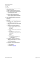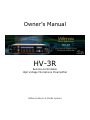
1
Owner’s Manual HV-3R Remote-Controllable High Voltage Microphone Preamplifier Millennia Music & Media Systems Table of Contents INTRODUCTION................................ 3 SAFETY PRECAUTIONS ..................... 4 FRONT PANEL FUNCTIONS ............... 6 Channel Display ..............................................7 Channel Number Indication .............................. 7 Gain Setting ...................................................7 Overload Indication .........................................7 Channel Mute .................................................7 Level Meter ....................................................7 REAR PANEL FUNCTIONS ................. 8 HARDWARE OPERATION................... 8 Menu Section Navigation ..................................8 Getting Started ...............................................8 Locking Front Panel in Remote ..........................8 Saving Settings to Memory............................... 9 Recalling Saved Settings ..................................9 LOCAL OPERATION ......................... 10 Gain Adjust .................................................. 10 Mute............................................................ 10 Polarity Flip .................................................. 10 Pad ............................................................. 10 Phantom Power............................................. 10 Link ............................................................. 10 Link Matrix .................................................. 20 Scene Window.............................................. 21 Project and Scene Management ...................... 21 Creating a Project ......................................... 21 Scene Window.............................................. 21 Safety Prompts ............................................ 21 Creating New Scenes .................................... 21 Renaming Scenes ......................................... 21 Reordering Scenes ........................................ 21 Recalling Scenes........................................... 22 Deleting Scene ............................................. 22 Locking Scene Window Functions .................... 22 Appending and Saving Scenes ........................ 22 Saving Scene Changes .................................. 22 REMOTE OPERATION WITH PRO TOOLS HD....................................... 23 Parameters for Remote Operation ................... 23 Setting Up the HV-3R for Remote Operation in Pro Tools........................................................... 23 Setting the MIDI Channel on the HV-3R .......... 23 Setting up the HV-3R in Pro Tools ................... 24 Choosing the MIDI Channel and Port Number in Pro Tools ..................................................... 24 If multiple HV-3R units are being used ............ 24 Other Options in Peripherals Window .............. 24 Remote Lock-Out Mode Check Box.................. 24 Assigning the HV-3R Outputs to Recording Interface Inputs in Pro Tools .......................... 25 Accessing Remote Controls of the HV-3R in Pro Tools Edit and Mix Windows ........................... 26 Pro Tools controls that do not work with the HV-3R:........................................................ 26 APPENDIX ...................................... 27 BASIC MENU MODE......................... 12 Ælogic Keyboard Shortcuts ............................ 27 Advanced Menu Mode ................................... 28 REMOTE OPERATION ...................... 13 Inductor Installation ................................ 30 Remote Operation of HV-3R with Ælogic Software (PC Only) ..................................................... 13 Getting Started ............................................. 13 Setting Unit ID(s) and IP Addresses ................ 13 Locking the Unit in Remote Mode .................... 14 Saving the LAN settings and setting the startup mode........................................................... 14 Save HV-3R Settings ..................................... 14 Setting Startup with these Settings ................. 14 Installing the Ælogic Software ........................ 15 Setting the Host Computer’s IP Address (XP) .... 15 ÆLOGIC OPERATION ...................... 16 Unit Status Window ....................................... 16 Red Icon ...................................................... 16 Green Icon ................................................... 16 Flashing Green Icon ...................................... 16 Purple Icon................................................... 16 Gray Icon ..................................................... 16 Unit Status Dialog ......................................... 16 Overview ..................................................... 17 Control Section ............................................. 17 Control Layout .............................................. 18 Unit Naming and Unit Name Dialog Box ........... 18 Millennia Media HV-3R AD-R96 USER GUIDE ...................... 31 MIDI............................................... 32 MIDI Implementation Charts .......................... 33 MIDI Gain Table ........................................... 35 Simple MIDI Controller .................................. 36 Setting up MIDI I/O in PD .............................. 36 Controlling the HV-3R with PD ........................ 36 Setting the MIDI Channel in PD ...................... 36 Basic Troubleshooting for PD patch ................. 36 TROUBLESHOOTING ....................... 37 SPECIFICATIONS ........................... 38 WARRANTY .................................... 40 To obtain warranty service............................. 40 Limits and Exclusions .................................... 40 Export Units ................................................. 40 page 2 of 40 Introduction Congratulations on your purchase of the Millennia Media HV-3R Remote-Controllable High Voltage Microphone Preamplifier. The HV-3R is the result of meticulous listening tests on numerous circuit, topology, and packaging designs. Your HV-3R is a finely tuned instrument intended for critical professional applications — we feel it offers the world's most sonically neutral microphone preamplification. The HV-3R is designed to be used: • • • Locally via the front panel controls – Referred to as “Local Mode”. Remotely via LAN from the HV-3R Ælogic PC remote control software. Up to 48 units can be simultaneously controlled with LAN. Remotely via MIDI. Up to 9 units can be simultaneously controlled with MIDI in Pro Tools, or 16 with some other MIDI device. The HV-3R can be used as a stand-alone, locally controlled eight-channel mic preamp similar to its sister product, the renowned HV-3D. Optional 130V mic inputs are available for use with high voltage microphones, such as DPA 4003 and 4012. Two additional buffered/balanced outputs (per channel) are available with the optional HROE expansion board (via DB25 connectors). Eight channels of internal A/D conversation are also available with the optional AD-R96 expansion card. Up to 48 HV-3Rs can be simultaneously controlled – a total of 384 channels on one system. A high-speed Ethernet control interface makes this possible without any significant system control latency, even if all 384 channels were to change parameters simultaneously. The MIDI control interface is compatible with Digidesign’s Pro Tools® “PRE” remote microphone preamplifier protocol. As defined by Digidesign, up to nine units can be simultaneously controlled with MIDI in Pro Tools. Up to 16 can be controlled per MIDI port with a standalone MIDI device, or other MIDI compatible software. page 3 of 40 rev 1.4.2 092309 Millennia Media HV-3R FCC Notice Information for the User This equipment has been tested and found to comply with the limits for a Class A digital device, pursuant to part 15 of the FCC Rules. These limits are designed to provide reasonable protection against harmful interference when the equipment is operated in a commercial environment. This equipment generates, uses, and can radiate radio frequency energy and, if not installed and used in accordance with this instruction manual, may cause harmful interference to radio communications. Operation of this equipment in a residential area is likely to cause harmful interference in which case the user will be required to correct the interference at his or her own expense. Safety Precautions For your safety and the safety of others, be sure to read and understand all safety and operational instructions before attempting to use the HV-3R. WARNING: The HV-3R internal circuitry carries lethal voltages. Carefully observe all warnings, precautions, and instructions on the HV-3R and as described in the instructions supplied with the unit. Water, Moisture, and Spillage – Do not attempt to use the HV-3R in, near, or around water or in unusually moist environments, such as near a sink or swimming pool. Prevent liquids or any other materials or objects from spilling or falling into the HV-3R unit. Heat And Ventilation – Be sure to allow adequate ventilation to HV-3R and avoid using or installing unit in close proximity to heat sources, such as heaters, stoves, radiators, power amplifiers, spotlights, or other heat-producing appliances or equipment. It is best to leave one rack screw space between units if possible. Power Sources and Power Cord Protection – The HV-3R Power Supply should be connected to a power source only of the type described in the operating instructions or as marked on the Power Supply. Route the power cord so that it is not likely to be walked on or pinched by having objects placed on it. Pay particular attention to plugs, receptacles, and the point where the AC power cord exits the HV-3R. Grounding – For your safety, it is extremely important that the grounding pin of the 3-wire power cable (included with 110 Volt units) be inserted into a grounding type 3-pin power outlet. If you are unable to insert the plug into an existing outlet, contact an electrician to install a properly grounded 3-pin power outlet, preferably that with OFI / CFI protection, if available. Millennia Media HV-3R Damage Requiring Service – This unit should be repaired or serviced by qualified personnel whenever: · The AC power cord has been damaged, or · Objects have fallen or liquid has spilled into any HV-3R unit, or · The unit does not function properly or exhibits a marked change in performance, or · The unit has been abused, dropped, or damaged, or · The unit has been exposed to rain or moisture. Servicing – Lethal voltages are found inside the HV-3R chassis. The user should not attempt to repair or service this unit. All servicing and/or repairs should be referred to Millennia. If, after reading all instructions, precautions, and warnings, you have remaining questions, please contact Millennia directly before attempting to use your HV-3R. Before connecting power to the HV-3R, assure that the rear panel voltage selection fuse block switch is set correctly. In the USA, Canada or Japan, HV-3R is shipped with the voltage selection block set to 100-120 VAC. If you change the voltage selection block to 200-240 VAC usage, be sure to change both fuses to the correct types. See “Rear Panel” instructions for proper fuse requirements. The HV-3R enclosure measures approximately 17” wide x 3.5” high x 16” deep and is designed for mounting into a standard 2U, 19” equipment rack. If the HV-3R is mounted in a road case or other rack which is prone to strong vibration or shock, it is highly recommended that the rear of the HV-3R be supported or otherwise reinforced to withstand such conditions. HV-3R contains discrete transistors, many running in Class-A bias. As such, the HV-3R runs quite warm and should be mounted for proper ventilation with at least one rack screw space open above and below the unit. HV-3R is designed on a common ground topology. For high quality operation, and for your own safety and the safety of others, do not defeat the power cord earth grounding pin. HV-3R Front-End Protection – Millennia Music & Media Systems enjoys a reputation for what many top engineers and producers call the world’s most musically accurate and dynamically uniform microphone preamplifier — the HV-3. But this thoroughbred design is not achieved without certain operating criteria. Back-to-back Zener diodes protect the super-matched discrete bipolar input transistors against high transient energy spikes common when inserting and extracting XLR connectors. To maintain top performance and protect the HV-3R’s sensitive HV-3 front-end, it is advised that you do not insert or extract XLR connectors with power on. Get in the habit of disabling AC power and waiting about ten seconds for the phantom power to fully “ramp down” before inserting or removing a microphone. This is good advice for protecting your microphone investments, as well. page 4 of 40 Any changes or modifications not expressly approved by MILLENNIA MEDIA, INC. (Millennia) could void your authority to operate this equipment under the EC, ICAN, or FCC rules. Copyright: You acknowledge that no title to the intellectual property in the HV-3R is transferred to you. The HV-3R serial number is located on the rear left side of each unit. We suggest that you record the serial number in the space provided below. Refer to it whenever you call an authorized Millennia repair facility or the manufacturer. Make sure that you register online or return your completed warranty card immediately. Features and specifications subject to change without notice. Inspection – Inspect packing box(es), HV-3R, and cable(s) for damage, unusual marks, or shortages. It is your responsibility to report damage, shortage, or mis-shipments in a timely manner. Millennia and/or its dealers will not be responsible for claims arising from damage in shipping, nor will claims for shortage or mis-shipments be honored, more than 10 days after ship date. Read this manual carefully and completely before attempting to use the HV-3R. Improper operation could result in damage to product. It is the user’s responsibility to understand the safe use and operation of this device. © 2008 – Millennia Media, Inc., All rights reserved Serial Number __________________________________________ Purchase Date __________________________________________ Where Purchased __________________________________________ The shipping box of the HV-3R system will include: • • • • Quick Start Guide Ælogic Software CD UL approved power cord (110 V countries only) Owner’s Registration Card, Register online at http://mil-media.com/registration.html or fill out the Owner’s Registration Card and return to Millennia at your earliest ability. The material contained in this manual consists of information that is property of Millennia and is intended solely for use by the purchasers of the equipment described in this manual. Without express written permission, Millennia prohibits the duplication of any portion of this manual or the use thereof for any purpose other than the operation and/or maintenance of the equipment described in this manual. This manual may not be duplicated in whole or in part without the written consent of Millennia. page 5 of 40 rev 1.4.2 092309 Millennia Media HV-3R 7 Front Panel Functions The 3/8” thick hand-machined aluminum front panel consists of two LCDs, one rotary encoder, 32 LED channel status indicators, and 18 functional pushbutton switches. 5 6 1. Large Rotary Encoder – Adjusts gain. 2. Column of Five Illuminated Pushbutton – Used to toggle a selected mic preamp’s parameters: • • • • • MUTE Audio POLarity inversion PAD 14dB attenuation +48Volt phantom power LINK Channels 3. Channel Status Indicators – Four LEDs per channel indicate status of channel’s parameters. Select button makes the selected channel’s controls editable. 4 4. Channel Display – Above the LED Matrix. It displays: • • • • • Channel Number Indication Gain Setting Overload Indication Channel Mute Level Meter 5. Menu Display – Indicates unit’s remote/local status and setup parameters. 3 6. Menu Navigation – A group of five switches controlling menu navigation. The EDIT section provides extensive parametric setup of the HV-3R mic preamp. 7. Power Switch – Turns the unit on and off. 2 1 Millennia Media HV-3R page 6 of 40 Channel Display The large LCD displays the channel number, the gain setting (8 dB to 69 dB in 1.0 db increments), overload indication via a small “OL” icon, channel mute, and a channel bar graph level meter. Channel Number Indication – Channel indication is shown numerically when in Local and LAN remote mode, and alpha-numerically when in MIDI remote. For example, if the unit is assigned Unit ID 01, channel 6 is displayed as “6” in Local and LAN modes. If assigned MIDI channel 01 “6a” is displayed (the letter indicates the MIDI channel assigned. a=1, b=2… p=16). Channel numbering is correlated to the Unit ID number in LAN remote, or MIDI channel in MIDI remote. For instance, in LAN remote if the unit ID is set to “03,” that unit’s channel numbering will display channels “17 – 24” (see remote operation for more on setting the Unit ID). Channel Mute – When a channel’s Mute is engaged, the word “MUTE” will appear in place of the channel’s gain setting (Channel 7 above). Level Meter – The level meter is a bar graph meter with eight segments. The approximate corresponding output levels are: OUTPUT BAR (balanced) OVL +22 dBu 7 +20 dBu 6 +16 dBu 5 +12 dBu 4 +8 dBu 3 +4 dBu 2 -10 dBu 1 -19 dBu When MIDI remote is enabled, each Unit has a letter (“a” through “p”) after each channel number indicating the MIDI channel (1 through 16). (see remote operation for more on setting the MIDI channel). Gain Setting – Gain is shown numerically under the channel number indication. For example, the number “35” would represent 35 dB of microphone voltage gain. Overload Indication – To the right of the channel number is an “OL” icon (Channel 2 above) which appears if the channel output equals or exceeds a peak of +22 dBu. Note that the HV-3R’s unclipped output is +32 dBu. “OL” does not indicate the clip point of the HV-3R’s analog sections. Rather, it indicates a warning to the user that the HV-3R output is approaching the clip level of many common outboard recording devices. page 7 of 40 rev 1.4.2 092309 Millennia Media HV-3R OPTION SLOT PANEL 8 7 8 7 9.0 MIDI IN 10.5 110-120 MIDI OUT MIDI THRU ETHERNET B OUTPUT 6 5 4 3 4 3 PUSH PUSH PUSH PUSH PUSH 5 C OUTPUT 2 5 2 1 6 1. AC Power – Worldwide (user configurable 100-240VAC) IEC power inlet. 2 1 LAN Remote ## Local 4. Analog I/O – Eight channels of XLR analog I/O connectors. Eight female XLRs for microphone-level input and eight male XLRs for line-level output. or 5. HROE Option I/O – two DB25s wired in the Tascam format for two additional buffered outputs. 3 7 If your unit powers up with one of the screens below (## will be the ID number or MIDI channel of the unit), it has been custom configured by the factory at the time of your order for a remote system. Push the enter key to select Local operation. 3. Option Slot – Above the MIDI and LAN ports is an option slot for the AD-R96 Expansion Card. This option slot can also host I/O for analog to digital converters and different remote control protocols. (Future options) 2 SERIAL Local Remote, Save > 2. MIDI and LAN Connection – Allow remote control of the HV-3R. 1 RESERVED For a description of the menu items and flow chart, go to the section “Basic Menu Mode”. Rear Panel Functions Channel 6 OUT 220-240 1 PUSH PUSH 48V IN PUSH 3 GROUND LIFT 4 5 6 7 MIDI Remote ## Local 8 + Pins 24 10 21 7 18 4 15 1 - Pins 12 23 9 20 6 17 3 14 Gnd Pins 25 11 22 8 19 5 16 2 6. Reserved DB25 – for future options. 7. Serial – For future control expansion. Hardware Operation Menu Section Navigation The Menu Section LCD can be navigated using the five buttons below it: Left, Right, ENTER, Up and Down. Choosing to Startup in Local or Remote Mode – The HV-3R is shipped to startup in Local mode. If the user wishes to startup the unit in Remote mode (LAN or MIDI) these steps must be followed. 1. 2. 3. 4. 5. Choose “Setup” from the main menu. Choose “Startup”. Choose “Mode”. Choose “Remote” (See sections on how to use with LAN or MIDI). Press the Up arrow three times to return to the top of the main menu. Locking Front Panel in Remote The front panel can be locked in Remote mode by pressing < and ^ at the same time when in Local mode. To unlock it to go back to Local mode, press < and ^ at the same time. This manual assumes the user has a basic knowledge of how to use the Left, Right, and ENTER buttons. The Up arrow in most cases acts as an escape from the current Edit screen, and when pressed repeatedly will eventually return to the top of the Main Menu (Shown Below). Getting Started The HV-3R is shipped to start up in Local mode. Below is the default menu screen that appears when a Unit is powered up for the first time. This menu screen is referred to as the top of the main menu. Millennia Media HV-3R page 8 of 41 4 Choosing Startup Settings – The HV-3R is shipped to startup with the default settings: • • • • • • • • • All functions turned off (MUTE, POL, PAD, 48V, LINK). Startup in Local mode with LAN Remote 01 set for remote operation (MIDI OFF). Startup with memory location 01. Front Panel Lock OFF Auto Save (for LAN Remote operation Only) ON IP Address set to 192.168.1.201. User Mode set to Basic. Menu timeout set to 180 sec. Gain range set to 69dB. If the user wishes to startup the unit with different settings these steps must be followed. Save your settings (see “Save Settings to Memory” then: 1. 2. 3. 4. 5. Choose “Setup” from the main menu. Choose “Startup”. Choose “Setup”. Choose the desired Setup from memory locations 1-16. Press the Up arrow three times to return to the top of the main menu. Saving and Recalling Settings Saving Settings to Memory – The HV-3R can store up to 16 different Setups in memory. All channel parameters and gain settings, Unit ID for LAN operation, MIDI channel for MIDI operation, and many other settings can be saved in memory and recalled when needed. 1. 2. 3. Choose “Save” from the main menu. Three choices will be presented. “Name”, “Save”, and “Del”. When saving a setup for the first time the “Name” choice may be desirable. This option lets you name the Setup before choosing the memory location. a. Name – Create a name for the setup by using the Up and Down arrows to change the character, and Left and Right arrows to choose character position. Press ENTER when finished and then choose the memory location as detailed in the next step (b). b. Save – Choose the memory location (1 through 16) to store the setup. Press enter when the desired memory location is displayed. There will be a prompt to “Overwrite Setup?” Choose “Yes” to save or “No” to abort. c. Delete – Choose the memory location (1 through 16) to delete. Press enter when the desired memory location is displayed. There will be a prompt that says “Are You Sure?” Choose “Yes” to delete or “No” to abort. Press the Up arrow two times to return to the top of the main menu. Recalling Saved Settings 1. Choose “Recall” from the main menu. 2. Choose the memory location (1 through 16) of the desired setup. 3. Press the Up arrow one time to return to the top of the main menu. page 9 of 40 rev 1.4.2 092309 Millennia Media HV-3R Local Operation The HV-3R is fully functional as a stand-alone microphone preamplifier without the need for any remote control. Local operation of the HV-3R is straight forward. To modify any control on a channel, press the desired channel’s Select button. It will then illuminate, indicating that the controls on the left side of the front panel are active for that channel. Press the five rectangular parameter buttons (Pad, Link, etc.) to change the channel’s parameters. The selected channel’s status LEDs will toggle on/off. Turn the knob to change gain. After 60 seconds of inactivity the selected channel will automatically revert to the unselected state. Push Select if you wish to activate again. This value can be modified in the Advanced Mode Link – This parameter allows the user to link the Gain and Mute parameters of any (or all) channels. To link, press the channel Select button of a channel to be linked, then press the Link button. Links are cleared when you go into the Remote mode. If you want to keep links, save them before you change modes. All linked channels will track gain in identical increments. For instance, if channels 1 and 2 are linked with respective gains of 10 and 20 dB, increasing the gain of either linked channel by 5 dB will result in channel gains of 15 and 25 dB, respectively. Gain linking is helpful when tracking with stereo or surround microphones. If Mute is selected on any linked channel, all linked channels will mute. Channel linking applies to gain and mute, only. No other parameters (pad, phantom, etc.) are linked by this parameter. Gain Adjust – To adjust a channel’s gain, press the channel Select button. It will illuminate. Now turn the knob. You will see a numerical gain change on the large display above that channel. Mute – To mute a channel, press the channel’s Select button, then press the Mute button. That channel will now be muted and the LCD gain setting will indicate the word “MUTE”. Linked channels will mute if any member of the link is muted. Polarity Flip – To invert the audio output polarity (180 degrees) of any channel, press the channel Select button, then press the POL button. That channel’s output signal will now be opposite of the input signal. Technically, this is not a “phase adjustment” as the waveform does not shift in time. Pad – To attenuate a channel’s output by 14 dB, press the channel Select button, then press the PAD button. That channel’s output signal will be padded by 14 dB, though the gain shown in that channel’s LCD will not change. Phantom Power – To apply 48 volt phantom power to a channel, press the channel Select button, then press the 48V parameter button. That channel will now have 48V phantom power applied equally to both pin 2 and pin 3 of that channel’s input XLR. CAUTION – DO NOT PLUG A MIC IN WITH THE PHANTOM POWER ON. IT CAN DAMAGE THE MICROPHONE AND THE PREAMP INPUT Millennia Media HV-3R page 10 of 40 LAN/MIDI Remote Local Remote Name Enter Name Save Where? <”## “Name“ > Overwrite Setup? No, Yes Save Recall Save Setup Name, Save, Del Recall <”## “Name“ > > Save Where? <”## “Name“ Delete Setup <## Name > Overwrite Setup? No, Yes MIDI Unit ID ## MIDI ## page 11 of 40 Status See Advanced Utility See Advanced Startup IP Address Mode Are You Sure? No, Yes Unit ID Startup Mode Local, Remote Setup Starting Setup <## “Name” IP Address, Save DHCP > Auto Save On, Off rev 1.4.2 092309 IP Address, Save <192.168.1.201 Startup Locked Locked, Unlocked Mode Basic, Advanced Millennia Media HV-3R Basic Menu Mode Remote Mode 1) Local Local Mode 1) Save – Menu for saving, naming, and deleting setups stored in memory. (A) Name – Allows nine character naming of each memory location. (B) Save – Saves all current setup parameters to a specified memory location. (i) Location (a) Overwrite (C) Delete – Deletes a saved setup from memory, effectively setting all parameters of that setup to default. (i) Are You Sure 2) Recall – Recalls all parameters of a previously saved Setup. (A) Location 3) Setup – Menu for changing setup parameters of the HV-3R (A) Unit ID ## (1-48) – Chooses Unit ID used to identify the unit over the LAN. (B) MIDI Channel Assign (OFF, 1-16) – Chooses MIDI channel used to communicate with the HV-3R. (C) Startup – Chooses startup options to be loaded when the HV-3R is powered on. (i) Mode – Chooses to startup in Local or Remote Mode. (a) Local (b) Remote (ii) Setup – Chooses memory location to be loaded. (a) Location (iii) Auto Save – Saves control settings 3 seconds after last change when in LAN remote mode (a) On (b) Off (iv) Startup Locked (a) Front panel controls locked in Remote Mode (b) Front panel unlocked (D) IP Address – Chooses user specified IP Address or allows DHCP server to allocate addresses automatically. (i) DHCP (ii) ###.###.###.### (E) User Mode – Grants or denies access to additional features and functions of the HV-3R. (i) Basic (Default) (ii) Advanced (locked out) Millennia Media HV-3R page 12 of 40 Remote Operation 3. Ethernet and MIDI control cannot be used simultaneously in an HV-3R remote system – only one remote control protocol can be used in an HV-3R network. Unit ID 01 Remote Operation of HV-3R with Ælogic Software (PC Only) 4. The HV-3R is shipped with a proprietary Graphical User Interface, Ælogic, created specifically for the task of controlling up to 48 HV-3Rs simultaneously. There are a few steps that must be completed to insure proper communication over the LAN. Press the Right arrow three times and hit ENTER. IP Address, Save 192.168.1.201 In order to control the HV-3R via LAN, first make sure that there is a cable connected between the computer’s LAN port and the LAN port of the HV-3R. If more than one preamp is being used, a network must be setup. You will need a 100 Mbps or faster router/switch such as the LinkSys EZXS55W or equivalent (for 4 HV-3Rs). For larger systems, use a wider switch. We recommend using a network that is dedicated to only the HV-3Rs for greater reliability. Getting Started Don’t Run Ælogic While Setting Up Unit IDs and IP Address. Setting Unit ID(s) and IP Addresses – Each HV-3R needs to be set to its own unique Unit ID and IP address. If units have the same ID or IP addresses there will be a conflict and the system will not work properly. 1. Now Choose “Unit ID”, set it to 01 (or other number if using multiple units) and hit ENTER. 5. Press the Down arrow and the Right arrow three times. 6. Use the Up/Down arrows to select a number. We have set 192.168.1.201 and ID 01 as a default. We recommend a sequential numbering scheme: IP Address Unit ID 192.168.1.200 Host Computer 192.168.1.201 HV-3R ID 01 192.168.1.202 HV-3R ID 02 192.168.1.203 HV-3R ID 03 192.168.1.2nn HV-3R ID nn 7. Hit ENTER twice to save. 8. Press the Up arrow two times to return to the top of the main menu. Choose “Setup” from the main menu of the HV-3R. Dynamic Host Configuration Protocol (DHCP) is also an option for “IP Address”, but we don’t recommend using it unless you are familiar with networking and have the proper network hardware. Local <Recall, Setup 2. Choose “MIDI”, make sure it is set to “OFF” and hit ENTER. Setup Unit ID, MIDI > MIDI OFF page 13 of 40 rev 1.4.2 092309 Millennia Media HV-3R Locking the Unit in Remote Mode – The unit may be locked in the remote mode on startup to prevent tampering. Navigate to “Setup” and select “Startup” Press the right arrow twice to select “Locked” Choose “Locked” (or Unlocked) and press ENTER. You can manually go in and out of this mode from the front panel by putting the unit into the Local mode. Be sure you are at the top of the menu tree by pressing the up arrow several times. Pressing the < then key places the unit in locked Remote mode. Remote mode can only be exited to Local mode by again pressing the < and keys. Saving the LAN settings and setting the startup mode. Save HV-3R Settings 1. Choose “Save” from the main menu. 2. To name the saved setup choose “Name” and use the arrow buttons to choose the desired title, hit ENTER. Otherwise choose “Save” and continue to step 3. 3. Choose the desired memory location and hit ENTER. 4. When prompted to “Overwrite Setup?” choose “Yes”. 5. Hit the Up arrow two times to return to the top of the main menu. Setting Startup with these Settings 1. Choose “Setup” from the main menu. 2. Scroll right to “Startup” and hit ENTER. 3. Select “Mode” to choose to startup in “Local” or “Remote” and “Setup” to choose the startup memory location. Millennia Media HV-3R page 14 of 40 Installing the Ælogic Software – Insert the Ælogic Disc into the computer (Windows XP or Vista only) that will be used to control the HV-3R(s). The following screen will appear. If it doesn’t, browse to the CD and open setup.exe 2. 3. 4. 5. 6. Double click on Internet Protocol (TCP/IP) to open its properties. Select “Use the following IP addresses. Enter 192.168.1.200 in IP Address. Enter 255.255.255.0 in Subnet mask. Click OK and continue to exit out of Network Connections. Select the desired options and click on “Install”. The following screen will appear if the install is successful: 7. 8. Connect the Host Computer and HV-3R(s) LAN Ports to the same router/switch. Run the Ælogic Software. Be sure the computer is set to IP address 192.168.1.200 Setting the Host Computer’s IP Address (XP) 1. Go to Network, right click on the Local Area Connection and open Properties. page 15 of 40 rev 1.4.2 092309 Millennia Media HV-3R Scene Window Unit Status Window Control Section Ælogic Operation Millennia’s Ælogic remote control software is straightforward to operate. Here is an in-depth description of the available functions of the GUI. Refer to Appendix for a list of keyboard shortcuts. Unit Status Window – The example screen above shows a Unit Status window in which six HV-3R units (48 channels) are connected to the remote network. The Unit Status window displays an icon of each HV-3R unit on the network. The status of each HV-3R is represented by its icon’s color code, as follows: Red Icon – “Unit ID Has a Conflict with Another Unit”. If two or more HV-3Rs share the same Unit ID number or IP address, their icons will turn red, and will show identical IDs or IP addresses until the conflict is resolved. Setting a Unit ID or IP address must be done locally on each HV-3R. Other errors could also cause a red icon, such as over-temperature, power supply out of range, other networking errors, etc. Green Icon – “Functioning Normally”. Remote unit functioning normally. Millennia Media HV-3R Flashing Green Icon – “Functioning Normally, Local Mode”. Remote unit is functioning normally but is in the local mode. If the unit is in Local mode when Ælogic is started, it won’t appear. Be sure to change the unit to Remote mode so the software can recognize the HV-3R. Purple Icon – “Unit ID Is Offline”. A unit used to be connected to the network and set to this Unit ID. The unit is missing from the network. It was either turned off or the Ethernet was disconnected or both. Gray Icon – “Unit ID Is Inactive”. No unit is connected to the network and set to this Unit ID. Unit Status Dialog – Double left mouse click on any icon brings up that unit’s Unit Status dialog box displaying the following information: 1. Unit Functionality 2. 48v Monitor 3. 24v Monitor 4. 5v Monitor 5. 3.3v Monitor 6. Temperature 7. MAC Address 8. IP Address page 16 of 40 Overview Overview – Expands the channel control area to show multiple units. Virtual switches are replaced by small virtual LEDs. Link switch is replaced by link group number only. Other attributes are shrunk to fit. All functions remain accessible and adjustable on the Overview Screen. Ælogic is always the master control when the unit is in Remote Mode. Any changes made in to the unit’s front panel in the Local mode will be overwritten when the HV-3R is put back into Remote Mode. Above is a screen-shot of the OVERVIEW. Control Section Basic Navigation and Behavior The channel controls are grouped into their respective HV-3R 8-channel Units. The screen shot on the previous page, shows units #1 and #2. You can left-click on any unit icon shown in the Unit Status window to immediately bring that unit’s channel controls into the main screen. Note the scroll bar at the bottom of the screen. It allows the user to quickly scroll to any unit in the network. You can also move the Control Section by using the Left and Right arrow keys on the keyboard. Pressing an arrow key once corresponds to scrolling in that direction by one channel strip. page 17 of 40 rev 1.4.2 092309 Millennia Media HV-3R Channel Strip Display and Functions Control Layout The main control section, starting from the top down, graphically represents these features: 1. 2. 3. 4. 5. 6. 7. 8. 9. 10. 11. 12. Unit Name Channel Number Polarity Invert Button Pad (14dB Attenuator) Select Button 48V Phantom Select Button Mute Select Button Gain fader Plasma-type Metering Channel Gain Link Assignment Scribble Strip Channel Number (shown at top and bottom of strip for ergonomic clarity) Unit Naming and Unit Name Dialog Box (right-click on unit name) – Each Unit’s name is shown above its eight-channel grouping. The default name for each unit is its Unit ID. For instance, “UNIT 1” corresponds with channels 1-8 and “UNIT 3” corresponds with channels 17-24. Right-clicking on the Unit Name area opens the Unit Name dialog (shown above) which allows textual naming of that unit. A section for notes is also available to include any supplementary information about the unit. In order to name multiple units quickly, the “Prev” and “Next” buttons allow the user to scroll through units without closing the dialog box. If a unit has been re-named from the default, the new Unit Name will now be displayed in the Unit Name box. The Naming Window can also be accessed from the pull-down menus (Edit>Unit Naming). Millennia Media HV-3R Channel Number – Channel numbers appear at the top and bottom of the channel strip. The preamp with Unit ID 1 will be assigned channels 1-8. Unit ID 2 will be assigned channels 9-16 ….Unit ID 48 will be assigned channels 377-384. POLarity Flip – Inverts channel audio output polarity (180 degrees). The channel’s output waveform becomes a mirror of the input signal. This is not a “phase adjustment” as the output signal does not shift in time relative to the input signal. Button illuminates green. PAD – Attenuates channel output by 14 dB. The gain setting remains unchanged. Button illuminates green. 48V – Applies 48 volt phantom power to the respective mic input channel. Phantom power is applied equally to both pin 2 and pin 3 of that channel’s input XLR. Button illuminates yellow. CAUTION – DO NOT PLUG A MIC IN WITH THE PHANTOM POWER ON. IT CAN DAMAGE THE MICROPHONE AND THE PREAMP INPUT MUTE – Mutes channel output. When channel is muted, the meter will continue to operate allowing the user to view audio activity on that channel without passing live audio. Mute parameter is linkable. Button illuminates red. page 18 of 40 Channel Gain Faders/Gain Display – A traditional looking “mixer fader” that adjusts preamp channel gain. A text box below the fader indicates the actual channel gain setting in decibels. Standard gain range is 8 dB to 69 dB. A range of 8 dB to 80 dB is a no-charge option. Gain is segmented in 1 dB steps. The Up and Down keyboard arrow keys can also be used to adjust the channel gain in 1dB steps. Linked Gain – Linked Gain faders move together maintaining the same distance they had when first linked together. Once one fader reaches the upper or lower extreme, the other faders in the same link group stop moving in that direction. Linked Gains can be trimmed by holding down the Alt key while using the left mouse button. When the Alt key is released, the channel reverts to linked mode. Linked Mute – Linked Mute parameters will turn on and off together unless “Mute linked channels” is unchecked in the Preferences dialog box (Setup> Preferences>“Mute linked channels”). If this box is unchecked, the mute parameters will act independently just like the other parameters. Scribble Strip (right-click on scribble strip) A text box in which channels can be named, and notes can be written and stored. See the screenshot on the previous page. Meter Preferences Dialog – The Meter Preferences dialog box provides for customization of meter display and functions. It can be accessed three different ways: Shortcut Control-M, right-clicking the meter display in the channel strip, or from the pull down menus (Setup>Preferences>Metering). To name multiple channels quickly, “Prev” and “Next” buttons allow the user to scroll through channels without closing the dialog box. If a channel has been re-named from the default, the new Channel Name will now be displayed in the Unit Name box. The Naming Window can also be accessed from the pull-down menus (Edit>Channel Naming). You can select either Meter Scale dBu (Usually for an analog system) or dBFS for a digital system. Peak Hold Time affects the numerical level indicator above the meter and the floating line over it. Link Assignment – The Link parameter provides a Gain and Mute linking utility. Linking applies to Gain and Mute parameters only; no other parameters are linkable. The LINK button links and unlinks a channel from a selected “link group”. There are ten selectable link groups that can be chosen from the drop down box next to the LINK button or the Link Matrix. When a link group is chosen, the LINK button is automatically selected and illuminates red. One link group can be assigned per channel. If no link group is selected, a depressed LINK switch will effectively do nothing. page 19 of 40 rev 1.4.2 092309 Millennia Media HV-3R Link Matrix The Link Matrix dialog box provides for easier linking and unlinking of channels and can be accessed via shortcut ctrl-L or from the pull down menus (Edit>Link). • • • Name a Link Group by right clicking a Link Group number. See the members of a group by double clicking the group’s name. Right click a link to bring up the channel naming dialog box. Millennia Media HV-3R page 20 of 40 The Scene List – Scenes are arranged sequentially within the Scene Window (000, 001, 002, etc.). The Scene List is a scrollable list of all Scenes within the Scene Window. Left-clicking a Scene Number/Name will highlight it. No system functions will change until the Recall button is clicked or until the desired scene is double-clicked. Project and Scene Management Creating a Project – Before anything (new scenes, changes to scenes, etc.) can be saved, a project itself must be created by doing a Save. Use File>Save to name the Project and find a location to save it. File>Save (ctrl-S) will save any updates or changes to the project unless a new name is desired (use File>Save As (shift+ctrl S)). Scene Window – Underneath the Scene Window there are four buttons “Recall”, “New”, “Delete”, and “Lock.” The functions of these buttons are explained below. Scene Window The Scene Window is found in the upper left corner of the screen. A Scene remembers and recalls all parameters of the current software environment (gains, mutes, links, etc.). Scenes are used for applications such as concerts or stage plays in which new acts or set changes require different microphone gains, mutes, links, metering, etc. There are a few physical aspects to the scene window worth noting before creating new scenes and projects: “Active Scene: ###” – The active scene number displays the number of the scene that is currently active. Scene Name Display – Just below the active scene number is a text display that defaults to “Blank Scene.” This area displays the user designated name of the currently active scene. “000 Blank Scene” – The default scene that is automatically opened when the Ælogic is first loaded or when a Project, New or Saved, is opened. The Blank Scene is to be used as a null starting point. Selecting scene 000 will force all parameters of all networked units to their “off” or “lowest” settings. This default scene cannot be overwritten. page 21 of 40 Safety Prompts – In order to exercise caution when using the Scene Window Functions, safety prompts are available in case buttons are pressed accidentally. Safety prompts can be enabled for: • New Scene • Recall Scene • Scene Delete • Scene Re-Ordering To turn safety prompts on and off go to “Setup>Preferences” in the pull-down menus. The section labeled “Scene Prompts” will have check boxes for the four choices. Creating New Scenes – Scenes are created by using the “New” button below the scene window. Once this button is pressed the “Enter Scene Name” dialog box appears. The scene name can be entered in the upper text box and a section for Notes is also available to include any supplementary information about the scene. Once the scene is named it will be appended to the Scene Window (next available scene number). A newly created scene will assume all parameters and settings of the active scene. Creating or naming a scene does not make it active. Only Recall or double-clicking can activate a scene. Renaming Scenes – Once scenes are created they can be renamed by right-clicking on them. A dialog box labeled “Rename Scene” will appear with the same choices as the “Enter Scene Name” dialog box. Reordering Scenes – Scenes are moved by left-clicking and dragging them to the desired location. Once a scene is moved, Ælogic will automatically update the numbers in front of each scene name. rev 1.4.2 092309 Millennia Media HV-3R Recalling Scenes – Scenes can be recalled two different ways: 1. 2. Highlight the desired scene and click the “Recall” button. Double click the scene name. The scene’s parameters will be transmitted to all HV-3R units on the network. Scenes are not saved until you save the project. (see Saving Scene Changes below for information on how to save a scene) Deleting Scenes – Scenes can also be deleted two different ways: either highlighting the desired scene and pressing the “Delete” button or highlighting it and pressing the delete key on the keyboard. Be careful when deleting scenes as the “Undo” function does not work on deleted scenes. When a scene is deleted, higher scene numbers will automatically decrement. If an attempt to delete the currently Active Scene is made, a prompt will pop up explaining that it is active and cannot be deleted. Locking Scene Window Functions – Sometimes it may be necessary to disable the functions of the Scene Window. The “Lock” button serves this purpose. When the button is engaged, the other three functions will turn dark grey and will no longer be functional. Parameters in the Control Section (faders, Links, function buttons, etc.) will still be functional. Appending and Saving Scenes – Whenever a change is made to any parameter or function, an asterisk (*) will appear next to the active scene in the Scene Window (with the exception of the Blank Scene). The asterisk will remain visible until the Project is saved. The asterisk indicates a “dirty event” – meaning that changes have been made since the last Project save. Saving Scene Changes – All Scenes shown in the Scene Window are saved each time the Project is saved (File>Save OR ctrl-S). Any changes to a Scene (a “dirty event”) will be lost if the Project is not saved before recalling another Project or if the Project is not saved before exiting the GUI. Millennia Media HV-3R page 22 of 40 Remote Operation with Pro Tools HD (Version 7.3 Tested) Setting the MIDI Channel on the HV-3R 1. Parameters for Remote Operation LAN Remote ## Local Pro Tools can control the following front panel parameters on the HV-3R: 1. Polarity 2. Pad (14dB) 3. 48V (Phantom Power) 4. Gain (08 dB to 69 dB) 2. 3. Pro Tools does however turn the Mutes on each HV-3R channel off upon sync up. 4. Connecting the HV-3R to a Pro Tools Compatible Recording Interface Choose “MIDI”, Setup Unit ID, MIDI > In order to record audio sent from the HV-3R you must first connect the outputs of the HV-3R to the inputs of your recording interface. 5. HV-3R Analog XLR Outputs – Connect the eight female XLR analog outputs on the back panel of the HV-3R to the eight desired analog inputs on your recording interface. (If your recording interface only has DB-25 inputs you will require an eight female XLR to DB-25 adapter cable.) HV-3R HROE Optional Expansion Board – Analog DB-25 OUTPUTS – Connect the DB-25 analog outputs on the back panel of the HV-3R to the desired DB-25 inputs on your recording interface. HV-3R AD-R96 Optional Expansion Card – Digital DB-25 OUTPUTS – Connect the DB-25 digital outputs from the AD-R96 to the desired DB-25 Digital inputs on your recording interface. Connecting the HV-3R to a MIDI Interface Make sure your MIDI Interface is properly connected and communicating with Pro Tools before use with the HV-3R. 3. Press the right arrow button 3 times until “Setup” has the blinking line under it. Local <Recall, Setup > Setting Up the HV-3R for Remote Operation in Pro Tools 2. If so press ENTER to display this screen. Local Remote, Save > Pro Tools does not control the Mute parameter on the HV-3R. Use the Pro Tools mixer’s individual channel strip’s mutes. 1. When you first turn on your HV-3R it should be in the Local Mode. You go can to step 3, if not start here. Connect the MIDI OUT port on the MIDI Interface to the MIDI IN port on the HV-3R. Connect the OUT of that unit to the IN of the next unit and so on. Connect the MIDI OUT port on the last HV-3R of the system to the MIDI IN port on the MIDI Interface. Press the up or down arrows to choose the MIDI channel for the HV-3R and press ENTER when finished to return to the Setup menu. MIDI OFF 6. Choose “Unit ID” and set it to the same number as the MIDI channel. This facilitates any future firmware upgrades. 7. Press the up arrow twice and press enter to return to remote mode. 8. Now you should see MIDI Remote with the channel number you selected, and each channel number should have a little letter next to it designating that a MIDI channel has been assigned. MIDI Remote ## Local REMEMBER the channel you selected as it will be important when setting up the HV-3R in Pro Tools. If multiple HV-3R units are being used, set each unit to a different MIDI channel. Also remember which unit is assigned to each MIDI channel so you don’t get them confused when setting them up in Pro Tools. If two units share the same channel they will both respond to the same channel messages from Pro Tools and will not function independently. page 23 of 40 rev 1.4.2 092309 Millennia Media HV-3R Setting up the HV-3R in Pro Tools Before setting up the HV-3R in Pro Tools, make sure all Digidesign software and hardware and your MIDI interface are installed, connected, and working properly. Once a New or Existing session is opened follow this procedure to control your HV-3R parameters in Pro Tools. Choosing the MIDI Channel and Port Number in Pro Tools 1. 2. 3. 4. 5. 6. Click the “Setup” pull down menu and choose “Peripherals…” (the Peripherals window will pop up looking like this). Click the “Mic Preamps” tab. Under “Type” click the pop-up menu and choose PRE. Now the pop-up menus under the “Receive From” and “Send To” columns will become active. Under the “Receive From” pop-up, choose the Port that your HV-3R’s MIDI OUT port is connected to and the MIDI Channel Number that you assigned it. Under the “Send To” pop-up, choose the Port that your HV-3R’s MIDI IN port is connected to and the MIDI Channel Number that you assigned it. Click OK to activate these settings. Millennia Media HV-3R If multiple HV-3R units are being used: You can add up to nine HV-3R units to be controlled in Pro Tools. In the Peripherals dialogue window, choose PRE under the “Type” column as many times as desired for the number of HV-3Rs you have, then assign the IN and OUT port numbers and MIDI channels that correspond to each HV-3R. Remember that you can’t have two HV-3Rs on the same MIDI channel. Other Options in Peripherals Window Reset Button – When pressed, this button will Reset all HV-3R values to zero, meaning all Mute, Polarity, Pad, and 48V parameters will be turned off and gain settings set to the lowest 08 setting. We recommend you reset all HV-3Rs to be sure they are in sync Pro Tools does not reliably poll the units to retain current settings. Retain Current Settings Check Box Leave this box unchecked, when Pro Tools and your HV-3R sync up, the HV-3R will acquire the settings for all parameters currently set in Pro Tools, and will always update accordingly. Remote Lock-Out Mode Check Box – The HV-3R doesn’t respond to this message, so don’t worry about it. It is only used by the Digidesign PRE to lockout front panel controls. page 24 of 40 Assigning the HV-3R Outputs to Recording Interface Inputs in Pro Tools In order to have Mic Preamp controls available in Pro Tools you have to map the outputs of the HV-3R to the inputs on your Recording Interface. Make sure you know which outputs of the HV-3R are going into which inputs on your Recording Interface before proceeding. 1. 2. 3. 4. 5. Click the “Setup” pull down menu and choose “I/O…” (see I/O Setup window above) Click the “Mic Preamps” tab. In the left column “PRE #1” should be displayed, and in the right column you should see your Recording Interface and the channels it has available with little boxes under each one. Click the box for the Input on your Recording Interface that corresponds to the first output of the HV-3R. The first output will appear in the box you clicked while the next seven outputs will appear in the boxes to the right. You can move the outputs of the HV-3R around. Be sure that the chosen inputs in Pro Tools correspond to how they are connected physically to the Recording Interface. If multiple HV-3R units are being used make sure that none of the channel outputs of the HV-3Rs share inputs on your Recording Interface. This will cause many problems. It is recommended that you connect Outputs 1-8 of the first HV-3R to Inputs 1-8 on the Recording Interface and then Outputs 1-8 on the second HV-3R to Inputs 9-16 on the Recording Interface and so on. It is crucial that all outputs and inputs correspond correctly or else when you try to control an HV-3R channel in Pro Tools it will control the wrong one or none at all. page 25 of 40 rev 1.4.2 092309 Millennia Media HV-3R Accessing Remote Controls of the HV-3R in Pro Tools Edit and Mix Windows When you add new audio tracks that have inputs corresponding to outputs from an HV-3R, there will be special controls available on each channel in Pro Tools. To access controls in the Edit Window: • Select View > Edit Window > Mic Preamps from the drop down menus. If you click the button labeled “Mic Type” in the previous diagram, a larger Pro Tools fader with the same buttons will appear such as the example to the right. Use your Pro Tools Manual as a reference on how to use the “target button” in the upper right corner of the pop up fader. To access controls in the Mix Window: • Select View > Mix Window > Mic Preamps from the drop down menus. Source / Impedance (N/A to HV-3R) Mic Type (N/A to HV-3R) Polarity Flip HP Filter (N/A to HV-3R) -18dB Pad Insert (N/A to HV-3R) 48V Phantom Gain Setting The HV-3R is controlled by the panel above, in the Pro Tools Mix and Edit Windows. The buttons highlighted in white are the ones that the HV-3R responds to. The button labeled “Gain Setting” can control the HV-3R’s gain, but since the lowest gain setting on the HV-3R is 08 dB, the first three settings (0dB, 3dB, and 6dB) won’t change the gain on the HV-3R. The other buttons are reserved for use with the Digidesign PRE. Pro Tools controls that do not work with the HV-3R: • • • • • • • Mute Gains <8dB Insert Mic Type HP filter Source Impedance Pad is 14dB, not 18dB Millennia Media HV-3R page 26 of 40 Appendix Ælogic Keyboard Shortcuts Keys Function Alt Click-and-Drag fader of linked group Allows you to trim member of group Alt E Edit Menu Alt F File Menu Alt F4 Close program Alt S Setup Menu Click and Drag on Link Matrix Drag across to link/unlink channels Click and Drag POL or Pad or 48V or Mute or Link Drag across channel buttons to select or unselect Click and Drag Scene name Drag to new place in list Ctrl H Help Menu Ctrl I Unit identity check Ctrl L Brings up Link Matrix Ctrl M Meter preferences Ctrl N Create new project Ctrl O Open project Ctrl S Save Ctrl Z Undo (10 levels) Double Click Group Title in Link Matrix Lists channels that are members of the group Double Click on unit icon in Unit Status box Gives voltage, temperature and network data of unit. Double Click Scene name Loads Scene F1 Help Menu Left/Right keys (on controls) Move channels one over Right Click Group title name in Link Matrix Edit name Right Click link box in Link Matrix Edit channel name Right Click on channel name below fader Edit channel name Right Click on meter Edit meter settings Right Click on unit name above faders Edit unit name Right Click scene name Edit scene name Shift Ctrl S Save as Up/Down keys (on controls) Increment/Decrement gain by 1dB page 27 of 40 rev 1.4.2 092309 Millennia Media HV-3R Advanced Menu Mode To access push both Left and Down buttons at the same time after selecting Advanced Mode. These controls can get you into trouble, so be careful with function like clearing memory and resetting defaults. They have no undo. LAN/MIDI Remote Local Remote See Basic Save See Basic Recall See Basic Setup See Basic Status IPAddr Pwr Ver MAC Current IP 192.168.1.201 Power 470C, 3.3 > Firmware Version Ver. 0.132.3 MAC Address 001BFF01F080 Dflt ClearMem Timeout AdvP Restore Default? No. Yes Clear Flash? No. Yes Menu Timeout Sec None, 60, 180 Adv. Parameters Gain Range Utility Test Mode Gain Range Max 69dB Test Mode Switch Test 1) Test Mode LED Test Test Mode LCD Test System Status – Displays the status of various parameters currently active on the unit. (A) LAN Address – Displays the current IP Address the unit is using. (B) Power Supply – Displays the temperature and various voltages of the power supply. (i) Temp ###C (ii) +48 (iii) +24 (iv) +5 (v) +3.3 (C) Firmware Ver ##.## – Displays the current firmware version running on the unit. (D) MAC Address – Displays the MAC Address assigned to the unit. Millennia Media HV-3R Test Mode Encoder Test 2) Test Mode Watchdog Test Test Mode Factory Test Utilities (A) Restore defaults – Restores to factory defaults without affecting user memory. Don’t do this unless you are instructed by Millennia Service. (B) Clear User Memory – Clears user memory locations (C) Menu time out – Sets length of time (seconds)before returning to the top of the main menu. (i) None, 60, 180 (D) Advanced Parameters – Allows access to advanced or extended parameters. (E) Gain Range – Choice between a maximum gain of 69dB or 80dB. (special button combination to change: Left Right Down, Down.) (F) Factory Test Mode (i) Switch test (ii) LED test (iii) Encoder test (iv) Watch dog (v) Factory test page 28 of 40 HROE (option) Jumper Diagram Polarity and Pad Functions • • The XLR outputs are A. They are locally or remotely controlled. The Polarity and Pad on Outputs B and C can be configured to either follow A or remain fixed at the values below by moving the associated jumpers. Channels *Polarity Follows A Polarity Fixed *Pad Follows A Pad Fixed at -13.5 dB B 1-4 J1 Pins 1,2 J1 Pins 2,3 J11 Pins 1,2 J11 Pins 2,3 B 5-8 J15 Pins 1,2 J15 Pins 2,3 J13 Pins 1,2 J13 Pins 2,3 C 1-4 J3 Pins 1,2 J3 Pins 2,3 J4 Pins 1,2 J4 Pins 2,3 C 5-8 J12 Pins 1,2 J12 Pins 2,3 J6 Pins 1,2 J6 Pins 2,3 *Default page 29 of 40 rev 1.4.2 092309 Millennia Media HV-3R Inductor Installation This equipment has been tested and found to comply with the limits for a Class A digital device, pursuant to part 15 of the FCC Rules. These limits are designed to provide reasonable protection against harmful interference when the equipment is operated in a commercial environment. This equipment generates, uses, and can radiate radio frequency energy and, if not installed and used in accordance with this instruction manual, may cause harmful interference to radio communications. Operation of this equipment in a residential area is likely to cause harmful interference in which case the user will be required to correct the interference at his or her own expense. This product was testing for FCC compliance using a clamp-on ferrite inductor. If you are using Ethernet, the inductor included with this unit must be attached to the Ethernet cable at the end connected to the HV-3R’s RJ-45, 5 cm from the rear panel, to block possible RF radiation coming from the cable. 5 cm Snap the inductor closed. Any changes or modifications not expressly approved by Millennia Media, Inc. (Millennia) could void your authority to operate this equipment under the EC, ICAN, or FCC rules. Make a loop near the connector end and place the loop inside the inductor. Millennia Media HV-3R page 30 of 40 Clocks - the AD-R96 should have only one clock source. If running with the internal clock, make sure SW4 is in the INT position and no external clock is connected. AD-R96 (Option) User Guide Protecting Against Electrostatic Discharge Static electricity can harm delicate components on the AD-R96 board. To prevent static damage, discharge static electricity from your body before you touch any electronic components. You can do so by touching an unpainted metal surface on the HV-3R’s chassis. Sync Signals on the BNC connectors should conform to the AES-3id specification. AES-3, through an XLR-to-BNC transformer (Neutrik NADITBNC-F or equivalent) will work fine. S/PDIF works, but is not specified. Unplug the HV-3R’s AC power cord before inserting or removing the AD-R96 board Sample Rate kHz SW2 SW1 44.1* X1 44 Clock Source Internal SW4 INT 48 X1 48 External* EXT 88.2 X2 44 96 X2 48 *The arrows point to the default jumper positions. J2 Clock Termination J3 Clock Output Word Clock* on 75 ohms* on AES off Unterminated off Clock Input J4 J5 Word Clock* 2,3 2,3 AES 1,2 1,2 DB25 Pin Outs Channel 1/2 3/4 5/6 + Pins 24 10 21 7 18 4 15 1 - Pins 12 23 9 20 6 17 3 14 Gnd Pins 25 11 22 8 19 5 16 2 page 31 of 40 7/8 rev 1.4.2 092309 Millennia Media HV-3R MIDI If the HV-3R is going to be controlled via MIDI without Pro Tools, a MIDI controller can be programmed, or MIDI manipulation software such as PD (Pure Data) can be used to control the preamp’s functions. This is a brief overview of how MIDI works in regards to the HV-3R in order to help in the process of programming a controller or software properly. Brief Description of MIDI Control Change Messages The HV-3R responds to MIDI Continuous Controller / Control Change data in the form of 3 byte hexadecimal messages. The form of these messages is: Byte 1 (Status Byte) Byte 2 (Data Byte 1) Byte 3 (Data Byte 2) 0xBX 0xCC 0xVV (The 0x part of each message designates that it is in Hexadecimal form and can be ignored.) In Byte 1 the “B” designates the message as a Control Change message, and the “X” is a value from 0 to F in hex, designating MIDI channel 1-16. The first byte is known as the Status Byte. In Byte 2 the “CC” is a value from “00” to “7F” in hex (0 to 127 in decimal). This byte designates which Controller Number is being sent. This byte is known as Data Byte 1. In Byte 3 the “VV” is a value from “00” to “7F” in hex (0 to 127 in decimal). This byte designates the Value being sent. This byte is known as Data Byte 2. MIDI Implementation for the HV-3R The following Table provides a comprehensive description of which MIDI Controller Numbers control each function on the HV-3R. The 3rd and 4th columns represent Byte 2 and Byte 3 respectively. The values are shown in both Hexadecimal and Decimal form for your convenience. IMPORTANT NOTE: The Controller Numbers for each HV-3R function in no way correspond to their actual designated functions as outlined by the midi spec. They were just arbitrarily chosen in order to make the organization of control easy to understand. Millennia Media HV-3R page 32 of 40 MIDI Implementation Charts HV-3R Channel Function Channel 1 Pad Data Byte 1 Controller Number (hex/dec) Data Byte 2 Value (hex/dec) 0x02 / 2 Off = 0x00 / 0 On = 0x7F / 127 Channel 2 48V 0x04 / 4 " Polarity 0x05 / 5 " Mute 0x07 / 7 " Gain 0x09 / 9 See Gain Table Pad 0x12 / 18 Off = 0x00 / 0 On = 0x7F / 127 Channel 3 48V 0x14 / 20 " Polarity 0x15 / 21 " Mute 0x17 / 23 " Gain 0x19 / 25 See Gain Table Pad 0x22 / 34 Off = 0x00 / 0 On = 0x7F / 127 Channel 4 48V 0x24 / 36 " Polarity 0x25 / 37 " Mute 0x27 / 39 " Gain 0x29 / 41 See Gain Table Pad 0x32 / 50 Off = 0x00 / 0 On = 0x7F / 127 Channel 5 48V 0x34 / 52 " Polarity 0x35 / 53 " Mute 0x37 / 55 " Gain 0x39 / 57 See Gain Table Pad 0x42 / 66 Off = 0x00 / 0 On = 0x7F / 127 page 33 of 40 48V 0x44 / 68 " Polarity 0x45 / 69 " Mute 0x47 / 71 " Gain 0x49 / 73 See Gain Table rev 1.4.2 092309 Millennia Media HV-3R HV-3R Channel Function Channel 6 Pad Data Byte 1 Controller Number (hex/dec) Data Byte 2 Value (hex/dec) 0x52 / 82 Off = 0x00 / 0 On = 0x7F / 127 Channel 7 48V 0x54 / 84 " Polarity 0x55 / 85 " Mute 0x57 / 87 " Gain 0x59 / 89 See Gain Table Pad 0x62 / 98 Off = 0x00 / 0 On = 0x7F / 127 Channel 8 48V 0x64 / 100 " Polarity 0x65 / 101 " Mute 0x67 / 103 " Gain 0x69 / 105 See Gain Table Pad 0x72 / 114 Off = 0x00 / 0 On = 0x7F / 127 OMNI 48V 0x74 / 116 " Polarity 0x75 / 117 " Mute 0x77 / 119 " Gain 0x79 / 121 See Gain Table 0x0E / 14 Irrelevant Reset HV-3R (All Values to 0) Millennia Media HV-3R page 34 of 40 MIDI Gain Table Decimal Value Hex Value HV-3R Value 0 0x00 8 1 0x01 8 2 0x02 8 3 0x03 9 4 0x04 12 5 0x05 15 6 0x06 18 7 0x07 21 8 0x08 14 9 0x09 17 10 0x0A 30 11 0x0B 33 12 0x0C 36 13 0x0D 39 14 0x0E 42 15 0x0F 45 16 0x10 48 17 0x11 51 18 0x12 54 19 0x13 57 20 0x14 60 21 0x15 63 22 0x16 66 23 0x17 69 Extra Gain Options 24 0x18 72 25 0x19 75 26 0x1A 78 27 0x1B 80 page 35 of 40 rev 1.4.2 092309 Millennia Media HV-3R Simple MIDI Controller Lagniappe – Something extra, our summer intern, Turner Kirk, made this for testing and we thought it might be a useful thing to have. It is not supported by Millennia, so please don’t call and ask for help. There are many places on the internet where you can. Go to this website: http://www.puredata.org/downloads Download the PD install file for your Operating System and run the installation procedure. Download the PD patch from Millennia Media website. http://www.mil-media.com/registration.html#down Once PD is installed and the HV-3R patch has been downloaded, open the patch and set up the MIDI options. The MIDI options have to be set up each time the patch is opened. Setting up MIDI I/O in PD 1. 2. 3. 4. Make sure a MIDI Interface is connected and working with the computer running PD. Make sure there is a MIDI cable connected from the MIDI Out of the HV-3R to the MIDI In of the MIDI Interface. (If more than one unit is going to be used with a single port MIDI interface, connect the units in a daisy chain fashion.) In PD, Choose “Media > MIDI settings…” from the pull down menu. Set the “output device 1” to the MIDI Out port on the interface that is connected to the In port on the HV-3R. Currently there is no use for input into PD from the HV-3R. A connection from HV-3R Out to PD In is not necessary. Controlling the HV-3R with PD The PD patch available on the Millennia Media website is designed specifically for use with a single HV-3R Unit. If more than one HV-3R is going to be used, more than one of the same PD patch will need to be opened, and different MIDI channels assigned, in order for things to work correctly. This is due to the fact that the HV-3R is not currently set up to communicate with PD and update its controls. The PD patch is meant to be a substitute for programming a standalone MIDI controller or other software to control the HV-3R and no technical support other than this manual is offered by Millennia Media. Visit http://www.puredata.org for more information on PD. Millennia Media HV-3R The parameters available in the PD patch include all of the parameters currently available for control of the HV-3R via MIDI. 1. 2. 3. 4. 5. 6. Mute Polarity Inversion -14dB Pad Phantom Power Gain Reset The layout of the patch is meant to mimic the layout of the controls on the HV-3R’s front panel. There are eight toggle buttons for changing Mute, Pol, Pad, and Phantom, and eight sliders for changing gain. To the right of the parameter controls is a section for setting the MIDI channel and a “Reset HV-3R” Button. The Reset button will zero all parameters on the HV-3R, but will not affect any other functions locally on the HV-3R, such as MIDI channel, Memory Locations etc. At the very bottom of the patch is all the control data that sends messages to the HV-3R. It is strongly recommended not to tamper with these controls, as this will result in a malfunction of the software’s capability to send control messages to the HV-3R. Setting the MIDI Channel in PD A MIDI channel is chosen in the PD patch by clicking one of the blue buttons labeled “MIDI_Channel_##”. This will choose the MIDI channel used to communicate with the HV-3R and must be the same as the MIDI channel set locally on the HV-3R. The chosen MIDI channel will be displayed by the box labeled “Current MIDI Channel”. If no MIDI channel is chosen, the box will display a “0” but will in fact use MIDI channel 1. Basic Troubleshooting for PD patch PD is not communicating with the HV-3R: 1. Make sure that the MIDI interface being used is working properly and PD has been installed. 2. Make sure there is a MIDI cable connected from a MIDI Out port on the MIDI interface to the MIDI In port on the HV-3R. 3. Make sure that the correct MIDI out port is chosen from “Media > MIDI settings…” on the pull down menu. 4. Make sure that the HV-3R is in MIDI Remote Mode, and the same MIDI channel assigned locally to the HV-3R has also been chosen in PD and is displayed by the box labeled “Current MIDI Channel”. If communication still fails, the issue is beyond the scope of this manual and is not supported by Millennia Media. page 36 of 40 Troubleshooting Problem Solution Purple and Red Icons Trying to set up IDs and IP address while Ælogic is running. Configure hardware before running the software. Close Ælogic and restart it. HV-3R powers up in Local Mode. Create and save startup mode Unit doesn’t appear in Ælogic. Change mode to Remote on front panel Parameters saved in the startup register have changed. You had been using the unit in LAN mode with auto save on. It works in Pro Tools HD until the unit is powered down and back on. Create and save startup mode for MIDI. DHCP doesn’t work. You need to use a fixed IP address or install a DHCP server on your network. page 37 of 40 rev 1.4.2 092309 Millennia Media HV-3R Specifications Minimum Gain 8 dB Maximum Gain (1 dB per step, 61 steps) 69 dB (80 dB on request) Frequency Response +0 / -3 dB sub 3 Hz to beyond 300 kHz Noise 60 dB Gain, 10 Hz - 30 kHz, Inputs common -130 dB EIN Total Harmonic Distortion + Noise 35 dB Gain, 10 Hz - 20 kHz bandwidth, +27 dBu Out < .002%, Typ. < .0007% Intermodulation Distortion (50 Hz & 7 kHz) 35 dB Gain, +27 dBu Out < .0009% Phase Response 35 dB Gain, 50 Hz - 20 kHz bandwidth, +27 dBu Out < 2 degrees deviation Common Mode Rejection Ratio 35 dB Gain, 10 Hz - 20 kHz bandwidth, 100 mV C.M. > 65 dB, Typ > 85 dB Slew Rate 35 dB Gain, +27 dBu Out > 25 Volts per microsecond Maximum Input Level 20 Hz - 40 kHz +23 dBu (no attenuator pads required) Maximum Output Level 20 Hz - 40 kHz +32 dBu Phantom Input Impedance 1 kHz 6,750 ohms Output Impedance 24.3 Ohms (x2) DPA (B&K) Mic Powering +130 V dc max, (non-phantom) Phantom Powering +48 V dc, +/- 2 V dc Power Consumption 125 watts maximum Power Requirements Selectable: 100-120, 200-240 V ac, 50/60 Hz Dimensions/Shipping Weight 19” W x 3.5” H x 16” D, 19 lbs. Millennia Media, Inc. reserves the right to change specifications, delivery and pricing without notice Dynamic Range mic preamp plus A/D Convertor > 110dB Total Harmonic Distortion + Noise mic preamp plus A/D Convertor Frequency Response < .001%, 44.1 kHz 48 kHz 88.2 kHz 96 kHz -0.5 dB @ 4Hz and 21.5kHz -0.5 dB @ 4Hz and 23.4kHz -0.5 dB @ 4hZ and 42.0kHz -0.5 dB @ 4Hz and 25.8kHz Full Scale Output Level +24 dBu Common Mode Rejection Ratio Better than analog stage IMD SMPTE 4:1 60 Hz, 7kHz <.003% Interchannel Crosstalk 20 kHz @ 45 dB gain and Full Scale Output Millennia Media HV-3R -88 dB page 38 of 40 Maximum Non-harmonic Spurious Tones Better than -140 dB Intrinsic Jitter 20Hz-20kHz @ 48kHz 50 pS RMS typical 32-96 kHz External Clock Lock Range all measurements with HV-3D in circuit page 39 of 40 rev 1.4.2 092309 Millennia Media HV-3R Warranty Millennia Media will repair this product, free of charge, for products sold in the USA and Canada, in the event of defect of materials or workmanship for one (1) year following date of purchase. A proof of purchase is required. If there is not a valid proof of purchase, the warranty period will begin from the manufacturing date located on the serial number sticker on the product. This warranty is extended only to the original purchaser. This limited warranty covers failures due only to defects in materials and workmanship that occur during normal, intended use and does not cover damage which occurs in shipment or failures which are caused by products not supplied by Millennia. This limited warranty does not cover failures which arise from accident, misuse, abuse, neglect, mishandling, misapplication, faulty installation, improper adjustment, alteration or modification of product, incompatibilities, line-power surges, acts of God, or service performed by anyone other than Millennia or its authorized agent. Vacuum tube failures and light bulbs are not covered under warranty. To obtain warranty service, contact the factory at [email protected] to obtain a Return Authorization RA) form. Please include your shipping address, daytime phone number and description of the problem. Limits and Exclusions – There are no express warranties except as listed above. Millennia shall not be liable for special, subsequent, incidental, consequential, or punitive damages, including, but not limited to: damage to recordings, broadcasts, microphones, mixing consoles, or any associated equipment, downtime costs, loss of goodwill, or claims of any party dealing with purchaser for such damages resulting from the use of this product. All warranties express and implied, including the warranties of merchantability and fitness for a particular purpose are limited to the applicable warranty period set forth above. Some states do not allow the exclusion or limitation of incidental or consequential damages, or length of time an implied warranty remains in effect. As such, the above exclusions may not apply. This warranty gives you specific legal rights and you may also have other rights which can vary from state to state. Export Units Products purchased from authorized distributors will have a warranty period of two years from the manufacturing date located on the serial number sticker on the product. Warranty services will be provided by the authorized distributor and are subject to local laws. Millennia Media HV-3R page 40 of 40