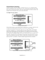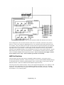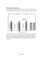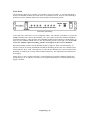
1
SMARTS BROADCAST SYSTEMS Engineering & Installation Manual Copyright SMARTS Broadcast Systems, 1995 UPDATED 7-30-98 Engineering - 1 OVERVIEW 5 DIGITAL SAMPLE OF ANALOG WAVEFORM. 6 TYPES OF SMARTCASTER AUTOMATION 7 Satellite Automation 7 Compact Disc Automation 8 Music on Hard Drive 8 SMARTCASTER Notes No Tone-Decoding Equipment 8 8 Locating the SMARTCASTER 9 SATELLITE AUTOMATION 10 Control Wiring Example for Satellite Control Wiring. 10 11 Satellite Audio 12 Local Audio 12 End of Message Relay Unattended Record Relay Relay 6 used to route Unattended Record source to SMARTCASTER inputs. 13 13 14 37- Pin Connector 14 Jock-In-the-Box CD Automation System 15 CD Audio Wiring Summing Box for CD Audio Ground Strap CD Control Lines - Pioneer Consumer Decks Comm Cable Between CD Server and SMARTCASTER Communciations Cable between CD CONTROLLER and SMARTCASTER. Professional CD Players 16 17 17 17 18 19 19 ULTIMATION--MUSIC ON HARD DRIVE Installation Network Switching Unattended Record 20 20 20 21 Engineering - 2 GENERATION 2000 21 Installation of LAN cable Rebooting with Generation 2000 SMARTCASTER Nodes Simultaneous Playback & Record Node Production Node Traffic Node SmartSwitch Node dBX 140 Impedance Matching Boxes Mounting Connections 21 23 23 23 23 23 24 24 24 24 MONAURAL SIMULTANEOUS PLAYBACK AND RECORD Unbalanced Consoles Setting Levels 26 26 27 INSTALLATION OF DBX 1024 BUFFER AMPLIFIER 28 Mounting 28 Connections Pin 1 Switch Buffer Mode On/Off Switch Setting Levels 28 31 31 32 Simple Network Switching 2x1 Simple Network Switcher 33 33 5x1 Network Switcher 35 AMX 8x4 Switcher 36 Ribbon Cable Connections Output Wiring Input wiring SMARTCASTER Air Out Connection to 8x4 Switcher Audition Channel of Control Board through 8x4 Switcher SmartTouch through the 8x4 Switcher Remote Record audio through the 8x4 Switcher 37 38 39 39 40 40 40 Digital Inputs for Relay Closures Audio Level Adjustment & Operation 41 42 Keystrokes to route AMX Switcher Channels 43 AMX 8x4 Harness Card (In Detail) Isobar Line Filter UPS Power Supply Drive Storage Time Optimizing the Hard Drive 43 45 45 45 45 Defrag Instructions 46 Engineering - 3 Remote Record Terminal for Production Comm Cable between the Remote Terminal and main SMARTCASTER Audio Lines from Production to SMARTCASTER Sometimes Not Just Production... AUDIO CARD DESCRIPTIONS 46 46 46 46 48 VP-635 SX-8/SX-10 SX-3 SX-12/SX-12a SX-7 SX-20 SX-22 100D & ACE Pro 48 48 48 48 49 49 49 50 AUDIOPORT INSTALLATION INSTRUCTIONS 51 SMARTTOUCH 51 SETTING THE SECURITY CODE 51 SMART TOUCH INSTALLATION 53 WATCHDOG: 57 Test of Installation 60 MODEMS WITH PC ANYWHERE ™ 60 SILENCE SENSE ALARM 61 MUSIC ON HARD DRIVE OR SATELLITE AUTOMATION 62 OPTO-ISOLATION 63 COMMUNICATIONS CABLE 64 Engineering - 4 This manual is intended as an overview and step-by-step guide to installing your SMARTCASTER. Since not all units are used in the same way, you may find that there are sections of this manual that apply to your installation, and others that do not. As always, we are ready to help you if you need assistance. Call our toll free number and someone will be placed at your disposal. If, after reading the engineering manual, you have multiple questions, we do ask that you call our support line and set up an appointment to confer with our engineering staff. In addition, we ask that you do not page us after-hours with installation questions unless you have set up an appointment 24 hours in advance. (We need to make sure there is someone with engineering experience ready to answer your questions.) Due to the fast-paced technological advancement of digital audio for broadcasting, it has been found that documentation sometimes lags the latest product releases. (It seemed like every time I was about ready to print this manual, something had changed!) If, after reading this manual, you feel that ‘something just is not right’ with wiring or connections, please feel free to call. There is a good chance that we have the latest manual updates that can be faxed to you. Finally, I would like to ask that the station take part in our ‘Fax & File’ program. Often, an engineer walks into the station, hooks up the system, and then walks out without leaving any documentation behind. We ask that documentation & schematics of the installation be faxed to our office, (800-4980618), and we will file them. At any time, the station, or our technical support personnel, can ask for these documents. This makes for quick technical support service in the event that schematics need to be referenced. In addition, the station now has record of their installation in case the documentation on site is lost. In closing, I would like to thank all of the broadcast engineers I have dealt with over the past few years. Each of you has given me many ideas and suggestions for this manual. Of course, I welcome any suggestions you might have for the next manual! Sincerely, Dane Roach Technical Support Overview “Just what is digital audio?” This might be a question you have been asking yourself throughout the reading of the SMARTCASTER manual. Well, there is a simple explanation. Although the human voice is made up of many complex audio waveforms, we will use the simple waveform as an example: Engineering - 5 Original Simple Analog Waveform. When a computer digitally samples an analog audio wave, it starts at a point in time, say zero seconds, and reads the value of the audio at that point. Now, it moves on, to the next point in time, say one second, and reads this value of audio. Each time the computer does this, it is “sampling” the audio waveform. Every sample is stored on the hard drive of the SMARTCASTER: Digital Sample of Analog Waveform. Now, to play back the audio, the computer essentially plays that childhood game - Dot to Dot. To fill in the gaps, it draws straight lines between each sample. Of course, when samples are done one second apart, the digital recreation of the analog audio signal is not a very good resemblance. (See below.) However, when the samples are done 32,000 times every second, the quality of the sound is excellent. Digital Recreation of Analog Waveform. Most importantly, since these digital values of the analog waveform are stored numerically, the audio sounds exactly the same every time it is played. There is no degradation of the audio - no matter how many times it plays over the air. Engineering - 6 Types of SMARTCASTER Automation There are several ways to use a SMARTCASTER to automate a radio station. “Ultimation”, (Music on Hard Drive), Jock-In-the-Box, (Compact Disc), and Satellite are the three basic types of digital automation around today. Often, these can be combined. For example, it is not unusual for a station to combine a satellite news feed, a satellite talk show feed, and Music on Hard Drive for regular station programming. Satellite Automation In this type of automation, the SMARTCASTER is slaved to the commands of one or more satellite Networks. The satellite service feeds the normal station programming through the satellite downlink. However, the satellite service also “tells” the SMARTCASTER when to play commercials, liners, Audio Switcher ID’s, etc. via relay closures. The SMARTCASTER then plays back, from the hard drive, previously recorded local material. In many satellite automation situations, it is not unusual to have more than one satellite feed. In these cases, the SMARTCASTER can be wired with Network switching devices to switch between the different satellite feeds on a timed basis. Engineering - 7 Compact Disc Automation Many stations opt to automate with compact disc type automation. Instead of a satellite service determining what music goes over the air, the local station can develop its own personal type of music format. In this situation, the SMARTCASTER uses a CD controller computer to “talk” to the various CD decks. In addition, the SMARTCASTER can play back previously recorded commercials, weather bits, liners, jingles, etc. In cases where the station might combine both a Network feed and compact disc originated music, some sort of Network switching device is required. Music on Hard Drive Instead of using compact discs, many stations are recording all of their music to the SMARTCASTER’S hard drive. Combined with commercials, liners, jock intro’s and outro’s, Music On Hard Drive provides total local station automation from a small chassis. Again, if combined with one or more Network satellite feeds, some sort of Network switching device is required. SMARTCASTER Notes The SMARTCASTER is built around a PC computer. However, the PC is simply the first building block of a very complex technical system that allows the unit to produce broadcast quality audio. For starters, the unit has a highly specialized circuit card inside that is really another computer, housed within the main PC computer. This computer, called the audio card, has the responsibility of converting the audio to a string of digits, compressing the digits to a set of manageable numbers, then passing the data to the host PC for storage on the hard drive. On playback, the same thing occurs in reverse, with the host PC passing the data to the audio computer, the computer re-expanding the stream of digits to the full size, then recreating the audio wave to mimic the original analog signal. (See previous discussion on “What is digital audio?”) Because the unit is really two computers in one, there are two separate and distinct programs that run the unit. The programs for the audio computer are called, “Audio Drivers” and give the instructions to the audio card on how to record audio, whether it is stereo or monaural, and what frequency response is needed. The remainder of the software is used to control the main PC computer, to tell the inner computer what audio files to play, when to play them, detect satellite commands, and perform other functions that interface to the outside world. Because of this computer-in-a-computer concept, the SMARTCASTER should not be considered to be just like any other PC. It often can exhibit different characteristics. This makes it important that no other software be placed into the machine! Despite the fact that the SMARTCASTER is more than a computer, from an operator’s perspective, it works almost like any other computer in your office. If you are familiar with PC computers used for more conventional tasks such as logging, traffic, word processing, etc.; you may find that much of that knowledge will come in handy when you are running a SMARTCASTER. If you are just starting to learn computers, you might find it helpful to pick up a copy of any of the beginning computer operator’s books that are widely available. However, you can always check with us on any questions you might have. No Tone-Decoding Equipment To control automation equipment, a satellite service often fires a tone down the satellite link. These might be DTMF, 25/35 Hz, etc. At the station, some type of decoding equipment is needed to detect these tones, and fire a relay closure. SMARTS Broadcast Systems does not manufacture, nor include, any type of tone decoding equipment for satellite feeds. These need to be purchased from an another source. The Engineering - 8 SMARTCASTER is then wired to these relay closures in order to accept commands from a satellite service. It is very important that the SMARTCASTER be wired only to the dry relay contacts of the satellite receiver, and that these contacts never be wired to cart machines, or any other piece of equipment! If the SMARTCASTER is replacing an existing automation machine, take care not to wire the system with the cart machines or other equipment in parallel. If it is absolutely necessary, contact SMARTS for information on isolating these devices from the SMARTCASTER. One more warning Damage due to improper hookup is not covered by the warranty. If you have ANY questions, please call the toll-free support line. Locating the SMARTCASTER The location of the SMARTCASTER needs to be determined by three factors: the way the radio station is operated, accessibility to the unit, and the defense against any extraneous signals that might introduce noise in the system. If the station is on satellite virtually all the time, it may be best to place the computer in the production room. The unit can be wired to that satellite receiver, yet be in a convenient location for production purposes. The disadvantage to this arrangement is that it makes it virtually impossible to use the unit in a “live assist” mode, without adding a remote terminal to the system. If the station is live for a portion of the day, and the computer may be intended for live assist, the best location is in the control room. We suggest the unit be located next to the control board, in the position usually occupied by cart machines, and fed from either a dedicated cart, reel to reel, or the audition side of the control board. With a Remote Production Terminal, life is made easier. The additional computer can be placed in the production room, and the SMARTCASTER can be located in the control room. The third consideration is extraneous signals. The SMARTCASTER has worked in extreme fields with very little problems. However, we have discovered that very close proximity to composite STL transmitters and Optimod processors can introduce noise in the system. Simply relocating the unit a few feet away from the noise source eliminates the problem. To keep RF problems to a minimum, ALL CABLES IN AND OUT OF THE UNIT SHOULD BE SHIELDED, WITH THE SHIELD GROUNDED AT ONE END. This is true of both the audio lines and the control lines. Without Opto-Isolation, the trigger voltage on the SMARTCASTER control lines is only about one volt. Any small transient voltage, exceeding the trigger voltage of the unit, introduced into the control lines will cause a Break or Function to misfire. It can also be advantageous to Ground the SMARTCASTER chassis to station Ground. It is VERY IMPORTANT THAT THE SMARTCASTER BE WIRED ONLY TO THE DRY RELAY CONTACTS OF THE SATELLITE RECEIVER, AND THAT THESE CONTACTS NEVER BE WIRED TO CART MACHINES OR ANY OTHER PIECE OF EQUIPMENT. If the SMARTCASTER is wired for Opto-Isolation, the satellite contacts will switch a twelve volt power supply as opposed to the dry contacts. If the SMARTCASTER is replacing an existing automation machine, take care not to wire the system with the cart machines or other equipment in parallel. Engineering - 9 Satellite Automation Satellite control input and output, and satellite audio input and output to and from the SMARTCASTER are all accomplished through either a 37- pin D-connector located at the rear of the unit, or an Optional Breakout, (fan-out), card. A diagram of this 37- pin connector is included at the end of this section. If the system purchased contains an 8x4 Audio Switcher, please scan through this documentation, and then refer to the AMX 8x4 Switcher section later in this manual. Installation of an 8x4 Switcher for satellite automation is different from most SMARTCASTERS. Control Wiring The control wiring allows the SMARTCASTER to determine when a Local Break is to occur or if a jingle, Audio Switcher ID, etc., needs to be fired. Control flows from the satellite receiver to specific digital inputs of the SMARTCASTER. These digital inputs, located at the 37- pin connector, read the relay closures from the satellite receiver. There are eight of these digital inputs, labeled DI 0 through DI 7. Digital Input 0 is used for Local Breaks, (commercials), and Digital Inputs 1 through 6 are used for Audio Switcher ID’s, jingles, etc. To understand the wiring of the control circuits, we recommend that the installing engineer become more familiar with the concepts of spot files and Function files. (Found in the Operations section of the manual.) Briefly, spot files always mute the Network while they are being played, and are fired from Digital Input 0 of the SMARTCASTER. Functions, on the other hand, are fired from Digital Inputs 1 through 7, and do not mute the Network audio while they play. These Functions play Audio Switcher ID’s, jingles, magic calls, etc. For example, to hook up the Local Break closure from the satellite receiver, Digital Input 0 on the 37- pin connector is used. For an Opto-Isolated unit, (see explanation on Opto-Isolation), the unit fires a Local Break if the positive lead of a 12 Volt DC power supply is connected to pin 12 of the 37- pin connector, (Digital Input High #0), and the common lead is connected to pin 30 of the 37- pin connector, (Digital Input Low #0). (Note: All units, not using the 8x4 Switcher, have been shipped in the opto isolated mode since about 1991.) A 12 volt power supply is provided with the unit. Applying twelve volts across the next Digital Input, fires Function 0 of the SMARTCASTER. Digital Input 2 fires Function 1, etc... On the other hand, in the rare event that the 37 pin connector is not optoisolated, a simple short across the contacts of the Digital Inputs fires the Break. What is heard when the various Functions are fired is dependent on two things: the wiring of the satellite receiver relays to the unit, and secondly, what is recorded for that Function. For detailed instructions on the recording and rotation of Functions, see the Function section of this manual. Engineering - 10 In the example below, a typical satellite receiver has been wired to the 37 pin connector in an optoisolated mode: Example for Satellite Control Wiring. Notice that the two Local Break closures are wired together. With the SMARTCASTER, all Local Break closures should be tied together. Programming within the SMARTCASTER allows for different Break lengths, times, etc. . Engineering - 11 Satellite Audio Satellite Network audio is essentially unprocessed by the SMARTCASTER, but it is switched by relays in order to mute audio during a local commercial Break. For systems with just one satellite service, wire the satellite audio from the satellite receiver, through the four muting relays located on the 37 pin connector, and then back to the control board or mixer. (Note: The SMARTCASTER needs two inputs on the console: One for satellite audio, and a second for local audio from the hard drive. The mixing and matching of levels between these two audio feeds is done at the console or through an external mixer.) Satellite Audio Wiring for 37 Pin Connector For systems using more than one satellite service, some type of Network switching is needed. Refer to the appropriate sections of this manual for the station’s type of switching needs. Note that some switching devices still use the muting relays to mute the output of the Switcher. Others take care of muting internally during Local Breaks. Local Audio Finally, the last type of wiring is local audio. This is audio from the hard drive of the SMARTCASTER itself. The local audio inputs and outputs are the RCA unbalanced connectors or dB connectors on the rear of the unit. (Some SMARTCASTERS use the AudioPort or other internal audio cards for digital audio. Refer to either AUDIO CARD DESCRIPTION or AUDIOPORT Installation for further documenation on connectors.) Connections to and from the SMARTCASTER may be routed through a dBX impedance matchine device. Please refer to the section on the dBX AUDIOI PROCESSOR for correct wiring. Important Note: While most broadcast equipment utilizes the left channel for monaural Operations, the SMARTCASTER, in a monaural mode, uses the right channel. If dBX impedance matching device(s) are not used, simply take the output of the SMARTCASTER, and wire it to a second input on the console. Adjust the gain at the board to match satellite audio levels. Next, wire the production source into the input of the SMARTCASTER. This can be the audition channel of the control board, the program channel of a production board, or the output of a dedicated recording source. For SMARTCASTERS with the Simultaneous Playback and Record Option, there are two outputs on the SMARTCASTER. The output labeled, ‘AIR’ should be wired as described above. This output plays the commercials and Functions over the air as commanded by the satellite service. The output labeled, ‘AUDITION’, should be wired to a third input. This output is used to audition back any material recorded into the SMARTCASTER. Of course, with Simultaneous Playback and Record, Engineering - 12 you may audition one audio cut in cue while playing back another audio cut over the air. It is recommended that the ‘AUDITION’ output be wired into the console - not directly into some cue speakers. If wired into the board, the broadcaster is capable of dubbing spots from the SMARTCASTER to an alternative media source. End of Message Relay An End of Message, (EOM), relay closure is provided on the SMARTCASTER. This closure occurs at the end of the last spot played in a Local Break. The EOM closure is sometimes used in situations where the SMARTCASTER is “slaved” to another automation system. This relay closure can be accessed from pins 10 and 11 on the 37- pin connector. SMARTCASTERS with Simultaneous Playback and Record have this feature turned off. If the EOM relay closure needs to be enabled, contact SMARTS Broadcast Systems or refer to the Setups Appendix in this manual. In SatPak based systems, this feature is shipped in the “on” position. However, if relay 7 is needed for other purposes, contact SMARTS to turn the feature off. Unattended Record Relay A latching relay closure during Unattended Recording is also provided on the SMARTCASTER. This relay is closed for the duration of an Unattended Record. For example, it could be utilized to mute the output audio for systems without the Simultaneous Playback and Record Option. In this manner, the audio being recorded would not be played on the air. Secondly, the relay could be used to pull in a different audio source into the audio inputs of the SMARTCASTER. For example, the audition side of the console could be the normal input to the SMARTCASTER, but during Unattended Recording sessions, relay 6 could fire a four-pole, double throw relay to route in a Brownfield news report. Note: Any relays wired to the SMARTCASTER should be diode protected! (See example below.) Engineering - 13 Relay 6 used to route Unattended Record source to SMARTCASTER inputs. 37- Pin Connector A complete diagram of the 37 pin connector is provided. It is suggested that the engineer make wiring notations on this page for future reference. Engineering - 14 Jock-In-the-Box CD Automation System (NOTE: AS OF THIS WRITING –JULY, 1998 – WE ARE NO LONGER SELLING JIB SYSTEMS) The Jock-In-the-Box CD automation system requires some change of wiring from conventional satellite automation systems. With CD automation, comes the advent of dual processing. The main SMARTCASTER computer is the brain of the entire system and also stores all the digital audio recorded on the hard drive. A CD controller computer is used to “talk” with the CD players in order to cue, play, and stop songs. (This computer does not need a keyboard or monitor.) The CD controller alleviates the processor time needed to control and monitor CD players from the main SMARTCASTER. This provides for a very reliable system. Often, the CD automation systems are also sold with a Remote Production Unit. This unit allows the station to record spots, PSA’s, etc. from the production room. (The computer also comes in handy for any playlist generation programs used in conjunction with the CD system.) Engineering - 15 At this point in time, the Jock-In-the-Box is capable of automating the Pioneer PDM-502 and the PDTM4 consumer decks. (The 502 is the 6 CD player, and the TM series holds 18 discs.) The system is also compatible with the Pioneer CAC-V180M and CAV3200 professional decks. Interfacing the professional decks is a bit different than interfacing the consumer decks. Coverage of both types of installation will follow later in this section. The first step in any CD installation is to place all of the CD decks and the CD server at its final resting point. The CD server and most CD decks are rack-mountable with the aid of rack shelves. In any event, please be sure the area where the decks and controller are installed is well ventilated and kept close to room temperature. Note: The CD controller computer should be placed as close to the CD decks as possible. The wire runs between the CD server and the CD decks should be kept as short as possible. CD Audio Wiring All audio lines from the CD players must be routed to the CD summing box. (See below.) Engineering - 16 Summing Box for CD Audio Please try to keep these unbalanced lines away from AC power lines as much as possible. The audio output from the summing box is then routed to the unbalanced inputs of the dBX Buffer Amplifier. The balanced outputs are then connected to an input on the control board. Level adjustments for the CD audio are made at the Buffer Amp. (If this system contains an 8x4 Switcher, the output of the dBX Buffer Amp should be connected to an input on the 8x4 Switcher instead of a input on the control board.) Ground Strap It is very important that the commercial type CD players be Grounded to the chassis of the CD server. If this common Ground is not present, the CD players cannot function correctly. Please wire a Ground strap between the chassis of every commercial type CD player and the chassis of the CD server. (The screw next to the fan on the back of the CD server provides a very convenient tie point for the strap.) CD Control Lines - Pioneer Consumer Decks Two 20- pin Breakout boards with screw terminals have been provided for connection from the CD server to the CD decks. The first board, for possible decks 1-16, should be connected, via ribbon cable, to the top 20- pin connector on the back of the CD server unit. The second board should be connected to the top 20pin connector located on the surface of the controller card located inside the unit. (To access this card, simply remove the top of the CD server. The card is standing vertically inside the chassis. With the power off, remove this card, and plug the ribbon cable into the TOP connector, CN3) The second board is be used to control any possible decks numbered between 17 and 32. Engineering - 17 PCL 720 CARD (TTL I/O CARD) Diagram of digital I/O card for CD control. Next, take each individual control line from the Breakout cards and connect it to “Control In” of the appropriate CD deck. If one of the cables has come loose from the Breakout card, refer to the table below for connection information. All shields of the control cable should be connected to either pin 17 or 18 on the Breakout card, (GND). The tips should be connected as follows: Deck 1 - 16 : Pins 1 - 16 of the first card. Deck 17-32 : Pins 1-16 of second card. Comm Cable Between CD Server and SMARTCASTER An RS-232 cable must be connected between the CD Server and the main SMARTCASTER unit. This allows the SMARTCASTER to “talk” to the CD Server in order to set up, play, and stop the CD decks. A communications cable, (Comm Cable), is provided by SMARTS. One end should be connected to Com 1 of the CD Server, (9 pin male connection). The other end should be connected to Com 3 of the SMARTCASTER main unit. Com 3 is also a 9 pin male connection. In the event the current cable is somehow damaged, it is simple to wire a new one. The table on the next page provides a schematic for wiring either 9 pin or 25 pin connectors to a Comm Cable. DCD, DTR, DSR, and CTS must all be jumpered together. Rx and Tx on one end of the cable must be crossed with Rx and Tx on the other end. (In other words, Rx is connected to Tx of the other computer, and vice versa.) This same cable is also used to connect the Remote Record unit with the main SMARTCASTER. For more information, please refer to the section on COMMUNICATIONS CABLE. Engineering - 18 WIRING DIAGRAMS FOR COMMUNICATIONS CABLING Communciations Cable between CD CONTROLLER and SMARTCASTER. NOTE: While Com port connections are fairly standard, we may have to change things in the event that a modem is present in the SMARTCASTER. If the SMARTCASTER does contain a modem, please call for more information on connecting Comm Cables. Professional CD Players Please call SMARTS Broadcast Systems for information on the connection of these players. We have the most up to date information on installation of the professional decks. Engineering - 19 Ultimation--Music on Hard Drive From the beginning, there has always been digital automation for those using a satellite format. However, others with specialty, “niche” formats or those who simply wanted their own station “sound”, were left in the cold. After satellite automation was conquered, SMARTS Broadcast Systems turned to the Jock-Inthe-Box CD automation system for this market. Later, as hard drive prices began to drop, and hard drive sizes increased, it began to make sense to place all of the music for a station on the hard drive. This automation system, with the entire station library of music, commercials, and jingles, fits inside a small box that can be placed under a desk. Any piece of digital audio is instantly accessible. Installation By itself, the Music on Hard Drive system is one of the easiest systems to install for a station engineer. The real task comes when all the music must be recorded on the system, and all music information must be logged into the Music Mastertm playlist generation program. Simply connect the audio as ‘Local Audio’ as directed in the Satellite Automation section of this manual. The Air connection should be wired to an input on the console. The Audition connection should be wired to a second input on the console. Finally, the production source should be connected to the Input connection of the SMARTCASTER. dBX products may be used as an interface between the console and the SMARTCASTER. (Consult this manual for the documentation of these products.) Network Switching Often, in conjunction with music from the hard drive, the broadcaster also wishes to switch one or more Networks directly to air. For example, music might play from the hard drive most of the hour, but at the top, the automation needs to switch to a news feed. To direct a satellite feed to air, some sort of switching device is required. Consult the sections on SIMPLE NETWORK SWITCHING or AMX 8x4 SWITCHER to install these devices. With the 2x1 and 5x1 Switchers, leave one input free. This ‘silent’ input should be switched on whenever music is playing from the hard drive. This prevents a Network from getting on the air at inappropriate times when Stops, Pauses, etc. are programmed into the system. Engineering - 20 Unattended Record Often, with Ultimation, a station simply wishes to air a news feed at the top of the hour. If the news is pre-recorded with the Unattended Record feature of the SMARTCASTER, no switching device is needed. Consult ‘UNATTENDED RECORD RELAY’ of the OPERATIONS section of this manual for further information. Generation 2000 The Generation 2000 SMARTCASTER line simplifies installation between several SMARTCASTERS. Using a digital LAN Network, several SMARTCASTERS can be linked together in order to share hard drives. Any audio recorded on one SMARTCASTER is instantly accessible to other SMARTCASTERS on the Network. No analog or digital dub is necessary. Using Generation 2000 technology, any system can play audio from any hard drive on the Network. Generation 2000 can be used for any combination of satellite, CD, or music on hard drive automation. Installation of LAN cable Installation of a Generation 2000 system is similar to most SMARTCASTER systems. However, before beginning anything else, the LAN Network must be up and running. To do so, RG58-U coaxial cable needs to be run from computer node to computer node in a daisy-chain fashion. Generation 2000 wiring with RG58-U coaxial cable. At each SMARTCASTER terminal, there should be a male BNC connector. Supplied with each terminal should be a BNC T-Connector. The leg of the T-Connector should be female, and each end should be male. Connect the female leg of the T-Connector to the BNC connector on the SMARTCASTER. After crimping a female connector on the RG58-U cable, connect it to one male connection of the T-Connector. The other male connection of the T-connector should be connected to one of two possibilities: (1) If this node is to be connected to another node further down the line, connect the next run of RG58-U. (2) If this Engineering - 21 is the last node in the line, connect one of the supplied 50 ohm terminators. Engineering - 22 (Install LAN, cont..) It is very important that the LAN cable be run as a ‘line’ in a daisy-chain fashion instead of the ‘hub & spoke’ concept. The ‘hub & spoke’ wiring configuration will not work with this LAN Network. In addition, it is important that only RG58-U be used as cable, and that each end of the line is capped with 50 ohm terminators. Once the LAN is connected, all of the computers may be turned on. As soon as all of the computers are on-line, the Lantastic software will initiate the Networking software. Rebooting with Generation 2000 In the advent that a computer on the LAN Network needs to be rebooted, care must be taken. There are two reboot scenarios in which a computer can be powered down, and back on. In the first scenario, one computer needs to be reset, and all other computers on the Network are up and running. In this case, it is safe to exit this computer out to the main SMARTCASTER menu, and reboot. The other computers on the Network know when the rebooted computer is back on-line. In the second scenario, computer A needs to be reset, but a second computer, (computer B), on the Network is currently powered down. It is ok to reset computer A when computer B is powered down, but when computer B is powered back up and running, please reboot computer A. While computer B was off, computer A booted up and checked to see what computers were on the Network. Computer B was not on the Network, and hence computer A did not know that it should be on the net. Therefore, it does not bother checking later to see if computer B ever comes back on-line. SMARTCASTER Nodes Each node of the Network can be configured in different ways depending on the type of system purchased. Each audio node uses the ACE Apt-X audio card. (A description of connections for this audio card can be found in the section labeled, ‘AUDIO CARD CONNECTIONS’ found in this engineering manual.) After the Network is up and running, installation continues like any other SMARTCASTER described in this manual. Simultaneous Playback & Record Node Generally purchased for the control room of the station. This node has the capability to Record or Audition while playing audio on the air. Like most Simultaneous Playback & Record systems, it has one audio input, and two audio outputs: Audition and Air. This is very useful for doing Unattended Recordings while other production nodes on the Network are in use by station personnel. A Playback Only Node is often purchased for use in the control room. This node has only the capacity to Playback audio on the air. It cannot Record audio. It may Audition audio, but Playback to air must be halted. Obviously, with this system, there must be another production node on the Network. For audio connections, it simply has one audio output. Production Node This unit has the capability to Record and Audition. However, it cannot perform Simultaneous Playback and Record. This unit is usually placed in the production room. It has one audio input and one audio output. Traffic Node By installing a Network card in an MS-DOS, IBM Compatible computer, any traffic & billing system can be added to the Network. This makes for efficient downloads of the daily log to the SMARTCASTERS on Engineering - 23 the Network. In addition, any Verification Logs can be retrieved from the units. If an existing unit is being upgraded, please contact our Support Department in order to install the card and Lantastic software. SmartSwitch Node This computer node can handle any Network switching for multiple radio stations throughout the Network. Audio can be routed for Unattended Records or live air feeds to virtually any point at the installation site. In addition, transponder switching can be accomplished via relay closures. Please contact the Support Department for the latest, up-to-date information on this product. dBX 140 Impedance Matching Boxes The dBX Option provides two important functions for proper SMARTCASTER operation. First, the unit “compands” or smashes the audio entering the computer, and reduces the dynamic range at a ratio of about 2 to 1. The encoder of the dBX performs this operation, while the decoder restores the audio from the computer back to its original dynamic range. Second, the dBX unit(s) provides a convenient way to match impedance from the high impedance, unbalanced inputs/outputs of the SMARTCASTER to the standard 600 ohm broadcast circuitry. In cases where the SMARTCASTER has stereo Simultaneous Playback and Record, two dBX units are needed. This is because a Simultaneous unit has two outputs - “Audition” and “Air.” (Thus, one can listen to a commercial just Recorded via Audition while other spots are going over the air via the Air output.) With two stereo outputs, two stereo dBX decoders are needed. As a result, the second dBX unit is just used for decoding only. Mounting The dBX unit(s) may be rack mounted using the mounting kit that is included, or it may simply be set in any convenient location near the SMARTCASTER. (Refer to the dBX manual for instructions on the rack mounting kit.) Note however that since the SMARTCASTER connections to the dBX unit are unbalanced, the leads MUST BE AS SHORT AS POSSIBLE! Please take care that the unit is not near any sources of RF that might interfere with its operation. Connections The plugs used with the dBX units are connected using the stereo “tip-ring-sleeve” type 1/4 inch plug. Do not use the monaural version of this plug that only has a tip and a sleeve connection! (This plug is the secret to proper impedance matching.) Diagrams of the connections between the control board, dBX(s), and the SMARTCASTER are shown in the following figures. On the back of the dBX units are four sets of A and B channel connections labeled “From Console,” “To Console,” “From Tape Rec.,” and “To Tape Rec.” Simply make the connections as shown below with the correct type of 1/4” plug. A diagram for plug-types is shown following the dBX wiring diagrams. For example, connection should be made between From Console and the output of the control board with a “Type A” plug. Engineering - 24 dBX Wiring for SMARTCASTER without Simultaneous Playback and Record. dBX Wiring for SMARTCASTER with Simultaneous Playback and Record. Engineering - 25 Monaural Simultaneous Playback and Record For SMARTCASTERS equipped with the monaural version of Simultaneous Playback and Record, the dBX wiring can be accomplished with one dBX - even with two outputs. Use channel A of the dBX for audio from the console, through the dBX, and into the SMARTCASTER. Also use channel A for Audition audio coming from the SMARTCASTER, through the dBX, and into the Audition input on the console. Finally, use channel B for the Air audio from the the SMARTCASTER, through the dBX, and going into the console. dBX plug types for impedance matching. Unbalanced Consoles If the console has either unbalanced inputs or outputs, some modification is needed in wiring. For unbalanced inputs, simply replace type ‘A’ plug connected to the “To Console” connection of the dBX with a type ‘B’ plug. For unbalanced outputs, replace the type ‘A’ plug connected to the “From Console” connection with a type ‘C’ plug. Engineering - 26 Setting Levels Setting the input levels involves synchronization of the VU meters at the source, (usually the production console or the audition bus of the Air console), with the SMARTCASTER input. To set the input gain, use complex audio modulation such as music, speech, or a spot, and set the gain so that the meters on the board read correctly. Next, engage all of the buttons of the front of the dBX units. Go into the Record Screen of the SMARTCASTER. After setting up a sample test spot to Record, (refer to the Operations section of the manual for information on Recording), adjust the DIGITAL INPUT LEVEL to about halfway. Now adjust the REC pots on dBX #1 to the desired level. Do not let the word “OVERLOAD” appear very often on the SMARTCASTER Record Screen. Any audio recorded while this word appears is distorted. To set the output gain, open the channel on the console that carries the audio from the SMARTCASTER to a normal operating position for the board. Next, start playing back a properly recorded spot in the SMARTCASTER. (Note: In SMARTCASTERS using Simultaneous Playback and Record, a spot should be played in live assist to adjust the output gain for the air channel, and a spot should be auditioned in the Record Screen to adjust the output gain for the SMARTCASTER’s audition channel.) Adjust the trim pots for the desired playback level. If wiring a Sat-Pac unit that uses the external AudioPort, there is not any level information on the Screen. Setting levels with the Sat-Pac can best be done by recording an input signal at high level, and auditioning it. If the audio is distorted, lower the input signal via the trim pots on the dBX, and try again until the audio is not distorted. NOTE: Please make sure that all of the blue buttons on the dBX are engaged. If the buttons are not engaged, all dBX processing functions are bypassed - resulting in a loss of companding capabilities and proper impedance matching. NOTE: In most cases, the audio recorded on the SMARTCASTER at the factory was done without a dBX. As a result, any of this audio sounds muddy when played back through a dBX. Engineering - 27 Installation of dBX 1024 Buffer Amplifier The dBX 1024 Buffer Amplifier is used as an impedance matching device between SMARTCASTERS with unbalanced input and outputs, and the console. Similar to a dBX 140, but without companding capabilities, it is often used with systems containing high quality audio cards. The dBX is also used to match levels and provide balanced inputs and outputs. Like the dBX 140 unit, the Buffer Amplifier can match both an unbalanced Hi-Z input to a balanced 600 ohm output and match a balanced 600 ohm input to an unbalanced Hi-Z output. In cases where the SMARTCASTER has stereo Simultaneous Playback and Record, two dBX units are needed. This is because a Simultaneous unit has two outputs - “Audition” and “Air.” (Thus, one can listen to a commercial just recorded via Audition while other spots are going over the air via the Air output.) With two stereo outputs, two stereo dBX decoders are needed. As a result, the second dBX unit is just used for output only. Mounting The dBX unit(s) may be rack mounted using the mounting kit that is included, or it may simply be set in any convenient location near the SMARTCASTER. (Refer to the dBX manual for instructions on the rack mounting kit.) Note however that since the SMARTCASTER connections to the dBX unit are unbalanced, the leads MUST BE AS SHORT AS POSSIBLE! Please take care that the unit is not near any sources of RF that might interfere with its operation. Connections Rear view of dBX 1024 The dBX 1024 uses locking XLR connectors for balanced, 600 ohm connections, and RCA phono jacks for unbalanced HI-Z connections. The XLR jacks are wired pin 2 HOT (+), pin 3 COLD (-), and pin 1 chassis GROUND. Since the RCA connects are unbalanced, the outside conductor is Ground, and the remaining conductor is HOT (+). Depending on the type of system to be installed, there are several configurations for wiring the Buffer Amplifier. Simply pick the appropriate diagram below and wire accordingly: Engineering - 28 dBX 1024 FOR SIMULTANEOUS SYSTEMS dBX 1024 wiring for systems without Simultaneous Playback & Record. SMARTCASTERS without Simultaneous Playback & Record only have one output and one input. Therefore they need just one dBX unit. For stereo, it is suggested that the left channel be routed through channel 1 of the dBX. Right channel should be routed through channel 2. For monaural systems, simply use channel 1, and leave channel 2 free. Engineering - 29 dBX 1024 FOR SIMULTANEOUS MONAURAL SYSTEM dBX 1024 wiring for Simultaneous Monaural System. Systems that have Simultaneous Playback & Record have one input, and two outputs: Audition and Air. Since the dBX 1024 has two independent channels, monaural systems with Simultaneous Playback & Record can also use one dBX unit. Channel 1 is used to route the Air output and channel 2 is used to route the Audition output. Engineering - 30 dBX 1024 FOR SIMULTANEOUS STEREO SYSTEM dBX 1024 wiring for Simultaneous Stereo System. With a stereo, simultaneous SMARTCASTER, two dBX units are needed. One dBX matches both the Input and Air channels of the SMARTCASTER. The second unit simply matches the Audition output of the SMARTCASTER. (The XLR Input to RCA Output is left free.) Pin 1 Switch This switch internally disconnects the XLR Input pin 1, (both channels), from the 1024 Chassis Ground to eliminate any Ground loop hum problems that may arise. If necessary, an internal jumper on the 1024 can be set to isolate the dBX Circuit Ground from the Chassis Ground if Ground loop hum problems are caused by the SMARTCASTER. Buffer Mode On/Off Switch This rear panel slide switch sets the unit as a Buffer Amplifier for changing unbalanced +4dB signals into balanced form. This switch selects either the RCA (-10dBV) inputs or XLR (+4dBu) inputs to drive the XLR outputs. The switch should be in the OFF position, so that the XLR inputs drive the RCA outputs, (with 11.8dB of attenuation; adjustable +/- 10dB), and the RCA inputs drive the XLR outputs, (with 11.8dB of gain, adjustable +/- 10dB). Engineering - 31 Setting Levels Setting the input levels involves synchronization of the VU meters at the source, (usually the production console or the audition bus of the air console), with the SMARTCASTER input. To set the input gain, use complex audio modulation such as music, speech, or a spot, and set the gain so that the meters on the board read correctly. Go into the Record Screen of the SMARTCASTER. After setting up a sample test spot to record, (refer to the Operations section of the manual for information on recording), adjust the DIGITAL INPUT GAIN to under the ‘G’ in the word GAIN. (The words DIGITAL INPUT GAIN appear on the SMARTCASTER Record Screen. Use these words on the Screen as a reference). Now adjust the IHF pots on dBX #1 to the desired level. Do not let the word “OVERLOAD” appear. Any audio recorded while this word appears is distorted. To set the output gain, open the channel on the console that carries the audio from the SMARTCASTER to a normal operating position for the board. Next, start playing back a properly recorded spot in the SMARTCASTER. (Note: In SMARTCASTERS using Simultaneous Playback and Record, a spot should be played in live assist to adjust the output gain for the air channel, and a spot should be auditioned in the Record Screen to adjust the output gain for the SMARTCASTER’S audition channel.) Adjust the trim pots for the desired playback level. If the SMARTCASTER is a Sat-Pac unit that uses the external AudioPort, there is no level information on the Screen. Setting levels with the Sat-Pac can best be done by recording an input signal at high level, and auditioning it. If the audio is distorted, lower the input signal via the trim pots on the dBX, and try again until the audio is not distorted. Engineering - 32 Simple Network Switching There are several types of Network switching. The simplest version is a 2 in, 1 out Network Switcher based on a latching relay circuit. The next step up is a 5 in, 1 out Switcher, also based on relays. Finally, there is the 8 in, 4 out solid state Switcher. This section explains both the 2x1 and the 5x1 Switcher. For information on the 8x4 Switcher, refer to a later section in this manual. 2x1 Simple Network Switcher 2x1 Simple Network Switcher. The 2x1 Network Switcher is used for simple Network switching needs. For example, a station may want to switch between a typical satellite music Network to a news service at the top of the hour. To install, just run audio lines for the primary satellite service, (Ex: Music Satellite), into the primary audio source, (Terminals 5,6,7,8). Connect the audio lines of the secondary news service, (Ex: News Feed), into the secondary audio source, (again, terminals 5,6,7,8). Finally, run a line from the output to the muting relays of the SMARTCASTER. (On the 37- pin connector, these are 3:L+ 6:L- 9:R+ 22:R-) Next, control lines from SMARTCASTER relays need to be connected to the vertical control strip. (See figure below.) Normally, relay 4 is used to latch the secondary input to the output, and relay 5 is used to release the output back to the primary input. However, if these relays are used, there are ways to utilize other relays on the 37- pin connector. Contact the SMARTS Support Staff for more information. Control and Audio Lines wired to 2x1 Simple Network Switcher Engineering - 33 Finally, there is usually the need to disable the SMARTCASTER from seeing relay closures from the primary audio source while on the secondary audio source, and vica versa. In our example, we would want to keep the SMARTCASTER from seeing, (and playing), a jingle while the news is on the air. In order to do this, the 12 volt line wired in series with the satellite receiver relay closures, can be switched away from the primary, to the secondary, via the switching contacts on pin four of the horizontal strips. (See below.) To prevent closures from one service from being ‘seen’ while second service is on the air. Pins 30 through 37 are the Digital Input Low’s on the 37- pin connector. For the SMARTCASTER to sense a closure, 12 Volts must be placed across the digital input low’s and digital input high’s on the 37pin connector. By routing the 12 volts through the Switcher, the 12 volt line is switched between the two satellite receivers. Engineering - 34 5x1 Network Switcher The 5x1 Network Switcher, while based on relay technology, is wired a bit differently than the 2x1 Switcher. 5x1 Switcher shown with control wiring from SMARTCASTER. The top horizontal strip is the normally closed position for the five different inputs. The second strip is the normally open position for the five different inputs. In almost all cases, audio inputs should be wired to the normally open positions, (the second strip). The first strip should only be used in special cases. The SMARTCASTER , upon command, routes any one of the five inputs to the common output located on the bottom strip. All audio sources that must be switched should be wired into the five different inputs. The output should be wired directly into the satellite pot on the control board. (As with most SMARTCASTER systems, the SMARTCASTER ‘On Air’ audio from the hard drive should be wired into a second input pot on the board. Levels can then be matched at the control board.) Muting of Networks during local commercial Breaks is accomplished through the 5x1 Switcher. Control wiring for the 5x1 Switcher is shown in the figure above. The first five relays located on the 37 pin connector are used to control the Switcher. If , for example, Network 2 is to be on the air, relay 1, (pins 4 & 5), latch and hold. If, at a later time, Network 1 is to be on the air, the SMARTCASTER unlatches relay 1, and latches in relay 0, (pins 1 & 2). Of course, during times that the Networks are to be muted, all five relays are in an unlatched condition. Like the 2x1 Network Switcher, some external wiring must be done in order to prevent the SMARTCASTER from seeing closures from one Network while another is on the air. Engineering - 35 5x1 wiring to prevent closures being sensed by SMARTCASTER from Networks not on the air. In the example above, there are three Networks wired to the 5x1 Switcher, and all have relay closures. Pins 30-37 of the 37 pin connector, (Digital Input Low’s), are connected to the GND connection on the 5x1 Switcher. Next, each satellite receiver has one side of all of its relays bussed together, and connected to its control line on the 5x1 Switcher. Finally, each specific relay is then wired into a specific Digital Input High on the 37 pin connector. In this example, the first satellite receiver has a relay wired as Function 0 on the SMARTCASTER, the second satellite receiver has a relay wired to Function 1, and the third satellite receiver has a relay wired to Function 2. (For information on Functions and Local Breaks, refer to CONTROL WIRING in this engineering manual.) Note: No external 12 Volt supply is needed for the satellite receiver relays! The 5x1 Switcher provides the 12V internally. AMX 8x4 Switcher The 8x4 Switcher provides many features to SMARTCASTER automation - giving it the power to perform multi-Network automation. With the 8x4 Switcher, not only can the SMARTCASTER handle up to 8 Network feeds for recording or playback purposes, but it can also handle 16 relay closures from the different Networks. (More can be added with an additional expansion board.) The wiring of the 8x4 is relatively simple. There are four outputs and eight inputs. Two outputs are used to route any of the eight inputs to air or to the SMARTCASTER record inputs. There are no routing limitations. It is possible to route an input to all four outputs at the same time if necessary. The AMX 8x4 Switcher is a very versatile product. Engineering - 36 Ribbon Cable Connections Three 20-pin flat ribbon cables, one 64-pin flat ribbon cable, and a gold 8x4 Switcher Harness Card, (see below), should be included with the 8x4 Switcher. This card is used to make connections between the SMARTCASTER and the 8x4 Switcher. In addition, all satellite relay closures are wired into this card. AMX 8x4 Switcher Harness On the SMARTCASTER are four 20- pin female connectors, labeled CON 1, CON 2, CON 3, and CON 4. Connect CN 1 to CON 1 with a 20-pin flat ribbon cable. The signals in this cable route inputs to outputs 1 & 2 of the 8x4 Switcher. Next, connect CN 2 with CON 2 on the SMARTCASTER. These signals are used for receiving relay closures from satellite receivers. Now connect CN 3 with CON 3. With this connection, the SMARTCASTER can route inputs to outputs 3 & 4 of the 8x4 Switcher. Finally, connect the 64-pin flat ribbon cable between the AMX Switcher Harness and the back of the AMX Switcher. Engineering - 37 Output Wiring Of the four outputs on the 8x4 Switcher, only two are needed. Output 1 is routed to an input on the console, and output 2 is routed to the record inputs of the SMARTCASTER. 8x4 Switcher output wiring. Unbalanced feeds are connected with the center conductor wired to the ‘+’ terminal, and the shield connected to Ground. The ‘-‘ terminal is not used with unbalanced connections. For balanced connections, the Ground terminal is provided if needed. However, take care not to Ground the shield at both ends of the cable. If the SMARTCASTER is using a dBX, connect output 2 of the 8x4 Switcher through the dBX into the record inputs of the SMARTCASTER. If there is not a dBX, then connect output 2 directly to the record inputs of the SMARTCASTER. Engineering - 38 Input wiring AMX 8x4 Switcher - rear view. Audio inputs can either be balanced or unbalanced. Balanced audio should be connected to the ‘+’ and ‘-‘ terminals. The shield can be connected to the Ground terminal. With unbalanced connections, the ‘hot’ line or center conductor should be connected to the ‘+’ terminal. The shield should then be connected to Ground. The ‘-‘ terminal is not used in the case of unbalanced connections. Input connection for 8x4 Switcher. Try to connect satellite feeds starting with input #1, and working upwards. The upper inputs should be used for special SMARTCASTER connections if possible. SMARTCASTER Air Out Connection to 8x4 Switcher To conserve inputs on the control board, the SMARTCASTER Air output can be mixed with the satellite feeds using the 8x4 Switcher. Simply connect the SMARTCASTER Air output to input 8 of the 8x4 Switcher. If the SMARTCASTER Air output is using a dBX product, connect the Air output to the dBX input, and the dBX output to input 8 of the AMX Switcher. Next, enter the ‘Options Setup’ from the Setup menu, or at the C:> prompt, type OSETUP. Option 16, “ Is SMARTCASTER audio fed through AMX input 8?” should be set to ‘Y’. If it currently set to ‘N’, type 16 and press e. Next, just type Y and e. When this feature is implemented, the SMARTCASTER always leaves input 8 on. Thus, when Local Breaks or Functions are played, the SMARTCASTER plays this audio through input 8. During Local Breaks, the SMARTCASTER turns off inputs 1-7 from output 1 in order to mute any Network feeds. (It does not remove these Networks from any other output in case an Unattended Record is in progress.) Engineering - 39 Audition Channel of Control Board through 8x4 Switcher If the AMX Switcher is to be used for Unattended Recording AND normal studio production, the audition channel of the console must be wired into an input on the 8x4 Switcher. When this feature is enabled, the SMARTCASTER automatically routes the audition channel to the record inputs of the SMARTCASTER when the user enters the Record/Audition Screen. For the sake of keeping a standard throughout SMARTCASTER installations, we recommend that input 7 be used. However, any input can be utilized. (By keeping a standard, our support staff can quickly fix station problems over the phone without having to check Setup configurations.) To enable this Option, choose the Options Setup from the Setup menu, or type OSETUP at the C:> prompt. Option 6, “Default AMX input for recording to SMARTCASTER” should be set to the appropriate input number, (Ex: 7). SmartTouch through the 8x4 Switcher If desired, the SmartTouch can be wired as an input to the 8x4 Switcher. Simply wire System Out to an input on the 8x4 Switcher. To enable the feature, in Options Setup or OSETUP, Option 14, “AMX input for SmartTouch” should be set to the appropriate input number, (Ex: 6). When the user calls the SmartTouch, the SMARTCASTER automatically routes this input to the air during the remote broadcast. Remote Record audio through the 8x4 Switcher If the station has purchased a Remote Record unit, the audio from the production room can be wired as an input to the 8x4 Switcher. Note: The Remote Record unit is not the production unit purchased with the Generation 2000 system. The Remote Record unit is a production console using RS-232 to communicate to the SMARTCASTER. (The Generation 2000 uses a LAN Network.) Simply wire the audio from the production console into an input of the 8x4 Switcher. In the Options Setup or OSETUP, Option 21, “Remote Production AMX input (using PCU)” should be set to the appropriate input, (Ex: 5). Now, whenever someone records audio from the Remote Record unit, the SMARTCASTER automatically routes the appropriate input to output 2 of the AMX Switcher. Engineering - 40 Digital Inputs for Relay Closures All relay connections to the 8x4 Switcher are made via the two terminal strips located at the corner of the 8x4 Harness Card. All connections should be made with dry contact closures. Do not place any voltage supply in series with satellite relay closures!!!! The digital inputs used with the 8x4 Switcher are not Opto-Isolated, and will be seriously damaged if a power supply is placed in series with the relay closures from the satellite receiver! A description of each terminal is shown below: Terminal Strip Description of AMX 8x4 Harness 1 3 5 7 9 11 13 15 17 19 Digital Input Digital Input Digital Input Digital Input Digital Input Digital Input Digital Input Digital Input Ground 5 Volts DC 1 3 5 7 9 11 13 15 2 4 6 8 10 12 14 16 18 20 Digital Input Digital Input Digital Input Digital Input Digital Input Digital Input Digital Input Digital Input Ground Strobe N/A 2 4 6 8 10 12 14 16 To connect a relay closure to the AMX Harness, first ‘bus’ together one side of all relay closures that will be used from all satellite receivers. (Unlike other Switchers, the AMX can distinguish which closures are valid through software.) Connect these Grounds via either terminal 17 or 18. Next, connect the other side of each relay to a digital input terminal. Try to group relays from the same Network together. Engineering - 41 Example relay closure wiring to AMX Harness Board. Again, do not worry about disabling relay closures in the event that one satellite receiver might fire a closure while another satellite feed was on the air. With the AMX 8x4 Switcher, the SMARTCASTER software keeps track of which digital inputs are valid during the time that each Network is on the air. Make sure the SMARTCASTER is setup properly to acknowledge relay closures through the AMX Harness and not the standard relay card. In the ‘Options Setup’, or OSETUP at the C:> prompt, check Option 17, “Detect closures via TTL input instead of relay card”. It should be set to ‘Y’. In addition, to program the SMARTCASTER to see relay closures, refer to Timed Events in the Operations portion of the manual. This section explains how to setup the AMX inputs at different times of the day for each Network. Audio Level Adjustment & Operation Audio adjustments can be made with the trim pots located on the front of the unit. For balanced audio signals operating at unity gain, the pots should be fully counter-clockwise. For lower level, (i.e. unbalanced), inputs, adjust the pots as desired. Front view of the AMX 8x4 Switcher. Adjust levels for the SMARTCASTER record inputs. To do this, some temporary modification needs to be made in ‘Other Options’, (OSETUP from C:> prompt). Option 6, “Default AMX input for recording to the SMARTCASTER” should be set to the channel being adjusted. Next, re-enter the SMARTCASTER program, and go into the Record Screen. At this point, on the Activity Lights, the channel being adjusted should be lit. Try recording a test spot. Levels from the channel being adjusted should appear. Trim the pots so that the word, OVERLOAD does not appear on the Screen. Once all channels are adjusted, do not forget to set Option 6 back to its original setting. Engineering - 42 Theoretically, levels should now be the same for all inputs. However, if a channel through output 1 of the Switcher needs to be checked, go to the main automation Screen of SMARTCASTER. The following keystrokes route different inputs to the appropriate output: Keystrokes to route AMX Switcher Channels Input Input Input Input Input Input Input Input 1 2 3 4 5 6 7 8 Bank 1 Alt-F1 Alt-F2 Alt-F3 Alt-F4 Alt-F5 Alt-F6 Alt-F7 Alt-F8 Bank 2 Alt-F9 Alt-F10 Alt-F11 Alt-F12 Shift-F1 Shift-F2 Shift-F3 Shift-F4 Alt-A Alt-B Alt-C Alt-D Alt-E Cancel Cancel Cancel Cancel Cancel All All All All All Bank 3 Shift-F5 Shift-F6 Shift-F7 Shift-F8 Shift-F9 Shift-F10 Shift-F11 Shift-F12 Bank 4 Ctrl-F5 Ctrl-F6 Ctrl-F7 Ctrl-F8 Ctrl-F9 Ctrl-F10 Ctrl-F11 Ctrl-F12 Bank 1 Bank 2 Bank 3 Bank 4 Banks As each input is turned on or off, the appropriate LED lights on the Channel Activity Meter located on the front of the unit. Remember, if Setup has been told that SMARTCASTER Air output has been wired through input 8, then this light is always on. AMX 8x4 Harness Card (In Detail) Sometimes it is necessary to make modifications to the Harness Card. Details provided from within this section of the documentation should make this possible. However, if traces need to be cut, please contact the SMARTS Support Staff to verify that no damage occurs. To each side of CN 1 and CN 3, are headers for connections. Connectors for these headers can be obtained at any electronic supply house. (Contact SMARTS for ordering information.) These lines are used to route inputs of the AMX Switcher to any of the four outputs. Each output uses eight digital output lines from the SMARTCASTER - one for each audio input. To route an input on the AMX Switcher, the appropriate digital line should be shorted to Ground. CN 1 Engineering - 43 Pin 1 3 5 7 9 11 13 15 17 19 Input Input 1 Input 3 Input 5 Input 7 Input 1 Input 3 Input 5 Input 7 Ground 5 Volts DC Output Output Output Output Output Output Output Output Output Pin 1 1 1 1 2 2 2 2 2 4 6 8 10 12 14 16 18 20 Input Output Input 2 Output Input 4 Output Input 6 Output Input 8 Output Input 2 Output Input 4 Output Input 6 Output Input 8 Output Ground 12 Volts DC 2 4 6 8 10 12 14 16 18 20 Input Output Input 2 Output Input 4 Output Input 6 Output Input 8 Output Input 2 Output Input 4 Output Input 6 Output Input 8 Output Ground 12 Volts DC 1 1 1 1 2 2 2 2 CN 3 Pin 1 3 5 7 9 11 13 15 17 19 Input Input 1 Input 3 Input 5 Input 7 Input 1 Input 3 Input 5 Input 7 Ground 5 Volts DC Output Output Output Output Output Output Output Output Output Pin 3 3 3 3 4 4 4 4 3 3 3 3 4 4 4 4 Routing lines for 8x4 Harness. For example, if input 3 needed to be routed to output 3, then pin 3 on CN 3 should be shorted to either pin 17 or 18 on CN 3. Sometimes, it is desirable for an input to always be on. If an engineer wanted to wire a bank of CD players into the 8x4 Switcher, he or she could simply short the appropriate digital output from the SMARTCASTER to Ground using these connectors. In addition, there are sockets for relays and other circuit modifications located above the terminal strips. These can be used at will for making modifications. Engineering - 44 Isobar Line Filter The Isobar Line Filter is used to protect the system from lightning strikes and line surges. It should be plugged into an AC outlet, and the UPS Power Supply should then be plugged into an outlet on the Isobar Line Filter. DO NOT PLUG ANY PART OF THE SMARTCASTER DIRECTLY INTO AN AC PLUG. UPS Power Supply The UPS (Uninterruptable Power Supply) provides a backup power supply in case a power outage occurs. At the time of an outage, enough power should be stored to allow for, on average, 45 minutes of power to the SMARTCASTER. However, the unit does need time to charge. During the installation of the SMARTCASTER, it might be a good idea to leave this plugged into the Isobar Line Filter. All pieces of the SMARTCASTER that must have backup power should be plugged into the UPS. Examples: Main SMARTCASTER CPU, any external 12V supplies, any switching equipment, etc. Please understand that if the UPS has a large load, it may not be able to provide sufficient time for backup. For example, if there are 24 CD players, a CD server computer, a SMARTCASTER, and an 8x4 Switcher, there is probably too much of a load for one UPS. It might be a good idea to plug all the CD players into a second UPS. Drive Storage Time Unlike a conventional cart system, spots, once recorded, are virtually invisible. Instead of racks of carts mounted on the control room wall, the computer is holding all the data, and it looks just the same whether it is full or empty. Because of this, it is very easy with the SMARTCASTER to simply record, day after day, without paying attention to the remaining drive space. PLEASE DO NOT DO THIS. Set up a housekeeping routine daily to delete any outdated spots, and never let the drive fill up. If it is noticed that the recording process stops before the spot is finished, please do not continue to attempt to record. Delete material before recording further. If the drive is always running full, and nothing can be deleted, please contact us about adding additional drive space. Optimizing the Hard Drive About every month, someone at the station MUST RUN A DISK OPTIMIZATION PROGRAM!!! We recommend either the Compress program in PCTOOLS, Speed Disk in Norton Utilities, Optune from Gazelle Software, or MS-Dos 6.2’s Defrag. At the time of this print, only Optune and Defrag Optimize drives 1.0 Gigabyte and above. (MS-Dos 6.2 is shipped with every SMARTCASTER at this time.) During the life of a SMARTCASTER, the audio files “fragment” into smaller and smaller pieces as new files are placed on the hard drive. As these “pieces” become smaller, it takes the hard drive longer and longer to locate the open space between the audio files. As a result, Functions and spots may fire slow or not at all. In this condition the audio may distort, cut in and out or turn to a loud ‘hash’ sound. ‘Defragmenting’ or ‘Optimizing’ the hard drive is the answer to this problem. The disk Optimizer takes these fragmented pieces of files, and lines them up in a sequential manner. In this manner, the hard drive does not have to work as hard to find the audio files, and is able to play back spots and Functions when needed. Disk optimization does take some time, so it is probably best to perform this operation when the station is off the air or at a time when the SMARTCASTER is not used. Engineering - 45 We cannot emphasize enough how important this operation is to the SMARTCASTER. Please do not neglect this duty. Defrag Instructions To run Defrag, go to the main menu of the SMARTCASTER. Reset the computer. Next, if ‘Optimization’ is on the main menu, select it. Otherwise, press u to get to the C:> prompt, and type: DEFRAG /F and press e Once in the Defrag program, the system asks which drive to Optimize. Highlight the correct drive and press e. Defrag now Optimizes the drive. When finished, the program drops back to the C:> prompt. Reset the SMARTCASTER. Remote Record Terminal for Production All SMARTCASTERS capable of Simultaneous Playback and Record can be equipped with a remote terminal for production. This terminal allows someone in the production room to directly record audio from the production board to the main SMARTCASTER unit. Hookup is simple. Audio lines from either a distribution amp in the production room or from an output channel on the production console need to be run from the production room to the main SMARTCASTER unit. Second, a Comm cable, similar to the one discussed in the Jock-In-the-Box CD automation system, needs to be run from the Remote Record Terminal to the main SMARTCASTER unit. In the event that one production room is feeding two SMARTCASTERS for two different stations in the building, a Comm A/B switch can be installed to switch communication from the Remote Record Terminal to either SMARTCASTER. Comm Cable between the Remote Terminal and main SMARTCASTER The communications between the main SMARTCASTER and the Remote Terminal is performed via an RS-232 line between the two machines. With this line, the two computers can talk similar to the way two computers talk via phone lines and modems. One end of the Comm cable should be connected to Com 1, (9 pin male), port of the Remote Record Terminal. The other end should be connected to Com 2, (25 pin male), port of the main SMARTCASTER unit. SMARTS Broadcast Systems does provide Comm cables, but in the event that either the cable is damaged, or one end needs to be cut off in order to run the cable, please refer to the information in the COMMUNICATIONS CABLE section of this manual. Audio Lines from Production to SMARTCASTER No audio is actually recorded on the Remote Record Terminal. The terminal is just used to “tell” the main SMARTCASTER that the audio coming from the production room is, for example, McDonalds, starting on 02/22/94 and ending on 03/07/94, with a product code of ‘F’, and to start recording NOW! The audio is directly recorded from the production board to the main SMARTCASTER unit. So, audio lines need to be run between either the production room distribution amplifier or a production console output and the main SMARTCASTER audio inputs. (On most SMARTCASTERS, it is the AUDITION IN connection on the back of the unit. However, with 8x4 audio routers, this may change. Please refer to that section for more information.) Sometimes Not Just Production... The Remote Record Terminal can also sometimes contain other programs besides just recording. It makes a convenient place to run Music Master, (the playlist generation program for CD Automation systems), or any log interface programs. Don’t be surprised if the main menu contains more Options than just for recording! Engineering - 46 Engineering - 47 Audio Card Descriptions Over the years, SMARTS Broadcast Systems has used many different types of audio cards in many different configurations. Some have used RCA unbalanced connections, others have used balanced 9- pin D-sub connectors, while others have used a 37- pin D-sub connector. This portion of the manual should serve as a description of each card, and how to connect audio lines to and from the SMARTCASTER. The VP-635 and SX audio card series are manufactured by Antex Electronics in California. The ACE card series is manufactured by Apt-X in Belfast, N. Ireland. VP-635 This was the very first audio card used for SMARTCASTER digital audio. Primarily found in XT and 286AT class computers, this card has only an 8 KHz bandwidth and monaural capabilities. It has two RCA input connects for right and left channel. Output is with one RCA connector. SX-8/SX-10 This audio card is found in most SMARTCASTERS dating somewhere between early 1991 and late 1992. It has the capability to perform 16 KHz stereo. Simultaneous Playback & Record at 10Khz mono is achieved with just one audio card. However, with two cards, it can perform Simultaneous Playback & Record up to 16KHz stereo. All inputs and output connections are with unbalanced RCA connectors. It is not capable of Overlap Operations, and is limited to the ADPCM digital audio algorithm. It can perform Shrink-and-Expand of audio for satellite Local Breaks. SX-3 Found in mid-line models, two of these audio cards together can perform Simultaneous Playback and Record up to 16 KHz mono. All inputs and outputs are with unbalanced 3/4” mini-phono jacks. (Adapters between mini-phono and RCA can be obtained from SMARTS if desired.) It is not capable of Overlap Operations or Shrink-and-Expand of audio. It uses the ADPCM digital audio algorithm. SX-12/SX-12a Found in mid to upper line models, this cards has the capability of Simultaneous Playback and Record up to 16 KHz mono. When combined with the SX-7 Playback only card, it can perform Simultaneous Playback & Record up to 16 KHZ stereo. In addition, the SX-12/SX-7 combination allows the SMARTCASTER to perform Overlap of two audio cuts if desired. The SX-12 can perform SHRINK-andEXPAND of digital audio and uses the ADPCM digital audio algorithm. Connections are made with RCA unbalanced connectors. Engineering - 48 SX-7 This card is capable of Playback only. It has no Recording capability. Generally, this card is combined with the SX-12, SX-20, or SX-22 in order to provide Stereo or Overlap capabilities. The card can use either the ADPCM or Dolby-AC2 digital audio algorithms, and it can perform Shrink-and-Expand Operations. Connections can be made in two places. There are two RCA connections for unbalanced -10dB audio, or there is a 9 pin D-sub connector for +16dB balanced audio. Pin Description Ground NC NC Right Out Left Out NC NC Right Out + Left Out + 1 2 3 4 5 6 7 8 9 SX-7 9- pin D-sub connector. SX-20 With the capacity to perform Simultaneous Playback & Record, SHRINK-and-EXPAND of audio, using the Dolby-AC2 digital audio algorithm, up to 16 KHz mono, this card is usually found in upper line systems. With the addition of the SX-7 Playback only card, Stereo audio and the ability to Overlap audio cuts is achieved. Input and output connections are made with RCA unbalanced connectors. SX-22 This card has the same features as the SX-20. However, it has a 9-pin D-sub connector for balanced audio connections. Pin 1 2 3 4 5 6 7 8 9 Description Ground Right In Left In Right Out Left Out Right In + Left In + Right Out + Left Out + SX -22 9- pin D-sub connector. Engineering - 49 100D & ACE Pro Due to their ability to be Networked using LAN technology, ACE cards are found on all Generation 2000 productions. ACE cards use the Apt-X audio compression algorithm. They are not capable of Shrinkand-Expand. The 100D is the Playback only version. The Pro card can Record and Playback. In order to achieve Overlap, two ACE 100D cards must be connected together in parallel. The ACE cards can achieve up to 16 KHz stereo. All ACE cards use a 37- pin D-sub connector for audio connections. Pin 1 2 3 4 5 6 7 8 9 10 11 12 13 14 15 16 17 18 19 Description Left In + * Left In - * Right In + * Right In - * Ground Left Out + Left Out Right Out + Right Out Ground Dig Ground NC NC NC NC NC NC Dig Out + Dig Out - Pin 20 21 22 23 24 25 26 27 28 29 30 31 32 33 34 35 36 37 Description Ground Ground Ground Ground Ground Ground Ground Ground Ground Dig Ground Clock In + Clock In Clock Out+ Clock OutBit Clk In+ Bit Clk InBClk Out+ BClk Out - ACE Apt-X Audio Connections for 37 pin D-sub. (*) denotes ACE Pro only. Not all connections are used. At this time only the audio connections and Ground are used. Dig Ground and others are included in the event that the implementation of the ACE cards is expanded. Engineering - 50 AudioPort Installation Instructions Some SMARTCASTER systems, (for example, the SatPak), use the AudioPort instead of the internal audio card for storing audio on the hard drive. In these cases, wiring for local audio is a bit different. To begin the installation, the external AudioPort must be connected to the SMARTCASTER. A cord can be found attached to the back of the AudioPort which branches out to a T-connector. Simply connect the keyboard to the female side of the T-connector. Then connect the male side of the T-connector to the keyboard port on the back of the SMARTCASTER. Next, take the printer cable, (with 25 pin connections), and connect one end to the 25 pin connector labeled “COMPUTER” on the back of the AudioPort. Attach the other end of the cable to the 25 pin connector on the back of the SMARTCASTER. Audio input should be connected to the “Line In” RCA jack on the back of the AudioPort, and audio output should be connected to the “Line Out” RCA jack. (For monaural audio, use channel B). Next, a program labeled PORTFIND must be run. This provides pertinent information concerning SMARTCASTER operation. Simply turn the computer on. At the SMARTCASTER main menu, hit the ESC key. Next, at the C prompt (C:> or C:\AUDIO>) type: PORTFIND ...and hit ENTER. The program returns with the following lines: AudioPort found at I/O address = 3BC, interrupt = 7 To start demo, use: S2V2DEMO A = 3BC I=7 Please write down the two values given for the address and interrupt. Although the example above presents typical values, some systems may be different. If PORTFIND returns with “No AudioPort found!!!,” check all connections, and try again. Next, type the word “GO” and hit ENTER. (Whenever GO is typed at the C prompt, the execution of SMARTCASTER Operations begins.) At the main menu, choose Option twelve, “SET SYSTEM FIDELITY.” Simply set the section labeled “Port” to the correct address and set the interrupt to the correct number. (These are the values that were written down earlier.) SmartTouch The SmartTouch allows a broadcaster to do a remote broadcast via phone-line without the need for someone to run the board at the station. The announcer simply calls the dedicated phone-line, and types in the security code for the SmartTouch. The announcer can then control the SMARTCASTER via the DTMF, (Dual Tone - Multi Frequency), tones on a standard touch-tone phone. In addition, the SmartTouch can be used to record audio cuts on the SMARTCASTER such as weather and sports updates. It may also be used to trigger an EBS tone and allow the announcer to broadcast EBS alerts. Setting the Security Code The SmartTouch can be configured with a security code in order to keep unwanted “visitors” from controlling the radio station. This is set via dip switches located inside the Smart- Touch. To set the Engineering - 51 switches, open the rack-mount, and locate the dip switches on the PC board. Please take care not to accidentally disconnect any wiring. The SmartTouch is already configured with the security code “8888”. To change the security code, refer to the table on the following page. There are six switches labeled zero through five. A zero is ON and a one is OFF. Engineering - 52 SmartTouch cont... Switch Settings for Security Codes Switch Code Switch Code |5|4|3|2|1|0| |1|2|3|4| |5|4|3|2|1|0| |1|2|3|4| |0|0|0|0|0|0| |0|0|0|0|0|1| |0|0|0|0|1|0| |0|0|0|0|1|1| |0|0|0|1|0|0| |0|0|0|1|0|1| |0|0|0|1|1|0| |0|0|0|1|1|1| |0|0|1|0|0|0| |0|0|1|0|0|1| |0|0|1|0|1|0| |0|0|1|0|1|1| |0|0|1|1|0|0| |0|0|1|1|0|1| |0|0|1|1|1|0| |0|0|1|1|1|1| |0|1|0|0|0|0| |0|1|0|0|0|1| |0|1|0|0|1|0| |0|1|0|0|1|1| |0|1|0|1|0|0| |0|1|0|1|0|1| |0|1|0|1|1|0| |0|1|0|1|1|1| |0|1|1|0|0|0| |0|1|1|0|0|1| |0|1|1|0|1|0| |0|1|1|0|1|1| |0|1|1|1|0|0| |0|1|1|1|0|1| |0|1|1|1|1|0| |0|1|1|1|1|1| |1|0|0|0|0|0| |1|0|0|0|0|1| |1|0|0|0|1|0| |1|0|0|0|1|1| |1|0|0|1|0|0| |1|0|0|1|0|1| |1|0|0|1|1|0| |1|0|0|1|1|1| |1|0|1|0|0|0| |1|0|1|0|0|1| |1|0|1|0|1|0| |1|0|1|0|1|1| |1|0|1|1|0|0| |1|0|1|1|0|1| |1|0|1|1|1|0| |1|0|1|1|1|1| |1|1|0|0|0|0| |1|1|0|0|0|1| |1|1|0|0|1|0| |1|1|0|0|1|1| |1|1|0|1|0|0| |1|1|0|1|0|1| |1|1|0|1|1|0| |1|1|0|1|1|1| |1|1|1|0|0|0| |1|1|1|0|0|1| |1|1|1|0|1|0| |1|1|1|0|1|1| |1|1|1|1|0|0| |1|1|1|1|0|1| |1|1|1|1|1|0| |1|1|1|1|1|1| |8|8|8|8| |7|9|3|1| |1|7|9|3| |3|1|7|9| |9|3|1|7| |4|8|6|2| |2|4|8|6| |6|2|4|8| |8|6|2|4| |0|8|5|2| |2|0|8|5| |5|2|0|8| |8|5|2|0| |2|2|1|1| |3|3|2|2| |4|4|3|3| |5|5|4|4| |6|6|5|5| |7|7|6|6| |8|8|7|7| |9|9|8|8| |0|0|9|9| |1|1|0|0| |1|4|1|4| |2|4|2|4| |3|4|3|4| |5|4|5|4| |6|4|6|4| |7|4|7|4| |8|4|8|4| |9|4|9|4| |0|4|0|4| |7|7|7|7| |1|3|7|9| |3|9|7|1| |9|7|1|3| |7|1|3|8| |2|6|8|4| |6|8|4|2| |8|4|2|6| |4|2|6|8| |2|5|8|0| |5|8|0|2| |8|0|2|5| |0|2|5|8| |1|1|2|2| |2|2|3|3| |3|3|4|4| |4|4|5|5| |5|5|6|6| |6|6|7|7| |7|7|8|8| |8|8|9|9| |9|9|0|0| |0|0|1|1| |4|1|4|1| |4|2|4|2| |4|3|4|3| |4|5|4|5| |4|6|4|6| |4|7|4|7| |4|8|4|8| |4|9|4|9| |4|0|4|0| SMART TOUCH Installation Audio wiring for the SmartTouch is very simple. All audio connections are done with “pull-off” screw terminals to facilitate easy installation. Level adjustments are located on each side of the screw terminal. When the SmartTouch is sent from the factory, levels have been set for 0 dB input, and +4 dB output. (The SmartTouch is capable of +18 dB audio output.) A diagram of the back of the SmartTouch is shown below: Engineering - 53 Back Panel of SmartTouch. If the station is using satellite automation, connect the satellite feed to the Net In connection. If there is more than one Network, connect the output of the switching equipment to this connection. Next, take a balanced monaural air monitor, and connect it to the Air Cue terminals. Now connect the Sys. Out to an input on the control board. Since the SmartTouch mutes the Network audio, there is no need to wire anything through the muting relays on the 37- pin connector. Levels can be adjusted by the trim pots located to each side of the terminal strips. (Factory settings should be 0 dB input and +4 dB audio output.) Plug the 24 VDC power supply in, and with power, the audio at Net In should be at the Sys. Out of the SmartTouch. When the remote broadcast begins, the SmartTouch automatically puts the audio from the phone line at the Sys. Out. After calling in, with the proper security code, the Air Cue or the Net In. should be audible in the earpiece. This provides the announcer with either the station monitor or a “raw” Network feed for cue purposes. (More explanation on the operation of the SmartTouch is provided later.) Next, connect the audio lines from the normal production source to the Rec. In terminal strip. If the station is recording audio from multiple sources, (i.e. production board, Network feeds, etc.), connect the output of the switching equipment to Rec. In. Connect the Rec. Out to the SMARTCASTER record inputs. Level adjustments are available for both recording input and output. When these connections are made, the SMARTCASTER is capable of recording audio from either the phone line or the normal production source. A momentary contact closure, labeled ‘EBS’, is located on one of the terminal strips. This can be used to trip an EBS tone generator. Wiring diagram for SmartTouch.. Next, a standard phone line must be connected to either of the phone jacks on the back panel of the SmartTouch. We recommend that a non-listed, dedicated phone line be used for the SmartTouch. This keeps people from calling the line when an announcer needs to get on the air! Finally, a 15 pin cable needs to be connected between the SMARTCASTER and the SmartTouch. This cable contains the data lines needed for the SMARTCASTER to communicate with the SmartTouch. Engineering - 54 Wiring SmartTouch into an existing SMARTCASTER If adding the SmartTouch to an already existing SMARTCASTER, some additional steps are needed. First, a card, (PCL-720 Digital I/O Card), needs to be installed into an empty card slot in the computer. This card sends and receives the one’s and zero’s used to communicate with SmartTouch. To insert the card, remove the cover from the SMARTCASTER, and locate an empty card slot. Remove the filler panel for the slot, and insert the card. (This may require some ‘rocking’ of the card from front to back to allow the card to drop into place.) Please make sure the dip switch settings are set as follows before continuing: Switch setting for PCL-720 Digital I/O Card for SmartTouch. After inserting the card, the Wiring Harness needs to be connected. The Wiring Harness consists of two 20 pin connectors on one end, and the other end is attached to a 25- pin D-sub connector. The first 20 pin connector, labeled “Con 1”, should be connected to connector three as shown on the following page. The second connector, labeled “Con 2”, should be connected to connector four. Finally, the 25- pin connector should be brought out to one of the spare punch-panels located on the back of the SMARTCASTER, between the power supply and the computer cards. PCL-720 Digital I/O Card for SmartTouch. Engineering - 55 Front Panel There are several switches and LED’s on the front of the SmartTouch that merit explanation. The leftmost LED is the power light. When the SmartTouch is plugged in, this light should be on. There is no power switch. The next button is the Reset button. If for any reason, the system needs to be reset, simply push this button. The SmartTouch goes off hook for a few seconds, and then is ready to accept calls. The next switch is the Security Defeat switch. When switched on, the Sec. Defeat LED will light, and the SmartTouch no longer needs a security code. When the announcer calls, the air cue is immediately heard in the ear piece. From this point, just a remote number is needed to go on the air. No security code needs to be typed. (Obviously, this is a dangerous situation. We recommend that the switch always be off.) Front Panel of SmartTouch. There are two volume knobs located on the SmartTouch. These control volume into the earpiece of the phone at the remote site, and volume from the phone-line to the system outputs. Please note that when the announcer hears the cue at the remote site, the audio is silent for 20 milliseconds, every two seconds. This is to insure that DTMF tones are able to be received by the SmartTouch if the Cue Level is too loud. The 7-segment LED light will show a number when the corresponding button is pushed on the phone at the remote site. The Security LED illuminates when the announcer has called in, and has successfully typed in the four security numbers. The Sec. Defeat will light when the Security Defeat switch is on. (Thus, no security code is needed.) The Off Hook LED is lit when the SmartTouch answers the phone. We do recommend a dedicated phone line for SmartTouch. Do not connect the SmartTouch to an extension of an internal phone system - only to a phone line direct from the telephone company. Connection to a digital system may damage the unit. Engineering - 56 Watchdog: The Watchdog is an additional device that can be purchased with the SMARTCASTER. It is an electronic device which monitors the SMARTCASTER for lockups. The SMARTCASTER sends an electronic pulse to the Watchdog every so often. If at any time, this pulse train stops, the Watchdog assumes the SMARTCASTER has locked up. It then tries to rectify the situation by resetting the SMARTCASTER. If after the first reset, the Watchdog still does not see any pulses from the SMARTCASTER, it then resets the computer again. If, after the second reset, the Watchdog still does not see a pulse train, it assumes that something is horrifically wrong. It first closes a relay in order to trip a backup audio source. Next, it closes a momentary relay in order to trip an optional autodialer. This autodialer can then call and alert station personnel with an “off-the-air” emergency. Installation The Watchdog is packaged in a standard nineteen inch rack-mountable case. A 9VDC power supply is provided. This should be plugged into the power jack in the back of the Watchdog. Rear panel view of Watchdog The Watchdog can actually monitor two SMARTCASTERS if needed. There are two 9-pin D-sub female connectors on the back of each unit. These are labeled, “System-1” and “System-2”. Simply take the nine conductor cable and connect one end to either “System-1” or “System-2”. Connect the other end to the 9pin connector on the SMARTCASTER labeled, ‘Watchdog’. (If modifying a SMARTCASTER in the field, the connector needs to be installed in the SMARTCASTER. See below.) Note: If the Watchdog is only used for one SMARTCASTER, you must use the “System-1” connection. Next, the contacts to trip the autodialer and to start the backup audio source have been brought out to a terminal strip on the back of the Watchdog. ‘Call’ 1 & 2 can be used to trip any typical autodialer used for home security. These dialers, upon a momentary short from the ‘Call’ contacts, can call multiple numbers and playback a recorded announcement. Finally, the normally open, (NO), normally closed, (NC), and common, (C), contacts to start a backup audio source are available on the back of the Watchdog. There is a set for both System 1 and System 2. These contacts can be used to start some sort of backup device such as a reel-to-reel or cart machine. Engineering - 57 Modification in the Field If a Watchdog is being added to a SMARTCASTER in the field, some additional steps are needed. Included in the upgrade is a computer card, (PCL 720 - Digital I/O Card), and a wiring Harness. First, the card needs to be installed into an empty card slot in the computer. This card sends the pulse train to the Watchdog. Please make sure the dip switches located on the surface of the card are set to the following: Dip Switch Setting for Watchdog Digital I/O Card After inserting the card, the wiring Harness needs to be connected. For systems with just a Watchdog, the Harness consists of one 20-pin connector, and two bare wires on one end, and on the other end, a 9-pin Dsub connector is attached. For systems with both a Watchdog, and a SmartTouch, the Harness is the same except that there are two 20-pin connectors. The 20-pin connector labeled, “CN-3” should be connected to connector three on the surface of the PCL-720 card. The second 20-pin connector, (if existing), labeled CN-4, should be connected to connector four on the surface of the PCL-720 card. Layout for PCL 720 Digital I/O Card for Watchdog Next, locate the button labeled RESET on the front of the SMARTCASTER. Follow the leads from the back of this button to the connection on the motherboard labeled ‘RESET’. These two wires need to be spliced with the two bare wires on the Harness. (A momentary short, provided by Watchdog, across these wires resets the SMARTCASTER.) Finally, the 9-pin connector should be brought out to one of the spare punch-out panels located between the computer cards and the power supply. Engineering - 58 Front Panel The front panel consists of two switches, one reset button, and several LED’s. If using the Watchdog to monitor two SMARTCASTERS, the switch on the far left should be armed. However, if the Watchdog is monitoring only one SMARTCASTER, this switch should be in the Disarm position. Front Panel of Watchdog. To the right of the Arm switch is a series of diagnostic LED’s. The “Monitor” LED flashes every time the SMARTCASTER sends a pulse to the Watchdog. The “Arm” light is lit when the SMARTCASTER has enabled the Watchdog. (There are times where SMARTCASTER cannot send pulses to the Watchdog. In these cases, the SMARTCASTER does not “arm” the Watchdog, and the “Arm” light is off.) If, for some reason, the “Monitor” light is not pulsing, and the “Arm” light is on, then a reset is imminent. When the Watchdog actually resets the SMARTCASTER, it lights the “Reset” LED momentarily. If, after the second try of resetting the SMARTCASTER, the Watchdog still does not receive Monitor pulses, it then lights the “Error” LED. This light stays on until someone manually presses the reset button on the Watchdog. In addition, the “Calling” LED will light momentarily. This signifies that the autodialer has been tripped. Finally, there is a power switch on the panel. For the Watchdog to monitor the SMARTCASTER, this should always be on. In addition, it would be safer to plug the Watchdog into an Uninterruptable Power Supply if available. Engineering - 59 Test of Installation There is a simple way to test the installation of the Watchdog. Located on the keyboard of the SMARTCASTER is a “PAUSE” key. If this key is pressed, it locks the microprocessor of the SMARTCASTER until another key is pressed. To run the test, simply press the Pause key in a portion of the SMARTCASTER program that has armed the Watchdog. If the installation has been performed correctly, the Watchdog should reset the computer after 20-30 seconds. Modems with PC Anywhere ™ If the SMARTCASTER is installed with an Optional 14.4K baud modem, it can be controlled with another IBM compatible computer from a remote location. Now, you can program the SMARTCASTER from your own home! A direct phone line, without any RF interference, should be connected to the RG-11 phone connection labeled “TO JACK” on the back of the SMARTCASTER. If desired, a phone can be connected to the “TO PHONE” connection located just above the “TO JACK” connection. PC ANYWHERE is the software used to access the SMARTCASTER once the modem answers the phone. Please read the manual included with this software. In a nutshell, the SMARTCASTER answers the phone via PC ANYWHERE. Once a connection is established with the remote computer, and a password has been entered, the C prompt appears. At this point, simply type the word, “GO” to access the SMARTCASTER’s main menu. CAUTION: NEVER CALL OR HANGUP THE SMARTCASTER AND LOGIN DURING THE RECORDING OR PLAYBACK OF AUDIO! This causes the computer to freeze in its tracks momentarily. On the air, short pauses, or ‘burps,’ are heard in the audio. It is fine to be using the modem during playback and record, but the ‘burping’ occurs if someone is trying to actually login or hangup during audio playback or record. In addition, if the SMARTCASTER is to be automated, make sure not to hang up from within Live Assist. Engineering - 60 Silence Sense Alarm The SMARTCASTER can be equipped with a Silence Sense Alarm to start the SMARTCASTER back up when 30 seconds of silence is detected. In some systems, the Silence Sense can be wired to trip the SMARTCASTER into starting again. In other systems, the Silence Sense must be wired to actually reset the computer. In all cases, it is important to remember that the Silence Sense must always have audio being fed to it. If audio is not present, the Silence Sense will activate. If the station does not have a 24 hour operation, please call our support line so that we can help program the SMARTCASTER to loop through some instrumentals during the period the station is off the air. Stick-On Silent Sense To wire the Silence Sense, simply connect the provided 24 VDC power supply to the ‘PWR IN’ inputs on the Silence Sense. Connect audio from the program channel of the console to the ‘INPUT’ terminals of the Silence Sense. (This can be unbalanced or balanced.) It is not recommended that the SMARTCASTER output be used for the audio input to the Silence Sense. There are times when other types of audio go over the air, and SMARTCASTER is silent, (Ex: Mic, CD players, etc.). Next, on the underside of the Silence Sense is a circuit board. Use the reset terminals soldered to this board to restart the SMARTCASTER. Engineering - 61 CD Automation Systems If the SMARTCASTER is used as a CD automation system, wire the reset terminals from the Silence Sense to the Local Break input on the 37 pin connector: Music on Hard Drive or Satellite Automation In these automation systems, it is best to reset the SMARTCASTER computer. If wiring a Silence Sense to a brand new SMARTCASTER, there should be a port labeled, ‘RESET’ on the back of the computer. If not, it is not difficult to make one. Open the SMARTCASTER case. Follow the wires from the reset button on the front of the case down to the motherboard connection labeled, ‘RESET’. These wires must be spliced so that they are connected both to the motherboard, and a connection on the back of the computer. On the backside of the SMARTCASTER, between the cards and the power supply, are several punch-out panels. When punched out, 9-pin and 25-pin D-connectors can be placed in these punched-out holes. Simply connect the spliced leads from the reset wires to two pins on a D-connector. Now take an opposite-gender D-connector, and on the same two pins, run a line to the RESET terminals on the underside of the Silence Sense. Operation The Silence Sense must have audio present to be armed. Once armed, 30 seconds of silence must be present to trip the RESET relay. In addition, it might be a good idea to wire a disable switch to one leg of the RESET line. There are times where someone might need to disable the Silence Sense. (Ex: Console is off line for maintenance.) Engineering - 62 Opto-Isolation Presently, most SMARTCASTERS are shipped in an Opto-Isolation mode. This modification helps protect the unit against lightning damage and damage caused by electrical surges. It also allows the unit to operate in high RF fields that might cause random Break firings if the control circuits are not isolated. (Units using the 8x4 Switcher do not operate with Opto-Isolation.) For the non-technical, here is a brief description of Opto-Isolation: A standard, non-isolated circuit uses a direct, hard-wired connection from the outside world to the sensitive computer chips located inside the SMARTCASTER. (See figure below.) The integrated circuit chip, which is very sensitive to voltage transients, is connected directly to the relays in the satellite receiver. Sometimes, when the interconnecting cables are long, the chip can fail when lightning or other transients get into the IC from the cable. On the other hand, an Opto-Isolated circuit looks like this: In this case, the satellite receiver relay is wired to the Opto-Coupler. The Opto-Coupler is, in effect, a non-conductive box that contains an LED, (light emitting diode), and a photo cell. When the relay on the satellite receiver closes, the LED lights. The photocell, imbedded in the opposite end of the box, conducts, and the sensing IC chip is then triggered. The primary operational differences between non-isolated and the Opto-Isolated circuit, is the OptoIsolated circuit must have a voltage applied externally to light the LED. For this reason, SMARTS provides a small transformer power supply to provide about 12 VDC to the coupler. However, it must NOT be there if the unit is not Opto-Isolated. Only dry contacts from the satellite receiver are used in non-isolated units, and the application of any voltage potential will cause serious damage to the SMARTCASTER. Engineering - 63 Communications Cable There are several instances during a SMARTCASTER installation in which a communications, (comm), cable is needed. Connections with a Remote Record unit or CD Server unit to the SMARTCASTER all require a comm cable. The comm cable is linked between the serial, RS-232, ports of each computer. In the case that a comm cable needs to be built or repaired, two female D-Sub connectors are need. These should be in the 9 pin or 25-pin configuration. A check of the serial ports to be linked must be made. Some serial ports use the 25 pin connector, and others use the 9 pin connector. The cable should consist of two conductors plus a shield. Each pin on the cable has a special function for serial RS-232 communication between the two computers: Pin Pin 9 Pin RS-232 Communications Abbreviation Name 1 DCD Data Carrier Detect 2 RX Receive Data 3 TX Transmit Data 4 DTR Data Terminal Ready Ground 5 GND 6 DSR Data Set Ready 7 RTS Request To Send Clear To Send 8 CTS 25 Pin RS-232 Communications Abbreviation Name 2 TX Transmit Data Receive Data 3 RX 4 RTS Request To Send 5 CTS Clear To Send Data Set Ready 6 DSR 7 GND Ground 8 DCD Data Carrier Detect Data Terminal Ready 20 DTR Engineering - 64 On the comm cable, some of the signals need to be shorted together within the D-sub connector. Others need to be connected across the cable to pins at the other end. Below are wiring diagrams for each cable configuration: 9-pin to 9-pin, 25-pin to 25-pin, and 9-pin to 25-pin. Comm cable wiring configurations for 9-and 25-pin connectors. Note: Due to the large voltage swings of RS-232, it is not advisable to run a comm cable through a patch panel or multi-pair cable also containing audio. (The data stream may be heard on any of the audio lines inside the patch panel.) Try to route it on a separate shielded wire. Engineering - 65 2 C 2x1 Simple Network Switcher, 28 3 37 Pin Connector, 11 5 50 ohm terminators, 17, 18 5x1 Network Switcher, 30 8 8x4, 7, 13, 16, 28, 31, 32, 33, 34, 35, 36, 37, 38, 39, 40, 41, 57 CAC-V180M, 12 CAV3200, 12 CD Audio Wiring, 12 CD Automation Systems (and Silence Sense), 56 CD Control Lines, 13 CD server, 12, 13, 40 Comm Cable, 14, 41 Comm Cable Between CD Server and SMARTCASTER, 14 Comm CableError! Bookmark not defined. between the Remote Terminal and main, 41 Communications Cable, 58 Compact Disc Automation, 5 Compress, 40 Con 1,2,3..., 49 Connections (dBX 1024), 23 Connections (DBX), 19 Control Wiring, 7 9 D 9 Pin RS-232 Communications, 58 A ACE, 18, 42, 44 ACE 100D & ACE Pro, 44 ADPCM, 42, 43 Air, 4, 5, 9, 10, 16, 17, 18, 19, 21, 22, 23, 27, 29, 30, 31, 35, 37, 40, 48, 50, 51, 54, 55 Air Cue, 48 Air Out Connection to 8x4 Switcher, 34 AMX 8x4 Harness Card (In Detail), 38 AMX 8x4 Switcher, 31 Analog, 3 Antex, 42, 44 arm, 53 Audio Card Descriptions, 42 Audio Level Adjustment & Operation, 37 Audio Lines from Production to SMARTCASTER, 41 AudioPort, 9, 22, 27, 45 AudioPort Installation Instructions, 45 audition, 6, 9, 10, 18, 21, 22, 27, 35 Audition Channel of Control Board through 8x4 Switcher, 35 dBX, 9, 13, 16, 19, 20, 21, 22, 23, 24, 25, 26, 27, 33, 34 dBX 1024 Buffer Amplifier, 23 dBX 140 Impedance Matching Boxes, 19 Defrag, 40, 41 digital audio, 2, 3, 5, 9, 12, 16, 42, 43 DIGITAL INPUT, 22, 27 Digital inputs for relay closures, 36 Digital Sample, 3 diode protection, 10 Dos, 18, 40 Drive Storage Time, 40 dry relay, 6 DTMF, 5, 45, 50 E EBS, 45, 48 End of Message Relay, 10 G Generation 2000, 17, 18, 35, 44 GROUND, 23 Ground Strap, 13 B Back Panel of SmartTouch, 47 BNC, 17 Buffer Mode On/Off Switch, 26 H Hi-Z, 23 Engineering - 66