1
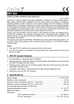
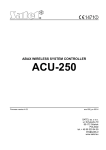
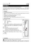
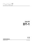
INT-KSG Keypad Installer Manual Firmware version 1.02 int-ksg_i_en 01/13 SATEL sp. z o.o. ul. Schuberta 79 80-172 Gdańsk POLAND tel. + 48 58 320 94 00 [email protected] www.satel.eu WARNINGS The keypad should be installed by qualified personnel. Read carefully this manual before proceeding to installation. Changes, modifications or repairs not authorized by the manufacturer shall void your rights under the warranty. The SATEL's goal is to continually upgrade the quality of its products, which may result in alterations of their technical specifications and firmware. The current information on the introduced modifications is available on our website. Please visit us: http://www.satel.eu The declaration of conformity may be consulted at www.satel.eu/ce The following symbols may be used in this manual: - note; - caution. The INT-KSG keypad is provided with touch keys and a large display which enables presenting functions in four lines after entering the menu. The dynamic menu adjusts automatically to the user's authority level and the system configuration. When in the screensaver mode, the display can show a wide array of information in a customized form. The new alarm system control feature (macro commands), specially created for the keypad, enables a variety of functions to be called quickly and easily just by touching a few keys. The keypad with firmware version 1.02 is dedicated to operating and programming the INTEGRA (firmware version 1.11 or newer) and INTEGRA Plus control panels. For programming of keypads with firmware version 1.02, the DLOADX program version 1.11 or newer is required. 1. Features Large display with backlight. LEDs indicating the state of partitions and system. Touch keypad with backlighting: 12 keys, designated according to the telephone standard, for entering data and quick access to some functions; key (identical to the key); 4 keys to navigate through menu; 3 keys to trigger alarms from the keypad; 4 keys to call macro commands: . Built-in sounder. 2 programmable hardwired zones: support for NO and NC type detectors, as well as roller shutter and vibration detectors; support for Single EOL, Double EOL and Triple EOL configuration (Triple EOL when working with INTEGRA Plus control panels); programming end-of-line resistor values. Tamper contact reacting to the housing opening or detaching from the wall. RS-232 (TTL) port for updating the keypad firmware. 2. Installation and hook-up Disconnect power before making any electrical connections. The INT-KSG keypad is designed for indoor installation. The place of installation should be readily accessible to the system users. The distance between the keypad and the control panel may be up to 300 m. Using the typical unshielded straight-through cable is recommended for making the electrical connections (it is not advisable to use the "twistedpair" type of cable – UTP, STP, FTP). If you use the twisted-pair type of cable, remember that the DTM and CKM (data and clock) signals must not be sent through one twisted-pair cable. 1. Open the keypad housing (see Fig. 1). 2. Pass the cables through the opening in the housing base. 3. Secure the housing base to the wall. 2 INT-KSG SATEL 4. Screw down the wires connecting the keypad to the control panel keypad bus to the DTM, CKM and COM terminals (see Fig. 3). The wires should be run in one cable. 5. Connect the wires to the terminals of additional zones, if any detectors are to be connected to them (the detectors are to be connected in the same way as to the control panel onboard zones). 6. Connect power supply to the keypad (terminals +12V and COM). The power supply can be provided from the control panel mainboard, an expander with power supply unit installed in the system, or from an additional power supply unit. 7. Place the front panel onto the catches, snap close the housing and insert the fastening screw. Fig. 1. Opening the housing. SATEL INT-KSG 3 Fig. 2. Keypad electronics board in the front panel. Explanations for Fig. 2: 1 - terminals: +12V - power supply input. COM - common ground. DTM - data. CKM - clock. RSA, RSB - unused terminals. Z1, Z2 - zones. 2 - tamper contact (NC). 3 - sounder. 4 - RS-232 (TTL) port – enables connecting the keypad to the computer COM port by means of the SATEL made cable, available with the DB9FC/RJ-KPL kit, and updating the keypad firmware afterwards. 4 INT-KSG SATEL Fig. 3. Connection of the keypad to the control panel. 3. Addressing Each keypad must have an individual address set in it: from the 0 to 3 range, if it is connected to the INTEGRA 24 or INTEGRA 32 control panel; from the 0 to 7 range, if it is connected to the INTEGRA 64, INTEGRA 128, INTEGRA 128-WRL, INTEGRA 64 Plus or INTEGRA 128 Plus control panel. By default, address 0 is set in all keypads. When started, only the control panel with factory default settings can provide support for all keypads connected to the bus, irrespective of the addresses set in them. In all other cases, the control panel will block operation of the keypads having identical addresses. The address set in the keypad determines the numbers to be given to the keypad zones (see the INSTALLER MANUAL for INTEGRA or INTEGRA Plus control panels). 3.1 Programming keypad address by means of service function 1. By means of any supported keypad, enter the control panel service mode ([SERVICE CODE] SERVICE MODE). 2. Start the function KEYPADS ADDR. (STRUCTURE HARDWARE IDENTIFICATION KEYPADS ADDR.). 3. The "This LCD address (n, 0-x)" message will appear on the displays of all keypads connected to the control panel (n – keypad address; 0-x – range of supported addresses). 4. Enter a new address in the selected keypad(s). The address change will be confirmed by four short and one long beeps. 5. To terminate the address change function, touch the key. The function will be terminated automatically after 2 minutes from being started. Termination of the function is equivalent to restarting the keypad (return to the main service mode menu will follow in the keypad from which the function has been started). SATEL INT-KSG 5 3.2 Programming keypad address without entering service mode This method is useful when – due to repeating addresses – the keypad support has been disabled and entering the service mode is impossible. 1. Disconnect keypad power supply (KPD) and signal wires CKM and DTM. 2. Short the keypad terminals CKM and DTM. 3. Switch on keypad power supply. 4. A message indicating the current address will appear on the display. 5. Enter a new address. The keypad will confirm execution of the function by four short and one long beeps. If it is necessary to change the entered address, touch the key (keypad restart will follow and a corresponding message will appear on the display). 6. Disconnect the keypad power supply. 7. Open the keypad terminals CKM and DTM. 8. Connect the keypad correctly to the control panel. 4. Keypad identification The system can only be programmed and operated from keypads that have been identified by the control panel. The keypad identification function should be run at the first startup of the control panel, and then each time when adding a new keypad or changing address in a keypad supported by the control panel. Disconnecting an identified keypad from the bus will trigger the tamper alarm. The identification function can be run by using the keypad (SERVICE MODE STRUCTURE HARDWARE IDENTIFICATION LCD KEYPADS ID.) or DLOADX program („Structure” window „Hardware” tab „Keypads” branch „Keypads identification” button). 5. Configuration of keypad settings Parameters and options of the INT-KSG keypad can be programmed by means of any LCD keypad (SERVICE MODE STRUCTURE HARDWARE LCD KEYPADS SETTINGS keypad name) or DLOADX program ("Structure" window "Hardware" tab "Keypads" branch keypad name). Creating the macro commands and configuring the screensaver is only possible in the DLOADX program. 5.1 Keypad parameters and options Shown in square brackets are the names used in LCD keypads. Name – individual name of the keypad (up to 16 characters). Partitions managed by keypad [Partitions] – the partitions which can be armed/disarmed or alarm in which may be cleared from the keypad. These functions are available to the users having a suitable authority level and access to those partitions. Using the service code you can operate all partitions, irrespective of which partitions are operated by the keypad. Show alarms of partitions [Alarms] – the partitions, the alarm from which will be indicated LED, sound, or a text message. on the keypad by Show fire alarms of partitions [Fire alarms] – the partitions, the fire alarm from which will be indicated on the keypad by LED, sound, or a text message. CHIME signal of zones [Chime zones] – the zones the violation of which will be indicated by beeps in the keypad. 6 INT-KSG SATEL Zone disabling CHIME [Chime bps. zone] – number of zone, which, if violated, will disable the CHIME feature for specified time. Bypass time [Chime bps. time] – time during which the CHIME signal will be disabled after violation of the zone which disables the signaling (time is counted from the zone restore). If the value 0 is programmed, the signaling will not be disabled. Fig. 4. Keypad parameters and options in DLOADX program. Quick Arm partitions [Quickarm part.] – the partitions which will be armed on touching successively the keys: 0 , 1 , 2 or 3 (see USER MANUAL). Show entry delay of partitions [Entry time p.] – the partitions, for which counting the entry delay will be indicated by text appearing on the LCD display. Show exit delay of partitions [Exit time part.] – the partitions for which counting the exit delay will be indicated by text appearing on the LCD display. Keypad zones – for each of the keypad zones can be defined whether it will be used or not. Auto-backlight – the backlight can go on optionally after a specific event in the system, e.g. starting the entry delay countdown in a selected partition, or violating a selected zone. SATEL INT-KSG 7 Date/Time format – selection of the format of time and date display on the keypad. LCD backlight – selection of the display backlight type. Keys backlight – selection of the keypad backlight type. Alarm messages – you can define whether the keypad is to display text messages about alarms: in partitions [Part.al.msg.]; from zones [Zone al.msg.]. Alarms – you can define which alarms will be triggered from the keypad: fire – touch and hold the panic – touch and hold the key for approx. 3 seconds. key for approx. 3 seconds. auxiliary [medical] – touch and hold the key for approx. 3 seconds. 3 wrong codes – enter an invalid code three times. Additional options – a set of additional options to start some functions of the keypad: key for Silent PANIC alarm [Silent panic] – with this option enabled, touching the approx. 3 seconds will trigger the silent panic alarm. Signaling entry delay [Entry time s.] – with this option enabled, the keypad will audibly signal the entry delay countdown. Signaling exit delay [Exit time sig.] – with this option enabled, the keypad will audibly signal the exit delay countdown. Signaling alarms [Alarm signal.] – with this option enabled, the keypad will signal the alarms audibly. Key sounds – with this option enabled, pressing the keypad keys is confirmed by beeps. Signaling troubles in partially arm [Trbl. in p.arm.] – with this option enabled, the keypad signals troubles by means of the LED, if some of the operated partitions are armed (the troubles are not signaled if all partitions are armed). Signal new trouble [New trbl. sign.] – with this option enabled, the keypad can audibly signal the occurrence of a new trouble (if the TROUBLE MEMORY UNTIL REVIEW system option is enabled). Show code entering [Show code ent.] – with this option enabled, entering the code is presented on the keypad display by asterisks. Show keypad name [Name (2nd row)] – with this option enabled, the keypad name is presented in the lower line of the display. Exit delay clearing enable [Fin. exit time] – with this option enabled, the exit delay time in partitions with the EXIT DELAY CLEARING option enabled can be shortened after pressing in turn the 9 keys. Show violated zones [Zone violation] – with this option enabled, violating the CHIME signal triggering zone result additionally in the zone name being displayed. Auto-Arm delay countdown signaling [Auto-arm delay] – with this option enabled, the auto-arm delay countdown in partition is signaled acoustically. Display mode switching [Dspl. mode chg.] – with the option enabled, you can toggle the display between the standby mode and the partition status display mode by using the 9 key. Show disarm messages [Show disarming] – if this option is enabled, the keypad will inform about disarming with a displayed message at all times. If the option is disabled – only in case of disarming from the given keypad. Show arm messages [Show arm] – if this option is enabled, the keypad will inform about disarming with a displayed message (irrespective of how the system was armed). 8 INT-KSG SATEL Quick control [Control (8#)] – if this option is enabled, the OUTS CONTROL user function can be started by pressing in turn the 8 keys (without the need to enter the user code). Sound volume – the function makes it possible to control loudness level of the keypad sounder. The function is unavailable in the DLOADX program. State inspections [Reviews] – you can select which of the functions started by holding the number keys will be available in the keypad. Fig. 5. "State inspections" tab, DLOADX program. Permanently displayed partitions [State part.] – you can select the partitions whose state will be permanently presented in the lower line of the display. Up to 16 partitions can be selected. The partitions are displayed successively: for example, if the partitions 3, 6 and 7 are selected, their state will be displayed in the first, second and third position of the display. Zone state [Zone characters] – you can define the symbols which will illustrate the state of zones. Partition state [Part. characters] – you can define the symbols which will illustrate the state of partitions. Code+arrows – you can define which functions will be started on entering the code and touching the selected arrow key. Tamper signaled in partition [Tamper in part.] – selection of the partition in which alarm will be signaled if the keypad tamper contact is opened or the keypad is disconnected from the control panel. SATEL INT-KSG 9 Fig. 6. "User functions definition" tab, DLOADX program. 5.2 Macro commands The macro commands related data are stored in the keypad memory. Before you proceed to defining the macro commands, read out the data from the keypad ("Read" button), and, after the programming is completed, write them to the keypad ("Write" button). These data are not read and written after you click the program main menu. button in the Macro command group – the list of macro commands that will be displayed in the keypad key. 4 groups of macro commands can be defined. on touching the Macro command group name – an individual name presented at the bottom of the display key (up to 8 characters). above the Macro command – a sequence of actions, composed of single commands, to be executed by the control panel on running the macro command. Macro command name – an individual name of macro command (up to 32 characters). Code – the code to be used for authorization when executing the macro commands. The code must have a suitable authority level for the macro commands to be possible to be executed. If, when running a macro command, it will turn out that the code is invalid (e.g. it has been changed in the meantime), the user will be able to enter the correct one. It will be automatically saved to the keypad memory (and replace the invalid code). Authorization required – if this option is enabled, the macro command will only be run after user authorization by means of a code. The code entered in the "Code" field will be ignored. Disabled if armed – if this option is enabled, the macro command will not be available, when any of the partitions operated by the keypad is armed. 10 INT-KSG SATEL Fig. 7. "Groups" tab, DLOADX program. Autoexecute – if this option is enabled and there is just one macro command in the group, key will not display the list of macro commands, but will run the macro touching the command at once (if the AUTHORIZATION REQUIRED option is enabled, authorization by means of a code will be necessary). Command – the function that can be assigned to a macro command, executed by the control panel. It can be: arming selected partitions in a defined mode; disarming selected partitions; clearing alarm in selected partitions; inhibiting selected zones; unbypassing selected zones; enabling selected outputs; disabling selected outputs; changing status of selected outputs; sending KNX telegram; sending key sequences. The partitions must be controlled by user code. The zones must not have the BYPASS DISABLED option enabled. SATEL INT-KSG 11 The outputs must be the 24. MONO SWITCH, 25. BI SWITCH, 105. SHUTTER UP, 106. SHUTTER DOWN or REMOTE SWITCH type (they need not be assigned to any group of outputs). The keypad can be used to control the KNX system, if the INT-KNX module is connected to the control panel. Fig. 8. "Definitions" tab, DLOADX program. Creating a group of macro commands 1. Click the "Groups" tab. 2. Click the group to be edited. 3. Enter the group name. 4. Click the "Add macro" button. Select the macro command to be added from the dropdown menu. 5. Click the "Write" button. The data will be written to the keypad. Creating a macro command 1. Click the "Definitions" tab. 2. Click the "New macro" button. A new macro command will appear in the list. 3. Enter a name for the new macro command. 4. If the macro command is to be run without entering the code by the user, enter the code with a suitable authority level. 12 INT-KSG SATEL 5. If running the macro command is to be each time preceded by user authorization, enable the AUTHORIZATION REQUIRED option. 6. If the macro command is not to be available, when any of the partitions operated by the keypad is armed, enable the DISABLED IF ARMED option. key, enable the 7. If the macro command is to be run instantly on touching the AUTOEXECUTE option (if so, only this single macro command is to be assigned to the group). 8. Select from the list one of the commands to be executed by the new macro command. 9. Select the partitions (arming / disarming, alarm clearing), zones (bypassing / unbypassing) or outputs (enabling / disabling outputs) controlled by the command. Click twice to select/deselect the required field. 10. Click the "Add" button. A new command will appear in the list of commands assigned to the macro command. After clicking the command you can still make a correction to the list of partitions / zones / outputs controlled by the command. After making the changes, click the "Change" button. 11. If necessary, repeat the steps 8-10 to add next commands. 12. Click the "Write" button. The data will be written to the keypad. 5.3 Screensaver The screensaver related data are stored in the keypad memory. Before you proceed to configuring the screensaver, read out the data from the keypad ("Read" button), and, after the programming is completed, write them to the keypad ("Write" button). These data are not read and written after you click the menu. button in the program main The screensaver mode turns on after the keypad is idle for 60 seconds, when no menu is displayed. When in the screensaver mode, the following information can be displayed: any text defined by the installer, state of selected partitions (select single partitions whose status will be displayed), state of selected zones in the form of symbols (select single zones whose status will be displayed), state of selected outputs in the form of symbols (select single outputs whose status will be displayed), temperature (indicate the control panel zone to which the temperature detector is assigned, and determine whether the temperature is to be displayed in degrees Celsius or Fahrenheit), date and time (particular elements, like the day, month, year, hour, minutes and seconds are to be configured individually), name of the keypad, state of selected zones in the form of messages (select individual zones whose state will be displayed, and define the content of messages for the normal state and for the violation, because these two states only are presented in the form of a message), state of the selected outputs in the form of messages (select individual outputs whose status will be displayed, and define the content of messages for the active and inactive output). SATEL INT-KSG 13 Fig. 9. "Screensaver" tab, DLOADX program. There are two font sizes available for use in the screensaver mode. Using the "drag and drop" method, you can easily select the place where the given information will be presented on the display. 5.4 End-of-line resistance The resistance data are stored in the keypad. Before you proceed to programming the resistor values, read out the data from the keypad ("Read" button), and, after the programming is completed, write them to the keypad ("Write" button). These data are not read and written after you click the button in the program main menu. For the keypads with firmware version 1.02 (or newer), which are working with the INTEGRA Plus control panels, the values of end-of-line resistors are not programmed individually for each keypad (the "EOL resistance value" tab is not available). You must use the same resistors as those for the control panel onboard zones (the value of EOL resistors for control panel onboard zones is programmable). The value of EOL resistors is programmable. You can program the value of R1 and R2 resistors for Double EOL configuration (numbering of the resistors is shown in Fig. 10). The resistor value can range from 500 to 15 k, however the sum of programmed values must not exceed 15 k. For the R2 resistor, you can program value 0. In such a case, the value of resistors used in the Double EOL configuration must be equal to half the value programmed for the R1 resistor, but not less than 500 . By default, the following values are programmed: R1 = 1,1 k; R2 = 1,1 k. The resistor value for Single EOL configuration is the sum of values programmed as R1 and R2. 14 INT-KSG SATEL Fig. 10. Numbering of EOL resistors (same for the NO detector). T – tamper. A – alarm. 6. Specifications Supply voltage ................................................................................................... 12 V DC ±15% Standby current consumption ........................................................................................165 mA Maximum current consumption. .....................................................................................175 mA Environmental class according to EN50130-5 .........................................................................II Working temperature range ................................................................................ -10°C…+55°C Maximum humidity ..........................................................................................................93±3% Housing dimensions (width x height x thickness)........................................ 143 x 156 x 22 mm Weight............................................................................................................................... 320 g