1
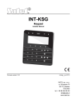
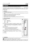
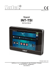
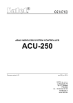
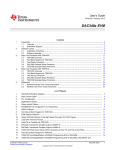
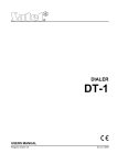
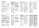
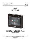
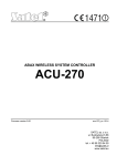
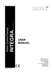
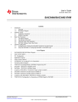
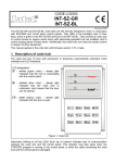
INT-AV AUDIO ALARM VERIFICATION MODULE int-av_en 08/13 The INT-AV module enables audio alarm verification to reduce the number of false alarms. After having received alarm message from the control panel, the operator of telephone monitoring station is able to listen-in on the sounds coming from the premises to confirm whether there is an intrusion. Owing to the module, the operator can try to contact the people on the premises to determine if the alarm is real or false. The listen-in and talk features are also available to the alarm system users. They can call the control panel number and, after entering the telephone code, get access to these features at any time. Listen-in and communication with the people on the protected premises are possible due to the INT-AVT terminals. The terminal is equipped with a microphone and a speaker. The module delivery set includes one INT-AVT terminal. Up to four INT-AVT terminals can be connected to the module. The module works with the INTEGRA / INTEGRA Plus control panels (firmware version 1.12 or newer). This manual applies to the module electronics version 1.4 and firmware version 1.00 (or newer). Notes: Only one INT-AV module can be connected to the control panel. If an INT-VG module is connected to the control panel, the module firmware version must be 1.02 or newer. 1. INT-AV module features Two-way (listen-in / talk) audio alarm verification. Keeping telephone connection with the monitoring station open after the control panel has sent alarm message (line hold mode). Receiving phone calls from the monitoring station after the control panel has sent alarm information (call back mode). Availability of the listen-in / talk features to the users having a telephone code. Support for up to four INT-AVT terminals. 2. Specifications Supply voltage ................................................................................................... 12 V DC ±15% Standby current consumption ..........................................................................................35 mA Maximum current consumption (INT-AV + 1xINT-AVT) .................................................160 mA Maximum current consumption (INT-AV + 4xINT-AVT) .................................................500 mA Environmental class according to EN50130-5 ......................................................................... II Operating temperature range..................................................................................-10...+55 °C Maximum humidity .......................................................................................................... 93±3% Dimensions INT-AV (electronics board) ............................................................ 57 x 80 mm INT-AVT (enclosure).............................................................35 x 127 x 22 mm 2 INT-AV SATEL Weight INT-AV....................................................................................................... 46 g INT-AVT..................................................................................................... 42 g The declaration of conformity may be consulted at www.satel.eu/ce 3. Electronics board Fig. 1. Module electronics board. DIP-switch package (see DIP-SWITCHES). wires to the PIN5 type plug used for connecting the module to a dedicated socket on the control panel electronics board (socket to connect a voice synthesizer). LED indicating communication with the control panel: blinking – exchanging data with the control panel; ON – no communication with the control panel. sockets for connecting the INT-VG voice module, CA-64 SM voice synthesizer expander or SM-2 synthesizer. RS-232 port (TTL standard) for updating the module firmware (connection with the computer can be made with the use of cables available in the DB9FC/RJ-KPL set, manufactured by SATEL). 3.1 Terminals - communication bus (to be connected to the terminals of control panel communication bus). +SP1- ... +SP4- - terminals for connecting the INT-AVT terminal speaker (the digit corresponds to the speaker number). +M1- ... +M4- terminals for connecting the INT-AVT terminal microphone (the digit corresponds to the microphone number). DTA, CLK SATEL INT-AV 3 3.2 DIP-switches The DIP-switches from 1 to 5 are used to set the address. A numerical value is assigned to each switch (in ON position – see Table 1; in OFF position – 0). The sum of these numerical values corresponds to the address set. The DIP-switches allow for setting addresses in the 0 to 31 range. 1 2 3 4 5 DIP-switch number Numerical value 1 2 4 8 16 Table 1. Numerical values assigned to DIP-switches in ON position. Position of the switch 6 is irrelevant. The switches 7 and 8 are used to determine the control panel to which the module is connected: module connected to the INTEGRA 128-WRL control panel – both switches must be set in ON position; module connected to another INTEGRA / INTEGRA Plus control panel – both switches must be set in OFF position. 4. Installation Disconnect power before making any electrical connections. The INT-AV module and INT-AVT terminals should be installed indoors, in spaces with normal air humidity. 4.1 Installing the INT-AV module 1. Secure the module in the control panel enclosure. 2. Connect the CLK and DTA terminals to the corresponding terminals of the control panel communication bus. It is recommended that unscreened straight-through cable be used to make the connection. 3. Connect the PIN5 plug to the socket on the control panel electronics board (socket to connect a voice synthesizer). 4. Screw the wires connecting the module with the INT-AVT unit, as required. The way of connecting the screw terminals of INT-AVT unit and module is illustrated in Fig. 2. Using a straight-through unscreened cable is recommended. The permissible distance between the communication terminal and the module is 100 m. Note: Resistance of the wires connecting the INT-AVT unit with the INT-AV module has an effect on the audio playback volume (the higher the resistance, the lower the volume) and the current consumption. 5. Use the DIP-switches to set the module address and determine the control panel to which the module is connected. 4 INT-AV SATEL Fig. 2. The way of connecting INT-AVT units to INT-AV module. Proceed in the same way to connect next units (i.e. unit 3 to screw terminals designated with digit 3, and unit 4 to screw terminals designated with digit 4). 4.2 Installing the INT-AVT terminal When selecting the installation place, bear in mind that curtains, drapes, upholstery, acoustic tiles, etc. absorb sound and, as a result, make it difficult, if not impossible, to use the listen-in feature. It is not advisable to install the terminal in the vicinity of equipment which generates noise during operation (e.g. fans, air conditioners, refrigerators). 1. Remove the screw, lift the enclosure cover and detach it (see Fig.. 3). The cover will still be connected to the base by the speaker wires. When opening the INT-AVT terminal enclosure be careful not to rip off the speaker attached to the base. Any changes in the construction of the INT-AVT terminal may result in malfunctioning of the device. 2. 3. 4. 5. 6. 7. Disconnect the speaker plug from the electronics board. Put the enclosure base to the wall and mark the location of mounting holes. Drill the holes for wall plugs (screw anchors). Run wires through the hole in the enclosure base. Using wall plugs (screw anchors) and screws, fasten the enclosure base to the wall. Screw the wires connecting the INT-AVT unit with the INT-AV module to the corresponding screw terminals. The way of connecting the screw terminals of INT-AVT unit and module is shown in Fig. 2. 8. Connect the speaker plug to the electronics board. 9. Replace the cover and then lock it with the screw. SATEL INT-AV 5 Fig. 3. Opening the INT-AVT terminal enclosure. 5. Start-up and identification of the module After completion of the installation work, you can power-up the alarm system. After start-up, the LED on the module electronics board will ON. As the control panel supports only identified modules, you must run the identification function. To do so you can use either: LCD keypad: SERVICE MODE STRUCTURE HARDWARE IDENTIFICATION EXPANDERS ID.; DLOADX program: "Structure" window "Hardware" tab "Expansion modules" item "Exp. modules identification" button. The control panel controls presence of the identified modules, and in the case of the INT-AV module, also for presence of the INT-AVT terminals connected to the module. Disconnecting the module from communication bus, changing the position of DIP-switches, swapping the module with another one, in which the DIP-switches are set in the same way, or disconnecting the INT-AVT terminal, will trigger the tamper alarm. Note: The identification function must be run every time after a new INT-AVT terminal is connected to the identified module. 6. Programming Programming is performed through the control panel, by means of a keypad or a computer running the DLOADX program. Configuration of the module settings is possible using: LCD keypad: SERVICE MODE STRUCTURE HARDWARE EXPANDERS SETTINGS [select module from the list of devices]; DLOADX program: "Structure" window "Hardware" tab "Expansion modules" item [click on the module on the list of devices] (see Fig. 4). 6 INT-AV SATEL Fig. 4. DLOADX program window with INT-AV module settings. 6.1 Parameters and options Shown in square brackets are the names of parameters and options presented on the keypad display. Name – individual device name (up 16 characters). Station access phone code [INT-AV code] – the code the monitoring station operator must enter to be able to initiate the listen-in / talk session. Verif. after reporting [Verify] – you can specify for each telephone number of the monitoring station whether, in the event of an alarm, message on the possibility to initiate the listen-in / talk session is to be sent. Simplified activation [Code=1tone] – you can specify for each telephone number of the monitoring station whether alarm verification in the line hold mode is to be possible on pressing any key on the phone (receiving any DTMF tone by the control panel). If this option is disabled, alarm verification by the monitoring operator station will only be possible after entering the code. The option is available, if the VERIF. AFTER REPORTING option is enabled for the given telephone number. Waiting time to call back after the event [Wait aft.event] – the time counted from the moment the monitoring station is informed about the possibility to initiate the listen-in / talk session. Then the control panel is waiting for the monitoring station operator to call back. Waiting time to call back after 88 command [Wait aft.disc.] – the time counted from the moment the listen-in / talk session is terminated by the monitoring station operator using the DTMF command, which provides for the possibility of call back. Then the control panel is waiting for the monitoring station operator to call back one more time. Connection holding time [Runtime] – the time counted after each DTMF tone received by the control panel, during which the phone connection is kept open. SATEL INT-AV 7 Microphone 1...4 – if this option is enabled, the selected microphone is turned on by default during the listen-in / talk session (sending sounds from the moment the session is started). You can toggle the microphone on / off during the session, using the DTMF command. Speaker 1...4 – if this option is enabled, the selected speaker is turned on by default during the listen-in / talk session (it can emit sounds from the moment the session is started). You can toggle the speaker on / off during the session, using the DTMF command. Listen-in only [Only listen] – if this option is enabled, only the listen-in feature is available. INT-AVT button enabled [AVT buttons] – if this option is enabled, the button in INT-AVT terminals is supported. Pressing the button on any terminal when the listen-in / talk session lasts will turn on the microphone and the speaker on that terminal and turn them off on all the other terminals. Connection signaling [Sound signal.] – if this option is enabled, an interrupted tone will be generated in the handset after establishing connection with the module. This signaling will continue until any DTMF tone is received by the module. Listen-in only in silent alarm [Silent alarm] – if this option is enabled, only the listen-in feature will be available in the event of silent alarm. SATEL standard commands – if this option is enabled, the module can be operated by means of DTMF commands compliant with SATEL standard, and if it is disabled, by means of DTMF commands compliant with SIA standard. All command are described in section DTMF COMMANDS. No auto-reset after three module tamper alarms – it is possible to disable the feature limiting the number of tamper alarms from the expander to three (this feature prevents the same events from being repeatedly recorded and applies to consecutive, non-cleared alarms). Tamper signaled in part. – the partition where alarm will be triggered in case of the module tamper. 7. Using the listen-in / talk features Notes: When using the listen-in / talk features, the alarm signaling by sirens and keypads is disabled. The listen-in / talk features are available from touch-tone phones. 7.1 Monitoring station operator The operator of monitoring station will be able to initiate the listen-in / talk session after the monitoring station has been informed about the possibility to use this features. The control panel sends such information when the following conditions are met: an alarm has occurred; an INT-AV module is connected to the control panel; alarm verification option has been provided for the given phone number of the monitoring station. For the Ademco Express and pulse formats, it is necessary to program the event code which will inform the monitoring station about the possibility to initiate the listen-in / talk session. Alarm verification can be performed in two modes: line hold mode; call back mode. 8 INT-AV SATEL Line hold mode Having sent information on the possibility of using the listen-in / talk features, the control panel will hold the phone line open for 15 seconds. If, during this time, the control panel receives any DTMF tone, the call holding time will be prolonged. It will allow the operator to enter the code to initiate the listen-in / talk session (the module can be configured so as to start a listen-in / talk session by pressing any key on the phone, i.e. by a single DTMF tone). The module is controlled by means of the DTMF commands (see section DTMF COMMANDS). Call back mode Alarm verification in the call back mode is possible when the ANSWERING - AUDIO option is enabled in the control panel. The operator can call the control panel to initiate the listen-in / talk session for a specific period of time after: information on the possibility of initiating the listen-in / talk session is received by the monitoring station (see description of the WAITING TIME TO CALL BACK AFTER THE EVENT parameter p. 6); terminating the listen-in / talk session with the DTMF command which provides for call back possibility (see description of the WAITING TIME TO CALL BACK AFTER 88 COMMAND parameter p. 6). Connection with the control panel can be established using one of the following methods (the installer specifies which method is supported by the control panel): single call – call the telephone number of control panel. The control panel will answer the call after the number of rings programmed by the installer. double call – call the telephone number of control panel. Hang up after the number of rings programmed by the installer. Call again within three minutes. The call will be answered by the control panel immediately. Establishing the connection will be signaled by three short beeps. After the connection is established, the operator must enter the code from the phone keypad to initiate the listen-in / talk session. The module is operated by means of the DTMF commands (see section DTMF COMMANDS). Note: The code for authorization of the monitoring station will be treated as an invalid one, unless countdown of the waiting time to callback is running in the control panel. 7.2 System user The user can initiate the listen-in / talk session at any moment, if he/she has a phone code, and the ANSWERING - AUDIO option is enabled in the control panel. The procedure of establishing connection with the control panel is identical as in the case of the monitoring station operator calling back the control panel. After the connection is established, the user must enter the phone code from the phone keypad. 4 short beeps and 1 long beep will confirm granting access to the call answering function. If the INT-VG voice module is connected to the control panel, the voice menu messages will be played back to inform the user, e.g. how to get access to the listen-in / talk features. If the INT-VG voice module is not connected to the control panel, the user must press the 3 and # keys within 15 seconds of entering the code to initiate the listen-in / talk session (see also the control panel user manual and the description of how to use the call answering and telephone control features). The module is operated by means of the DTMF commands (see section DTMF COMMANDS). SATEL INT-AV 7.3 DTMF commands After starting the listen-in / talk session, the level 0 commands are available. Level 0 Standard SIA SATEL 0 5# 1 1# 2 2# 3 4 6 3# 4# 6# 77 7# 88 99 # *1 *2 8# 0# * #1 #2 Command description Returns to the initial session settings Activates high gain talk to the premises from all speakers Activates two-way communication with the premises at all speakers and at all microphones Activates high gain listen-in from the premises from all microphones Activates low gain talk to the premises from all speakers Activates low gain listen-in from the premises from all microphones Terminates session and returns to phone answering function (if the INT-VG module is connected to the control panel, returns to the voice menu) Terminates session with call back (for station operator) Terminates session Cancels first digit of a 2 digit command Activates the level 1 command set Activates the level 2 command set Level 1 Standard SIA SATEL 0 5# 1 1# 2 2# 3 3# 4 4# 5 6# 6 7# 7 8# 8 9# 99 0# # * 0 #0 * #2 *2 Command description Returns to the initial session settings Turns microphone 1 on Turns microphone 2 on Turns microphone 3 on Turns microphone 4 on Turns microphone 1 off Turns microphone 2 off Turns microphone 3 off Turns microphone 4 off Terminates session Cancels first digit of a 2 digit command Activates the level 0 command set Activates the level 2 command set 9 10 INT-AV SATEL Level 2 Standard SIA SATEL 0 5# 1 1# 2 2# 3 3# 4 4# 5 6# 6 7# 7 8# 8 9# 99 0# # * 0 #0 * #1 *1 Command description Returns to the initial session settings Turns speaker 1 on Turns speaker 2 on Turns speaker 3 on Turns speaker 4 on Turns speaker 1 off Turns speaker 2 off Turns speaker 3 off Turns speaker 4 off Terminates session Cancels first digit of a 2 digit command Activates the level 0 command set Activates the level 1 command set 8. Updating module firmware When a new version of the module firmware comes out, it will be available on the www.satel.eu site. Run the program downloaded from the manufacturer's site. Instructions will be displayed regarding the firmware update procedure. Note: When updating the module firmware, make sure that the DIP-switches 3 and 4 on the electronics board are set in OFF position. SATEL sp. z o.o. • ul. Schuberta 79 • 80-172 Gdańsk • POLAND tel. 58 320 94 00 • [email protected] www.satel.eu