1
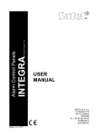
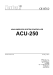
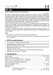
int-tsi_i_en 12/13 Keypad INT-TSI Installer Manual Firmware version 1.00 SATEL sp. z o.o. • ul. Schuberta 79 • 80-172 Gdańsk • POLAND tel. 58 320 94 00 • [email protected] www.satel.eu WARNINGS The keypad should be installed by qualified personnel. Read carefully this manual before proceeding to installation. Changes, modifications or repairs not authorized by the manufacturer shall void your rights under the warranty. Warning This is a Class A product. In a domestic environment this product may cause radio frequency interference in which case the user may be required to take adequate measures. Section “Installation and hook-up” contains information on how to minimize the radio interference. The SATEL's goal is to continually upgrade the quality of its products, which may result in alterations of their technical specifications and firmware. The current information on the introduced modifications is available on our website. Please visit us: http://www.satel.eu The declaration of conformity may be consulted at www.satel.eu/ce The following symbols may be used in this manual: - note; - caution. The INT-TSI keypad makes possible the operation and programming of INTEGRA and INTEGRA Plus control panels with firmware version 1.12 of 2013-11-27 or newer. For programming of the keypad settings, the DLOADX program version 1.12 or newer is required. To set up the user interface, the TSI BUILDER program should be used. 1. Features 7" touch screen with 800 x 480 resolution. Fully customizable graphical user interface. Widgets to allow the user to operate the keypad and control the alarm system and automation devices connected to the control panel. Quick launching of different functions by means of macro commands. Displaying images from web cameras (JPEG and MJPEG). Ability to display a slide show as screen saver. ARM Cortex A8 single-core processor. Built-in reader of microSD memory cards. Built-in two 2 W speakers. 2 programmable hardwired zones: – support for NO and NC type detectors, as well as roller shutter and vibration detectors; – support for Single EOL, Double EOL and Triple EOL configuration (Triple EOL when working with INTEGRA Plus control panels); – programming end-of-line resistor values. Tamper contact reacting to the enclosure opening or detaching from the wall. 2. Specifications Supply voltage ................................................................................................... 12 V DC ±15% Standby current consumption ........................................................................................500 mA Maximum current consumption......................................................................................620 mA Supported memory cards........................................................................microSD, micro SDHC Environmental class according to EN50130-5 ......................................................................... II Working temperature range ................................................................................ -10°C…+55°C Maximum humidity .......................................................................................................... 93±3% Enclosure dimensions (width x height x thickness)......................................196 x 129 x 22 mm Weight............................................................................................................................... 430 g 2 INT-TSI SATEL 3. Keypad description Fig. 1. Inside of enclosure. terminals: COM +12V CKM DTM Z1, Z2 RSA, RSB - common ground. power supply input. clock. data. zones. unused terminals – intended for future applications (RS-485). tamper switch. RS-232 connectors (for service purposes). reader of microSD memory cards. USB MINI-B socket (for future applications). RJ-45 socket to connect the Ethernet network. Provided with two LEDs. The green one indicates connection to the network and data transfer, and the yellow one – the negotiated transmission rate (ON: 100 Mb; OFF: 10 Mb). 3.1 microSD memory card On the microSD memory card: the installation file of TSI BUILDER program is provided; SATEL INT-TSI 3 the keypad configuration data are stored; new keypad firmware version is placed; the events downloaded from the control panel are saved; the photos which will be used for the slide show can be placed. The keypad supports the microSD and microSDHC memory cards. To insert or remove the memory card you must open the keypad enclosure, therefore, if the alarm system works, remember to enter the service mode. If the microSD card is removed from the working keypad, you will only be able to operate the alarm system by using the terminal. After you insert the microSD card into the working keypad, a window will be displayed in which you should tap to restart the keypad. 3.1.1 Inserting the microSD card 1. Open the keypad enclosure (see: Fig. 2). 2. Insert the card into its slot and push until it clicks into place. The card contacts should be directed toward the display. 3. Close the keypad enclosure. 3.1.2 Removing the microSD card 1. Open the keypad enclosure (see: Fig. 2). 2. Push the card to release it. 3. Remove the card from its slot. 4. Installation and hook-up Disconnect power before making any electrical connections. The device is designed to be used only in the local area networks (LAN). It must not be connected directly to the public computer network (MAN, WAN). Connection to the public network may only be done through a router or xDSL modem. The INT-TSI keypad is designed for indoor installation. The place of installation should be readily accessible to the system users. 1. Open the keypad enclosure (see Fig. 2). The enclosure opening tool, shown in the illustration, is included in the keypad delivery set. 2. Place the enclosure base on the wall and mark the location of mounting holes. 3. Drill the holes for wall plugs (screw anchors). 4 INT-TSI SATEL Fig. 2. Opening the enclosure. 4. Install in the wall a junction box to which cables will be connected and in which a ferrite ring will be placed. The purpose of the ferrite ring delivered with the keypad is to decrease the electromagnetic interference. Make sure that the ferrite ring is positioned as close as possible to the enclosure. 5. Wrap the cables around the ferrite ring (see: Fig. 3), but no more than 3 turns per cable. Fig. 3. The cable wrapped around the ferrite ring 6. Pass the cables through the opening in the enclosure base. 7. Using wall plugs (screw anchors) and screws, fasten the enclosure base to the wall. 8. Connect the DTM, CKM and COM keypad terminals to the appropriate terminals of the control panel keypad bus (see Fig. 4). It is recommended that the unscreened straightthrough cable be used for making the connection. If you use the twisted-pair type of cable, remember that CKM (clock) and DTM (data) signals must not be sent through one twisted-pair cable. The wires must be run in one cable. The length of cables must not exceed 300 m. SATEL INT-TSI 5 Fig. 4. Connection of the keypad to the control panel. 9. Connect the wires to the terminals of additional zones, if any detectors are to be connected to them (the detectors are to be connected in the same way as to the control panel onboard zones). 10. Connect the power supply wires to the keypad (terminals +12V and COM). The keypad can be powered from the control panel mainboard, an expander with power supply or from an additional power supply unit. The table below shows requirements regarding the power wires (+12V and COM), if conductors with 0.5 mm diameter are used. Distance from control panel up to 25 m 25 – 50 m 50 – 75 m 75 – 100 m Number of parallel connected wires 1 2 3 4 In the case of INTEGRA 24, INTEGRA 32 and INTEGRA 128-WRL control panels, the +KPD output cannot be used to power the INT-TSI keypad. You should use the OUT1 or OUT2 high-current output, programmed as type 41. POWER SUPPLY. A function is available in the keypad which makes it possible to check if the keypad power supply is appropriate (see the INT-TSI keypad user manual). 11. If the keypad is to be connected to the Ethernet network (image from the web cameras is to be displayed), connect the cable terminated with RJ-45 plug to the dedicated socket. Use the cable compliant with the 100Base-TX standard (the same as used for connecting computer to the network). It is advisable to use the flat network cable, which is more flexible, and secure the cable using a cable tie (see Fig. 5). 12. Place the front panel onto the catches, snap close the enclosure. After the first start-up of the keypad, downloading of the alarm system data from the control panel will begin. It may last up to 20 minutes and make using the keypad somewhat difficult during that time. 6 INT-TSI SATEL Fig. 5. Securing the Ethernet cable. 5. Addressing The keypad must have an individual address set in it: from the 0 to 3 range, if it is connected to the INTEGRA 24 or INTEGRA 32 control panel; from the 0 to 7 range, if it is connected to the INTEGRA 64, INTEGRA 128, INTEGRA 128-WRL, INTEGRA 64 Plus, INTEGRA 128 Plus or INTEGRA 256 Plus control panel. By default, address 0 is set in the keypad. When started, only the control panel with factory default settings can provide support for all keypads connected to the bus, irrespective of the addresses set in them. In all other cases, the control panel will block operation of the keypads having identical addresses. The address set in the keypad determines the numbers to be given to the keypad zones (see the INSTALLER MANUAL for INTEGRA or INTEGRA Plus control panels). 5.1 Programming keypad address by means of service function 1. Find the tab in which the terminal is available (in the keypad with factory settings, tap the icon on the tab bar). 2. Enter the service code (by default: 12345) and touch the be displayed. key. The user menu will key. The service mode will start up. 3. Touch the 4. Start the KEYPADS ADDR. function (STRUCTURE HARDWARE IDENTIFICATION KEYPADS ADDR.). A window will be displayed in which you can set the address (after starting the function, you can set the address in all keypads connected to the control panel). 5. Using the and keys, set the address and then tap the with service menu will be displayed on the screen. icon. The terminal SATEL INT-TSI 7 5.2 Programming address without entering the service mode This method is useful when – due to repeating addresses – the keypad support has been disabled and entering the service mode is impossible. 1. Turn off keypad power supply. 2. Disconnect wires from the keypad terminals CKM and DTM. 3. Short the keypad terminals CKM and DTM. 4. Turn on keypad power supply. A window will be displayed where you can set the address. 5. 6. 7. 8. 9. Using the and keys, set the address and then tap the Turn off keypad power supply. Open the keypad terminals CKM and DTM. Connect wires, as required, to the keypad terminals CKM and DTM. Turn on keypad power supply. icon. 6. Keypad identification The alarm system can only be programmed and operated from keypads that have been identified by the control panel. The keypad identification function should be executed at the first start-up of the control panel, and then each time when adding a new keypad or changing address in a keypad supported by the control panel. Disconnecting an identified keypad from the bus will trigger the tamper alarm. The identification function can be run by using: the keypad (SERVICE MODE STRUCTURE HARDWARE IDENTIFICATION LCD KEYPADS ID.); DLOADX program (”Structure” window ”Hardware” tab ”Keypads” item ”Keypads identification” button). The procedure of entering the service mode by means of the INT-TSI keypad is described in section „Programming keypad address by means of service function” (p. 6). 7. Synchronizing event memory After the keypad start-up, a window will be displayed to inform you that synchronization of the event memory is in progress. During that time, the keypad is downloading events from the control panel. The events read from the control panel memory are saved to the microSD memory card in the keypad. After synchronization of the event memory, the keypad will be automatically downloading new events from the control panel. The keypad event memory is unlimited, which means that a greater number of events may be saved to the memory card than to the memory of the control panel. The DLOADX program makes it possible to export the system data file, containing e.g. the event log (see "Exporting system data by means of the DloadX program" p. 13). You can read in this file when creating a user interface project in the TSI BUILDER program (see p. 16). As a result, when synchronizing the event memory, the keypad will only have to download the events which took place after the file was exported. This solution significantly reduces the synchronization procedure in the case of those control panels in the memory of which a large number of events is saved. If the whole event memory of the control panel is to be available in the keypad, the synchronization procedure must not be interrupted. 8 INT-TSI SATEL If the file containing the event memory becomes corrupted or deleted from the memory card, then the procedure of synchronizing event memory will be started. 8. Keypad configuration 8.1 Parameters and options Parameters and options of the INT-TSG keypad can be programmed by means of: LCD keypad (terminal SERVICE MODE STRUCTURE HARDWARE LCD KEYPADS SETTINGS [keypad name]); DLOADX program ("Structure" window "Hardware" tab "Keypads" item [keypad name]). The procedure of entering the service mode by means of the INT-TSI keypad is described in section „Programming keypad address by means of service function” (p. 6). Shown in square brackets are the names used in keypads. 8.1.1 Keypad Name – individual name of the keypad (up to 16 characters). Partitions managed by keypad [Partitions] – the partitions which can be armed/disarmed or alarm in which may be cleared from the keypad. These functions are available to the users having a suitable authority level and access to those partitions. Using the service code you can operate all partitions, irrespective of which partitions are operated by the keypad. Show alarms of partitions [Alarms] – the keypad can signal burglary alarms from selected partitions. Show fire alarms of partitions [Fire alarms] – the keypad can signal fire alarms from selected partitions. CHIME signal of zones [Chime zones] – the keypad can audibly signal violation of selected zones. If the zone is armed, violation will not trigger the CHIME signal. Zone disabling CHIME [Chime bps. zone] – zone, which, if violated, will disable the CHIME feature for specified time. Bypass time [Chime bps. time] – time during which the CHIME signal will be disabled after violation of the zone which disables the signaling (time is counted from the zone restore). If the value 0 is programmed, the signaling will not be disabled. Quick Arm partitions [Quickarm part.] – partitions which will be armed in case of the quick arming, i.e. without user authorization. Show entry delay of partitions [Entry time p.] – the partitions, for which counting the entry delay will be indicated by text appearing on the display. Show exit delay of partitions [Exit time part.] – the partitions for which counting the exit delay will be indicated by text appearing on the display. Alarm messages – you can define whether the keypad is to display text messages about alarms: in partitions [Part.al.msg.]; – from zones [Zone al.msg.]. SATEL INT-TSI 9 Fig. 6. "Keypad" tab in DLOADX program. Alarms – you can define which alarms will be triggered from the keypad: – fire – using the widget or terminal (by long pressing the key for about 3 seconds). – panic – using the widget or terminal (by long pressing the seconds). key for about 3 10 INT-TSI SATEL – auxiliary [medical] – using the widget or terminal (by long pressing the key for about 3 seconds). – 3 wrong codes – entering invalid codes three times. Silent PANIC alarm [Silent panic] – with this option enabled, the panic alarm triggered from the keypad will be a silent alarm (without audible alarm signal). Sign. entry delay [Entry time s.] – with this option enabled, the keypad will audibly signal the entry delay countdown. Sign. exit delay [Exit time sig.] – with this option enabled, the keypad will audibly signal the exit delay countdown. Sign. alarms [Alarm signal.] – with this option enabled, the keypad will signal the alarms audibly. Key sounds – when this option is enabled, touching the keypad screen is confirmed by a beep. Sign. trbl. in part. arm [Trbl. in p.arm.] – with this option enabled, the keypad signals troubles, if some of the operated partitions are armed (the troubles are not signaled if all partitions are armed). Sign. new trouble [New trbl. sign.] – with this option enabled, the keypad can audibly signal the occurrence of a new trouble (if the TROUBLE MEMORY UNTIL REVIEW system option is enabled). New trouble signaling is cleared after the troubles have been reviewed by the user. Exit delay clearing enable [Fin. exit time.] – with this option enabled, the exit delay time in partitions with the EXIT DELAY CLEARING option enabled can be shortened by means of: – the widget (macro command reducing the exit delay time); – the terminal (after tapping in turn the and keys). Show viol. zones [Zone violation] – with this option enabled, violating the CHIME signal triggering zone result additionally in the zone name being displayed. Auto-Arm delay countdown [Auto-arm delay] – with this option enabled, the auto-arm delay countdown in partition is signaled acoustically. Show disarm messages [Show disarming] – if this option is enabled, the keypad will inform about disarming with a displayed message at all times. If the option is disabled – only in case of disarming from the given keypad. Show arm messages [Show arm] – if this option is enabled, the keypad will inform about arming with a displayed message. Quick control [Control (8#)] – if this option is enabled the user can: – use the zone control widgets in the template available without login; – start the CONTROL user function from the terminal after tapping in turn the and keys (without entering the code). Keypad zones – for each of the keypad zones can be defined whether it will be used or not. Tamper signaled in part. [Tamper in part.] – selection of the partition in which alarm will be signaled if the keypad tamper contact is opened or the keypad is disconnected from the control panel. Power supply source [Power supply] – you can define the source from which the keypad is powered: control panel mainboard, expander with power supply or other power source. If you select the control panel mainboard or expander with power supply, the keypad SATEL INT-TSI 11 backlight intensity will be reduced to approx. 15% in case of loss of AC power supply of the control panel or expander. 8.1.2 State inspections 1 – zone state [Zones] – if this option is enabled: – the user can check the state of zones on the terminal by long pressing the key with number 1 for about 3 seconds; – the widget presenting the state of zones will always indicate the status of all zones (you can use the widget in the template available without login). 4 – partitions armed [Partitions] – if this option is enabled: – the user can check the state of partitions on the terminal by long pressing the key with number 4 for about 3 seconds; – the widget presenting the state of partitions will always indicate the status of all partitions (you can use the widget in the template available without login). Fig. 7. "State inspections” tab in DLOADX program. 5 – alarm events memory [Alarms log] – if this option is enabled, the user can review the alarm memory on the terminal by long pressing the key with number 5 for about 3 seconds. 6 – trouble memory [Troubles log] – if this option is enabled, the user can review the trouble memory on the terminal by long pressing the key with number 6 for about 3 seconds. 7 – trouble status [Troubles] – if this option is enabled: – the user can review the current troubles on the terminal by long pressing the key with number 7 for about 3 seconds; – the widget presenting the troubles can be used in the template available without login. 12 INT-TSI SATEL 8 – chime on/off [Chime changing] – if this option is enabled, the user can switch on/off the CHIME signal in the keypad by means of the terminal, long pressing the key with number 8 for about 3 seconds. Zone state [Zone characters] – you can define the symbols which will be used by the terminal to illustrate the state of zones. Partition state [Part. characters] – you can define the symbols which will be used by the terminal to illustrate the state of partitions. 8.1.3 EOL resistance value The resistance data are stored in the keypad. Before you proceed to programming the resistor values, read out the data from the keypad ("Read" button), and, after the programming is completed, write them to the keypad ("Write" button). These data are not read and written after you click the button in the program main menu. The value of EOL resistors is programmable. Depending on the control panel to which the keypad is connected: INTEGRA: parameters of the EOL resistors should be defined for zones in a single keypad. Value of the resistors R1 and R2 is to be programmed (numbering of the resistors is shown in Fig. 9). You can enter values from 500 to 15 k. The total resistance (R1+R2) may not exceed 15 k. For the R2 resistor, you can program value 0. In such a case, the value of resistors used in the Double EOL configuration must be equal to half the value programmed for the R1 resistor (the value of one resistor must not be less than 500 ). By default, the following values are programmed: R1 = 1,1 k; R2 = 1,1 k. The resistor value for Single EOL configuration is the sum of R1 and R2 resistors. Fig. 8. "EOL resistance value" tab in DLOADX program. INTEGRA Plus: parameters of the EOL resistors should be defined for the mainboard zones. The same parameters will be set automatically for the zones in keypads in which the value of EOL resistors is programmable. Therefore, the "EOL resistance value" tab is not available. SATEL INT-TSI 13 2EOL/NC Z 3EOL/NC COM Z COM T T R1 R1 A M A R2 R3 R2 Fig. 9. Numbering of EOL resistors (same for the NO detector). T – tamper. A – alarm. M – masking. 8.1.4 User functions definition Code+arrows – you can define which functions will be started on entering the code and touching the selected arrow key. Fig. 10. “User functions definition” tab in DLOADX program. 8.2 Exporting system data by means of the DloadX program The DLOADX program makes it possible to export the system data file for the purposes of creating a user interface in the TSI BUILDER program. The file contains: names of partitions, zones, outputs and expansion modules; user data; event log; ETHM-1 module(s) settings. 14 INT-TSI SATEL To export the file: 1. Click in turn on "File" "Export/Import" "Export names to xml". An "Export to XML" window will open. 2. Select the folder to which the file is to be saved. 3. Enter the file name. 4. Click on the "Save" button. 8.3 User interface Preparing a user interface which will make it possible to optimally use the capabilities offered by the INT-TSI keypad requires an individual approach to each alarm system based on the INTEGRA / INTEGRA Plus control panel. The alarm systems differ in the way the zones and outputs are used, division into partitions, devices connected to the control panel, etc.. The alarm system users may have different expectations regarding both the functions which are to be performed, and how they should be run. The TSI BUILDER program allows you to prepare the user interface which will not only utilize the potential of control panel, but will also make the everyday operation of the alarm system easier for the users. The program installation file is placed on the microSD memory card delivered with the keypad (it is also available for download on the www.satel.eu site). The minimum hardware and system requirements of the TSI BUILDER program: processor: Intel Core 2 Duo 1.8 GHz; RAM memory: 1 GB; 700 MB free space on hard disk; Microsoft Windows XP operating system; It is recommended that the computer have an Internet connection. Thus you will be able to: automatically download updates; download names from the control panel and test the user interface (provided that the ETHM-1 module is connected to the control panel). 8.3.1 Creating a new project 1. Click on the icon. SATEL INT-TSI 15 2. The "New project" window will open. In the "Categories" field, the "Base" category will be highlighted, which contains an entirely new project (available is also the "Samples" category, which contains some model projects prepared by SATEL). Click on the "Next" button to proceed to the next step. 3. Enter the project name (e.g. "Smith’s House"). The "Browse" button allows you to indicate location of the folder containing the project files, if it is to be different than the default one. 16 INT-TSI SATEL 4. Click on the "Next" button to go to the next step. 5. Click on the "Browse" button to indicate location of the XML file with system data (see to select "Exporting system data by means of the DloadX program" p. 13), or click on one of the files prepared with the use of factory default settings of the alarm control panels. 6. At the window bottom, the "Reading data in progress..." will appear. SATEL INT-TSI 17 7. After the file is read in, information on the alarm system will appear at the bottom of the window. Click on the "Next" button to proceed to the next step. 8. Information on network devices, i.e. ETHM-1 modules connected to the control panel, will be displayed. This information is contained in the XML file with the system data. If the project is created based on the file with factory settings, but the ETHM-1 module is connected to the control panel, information on the module can be added after you click on the "Add" button. In the presented example, the network address of ETHM-1 module is assigned dynamically, hence it has not been exported to the XML file. You can check the IP address of the module using the DLOADX program ("Structure" window "Hardware" tab [module name]) or the ETHM-1 IP/MAC user function. Having checked the address, click on the network device to highlight it, and then on the "Edit" button. The "Interface" window will open. 18 INT-TSI 9. Enter the network address of the ETHM-1 module. 10. Click on the "Connection test" button. SATEL SATEL INT-TSI 19 11. A window will be displayed with information on the connection status. Click on the "OK" button to close the window. 12. Click on the button "OK" to close the "Interface" window. 20 INT-TSI SATEL 13. Click on button "Next" to proceed to the next step. 14. A window will be displayed in which the INT-TSI keypad will be selected as the type of target device (in future, besides the INT-TSI keypad, mobile devices will be available, and selectable after clicking on ). Enter a name for the device or group of devices, whose interface is to be identical (e.g. "Theme 1"). SATEL INT-TSI 15. Click on the "Next" button to proceed to the next step. 16. Click on to select a graphical interface theme. 21 22 INT-TSI SATEL 17. Click on the "Finish" button. A new folder will be created, to which all project files will be saved. The "New project" window will be closed. The project structure will be displayed in the "Projects" window. 8.3.2 Editing a template – first steps 1. Click on "+" next to the target device name (in the presented example: "Theme 1") to expand the structure. SATEL INT-TSI 23 2. Click on "+" next to the "Templates" to expand the list of templates. 3. Double click on the template which is to be edited (e.g. "Basic" – displayed on the keypad screen when no user is logged in). 4. A tab available in the template will be displayed. 24 INT-TSI SATEL 5. In the "Properties" window, click on the tab title to enter the text which will be displayed in the keypad (e.g. "Welcome screen"). 6. Click on the button to select the tab wallpaper. 7. Click on the wallpaper which is to be used in the tab. You can also add a new wallpaper by clicking on the "Import" button. Images in JPG and PNG format can be imported. When importing an image, some editing tools are available. They allow you to prepare a wallpaper, based on the indicated image. SATEL INT-TSI 25 8. Click on the "OK" button to confirm selection of the wallpaper and close the window. 9. Click on the button to select a tab icon. 10. Click on the icon which is to be used for the tab (in the presented example, the default icon will be retained). You can also add a new icon by clicking on the "Import" button. Images in JPG and PNG format can be imported (for the PNG files, you can use the transparency tool). When importing an image, some editing tools are available. They allow you to prepare an icon, based on the indicated image. 26 INT-TSI SATEL 11. Click on the "OK" button to confirm of the icon selection and close the window. 12. Click on the icon. 13. In the "Properties" window, advanced settings of the tab will be displayed. You can configure them so as to customize the tab to the needs of the keypad users. SATEL INT-TSI 27 14. Having configured the tab settings, you can proceed to placing widgets on the tab. The widgets can be placed on the tab using the "drag and drop" method or by means of the pop-up menu displayed after right-clicking on the tab. For further information on editing templates, adding widgets, creating macro commands, etc., please refer to the TSI BUILDER program and www.satel.eu website If no terminal is placed on any of the template tabs, a tab containing the terminal will be added automatically by the keypad. 8.3.3 Saving configuration to the memory card (synchronization) 1. Right click on the project name. 2. In the pop-up menu, click on the "Build" command. 28 INT-TSI SATEL 3. In the "Output" window, information on the project compilation will be displayed. Finally, the "BUILD SUCCESSFUL" message should appear. 4. Remove the microSD card from the keypad and insert it into the memory card reader of the computer. A window will be displayed with information that a microSD card has been detected. The name of the keypad from which the card comes will be highlighted in bold font. If several projects are open in the program, you will be able to select the one to which the card is to be assigned by clicking on . Similarly, if the project includes several target devices (device groups), you will be able to select the one to which the card is to be assigned by clicking on . SATEL INT-TSI 29 5. Click on the "OK" button to assign the memory card to the project and target device. 6. The memory card information will appear on the tree representing the project structure. icon to save the configuration to the memory card. The "Output" window 7. Click on the will display information on the course of synchronization. 30 INT-TSI SATEL 8. Successful end of the synchronization will be confirmed by a suitable message. Then it will be possible to install the memory card in the keypad. After restarting the keypad, the new configuration will be loaded from the card. 8.4 Other keypad settings Some keypad settings (e.g. volume, backlight) can be only configured by using the keypad. For description of how to configure these settings please refer to the user manual. 9. Slide show If a slide show is to be presented as the screen saver (see the INT-TSI keypad user manual), the pictures to be displayed must be located on the microSD card. These pictures must be placed in the "Pictures" folder. It is recommended that their size be suitable for the display resolution, i.e. 800 x 480 pixels. The BMP, GIF, JPG and PNG image formats are supported. 9.1 Preparing pictures for slide show by means of TSI Builder program 1. Click in turn on "Window" "Gallery". The "Gallery" window will be displayed. icon. The "Create gallery" window will open. 2. Click on the 3. Enter the gallery name and then click on the "OK" button. icon. A window will open, allowing you to indicate the picture which is 4. Click on the to be imported (you can indicate a JPG or PNG file). 5. Having indicated the picture, click on the OK button. A window will open, allowing you to adjust the picture to the needs of slide show in the keypad. 6. Having finished the picture editing, click on the "OK" button. A window will be displayed, in which you should enter the file name. 7. Having entered the name, click on the "OK" button. The picture will be saved to the gallery and its thumbnail will be displayed. 8. Repeat the steps 4-7 to add further pictures to the gallery. 9. Remove the microSD card from the keypad and insert into the computer memory card reader. SATEL INT-TSI 31 10. Click on the icon. Thumbnails of the pictures located in the "Pictures" folder on the microSD card will be additionally displayed in the gallery. In the upper left corner of the thumbnail, the memory card icon will be displayed, its color having the following meanings: grey – the picture has not been saved to the card; green – the picture has been saved to the card. 11. Click on the thumbnail to save the picture to the card or delete it from the card. 10. Updating the keypad firmware The TSI Builder program automatically downloads firmware updates for the INT-TSI keypad. The new firmware version is saved to the memory card during configuration saving (synchronization). The firmware will be updated after inserting the memory card into the keypad and restarting it. When the enclosure is opened (in order to remove or insert the card) and during updating of the keypad firmware, the service mode must be active in the control panel.