1
DIALER
DT-1
USERS MANUAL
Program version 4.0
dt1_en 10/09
WARNINGS
Due to safety reasons, the dialer should be installed by qualified personnel only.
The dialer should be connected to POTS lines only. Connecting to ISDN lines may cause
damage to the equipment.
Pay special attention if the telephone line used by the dialer is frequently busy and/or failures
are reported concerning the line and/or monitoring. Report such situations to the alarm
system installer immediately.
Making any construction changes or unauthorized repairs is prohibited. This applies, in
particular, to modification of assemblies and components. Maintenance or repair operations
should be performed by authorized personnel (i.e. the installer or factory service).
In order to avoid any operational problems with the telephone dialer, it is recommended that
you become familiar with this manual before you start using the equipment.
DECLARATION OF CONFORMITY
Manufacturer: SATEL spółka z o.o.
ul. Schuberta 79
80-172 Gdańsk, POLAND
tel. (+48) 0-58 320-94-00
fax. (+48) 0-58 320-94-01
Product description: Telephone dialer used with alarm control panels to send monitoring
information and voice messages, intended for use in intruder alarm systems.
The product is in conformity with the following EU Directives:
RTTE 1999/5/EC
EMC 2004/108/EC
LVD 2006/95/EC
The product meets the requirements of harmonized standards:
EN 50130-4:1995/A1:1998, EN 61000-6-1:2007
EN 55022:2006/A1:2007, EN 61000-6-3:2007
EN 60950-1:2006
Head of Test Laboratory:
Gdańsk, Poland 2009-09-14
Michał Konarski
The latest EC declaration of conformity and product approval certificates are available for
downloading on website www.satel.pl
Product:
DT1 – telephone dialer for monitoring and voice
messaging.
CONTENTS
1. INTRODUCTION ..................................................................................................................... 3 2. ALARM SYSTEM OPERATING COSTS ....................................................................................... 3 3. ABOUT DT-1 ........................................................................................................................ 3 3.1 FORWARDING VOICE MESSAGES INFORMING ABOUT AN ALARM .................................................... 3 3.2 DIALING ....................................................................................................................................... 4 3.3 ANSWERING TELEPHONES ............................................................................................................ 5 3.4 PROVISION OF INFORMATION THROUGH PAGER SYSTEMS ............................................................. 5 3.5 COMPUTER MONITORING.............................................................................................................. 6 4. DIALER OPERATION ............................................................................................................ 7 4.1 CODES ........................................................................................................................................ 7 4.2 KEYPAD ....................................................................................................................................... 7 4.3 STATUS DISPLAY (LIGHT-EMITTING DIODES – LEDS)...................................................................... 7 4.4 SOUND SIGNALS .......................................................................................................................... 8 4.5 TROUBLES ................................................................................................................................... 8 5. PROGRAMMING – USER FUNCTIONS ....................................................................................... 8 FUNCTION 1 – PROGRAMMING OF TELEPHONE NUMBER 1..................................................................8 FUNCTION 2 – PROGRAMMING OF TELEPHONE NUMBER 2..................................................................8 FUNCTION 3 – PROGRAMMING OF TELEPHONE NUMBER 3..................................................................8 FUNCTION 4 – PROGRAMMING OF TELEPHONE NUMBER 4..................................................................8 FUNCTION 5 – PROGRAMMING OF TELEPHONE NUMBER 5..................................................................8 FUNCTION 6 – PROGRAMMING OF TELEPHONE NUMBER 6..................................................................9 FUNCTION 7 – RECORDING VOICE MESSAGES.....................................................................................10 FUNCTION 8 – MESSAGE CONTROL........................................................................................................10 FUNCTION 9 – CHANGE OF USER'S CODE .............................................................................................10 FUNCTION 0 – LEAVING THE USER'S PROGRAMMING MODE .............................................................11 6. PROGRAMMING – SERVICE FUNCTIONS ................................................................................. 11 FS0 – LEAVING THE SERVICE MODE.......................................................................................................11 FS1 – CHANGE OF SERVICE CODE..........................................................................................................11 FS2 – INPUT OPTIONS ...............................................................................................................................11 FS3 – PHONING OPTIONS (PART I) ..........................................................................................................12 FS4 – PHONING OPTIONS (PART II) .........................................................................................................12 FS5 – MONITORING OPTIONS...................................................................................................................13 FS6 – SPECIFICATION OF NUMBERS FOR PAGER SYSTEM (PART I) .................................................13 FS7 – DISABLING USER FUNCTIONS (PART I) ........................................................................................13 FS8 – DISABLING USER FUNCTIONS (PART II) .......................................................................................14 FS9 – PROGRAMMING OF THE REAL TIME CLOCK................................................................................14 FS10 – SETTING TIME FOR THE SENDING OF A TEST CODE TO STATION........................................14 FS11 – THE NUMBER OF DIALING ROUNDS AND CONNECTION ATTEMPTS IN A ROUND...............14 FS12 – NUMBER OF RINGS BEFORE ANSWERING ................................................................................15 FS13 – PROGRAMMING OF THE TELEPHONE NUMBER OF THE FIRST MONITORING STATION ....15 FS14 – PROGRAMMING OF THE TELEPHONE NUMBER OF THE SECOND MONITORING STATION15 FS15 – PROGRAMMING OF IDENTIFIER FOR THE FIRST MONITORING STATION.............................15 FS16 – PROGRAMMING OF IDENTIFIER FOR THE SECOND MONITORING STATION........................15 FS17 – SELECTION OF TRANSMISSION FORMAT FOR THE FIRST MONITORING STATION ............15 FS18 – SELECTION OF TRANSMISSION FORMAT FOR THE SECOND MONITORING STATION .......15 FS19 – ALARM CODE PROGRAMMING ....................................................................................................16 FS20 – ALARM RESTORE CODE PROGRAMMING ..................................................................................16 FS21 – ARM CODE PROGRAMMING.........................................................................................................16 FS22 – DISARM CODE PROGRAMMING...................................................................................................16 FS23 – AUX1 CODE PROGRAMMING .......................................................................................................16 FS24 – AUX0 CODE PROGRAMMING .......................................................................................................16 FS25 – TRANSMISSION TEST CODE PROGRAMMING ...........................................................................16 FS26 – TLM TROUBLE CODE PROGRAMMING........................................................................................16 FS27 – PROGRAMMING OF THE CODE "OVERLOADING OF STATION 1 BUFFER MEMORY" ...........17 FS28 – PROGRAMMING OF THE CODE "OVERLOADING OF STATION 2 BUFFER MEMORY" ...........17 FS29 – KEYPAD ALARM DEACTIVATION CODE PROGRAMMING .........................................................17 FS30 – PROGRAMMING ACTIVATION CODE PROGRAMMING ..............................................................17 FS31 – SERVICE MODE ACTIVATION CODE PROGRAMMING ..............................................................17 FS32 – SERVICE MODE LEAVING CODE PROGRAMMING ....................................................................17 2
User Manual
DT-1
FS33 – DIALER RESTART CODE PROGRAMMING ................................................................................. 17 FS34 – PROGRAMMING MESSAGE "A" TO PAGER SYSTEM ................................................................ 17 FS35 – PROGRAMMING MESSAGE "A" TO POLPAGER......................................................................... 19 FS36 – RESTORATION OF MANUFACTURER'S SETTINGS................................................................... 19 FS37 – PROGRAMMING PARAMETERS OF THE PAGER SYSTEM STATION SIGNAL........................ 20 FS38 – TELEPHONING AND MONITORING OPTIONS ............................................................................ 20 FS39 – ENTERING NUMBERS SELECTED FOR A PAGER SYSTEM (PART II) ..................................... 21 FS40 – PROGRAMMING MESSAGE "B" TO PAGER SYSTEM ................................................................ 21 FS41 – PROGRAMMING MESSAGE "B" TO POLPAGER......................................................................... 21 FS42 – PROGRAMMING DIALER IDENTIFIER ......................................................................................... 21 FS43 – PROGRAMMING COMPUTER IDENTIFIER.................................................................................. 21 RESTARTING DIALER ................................................................................................................................ 21 7. PROGRAMMING AND CONFIGURING THE DIALER WITH DT-1 PROGRAM ...................................... 21 7.1 MAIN MENU .................................................................................................................................22 7.2 MAIN WINDOW OF DT-1 PROGRAM ...............................................................................................23 8. DESCRIPTION OF ELECTRONICS BOARD ................................................................................. 24 9. EXAMPLE OF DIALER CONNECTION TO CA-4V1 CONTROL PANEL .......................................... 25 10. SPECIFICATIONS ................................................................................................................. 26 11. LIST OF FUNCTIONS ............................................................................................................ 26 USER FUNCTIONS ..................................................................................................................................... 26 SERVICE FUNCTIONS ............................................................................................................................... 26 DISPLAY CODES ........................................................................................................................................ 28 CODES CONTROLLING PROGRAMMING IN TELEPHONE NUMBERS ................................................. 29 12. HISTORY OF THE MANUAL UPDATES....................................................................................... 29 DT-1
SATEL
3
1. INTRODUCTION
The DT-1 dialer has been designed to work as an element of supervision systems, alarm
systems, and control and measurement systems, which need to send concise information by
remote control.
We hope that the software and the modern technical solutions used in our device will make it
possible for you to forward messages in a fast and effective way, and that owing to the wide
range of its abilities you will find many other applications for DT-1.
2. ALARM SYSTEM OPERATING COSTS
The main task of the control panel is signaling and efficient reporting of alarm situations and,
in the case of the monitoring function, keeping the monitoring station informed about the
protected facility status. Performance of these functions is to a large extent based on the use
of a telephone line, which entails generating certain costs. Generally, the level of costs
incurred by the alarm system owner depends on the amount of information the control panel
has to transfer to the monitoring station. A failure of the telephone links, as well as incorrect
programming of the control panel or dialer, may to a large degree increase these costs. Such
a situation is usually related to an excessive number of connections made.
The installer can adjust functioning of the alarm system to the specific conditions and kind of
the protected site, however it is the user who should decide if his or her priority is transferring
information at any price, or, if some technical problems occur, the control panel is allowed to
skip some events, the reception of which has not been confirmed by the monitoring station.
3. ABOUT DT-1
The DT-1 is a dialer designed to forward alarm messages through telephone dial lines. The
device is able to:
• send voice messages informing about an emergency (one- and two-message modes
are available)
• answer phones by providing a voice message or a sound code
• send alphanumeric messages to pager systems (POLPAGER, EASY-CALL,
TELEPAGE) – (one- and two-message modes are available)
• send digital messages to one or two computer monitoring stations.
DT-1 is able to co-operate with all types of telephone exchanges. The device monitors the
status of the line, recognizes telephone exchange signals, and provides information on
whether the connection has been successful. Both tone and pulse dialing are available.
Data concerning the dialer software and the voice messages are stored in non-volatile
memory (data will not be lost even if there is a power failure). Access to data programming is
granted after the user's code (manufacturer's code: 1234) and service code
(manufacturer's code: 12345) are given. The dialer has three programmable inputs: ALM,
ARM, AUX.
3.1 FORWARDING VOICE MESSAGES INFORMING ABOUT AN ALARM
Voice messages may be forwarded to six telephone numbers. The numbers as well as the
messages are programmable through user functions. The dialer memory makes it possible to
store one voice message lasting for 16 seconds or two separate voice message lasting for 8
seconds each (FS38, option 2). The basic mode (FS38 – LED 2 off) makes it possible to
send one message to all numbers. The transfer of messages starts after the ALM or AUX
4
User Manual
DT-1
inputs are activated. The dialing sequence is consistent with the numbering of the numbers
programmed. The number of dialing rounds is determined in service functions.
Operation in a two-message mode (FS3 – LED 1 on; FS38 – LED 2 on) is connected with an
allocation of telephone numbers to the particular inputs and the message number. The
activation of the ALM input will start the sending of voice message 1 to telephone numbers
programmed through user functions 1, 2 and 3, which have not been assigned for PAGER
messages by the FS6 service function. The activation of the AUX input will start the sending
of message 2 to telephone numbers programmed through user functions 4, 5 and 6, which
have not been assigned for PAGER messages through service functions FS6 and FS39.
3.2 DIALING
After "picking up the receiver", the dialer waits for the tone of readiness from the telephone
exchange. After receiving the correct tone, the device dials the number and waits for a return
dialing signal (the signal we hear when the phone of the person we are phoning to starts
ringing). The dialer recognizes the stopping of the return dialing signal as answering the
phone and starts sending the voice message. After the message is sent, the dialer starts
dialing another number.
When busy tones are received, the connection is immediately finished and the device starts
dialing another number. If there is no busy tone and no return dialing tone (due to signal
disappearance, strong interference or picking up the receiver during the first ring), the dialer
sends the message, but does not consider the connection successful.
After all the numbers have been dialed once, the dialer starts another round of calls by
dialing the first number (if more than one round of dialing was programmed). During each
"round of calls" each number is dialed once only. If there is no connection, the subsequent
number is dialed. After finishing "rounds", dialer once again dials the number with which there
was no connection. Connection attempts are repeated four times for each unsuccessful
connection in a round. The number of rounds and the number of connection attempts are
programmable (FS11 service function is used for the purpose). Default setting is "one" for the
number of rounds, and "zero" for the number of connection attempts, which means that each
number will be automatically dialed four times if there is no connection.
To stop dialing, give user's code or change the ARM input to the disarmed status.
Connection may be controlled through the LINE OUT headphones socket, which makes it
possible to listen to the line during connection.
Note: Do not test the system by using a telephone connected in parallel to the dialer - this
may result in interference and improper functioning of the dialer.
To have one message forwarded:
1. install the dialer, connect 12 V power supply and a telephone line;
2. program at least one telephone number (user functions F1–F6);
3. record your voice message (F7);
4. program the number of messages, i.e. 1 (FS38);
5. program input reaction in service functions (FS2 and FS3);
6. define dialing (pulse or tone) (FS3).
7. enable phoning (FS3).
8. program the number of dialing rounds (must be bigger than zero) (FS11).
Note: If the signals getting to the dialer from the telephone line do not meet used standards,
options disabling signal analysis should be set appropriately (FS4). If after picking up
the receiver the signal is not continuous, disable dialing tone control.
DT-1
SATEL
5
Before leaving the service mode, the dialer controls the data programmed. If they are
incomplete (e.g. there is no programmed telephone number), the device disables dialing
(FS3) and remains in the service mode.
To have two messages forwarded:
1. install the dialer, connect 12 V power supply and telephone line;
2. program at least two telephone numbers by using user functions F1–F3 for the first
number and functions F4–F6 for the second number;
3. record both voice messages (F7);
4. program the number of messages, i.e. 2 (FS38);
5. program input reaction in service functions (FS2);
6. program message forwarding activation by the AUX input (FS3);
7. define dialing (pulse or tone) (FS3);
8. enable phoning (FS3);
9. program the number of dialing rounds (must be bigger than zero) (FS11).
3.3 ANSWERING TELEPHONES
The device may answer telephones by providing information on system status. The dialer will
answer calls after recording the set number of rings.
Three messages may be provided:
• a voice message if there was an alarm within the last hour,
• five short sound signals every second if there was an alarm, but more than an hour ago,
• a short signal approximately every second if there has been no alarm since the device was
activated.
Note: If the dialer operates in the two-message mode, it will play the message connected
with the input, which as the last has activated the transfer of information on alarm.
After a phone is answered, the function is inactive for about 10 minutes, which makes it
possible to get a connection with the answering system or fax located on the same telephone
line behind the dialer. The dialer should be programmed in such a way that it answers
phones faster than the other devices (e.g. the dialer could answer calls after three rings, and
fax after five rings).
To activate the phone-answering function:
1. activate the alarm message forwarding function (as described above).
2. program the number of rings before answer (FS12).
3. switch on the answering to external phone calls (FS 4).
Note: Phones are answered only when the ARM input detects that the alarm system is on.
3.4 PROVISION OF INFORMATION THROUGH PAGER SYSTEMS
Each of the telephone numbers programmed by user functions may be used for the provision
of information to pager systems (POLPAGER, EASY-CALL, TELEPAGE). After dialing the
number to be used in this function (which must first be programmed in service functions FS6
and FS39), the dialer will wait for the answer tone from the pager system exchange, and
send the alphanumeric message after receiving the signal. The message is forwarded by
tone dialing (DTMF).
Because answer tones of the particular pager systems are different, it is necessary to specify
the system with which the dialer is to co-operate in the service function FS37.
6
User Manual
DT-1
Connection is recognized as successful only after the dialer receives an answer tone from
the pager system exchange (this guarantees that the connection was successful). In the
basic mode (FS38 – LED 2 off) it is possible to forward one message (message "A") to each
of the selected telephone numbers. To program the message, use function FS34 or FS35.
The operation in the two-message mode (FS38 – LED 2 on) is connected with the allocation
of the particular telephone numbers to dialer inputs and to the message number – similarly as
in the case of voice messages. In this case message "A" may be sent to telephone numbers
1, 2, and 3 after the activation of the ALM input, while message "B" (which is programmed by
service function FS40 or FS41) will be forwarded to numbers 4, 5 and 6 after AUX input is
activated.
To have one message sent through a pager system:
1. program the pager number to which the dialer is to forward the message by using user
functions F1–F6;
2. program the telephone number which is to be used for forwarding messages through
pager (FS6 or FS39);
3. program message A (FS34 or FS35);
4. define parameters of the pager system answer tone (FS37);
5. program the other forwarding options correctly (as for voice message forwarding) and
enable phoning (FS2–FS4).
Note: Message is forwarded after the ALM or AUX input is activated. Activation mode may
be programmed through service function FS2.
To have two different messages sent through a pager system:
1. program the pager number to which the dialer is to forward message A using user
functions F1–F3, and the pager number to which the dialer is to send message B, using
user functions F4–F6;
2. program the telephone numbers, which are to be used for forwarding messages through
pager (FS6 and FS39);
3. program messages (FS34 or FS35 for message A; FS40 or FS41 for message B);
4. define pager system answer tone parameters (FS37) – one system for both messages;
5. set correctly the other forwarding options (as for the forwarding of two voice messages)
and enable phoning (FS2–FS4).
3.5 COMPUTER MONITORING
Independently of sending voice messages and transferring messages through pager
systems, the dialer may forward messages to one or more computer monitoring stations.
Monitoring is serviced as a priority, before messages are sent to the other six phone
numbers, which may stop the process of sending voice or text messages until data are sent
to stations. Canceling alarm by user's code does not stop communication with the monitoring
station.
Data may be forwarded in one of several formats (standards). Transmission format may be
programmed through service functions FS17 and FS18. Data format is defined through code
length (FS19 to FS33) and identifiers (FS15 and FS16). The following formats are
acceptable: 3/1, 3/2, 4/1, 4/2. A four-digit identifier and a one-character code are understood
as format 4/1. To meet the requirements of the monitoring station, transmission and data
format should be selected.
Note: Codes equal to 00 and zero characters are not transmitted to the station.
There are four modes of communication with the monitoring stations:
• transmission to one station;
DT-1
SATEL
7
• simultaneous transmission to two stations (the same events are transferred to both of
them);
• transmission to two stations in the SPLIT REPORTING mode (some codes are forwarded
to station one and some to station two, with division into message urgency level);
• transmission to station one followed by transmission to station two if station one is not
available.
To activate monitoring:
1. program one or two telephone numbers of the monitoring stations (FS13 and FS14),
2. program identifiers (FS15 and FS16),
3. select transmission format (FS17 and FS18),
4. define event codes (FS19 to FS33),
5. specify communication mode (FS5),
6. enable monitoring (FS5),
Note: The dialer automatically discovers incomplete or incorrect data when it leaves the
service mode. Errors are signaled by two long sounds. Monitoring is simultaneously
disabled in FS5.
4. DIALER OPERATION
4.1 CODES
The dialer programming functions are protected against unauthorized access by codes. User
functions may be programmed and reviewed only after the user's code is given. Service
functions are available after service code is given.
Codes may contain from 4 to 6 digits. The recording of a code should end with the sign [#].
Manufacturer's settings:
USER'S CODE
1234
SERVICE CODE
12345
Entering the user's code when the device responds to alarm stops forwarding messages by
telephone, but does not stop the monitoring.
4.2 KEYPAD
The format of DT-1 keypad is typical for telephones. Letters placed on keys facilitate the
programming of text messages for pager systems. During data programming, [#] is used for
accepting, and [*] stops programming. The use of keys is confirmed by a sound signal.
4.3 STATUS DISPLAY (LIGHT-EMITTING DIODES – LEDS)
The dialer display comprises four LEDs, which indicate the dialer status:
4) BUSY
– busy telephone line,
3) LINE
– signal monitor on telephone line (diode is on when tone is heard),
2) REPORT
– message forwarding,
1) TROUBLE – error identification.
When the dialer is being programmed, LEDs show the current value of the programmed
parameters (in binary code, in consistence with the code table from chapter
PROGRAMMING – USER FUNCTIONS). Diode number (4, 3, 2, 1) located by diode name
shows which key is used for the changing of diode status (on/off) during the programming of
bit functions.
8
User Manual
DT-1
4.4 SOUND SIGNALS
During program operations, the dialer emits sound signals, which have the following
meaning:
- one short sound
( •)
– key approved,
- two short sounds
( •• )
– function number or character in function program
approved,
- three short sounds ( ••• )
– function program completed,
- two long sounds
( — — ) – erroneous keypad data entered, [*] key used for
canceling, or dialer restarted after power failure,
- four short sounds
( •••• — ) – programming or service mode switched followed by
one long sound on/off, or error code display ended.
4.5 TROUBLES
The dialer signals the discovery of troubles through the TROUBLE LED. Pressing the [*] key
will result in the consecutive display of two trouble type indicators.
When [*] is pressed for the first time (which is signaled by one short sound signal) the first
trouble set will be displayed:
BUSY .................no voltage on the telephone line,
LINE...................no answer tone from exchange,
REPORT............beep signal after connection,
TROUBLE..........incorrect confirmation tones from the monitoring station.
When [*] is pressed for the second time (two short sound signals) the second trouble set will
be displayed:
BUSY .................no connection with the monitoring station,
LINE...................error in the reading from the microprocessor system memory,
REPORT............event buffer memory overloaded in the first monitoring station,
TROUBLE..........event buffer memory overloaded in the second monitoring station.
After pressing [*] for the third time (there will be a series of signals – four short ones and one
long signal) you will leave the trouble review function.
5. PROGRAMMING – USER FUNCTIONS
User functions are available only after the programming mode is activated by user's code
finished with the [#] key. To confirm that the programming mode has been activated, the
dialer will generate four short sounds and one long sound signal and the TROUBLE LED will
start flashing.
To enter the particular functions, press the key with the function number and [#] (TROUBLE
LED will stop flashing).
Note: If none of the keys is pressed within 120 seconds, the dialer leaves the user
programming mode. To leave the programming mode immediately, select function 0.
FUNCTION 1 – PROGRAMMING OF TELEPHONE NUMBER 1
FUNCTION 2 – PROGRAMMING OF TELEPHONE NUMBER 2
FUNCTION 3 – PROGRAMMING OF TELEPHONE NUMBER 3
FUNCTION 4 – PROGRAMMING OF TELEPHONE NUMBER 4
FUNCTION 5 – PROGRAMMING OF TELEPHONE NUMBER 5
DT-1
SATEL
9
FUNCTION 6 – PROGRAMMING OF TELEPHONE NUMBER 6
Functions F1 to F6 program telephone numbers to which the dialer is to forward messages.
Each number may be composed of the maximum of 16 digits. Apart from digits, telephone
number may contain command codes controlling the dialing process.
[*][0] code A – end of telephone number
[*][1] code B – switch to pulse dialing
[*][2] code C – switch to tone dialing
[*][3] code D – additional waiting for the signal from exchange
[*][4] code E – short break (3 seconds)
[*][5] code F – long break (10 seconds)
During the programming of a telephone number, LEDs display the binary code of the digit or
character, which is being programmed at a given moment. By pressing [#], the value shown
is approved. The dialer will show another digit of the number.
When programming a new telephone number, each digit should be confirmed by [#]. To
program codes A to F, enter [*] and [digit], and confirm your choice by pressing the [#] key.
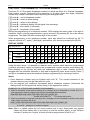
DISPLAY CODES
0
1
2
3
4
5
6
7
8
9
A
B
C
D
E
F
Programming
0
1
2
3
4
5
6
7
8
9
BUSY
{
{
{
{
{
{
{
{
*0
*1
*2
*3
*4
*5
LINE
{
{
{
{
{
{
{
{
REPORT
{
{
{
{
{
{
{
{
TROUBLE
{
{
{
{
{
{
{
{
LED status
Digit programmed
– LED on { – LED off
Using the table above, it is possible to read the entire number which has been programmed
(including command codes) by entering the programmed number function and pressing [#].
Each pressing of the [#] key will show the subsequent digit or code. Number review is
stopped after the sixteenth character or digit and is signaled by three short sounds. Press [*]
and [#] to immediately leave the telephone number programming (or reviewing) function.
Notes:
• Each telephone number must be finished with code "A". The unused elements of the
number memory may also be filled with this code.
• Do not program any additional commands before telephone numbers. Determine the
dialing mode and the signal test before dialing in the appropriate options.
EXAMPLES OF A TELEPHONE NUMBER PROGRAMMING
1. dialer is connected to the public exchange line, message is to be forwarded to number 553 12 71
(the appropriate number programming function has already been selected):
[5][#] [8][#] [5][#] [5][#] [3][#] [1][#] [2][#] [7][#] [1][#] [*][0][#] [*][#]
number end symbol Ê
É to leave the function
2. dialer is connected to the public exchange line, message is to be forwarded to another town (area
code: 0-58), to number 556 40 31:
[0][#] [*][3][#] [5][#] [8][#] [5][#] [5][#] [6][#] [4][#] [0][#] [3][#] [1][#] [*][0][#] [*][#]
É code D – waiting for a continuous signal
Note: After 0 is dialed, before the toll centre answer tone is sent, beep tones may appear
(dialer will finish dialing after 0 and will try to dial the number again). In this situation
instead of "waiting for a signal" a break should be programmed (code E or F).
10
User Manual
DT-1
3. dialer is connected to the internal switchboard line, the message is to be sent to outward office
number 22 628 44 33, the outward office exchange requires pulse dialing and the internal
switchboard a tone dialing, to phone outward office you need to dial 81:
[8][#] [1][#] [*][3][#] [*][1][#] [2][#] [2][#] [6][#] [2][#] [8][#] [4][#] [4][#] [3][#] [3][#] [*][0][#] [*][#]
code D Ê
É code B – switching to pulse dialing
Note: In this case select "tone dialing" as the basic dialing system in the service function
FS3.
Note: To cancel a number, program the number end symbol [*][0][#] (code A) as the first digit
of the number, and leave the number programming function [*][#].
FUNCTION 7 – RECORDING VOICE MESSAGES
Voice messages are recorded by an internal microphone directly after the function is
selected. The message lasts for 30 seconds. When recording the message, speak loudly and
clearly. After finishing the recording, the dialer generates three short sounds.
The message is recorded in the non-volatile memory, which prevents canceling after a power
failure.
EXAMPLE:
[USER'S CODE] [#]
[7]
[#]
say your message
[*]
[0][#]
– activation of the programming mode,
– select function number,
– start message recording,
(you may speak until the dialer signals the end of recording time by three short
sounds),
– press to finish recording earlier,
– leave the programming mode.
If the two-message mode is selected (FS38), recording time is divided between the two
messages. After user's mode is entered ([CODE][#]) and recording function selected ([7][#]),
the dialer generates a short sound and starts the recording of the first message. After
approximately 15 seconds there is a break in the recording, the dialer generates two short
sounds and starts the recording of the second message. After another 15 seconds the
recording is finished and the dialer generates three short sounds, signaling the end of the
function operation.
FUNCTION 8 – MESSAGE CONTROL
To listen to your message, plug in headphones with a Mini Jack to the REPORT OUT socket.
Then select function [8], while being in the user's function programming mode. After pressing
[#], you will hear the message through the headphones (30 seconds). Three short sounds will
signal the end of the message.
If the two-message mode has been selected (two shorter messages lasting for 15 seconds
each), the dialer will play them one by one, separating them with two short sounds and will
finish the function with three short sounds.
FUNCTION 9 – CHANGE OF USER'S CODE
User's code may contain from 4 to 6 digits. Manufacturer's setting (1234) may be changed
with the help of this function.
Programming is very simple: after selecting the function, give the new code and press [#].
EXAMPLE – the programming of code 2468:
[USER'S CODE] [#] – give the old code to enter the programming mode,
[9][#]
– activate the code programming function,
[2][4][6][8]
– give your new code,
DT-1
SATEL
11
– end the programming of the new code,
– leave the programming mode. From now on the new user's code will be used.
[#]
[0][#]
Note: Examples for functions 7 and 9 assumed that the dialer is not in the programming
mode and that it is necessary to leave the mode after finishing a given function. In
normal conditions it is sufficient to enter the programming mode once only and select
all the required functions without the need to leave the programming mode after each
of them.
FUNCTION 0 – LEAVING THE USER'S PROGRAMMING MODE
This function makes it possible for the user to leave the programming mode immediately.
6. PROGRAMMING – SERVICE FUNCTIONS
Service functions are used for the programming of important technical parameters, which
should not be changed by the user. Service code containing from 4 to 6 digits protects
against unauthorized access to programming. Manufacturer's service code is 12345.
Quoting service code and pressing [#] results in the activation of the service mode. In this
mode, the dialer waits for the function number.
Service mode is signaled by short sounds, which are repeated approximately every 4
seconds.
Functions from FS2 to FS8 and FS38 and FS39 define the operation of the dialer. After
entering any of the above functions, LEDs on show which functions are on. The programming
consists in the switching on or off of the appropriate LEDs by pressing digit key with the LED
number. After all options are set in a given function, confirm the settings by pressing [#].
Functions from FS15 to FS33 are used for the programming of data connected with the
monitoring.
FS0 – LEAVING THE SERVICE MODE
In contrast to the user programming mode, service mode does not automatically switch off if
keys are not pressed. To leave service mode, press function 0.
FS1 – CHANGE OF SERVICE CODE
Service code is programmed in the same way as user's code.
EXAMPLE: change of service code to 456789 (service mode is already on):
[1][#]
[4][5][6][7][8][9]
[#]
– select the function
– enter digits making the code
– end of code recording – leave the function
FS2 – INPUT OPTIONS
LED
BUSY
LINE
REPORT
TROUBLE
on
off
on
off
on
off
on
off
Option
ALARM input reacts to short to ground
ALARM input reacts to separation from ground
ARMED input reacts to short to ground
ARMED input reacts to separation from ground
AUX input reacts to short to ground
AUX input reacts to separation from ground
ALARM input reacts after 0.1 second
ALARM input reacts after 1 second
Control key
4
3
2
1
12
User Manual
DT-1
FS3 – PHONING OPTIONS (PART I)
LED
BUSY
LINE
REPORT
TROUBLE
on
off
on
off
on
off
on
off
Option
dialing disabled (does not apply to monitoring)
dialing enabled
tone dialing
*
pulse dialing
*
message play time: 60 seconds
message play time: 30 seconds
AUX input also activates forwarding messages by telephone
AUX input only sends messages to the monitoring station
Control key
4
3
2
1
Notes:
• Option 3 (marked with *) defines the basic dialing mode. The dialer starts the dialing in
accordance with the setting of this option. If a part of the number is to be dialed according
to one standard, and the remaining part according to another, set the basic dialing mode
as the one required for the first part of the number, and enter a command to switch to the
other standard in the telephone number.
• When the dialer operates in the mode with one 30-second message, the lighting of LED 2
will result in the message being played twice. In the two-message mode (each lasting for
15 seconds) the setting of option 2 will decide whether the message will be played twice
(LED 2 off) or four times (LED 2 on).
• Option 1 must be selected (LED 1 on) in the two-message mode.
FS4 – PHONING OPTIONS (PART II)
LED
BUSY
LINE
REPORT
TROUBLE
on
off
on
off
on
off
on
off
Option
answering external phone calls enabled
answering external phone calls disabled
breakdown sound signal enabled
breakdown sound signal disabled
telephone exchange answer signal testing disabled
telephone exchange answer signal testing enabled
control of signal after dialing disabled
control of signal after dialing enabled
Control key
4
3
2
1
Notes:
• Despite the enabling of option 4, external phone answering function may be inactive, as
the status of the ARM input is also important. Before enabling the option, specify after how
many rings the dialer is to answer phones (FS12). Detailed description of this function is
given in the section "DIALER ANSWERS PHONES ".
• The dialer may signal the discovery of a trouble by a sound signal that will be repeated
every 4 seconds. Option 3 will disable the function.
• When option 2 is disabled, the dialer dials a number after 5 seconds since "the receiver is
picked up". When it is enabled, dialing starts after the dialer receives the continuous tone
of the telephone exchange. If due to non-continuous signal the dialer is unable to dial, an
error is reported.
• Option 1 controls the telephone answering test. When it is disabled, the dialer sends a
message after 16 seconds since the dialing of the number (in the first round after 8
seconds). This option concerns mainly the playing of voice messages. For message
forwarding to pagers and for monitoring, the dialer tests telephone answering according to
additional criteria (answer tone of the station or the pager system exchange).
DT-1
SATEL
13
• Options 3 from FS3 and 2 and 1 from FS4 also concern monitoring. If after dialing the
signals received are not typical and the control of these signals is disabled, the dialer will
wait for an answer tone from the monitoring station for 60 seconds. Data will be sent after
the station answer tone is correct.
FS5 – MONITORING OPTIONS
The options programmed with the help of this function determine the way in which messages
will be forwarded to monitoring stations. The appropriate combination of options 3, 2 and 1
will make it possible to obtain the appropriate message forwarding mode.
LED
BUSY
LINE
REPORT
TROUBLE
Option
on
off
on
off
on
off
on
off
monitoring disabled
monitoring enabled
transmission to two monitoring stations
transmission to one monitoring station
transmission with event distribution (SPLIT REPORTING)
transmission without event distribution
transmission to station two if station one is unavailable
transmission only to station one
Control key
4
3
2
1
Notes:
• Depending on the option, 2 events will be sent to station 1 or station 2, or both of them.
When option 3 is on, the status of option 2 does not matter.
• Transmission with event distribution (option 2) consists in the sending of codes of alarm
events to the first monitoring station, and all other codes to the second station.
• Option 1 is taken into consideration when option 3 is switched off.
FS6 – SPECIFICATION OF NUMBERS FOR PAGER SYSTEM (PART I)
LED
BUSY
LINE
REPORT
TROUBLE
on
off
on
off
on
off
on
off
Option
telephone number 4 to be used for forwarding messages to pager
telephone number 4 to be used for forwarding voice messages
telephone number 3 to be used for forwarding messages to pager
telephone number 3 to be used for forwarding voice messages
telephone number 2 to be used for forwarding messages to pager
telephone number 2 to be used for forwarding voice messages
telephone number 1 to be used for forwarding messages to pager
telephone number 1 to be used for forwarding voice messages
Control key
4
3
2
1
Note: For numbers selected in this function, the dialer automatically tests signals from the
telephone line after dialing the number in order to discover answer tones from the
pager system centre (also when analysis of dial signals is disabled – option 1 in FS4).
After receiving the correct dialing tone, the message recorded in the dialer memory is
sent. The other numbers may be given for pager by FS39.
FS7 – DISABLING USER FUNCTIONS (PART I)
LED
BUSY
LINE
REPORT
TROUBLE
Option
on
off
on
off
on
off
on
off
user function 4 disabled
user may change the telephone number programmed by function 4
user function 3 disabled
user may change the telephone number programmed by function 3
user function 2 disabled
user may change the telephone number programmed by function 2
user function 1 disabled
user may change the telephone number programmed by function 1
Control key
4
3
2
1
14
User Manual
DT-1
FS8 – DISABLING USER FUNCTIONS (PART II)
LED
BUSY
LINE
REPORT
TROUBLE
on
off
on
off
on
off
on
off
Option
keypad disabled when ARMED
keypad enabled regardless of ARMED status
user may not change the message programmed by F7
user may change the message programmed by F7
user function 6 disabled
user may change the telephone number programmed by function 6
user function 5 disabled
user may change the telephone number programmed by function 5
Control key
4
3
2
1
Note: It is possible to disable the dialer keypad for the time when the alarm system is on. To
do so, supply the signal informing about the system activation to ARM input and
activate option 4.
FS9 – PROGRAMMING OF THE REAL TIME CLOCK
It is necessary to set the clock if the dialer is to phone the monitoring station to carry out
standard transmission test. Time is programmed in the sequence hours: minutes. Confirm
each digit by pressing [#].
EXAMPLE: programming of 12:45 (service mode is already on):
[9][#]
[1][#]
[2][#]
[4][#]
[5][#]
– select function,
– enter the first hour digit,
– enter the second hour digit,
– enter the first minute digit,
– enter the second minute digit; leave the function after pressing [#]
Note: During the programming, LEDs show (in binary code) the subsequent digits of the
current dialer time.
FS10 – SETTING TIME FOR THE SENDING OF A TEST CODE TO STATION
The dialer may send the test code to the monitoring station every day at the same time.
Function FS10 makes it possible to set the time at which the test is to be sent.
If you enter a digit, which is not customary to the clock (e.g. 99:99), you will disable the test
code sending function. Programming is the same as for function FS9.
FS11 – THE NUMBER OF DIALING ROUNDS AND CONNECTION ATTEMPTS IN A
ROUND
This function programs the following two parameters ruling the effectiveness of message
forwarding (dialing):
• number of dialing rounds – from 1 to 9 (the more the bigger chance for successful
connection). Selecting 0 disables the message forwarding function.
• number of connection attempts in a round (from 1 to 9) – if zero is entered, four
connection attempts will be made automatically. This parameter has been introduced to
prevent blocking the line by continuous dialing of an inaccessible number (when no one
answers the telephone or if the dialer receives busy tone all the times, etc.).
Programming consists in entering two digits one after the other and confirming each of them
by pressing [#]. The first digit will stand for the number of dialing rounds and the
second one for the number of dialing attempts if there is no connection.
EXAMPLE: programming of 2 dialing rounds and 3 connection attempts for each round (service mode
is already on):
[1][1][#]
– select function,
[2]
– give the number of rounds,
DT-1
[#]
[3]
[#]
SATEL
15
– confirm digit one,
– give the number of dialing attempts in each round,
– confirm digit one – you will then automatically leave the function.
Note: The number of rounds must be bigger than 0 in order for the message forwarding to be
effective.
FS12 – NUMBER OF RINGS BEFORE ANSWERING
This function specifies after how many rings the dialer answers phones, providing information
on alarm system status. Programming is as for function 11. Programming zero disables the
telephone answering function.
Note: If there are devices such as answering system or fax connected to the line behind the
dialer, program a smaller number of rings for dialer than for the other devices.
FS13 – PROGRAMMING OF THE TELEPHONE NUMBER OF THE FIRST MONITORING
STATION
FS14 – PROGRAMMING OF THE TELEPHONE NUMBER OF THE SECOND
MONITORING STATION
These functions determine the telephone numbers of the monitoring stations to which
information on events taking place in the system is to be forwarded.
The programming of the numbers is the same as for user functions (see description of
functions F1 to F6).
FS15 – PROGRAMMING OF IDENTIFIER FOR THE FIRST MONITORING STATION
FS16 – PROGRAMMING OF IDENTIFIER FOR THE SECOND MONITORING STATION
Identifier is the identification number of the alarm system communicating with the monitoring
station. It may be composed of three or four characters (from 1 to F HEX), without zeros in
the middle. A three-digit identifier has to be finished with zero (as the fourth character).
EXAMPLE: programming of identifier 1F30
[1][5][#]
[1]
[#]
– select function (LEDs will show the code of the first identifier digit),
– enter the first digit of the new identifier (1 will be shown on LEDs),
– accept the first digit of the new identifier (LEDs will show the code of the second
[*][5][#]
[3][#]
[0][#]
identifier digit),
– enter code "F" – the second digit of the new identifier,
– enter the third digit of the identifier,
– enter the fourth digit of the identifier (after pressing [#] you will leave the function).
FS17 – SELECTION OF TRANSMISSION FORMAT FOR THE FIRST MONITORING
STATION
FS18 – SELECTION OF TRANSMISSION FORMAT FOR THE SECOND MONITORING
STATION
Transmission format should be agreed with the operators of the monitoring station. If
possible, use the fastest formats (7-Ademco Express as DTMF is the fastest; in pulse formats
6-Radionics 2300 with parity is the fastest and 0-Silent Knight the slowest; "extended"
formats are almost twice slower).
Enter one character from the range 0 to C, as described below. Confirm your selection by
pressing [#].
TRANSMISSION FORMATS:
0 – Silent Knight, Ademco slow (1400Hz/10Bps)
1 – Sescoa, Franklin, DCI, Vertex (2300Hz/20Bps)
16
User Manual
2
3
4
5
6
7
8
9
A
B
C
–
–
–
–
–
–
–
–
–
–
–
DT-1
Silent Knight fast (1400Hz/20Bps)
Radionics 1400Hz
Radionics 2300Hz
Radionics with parity 1400Hz
Radionics with parity 2300Hz
Ademco Express (DTMF)
Silent Knight, Ademco slow, extended
Sescoa, Franklin, DCI, Vertex, extended
Silent Knight fast, extended
Radionics 1400Hz, extended
Radionics 2300Hz, extended
FS19 – ALARM CODE PROGRAMMING
This function defines the code to be sent to the station when the ALARM input records
"alarm" status (alarm status is defined by the option in FS2).
EXAMPLE:
[1][9][#]
[1][#]
[3][#]
programming of a code equal to 13 (service mode is already on)
– select function,
– enter the first code character,
– enter the second code character (after pressing # you will leave the function).
FS20 – ALARM RESTORE CODE PROGRAMMING
This function defines the code to be sent to the monitoring station when the ALARM input
records the disappearance of the "alarm" status (alarm status is defined by the option in
FS2).
FS21 – ARM CODE PROGRAMMING
This function defines the code to be sent to the station when the "on" status signal is
delivered to the ARM input (in consistence with the option selected in FS2).
FS22 – DISARM CODE PROGRAMMING
This function defines the code to be sent to the station when the "off" status signal is
delivered to the ARM input (in consistence with the option selected in FS2).
FS23 – AUX1 CODE PROGRAMMING
Any function may be ascribed to the AUX input. An additional alarm or control signal may
also be supplied to it. The code programmed in this function is sent whenever the status to
which the input is to react reaches the input (option in FS2).
FS24 – AUX0 CODE PROGRAMMING
The code programmed in this function is sent whenever the AUX input receives a status,
which is opposite to the one to which the input is to react (option in FS2).
FS25 – TRANSMISSION TEST CODE PROGRAMMING
The code programmed in this function is sent whenever the time on the dialer clock is the
same as that programmed by the function FS10.
FS26 – TLM TROUBLE CODE PROGRAMMING
Whenever there is an event about which the monitoring station should be informed, the dialer
starts dialing the telephone number of the station. When the station is unavailable (e.g. due
to busy tone), the dialer will try to make a connection six more times. When all the attempts
are unsuccessful, it stops dialing for a minute. After that the cycle is started again. The TLM
TROUBLE code is sent as the first one, when the dialer manages to make a connection after
such a break.
DT-1
SATEL
17
FS27 – PROGRAMMING OF THE CODE "OVERLOADING OF STATION 1 BUFFER
MEMORY"
FS28 – PROGRAMMING OF THE CODE "OVERLOADING OF STATION 2 BUFFER
MEMORY"
When the monitoring station does not reply for a long time, the events are recorded in dialer
buffer memory. If the number of events exceeds the buffer memory, the oldest event will be
deleted. After establishing connection with the station, and transferring the all events filling
the buffer memory, the code "buffer memory overloading" will also be additionally sent.
FS29 – KEYPAD ALARM DEACTIVATION CODE PROGRAMMING
If the dialer forwards messages to numbers programmed by user functions, entering user's
code (and pressing #) will stop the process. It is then that the code programmed by this
function is sent.
FS30 – PROGRAMMING ACTIVATION CODE PROGRAMMING
This code is sent whenever user programming mode is activated.
FS31 – SERVICE MODE ACTIVATION CODE PROGRAMMING
FS32 – SERVICE MODE LEAVING CODE PROGRAMMING
FS33 – DIALER RESTART CODE PROGRAMMING
This code is sent upon the restarting of the dialer processor system (e.g. after the power is
turned on after end of a power failure).
Note: Event codes should be agreed with the operators of the monitoring station. Programming consists in entering two characters from the range 0 to F. Each character
should be confirmed by [#]. For formats 3/1 and 4/1, zero should be entered as the
second character. Events with the code 00 (two zeros) will not be sent.
FS34 – PROGRAMMING MESSAGE "A" TO PAGER SYSTEM
The dialer may forward messages to one of three pager systems, i.e. POLPAGER,
TELEPAGE or EASY-CALL. Automatic pager system exchanges forward messages in
various ways. That is why it is necessary to get acquainted with the user's guide on a given
pager before programming. It is also recommended to carry out a test by sending a message
by a dial tone telephone (DTMF).
For example, in order to send the "ALARM997" message to POLPAGER, you should press
the following keys after connecting the exchange:
MESSAGE (for POLPAGER system)
KEYS
select text mode
[*][*]
A
[2][*]
L
[5][#]
A
[2][*]
R
[7]
M
[6][*]
select numeric mode
[0][#]
9
[9]
9
[9]
7
[7]
message end
[#]
During a response to an alarm, after connecting the exchange of the pager system, the dialer
simulates the pressing of keys on the keypad dial.
18
User Manual
DT-1
To program a message, enter codes of the subsequent keys, which should be pressed if the
message was sent by phone. Confirm each code by pressing [#] (as during telephone
number programming). The dialer is able to store 96 codes.
Notes:
• digits have codes consistent with their value (from 0 to 9),
• the [#] key on the dial is coded as "A" (see: table of monitor codes),
• the [*] key on the dial is coded as "B",
• a 3-second break is coded as "E",
• message programming should be finished with an additional character "F" (which informs
the dialer that if the pager system requires a symbol ending a message, it should be
programmed as required by the system, and add the end symbol for the dialer).
EXAMPLE: PROGRAMMING A MESSAGE TO POLPAGER:
Message
select text mode
A
L
A
R
M
switch to numeric mode
9
9
7
message end (information
for POLPAGER exchange)
message end (for dialer)
leave programming mode
Keys used during the
sending of the message
by phone
**
2*
5#
2*
7
6*
0#
9
9
7
Codes entered
to dialer
Keys used in the dialer to
enter data
BB
2B
5A
2B
7
6B
0A
9
9
7
[*][1][#][*][1][#]
[2][#][*][1][#]
[5][#][*][0][#]
[2][#][*][1][#]
[7][#]
[6][#][*][1][#]
[0][#][*][0][#]
[9][#]
[9][#]
[7][#]
A
[*][0][#]
F
[*][5][#]
[*][#]
Codes entered
to dialer
Keys used in the dialer to
enter data
#9
2*
5#
2*
70
6*
#
9
9
7
22357
E
A9
2B
5A
2B
70
6B
A
9
9
7
[2][#][2][#][3][#][5][#][7][#]
[*][4][#]
[*][0][#][9][#]
[2][#][*][1][#]
[5][#][*][0][#]
[2][#][*][1][#]
[7][#][7][#]
[6][#][*][1][#]
[*][0][#]
[9][#]
[9][#]
[7][#]
#*
AB
[*][0][#][*][1][#]
F
[*][5][#]
[*][#]
#
EXAMPLE: PROGRAMMING A MESSAGE TO TELEPAGE:
Message
pager number (e.g. 22357)
3-second break
select text mode
A
L
A
R
M
switch to numeric mode
9
9
7
message end (information
for POLPAGER)
message end (for dialer)
leave programming mode
Keys used during the
sending of the message
by phone
22357
DT-1
SATEL
19
Note: In the TELEPAGE system, when the pager number is composed of 4 digits, it may be
given together with the exchange number. If the number is composed of 5 digits, add
0001 to exchange number (i.e. program 0D98250001A in the user's function), and give
pager number at the beginning of the message.
FS35 – PROGRAMMING MESSAGE "A" TO POLPAGER
This function facilitates the programming of messages sent in the POLPAGER system. To
program, press keys in the same way as when forwarding a message by a dial tone
telephone. The dialer analyses the data entered in exactly the same way as the exchange of
the POLPAGER system and after recognizing the end of the message it leaves the function.
Entering text is facilitated by letters placed on the dialer keypad dial. The distribution of letters
is the same for all systems.
In the POLPAGER system, if you want to select a letter located in the centre of a line of
letters, press the key bearing the letter. If you want to select the letter on the left, press the
key and [*]. If you want to use the letter on the right, press the key and [#].
EXAMPLES:
letter B – press
letter P – press
letter F – press
[2]
[7][*]
[3][#]
To have a space between characters in the text mode, press [0], and if you want to use a
dash, press [0] and [*].
After selecting the function, the dialer enters the numeric mode. To switch to text mode, enter
[*][*], and to switch to numeric mode enter [0][#]. To end the message, press [#] (the dialer
has to be in the numeric mode).
EXAMPLE: programming message: PROBLEM – GAS
[3][5][#] – select function (REPORT diode is flashing showing dialer's readiness to accept message),
[*][*]
– switch to text mode
[7][*]
– enter letter P
[7]
– enter letter R
[6][#]
– enter letter O
[2]
– enter letter B
[5][#]
– enter letter L
[3]
– enter letter E
[6][*]
– enter letter M
[0]
– enter space
[0][*]
– enter dash
[0]
– enter space
[4][*]
– enter letter G
[2][*]
– enter letter A
[7][#]
– enter letter S
[0][#]
– switch to numeric mode
[#]
– message end (confirmed by three short sounds)
FS36 – RESTORATION OF MANUFACTURER'S SETTINGS
This function restores manufacturer's settings. After selecting this function, the dialer waits for
a confirmation of your decision to restore settings ([#]) or for your resignation ([*]).
After finishing this function, settings on the dialer will be as follows:
– user's code: 1234,
– service code: 12345,
– module identifier – FFFF,
– computer identifier – FFFF,
– telephone numbers not programmed,
20
–
–
–
–
–
–
–
–
–
–
–
–
User Manual
DT-1
tone dialing,
number of rounds – 0 (messaging blocked),
maximum number of retries in 1 round – 1
number of rings before answer – 0,
monitoring stations telephone numbers not programmed,
monitoring stations identifiers not programmed,
transmission format– Ademco slow (10 BPS),
all monitoring codes equal to zero,
phoning and monitoring disabled,
pager answer parameters – signal for GSM-4 / GSM LT modules,
message A – ALARM-WE.ALM,
message B – ALARM-WE.AUX.
EXAMPLE: restoration of manufacturer's settings.
[3][6][#] – select function.
All dialer LEDs are flashing – the dialer waits for confirmation of the function or resignation from the
restoration of manufacturer's settings
– confirm the restoration of manufacturer's settings – the dialer will generate one short sound
[#]
followed by three short sounds, confirming that manufacturer's settings have been restored.
FS37 – PROGRAMMING PARAMETERS OF THE PAGER SYSTEM STATION SIGNAL
Pager systems have different answer tone signal parameters. The dialer is unable to work
with several systems at the same time. This function makes it possible to program the
parameters of the signal of the system the dialer is to interact with.
To program the parameters, enter 12 characters describing the parameters of the signal of
the selected pager system in consistence with the table below. Every character must be
confirmed by [#].
POLPAGER
TELEPAGE
EASY CALL
8
B
7
1
2
3
B
E
D
1
2
3
5
E
7
1
0
0
8
4
B
1
1
0
0
0
6
0
3
B
4
A
8
0
3
C
Note: After the settings are restarted by FS36, the dialer will be prepared to work with
POLPAGER. As POLPAGER changed the dialing tone in some station, it is
occasionally necessary to program different handshaking signal parameters.
FS38 – TELEPHONING AND MONITORING OPTIONS
LED
BUSY
Option
on
off
on
LINE
off
REPORT
on
off
pulse duty factor 1:1.5
pulse duty factor 1:2
resignation from sending the code to the monitoring station after
8 unsuccessful attempts (no answer)
stopping the monitoring for 30 minutes after 8 unsuccessful attempts to
send the code (no answer)
two messages
one message
Control key
4
3
2
LED 1 (trouble) does not matter.
Note: Selecting the two-message mode (LED 2 on) results in ascribing telephone numbers
to message numbers on a permanent basis, as described in the chapter "About DT-1”.
This work mode also applies to the forwarding of messages to pager systems.
DT-1
SATEL
21
FS39 – ENTERING NUMBERS SELECTED FOR A PAGER SYSTEM (PART II)
LED
REPORT
TROUBLE
on
off
on
off
Option
telephone number 6 for message forwarding through pager
telephone number 6 for voice message forwarding
telephone number 5 for message forwarding through pager
telephone number 5 for voice message forwarding
Control key
2
1
See description of function FS6.
FS40 – PROGRAMMING MESSAGE "B" TO PAGER SYSTEM
FS41 – PROGRAMMING MESSAGE "B" TO POLPAGER
These two functions are used for the programming of the second message to the pager
system station if the dialer works in the two-message mode. See description of functions
FS34 and FS35.
FS42 – PROGRAMMING DIALER IDENTIFIER
FS43 – PROGRAMMING COMPUTER IDENTIFIER
The dialer and computer identifiers serve to identify interfaced devices. They both have
hexadecimal form (digits and letters from A to F – see: Display codes) and consist of 4
characters. Communication between the program and the dialer is only possible, when the
identifier entered in the corresponding field in the program is consistent with that saved in the
dialer. On the first-time establishing of communication, the program will automatically
generate a random identifier for the dialer and save it into the device memory, while leaving
the computer identifier unchanged. The two identifiers can be saved into to the configuration
file. It is advisable to change both identifiers to protect the dialer settings from any
unauthorized modifications. When the communication is established again, the program will
be browsing through the available configuration files. If it finds one with identifiers
corresponding to the dialer data, it will suggest opening it.
When programming the identifier manually in the dialer, confirm each character by pressing
[#]. In the DT-1 program, identifiers can be entered without being confirmed by additional
characters.
RESTARTING DIALER
It is possible to select service mode and restore default settings without knowing the service
code. In order to do so:
• switch off the power,
• place a jumper on dialer board RESET pins,
• switch on the power (the dialer should confirm activation of the service mode by four short
sounds followed by one long sound),
• remove the jumper from RESET pins and select function FS36.
7. PROGRAMMING AND CONFIGURING THE DIALER WITH DT-1 PROGRAM
The dialer can be programmed and configured by using the DT-1 program, which is delivered
free of charge with the device. Communication between the program and the dialer takes
place locally. The computer COM port must be connected to the RS-232 (TTL) port on the
dialer electronics board. Cables for making this connection possible are available as a set
designated DB9FC/RJ-KPL.
In order to establish communication between the dialer and the computer, do as follows:
1. Connect the dialer RS-232 port and the computer COM port with a suitable cable.
22
User Manual
DT-1
2. Start the DT-1 program.
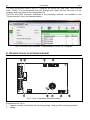
3. Click the "Configuration" button (see Fig. 2 and explanations thereto).
4. In the "Connection" window that will be displayed, select the computer COM port to which
the cable is connected. The program will establish communication with the dialer.
Fig. 1. "Connection" window in the DT-1 program.
7.1 MAIN MENU
Fig. 2. Main menu of the DT-1 program.
Explanations for Fig. 2:
1 - Load file – the button enables loading data file.
2 - Save file – the button enables saving configuration data to file.
3 - Download – the button enables downloading data from the dialer.
4 - Upload – the button enables uploading data to the dialer.
5 - Abort – use this button to terminate the data reading/writing process.
6 - Configuration – the button opens the "Connection" window, where you can select the
computer COM port, through which programming is to be effected.
7 - Connection – click the button to enable/disable the computer COM port (programming
through the RS-232 port);
The button number indicates the current communication status:
–
8
9
10
11
12
-
– green color – computer COM port enabled;
–
– gray color – computer COM port disabled.
information on COM port number.
dialer name.
dialer program version (build number and compilation date).
dialer actual time.
if any problems related to connection to telephone line are found, the
displayed to indicate the trouble.
icon will be
DT-1
SATEL
23
7.2 MAIN WINDOW OF DT-1 PROGRAM
Fig. 3. Main window of the DT-1 program.
The DT-1 program enables programming most of the user functions and all of the dialer
service functions. All the options are described in detail in sections referring to particular
functions.
24
User Manual
DT-1
The user and service codes in the DT-1 program are factory set (user code: 1234, service
code: 12345). It is recommended that you change both codes the first time you run the
program, and save them to the configuration file.
The FS9 and FS36 functions, described in the preceding sections, are available in the
"Communication" menu, as illustrated below.
Fig. 4. FS9 and FS36 functions, "Communication" menu, DT-1 program.
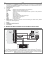
8. DESCRIPTION OF ELECTRONICS BOARD
Fig. 5. View of the dialer electronics board.
Explanations for Fig. 5:
1 - tamper contact, activated by the housing opening / tearing off the mounting surface.
2 - relay.
DT-1
SATEL
25
3 - RS-232 port (TTL standard) enabling the dialer to be connected to the computer (the
connection can be made by using the cables available in a set manufactured by SATEL
and designated DB9FC/RJ-KPL).
4 - keypad socket.
5 - terminals:
T-1; R-1
- telephone line output (telephone set connection).
TIP; RING
- telephone line input (analog trunk line).
- protective terminal of the telephone dialer (connect to the protection
circuit only).
TMP
- tamper circuit.
ALM
- alarm signal input.
ARM
- alarm system armed mode signal input.
AUX
- additional alarm signal input.
+12V
- power supply input.
COM
- common ground.
6 - RESET pins for starting the service mode and restoring the dialer factory default
settings (see: Restarting dialer).
7 - buzzer.
8 - headphones socket terminal.
9 - microphone.
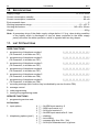
9. EXAMPLE OF DIALER CONNECTION TO CA-4V1 CONTROL PANEL
Fig. 6. Way of connecting the DT-1 dialer to the CA4V1 alarm control panel. The control
panel OUT2 output indicates the armed mode (activation means that the output is shorted to
ground), and the OUT1 output controls the SPL-2010 acoustic signaling. The dialer ALM and
ARM inputs react to being shorted to ground.
26
User Manual
DT-1
10. SPECIFICATIONS
Supply voltage ................................................................................................... 12 V DC ±15%
Current consumption, standby .........................................................................................30 mA
Current consumption, maximum ......................................................................................80 mA
Environmental class .................................................................................................................II
Working temperature range ....................................................................................-10...+55 °C
Housing dimensions...................................................................................... 145 x 90 x 38 mm
Weight............................................................................................................................... 203 g
Note: A momentary drop of the dialer supply voltage below 11V (e.g. when testing condition
of the battery which is discharged or has not been connected to the dialer supply
panel) will restart the dialer operation, which is signaled with two long beeps.
11. LIST OF FUNCTIONS
USER FUNCTIONS
1 programming of telephone number 1
(16 characters, to disable use FS7)
|_|_|_|_|_|_|_|_|_|_|_|_|_|_|_|_|
2 programming of telephone number 2
(16 characters, to disable use FS7)
|_|_|_|_|_|_|_|_|_|_|_|_|_|_|_|_|
3 programming of telephone number 3
(16 characters, to disable use FS7)
|_|_|_|_|_|_|_|_|_|_|_|_|_|_|_|_|
4 programming of telephone number 4
(16 characters, to disable use FS7)
|_|_|_|_|_|_|_|_|_|_|_|_|_|_|_|_|
5 programming of telephone number 5
(16 characters, to disable use FS8)
|_|_|_|_|_|_|_|_|_|_|_|_|_|_|_|_|
6 programming of telephone number 6
(16 characters, to disable use FS8)
|_|_|_|_|_|_|_|_|_|_|_|_|_|_|_|_|
7
8
9
0
recording message (this function may be disabled by service function FS8)
message control
code programming
leaving the programming mode
SERVICE FUNCTIONS
1 programming service code
bit functions
2 input options
3 telephoning options (part I)
4
3
2
1
4
3
2
1
|_| – ALARM input reacts to 0
|_| – ARM input reacts to 0
|_| – AUX input reacts to 0
|_| – ALARM input reacts after 0.1 sec.
|_| – disabling
|_| – tone dialing
|_| – message play time 32s (16s)
|_| – AUX input forwards mess. by phone
DT-1
SATEL
4 telephoning options (part II)
5 monitoring options
6 telephone numbers to
pager systems
7 to disable functions 1 to 4
8 to disable functions 5 to 7
4
3
2
1
4
3
2
1
4
3
2
1
4
3
2
1
4
3
2
1
27
|_| – answering phones activated
|_| – sound signalling of problems
|_| – omit signal test before dialing
|_| – omit signal test after dialing tel. no.
|_| – disabling
|_| – transmission to two monitoring stations
|_| – event distribution (SPLIT REPORTING)
|_| – transmission to station 2, when 1 unavailable
|_| – telephone number 4 = pager number
|_| – telephone number 3 = pager number
|_| – telephone number 2 = pager number
|_| – telephone number 1 = pager number
|_| – to disable user function 4
|_| – to disable user function 3
|_| – to disable user function 2
|_| – to disable user function 1
|_| – to disable keypad if ARM
|_| – to disable user function 7
|_| – to disable user function 6
|_| – to disable user function 5
character functions
9
10
11
12
13
14
15
16
17
18
clock
|_|_|_|_|
test code sending time
|_|_|_|_|
no. of rounds and connection attempts in a round |_|_|
(0–9;0–9)
no. of rings before answering
|_|
(0–9)
station 1 number (16 characters)
|_|_|_|_|_|_|_|_|_|_|_|_|_|_|_|_|
station 2 number (16 characters)
|_|_|_|_|_|_|_|_|_|_|_|_|_|_|_|_|
identifier for station 1
|_|_|_|_|
identifier for station 2
|_|_|_|_|
transmission format for station 1
|_|
transmission format for station 2
|_|
0 – Silent Knight,Ademco slow (10 BPS)
1 – Sescoa,Franklin,DCI,Vertex (20 BPS)
2 – Silent Knight fast(1400Hz/20Bps)
3 – Radionics 1400Hz
4 – Radionics 2300Hz
5 – Radionics 1400Hz with parity
6 – Radionics 2300Hz with parity
19
20
21
22
23
24
ALARM code
ALARM RESTORE code
ARM code
DISARM code
AUX1 code
AUX0 code
7 – Ademco Express (DTMF)
8 – Silent Knight,Ademco slow (10 BPS) ext.
9 – Sescoa,Franklin,DCI,Vertex(20 BPS) ext.
A – Silent Knight fast extended
B – Radionics 1400Hz extended
C – Radionics 2300Hz extended
|_|_|
|_|_|
|_|_|
|_|_|
|_|_|
|_|_|
(*)
(*)
(**)
(**)
(***)
(***)
28
25
26
27
28
29
30
31
32
33
User Manual
transmission test code
TLM TROUBLE code
stat. 1 buffer mem. overload code
stat. 2 buffer mem. overload code
alarm switched off from keypad code
programming switched on code
service mode switched on code
service mode switched off code
dialer RESTART code
DT-1
|_|_|
|_|_|
|_|_|
|_|_|
|_|_|
|_|_|
|_|_|
|_|_|
|_|_|
(**)
(**)
(**)
(**)
(**)
(**)
(**)
(**)
(**)
(*)
in SPLIT REPORTING mode codes sent to station 1
(**) in SPLIT REPORTING mode codes sent to station 2
(***) in SPLIT REPORTING mode codes sent to station 1 (when AUX input reports alarm – option 1
turned on in service function FS3), if AUX is not an alarm input, codes are sent to station 2.
34 programming message A with processing (max. 96 key codes)
|_|_|_|_|_|_|_|_|_|_|_|_|_|_|_|_|_|_|_|_|_|_|_|_|_|_|_|_|_|_|_|_|
|_|_|_|_|_|_|_|_|_|_|_|_|_|_|_|_|_|_|_|_|_|_|_|_|_|_|_|_|_|_|_|_|
|_|_|_|_|_|_|_|_|_|_|_|_|_|_|_|_|_|_|_|_|_|_|_|_|_|_|_|_|_|_|_|_|
35 programming message A to POLPAGER (standard)
36 programming default settings
37 parameters of dialing tone of the pager system exchange
|_|_|_|_|_|_|_|_|_|_|_|_|
bit functions
38 telephoning and
monitoring options
4
3
2
2
1
39 telephone numbers to
pager systems (ctd.)
|_| – pulse duty factor 1:1.5
|_| – resignation from sending code after 8 attempts
|_| – two messages
|_| – telephone number 6 = pager number
|_| – telephone number 5 = pager number
character functions
40 programming message B with processing (max. 96 key codes)
|_|_|_|_|_|_|_|_|_|_|_|_|_|_|_|_|_|_|_|_|_|_|_|_|_|_|_|_|_|_|_|_|
|_|_|_|_|_|_|_|_|_|_|_|_|_|_|_|_|_|_|_|_|_|_|_|_|_|_|_|_|_|_|_|_|
|_|_|_|_|_|_|_|_|_|_|_|_|_|_|_|_|_|_|_|_|_|_|_|_|_|_|_|_|_|_|_|_|
41 programming message B to POLPAGER (standard)
42 programming dialer identifier
|_|_|_|_|
43 programming computer identifier
|_|_|_|_|
DISPLAY CODES
0
1
2
3
4
5
6
7
8
9
A
B
C
D
E
F
Programming
0
1
2
3
4
5
6
7
8
9
BUSY
{
{
{
{
{
{
{
{
*0
*1
*2
*3
*4
*5
LINE
{
{
{
{
{
{
{
{
REPORT
{
{
{
{
{
{
{
{
TROUBLE
{
{
{
{
{
{
{
{
LED status
Digit programmed
– LED on { – LED off
DT-1
SATEL
29
CODES CONTROLLING PROGRAMMING IN TELEPHONE NUMBERS
[*][0] code A – end of telephone number
[*][1] code B – switch to pulse dialing
[*][2] code C – switch to tone dialing
[*][3] code D – additional waiting for the signal from exchange
[*][4] code E – short break (3 seconds)
[*][5] code F – long break (10 seconds)
Note: Do not program additional commands before telephone number. Determine dialing
mode and signal test before dialing using the appropriate options. Finish each
telephone number with "A".
12. HISTORY OF THE MANUAL UPDATES
The updates below apply to the manual drawn up for the equipment manufactured up to
March 2000.
Date
Description of changes
2000-03-07
DT-1
• FS38 service function added – options of LEDs 4 and 3 (BUSY and LINE) .
• FS11 function is supplemented by another parameter: „Number of dialing attempts in
a round”.
• A new format of data transmission to the monitoring station is added (FS17 & FS18)
i.e. ADEMCO EXPRESS (DTMF) and numeration of the transmission format list is
changed.
TRANSMISSION FORMATS valid until 07-03-2000.
0 Silent Knight, Ademco slow (10 BPS)
1 Sescoa, Franklin, DCI, Vertex (20 BPS)
2 Silent Knight fast
3 Radionics 1400
4 Radionics 2300
5 do not program
6 Radionics 1400 with parity
7 Radionics 2300 with parity
8 Silent Knight, Ademco slow (10 BPS) extended
9 Sescoa, Franklin, DCI, Vertex (20 BPS) extended
A Silent Knight fast extended
B Radionics 1400 extended
C Radionics 2300 extended
D do not program
E Radionics 1400 with parity extended
F Radionics 2300 with parity extended
2001-01-31
DT-1 plus
• Ann option to record and send two messages (8 seconds each) has been introduced.
• A third option has been introduced to FS38 function (LED 2 option – REPORT).
• Service functions added: FS39, FS40 and FS41.
2004-03-15
DT-1 plus
• A section on the costs incurred by the dialer user has been added (p. 3).
• Information that the reporting function starts only with the ARM zone active, i.e. when
the alarm system is armed, has been deleted (p. 3, 6).
• The time when the dialer remains in the user function mode without pressing any
keys has been changed to 120s (from 40s) (p. 8).
• A remark on the dialer restarting has been added (p. 26).
2004-06-15
• An illustration of PCB for laminate in version 3.1 (p. 24)
2006-05-12
DT-1
• The earlier symbol of DT-1 device and the new program version number is added on
the cover.
30
User Manual
2009-10
DT-1
DT-1
• Information on voice message length has been updated (p. 3).
• Contents of telephone number programming examples have been changed (p. 10).
• Information on voice message length in F7, F8 function description has been updated
(p. 10).
• Names of FS3 option functions have been changed (p. 12).
• Information about the factory settings have been changed (p. 19).
• New FS42 and FS43 functions have been added (p. 21).
• Section "Programming and configuring the dialer with DT-1 program" has been added
(p. 21).
• Section title has been changed to "Description of electronics board", the drawing has
been changed and explanations have been added thereto (p. 24).
• Drawing in section "Example of dialer connection to CA4V1 control panel" has been
altered (p. 25).
• Contents of section "Specifications" have been updated (p. 26).
ATTENTION !
An efficient security system does not prevent burglary, assault or fire from happening,
however it diminishes the risk that such a situation will cause no alarm or notification.
Therefore, the SATEL Company recommends that operation of the whole security
system be regularly tested.
SATEL sp. z o.o.
ul. Schuberta 79
80-172 Gdańsk
POLAND
tel. + 48 58 320 94 00
[email protected]
www.satel.pl