1
Operator's Manual
IcRn nN
°
III
GARDEN TRACTOR
26.0 HP,* 54" Mower
Electric Start
Automatic Transmission
Model No.
917.28861
1̧
differently from previously built engines. Before you start the
This product has a low emission engine which operates
engine, read and understand this Owner's Manual.
IMPORTANT:
Read and follow all Safety
Rules and Instructions before
operating this equipment.
For answers to your questions
about this product, Call:
1-800-659-5917
SEARS Craftsman Help Line
5 am - 5 pro, Mon- Sat
Gasoline containing up to 10% ethanol (El0) is acceptable for use in this
machine, The use of any gasoline exceeding 10% ethanol (El0) will void the
product warranty.
SEARS, ROEBUCK AND CO., HOFFMAN ESTATES,
Visit our Craftsman webs[te:w_,v.sears,comicraftsman
441273
IL 60179 U.S.A.
*_ rated
bytheengine
manufa_urer
Warranty ..................................................
2
Safety Rules ............................................
3
Product Specifications .............................
6
Assembly/Pre-Operation
......................... 8
Operation ...............................................
13
Maintenance
Schedule ..........................
21
Maintenance ..........................................
21
Service and Adjustments ....................... 26
Storage ..................................................
31
Troubleshooting
.....................................
32
Sears Service .........................
Back Cover
Craftsman Riding Equipment Warranty:
Lawn Tractors, Garden Tractors, Zero Turn Riders
CRAFTSMAN TWO YEAR FULL WARRANTY
FOR -P¢¢OYEARS from the date of purchase, if any non-expendable part of this riding
equipment fails due to a defect in material or workmanship, visit www.craftsman.com or
call 1-800-659-5917 to arrange for free in-home repair.
The frame and front axle will be repaired free of charge for five years from the date of
purchase if defective in material or workmanship.
tn all cases, if repair proves impossible, the riding equipment will be replaced free of
charge with the same or an equivalent model.
The battery will be replaced free of charge for 90 days from the date of purchase if
defective in material or workmanship (our testing provesthat it will not hold a charge).
This warranty is void if this product is ever used while providing commercial services or if
rented to another person.
This warranty covers ONLY defects in material and workmanship. Warranty
coverage does NOT include:
•
•
•
•
•
•
•
•
Expendable items that can wear out from normal use within the warranty period,
including but not limited to blades, spark plugs, air cleaners, belts, and oil filters.
Standard maintenance servicing, oil changes, or tune-ups.
Tire replacement or repair caused by punctures from outside objects, such as nails,
thorns, stumps, or glass.
Tire or wheel replacement or repair resulting from normal wear, accident, or improper
operation or maintenance.
Repairs necessary because of operator abuse, including but not limited to damage
caused by towing objects beyond the capability of the riding equipment, impacting
objects that bend the frame or crankshaft, or over-speeding the engine.
Repairs necessary because of operator negligence, includingbut not limited to,
electrical and mechanical damage caused by improper storage, failure to use the
proper grade and amount of engine oil, failure to keep the deck clear of flammable
debris, or failure to maintain the riding equipment according to the instructions
contained in the operator's manual.
Engine (fuel system) cleaning or repairs caused by fuel determined to be
contaminated or oxidized (stale). In general, fuel should be used within 30 days of its
purchase date.
Normal deterioration and wear of the exterior finishes, or product label replacement.
This warranty gives you specific legal rights, and you may also have other rights which
vary from state to state.
Sears Brands Management Corporation, Hoffman Estates, IL 60179
2
_DANGER:
This cutting machine is capable of amputating
hands and feet and
throwing objects, Failure to observe the following safety instructions could result
in serious injury or death.
_WARNING:
In orderto prevent accidental starting when setting up, transporting,
adjusting or making repairs, always disconnect spark plug wire and place wire where
it cannot contact spark plug.
A(_WARNING: Do not coast down a hill in
neutral, you may lose control of the tractor.
_WARNING:
Tow only the attachments
that are recommended by and comply with
specifications of the manufacturer of your
tractor. Use common sense when towing.
Operate only at the lowest possible speed
when on a slope. Too heavy of a load, while
on a slope, is dangerous. Tires can lose
traction with the ground and cause you to
lose control of your tractor.
_IbWARNING: Engine exhaust, some of
its constituents, and certain vehicle components contain or emit chemicals known tothe
State of California to cause cancer and birth
defects or other reproductive harm.
_.WARNING: Battery posts, terminals and
related accessories contain lead and lead
compounds, chemicals known to the State of
California to cause cancer and birth defects
or other reproductive harm. Wash hands
after handling.
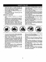
I. GENERAL OPERATION
• Read, understand, and follow all instructions on the machine and in the manual
before starting.
• Do not put hands or feet near rotating
parts or under the machine, Keep clear
of the discharge opening at all times.
o Only allow responsible adults, who are
familiar with the instructions, to operate
the machine.
• Clear the area of objects such as rocks,
toys, wire, etc., which could be picked
up and thrown by the blades.
• Be sure the area is clear of bystanders
before operating. Stop machineifanyone
enters the area.
• Never carry passengers.
• Do not mow in reverse unless absolutely
necessary. Always look down and behind
before and while backing.
•
Never direct discharged materialtoward
anyone. Avoid discharging material
against a wall or obstruction. Material
may ricochet back toward the operator.
Stop the blades when crossing gravel
surfaces.
• Do not operate machine without the entire grass catcher, discharge chute, or
othersafety devices inplace and working.
• Slow down before turning.
• Never leave a running machine unattended. Always turn off blades, set
parking brake, stop engine, and remove
keys before dismounting.
• Disengage blades when not mowing.
Shut off engine and wait for all parts to
come to a complete stop before cleaning
the machine, removingthe grass catcher,
or unclogging the discharge chute.
• Operate machine onlyin daylight or good
artificial light.
° Do not operate the machine while under
the influence of alcohol or drugs.
• Watch for traffic when operating near or
crossing roadways.
• Use extracarewhen loading or unloading
the machine into a trailer or truck.
o Always wear eye protection when operating machine.
- Data indicates that operators, age 60
years and above, are involved in a large
percentage of riding mower-related injuries. These operators should evaluate
their ability to operate the riding mower
safely enough to protectthemselves and
others from serious injury.
• Follow the manufacturer's recommendation for wheel weights or counterweights.
• Keep machine free of grass, leaves or
other debris build-up which can touch hot
exhaust/engine parts and burn. Do not
allow the mower to plow leaves or other
debris which can cause build-up to OCcur. Clean any oil or fuel spillage before
operating or storing the machine. Allow
machine to cool before storage.
II. SLOPE OPERATION
Slopes are a major factor related to loss of
control and tip-over accidents, which can
result in severe injury or death. Operation
on all slopes requires extra caution. If you
cannot back up the slope or ffyoufeel uneasy
on it, do not mow it.
° Mow up and down slopes, not across,
• Watch for holes, ruts, bumps, rocks, or
other hidden objects. Uneven terrain
could overturn the machine. Tall grass
can hide obstacles.
• Choose a low ground speed so that you
will not have to stop or shift while on the
slope.
• Do not mow on wet grass. Tires may lose
traction,
Always keep the machine in gear when
going down slopes. Do not shift to neutral
and coast downhill.
• Avoid starting, stopping, orturning on a
slope. Ifthetires]osetraction, disengage
the blades and proceed slowly straight
down the slope.
• Keep all movement on the slopes slow
and gradual.
Do not make sudden
changes in speed or direction, which
could cause the machine to roll over.
• Use extra care while operating machine
with grass catchers or other attachments;
they can affect the stability of the machine. Do no use on steep slopes.
• Do not try to stabilize the machine by
putting your foot on the ground.
• Do not mow near drop-offs, ditches,
or embankments. The machine could
suddenly roll over if a wheel is over the
edge or if the edge caves in,
•
Never carry children, even with the
blades shut off. They may fall off and
be seriously injured or interfere with safe
machine operation. Children who have
been given rides inthe past may suddenly
appear in the mowing area for another
ride and be run over or backed over by
the machine.
• Never allow children to operate the machine.
• Use extra care when approaching blind
corners, shrubs, trees, or other objects
that may block your view of a child.
IV. TOWING
• Tow only with a machine that has a hitch
desig ned for towing. Do not attach towed
equipment except at the hitch point.
- Fotlowthe manufacturer's recommendation for weight limits for towed equipmen t
and towing on slopes.
• Never allow children or others in or on
towed equipment.
• On slopes, the weight ofthetowed equipment may cause loss of traction and loss
of control.
• Travel slowly and allow extra distance to
stop,
V. SERVICE
SAFE HANDLING OF GASOLINE
To avoid personal injury or property damage, use extreme care in handling gasoline.
Gasoline is extremely flammable and the
vapors are explosive.
• Extinguish all cigarettes, cigars, pipes,
and other sources of ignition.
• Use only approved gasoline container.
• Never remove gas cap or add fuel with
the engine running. Allow engine to coot
before refueling.
• Never fuelthe machine indoors.
• Neverstorethemachineorfuelcontainer
where there is an open flame, spark, or
pilot light such as on a water heater or
other appliances.
• Never fill containers inside a vehicle or
on a truck or trailer bed with plasticliner.
Always place containers on the ground
away from your vehicle when filling.
• Remove gas-powered equipment from
the truck or trailer and refuel it on the
ground. Ifthis is not possible, then refuel
such equipmentwith a portable container,
rather than from a gasoline dispenser
nozzle.
I11.CHILDREN
Tragic accidents can occur if the operator
is not alert to the presence of children.
Children are often attracted to the machine
and the mowing activity. Never assume
that children will remain where you last
saw them.
•
Keep children out of the mowing area
and inthe watchful care of a responsible
adult other than the operator.
Be alert and turn machine off if a child
enters the area.
• Before and while backing, look behind
and down for small children,
4
°
•
°
Keep the nozzle in contact with the rim
of the fuel tank or container opening at
all times until fueling is complete. Do not
use a nozzle lock-open device.
lffuel is spilled on clothing, change clothing immediately.
Never overfill fuel tank, Replace gas cap
and tighten securely.
GENERAL SERVICE
°
•
•
•
Never operate machine in a closed
area.
Keep all nuts and boltstightto besurethe
equipment is in safe working condition.
Nevertamperwith safetydevices. Check
their proper operation regularly.
Keep machine free of grass, leaves, or
other debris build-up. Clean oi! or fuel
spillage and remove any fuel-soaked debris. Allow machineto cool before storing.
Do not mow in reverse unlessabsolutely
necessary, Always look down and behind
before and while backing,
Never carry children, even with the
blades shut off. They may fall off and
be seriously injuredor interferewith safe
machine operation. Children who have
been given rides inthe pastmaysuddenly
appear in the mowing area for another
ride and be run over or backed over by
themachine.
Keep children out of the mowing area
and in the watchful care of a responsible
adult other than the operator,
Be alert and turn machine off if a child
enters the area.
•
If you strike a foreign object, stop and
inspectthe machine. Repair, ifnecessary,
before restarting.
• Never make any adjustments or repairs
with the engine running.
• Check grass catcher components and the
discharge chute frequently and replace
with manufacturer's recommended parts,
when necessary.
o Mowerbfadesaresharp. Wraptheblade
or wear gloves, and use extra caution
when servicing them.
° Checkbrakeoperationfrequentty. Adjust
and service as required,
- Maintain or replace safety and instruction
labels, as necessary.
- Be sure the area is clear of bystanders
before operating. Stop machine if anyone
enters the area.
• Never carry passengers.
•
•
Before and while backing, look behind
and down for small children,
Mow up and down slopes (15° Max), not
across,
•
•
•
•
Choose a low ground speed so that you
will not have to stop or shift while on the
slope.
Avoid starting, stopping, or turning on a
slope. Ifthe tires Iosetraction, disengage
the blades and proceed slowly straight
down the slope.
if machine stops while going uphill,
disengageblades, shift intoreverse and
back down slowly,
Do notturn on slopes unless necessary,
and then, turn slowly and gradually
downhill, if possible.
PRODUCT
SPECIFICATIONS
Gasoline Capacity
and Type:
Oil Type
API-SG-SL):
Oil Capacity:
4 Gallons
UnleadedRegular
SAE 10W30(above32°Fj
SAE 5W30(below 32°1=)
W/Filter:
64 oz
Spark Plug:
Champion RCt2YC
(Gap: ,030")
Forward:
0 - 7.8
Reverse:
0 - 2.1
Ground Speed
REPAIR PROTECTION
AGREEMENTS
Congratulations on making a smart purchase.
Your new Craftsman4b product is designed
and manufactured for years of dependable
operation. But like all products, it may require
repair from time to time. That's when having
a Repair Protection Agreement can save you
money and aggravation.
Purchase a Repair Protection Agreement
now and protect yourself from unexpected
hassle and expense.
Here's what's included in the Agreement:
• Expertse_Jice byour 12,000 profesional
repair specialists.
ChargingSystem: 15 Amps @ 3600 RPM
Battery:
Amp/Hr:
28
Min. CCA: 230
Case size: UIR
Blade Bolt
45-55 Ft, Lbs.
Torque:
CONGRATULATIONS on your purchase of
a new tractor. It has been designed, engineered and manufactured to give you the best
possible dependability and performance,
Should you experience any problemyou cannot easily remedy, please contact a Sears or
other qualified service center. We have competent, well-trained representatives and the
proper tools to service or repair this tractor.
Please read and retain this manual. The
instructions will enable you to assemble
and maintain your tractor properly. Always
observe the "SAFETY RULES",
CUSTOMER RESPONSIBILITIES
• Read and observe the safety rules.
• Follow a regularschedule in maintaining,
caring for and using your tractor,
• Follow the instructions under "Maintenance" and "Storage" sections of this
owner's manual.
_WARNING:
This tractor is equipped with
an internal combustion engine andshould not
be used on or near any unimproved forestcovered, brush-covered or grass-covered
land unless the engine's exhaust system is
equipped with a spark arrestor meeting applicable local or state laws (ifany). if a spark
arrester is used, it should be maintained in
effective working order by the operator.
Inthe state ofCalifo rniathe above is required
by law (Section 4442 of the California Public
Resources Code). Other states may have
similar laws. Federal laws apply on federal
lands. A spark arrestor for the muffler is
availablethrough your nearest Sears service
center (See REPAIR PARTS manual),
•
Unlimited service and no charge for parts
and labor on all covered repairs.
•
Product replacement if your covered
product can't be fixed,
Discount of 10% from regular price of
service and service-related parts not
covered bythe agreement; also, 10% off
regular price of preventive maintenance
check,
-
•
Fast help by phone - phone support
from a Sears representative on products
requiring in-home repair, plus convenient
repair scheduling,
Once you purchase the Agreement, a
simple phone call is all that it takes for you
to schedule service. You can call anytime
day or night, or schedule a service appointment online.
Sears has over 12,000 professional repair
specialists, who have access to over 4.5
million quality parts and accessories, That's
the kind of professionalism you can count on
to help prolong the life of your new purchase
for years to come. Purchase your Repair
Protection Agreement today[
Some limitations and exclusions apply.
For prices and additional information call
1-800-827-6655.
SEARS INSTALLATION SERVICE
For Sears professional installation of home
appliances, garage door openers, water
heaters, and other major home items, inthe
U.S.A. call 1-800-4-MY-HOME®
6
Mower
©
Mower Front
(2) Rear
Lift Link
Assemblies
(5)
O.D.1-3/16
Washers
(1) Small
Retainer Springs
(1) Shoulder Bolt
(1) t-t/40.D.
Washer
(1) Front _-_
Lift Link
\_,_
(1) Wheel
Assembly
Retainer
Wheel
(1) 3/8-16
Locknut
Springs
i i HI
, I
(1) Oil Drain Tube
If Equipped
Keys
(1) Anti-Sway Bar
(1)
3/40.D.
Washers
(1) Small Retainer
Springs
It
(2) Keys
Slope Sheet
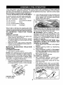
Your new tractor has been assembled at the factory with exception of those parts left
unassembled for shipping purposes. To ensure safe and proper operation of your tractor
all parts and hardware you assemble must be tightened securely. Use the correct tools
as necessary to ensure proper tightness.
TOOLS REQUIRED FOR ASSEMBLY
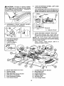
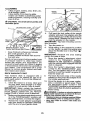
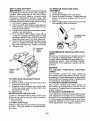
2. Lift up adjustmentlever (A)and slideseat
until a comfortable position is reached
A socket wrench set will make assembly
which allows you to press clutch/brake
easier. Standard wrench sizes are listed.
pedal all the way down.
(2) 7/16" wrenches
Utility knife
3. Release lever to lock seat in position.
(t) 1/2" wrench
Tire pressure gauge
(1) 3/4" wrench
Pliers
(I) 3/4" socket w/drive ratchet
(1) 9/16" wrench
Flashlight
When right or left hand is mentioned in this
manual, itmeanswhenyou areintheoperating
position (seated behind the steering wheel).
TO REMOVE
TRACTOR
FROM
CARTON
UNPACK CARTON
• Remove all accessible loose parts and
parts cartons from carton.
. Cut along dotted lines on al! four panels
of carton. Remove end panels and lay
side panels flat.
• Remove mower and packing materials.
• Check for any additional loose parts or
cartons and remove.
NOTE: You may now roll yourtractor off the
skid. Followthe appropriate instruction below
to remove the tractor from the skid.
_:_ WARNING: Before starting, read, understand and follow all instructions in the
Operation section of this manual. Be sure
tractor is in a well-ventilated area. Be sure
the area in front of tractor is clear of other
people and objects.
TO ROLL TRACTOR OFF SKID (See
Operation
section for location
and
function of controls)
1. Raise attachment lift lever to its highest
position.
2. Release parking brake by depressing
brake pedal.
3. Place freewheel control in disengaged
position to disengage transmission (See
'q'O TRANSPORT" inthe Operation section of this manual).
4. Roll tractor forward off skid.
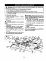
TO INSTALL MOWER
1. SET PARKING BRAKE LEVER AND
LOWER ATTACHMENT LIFT LEVER
• Depress clutch!brake pedal all the way
down and hold.
• Pull parking brake lever up and hold,
release pressure from clutch/brake pedal,
then release parking brake lever. Pedal
should remain in brake position. Ensure
parking brake will hold tractor secure.
BEFORE
REMOVING
TRACTOR
FROM SKID
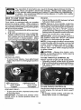
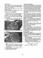
TO CHECK BATTERY
I. Lift hood to raised position,
NOTE: If this battery is put into service after
month and year indicated on label (label is
located between terminals) charge battery
for minimum of one hour at 6-10 amps. (See
"BATTERY" in Maintenance section of this
manual for charging instructions),
. Forbatteryand batterycableinstallationsee
"REPLACING BATTERY"inthe"Service
and Adjustments" section in this manual.
Label
ADJUST SEAT
1. Sit in seat.
8
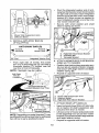
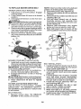
3. TURN STEERING WHEEL LEFT AND
POSITION MOWER
• Turn steering wheel to the left as far as it
will go and position moweron rightside of
tractorwith deflectorshie[d (Q)to the right,
,_CAUTION: Lift lever is spring loaded.
Have a tight grip on lift lever, lower it slowly
and engage in lowest position, Lift lever is
[ocated on left side of fender.
Uft
Lever
Front
2. ASSEMBLE FRONT GAUGE WHEEL
e_V)TO FRONT OF MOWER
Q,
Deflector
Shield
4. SLIDE MOWER UNDER TRACTOR
•
H.
W.
X,
Y
Z.
Front Mower Bracket
Front Gauge Wheel
Shoulder Bolt
1-1/40.D. Washer
3/8-t6 Locknut
Bring belt forward and check belt for
properrouting in all mowerpuIley grooves.
NOTE: Be sure mower side suspension
arms (A) are pointing forward before sliding
mower under tractor.
• Slide mower under tractor until it is
centered under tractor,
A,
B.
C.
D.
E.
E
H.
Mower Side Suspension Arms
Retainer Spring
Rear Lift Unk(S)
Right Side Rear Mower Bracket
Front Lift Unk Assembly
Front Suspension Bracket
Front Mower Bracket
I.
K,
L
M,
Q.
S.
W,
9
Left Side Rear Mower Bracket
Belt Tension Rod
Locking Bracket
Engine Clutch Pulley
Deflector Shield
Anti-Sway Bar
Front Gauge Wheel
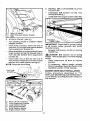
•
•
Pivot the integrated washer end of antisway bar (S)towards mower deck bracket
on right side of mower. Insert integrated
washer end of bar into hole in rear mower
bracket (D). Move mower as needed to
insert integrated washer end of bar into
rear mower bracket (D).
Secure with small washer and small
retainer spring as shown.
A. Mower Side SuspensionArms
Q. Deflector Shield
5, INSTALL ANTI-SWAY BAR (S)
(IF EQUIPPED)
_
ANTI-SWAY
Towards
Transaxle
90° End
BAR (S)
Towards
Mower Deck
D. Right Side Rear MowerBracket
S. Anti-SwayBar
T. TransaxleBracket
IntegratedWasherEnd
6. ATTACH MOWER SIDE SUSPENSION
ARMS (A) TO CHASSIS
• Position front hole inside suspension arm
(A) over pin on outside of tractor chassis
and secure with large washer and large
retainer spring (B).
° Repeat on opposite side of tractor.
t
From right side of mower, first insert
90 ° end of anti-sway bar (S) into hole in
transaxle bracket (T), located near left
rear tire in front of transaxle,
NOTE: Flashlight may be helpful.
Anti-Sway
Bar (S)
Location.,,_
I_
z? ..............
,:.Ci
/
_'._z%> _ [ J
' i......."-.
"-,
\
Transaxle Bracket (_
Located Between Rear Tires
A, Mower Side Suspension Arms
B, Retainer Spring
D, Right Side Rear Mower Bracket
7. ATTACH REAR LIFT LINKS (C)
• Insert rod end of rear lift link (C) into hole
(U) in tractor lift shaft suspension arm
and pivot link down to mower,
• Lift rear corner of mower and position slot
in link assembly over pin on rear mower
bracket (D) and secure with large washer
and large retainer spring.
• Repeat on opposite side of tractor.
NOTE: Depending on model, bracket (T)may
be different than shown but hole for anti-sway
bar will be in same position/location.
10
9 INSTALL BELT ON ENGINE CLUTCH
PULLEY (M)
• Disengage belt tension rod (K) from
locking bracket (L).
• Install belt onto engine clutch pulley (M).
D.
'U.
Mower Bracket
Hole
8 ATTACH FRONT LINK (E)
• Turn steering wheel to position wheels
straight forward.
• From front of tractor, insert rod end of
front link (E) through front hole in tractor
front suspension bracket (F),
• Move to leftside of mower and and insert
large retainer spring (G) through hole in
front link (E) behind front suspension
bracket (F).
• Insert other end of link (E) into hole in
front mower bracket (H) and secure with
washer and small retainer spring (J).
NOTE: Requires deck lifting.
Front Link
Location,
[
!
M.Engine
Clutch Pulley
IMPORTANT: Check belt for properrouting
in all mower pufley grooves and under
mandrel covers.
•
_CAUTION:
Belt tension rod is spring
loaded. Have atight grip on rod and engage
slowly.
• Raise attachment lift lever to highest
position.
• If necessary, adjust gauge wheels
before operating mower as shown in the
Operation section of this manual,
I
/"
Engage belt tension rod (K) on locking
bracket (L),
MOWER DRWE BELT INSTALLATION
Follow procedure
described
in "TO
REPLACE MOWER BLADE DRIVE BELT"
in the "Service and Adjustments" section of
this manual.
- -'\
_J
-_'. Front Lift Link Assembly
E Front Suspension Bracket
G. Large Retainer Spring
H. Front Mower Bracket
J. Small Retainer Spring
M. Engine Clutch Pulley
11
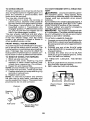
CHECK TIRE PRESSURE
The tires on your tractor were over-inflated
atthe factory for shipping purposes. Correct
tire pressure is important for best cutting
performance.
• Reducetire pressure to PSf shown ontires,
CHECK DECK LEVELNESS
For best cutting results, mower housing
should be properly leveled. See "TO LEVEL
MOWER" in the Service and Adjustments
section of this manual.
CHECK FOR PROPER POSITION OF
ALL BELTS
See the figures that are shown for replacing
motion and mower blade drive belts in the
Service and Adjustments section ofthis manual, Vedfy that the belts are routed correctly.
CHECK BRAKE SYSTEM
After you learn how to operate your tractor,
checkto see that the brake isoperating properly. See"TO CHECKBRAKE" intheService
and Adjustments section of this manual.
t/If'CHECKLIST
Before you operate your new tractor,we
wish to assure that you receive the best
performance and satisfaction from this
Quality Product,
Please review the following checklist:
t/" All assembly instructions have been
completed.
J" No remaining loose parts in carton.
_" Battery is properly prepared and
charged.
vf Seat is adjusted comfortably and tightened securely.
J" All tires are properly inflated, (For shipping purposes, thetires were overinflated
at the factory).
i/" Be sure mower deck is properly leveled
side-to-side/front-to-rear for best cutting
results. (Tires must be properly inflated
for leveling).
J" Check mower and drive belts. Be sure
they are routed properly around pulleys
and inside all belt keepers.
_4" Check wiring. See that all connections
are still secure and wires are properly
clamped,
_" Before driving tractor, be sure freewheel
control is in "transmission engaged"
position (see "TO TRANSPORT" in the
Operation section of this manual).
While learning howto useyour tractor, pay extra attention to the following important items:
V" Engine oil is at proper level,
v( Fuel tank is filled with fresh, clean, regular
unleaded gasoline.
v( Become familiar with all controls, their
location and function. Operate them
before you start the engine.
_/" Be sure brake system is insafe operating
condition.
_/" Be sure Operator Presence System and
Reverse Operation System (ROS) are
working properly (See the Operation and
Maintenance sections in this manual).
_" It is important to purge the transmission
before operating your tractor for the first
time. Follow proper starting and transmission purging instructions (See "TO START
ENGIHE" and "PURGETRANSMISSION"
inthe Operation section of this manual).
12
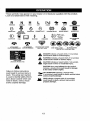
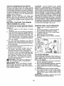
These
symbols
mayappear
onyourtractor
or inliterature supplied
with the product.
Learn and understand their meaning.
R
N
REVERSE
ENGINE
OFF
L
H
NEUTRAL
REVERSE
OPERATION
SYSTEM
(ROS)
HIGH
ENGINE
I'-.I
LOW
ON
ENGINE
CHOKE
START
FAST
PARKING
BRAKE
SLOW
MOWER
IGNmON
SWITCH
MOWER
HEIGHT
LIFT
÷
LIGHTS
ON
FUEL
BATTERY
REVERSE
FORWARD
CRUISE
CONTROL
CLUTCH/BRAKE
PEDAL
®@@@@
ATTACHMENT
CLUTCH DISENGAGED
ATTACHMENT
CLUTCH
ENGAGED
DANGER,
KEEP HANDS
AND FEET AWAY
KEEP AREA
CLEAR
(SEE SAFETY
SLOPE
RULES
HAZARDS
SEC'i'ION)
DANGER
which,
if not avoided,
will
result indicates
in death aorhazard
serious
injury.
WARNING
hazard
which,
if not avoided,
could
resultindicates
in deatha or
serious
injury.
FREEWHEEL
(Automatic Models only)
CAUTION
indicates
a hazard
which, if
not avoided,
might result
in minor
or moderate
injury.
CAUTION when used without the alert symbol,
indicates a situation that could result tn damage
to the tractor and/or engtne.
Failure to follow instructions
could result in serious injury or
death. The safety alert symbol
is used to identify safety information about hazards which can
result in death, serious injury
and/or property damage,
HOT SURFACES indicates a hazard which,
if not avoided, could result in death, serious
and/or property damage.
/_
FIRE indicates
hazard serious
which, ifinjury
not avoided,
could
result in adeath,
and/or
property damage,
13
injury
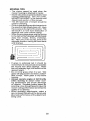
KNOW YOUR TRACTOR
READ THIS OWNER'S MANUAL AND SAFETY RULES BEFORE OPERATING YOUR
TRACTOR
Compare the illustrations with your tractor to familiarize yourself with the locations of
various controls and adjustments. Save this manual for future reference.
Our tractors conform to the applicable safety standards of the
American National Standards Institute.
(A) ATTACHMENT LIFT LEVER- Used to
raise and lower the mower or other attachments mounted to your tractor.
(B) BRAKE PEDAL - Used for brakingthe
tractor and startingthe engine.
(C) PARKING BRAKE- Locks clutch/brake
pedal into the brake position.
(D) THROTTLE CONTROL- Used to control engine speed.
(E) ATTACHMENT CLUTCH SWITCH
- Used to engage the mower blades, or other
attachments mounted to your tractor.
(F) IGNITION SWITCH - Used for starting
and stopping the engine.
(G) REVERSE OPERATION SYSTEM
(ROS) "ON" POSITION- Allows operation
of mower or other powered attachment while
in reverse.
(H) LIGHT SWITCH - Turnsthe headlights
on and off.
(J) CRUISE CONTROL LEVER- Used to set
forward movement oftractor atdesired speed
without holding the forward drive pedal,
(K) FORWARD DRIVE PEDAL - Used for
forward movementof tractor.
(L) REVERSE DRIVE PEDAL- Usedforreverse
movementof tractor.
(N) CHOKE CONTROL- Used when starting
a cold engine.
(P) SERVICE REMINDER / HOUR METER
- Indicates when service is required for the
engine and mower.
14
Theoperation
ofanytractor
canresult
inforeign
objects
thrown
intothe
eyes,which
canresult
insevere
eyedamage.
Always
wearsafety
glasses
oreyeshields
whileoperating
yourtractor
orperforming
anyadjustments
orrepairs.
Werecommend
standard
safety
glasses
orawidevision
safety
maskworn
overspectacles.
HOW TO USE YOUR TRACTOR
TO SET PARKING BRAKE
Your tractor is equipped with an operator
presence sensing switch. When engine is
running,any attempt bythe operatortoleave
theseat withoutfirstsetting the parkingbrake
will shut offthe engine.
t. Depress brake pedat(B) allthe waydown
and hold.
2. Pull parking brake lever (C) up and hold,
release pressure from brake pedal (B),
then release parking brake lever. Pedal
should remain in brake position. Make
sure parking brake will holdtractorsecure.
ENGINE • Movethrottle control (D) between half and
full speed (fast) position.
NOTE: Failure to move throttle control between half and full speed (fast) position, beforestopping, may cause engineto"backfire".
* Turn ignition key (F) to "STOP" position
and remove key. Always remove keywhen
leaving tractor to prevent unauthorized use.
° Never use choke (N) to stop engine.
IMPORTANT: Leavingthe ignitionswitch in
any position other than "STOP" will cause
the battery to discharge and go dead.
NOTE: Undercertain conditionswhentractor
is standing idle with the engine running, hot
engine exhaust gases may cause "browning" of grass. To eliminate this possibility,
always stop engine when stopping tractor
on grass areas.
ACAUTION:
Always stop tractor completely, as described above, before leaving
the operator's position.
STOPPING
MOWER BLADES - TOstop mower blades, move attachment
clutch clutch lever to disengaged position
(t'_1) Attachment
ClutchSwitch
"Engaged....
TO USE THROTTLE CONTROL (D)
Always operate engine at full speed (fast).
° Operating engine at less than full speed
(fast)reduces engine's operatingefficiency.
• Full speed (fast) offers the best mower
performance.
(t'_)Attachment
ClutchSwitch
Disengaged"
TO USE CHOKE CONTROL (N)
Use choke controlwheneveryou arestarting
a cold engine. Do not use to start a warm
engine.
• To engage choke control, pull knob out.
Slowly push knob in to disengage.
GROUND DRIVE • Tostop ground drive, depress brake pedal
all the way down.
IMPORTANT: Forward and reverse drive
pedals return to neutral position when not
depressed.
15
TO MOVE FORWARD AND BACKWARD
The direction and speed of movement is
controlled by the forward and reverse drive
pedals.
1. Start tractor and release parking
brake.
2, Slowly depress forward(K) or reverse(L)
drive pedal to begin movement. Ground
speed increases the further down the
pedal is depressed.
TO USE CRUISE CONTROL
The cruise control feature can be used for
forward travel only.
SYSTEM CHARACTERISTICS
The cruise control should only be used
while mowing or transporting on relatively
smooth, straight surfaces. Other conditions
such as trimming at slow speeds may cause
the cruise control to disengage. Do not use
the cruise control on slopes, rough terrian
or while trimmimg or turning.
- With forward drive pedal depressed to
desired speed, pull cruise control lever
(J) up and hold while lifting your foot off
the pedal, then release the lever.
To disengage the cruise control, depress the
brake pedal, tap on forward drive pedal or
push the cruise control lever down.
TO ADJUST MOWER CUTTING HEIGHT
The position of the attachment lift lever (A)
determines the cutting height.
• Put attachment lift lever indesired cutting
height slot.
• Slide pointer tab (T) to desired cutting
height as a reminderfor nexttimeyou mow,
The cutting height range is approximately
1"to 4". The heights are measured from the
groundtothe bladetipwith the engine not running. These heights areapproximateand may
vary depending upon soil conditions, height
of grass and types of grass being mowed.
• The average lawn should be cut to approximately 2-1/2" during the cool season
and to over 3" during hot months. For
healthier and better looking lawns, mow
often and after moderate growth.
• For best cutting performance, grass over
6" in height should be mowed twice. Make
the first cut relatively high; the second to
desired height.
TO ADJUST GAUGE WHEELS
Gauge wheels are properly adjusted when
they are slightly off the ground when mower
is at the desired cutting height in operating
position.Gauge wheels then keep the deck
in proper position to help prevent scalping
in most terrain conditions.
NOTE: Adjust gauge wheels with tractor on
a flat level surface.
1. Adjust mower to desired cutting height
(See 'q'O ADJUST MOWER CUTTING
HEIGHT" in this section of manual)i
2. With mowerin desired heightofcutposition, gauge wheels should be assembled
so they are slightly off the ground, Install
gauge wheel in appropriate hole. Tighten
securely.
3. Repeat for all, installing gauge wheel in
same adjustment hole.
TO OPERATE MOWER
Your tractor is equipped with an operator
presence sensing switch, Any attempt bythe
operator to leave the seat with the engine
running and the attachment clutch engaged
will shut off the engine. You must remain
fully and centrally positioned in the seat to
preventthe engine from hesitating or cutting
offwhen operating your equipmenton rough,
rolling terrain or hills,
1. Select desired height of cut with attachment lift lever.
2. Start mower blades by engaging attachmerit clutch control.
16
TO STOP MOWER BLADES
Disengage attachment clutch control.
_OAUTION:
Do not operate the mower
without either the entire grass catcher, on
mowers so equipped, orthe deflector shield
(S) in place.
REVERSE OPERATION SYSTEM (ROS)
Your tractor is equipped with a Reverse
Operation System (ROS). Any attempt by
the operatorto travel inthe reversedirection
withthe attachmentclutch engaged willshut
off the engine unless ignitionkey is placed
in the ROS "ON" position.
_WARNING:
Backing up with the attachment clutch engaged while mowing is
stronglydiscouraged. Turning the ROS"ON",
to allow reverse operation with the attachment clutch engaged, should only be done
when the operator decides it is necessary to
reposition the machine with the attachment
engaged. Do not mow in reverse unless
absolutely necessary.
USINGTHE REVERSEOPERATIONSYSTEM
Only use if you are certainno childrenorother
bystanders will enter the mowing area.
1. Depress brake pedal all the way down.
2. With engine running, turn ignition key
counterclockwiseto ROS "ON" position.
3. Look down and behind before and while
backing.
4, Slowly depress reverse drive pedal to
start movement.
5. When use of the ROS is no longer
needed, turn the ignition key clockwise
to engine "ON" position.
ROS "ON" Position
Engine "ON" Position
(Normal Operating)
17
TO OPERATE ON HILLS
_)AWARNING: Do not drive up or down
hills withslopes greater than 15° and do not
drive across any slope. Use the slope guide
provided at the back of this manual.
• Choose the slowest speed before starting
up or down hills.
• Avoid stopping or changing speed on
hills.
• If stopping is absolutely necessary, push
brake pedal quickly to brake position and
engage parking brake.
• Torestart movement, slowly release parking brake and brake pedal.
• Slowly depress appropriate drive pedal to
slowest setting.
• Make all turns slowly.
TO TRANSPORT
When pushing or towing your tractor, be
sure to disengage transmission by placing
freewheel control in freewheeling position.
Free wheel control is located at the rear
drawbar of tractor.
• Raise attachment lift to highest position
with attachment lift control.
• Pull freewheel controI out and into the slot
and release so it is held inthe disengaged
position.
• Do not push or tow tractor at more than
two (2) MPH.
° Toreengagetransmission, reverseabove
procedure.
NOTE: To protect hood from damage when
transportingyour tractoron atruck or atrailer,
be sure hood is closed and secured to tractor.
Use an appropriate means of tying hood to
tractor (rope, cord, etc.).
TOWING CARTS AND OTHER ATTACHMENTS
Tow only the attachments that are recommended by and comply with specifications
of the manufacturer of your tractor. Use
common sense when towing. Too heavy of
a load, while on a slope, is dangerous. Tires
can lose traction with the ground and cause
you to lose control of your tractor.
SERVICE REMINDER/HOUR METER
Service reminder shows the total number
of hours the engine has run and flashes to
indicate that the engine or mower needs servicing. When service is required, the service
reminder will flash for two hours. To service
engine and mower, see the Maintenance
section of this manual.
NOTE: Service reminder runs when the
ignition key is in any position but "STOP".
For acurate reading, be sure key remains
in the "STOP" position when engine is not
running.
BEFORE STARTING THE ENGINE
CHECK ENGINE OIL LEVEL
The engine inyour tractor has been shipped,
from the factory, already filled with summer
weight oil.
1. Check engine oil with tractor on level
ground.
2. Unthread and remove oilfill cap/dipstick;
wipe oil off. Reinsert the dipstick into the
tube and rest oil fill cap on the tube. Do
notthreadthe capontothetube. Remove
and read oil level. If necessary, add oil
until "FULE' mark on dipstick is reached.
Do not overfill.
3. For cold weather operation you should
change oil for easier starting (See the oil
viscosity chart in the Maintenance section
of this manual).
4. Tochange engine oil, seethe Maintenance
section in this manual.
5. Fill fuel tank to bottom of filler neck. Do
not overfill. Use fresh, clean, regular
unleaded gasoline with a minimum of
87 octane. (Use of leaded gasoline will
increase carbon and lead oxide deposits
and reduce valve life). Do not mix oil
with gasoline. Purchase fuel in quantities that can be used within 30 days to
_assure fuel freshness.
_IbCAUTION: Wipe off any spilled oil or
t'uel. Do not store, spill or use gasoline
near an open flame.
IMPORTANT: When operating in temperatures below 32°F(0°C), use fresh, clean
winter grade gasoline to help ensure good
cold weather starting.
18
CAUTION: Alcohol blended fuels (called
gasohol or using ethanol or methanol) can
attract moisture which leads to separation
and formation of acids during storage. Acidic
gas can damagethe fuel system of an engine
while in storage. Toavoid engine problems,
the fuel system should be emptied before
storage of 30 days or longer. Drain the gas
tank, start the engine and let it run until the
fuel lines and carburetor areempty. Usefresh
fuel next season. See Storage Instructions
for additionaI information. Never use engine
or carburetor cleaner products in the fueltank
or permanent damage may occur.
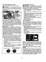
RESERVE FUEL VALVE OPERATION
1. Raise seat to access reserve fuel
valve.
2. in normal operation,valve should be
set to primary (as shown in view)
3, If tractorruns out of fuel, rotate valve
handle to reserve.
4, Drive tractor to be refueled.
5. After refueling, return valve to primary
position.
Reserve
Fuel Valve
©
Primary
TO START ENGINE
When starting the engine for the first time or
if the engine has run out of fuel, it will take
extra cranking time to move fuel from the
tank to the engine,
1. Be sure freewheel control is inthe transmission engaged position.
2. Siton seat inoperating position, depress
brake pedal and set parking brake.
3. Move attachment clutch to disengaged
position.
4. Move throttle control to fast position
5. Pull choke control out for a cold engine
start attempt. For a warm engine start
attempt the choke control may not be
needed.
NOTE: Before starting, read the warm and
cold starting procedures below.
6. Insert key into ignition and turn key
clockwise to start position and release
key as soon as engine starts. Do not run
starter continuously for more than fifteen
seconds per minute. If the engine does
not start after several attempts, push
choke control in, wait afew minutes and
try again. If engine still does not start, pull
the choke control out and retry.
WARM WEATHER STARTING (50°F/10°C
and above)
7. When engine starts, slowly push choke
control in until the engine begins to run
smoothly. If the engine start_ to run
roughly, pull the choke control outslightly
for a few seconds and then continue to
push the control in slowly.
8. The attachments and ground drive can
now be used. If the engine does not accept
the load, restart the engine and allow it to
warm up for one minute using the choke
as described above.
COLD WEATHER STARTING (50_F/10°C
and below)
9. When engine starts, slowly push choke
Control in until the engine begins to run
smoothly. Continue to push the choke
control insmall steps allowing the engine
to accept small changes in speed and
load, until the choke control is fully in.
If the engine starts to run roughly, pull
the choke control out slightly for a few
seconds and then continue to push the
control in slowly. This may require an
engine warm-up period from several
seconds to several minutes, depending
on the temperature.
AUTOMATIC TRANSMISSION WARM UP
Before driving the unit in cold weather, the
transmissionshould bewarmed upas follows:
I. Be sure the tractor is on level ground.
2. Release the parking brake and let the
brake slowly return to operating position.
3. A![ow one minute for transmission to
warm up. This can be done during the
engine warm up period.
4. The attachments can be used during the
enginewarm-up period after thetransmission has been warmed up and may require
the choke control be pulled out slightly.
NOTE: If at a high altitude (above 3000 feet)
or in cold temperatures (below 32°F/0°C)
the carburetor fuet mixture may need to De
adjusted for best engine performance (see
"TO ADJUSTCARBURETOR"intheService
and Adjustments section of this manual).
19
PURGE TRANSMISSION
,_CAUTION:
Never engage or disengage
freewheel lever while the engine is running.
Toensure properoperationand performance,
it is recommended that the transmissionbe
purged before operating tractor for the first
time. This procedurewill removeanytrapped
air inside the transmission which may have
developed during shipping of your tractor.
IMPORTANT: Should your transmission
require removal for service or replacement,
itshoutd be purged after reinstaUation before
operating the tractor.
1, Place tractor safely on a level surfacethat is clear of objects and open - with
engine off and parking brake set.
2. Disengage transmission
by placing
freewheel control in disengaged position
(See "TO TRANSPORT" in this section
of manual).
3. Sitting in the tractor seat, start engine.
After the engine is running, move throttle
control to slow position. Disengage parking brake.
,_IbCAUTiON: At any time, during step 4,
there may be movement of the drive wheels.
4. Depress forward drive pedalto full forward
position and hold forfive (5) seconds and
release pedal. Depress reverse drive
pedal to full reverse position and hold
for five (5) seconds and release pedal.
Repeat this procedure three (3) times.
5. Shutoff engine and set parking brake.
6. Engage transmission by placing freewheel control in engaged position (See
"TO TRANSPORT" in this section of
manual).
7. Sitting in the tractor seat, start engine.
After the engine isrunning, move throttle
control to half (1/2) speed. Disengage
parking brake.
8. Drive tractor forward for approximately
five feet then backwards for five feet,
Repeat this driving procedure three
times.
Your transmission is now purged and now
ready for normal operation,
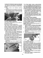
MOWING TIPS
° Tire chains cannot be used when the
mower housing is attached to tractor,
° Mower should be proper[yleveled for best
mowing performance. See "TO LEVEL
MOWER HOUSING" in the Service and
Adjustments section of this manual,
- The ]eft hand side of mower should be
used for trimming.
• Drive so that clippings are discharged onto
the areathat has already been cut, Have
the cut area to the right of the tractor, This
will result in a more even distribution of
clippings and more uniform cutting.
• When mowing large areas, start by turning
to the right so that c]ippings will discharge
away from shrubs, fences, driveways,
etc. After one or two rounds, mow in the
opposite direction making ]efthand turns
• If grass is extremely tall, it should be
mowed twice to reduce load and possible
fire hazard from dried clippings, Make
first cut relatively high; the second to the
desired height.
• Do not mow grass when it is wet. Wet
grass will plug mower and leave undesirable clumps. Allow grass to dry before
mowing.
• Always operate engine at full throttle
when mowing to assure better mowing performance and proper discharge
of material. Regulate ground speed by
selecting a lowenough speed to give the
mower cutting performance as well as the
quality of cut desired.
• When operating attachments, select a
ground speed that wilt suit the terrain and
give best performance of the attachment
being used.
2O
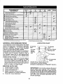
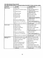
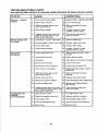
MAINTENANCE
SCHEDULE
II
Check
Brake
BEFORE
F-A_H
USE
iiiiiiii
EVERY
e
HOURB
EVeRy
25
HOURS
EVERY
50
HOURS
,
EVERY
1130
IIOURS
EVERY
SEASON
,,,,
BEFORE
STORAGE
i
Oeeratfon
V'
RT CheekTire
Cheek Operator
Pressure
Presence
i
Check
far Loose
C
Check/Replace
T
Lubr!cation
0
Check
Battery
R
Clean
Battery
Clean
Debds
,,
.....
,
....
Fasteners
Mower
V',,,
Vp
& ROS Systems
....
Blades
v'
,,
,!
.....
Chart
v"
.....
Level
v'=
V*4 .........
and Tsrminals
Off Stee[,ing
_'
' '
v't
Plate
Check Transaxle Cooling
v'
Check Mower LeveInes F
Check V-8 elts
Check
ER,qine
Change
Oil
EnF!ine
E
Change
Engine
N
Clean
Air Filter
G
,Ct,ean
Air
Level
OEI {with
Oi
............
oil filter)
_wthouto
fter)
,,
_
V',_
v"
......
v',
Screen
v"
| i Inspect MuffIerlSpark An-ester
N
....v',._
Replace Oil Filter (If equ{pped}
Clean
En_t!ne
CooliNg
Fins
,Replace Spark Plug
Replace
! Replace
Air Filter
Fuel
Paper,Cartridge
Filter
......
H ,1
GENERAL RECOMMENDATIONS
LUBRICATION CHART
The warrantyon this tractordoes not cover
items that have been subjected to operator
Spindle .---_]__,
f---_qL'-_(_ Spindle
abuse or negligence, To receive full value Z@e
from the warranty, operator must maintain
rK
.__==:_-_L
Zerk
.
tractor as instructed in this manual.
@ Front _
.......... _'i iX@ FrontWheel
Some adjustments will need to be made peBearing
,._.=...... _,>_
riodically to properlymaintain your tractor.
zerk
/'_ / _"_ ]i _'-._',.
At least once a season, check to see if
you should make any of the adjustments
described in the Service and Adjustments
(. > ,,__2
,/':..
. @,Engine
section of this manual.
I I
I 1
- At least once a year you should replace
II
: (_Gearshiffl
the spark plug, clean or replace air filter,
and check blades and belts for wear. A
L "_£°'_-- = Pivots
new spark plug and clean air filter assure d)SAE 30 or 10w30 Motor Oil
proper air-fuel mixture and help your en- ® General Purpose Grease
gine run better and last longer,
@Refer to Maintenance "ENGINE" Section
BEFORE EACH USE
1. Check engine oil level.
IMPORTANT: Do not oil or grease the pivot
2. Check brake operation.
points which have special nylon bearings.
3. Check tire pressure.
Viscous lubricants wil! attract dust and dirt
4. Check operatorpresence and
thatwitl shorten the life of the self-lubricating
ROS systems for proper operation.
bearings. Ifyou feel they must be lubricated,
5. Check for loose fasteners.
use only a dry, powdered graphite type lubricant sparingly.
21
TRACTOR
Always observe safety ruleswhen performing
any maintenance.
BRAKE OPERATION
If tractor requires more than five (5) feet to
stop at highest speed in highest gear on a
level, dry concrete or paved surface, then
brake must be serviced. (See "TO CHECK
BRAKE" in the Service and Adjustments
section of this manual).
TIRES
- Maintain proper air pressure in all tires
(See PSI on tires).
• Keep tires free of gasoline, oil, or insect
control chemicals which can harm rubber.
• Avoid stumps, stones, deep ruts, sharp
objects and other hazards that may cause
tire damage,
NOTE: To seal tire punctures and prevent
flat tires due to slow leaks, tire sealant may
be purchased from your local parts dealer.
Tire sealant also prevents tire dry rot and
corrosion.
OPERATOR PRESENCE SYSTEM AND
REVERSE OPERATION SYSTEM (ROS)
Be sure operator presence and reverse
operation systems are working properly, if
your tractor does not function as described,
repair the problem immediately.
• The engine should not start unless the
brake pedal is fully depressed, and the
attachment clutch control is in the disengaged position.
CHECK
OPERATOR
PRESENCE
SYSTEM
• When the engine is running, any attempt
by the operator to leave the seat without
first setting the parking brake should shut
off the engine.
• When the engine is running and the attachment clutch is engaged, any attempt
by the operator to leave the seat should
shut off the engine.
• The attachment clutch should never operate unless the operaLor is in the seat.
ROS "ON" Position
Engine "ON" Position
(Normal Operating)
22
CHECK REVERSE OPERATION (ROS)
SYSTEM
• When the engine is running with the ignition
switch inthe engine "ON" position and the
attachment clutch engaged, any attempt
by the operator to shift into reverse should
shut off the engine.
• When theengine is runningwith theignition
switch in the ROS "ON" position and the
attachment clutch engaged, any attempt
bythe operator to shift into reverse should
NOT shut off the engine.
BLADE CARE
For best results mower blades must besharp.
Replace worn, bent or damaged blades.
ACAUTION: Use only a replacement blade
approved bythe manufacturer of your tractor,
Using a blade not approved by the manufacturer of your tractor is hazardous, could
damage your tractor and void your warranty.
BLADE REMOVAL
1. Raise mower to highestpositionto allow
access to blades,
NOTE: Protectyour handswith glovesand/
or wrap blade with heavy cloth.
2. Remove blade bolt by turning counterclockwise.
3. installnewbladewithstamped"THIS SIDE
UP" facing deck and mandrel assembly.
IMPORTANT: To ensure proper assembly,
center hole in blade must align with star on
mandrel assembly.
4. Install and tighten blade bolt securely
(45-55 Ft. Lbs. torque).
IMPORTANT: Special blade bolt is heat
treated,
Mandrel
Assembly
Blade
BATTERY
_
.-_
Center Hole--"4_&
Your tractor has a battery charging system
which is sufficient for normal use. However,
periodic charging of the battery with an automotive charger wilt extend its life.
• Keep battery and terminals cIean.
• Keep battery bolts tight.
• Keep small vent holes open.
• Recharge at 6-10 amperes for 1 hour.
NOTE: The original equipment battery on
your tractor is maintenance free. Do not
attempt to open or remove caps or covers.
Adding or checking level of electrotyte is
not necessary.
TOCLEAN
BATFERY
ANDTERMINALSChange the oil after every 50 hours of opCorrosion
anddirtonthebattery
andtermi- eration or at least once a year if the tractor
not used for 50 hours in one year.
nalscancause
thebattery
to"leak"
power. isCheck
the crankcase oil level before start1. Remove
terminal
guard.
2. Disconnect
BLACK
battery
cablefirst ing the engine and after each eight (8)
thenREDbatterycableandremovehours of operation,
battery
fromtractor.
TO CHANGE ENGINE OIL
3. Rinsethe
batterywith
plain
waterand
dry. Determine temperature range expected
4. Clean
terminals
andbattery
cableends before oil change. All oil must meet API
withwirebrush
untilbright.
classification SG-SL.
5. Coat
terminals
withgrease
orpetroleumservice
• Be sure tractor is on level surface,
jelly,
, Oil will drain more freely when warm.
6. Reinstall
battery(See"REPLACING
oil in a suitable container,
BATTERY"
intheSERVICE
ANDAD- •1. Catch
Remove oil fill cap/dipstick, Be careful
JUSTMENTS
section
ofthismanual), not to allow dirt to enter the engine when
TRANSAXLE MAINTENANCE
The transmission fan and cooling fins should
be kept clean to assure proper cooling. Do
not attempt to clean fan or transmission while
engine is running or while the transmission
is hot. To prevent possible damage to seals,
do not use high pressure water or steam to
clean transaxte.
• Inspect cooling fan to be sure fan blades
are intact and clean,
• Jnspect cooling fins for dirt, grass clippings
and other materials. Topreventdamageto
sea_s, do not use compressed air or high
pressure sprayer to clean cooling fins.
TRANSAXLE PUMP FLUID
The transaxle was sealed at the factory and
fluid maintenance is not required for the life
of the transaxle. Should thetransaxle ever
leak or require servicing, contact your nearest Sears or other qualified service center.
V-BELTS
CheckV-belts for deterioration andwear after
t 00 hours of operation and replace ff necessary. The belts are not adjustable. Replace
belts if they begin to slip from wear.
ENGINE
LUBRICATION
Only use high quality detergent oil rated
with API service classification SG-SL.
Select the oil's SAE viscosity grade
according to your expected operating
temperature.
changing oil.
2. Remove yellow cap from end of drain
valve and install the drain tube onto the
fitting.
3. Unlock drain valve by pushing inward
slightly and turning counterclockwise.
Oil Drain Valve
Closed
___
" __._ra_
YellowCap1"__
4. To open, pull out on the drain valve.
5. After oil has drained completely, close and
lock the drain valve by pushing inward
and turning clockwise until the pinis in
the locked position as shown.
6, Remove the drain tube and replace the
cap onto the end of the drain valve.
7. Refill enginewith oilthrough oil fill dipstick
tube. Pour slowly. Do not overfill. For
approximate capacity see "PRODUCT
SPECIFICATIONS"section ofthis manual.
8. Use gauge on oi! fill cap/dipstick for
checking level Insert dipstick into the
tube and rest the oil fill cap on the tube.
Do netthreadthe cap ontothe tubewhen
taking reading. Keep oil at "FULI_' line
on dipstick. Tighten cap onto the tube
securely when finished.
23¸
AIR FILTER
Your engine will not run properly using a
dirty air filter. Service paper cartridge every
two months or every 25 hours of operation,
whichever occurs first.
Service paper cartridge more often under
dusty conditions,
Replace the paper cartridge annually, or after
every I00 hours of operation.
TO SERVICE
CARTRIDGE
• Replace a dirty, bent, or damaged cartridge. Handle new cartridge carefully; do
not use if the rubber seal is damaged.
NOTE:
Do not wash the paper cartridge
or use pressurized
air, as this will damage
the cartridge,
1. Open door (A) on the blower housing to
access the air cleaner element (B).
2. Unhook the latch (C) and remove the
element.
CLEAN AIR SCREEN
Air screen must be keptfree of dirtand chaff
to prevent engine damage from overheating.
Clean with a wire brush or compressed airto
remove dirt and stubborn dried gum fibers.
CLEAN AIR INTAKE/COOLING AREAS
To ensure proper cooling, make sure the
grass screen, cooling fins, and other external surfaces of the engine are kept clean
at all times.
Ever:/ 100 hours of operation (more often
under extremely dusty, dirty conditions),
remove the blower housing and other cooling
shrouds. Clean the cooling fins and external
surfaces as necessary. Make surethecooling
shrouds are reinstalled.
NOTE: Operating the engine witha blocked
grass screen, dirty or plugged cooling fins,
and/or cooling shrouds removed will cause
engine damage due to overheating.
MUFFLER
Inspect and replace corroded muffler and
spark arrester (ifequipped) as it could create
a fire hazard and/or damage.
SPARK PLUG(S)
Replace spark plug(s) at the beginning of
each mowing season or after every 100
hours of operation, whichever occurs first.
Spark plug type and gap setting are shown
in "PRODUCT SPECIFICATIONS" section
of this manual.
IN-LINE FUEL FILTER
The fuel filter should be replacedonce each
season. If fuel filter becomes clogged, obstructing fuel flow to carburetor,replacement
is required.
1. With engine cool, remove filter and plug
fuel line sections.
2. Place new fuel filter in position infuel line
with arrow pointing towards carburetor.
3. Be sure there are no fuel line leaks and
clamps are properly positioned.
4. Immediatelywipe up any spilled gasoline.
3.
Gentlytap the paper elementto dislodge
dirt.
4. Clean all air cleaner components of any
accumulated
dirt or foreign
material,
Prevent any dirt from entering the throat
of carburetor.
5, Install cleaned or new element on the
base and secure with latch.
6, Close and latch the door,
Cao ,o0
24
CLEANING
• Clean engine, battery, seat, finish, etc.
of all foreign matter,
• Clean debris from steering plate.
Debris can restrict clutch/brake pedal
shaft movement, causing belt slip and
loss of drive.
Nozzle
Washout Port
A CAUTION: Avoid all pinch points and
movable parts
peda]
Clean
4.
Steering System, Dash,
Fender and Mower t_ot Shown
£=
•
Keep finished surfaces and wheels
free of all gasoline, oil, etc.
• Protect painted surfaces with automotive type wax.
We do not recommend using a garden hose
or pressure washer to clean your tractor
unless the engine and transmission are
covered to keep water out. Water in engine
or transmissionwill shorten the useful life of
your tractor. Use compressed air or a leaf
blower to remove grass, leaves and trash
from tractor and mower,
DECK WASHOUT PORT
Your tractor's deck is equipped with a
washout port on its surface as part of its
deck wash system. It should be utilized after each use.
1. Drive the tractor to a level, clear spot
on your lawn, near enough to a water
spigot for your garden hose to reach.
IMPORTANT: Make certain the tractor's
discharge chute is directed AWAY from your
house, garage, parked cars, etc. Remove
bagger chute or mulch cover if attached.
2. Make surethe attachment clutch control
is in the "DISENGAGED" position, set
the parking brake, and stop the engine.
3. Thread the nozzle adapter (packaged
with your tractor's Operator's Manual)
onto the end of your garden hose.
25
Pull back the lock collar of the nozzle
adapter and push the adapter onto the
deck washout port at the left end o1the
mower deck. Release the lock collarto
tockthe adapter on the nozzle.
IMPORTANT: Tug hose ensuring connection is secure,
5. Turn the water on.
6. While sitting in the operator's position
on the tractor, re-start the engine and
place the throttle lever in the Fast ",_"
position.
IMPORTANT: Recheck the area making
certain the area is clear.
7. Move the tractor's attachment clutch
control to the "ENGAGED" position.
Remain in the operator's position
with the cuttingdeck engaged until the
deck is cleaned.
8. Move the tractor's attachment clutch
control to the "DISENGAGED" position. Turn the ignition key to the STOP
positionto turnthe tractor's engine off.
Turn the water off.
9, Pull back the lock col!ar of the nozzle
adapter to disconnect the adapter from
the nozzle washout port.
10. Move the tractor to a dry area, preferably a concrete or paved area, Place
the attachment clutch control in the
"ENGAGED" positiontoremoveexcess
water andto helpdry beforeputtingthe
tractor away.
_,WAR NING: A brokenor missingwashout
fittingcould exposeyou or othersto thrown
objectsfrom contactwith the blade.
• Replacebrokenor missingwashoutfitting
immediately, priorto usingmower again.
• Plug any holes in mower with bolts and
locknuts.
_
t,
3,
4.
5,
6.
ARNING: TO AVOIDSERIOUSINJURY,BEFOREPERFORMINGANY SERVICEOR
ADJUSTMENTS:
Depress clutch/brake pedal fully and set parking brake,
Place attachment clutch in "DISENGAGED" position.
Turn ignition key to "STOP" and remove key.
Make sure the blades and all moving parts have completely stopped.
Disconnect spark plug wire from spark plug and place wire where it cannot come
in contact with ptug.
TO REMOVE MOWER
1, Place attachment clutch in "DiSENGAGED" position.
2. Lower attachment lift lever to its lowest
position,
3, Disengage belt tension rod (K) from lock
bracket (L),
_k CAUTION: Belt tension rod is spring
loaded. Have a tight grip on rod and release
Slowly.
4. Remove mower beit from electric clutch
pulley (M).
5, Disconnect front link (E) from mower remove retainer spring and washer,
6, Goto either side of mower and disconnect
mower suspension arm (A) from chasSis and rear lift link (C) from rear mower
bracket (D) - remove retainer springs and
washers,
7, Goto otherside of mowerand disconnect
the suspension arm and rear lift link,
26
4_IbCAUTION: After rear liftlinks are disconnected, the attachment]ift leverwill be spring
loaded. Have a tight grip on lift lever when
changing position of the lever.
8. From right side of mower, disconnect
anti-sway bar (S) from right rear mower
bracket (D) - remove retainer spring and
washer and pull mower toward you untU
the bar falls from the hole in bracket,
9, Turn tractor steering wheel to the left as
far as it will go.
10. Slide mower out from under right side of
tracto r,
TO INSTALL MOWER
Follow procedure described in "INSTALL
MOWERAND DRIVE BELT" intheAssembly
section of this manual,
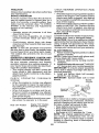
TO LEVEL MOWER
Make sure tires are properly inflated to the
PSI shown on tires. Iftires are over or under
inflated, it may affect the appearance of your
lawn and lead you to think the mower is not
adjusted properly.
VISUAL SIDE-TO-SI DE ADJUSTMENT
1. With all tires properly inflated and if your
lawn appears unevenly cut, determine
which side of mower is cutting lower.
NOTE: As desired, you can raise the low
side of mower or lower the high side.
2. Go to side of mower you wish to adjust.
3. With a 3/4" or adjustable wrench, turn
lift link adjustment nut (A) to the left to
lower the mower, or, to the right to raise
the mower.
Turn nut ri
to iraise mower
- tffront tip of blade is not 1/8" to 1/2" lower
than the rear tip, go to the front of tractor.
• With an I1/I6" or adjustable wrench,
loosen jam nut A several turns to clear
adjustment nut B.
• With a 3/4" or adjustable wrench, turn
front link adjustment nut (B) clockwise
(Itighten) to raise the front of mower, or,
counterclockwise (loosen) to lower the
front mower.
Turn nut left
to lower mower
NOTE: Each full turn of adjustment nut will
change mower height about 3/16".
4. Test your adjustment by mowing some
uncut grass and visually checking the
appearance. Readjust, ifnecessary, until
you are satisfied with the results.
PRECISION SIDE-TO-SIDE ADJUSTMENT
!. With alltires properly inflated,parktractor
on level ground or driveway.
CAUTION: Blades are sharp. Protect
your hands with gloves and/or wrap blade
with heavy cloth.
2. Raise mower to its highest position.
3. At both sides of mower, position blade at
side and measure the distance (A) from
bottom edge of blade to the ground. The
dist_nceshould bethesameon bothsides.
'
4. If adjustment is necessary, see steps 2
and 3 in Visual Adjustment instructions
above.
5. Recheck measurements, adjust ifnecessary until both sides are equal.
FRONT-TO-BACK ADJUSTMENT
IMPORTANT: Deck must be level sideto-side.
To obtain the best cutting results, the mower
blades should be adjusted so the front tip is
1/8" to 1/2" lower than the rear tip when the
ov_eris in its highest position.
AUTION: Blades are sharp. Protect
your hands with gloves and/or wrap blade
with heavy cloth.
• Raise mower to highest position.
. Position any blade so the tip is pointing
straightforward. Measure distance (B) to
the grou nd atfront and reartip ofthe blade.
Tighten adjust nut
B to raise mower
Loosen adjust
nut Bto lower
mower
Loosenjam nut A first
NOTE: Each full turn of the adjustment nut
will change mower height about 1/8".
• Recheck measurements, adjust if necessary until front tip of blade is 1/8" to 1/2"
lower than the rear tip.
• HoldadjuslTnentnut inposition withwrench
and tighten jam nut securely against adjustment nut.
A
27
TO REPLACE MOWER DRIVE BELT
MOWER DRIVE BELT REMOVAL
1. Park tractor on a level surface. Engage
parking brake.
2. Lower attachment lift lever to its lowest
position.
3. Disengage belt tension rod (K) from lock
z,_bracket (L).
_OAUTION:
Belttension rod isspring loaded. Have afirm grip on rod and releaseslowly,
4. Remove screws (P) from R,H. and L.H.
mandrel covers and remove covers (Q).
5, Remove anydirt or grass clippings which
may have accumulated around mandrels
and entire upper deck surface,
6. Remove belt from electric clutch pulley
(M), both mandrel pulleys (R) and all idler
pulleys (S).
NOTE: Observe entire motion drive belt and
position of all belt guides and keepers.
2. Disconnect clutch wire harness (A).
3. Removeanti-rotation link (B) on rightside
of tractor.
4. Remove beltfrom stationary idler (C) and
clutching idler (D).
5. Pull belt slack toward rear of tractor.
Carefully remove belt upwards from
transmission input pulley and over cooling fan blades (F).
6. Remove belt downward from engine
pulley and around electric clutch (G).
7. Slide belt toward rear of tractor, off the
steering plate (H)and remove fromtractor.
\
MOWER DRIVE BELT INSTALLATION
1. Install belt around both mandrel pulleys
(R) andaround idler pulleys (S) as shown.
2. Install belt onto electric clutch pulley (M).
IMPORTANT: Check belt for proper routing
in all mower pulley grooves.
3. Reassemble R.H. and L.H. mandrel covers (Q). Securely tighten all screws.
4. Engage belt tension rod (K) on locking
bracket (L).
CAUTION: Belt tension rod is spring loaded. Haveatight gripon rod andengageslowiy.
5. Raise attachment lift lever to highest
position.
TO REPLACE MOTION DRIVE BELT
Park the tractor on level surface. Engage
parking brake. For assistance, there is a
belt installation guide decal on bottom side
of left footrest,
BELT REMOVAL 1, Remove mower (See "TO REMOVE
MOWER" in this section of manual).
28
BELT INSTALLATION 1. Install new belt from tractor rear to front,
over the steering plate (H) and above
clutch brake pedal shaft (J),
2, Pull belttoward front oftractor and roll belt
around electric clutch and onto engine
pulley (G).
3, Pull belt toward rear of tractor. Carefully
work belt down around transmission
cooling fan and onto the input pulley (F).
Be sure belt is inside the belt keeper,
4. Install belt through stationary idler (C)
and clutching idler (D),
5. Reinstall anti-rotation link (B) on right
side of tractor. Tighten securely.
6. Reconnect clutch harness (A).
7. Make sure belt is in all pulley grooves
and inside all belt guides and keepers.
8. Install mower (See "TO INSTALL MOWER" in this section of manual).
TO CHECK BRAKE
If tractor requires more than five (5) feet to
stop at highest speed in highest gear on a
level, dry concrete or paved surface, then
brake must be serviced.
You may also check brake by:
1. Park tractor on a level, dry concrete or
paved surface, depress brake pedal all
the waydown and engage parking brake.
2. Disengage transmission
by placing
freewheel control in "transmission disengaged" position. Pull freewheel control
out and into the slot and release so it is
held in the disengaged position.
The rear wheels must lock and skid when
you try to manually push the tractor forward.
If the rear wheels rotate, then the brake
needs to be serviced. Contact a Sears or
other qualified service center.
FRONT WHEEL TOE-IN/CAMBER
Your newtractor front wheeltoe-in and camber is set at the factory and is normal. The
front wheeltoe-in and camber are notadjustable. If damage has occurred to affect the
factory set front wheel toe-in or camber, contacta Sears or other qualified service center.
TO REMOVE WHEEL FOR REPAIRS
I. Block up axle securely.
2. Remove axle cover, retaining ring and
washers to allow wheel removal (rear
wheels have a square key- Do not lose).
3. Repair tire and reassemble.
NOTE: On rearwheels only: align grooves in
rear wheel hub and axle. Insert square key.
4. Replacewashers and snap retaining ring
securely in axle groove,
5. Replace axle cover.
NOTE: To seal tire punctures and prevent
flat tires due to slow leaks, purchase and
usetire sealant from Sears. Tire sealant also
prevents tire dry rot and corrosion.
TO REMOVE
CABLES,
REVERSE
ORDER
1. BLACK cable first from chassis andthen
from the fully charged battery,
2. RED cable lastfrom both batteries.
Weak or Dead
Battery
Washers
Retaining
Ring
Axle Cover
TO START ENGINE WITH A WEAK BATTERY
A0kWARNING: Lead-acid batteries generate explosive gases. Keep sparks, flame
and smokingmaterials away from batteries.
Always wear eye protection when around
batteries.
Ifyourbatteryistooweak tostartthe engine,it
should be recharged. (See "BATTERY" inthe
MAINTENANCE section of this manual).
If "jumper cables" are used for emergency
starting, follow this procedure:
IMPORTANT: Your tractoris equipped with
a 12voltsystem. The othervehicle mustalso
be a 12 volt system. Do not use your tractor
battery to start other vehicles,
TO ATTACH JUMPER CABLES
1. Connect one end of the RED cable to the
POSITIVE (+) terminal of each battery(AB),taking care notto short againsttractor
chassis.
2. Connect one end of the BLACK cable
to the NEGATIVE (-) terminal (C) of fully
charged battery.
3. Connect the other end of the BLACK
cable (D) to good chassis ground, away
from fuel tank and battery.
'_Square
Key (Rear
Wheel Only)
29
Fully Charged
Battery
REPLACING BATTERY
_LWARNING: Do notshort batteryterminals
by allowing a wrench or any other object to
contact both terminals at the same time,
Before connecting battery, remove metal
bracelets, wristwatch bands, rings, etc.
Positive terminal must be connected first to
prevent sparking from accidental grounding.
1. Lift hood to raised position.
2. Disconnect BLACK battery cable (A)then
RED battery cable and carefully remove
battery from tractor.
3. Install new battery with terminals in same
position as old battery,
4. First connect RED battery cable (B) to
positive (+) battery terminal with hex bolt
and keps nutas shown. Tighten securely.
Slide terminal cover (C) over terminal
5. Connect BLACKgrounding cableto negative (-) battery terminal with remaining
hex bolt and keps nut. Tighten securely.
6. Close hood.
Negative
(Black)
Cable
TO REMOVE HOOD AND GRILL
ASSEMBLY
1. Raise hood.
2. Unsnap headlight wire connector.
3. Stand in front of tractor, Grasp hood at
sides, tilt toward engine and lift off of
tractor.
4. When replacing hood, besureto reconnect
the headlight wire connector.
_n
H°°d
HeadlightWire
nector
TRANSMISSION REMOVAL/REPLACEMENT
Should your transmission require removal
for service or replacement, it should be
purged after reinstallation and before operating the tractor. See "PURGE TRANSMISSION" in the Operation section of this
manual
ENGINE
TO ADJUST THROTTLE
CONTROL
CABLE
The throttle control has been preset at
the factory and adjustment should not be
necessary Check adjustment as described
below before loosening cable. If adjustment
is necessary, see engine manual.
TO ADJUST CHOKE CONTROL
The choke control has been preset at
the factory and adjustment should not be
necessary, if adjustment is necessary, see
engine manual,
TO ADJUST CARBURETOR
Your carburetor has been preset atthe factory
and adjustment should not be necessary,
However, minor adjustment may be required
to compensate for differences in fuel, temperature, altitude Or load, If the engine does
need adjustment, see engine manual.
Positive
(Red)
Cable
TO REPLACE HEADLIGHT BULB
1. Raise hood.
2. Remove bulb holder fromthe hole inthe
backside of the grill.
3, Replace bulb in holder and install bulb
holder securely back into the hole in the
backside of the grill.
4. Close hood.
INTERLOCKS AND RELAYS
Loose or damaged wiring may cause your
tractor to run poorly, stop running, or prevent
it from starting.
• Check wiring.
TO REPLACE FUSff
Replace with 30 amp automotive-type plugin fuse. The fuse holder is located behind
the dash.
30
Immediately prepare your tractor for storage
at the end of the season or if the tractor will
nAotbe used for 30 days or more.
4BLWARNING: Never store the tractor with
gasoline in the tank inside a building where
fumes may reach an open flame or spark.
Allow the engine to cool before storing in
any enclosure.
TRACTOR
Remove mower from tractor for winter
storage. When mower is to be stored for a
period of time, ctean it thoroughly,remove
all dirt, grease, leaves, etc. Store in a clean,
dry area.
1. Clean entire tractor (See "CLEANING"
in the Maintenance section of this
manual).
2, Inspect and replace belts, if necessary
(See belt replacement instructions in the
Service and Adjustments section of this
manual),
3. Lubricate as shown in the Maintenance
section of this manual.
4. Be sure that all nuts, bolts and screws
are securely fastened. Inspect moving
parts for damage, breakage and wear.
Replace if necessary.
5. Touch up all rusted or chipped paint
surfaces; sand lightly before painting.
BATTERY
- Fully charge the battery for storage.
- After a period of time in storage, battery
may require recharging.
* To help prevent corrosion and power
leakage during long periods of storage,
battery cables should be disconnected
and battery cleaned thoroughly (see "TO
CLEAN BATTERY AND TERMINALS" in
the Maintenance section of this manual).
. After cleaning, leave cables disconnected
and place cabtes where they cannot come
in contact with battery terminals.
. If battery is removed from tractor for
storage, do not store battery directly on
concrete or damp surfaces,
31
ENGINE
FUEL SYSTEM
IMPORTANT: It is important to prevent
gum deposits from forming in essential fuel
system parts such as carburetor, fuel hose,
ortank during storage. Also, alcohol blended
fuels (calted gasohol or using ethanol or
methanol) can attract moisture which leads
to separation and formation of acids during
storage. Acidic gas can damage the fuel
system of an engine while in storage.
• Emptythe fuel tank by starting the engine
and letting it run until the fuel lines and
carburetor are empty.
• Never use engine or carburetor cleaner
products in the fuel tank or permanent
damage may occur.
- Use fresh fuel next season.
NOTE; Fuel stabilizer is an acceptable
alternative in minimizing the formation of
fuel gum deposits during storage. Add
stabilizer to gasoline in fuel tank or storage
container. Always follow the mix ratio found
on stabilizer container. Run engine at least
10 minutes after adding stabilizer to allow
the stabilizer to reachthe carburetor, Do not
empty the gas tank and carburetor if using
fuel stabilizer.
ENGINE OIL
Drain oil (with engine warm) and replace
with clean engine oU. (See"ENGINE" inthe
Maintenance section of this manual).
CYLINDER(S)
1. Remove spark plug(s).
2. Pour one ounce of oil through spark plug
hole(s) into cylinder(s),
3. Turn ignition key to start position for a
few seconds to distribute oil.
4. Replace with new spark plug(s).
OTHER
• Do not store gasoline from one season to
another,
• Replaceyour gasoline can ifyour can starts
to rust. Rust and/or dirt in your gasoline
will cause problems.
• If possible, store your tractor indoors and
cover itto give protection from dust and dirt,
• Cover your tractor with a suitable protective cover that does not retain moisture,
Do not use plastic. Plastic cannot breathe
which allows condensation to form and will
cause your tractor to rust.
IMPORTANT: Never cover tractor while
engine and exhaust areas are still warm.
TROUBLESHOOTING CHART:
See appropriate section in manual unless directed to Sears service center
PROBLEM
Wig not start
CAUSE
CORRECTION
1
Out of fuel.
2
Engine net "CHOKED"
I
3
! Fill fuel tank.
2
See "TO START ENGINE" in
Operation section.
Engine fiooded.
3
Wait several minutes before
attempting to start,
4
Bad spark plug,
4
Replace spark plug,
5
Dirty air filter.
5
Clean/replace
6
Dirty fuel filter,
6
Replace fuel filter,
7
Water in fuel,
7
Empty fuel tank and carburetor,
refill tank with fresh gasoline and
replace fuel filter.
8
Loose or damaged wiring,
8
Check all wiring,
9
Carburetor
9
See "To Adjust Carburetor" in
Service and Adjustments section.
10
Contact a Sears or other qualified
service center,
10
properly.
out of adjustment,
Engine valves out of adjustment.
air filter.
1
Dirty air filter,
1
Clean/rep]ace
2
Bad spark plug,
2
Replace spark plug.
3
Weak or dead battery.
3
Recharge or replace baltery.
4
Dirty fuel filter,
4
Replace fuel filter.
5
Stale or dirty fuel,
i 5
air filter.
Empty fuel tank and refill tank with
fresh, clean gasoline.
6
Loose or damaged wiring,
6
Check all wiring.
7
Carburetor
7
See "To Adjust Carburetor" in
Service and Adjustments section.
8
Engine valves out of adjustment.
8
Contact a Sears or Other qualified
service center.
out of adjustment.
,,,,,,,....
Engine will not
turn over
1
Clutch/brake
2
Attachment
3
4
pedal not depressed.
1
Depress dutch/brake
2
Disengage
Weak or dead battery.
3
Recharge or replace battery,
Blown fuse,
4
Replace fuse.
5
Corroded battery terminals.
5
Clean battery terminals,
6
Loose or damaged widng.
6
Check all wiring.
7
Faulty ignition switch,
7
Check/replace
ignition switch.
8
Faulty solenoid
or starter.
8
Check/replace
solenoid or starter.
9
Faulty operator
switch(es).
presence
9
Contact a Sears or other qualified
sewice center.
clutch is engaged,
32
pedal.
attachment
CILrteh.
TROUBLESHOOTING CHART:
See appropriate section in manual unless directed to Sears service center
CAUSE
PROBLEM
Engine clicks but
will not start
Loss of power
, ,
Excessive
vibration
CORRECTION
1
Weak or dead battery.
1
Recharge or replace battery.
2.
Corroded
battery terminals,
2
clean battery terminals,
3
Loose or damaged wiring,
3
Check all wiring,
4
Faulty solenoid
4
Check!replace solenoid or starter,
1
Cutting too much grass/loo fast.
1
Raise cutting height/reduce
2
Throttle in "CHOKE"
position,
2
Adjust throttle control.
3
Build-up of grass, leaves and
trash under mower.
3
Clean underside of mower
housing.
4
Dirty air filter.
4
Clean/replace
5
Low oil leveVdirty oiI.
5
Check oil level/change
6
Faulty spark plug.
6
Clean& regaporchange
7
Dirty fuel filter.
7
Replace fuel filter.
8
Stale or dirty fuel.
8
Empty fuel tank and refill tank wJti"
fresh, clean gasoline.
9
Water in fuel.
9
Empty fuel tank and carburetor,
refill tank with fresh gasoline and
replace fuel filter.
or starter.
loose.
speed
air filter.
oil.
spark plug
10
Spark p[ugwire
10
Connect & tighten spark plug wire
11
Dirty engine air screen/fins.
11
Clean engine airscreen!fins.
12
Dirty/clogged muffler.
12
Clean/replace
13
Loose or damaged wiring.
13
Check all widng.
14
Carburetor out of adjustment.
14
See "To Adjust Carburetor" in
Service and Adjustments section.
15
Engine valves out of adjustment.
15
Contact a Sears or other qualified
service center.
muffler.
, ,, ,,, ,I,,,u,,,,,,,,,I
1
Worn, bent or loose blade,
1
Replace blade, Tighten blade bolt
2
Bent blade mandrel.
2
Contact a Sears or other qualified
service center,
3
Loose!damaged
,3 Tighten loose part(s),
Repiace damaged parts.
Engine continues to
1
run when operator
leaves seat with attachment clutch engaged
part(s).
Faulty operator-safety presence
control system.
33
I
Check wiring, switches and
connections. If not corrected,
contact a Sears or other
TROUBLESHOOTING CHART:
See appropriate section in manual unless directed to Sears service center
CAUSE
PROBLEM
Poor cut - uneven
cutting
Mower blades
not rotate
well
Poor grass
discharge
CORRECTION
Replace
blad
g.;ghtan
blade
bo,t.
1
Worn, bent or loose blade,
2
Mower deck not level.
2.
Level mower deck,
3
Buildup of grass, leaves, and
trash under mower,
3
Glean underside
housing.
4
Bent blade mandrel,
4
of mower
Contact a Sears or other
qualified service center.
Clogged mower deck vent from
build-up of grass, leaves, and
trash around mandrels,
5
Clean around mandrels to
open vent holes.
1
Obstruction
1
Remove obstruction,
2
Worn/damaged
2
Replace mower drive belt.
3
Frozen idler pulley.
3
Replace idler pulley,
4
Frozen blade mandrel.
4
Contact a Sears or other
qualified service center.
1
Engine speed too slow,
1
Place throttle control in "FAST"
position,
2
Travel speed too fast.
2
Shift to slower speed,
3
Wet grass.
3
Ailow grass to dry before mowing.
4
Mower deck not level.
4
Level mower deck.
5
Low/uneven
5
Check tires for proper PSI.
6
Worn. bent or loose blade.
6
Replace/sharpen
blade bolt.
7
Buildup of grass, leaves and
trash under mower.
7
Clean underside
housing.
8
Mower drive belt worn.
8
Replace mower drive belt.
9
Blades improperly installed,
g
Reinstall blades sharp edge down.
in clutch mechanism,
mower
drive belt
tire air pressure.
blade. Tighten
of mower
10
Improper blades used.
11
Clogged mower deck vent holes
11
from buildup of grass, leaves, and
trash around mandrels.
Clean around mandrels
open vent holes.
1
Turn light switch "ON".
10
Replace with blades listed in
this manual,
to
, , ,, ,,, ,,,
Headlight(s)
not
working
(if so equipped)
1
Light switch is "OFF".
2
Bulb(s) or lamp(s) burned out.
i2
Replace bulb(s) or lamp(s).
3
Faulty light switch.
i3
Check/replace
4
Loose or damaged wiring.
i4
Check wiring and connections,
5
Blown fuse,
5
34
Replace fuse.
light switch.
TROUBLESHOOTING CHART:
See appropriate section in manual unless directed to Sears service center
.......... CAUSE
PROBLEM
Battery
charge
witl not
Loss of drive
CORRECTION
1
Bad battery cell(s),
1
Replace battery.
2
Poor cable connections.
2
Check/clean
3
Faulty regulator (if so equipped).
3
Replace regulator.
all connections,
4
Faulty alternator.
4
Replace alternator,
1
Freewheel control in
"DISENGAGED" position,
1
Place freewheel control in
=ENGAGED" posffion.
2
Debris on steering piate (if
equipped).
2
See "CLEANING" in the
maintenance section.
3
Replace motion drive belt,
3
Motion drive belt worn, damaged,
i or broken.
4 i Air trappedin transmission during 4
i shipmentor servicing.
Purge transmission,
5
Install axis key at rear wheel, See
"TO REMOVE WHEEL" in the
Service and Adjustments section.
i Axle key missing.
,,, ,,,,,.......
Engine "backfires"
when turning
engine "OFF"
1
Engine throttle control not sel
between haft and full speed (_st)
position before stopping engine,
1
Move throttle control between
half and full speed (,fast) position
before stopping engine.
1
Reverse operation system (ROS)
is not "ON" while mower or other
attachment is engaged.
1
Turn ignition key to ROS "ON"
position. See Operation section.
, ,, ,,,,,,,,,,,
, ,,,,,,,,,,
.....
Engine dies when
tractor is shiftea
into reverse
35
36
37
38
m
I
i
I
I
I
I
o,_'= o
I
_o_
m
-.4
m
0
c;
o
m
"rl
0
33
_0
0
-r"
-.4
_
r"
0
"0
m
I
I
I
I
I
I¢1
i
I
I
I
"n
0
33
_3
=fl
m
0
"0
m
;D
-.-!
0
Z
39
NEED MORE HELP?
You'[[ find the answe_ and more on managemyhome.com
. F_nd this
and all your other product manuals
- for free!
online.
• Getanswers
from ourteamof homeexperts.
• Geta personalizedmaintenancepLanfor yourhome.
• Findinformationandtook to helpwith homeprojects.
manage_home
_b_ht
te _u
5y $_.'ars
Your Home
For repair- in your home - of all major brand appliances,
lawn and garden equipment, or heating and cooling systems.
no matter who made it, no matter who sold it!
For the replacement parts, accessories and
owner's manuals that you need to do-it-yourseff.
For Sears professional installation of home appliances
and items like garage door openers and water heaters.
1-800-4-MY-HOME
®
Anytime,
(1-800-469-4663)
www.seats.com
day or night
(U.S.A. and Canada)
www.sears.ca
Our Home
For repair of carry-in products like vacuums, lawn equipment.
and electronics, call or go on-fine for the nearest
Sears Parts and Repair Center.
1-800-488-1222
@
Anytime,
day or ni_lht (U,S,A. only)
www=seal_,Collrl
To purchase a proteclion agreement (U.S.A.)
or maintenance agreement (Canada) on a product serviced by Sears:
1-800-827-6655 (U.SA.)
1-800-361-6665 (Canada)
Para pedirse_cio de reparaciSn
Au Canada pour serviceen francis:
a domicilio,y para ordenarpiezas:
t"888"SU'HOGAR_
___
1-800"LE'FOYER_C
(1-888-784-6427)
©S_sBr',-,-,-,-,-,-,-,-_,LLC
® Registered
Trademalk
1T_-rrademark
/ meService
Mark ef Sears
Brsn_s,
LLC
® Mama Reg;atrada1 _ Mama de F,tbzicaI s_ Mama de Setvicie de Sears Brands, LLC
Marque de cornmeme/ _ Marque d_pes_e de Sears Brands, LLC
01.10.11 BAD
Printed in the U.S.A.