1
Operator's
Manual
[RRFT$1VIRW
LAWN
TRACTOR
26.0 HP,*54" Mower
ElectricStart
Automatic Transmission
Model No.
917.28858
- Espa_ol, p. 37
,{ _
l
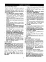
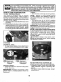
This product has a low emission engine which operates
differently from previously built engines. Before you start the
engine, read and understand this Owner's Manual.
IMPORTANT:
Read and follow all Safety
Rules and Instructions
before
operating this equipment.
For answers to your questions
about thisproduct,Call:
1-800-659-5917
Sears Craftsman Help Line
5 am - 5 pro, Mon - Sat
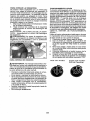
Gasoline containing up to 10% ethanol (El0) is acceptable for use in this machine.
The use of any gasoline exceeding 10% ethanol (El0) will void the product warranty.
Esta mdquina puede utilizar gasolina con un contenido de hasta el 10% de etanol (El0).
El uso de una gasolina que supere el 10% de etano| (EIO) anulard la garantfa del producto.
Sears Brands Management Corporation, Hoffman Estates, IL 60179 U.S.A.
Visit our Craftsman
448212
website:www.sears.com/craftsman
....
*_
rated bythe engine manufacturer
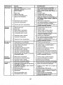
Maintenance .......................................... 21
Service and Adjustments ....................... 26
Storage .................................................. 31
Troubleshooting ..................................... 32
Sears Service .......................... Back Cover
Warranty ..................................................
2
Safety Rules ............................................
3
Product Specifications
.............................
6
Assembly/Pre-Operation
.........................
7
Operation ...............................................
13
Maintenance
Schedule ..........................
2!
Craftsman Riding Equipment Warranty
CRAFTSMAN FULL WARRANTY
FOR TWO YEARS from the date of purchase, all non-expendable parts of this riding equipment are
warranted against any defects in material or workmanship. A defective non-expendable part wilt
receive free in-home repair or replacement if repair is impossible.
FOR FIVE YEARS from the date of purchase, the frame and front axle of this riding equipment are
warranted against any defects in material or workmanship. A defective frame or front axle will receive
free in-home repair or replacement if repair is impossible.
FOR 90 DAYS from the date of purchase, the battery (an expendable part) of this riding equipment
is warranted against any defects in matedal or workmanship (our testing proves that it will not hold a
charge). A defective battery will receive free in-home replacement.
ADDITIONAL LIFETIME LIMITED WARRANTY on CAST IRON FRONT AXLE (if equipped)
FOR AS LONG AS IT IS USED by the original owner after the fifth year from the date of purchase, the
cast iron front axle (ifequipped) of thisriding equipmentJswarranted against any defectsin material or
workmanship. With proof ofpurchase, a defectivecast frontaxle will receive free in-home replacement.
WARRANTY SERVICE
For warranty coverage details to obtain free repair or replacement, call 1-800_659-5917 or visitthe
web site: www.craftsman.cem
In all cases above, if part repair or replacement is impossible,the ridingequipment wilt be replaced
free of charge with the same or an equivalent model
All of the above warranty coverage is void if this riding equipment is ever used whiJe providing
commercial services or if rented to another person.
This warranty covers ONLY defects in material and workmanship. Warranty coverage does NOT
include:
* Expendable parts (except battery) that can wear out from normal use within the warranty period,
including but not limited to blades, spark plugs, air cleaners, belts, and oil filters.
* Standard maintenance servicing, oi!changes, or tune-ups.
, Tire replacement or repair caused by punctures from outside objects, such as nails, thorns,
stumps, or glass.
- Tire or wheel replacement or repair resultingfrom normal wear, accident, or improperoperation or
maintenance.
• Repairs necessary because of operator abuse, including but not limited to damage caused by
towing objects beyond the capability of the riding equipment, impacting objects that bend the
frame, axle assembly or crankshaft,or over-speeding the engine.
. Repairs necessary because of operator negligence, including but not limited to, electrical and
mechanical damage caused by improper storage, failure to use the proper grade and amount
of engine oil, faiJure to keep the deck clear of flammable debris, or failure to maintain the riding
equipment according to the instructions contained in the operator's manual.
. Engine (fuel system) cleaning or repairs caused byfuel determined to be contaminated or oxidized
(stale). In general, fuel should be used within 30 days of its purchase date.
, Normal deterioration and wear of the exteriorfinishes, or product Jabel replacement.
This warranty gives you specific legal rights, and you may also have other rights which vary from
state to state.
Sears Brands
Management
Corporation,
Hoffman
2
Estates,
IL 60179
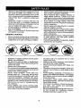
t_roDANGER: This cutting machine is capable of amputating hands and feet and
wing objects. Failure to observe the following safety instructions could result
in serious injury or death.
_I, WARNING: In order to preventaccidental starting when setting up, transporting,
adjusting or making repairs, always disconnect spark plug wire and place wire where
it cannot contact spark plug.
•
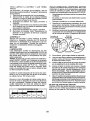
d_IbWARNING: Do not coast down a hill in
neutral, you may lose control of the tractor.
•
_WARNING:
Tow only the attachments
that are recommended by and comply with
specifications of the manufacturer of your
tractor. Use common sense when towing,
Operate only at the lowest possible speed
when on a slope, Too heavy ofatoad, while
on a slope, is dangerous, Tires can lose
traction with the ground and cause you to
lose control of your tractor.
•
•
•
_WARNING:
Engine exhaust, some of
its constituents, and certain vehicle components contain or emit chemicals known to
the State of California to cause cancer and
birth defects or other reproductive harm.
•
•
•
_&WARNING: Battery posts, terminals and
related accessories contain lead and lead
compounds, chemfcals known tothe State of
California to cause cancer and birth defects
or other reproductive harm, Wash hands
after handling,
•
•
•
I. GENERAL OPERATION
• Read, understand,andfollowall instructions on the machine and in the manual
before starting,
• Do not put hands or feet near rotating
parts or under the machine. Keep clear
of the discharge opening at all times.
• Only allow responsible adults, who are
familiar with the instructions, to operate
the machine,
• Clear the area of objects such as rocks,
toys, wire, etc,, which could be picked
up and thrown by the blades.
• Be sure the area Jsclear of bystanders
before operating, Stop machine if anyone
enters the area.
- Never carry passengers.
• Do not mowin reverse unless absolutely
necessary. Always Iookdown and behind
before and while backing.
•
•
3
Never direct discharged materiattoward
anyone. Avoid discharging material
against a wall or obstruction, Material
may ricochet back toward the operator.
Stop the blades when crossing gravel
surfaces.
Do not operate machine without the entire grass catcher, discharge chute, or
other safety devices in place and working.
Slow down before turning.
Never leave a running machine unattended. Always turn off blades, set
parking brake, stop engine, and remove
keys before dismounting.
Disengage blades when not mowing.
Shut off engine and wait for all parts to
come to a complete stop before cleaning
the machine, removing the grass catcher,
or unclogging the discharge chute,
Operate machine only indaylight orgood
artificial light.
Do not operate the machine while under
the influence of alcohol or drugs.
Watch for traffic when operating near or
crossing roadways,
Useextracare when loading or unloading
the machine into a trailer or truck.
AIwaysweareye protectionwhen operating machine.
Data indicates that operators, age 60
years and above, are involvedin a large
percentage of ridingmower-related injuries. These operators should evaluate
their ability to operate the riding mower
safely enough to protect themselves and
others from serious injury.
Followthe manufacturer's recommendation forwheelweights or counterweights.
Keep machine free of grass 0leaves or
other debris build-upwhich can touch hot
exhaust f engine parts and burn. Do not
allow the mower to plow leaves or other
debris which can cause build-up to occur. Clean any oil or fuel spillage before
operating or storing the machine, Allow
machine to cool before storage,
II, SLOPE OPERATION
•
Slopes are a major factor related to loss of
control and tip-over accidents, which can
result in severe injuryor death. Operation
on all slopes requires extra caution. If you
cannot back up the slope or if you feel uneasy
on it, do not mow it.
- Mow up and down slopes, not across.
• Watch for holes, ruts, bumps, rocks, or
other hidden objects. Uneven terrain
could overturn the machine. Tall grass
...........
can hide obstacles.
• Choose a low ground speed so that you
will not have to stop or shift while on the
slope.
•
Do not mew on wet grass. Tires may lose
traction.
Always keep the machine in gear when
going down slopes. Do not shift to neutral
and coast downhill.
• Avoid starting, stopping, or turning on a
slope. Ifthetires losetraction, disengage
the blades and proceed slowly straight
down the slope.
• Keep all movement on the slopes slow
and gradual.
Do not make sudden
changes in speed or direction, which
could cause the machine to roll over,
• Use extra care while operating machine
with grass catchers or other attachments;
they can affect the stability of the machine, Do no use on steep slopes.
• Do not try to stabilize the machine by
putting your foot on the ground,
• Do not mow near drop-offs, ditches.
or embankments. The machine could
suddenly roll over if a wheel is over the
edge or if the edge caves in,
iii, CHILDREN
_WARNING:
CHILDREN
CAN BE INJURED
BYTHIS EQUIPMENT.The American Academy of Pediatrics recommends that children
be a minimum of 12 year of age before operating a pedestrian controlled lawn mower
and a minimum of 16 years of age before
operating a riding lawn mower.
Tragic accidents can occur if the operator
is not alert to the presence of children.
Children are often attracted to the machine
and the mowing activity, Never assume
that children wilt remain where you last
saw them.
Keep children out of the mowing area
and in the watchful care of a responsible
adult other than the operator.
° Be alert and turn machine off ff a child
enters the area.
° Before and while backing, look behind
and down for small children.
- Never carry children, evenwiththe blades
shutoff, They mayfall off andbe seriously
injured or interfere with safe machine
operation, Children who have been given
rides in the past may suddenly appear in
the mowing area for another ride and be
run over or backed over by the machine.
• Never allow children to operate the machine.
• Use extra care when approaching blind
corners, shrubs, trees, or other objects
that may block your view of a child.
IV. TOWING
• Tow only with a machine that has a hitch
designed for towing, Do not attach towed
equipment except at the hitch point,
• Followthe manufacturer's recommendation for weight limits for towed equipment
and towing on slopes.
• Never allow children or others in or on
towed equipment,
• On slopes, theweight ofthetowed equipment may cause loss oftraction and loss
of control.
° Travelslowly and allow extra distance to
stop.
V. SERVICE
SAFE HANDLING OF GASOLINE
To avoid personal injury or property damage, use extreme care in handling gasoline.
Gasoline is extremely flammable and the
vapors are explosive.
o Extinguish all cigarettes, cigars, pipes,
and other sources of ignition.
• Use only approved gasoline container.
• Never remove gas cap or add fuel with
the engine running. Allow engine to cooi
before refueling,
, Never fuel the machine indoors.
• Never store the machine or fuel container
where there is an open flame, spark, or
pilot light such as on a water heater or
ether appliances.
° Never fill containers inside a vehicle or
on a truck or trailer bed with plastic liner.
Always place containers on the ground
away from your vehicle when filling.
|
•
Remove gas-powered equipment from
the truck or trailer and refuel it on the
ground, tfthis is not possible, then refuel
such equipmentwith a portable container,
rather than from a gasoline dispenser
nozzle.
• Keep the nozzle in contact with the rim
of the fuel tank or container opening at
all times until fueling is complete. Do not
use a nozzle lock-open device.
• iffuel is spilled on clothing, change clothing immediately.
• Never overfil] fuel tank. Replace gas cap
and tighten securely.
GENERAL SERVICE
•
•
•
•
•
•
•
•
•
•
•
•
•
•
Never operate machine in aclosed area.
Keep all nuts and bolts tightto be surethe
equipment is in safe working condition.
Maintain or replacesafety and instruction
labels, as necessary.
Be sure the area is clear of bystanders
before operating. Stop machine if anyone
enters the area.
Never carry passengers.
Do not mow in reverse unless absolutely
necessary. Always look down and behind
before and while backing.
Never carry children, even with the
blades shut off. They may fall off and
be seriously injured or interfere with safe
machine operation. Children who have
been given rides inthe past may suddenly
appear in the mowing area for another
ride and be run over or backed over by
the machine.
Keep children out of the mowing area
and in the watchful care of a responsible
adult other than the operator_
•
•
•
•
.
-
•
•
•
Never tamper with safety devices. Check
their proper operation regularly.
Keep machine free of grass, leaves, or
other debris build-up. Clean oil or fuel
spillage and remove anyfuel-soaked debris. Allow machine to coo] before storing.
If you strike a foreign object, stop and
inspectthe machine. Repair, if necessary,
before restarting.
Never make any adjustments or repairs
with the engine running.
Checkgrass catcher components andthe
discharge chute frequently and replace
with manufacturer's recommended parts,
when necessary.
Mower blades are sharp. Wrapthe blade
or wear gloves, and use extra caution
when servicing them.
Checkbrakeoparationfrequently. Adjust
and service as required.
Be alert and turn machine off if a child
enters the area.
Before and while backing, look behind
and down for small children.
Mow up and down slopes (15° Max), not
across.
Choose a low ground speed so that you
will not have to stop or shift while on the
slope.
Avoid starting, stopping, or turning on a
slope, lfthetires Iosetraction, disengage
the blades and proceed slowly straight
down the slope.
If machine stops while going uphill,
disengage blades, shift into reverse and
back down slowly.
Do not turn on slopes unless necessary,
and then, turn slowly and gradually
downhill, if possible.
When loading or unloading this machine,
do not exceed the maximum recommended operation angle of t5 °.
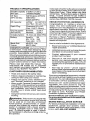
PRODUCT
SPECIFICATIONS
GasolineCapacity 3 Gallons (11,35 L)
and Type:
UnleadedRegular
Oil Type
(APh SG-SL):
SAE 30 (above32°F/0°C)
SAE 5W30
(below 32°F/0°C)
Oil Capacity:
w/Filter:
64 oz(1,9 L)
w!o Filter: 60 oz(1,7 L)
Spark Plug:
Champion QC12YC
(Gap: .040"/1,02ram)
Ground Speed
Forward:
5.2/8,4
(MPH!KPH)
Reverse:
2,9/4,7
ChargingSystem: 16 Amps @ 3600 RPM
Batten]:
Amp!Hr:
28
Min. CCA: 230
Casesize: UIR
Blade Bolt
45-55 Ft. Lbs.
Torque:
(62-75 Nm)
CONGRATULATIONS on your purchase of
a new tractor. It has been designed, engineered and manufactured to give you the best
possible dependability and performance.
Should you experience any problem you cannot easily remedy, please contact aSears or
other qualified service center. We have competent, well-trained representatives and the
proper tools to service or repair this tractor.
Please read and retain this manual. The
instructions wilt enable you to assemble
and maintain your tractor properly. Always
observe the "SAFETY RULES".
CUSTOMER
RESPONSIBILITIES
• Read and observe the safety rules.
- FoUowa regularschedule in maintaining,
caring for and using your tractor,
• Follow instructions under "Maintenance"
and "Storage" sections of this manual.
• Wear proper Personal Protective Equipment (PPE) while operating this machine,
including (at a minimum) sturdy footwear,
eye protection, and hearing protection.
Do not mow in shorts and/or open toed
footwear.
• Always letsomeone knowyou are outside
mowing.
_ILWARNING: This tractoris equipped with
an internal combustion engine and should
not be used on or near any unimproved
forest-covered, brush-covered or grasscovered land unless the engine's exhaust
system is equipped with a spark arrester
meeting applicable local or state laws (if
any). If a spark arrester is used, it should
be maintained in effective working order by
the operator.
Inthe state of Californiathe above isrequired
by law (Section 4442 of the California Public
Resources Code). Other states may have
similar laws. Federal laws apply on federal
lands. A spark arrester for the muffler is
available through your nearest Sears service
center (See REPAIR PARTS manual).
REPAIR PROTECTION AGREEMENTS
Congratulations on making a smart purchase. Your new Craftsman® product is
designed and manufactured for years of
dependable operation. But like all products,
it may require repair fromtimeto time, That's
when having a Repair Protection Agreement
can save you money and aggravation,
Purchase a Repair Protection Agreement
now and protect yourself from unexpected
hassle and expense.
Here's what's includedin the Agreement:
• Expert service by our 12,000 professionaf
repair specialists.
•
Unlimited service and no chargefor parts
and labor on all covered repairs.
•
Product replacement if your covered
product can't be fixed,
•
Discount of 10% from regular price of
service and service-related parts not
covered by the agreement; also, 10% off
regular price of preventive maintenance
check,
•
Fast help by phone - phone support
from a Sears representative on products
requiring in-home repair, plus convenient
repair scheduling.
Onceyou purchasethe Agreement, a simple
phone call is all that it takes for you to schedule service. Youcan call anytime dayor night,
or schedule a service appointment online.
Sears has over 12,000 professional repair
specialists, who have access to over 4.5
million quality parts and accessories. That's
the kind of professionalism you can count on
to help prolong the life of your new purchase
for years to come. Purchase your Repair
Protection Agreement today!
Some limitations and exclusions apply.
For prices andadditional information call
1-800.827-6655.
SEARS INSTALLATION SERVICE
For Sears professional installation of home
appliances, garage door openers, water
heaters, and other major home items, in the
U.S.A. call 1-800-4-MY-HOME®
Mower Front Wheel
Mower
©
-
(2) Rear _x
(5)1-3/16
Lift Link
O.D. Washers
,_
@
(1) Shoulder Bolt
(1) 1-1/40.D.
Washer
Assemblies _
(1) Small
Retainer Springs
(1) Front_\
Lift Link
"_,
Assembly
%
(11 3/8.16
Locknut
(1) Wheel
Retainer Springs
Slope Sheet
If Equipped
I
Keys
(1) Anti-Sway Bar
(1)3/40.D.
Washers
(2) Keys
(I) Small Retainer
Springs
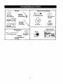
Your new tractor has been assembled at the factory with exception of those parts left unassembled for shipping purposes, To ensure safe and proper operation of your tractor all parts
and hardware you assemble must be tightened securely. Use the correct tools as necessary
to ensure proper tightness.
TOOLS
REQUIRED
FOR ASSEMBLY
•
Release lever to lock seat in position.
A socket wrench set will make assembly
easier. Standard wrench sizes are listed.
(2) 7/16" wrenches
Utility knife
(1) 1/2" wrench
Tire pressure gauge
(1) 3/4" wrench
Pliers
(I) 3/4" socket w/drive ratchet
(1) 9/16" wrench
Flashlight
When right or left hand is mentioned in this
manual, it means when you are in the operating
position (seated behind the steering wheel),
TO
REMOVE
CARTON
UNPACK
•
TRACTOR
FROM
CARTON
Rein ore all accessible loose parts and parts
cartons from carton.
Cut along dotted lines on att four panels of
carton. Remove end panels and lay side
panels flat.
Remove mower and packing materials.
Check for any additional loose parts or
cartons and remove.
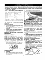
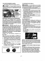
BEFORE REMOVING
FROM SKID
TO CHECK
TRACTOR
BATTERY
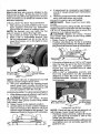
1. Lift hood to raised position.
NOTE: If this battery is put into service after
month and year indicated on label (label is
located between terminals) charge battery
for minimum of one hour at 6-10 amps. (See
"BATTERY" in Maintenance
section of this
manual for charging instructions).
•
For battery & battery cable installation see
"REPLACING BATTERY" in the "Service
and Adjustments" section in this manual.
NOTE: "Youmay now roll your tractor off the
skid. Follow the appropriate instruction below
to remove the tractor from the skid.
WARNING: Before starting, read, understand and follow allinstructions inthe Operation
section of this manual, Be sure tractor is in a
well-ventilated area. Be surethe area in front
of tractor is clear of other people and objects.
TO ROLL TRACTOR OFF SKID (See
Operation section for location and
function of controls)
1,
Raise attachment lift lever to its highest
position.
2. Release parking brake bydepressing brake
pedal.
3. Placefreewheelcontrolin
disengaged position to disengage transmission (See "TO
TRANSPORT" in the Operation section of
this manual).
4. Roll tractor forward off skid,
Continue with the instructions that follow,
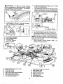
TO INSTALL
MOWER
1. SET PARKING BRAKE LEVER AND
LOWER ATTACHMENT LIFT LEVER
,
Depress clutch/brake pedal all the way
down and hold,
Pull parking brake lever up and hold, release
pressure from clutch/brake pedal, then
release parking brake lever. Pedal should
remain in brake position. Ensure parking
brake will hold tractor secure.
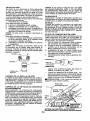
TO ADJUST SEAT
•
Sit in seat.
•
Lift up adjustment lever (A) and slide seat
until a comfortable position isreached which
allows you to press clutch/brake pedal all
the way down.
Brake Lever
3. TURN STEERING WHEEL LEFT AND
POSITION MOWER
• Turn steering wheel to the teft as far as it
willgo and positionmower on dght side of
tractorwith def[ectorshJeld(Q)to the right.
AI_CAUTION: Lift lever is spring loaded.
Have a tight grip on lift lever,lower it slowly
and engage in lowest position. Uft ]ever is
located on left side of fender.
Lift
Lever
Front
fne
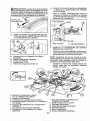
2. ASSEMBLE FRONT GAUGE WHEEL
(W) TO FRONT OF MOWER
Q, Deflector Shietd
H,
W.
X.
Y.
Z.
A.
B.
C,
D.
E,
E
H,
Front Mower Bracket
Front Gauge Wheel
Shoulder Bolt
i-1/40.D. Washer
8/8-16 Locknut
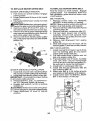
4. SLIDE MOWER UNDER TRACTOR
* Bdng belt forward and check beltfor proper routing in all mower pulley grooves.
NOTE: Be sure mower side suspension
arms (A) are pointfng forward before sliding
mower under tractor.
, Slide mower under tractor untit it iS
centered under tractor.
Mower Side Suspension Arms
Retainer Spring
Rear L_t Link(S)
Right Side Re_ Mower Bracket
Front Lift; Link Assembly
Front Suspension Bracket
Front Mower Bracket
L
K.
L
M.
Q.
S,
Wo
9
Left Side Rear Mower Bracket
Belt Tension Rod
Locking Bracket
Engine Clutch Pulley
Def(ector Shield
Anti-Sway Bar
Front Gauge Wheel
•
•
A,
Mower
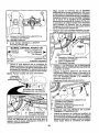
Pivot the integrated washer end of antisway bar (S)towards mower deck bracket
on right side of mower, Insert integrated
washer end of bar into hole in rear mower
bracket (D). Move mower as needed to
insert integrated washer end of bar into
rear mower bracket (D).
Secure with small washer and smatl
retainer spring as shown,
Side Sus _ension Arms
Q. DeflectorShield
5. INSTALL ANTI-SWAY BAR (S)
(IF EQUIPPED)
ANTI-SWAY
_
Towards
Towards
Transaxle
MowerDeck _m.
90° End
•
BAR (S)
D. RightSide RearMowerBracket
S. Anti-SwayBar
T. TransaxleBracket
IntegratedWasher End
z"
From right side of mower, first insert
90 ° end of anti-sway bar (S) into hole in
transaxle bracket iT), located near left
rear tire in front of transaxle,
NOTE:
Flashlight
Anti-Sway
Bar (S)
Location
may be helpful.
i"_,
_%
u._''_._'
'._:--_-Z_ I ;
I
_,,
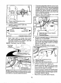
6. ATTACH MOWER SIDE SUSPENSION
ARMS (A) TO CHASSIS
• Position front hole inside suspension arm
(A) over pin on outside of tractor chassis
and secure with large washer and large
retainer spring (B).
• Repeat on opposite side of tractor.
""
Transaxle Bracket m
Located Between Rear Tires
A. Mower Side Suspension Arms
B. Retainer Spring
D. Right Side Rear Mower Bracket
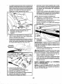
7, ATTACH REAR LIFT LINKS (C)
• Insert rod end of rear Iift link (C) into hole
(U) in tractor lift shaft suspension arm
and pivot link down to mower.
• Lift rear corner of mower and position slot
in link assembly over pin on rear mower
bracket (D) andsecure with large washer
and large retainer spring.
• Repeat on opposite side of tractor.
NOTE: Depending on model, bracket (T)may
be differe ntthan shown but holefor anti-sway
bar will be in same position!location.
10
9 INSTALL BELT ON ENGINE CLUTCH
PULLEY (M)
• Disengage belt tension rod (K) from
locking bracket (L).
- Install belt onto engine clutch pulley (M).
D. Right Side Rear Mower Bracket
Hole
8
•
ATTACH FRONT LINK (E)
Turn steering wheel to position wheels
straight forward.
• From front of tractor, insert rod end of
front link (E) through front hole in tractor
front suspension bracket (F).
Move to left side of mower and and insert
large retainer spdng (G) through hole in
front link (E) behind front suspension
bracket (F).
• Insert other end of link (E) into hole in
front mower bracket (H) and secure with
washer and small retainer spring (J).
NOTE: Requires deck lifting.
FrontLink
Location,
5.
F.
G,
H.
J.
M.
/
i
!
Z'_'_ _
(T;._.
/ .....
M.Engine
Clutch PulLey
IMPORTANT: Check belt for proper muting
in all mower pulley grooves and under
mandrel covers.
• Engage belt tension rod (K) on locking
bracket (L).
_IbCAUTION: Belt tension rod is spring
loaded. Have a tightgrip on rod and engage
slowly.
- Raise attachment lift lever to highest
position.
• If necessary, adjust gauge wheels
before operating mower as shown in the
Operation section of this manual.
MOWER DRIVE BELT INSTALLATION
Follow procedure described
in "TO
REPLACE MOWER BLADE DRIVE BELT"
in the "Service and Adjustments" section of
thismanual.
\
Front Lift Link Assembly
Front Suspension Bracket
Large Retainer Spring
Front Mower Bracket
Small Retainer Spring
Engine Clutch Pulley
11
CHECK TIRE PRESSURE
The tires onyour tractor were overinflated at
the factory for shipping purposes. Correct
tire pressure is important for best cutting
performance.
• Reduce tire pressure to PSI shown on
tires.
CHECK DECK LEVELNESS
For best cutting results, mower housing
should be properly leveled. See "TO LEVEL
MOWER" in the Service and Adjustments
section of this manual.
CHECK FOR PROPER POSITION OF
ALL BELTS
See the figures that are shown for replacing motion and mower blade drive belts in
the Service and Adjustments section of this
manual, Verify that the belts are routed
correctly.
CHECK BRAKE SYSTEM
After you learn how to operate your tractor,
check to see that the brake is operating
properly. See "TO CHECK BRAKE" in the
Service and Adjustments section of this
manual.
t_CHECKLIST
Before you operate your new tractor, we
wish to assure that you receive the best
performance and satisfaction from this
Quality Product.
Please review the following checklist:
J All assembly instructions have been
completed.
v( No remaining loose parts in carton.
J" Battery is properly prepared and
charged,
vf Seat is adjusted comfortably and tightened securely.
J" AIt tires are properly inflated. (For shipping purposes, the tires were overinflated
at the factory).
V" Be sure mower deck is properly leveled
side-to-sideifront-to-rear for best cutting
results. (Tires must be properlyinflated
for leveling).
J" Check mower and drive belts. Be sure
they are routed properly around pulleys
and inside alt belt keepers.
vf Check wiring. See that all connections
are still secure and wires are properly
clamped.
J" Before driving tractor, be sure freewheel
control is in "transmission engaged" position (see "To Transport" in the Operation
section of this manual).
While learning how to use your tractor, pay
extra attention to the following important
items:
_/Engine oil is at proper level.
v_ Fueltank isfilledwith fresh,clean,regular
unleaded gasoline.
J" Become familiar with all controls, their
location and function, Operate them
before you startthe engine.
v ( Be sure brake system isinsafe operating
condition,
J Be sure Operator Presence Systemand
Reverse Operation System (ROS) are
workingpropedy(See the Operation and
Maintenance sectionsin this manual).
v_ it is important to purge the transmission
before operatingyourtractor for the first
time. Follow proper starting and transmission purging instructions (See "TO
START ENGINE" and "PURGE TRANSMISSION" inthe Operation section of this
manual).
12
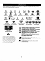
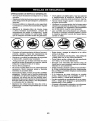
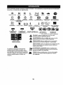
These
symbols
mayappear
onyourtractor
orinliterature
supplied
withtheproduct.
Learn
andunderstand
theirmeaning.
R
N
REVERSE
ENGINE
OFF
H
NEUTRAL
REVERSE
OPERATION
L
HIGH
I',,i
LOW
ENGINE
ON
ENGINE
CHOKE
START
PARKING
SLOW
FAST
BRAKE
MOWER
IGNITION SWITCH
HEIGHT
MOWERLIFT
SYSTEM(ROS)
LIGHTSON
FUEL
BATTERY
REVERSE
FORWARD
CRUISE
CLUTCWBRAKE
PEDAL
CONTROL
m
ATTACHMENT
CLUTCH
DISENGAGED
ATTACHMENT
CLUTCH
ENGAGED
DANGER,
KEEP HANDS
AND FEET AWAY
KEEP
AREA
CLEAR
(SEE
FREEWHEEL
(AutomaUc Modelson|y)
&
Failure to follow instructions
could result in serious injury or
death. The safety alert symbol
is used to identify safety information about hazards which can
result in death, serious injury
and/or property damage.
&
&
&
SAFET't
SLOPE
RULES
HAZARDS
eECTION)
DANGER indicates a hazard which, if not avoided,
will result in death or serious injury.
WARNING indicates a hazard which, if not avoided,
could result in death or serious injury.
CAUTION indicates a hazard which, if not avoided,
might result in minor or moderate injury.
CAUTION when used without the alert symbol,
indicates a situation that could result In damage
to the tractor and/or engine.
HOT SURFACES indieatas a hazard which_
if not avoided, could result in death, serious injury
and/or property damage.
FIRE indicates a hazard which, if not avoided,
could result In death, serious Injury and/or
property damage.
13
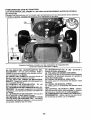
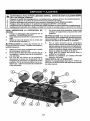
KNOW YOUR TRACTOR
READ THIS OPERATOR'S MANUAL AND SAFETY RULES BEFORE OPERATING
YOUR TRACTOR
Compare the illustrationswith your tractorto familiarize yourself with the locations of
various controls and adjustments. Save this manual for future reference.
Our tractors conform to the applicable safety standards of the
American National Standards Institute.
(A) ATTACHMENT LIFT LEVER - Used to
raise and lower the mower or other attachments mounted to your tractor.
(H) LIGHT SWITCH - Turns the headlights
on and off.
(J) CRUISE CONTROL LEVER - Used to
set forward movement of tractor at desired
speed without holding the forward drive
pedal.
(B) BRAKE PEDAL- Used for braking the
tractor and starting the engine,
(C) PARKING BRAKE- Locks clutch!brake
pedal into the brake position.
(K) FORWARD DRIVE PEDAL - Used for
forward movement of tractor.
(D) THROTTLE CONTROL- Used to control engine speed.
(L) REVERSE DRIVE PEDAL- Used for
reverse movement of tractor.
(E) ATTACHMENT
CLUTCH SWITCH
- Usedto engagethe mower blades, erother
attachments mounted to your tractor.
(M) FREEWHEEL CONTROL- Disengages
transmission for pushing or slowly towing
the tractor with the engine off.
(F) IGNITION SWITCH - Used for starting
and stopping the engine.
(P) SERVICE REMINDER/HOUR METER
- indicateswhen service is required for the
engine and mower.
((3) REVERSE OPERATION SYSTEM
(ROS) "ON" POSITION - Allows operation
of mower or other powered attachment while
in reverse.
!4
i.
The operation of any tractor can result in foreign objects thrown into
the eyes, which can result in severe eye damage. Always wear safety
glasses or eye shields while operating your tractor or performing any
adjustments or repairs. We recommend standard safety glasses or a
wide vision safety mask worn over spectacles,
HOW TO USE YOUR TRACTOR
TO SET PARKING BRAKE
Your tractor is equipped with an operator
presence sensing switch. When engine is
running, any attempt bythe operator to leave
theseatwithoutfirst setting the parkingbrake
will shut off the engine.
1. Depress brake pedal (B) alltheway down
and hold,
2. Pull parking brake lever (C) up and hold,
release pressure from brake pedal (B),
then release parking brake lever. Pedal
should remain in brake position. Make
sure parking brakewill hold tractorsecure.
ENGINE . Move throttle control (D) to slow position.
NOTE: Failure to move throttle control
to slow position and allowing engine to
idle before stopping may cause engine to
"backfire".
• Turn ignition key (F) to "STOP" position
and remove key. Always remove keywhen
leavingtractor to prevent unauthorizeduse.
• Never use choke to stop engine.
IMPORTANT: Leaving the ignition switch in
any position otherthan "STOP"will causethe
battery to discharge and go dead.
NOTE: Undercertain conditions whentractor
is standing idle with the engine running, hot
engine exhaust gases may cause "browning" of grass. To eliminate this possibility,
always stop engine when stopping tractor
on grass areas.
CAUTION: Always stop tractor completely, as described above, before leaving
the operator's position,
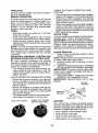
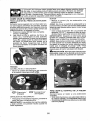
STOPPING
MOWER BLADES • To stop mower blades, move attachment
clutch control to disengaged position (r'_).
(1_'1)
Attachment
_:_ Clutch Control
Engaged
(1"_)
Attachment
ClutchControl
Dis ngaged
TO USE THROTTLE CONTROL (D)
Always operate engine at full speed (fast).
• Operating engine at less than full speed
(fast) reduces engine's operating efficiency.
• Full speed (fast) offers the best mower
performance.
GROUND DRIVE • Tostop ground ddve, depressbrake pedal
all the way down.
IMPORTANT: Forward and reverse drive
pedals return to neutral positionwhen not
depressed.
15
TO MOVE FORWARD AND BACKWARD
The direction and speed of movement is
controlled by the forward and reverse drive
pedals,
1. Start tractor and release parking
brake.
2, Slowly depress forward (K) or reverse(L)
drive pedal to begin movement. Ground
speed increases the further down the
pedal is depressed,
TO USE CRUISE CONTROL
The cruise controt feature can be used for
forward travel only.
SYSTEM CHARACTERISTICS
The cruise control should only be used
while mowing or transporting
on relatively
smooth, straight surfaces. Other conditions
such as trimming at slow speeds may cause
the cruise control to disengage, Do not use
the cruise control on slopes, rough tertian
or whUe trimmimg or turning,
- With forward drive pedal depressed to
desired speed, pull cruise control lever
(J) up and hold while lifting your foot off
the pedal, then release the lever.
To disengage the cruise control, depress the
brake pedal, tap on forward drive pedal or
push the cruise control lever down.
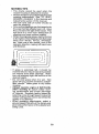
TO ADJUST
MOWER
CUTTING
The position of the attachment
determines the cutting height.
The cutting height range isapproximately1"
to 4", The heights are measured from the
groundtothe bladetip withthe engine not running.These heights are approximate andmay
vary depending upon soil conditions, height
of grass and types of grass being mowed,
° The average lawn should be cut to approximately 2-1/2" during the cool season and to over 3" during hot months.
For healthier and better looking lawns,
mow often and after moderate growth,
• For best cutting performance, grass over
6 inches in height should be mowed
twice. Make the first cut relatively high;
the second to desired height,
TO ADJUST GAUGE WHEELS
Gauge wheels are properly adjusted when
they are slightly offthe ground when mower
is at the desired cutting height in operating
position. Gauge wheels then keep the deck
Jn proper position to help prevent scalping
in most terrain conditions.
NOTE: Adjust gauge wheels with tractor on
a flat level surface,
1. Adjust mower to desired cutting height
(See 'q-O ADJUST MOWER CUTTING
HEIGHT" in this section of manual),
2. With mower in desired height ofcut position, gauge wheels should be assembled
so they are slightly offthe ground. Install
gauge wheel in appropriate hole. Tighten
securely,
3, Repeat for all, installing gauge wheel in
same adjustment hole.
HEIGHT
lift lever (A)
TO OPERATE MOWER
Your tractor is equipped with an operator
presence sensingswitch. Any attemptbythe
operator to leave the seat with the engine
runningand the attachment dutch engaged
will shut off the engine, You must remain
fully and centrarly positioned in the seat to
prevent the engine from hesitating or cutting
offwhen operating your equipment on rough,
rolling terrain or hills.
1. Select desired height of cut with attachment lift lever.
2, Start mower blades by engaging attachment clutch control.
•, Put attachment lift lever in desired cutting
height slot.
16
TO STOP MOWER BLADES • Disengage attachment clutch control.
TO OPERATE ON HILLS
,_CAUTION:
Do not operate the mower
without either the entire grass catcher, on
mowers so equipped, or the deflector shield
(S) in place.
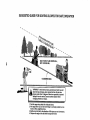
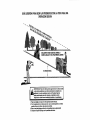
_kWARNING:
Do not drive up or down
hills with slopes greater than 15° and do not
drive across any slope, Use the slope guide
provided at the back of this manual
• Choose the slowest speed before starting
up or down hills.
• Avoid stopping or changing speed on hil!s.
• If stopping is absolutely necessary, push
brake pedal quickly to brake positionand
engage parking brake.
• Torestart movement, slowly release parking brake and brake pedal.
• Slowly depress appropriate drive pedal to
slowest setting.
• Make all turns slowly.
REVERSE OPERATION SYSTEM (ROS)
TO TRANSPORT
Your tractor is equipped with a Reverse
When pushing or towing your tractor, be
Operation System (ROS). Any attempt by
the operatortotravel inthe reverse direction sure to disengage transmission by placing
withthe attachmentclutchengaged willshut freewheel control in freewheeling position,
Free wheel control is located at the rear
off the engine unless ignition key is placed
drawbar of tractor.
in the ROS "ON" position.
• Raise attachment lift to highest position
_;L,WARNING: Backing up with the atwith attachment lift control.
tachment clutch engaged while mowing is
• Pull freewheel control out and into the slot
strongly discouraged. Turningthe ROS"ON",
and release so it is held in the disengaged
to allow reverse operation with the attachposition.
ment clutch engaged, should only be done
• Do not push or tow tractor at more than
when the operator decides it isnecessary to
two (2) MPH.
reposition the machine with the attachment
• Toreengage transmission, reverse above
engaged. Do not mow in reverse unless
procedure,
absolutely necessary.
USING THE REVERSE OPERATION
SYSTEM Only use if you are certain no children or
other bystanders willenter the mowing area:
1. Depress brake pedal all the way down.
2. With engine running, turn ignition key
counterclockwise to ROS "ON" position.
3. Look down and behind before and while
NOTE: To protect hood from damage when
backing.
transportingyourtractoron atruck or atrailer,
be sure hood isclosed and secured to tra_or,
4, Slowly depress reverse drive pedal to
start movement.
Use an appropriate means of tying hood to
tractor (rope, cord, etc.).
5. When use of the ROS is no longer
needed, turn the ignition key clockwise
TOWING CARTS AND OTHER ATTACHto engine "ON" position.
MENTS
Tow only the attachments that are recomEngine "ON" Position
ROS =ON" Position
(Normal Operating)
mendedby and comply with specifications
of the manufacturer of your tractor,Use
commonsense when towing. Too heavy
of a load, while on a slope, is dangerous.
Tires can lose tractionwith the groundand
cause you to lose control of your tractor.
e
17
SERVICE REMINDER/HOUR METER
Service reminder shows the total number
of hours the engine has run and flashesto
indicate that the engine or mower needs servicing. When service is required, the service
reminder will flash for two hours. Toservice
engine and mower, see the Maintenance
section of this manual.
NOTE: Service reminder runs when the
ignition key is in any position but "STOP".
For acurate reading, be sure key remains
in the "STOP" position when engine is not
running.
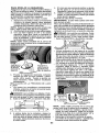
BEFORE STARTING THE ENGINE
CHECK ENGINE OIL LEVEL
The engine inyour tractor has been shipped,
from the factory, already filled with summer
weight oil.
1. Check engine oil with tractor on level
ground.
2. Remove oil fill cap!dipstick and wipe
clean, reinsert the dipstick and screw cap
tight, wait for a few seconds, remove and
read oil level. If necessary, add oil until
"FULL:' mark on dipstick is reached. Do
not overfill.
• For cold weather operation you should
change oil for easier starting (See the oil
viscosity chart in the Maintenance section
of this manual).
• Tochange engine oil, see the Maintenance
section in this manual.
, Fill fuel tank to bottom of filler neck. Do
not overfill. Use fresh, clean, regular
unleaded gasoline with a minimum of
87 octane. (Use of leaded gasoline will
increase carbon and lead oxide deposits
and reduce valve fife). Do not mix oil with
gasoline. Purchase fuel in quantities that
can be used within 30 days to assure fuel
freshness.
_IbCAUTION:
Wipe off any spilled oil or
fuel. Do not store, spill or use gasoline near
an open flame.
IMPORTANT:
When operating in temperatures below 32°F(0°C), use fresh, clean
winter grade gasoline to help insure good
cold weather starting.
18
CAUTION: Alcohol blended fuels (called
gasohol or using ethanol or methanol) can
attract moisture which leads to separation
andformation of acids during storage. Acidic
gas can damage the fuel system of an engine
while in storage. Toavoid engine problems,
the fuel system should be emptied before
storage of 30 days or longer. Drain the gas
tank, start the engine and let it run until the
fuel lines and carburetor are empty. Use
fresh fuel nextseason. See Storage Instructions for additional information. Never use
engine or carburetor cleaner products inthe
fuel tank or permanent damage may occur,
TO START ENGINE
When starting the engine for the first time or
ff the engine has run out of fuel, it will take
extra cranking time to move fuel from the
tank to the engine.
1. Be sure freewheel control isin thetransmission engaged position.
2. Sit on seat in operating position, depress
brake pedal and set parking brake.
3. Move attachment clutch to disengaged
position.
4. Move throttle control to choke position.
NOTE: Before starting, read the warm and
cold starting procedures below.
5. Insert key into ignition and turn key
clockwise to start position and release
key as soon as engine starts. Do not run
starter continuously for more than fifteen
seconds per minute. If the engine does
not start after several attempts, move
throttle control to fast position, wait a
few minutes and try again, if engine stitl
does not start, move the throttle control
back to the choke position and retry.
WARM WEATHER STARTING (50°F/10°C)
and above)
6. When engine starts, move the throttle
control to the fast position.
• The attachments and ground drive can
now be used. Ifthe engine does not accept
the load, restart the engine and allow it to
warm up for one minute using the choke
as described above.
COLD WEATHER STARTING (50°F(10°C)
and below)
6. When enginestarts, leavethrottlecontrol
in choke position until engine warms up
and begins to run roughly. Once rough
• running begins, immediately move the
throttle controlto the fast position. Engine
warm-up may take from several seconds
to several minutes (the colder the temperature, the longer the warm-up).
AUTOMATIC TRANSMISSION WARM UP
Before driving the unit in cold weather, the
transmission should be warmed up as follows:
t, Be sure the tractor is on level ground.
2. Release the parking brake and let the
brake slowly return to operating position.
3. Allow one minute for transmission to
warm up. This can be done during
the engine warm up period.
• The attachments can also be used during the engine warm-up period after the
transmission has been warmed up.
NOTE: If at a high altitude (above 3000 feet)
or in cold temperatures (below 32°F/0_C)
the carburetor fuel mixture may need to be
adjusted for best engine performance (see
"TO ADJUST CARBURETOR" intheService
and Adjustments section of this manual).
PURGE TRANSMISSION
,_CAUTION:
Neverengage ordisengage
freewheel lever while the engine is running.
Toensure proper operation and performance,
it is recommended that the transmission be
purged before operating tractor for the first
time. This procedure will remove any trapped
air inside the transmission which may have
developed during shipping of your tractor.
IMPORTANT: Should your transmission
require removal for service or replacement,
itshould be purged after reinstallation before
operating the tractor.
I.
Place tractor safely on a level surface that is clear of objects and open - with
engine off and parking brake set.
2. Disengage transmission by placing
freewheel control indisengaged position
(See "TO TRANSPORT" in this section
of manual).
3. Sitting in the tractor seat, start engine.
After theengine is running, movethrottte
control to slow position. Disengage parking brake.
,_I, CAUTION: At any time, during step 4,
there may be movement of the drive wheels.
4. Depress forward drive pedal to full forward position and hold forfive (5)seconds
and release pedal. Depress reverse drive
pedal to full reverse position and hold
for five (5) seconds and release pedal.
Repeat this procedure three (3) times.
5. Shutoff engine and set parking brake.
6. Engage transmission by placing freewheel control in engaged position (See
"TO TRANSPORT" in this section of
manual).
7, Sitting in the tractor seat, start engine.
After the engine is running, movethrottle
control to half (1/2) speed. Disengage
parking brake.
8. Drive tractor forward for approximately
five feet then backwards for five feet.
Repeat this driving procedure three
times.
Your transmission is now purged and now
ready for normal operation.
19
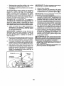
MOWING TIPS
• Tire chains cannot be used when the
mower housing is attached to tractor.
o Mower should be properlyleveled for best
mowing performance. See "TO LEVEL
MOWER HOUS]NG" in the Service and
Adjustments section of this manual,
o The left hand side of mower should be
used for trimming.
- Drive so that clippings aredischarged onto
the areathat has already been cut. Have
the cut area to the right ofthe tractor, This
will result in a more even distribution of
clippings and more uniform cutting.
o When mowing targe areas, start byturning
to the right so that clippings wilt discharge
away from shrubs, fences, driveways,
etc. After one or two rounds, mow in the
opposite direction making left hand turns
until finished.
,,_,
,,,, ,,,
J
• If grass is extremely tall, it should be
mowed twice to reduce load and possible
fire hazard from dried clippings. Make
first cut relatively high; the second to the
desired height.
• Do not mow grass when it is wet. Wet
grass wilt plug mower and leave undesirable clumps. Allow grass to dry before
mowing.
• Always operate engine at full throttle
when mowing to assure better mowing performance and proper discharge
of material Regulate ground speed by
selecting a low enough speed to give the
mower cutting performance as well as the
quality of cut desired.
• When operating attachments, select a
ground speed that will suit the terrain and
give best performance of the attachment
being used.
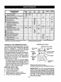
20
MA|NTENANC
'
...........
' BefORe
E
SCHEDULE
i mm,,,,,,
_VE_
_e,
a
USE
HOURS
If''
Check
v' .......v"
Pressure
Cheek Operator P_esence & ROe Systems
if
A
Check
If
C
CheektReplaf;e
foi',,,Loose
Pastene1's
Lewlnees
Check V-BsI_
H,,,,mm,,,
E
G
i
Cleat_
E_lTne
Air
....Clear Air
.,!nspeCt
V'
_
I_s
......
......
Ik_
,, ,
........................................
i_
i
OU Level
E,nglne
Chan_e
.....
i
Engine
Ol!_w_th
Oil {without
_k_
oil_lter_
"
oil _i_ter) ..........
']
..........
. VP,._
Vrl.,'z
Filter
I_i
Bore.on .........
V_
MuffisdSpark
An-ester
......................
if
EN Rep[ac.e Oil Fitter (If equipped)
,,Clean Eng!ne Cooling FEns
Plu_
SeFORe
_
_
................
V_,
Check T_'ansaxle cooling
Mower
ev_r_
s_soN STORAGE
'1_
Mower Blades
Clean Oebds Off Steering Plate
Chan.qe
too
HOUR5
.......
R Clear_BallsryandTei'minals
Che,ck
EVERY
so
HOURS
Ikf
T Lub,_eaUo_
Chart
O.....Ch_
Saue__vei
,,,Check
eveRY
=5
in,m,
Check Brake Operation
Tire
_mw
HOURS
,
.....
Re place
S _ ark
Repla_
Air Flits;" Paper Cartridge
R_place
Fuel
II_.=
!l_ =
............
, ,,
I
I_
F_lter
V'
GENERAL RECOMMENDATIONS
The warrantyon this tractor does not cover
items that have been subjected to operator
abuse or negligence. To receive full value
from the warranty, operator must maintain
tractor as instructed in this manual.
Some adjustments will need to be made periodically to properly maintain your tractor,
At least once a season, check to see ff
you should make any of the adjustments
described in the Service and Adjustments
section of this manual.
• At least once a year you should replace
the spark plug, clean or replace air filter,
and check blades and belts for wear. A
new spark plug and clean air filter assure
proper air-fuel mixture and help your engine run better and last longer.
BEFORE EACH USE
1. Check engine oil level.
2. Check brake operation.
3. Check tire pressure.
4. Check operator presence and
ROS systems for proper operation.
5. Check for loose fasteners.
LUBRICATION CHART
(_Steering Pivot Bolts
0
Zerk
Wheel
Bearing
Zerk
_Steeri_
Sector
Gear
Teeth
Zerk
FrontWheel
._adng
Zerk
_._
=
-i(_ Engine
._
(_ Mandrel
Zerks
(DGeneral Purpose Grease
@Referto Maintenance "ENGINE" Section.
IMPORTANT: Do not oil or greasethe pivot
points which have special nylon bearings,
Viscous lubricants will attract dust and dirt
that will shorten the life ofthe self-lubricating
bearings, ifyou feelthey must be lubricated,
use only a dry, powdered graphite type
lubricant sparingly.
21
TRACTOR
Always
observesafety rules when performing any maintenance.
BRAKE OPERATION
if tractor requires more than five (5) feet to
stop at highest speed in highest gear on a
level, dry concrete or paved surface, then
brake must be serviced. (See "TO CHECK
BRAKE" in the Service and Adjustments
section of this manual).
TIRES
• Maintain proper air pressure in all tires
(See PSI on tires).
- Keep tires free of gasoline, oil, or insect
control chemicals which can harm rubber.
• Avoid stumps, stones, deep ruts, sharp
objects and other hazards that may cause
tire damage.
NOTE: To seal tire punctures and prevent
flat tires due to slow leaks, tire sealant may
be purchased from your local parts dealer.
Tire sealant also prevents tire dry rot and
corrosion.
OPERATOR PRESENCE SYSTEM AND
REVERSE OPERATION SYSTEM (ROS)
Be sure operator presence and reverse
operation systems are working properly. If
your tractor does not function as described,
repair the problem immediately.
• The engine should not start unless the
brake pedal is fully depressed, and the
attachment clutch control is in the disengaged position.
CHECK OPERATOR PRESENCE SYSTEM
• When the engine is running, any attempt
by the operator to leave the seat without
first setting the parking brake should shut
off the engine.
° When the engine is running and the attachment clutch is engaged, any attempt
by the operator to leave the seat should
shut off the engine.
• The attachmentclutch should neveroperate unless the operator is in the seat.
CHECK REVERSE OPERATION (ROS)
SYSTEM
• When the engine is running withtheignition
switch inthe engine "ON" position and the
attachment clutch engaged, any attempt
by the operator to shift into reverse should
shut offthe engine,
• When the engine is runningwith theignition
switch in the ROS "ON" position and the
attachment clutch engaged, any attempt
bythe operator to shift into reverse should
NOT shut off the engine.
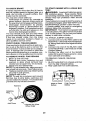
BLADE CARE
For best resultsmower blades must besharp.
Replace worn, bent or damaged blades.
• ,CAUTION: Useonly a replacement blade
approved bythe manufacturer of your tractor.
Using a blade not approved by the manufacturer of your tractor is hazardous, could
damage your tractor and void your warranty.
BLADE REMOVAL
1. Raise mowerto highest positionto allow
access to blades.
NOTE: Protect your hands with gloves and/
or wrap blade with heavy cloth.
2. Remove blade bolt by turning counterclockwise.
3. Install newbladewith stamped"THIS SIDE
UP" facing deck and mandrel assembly.
IMPORTANT: To ensure proper assembly,
center hole in blade must align with star on
mandrel assembly.
4. Install and tighten blade bolt securely
(45-55 Ft. Lbs. torque!65-75 Nm).
IMPORTANT: Special blade bolt is heat
treated.
Mandrel
Assernbly
Blade Bolt_-_:_
Center Hole
ROS "ON" Position
Engine "ON" Position
(Normal Operating)
_ €_-,"__-F J-/
(SPec ial)__.__;_S
_
BATTERY
Your tractor has a battery chargingsystem
whichissufficient for normal use. However,
periodiccharging ofthe battery with an automotive chargerwill extend itslife.
• Keep battery and terminals clean.
• Keep battery bolts tight.
,, Keep small vent holes open.
• Recharge at 6-10 amperes for 1 hour,
22
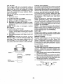
TO CHANGE ENGINE OIL
Determine temperature range expected
before oil change. All oil must meet AP!
service classification SG-SL.
NOTE: The odginal equipment battery on
your tractor is maintenance free, Do not
attempt to open or remove caps or covers.
Adding or checking level of electrolyte is
not necessary.
TO CLEAN BATTERY AND TERMINALS
Corrosion and dirt on the battery and terminals can cause the battery to "leak" power.
1, Remove terminal guard.
2. Disconnect BLACK battery cable first
then RED battery cable and remove
battery from tractor.
3. Rinsethebatterywith plainwateranddry.
4. Clean terminals and battery cable ends
with wire brush until bright.
5. Coat termina!s with grease or petroleum
jelly.
6. Reinstall battery (See "REPLACING
BATTERY" in the SERVICE AND ADJUSTMENTS section of this manual).
• Be sure tractor is on level surface.
• Oil wi!l drain more freely when warm.
° Catch oil in a suitable container.
1. Remove oil fill cap!dipstick. Be careful
notto allow dirtto enter the engine when
changing oil.
2. Slide oil drain extension fromthe docking
position on the engine blower housing
and extend outward from engine.
Docking
Position
V-BELTS
Check V-belts for deterioration andwearafter
1O0hours of operation and replace if necessary. The belts are not adjustable, Replace
belts if they begin to slip from wear.
ENGINE
LUBRICATION
Only use high quality detergent oil rated with
API service classification SG-SL. Selectthe
oil's SAE viscosity grade according to your
expected operating temperature.
Oil Drain
Extension
3. To open, twist cap counter-clockwise
4. After oi! is drained completely, replace
cap and twist clockwise until it stops.
5. Re-attach oil drain extension to engine
blower housing.
6. Refillenginewith oilthrough oilfitl dipstick
tube. Pour slowly. Do not overfill. For approximate capacity see "PRODUCT SPECIFICATIONS" section of this manual.
7. Use gauge on oil fill cap/dipstick for
checking level. For accurate reading,
tighten dipstick cap securely onto the
tube before removing dipstick. Keep oil
at "FULE line on dipstick. Tighten cap
onto the tube securely when finished.
NOTE: Although multi-viscosity oils (5W30,
10W30 etc.) improve starting in cold weather,
they will result in increased oil consumption
when used above 32°F/0°C. Check your
engine oil level more frequently to avoid possible engine damage from running low on oil,
Change the oil after every 50 hours of operation or at !east once a year if the tractor is
not used for 50 hours in one year.
Checkthe crankcase oillevel before starting
the engine and after each eight (8) hours
of operation. Tighten oil fi!l cap/dipstick
securely each time you check the oil level.
ENGINE OIL FILTER
Replace the engine oil filter every season or
every other oil change if the tractor is used
more than 100 hours in one year.
23
CLEAN AIR SCREEN
Air screen must be kept free of dirt and chaff
to prevent engine damage from overheating,
Clean with a wire brush or compressed airto
remove dirt and stubborn dried gum fibers.
CLEAN AIR INTAKE/COOLING AREAS
To ensure proper cooling, make sure the
grass screen, cooling fins, and other external surfaces of the engine are kept clean
at all times.
Every 100 hours of operation (more often
under extremely dust,7, dirty conditions),
removethe blower housing and other cooling
shrouds. Clean the cooling fins and external
surfaces as necessary. Make surethe cooling
shrouds are reinstalled.
NOTE: Operatingthe engine with ablocked
grass screen, dirty or plugged cooling fins,
and/or cooling shrouds removed will cause
engine damage due to overheating.
MUFFLER
Inspect and replace corroded muffler and
spark arrester (if equipped) as it could create
a fire hazard and/or damage.
SPARK PLUG(S)
Replace spark plug(s) at the beginning of
each mowing season or after every 100
hours of operation, whichever occurs first,
Spark plug type and gap setting are shown
in "PRODUCT SPECIFICATIONS" section
of this manual.
AIR FILTER
Your engine will not run properly using a
dirty air filter. Clean the foam pre-cleaner
• after every 25 hours of operation or every
season. Service paper cartridge every 100
hours of operation or every season, whichever occurs first,
Service air cleaner more often under dusty
conditions.
1. Remove cover.
TO SERVICE PRE-CLEANER
2. Wash it in liquid detergent and water.
3, Squeeze it dry in a clean cloth.
4. Saturate it in engine oil. Wrap it in clean,
absorbent cloth and squeeze to remove
excess oil.
NOTE: If very dirty or damaged, replace
pre.cleaner,
TO SERVICE CARTRIDGE
1. Clean cartridge by tapping gently on flat
surface, ifverydirtyordamaged, replace
cartridge.
2. Reinstall precleaner cartridge, cover and
secure,
IMPORTANT: Petroleum solvents, such as
kerosene, are not to be used to clean the
cartridge. They may cause deterioration of
the cartridge. Do not oil cartridge. Do not
use pressurized airto clean or dry cartridge.
Knobs\_
IN-LINE FUEL FILTER
The fuel filter should be replaced once each
season. If fuel filter becomes clogged, obstructing fuelflowto carburetor, replacement
is required.
1. With engine cool, remove filter and plug
fuel line sections.
2. PIace newfuel filter in position infuel line
with arrow pointing towards carburetor.
3. Be sure there are no fuel line leaks and
clamps are properly positioned.
4. Immediately wipe up any spilled gasoline.
Cover
i_Cartridg
Foam
Pre-Oleaner
/
e
..............
_--]
k__._ji,'
FuelFilter -_-_--__--J
24
CLEANING
• Clean engine, battery, seat, finish, etc.
of all foreign matter.
° Clean debris from steering plate. Debris
can restrict clutch/brake pedal shaft
movement, causing belt slip and toss of
drive.
,_ CAUTION: Avoid all pinch points and
movable parts
/Clutchlbrake pedal
Clean ._
IMPORTANT: Tug hose ensuring connection is secure.
5. Turn the water on.
Steering
6.
=_ _
Steerin System,Dash,
Fenderand Mowerl_ot Shown
°
Keep finished surfaces and wheefs
free of all gasoline, oil, etc.
• Protect painted surfaces with automotive type wax.
We do not recommend using a garden hose
or pressure washer to clean your tractor
unless the engine and transmission are
covered to keep water out. Water in engine
or transmission will shorten the useful life of
your tractor. Use compressed air or a leaf
blower to remove grass, leaves and trash
from tractor and mower.
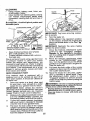
DECK WASHOUT PORT
Your tractor's deck is equipped with a
washout port on its surface as part of its
deck wash system. It should be utilized after each use.
1. Drive the tractor to a level, clear spot
on your lawn, near enough to a water
spigot for your garden hose to reach.
IMPORTANT: Make certain the tractor's
discharge chute isdirected AWAYfrom your
house, garage, parked cars, etc. Remove
bagger chute or mulch cover if attached.
2. Make surethe attachment clutch control
is in the "DISENGAGED" position, set
the parking brake, and stop the engine.
3.
4.
Thread the nozzle adapter !packaged
with your tractor's Operator s Manual)
onto the end of your garden hose.
Pull back the lock collar of the nozzle
adapter and push the adapter onto the
deck washout port at the left end of the
mower deck. Release the lockcollar to
lock the adapter on the nozzle.
25
While sitting in the operator's position
on the tractor, re,start the engine and
place the throttle lever In the Fast ",_
position.
IMPORTANT: Recheck the area making
certain the area is clear.
7. Move the tractor's attachment clutch
control to the "-=ngag ed" position.
Remain in the operator's position
with the cuttingdeck engaged until the
deck is cleaned.
8. Move the tractor's attachment clutch
control to the "DISENGAGED" position. Turn the ignition key to the STOP
position to turn the tractor's engine off.
Turn the water off.
9. Pull back the lock collar of the nozzle
adapter to disconnect the adapter lrom
the nozzle washout port.
10. Move the tractor to a dry area, preferably a concrete or paved area. Place
the attachment c_utch contro( in the
"Engaged" position to remove excess
water and to help dry before putting the
tractor away.
A_kWARNING: A brokenor missingwashout
fitting couldexposeyouor others to thrown
objectsfrom contactwith the blade.
• Replacebrokenormissingwashoutfitting
immediately,priorto usingmoweragain.
- Plug any holes in mower with bolts and
locknuts.
_
..
4.
5.
6.
ARNING: TO AVOID SERIOUS INJURY, BEFORE PERFORMING ANY SERVIC'E OR
ADJUSTMENTS:
Depress
clutchtbrake
pedal
fully and set parking
brake.
Place attachment
clutch
in "DISENGAGED"
position.
Turn ignition key to "STOP" and remove key,
Make sure the blades and all moving parts have completely stopped.
Disconnect spark plug wire from spark plug and place wire where it cannot come
in contact with plug.
]
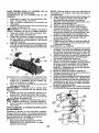
TO REMOVE MOWER
1. Place attachment clutch in "DISENGAGED" position.
2. Lower attachment lift to lowest position.
3. Disengage belttension rod (K)from lock
bracket (L).
_,CAUTION: Rod is spring loaded. Have a
tight grip on rod and release slowly.
4. Remove mower belt from electric clutch
pulley (M).
5. Disconnect front link (E) from mower remove retainer spring and washer.
6, Go to either side of mower and disconnect mower suspension arm (A) from
chassis and rear lift link (C) from rear
mower bracket (D) - remove retainer
springs and washers,
26
7. Go to other sideof mower and disconnect
_kthe suspension arm and rear lift link,
CAUTION: After rear liftlinks are disconnected, the attachment lift lever willbe spring
loaded. Have a tight grip on lift lever when
changing position of the lever.
8. From right side of mower, disconnect
anti-sway bar (S) from right rear mower
bracket (D) - remove retainer spring and
washer and pull mower toward you until
the bar falls from the hole in bracket.
9. Turn tractor steering wheel to the left as
far as it will go.
10. Slide mower out from under right side of
tractor.
TO INSTALL
MOWER
Follow procedure described
MOWER" in the Assembly
manual.
in"TO INSTALL
section of this
TO LEVEL MOWER
Make sure tires are properly inflated to the
PSI shown ontires. Iftires are over or under
inflated, it may affect the appearance of your
lawn and lead you to think the mower is not
adjusted properly.
VISUAL SfDE-TO-SIDE ADJUSTM ENT
1, With all tires properly inflated and if your
lawn appears unevenly cut, determine
which side of mower is cutting lower.
NOTE: As desired, you can raise the low
side of mower or lower the high side.
2. Go to side of mower you wish to adjust.
3. With a 3/4" or adjustable wrench, turn
lift link adjustment nut (A) to the ]eft to
Iower the mower, or, to the right to raise
the mower.
Turn'nut righl
t0:iaise mower
4. If adjustment is necessary, see steps 2
and 3 in Visual Adjustment instructions
above.
5. Recheck measurements, adjust if necessary until both sides are equal.
FRONT-TO-BACK ADJUSTMENT
IMPORTANT: Deck must be level sideto-side.
Toobtain the best cutting results, the mower
blades should be adjusted so the front tip is
I/8"to 1/2" lower than the rear tip when the
41_oweris in its highest position.
CAUTION: Blades are sharp. Protect
your hands with gloves and/or wrap blade
with heavy cloth.
o Raise mower to highest position.
o Position any blade so the tip is pointing
straight forward. Measure distance (B) to
the ground atfront and reartip ofthe blade.
Turn nut left
to lower mower
NOTE: Each full turn of adjustment nut will
change mower height about 3/16".
4. Test your adjustment by mowing some
uncut grass and visually checking the
appearance. Readjust, if necessary, until
you are satisfied with the results,
PRECISION SIDE÷TO-SIDEADJUSTMENT
1. With all tires properly inflated, parktractor
on level ground or driveway.
CAUTION: Blades are sharp. Protect
your hands with gloves and/or wrap blade
with heavy cloth.
2. Raise mower to itshighest position.
3. At both sides of mower, position blade at
side and measure the distance (A) from
bottom edge of blade to the ground, The
distanceshould bethesameon bothsides.
At
'
'
tLW.1A 27
• If front tip of blade is not 1t8" to 1t2" lower
than the rear tip, go to the front of tractor.
• With an 11/16" or adjustable wrench,
loosen jam nut A several turns to clear
adjustment nut B.
• With a 3/4" or adjustable wrench, turn
front link adjustment nut (B) clockwise
(Itighten) to raise the front of mower, or,
counterclockwise (loosen) to lower the
front mower.
Tighten adjust nut
B to raise mower
, Loosen adjust
nut B t0':10wer
mower
Loosenjam nut A first
NOTE: Each full turn ofthe adjustment nut
wilt change mower height about 1,!8",
• Recheck measurements, adjust if necessary until front tip of blade is 1/8" to 1/2"
lower than the rear tip.
• Hold adjustment nutin position with wrench
and tighten jam nut securely against adjustment nut.
TO REPLACE
MOWER
TO REPLACE MOTION DRIVE BELT
Park the tractor on level surface. Engage
parking brake. For assistance, there is a
belt installation guide decal on bottom side
of left footrest.
DRIVE BELT
MOWER DRIVE BELT REMOVAL
1. Parktractor on a level surface. Engage
parking brake.
2. Lower attachment lift lever to its lowest
position.
3, Disengagebelttension rod (K) from]ock
bracket (L).
AUTION: Belttension rod is spring loaded. Haveaflrm grip on rod and releaseslowly.
4. Remove screws (P) from R.H. and L,H.
mandrel covers and remove covers (Q).
5. Remove anydirtor grass clippings which
may have accumulated around mandrels
and entire upper deck surface.
6. Remove belt from electric clutch pulley
(M), both mandrel pulleys (R) and all idler
pulleys (S).
BELT REMOVAL 1. Remove mower (See "TO REMOVE
MOWER" in this section of manual).
NOTE" Observe entire motion drive belt and
position of all belt guides and keepers.
2. Remove beltfrom stationaryidler (A) and
clutching idler (B).
3. Remove belt from centerspan idler (C),
4. Puff belt slack toward rear of tractor.
Carefully remove bett upwards from
transmission input pulley and over cooling fan blades (D).
5, Remove belt downward from engine
pulley (E).
6. Slide belt toward rear of tractor, off the
steering plate (F)and removefromtractor.
BELT INSTALLATION 1. Install new belt from tractor rear to front,
over the steering plate (F) and above
clutch brake pedal shaft (G).
2. Pull belt toward front of tractor and roll
belt onto engine pulley (E).
3. Pull belt toward rear of tractor. Carefully
work belt down around transmission
cooling fan and onto the input pulley (D).
Be sure belt is inside the belt keeper,
4. Install belt on centerspan idler (C).
5, Install belt through stationary idler (A)
and clutching idler (B).
6. Make sure belt is in all pulley grooves
and inside all belt guides and keepers.
7. Install mower (See "TO INSTALL MOWER" in this section of manual),
MOWER DRIVE BELT INSTALLATION
1. Install belt around both mandrel pulleys
(R) and around idlerpulleys (S) asshown.
2. Installbelt onto electric clutch pulley (M),
IMPORTANT: Check belt for proper routing
in all mower pulley grooves.
3. Reassemble R.H. and L,H. mandrel covers (Q). Securely tighten all screws.
4. Engage belt tension rod (K) on locking
_ bracket (L),
CAUTION: Belt tension rod isspring loaded. Haveatight grip on rod and engage slowly,
5. Raise attachment lift lever to highest
position.
28
TO CHECK BRAKE
If tractor requires more than five (5) feet to
stop at highest speed in highest gear on a
level, dry concrete or paved surface, then
brake must be serviced.
You may also check brake by:
I. Park tractor on a level, dry concrete or
paved surface, depress brake pedal all
the way down and engage parking brake.
2. Disengage transmission
by placing
freewheel control in "transmission disengaged" position. Pullfreewheel control
out and into the slot and release so it is
held in the disengaged position,
The rear wheels must lock and skid when
you tryto manually push the tractor forward.
If the rear wheels rotate, then the brake
needs to be serviced. Contact a Sears or
other qualified service center.
FRONT WHEEL TOE-IN/CAMBER
Your new tractor front wheel toe-in and camber is set at the factory and is normal, The
frontwheeltoe-in and camber are not adjustable. If damage has occurred to affect the
factory setfront wheel toe-in or camber, contact a Sears or other qualified service center.
TO REMOVE WHEEL FOR REPAIRS
1. Block up axle securely.
2, Remove axle cover, retaining ring and
washers to allow wheel removal (rear
wheels have a square key - Do not lose).
3. Repair tire and reassemble.
NOTE: On rearwheels only: align grooves in
rear wheel hub and axle. Insert square key.
4. Replacewashers and snap retaining ring
securely in axle groove.
5. Replace axle cover.
NOTE: To seal tire punctures and prevent
flat tires due to slow leaks, purchase and
use tire sealantfrom Sears. Tire sealant also
prevents tire dry rot and corrosion,
TO START ENGINE WITH A WEAK BATTERY
_WARNING:
Lead-acid batteries generate explosive gases, Keep sparks, flame
and smokingmaterials awayfrom batteries.
Atways wear eye protection when around
batteries.
Ifyour battery istooweakto startthe engine, it
should be recharged. (See "BATTERY" inthe
MAINTENANCE section of this manual).
if "jumper cables" are used for emergency
starting, follow this procedure:
IMPORTANT: Your tractor is equipped with
a 12voitsystem. The otherveh[cle mustalso
be a 12 volt system. Do not use your tractor
battery to start other vehicles.
TO ATTACH JUMPER CABLES
1. Connectone end ofthe RED cable tothe
POSITIVE (+) terminal of each battery(AB), taking care notto shortagainsttractor
chassis.
2. Connect one end of the BLACK cable
to the NEGATIVE (-) terminal (C) of fully
charged battery.
3. Connect the other end of the BLACK
cable (D) to good chassis ground, away
from fuel tank and battery.
TO REMOVE CABLES, REVERSE
ORDER
1. BLACK cable firstfrom chassis and then
from the fully charged battery.
2. RED cable fast from both batteries.
Washers
Retaining
Ring \\\\
I
Axle Cover
_Square
Key (Rear
WheelOnly)
29
Weak or Dead
Fully Charged
Battery
Battery
REPLACING BATTERY
TO REMOVE HOOD AND GRILL
ASSEMBLY
1. Raise hood.
2. Unsnap headlight wire connector.
3. Stand in front of tractor. Grasp hood at
sides, tilt toward engine and lift off of
tractor.
4. When replacing hood, be sureto reconnect the headlightwire connector.
n_aWARNING: Do not short battery termiy allowing awrench orany otherobject
to contact both terminals at the same time.
Before connecting battery, remove metal
bracelets, wristwatch bands, rings, etc.
Positive terminal must be connected first to
prevent sparking from accidental grounding.
1. Lift hood to raised position,
2. Remove terminal cover.
3. Disconnect BLACK battery cable then
RED battery cable and carefully remove
battery from tractor.
4. Install new battery with terminals insame
position as old battery.
5. Reinstall terminal cover.
6, First connect RED battery cable to positive (+) battery terminal with bolt and nut
as shown. Tighten securely.
7, Connect BLACK grounding cable to
negative (-) battery terminal with remaining bolt and nut, Tighten securely
8. Close hood.
H°iedadlightWire
r
TRANSMISSION
REMOVAL/REPLACEMENT
Should yourtransmissionrequire removal for
service or replacement,it should be purged
after reinstallation and beforeoperatingthe
tractor. See "PURGE TRANSMISSION" in
the Operation section of this manual.
TO REPLACE HEADLIGHT BULB
1. Raise hood,
2. Remove bulb holder from the hole in the
backside of the gri]l.
3. Replace bulb in holder and install bulb
holder securely back into the hole in the
backside of the grill.
4. Close hood.
INTERLOCKS AND RELAYS
Loose or damaged wiring may cause your
tractor to runpoorly, stoprunning, orprevent
it from starting.
• Check wiring,
TO REPLACE FUSE
Replace with 30 amp automotive-type plugin fuse. The fuse holderis located behind
the dash.
ENGINE
TO ADJUST THROTTLE CONTROL
CABLE
The throttle control has been preset at
the factory and adjustment should not be
necessary Check adjustment as described
below before loosening cable. If adjustment
is necessary, see engine manual.
TO ADJUST CHOKE CONTROL
The choke control has been preset at
the factory and adjustment should not be
necessary, If adjustment is necessary, see
engine manual.
TO ADJUST CARBURETOR
Yourcarburetor has beenpreset atthe factory
and adjustment should not be necessary.
However, minor adjustment may be required
to compensate for differences in fuel, temperature, altitude or load. If the engine does
need adjustment, see engine manual.
3O
immediately prepare your tractor for storage
at the end of the season or if the tractor will
not be used for 30 days or more.
_ WARNING: Never store the tractor with
gasoline in the tank inside a building where
fumes may reach an open flame or spark.
Allow the engine to cool before storing in
any enclosure.
TRACTOR
Remove mower from tractor for winter
storage. When mower is to be storedfor a
period of time, clean it thoroughly, remove
all dirt, grease, leaves, etc. Storein a ctean,
dry area.
1. Clean entire tractor (See "CLEANING"
in the Maintenance section of this
manual).
2. Inspect and replace belts, if necessary
(See belt replacement instructions inthe
Service and Adjustments section of this
manual).
3. Lubricate as shown in the Maintenance
section of this manual.
4. Be sure that all nuts, bolts and screws
are securely fastened. Inspect moving
parts for damage, breakage and wear.
Replace if necessary.
5. Touch up all rusted or chipped paint
surfaces; sand lightly before painting.
BATTERY
- Fully charge the battery for storage.
• After a period of time in storage, battery
may require recharging.
• Tohelp prevent corrosion and power leakage during long periods ofstorage, battery
cables should be disconnected and battery cleaned thoroughly (see "TO CLEAN
BATTERY AND TERMINALS" in the
Maintenance section of this manual).
- After cleaning, leave cables disconnected
and place cables where they can not come
in contact with battery terminals.
• If battery is removed from tractor for
storage, do not store battery directly on
concrete or damp surfaces.
ENGINE
FUEL SYSTEM
IMPORTANT: It is important to prevent
gum depositsfrom forming in essentialfuel
system partssuch as carburetor,fuel hose,
ortankduringstorage,Also, alcoholblended
fuels (called gasohol or using ethanol or
methanol) can attract moisturewhich leads
to separation andformation of acids during
storage, Acidic gas can damage the rue[
system of an engine while in storage.
, Empty the fuel tank by startingthe engine
and letting it run until the fuel lines and
carburetor are empty.
• Never use engine or carburetor cleaner
products in the fuel tank or permanent
damage may occur.
o Use fresh fuel next season.
NOTE: Fuel stabilizer is an acceptable alternative in minimizing the formation of rue!
gumdepositsduring storage. Add stabilizer
to gasoline infuel tank or storage container.
Always foUowthe mixratio found on stabilizer
container. Run engine at least 10 minutes
after addingstabilizertoaliowthe stabilizerto
reachthe carburetor. Do not emptythe gas
tank and carburetor if using fuel stabilizer.
ENGINE OIL
Drain oil (with engine warm) and replace
with clean engine oil. (See "ENGINE" in the
Maintenance section of this manual).
CYLINDER(S)
1. Remove spark plug(s).
2. Pour one ounce of oil through spark plug
hole(s) into cylinder(s).
3. Turn ignition key to "START" position for
a few seconds to distribute oil.
4. Replace with new spark plug(s).
OTHER
o Do not store gasoline from one season to
another.
• Replaceyour gasoline can ifyour can starts
to rust. Rust and/or dirt in your gasoline
wi[I cause problems.
• If possible, store your tractor indoors and
coverit to give protection from dustand dirt.
• Cover your tractor with a suitable protective cover that does not retain moisture.
Do notuse plastic. Plastic cannot breathe
which allowscondensation to form and will
cause your tractor to rust.
IMPORTANT:
Never cover tractor while
engine and exhaust areas are still warm.
31
TROUBLESHOOTING CHART:
See appropriate section in manual unless directed to Sears service center
PROBLEM
CAUSE
Will not start
CORRECTION
Out of fuel.
1
Engine not "CHOKED"
properly.
2.
Engine flooded.
F,Ifueltonk'i
.......
See "TO START ENGINE" in
Operation section,
Wait several minutes before
attempting to start.
4
Bad spark plug.
5
Dirty air filter,
5
Clean/replace
6
!4
Replace spark plug,
air filter.
Dirty fuel filter,
6
Replace fuel filter.
7
Water in fuel,
7
Empty fuel tank and carburetor,
refill tank with fresh gasoline and
replace fuel filter,
i8
Loose or damaged wiring,
8
Check all wiring.
Carburetor
9
See "To Adjust Carburetor" in
Service and Adjustments section
10
Con!act a Sears or other qualified
servfce center.
9
10
out of adjustment.
Engine valves out of adjustment.
.......
,,, ,,,_,
Hard to start
1
Dirty air filter.
1
Clean/replace
2
Bad spark plug,
2
Replace spark plug,
3
Weak or dead battery.
3
Recharge
4
Dirty fuel filter,
4
Replace fuel filter.
5
Stale or dirty fuel
5
Empty fuel tank and refill tank witl"
fresh, clean gasoline,
6
air filter.
or replace battery.
Loose or damaged wiring,
6
Check all wiring,
7
Carburetor
7
See "To Adjust Carburetor" in
Service and Adjustments section.
8
Engine valves out of adjustment,
1
Brake pedal not depressed,
1
Depress brake pedal,
2
Attachment
2
Disengage attachment
3
Weak or dead battery,
3
Recharge or replace battery,
4
Blown fuse,
4
Replace fuse.
5
Corroded battery terminals.
5
Clean battery terminals.
6
Loose or damaged wiring.
6
Check all wiring.
7
Faulty ignition switch,
7
Check/replace
ignition switch.
8
Faulty solenoid or starter.
8
Check/replace
solenoid
9
Faulty operator presence
switch(es).
9
Contact a Sears or other qualified
service center.
out of adjustment,
' Contact a Sears or other qualified
service center,
,,, ,,,
Engine will not
turn over
clutch is engaged.
32
clutch.
or starter.
TROUBLESHOOTING CHART:
See appropriate section in manual unless directed to Sears service center
PROBLEM
CORRECTION
CAUSE
,,
Engine
clicks
will not start
but
Loss of power
Weak or dead battery.
1 i Recharge or replace battery.
2
Corroded battery terminals.
2
Clean battery terminals.
3
Loose or damaged wiring.
3
Check all wiring.
4
Faulty solenoid or starter,
4
ChecWreplace
1
Cutting too much grass!too fast.
;1
Raise cutting height!reduce
speed.
2
Throttle in "CHOKE"
Adfust throttle control.
vibration
, ,
,,,,,
solenoid
or starter.
pos_ion,
i2
Build-up of grass, leaves and
trash under mower.
3
Clean underside
housing.
4
Dirty air filter.
4
Clean/replace
5
Low oil level/dirty oil,
5
Check o[I level/change oil.
6
Faulty spark plug,
6
Clean and regap or change spark
plug,
7
Dirty fuel filter.
7
Replace fuel filter,
8
Stale or dirty fuel.
8
Empty fuel tank and refill tank with
fresh, clean gasoline.
9
Water in fuel,
t0
Spark plug wire loose.
10
Connect and tighten spark plug
wire.
11
Dirty engine air screen!fins.
11
Clean engine air screen/fins,
12
Dirty/clogged
12
Clearffrep_ace muffler.
13
Loose or damaged wiring,
13
Check aI] wiring.
14
Carburetor
14
See "To Adjust Carburetor" in
Service and Adjustments section,
15
Engine valves out of adjustment.
15
Contact a Sears or other qualified
service center,
J3
Excessive
,,,,
;
of mower
air filter.
Empty fuel tank and carburetor,
refilI tank with fresh gasoline and
replace fuel filter.
muffler.
out of adjustment.
1
Worn, bent or loose blade.
1
Replace blade. Tighten
2
Bent blade mandrel.
2
Contact a Sears or other
blade bolt.
qualified service center.
3
Loose/damaged
part(s).
3
Tighten loose part(s).
Replace damaged parts.
1
run when operator
leaves
seat with
attachment
clutch
Faulty operator-safety presence
control system.
engaged
33
1
Check widng, switches and
connections. If not corrected,
contact a Sears or other
TROUBLESHOOTING CHART:
See appropriate section in manual unless directed to Sears sewice center
PROBLEM
CAUSE
CORRECTION
, ,,,,,, ,,
Poor
cut
Worn, bent or loose blade.
1
Repi';'ce"b]ade,
Tighten blade boli
2
Mower deck not level.
2
Level mower deck,
3
Buildup of grass, leaves, and
trash under mower.
3
Clean underside
housing.
Bent blade mandrel
4
Contact a Sears or other
qualified service center.
- uneven
cutting
of mower
Clean around mandrels
open vent holes.
Clogged mower deck vent from
build-up of grass, leaves, and
trash around mandrels.
to
,,,,,,
Mower blades will
not rotate
1
Obstruction
2
Womtdamaged
3
1
Remove obstruction.
2
Replace mower drive belt.
Frozen idler pulley.
3
Replace idler pulley.
4
Frozen blade mandrel.
4
Contact a Bears or other qualified
service Center.
1
Engine speed too slow.
2
Travel speed too fast.
2
Shift to slower speed.
3
Wet grass.
3
Allow grass to dry before mowing
Mower deck not level.
4
Level mower deck.
5
Low]uneven
5
Check tires for proper PSI.
6
Worn, bent or loose blade.
6
Replace/sharpen
blade bolt.
7
Buildup of grass, leaves and
trash under mower.
8
Mower
9
Blades improperly
Poor grass
discharge
4
_
Headlight(s) not
working
(if so equipped)
in clutch mechanism.
mower
drive belt
,1
tire air pressure.
Place throttle control in '=FAST"
position.
blade. Tighten
Clean underside
housing.
drive belt worn.
installed.
of mower
8
Replace mower drive belt.
9
Reinstall blades sharp edge down.
10
Improper blades
11
11 Clean around mandrels to
Clogged mower deck vent holes
from buildup of grass, leaves, and
open vent holes.
trash around mandrels.
used.
10' Replace with blades listed in
this manual.
1
Ught switch is "OFF".
1
"Iijm light switch "ON".
2
Bulb(s) or tamp(s) burned out.
2
Replace bulb(s) or lamp(s),
3
Faulty light switch.
_3
4
Loose or damaged wiring.
4
5
Blown fuse.
5
34
Check/replace
light switch.
=Check wiring and connections.
Replace fuse.
TROUBLESHOOTING CHART:
See appropriate section in manual unless directed to Sears service center
PROBLEM
CAUSE
CORRECTION
,,,,,,,u,_
atte wil,not
1
.......
Bad battery cell(s).
1
Replace battery.
Poor cable connections,
2
ChecK/clean all connections.
3
Faulty regulator (if so equipped).
3
Replace regulator,
4
Faulty alternator,
4
Replace alternator.
Freewheel control in "disengaged"
position.
1
Place freewheel control in
=engaged" position.
Motion drive belt worn, damaged,
or broken.
2
Replace motion drive belt.
charge
, ,,,,,
Loss of drive
1
' Air trapped in transmission
shipment or servicing.
,,,,
Engine"backfires"
when turning
engine "OFF"
Engine dies when
tractor is shifted
into reverse
1
during
:3
Purge transmission.
,,,,,,,...........
Engine throttle control not eel 1
between half and full speed (fgst)
position before stopping engine.
Reverse
operation
system
(ROe)
is not "ON" while mower or other
attachment is engaged.
Move throttle control between
half and full speed (fast) position
before stopping engine.
Turn ignition key to ROS "ON"
position. See Operation section.
! You[Ifindtheanswerand more on managemyhome.com
i
" Find this
and aLL your other product
!i
" Get answers
iI
. Get a personalized
:
• Find _nformation
manuals
online.
from our team of home experts.
maintenance
plan for your home.
and tools to help with home projects.
b_oughtto gou by Sears
35
- forfree!
SUGGESTED
GUIDE
FOR SIGHTING
SLOPES
ONLY RIDE UP AND
NOT ACROSS HILL
03
DOWN
FOR SAFE OPERATION
HILL,
15 DEGREES MAX.
_
down
the face
elopes,
never
across
the face.
not mow
ARNING:
To of
avoid
serious
injury,
operate
yourDo
tractor
up and
, slopes greater than 15 degrees. Make turns gradually to prevent
tipping or loss of control. Exercise extreme caution when
changing direction on slopes.
1. Fold this page along dotted line indicated above.
2. Hold page before you so that its left edge is vertically parallel to a tree
trunk or other upright structure.
3. Sight across the fold in the direction of hill slope you want to measure.
4. Compare the angle of the fold with the slope of the hill.
Garant{a..........................................................
Reglas de Seguridad ......................................
Especificaciones deI Producto ........................
Montaje]Pre Operaci6n ...................................
Operaci6n .......................................................
Mantenimiento ................................................
37
38
41
42
48
56
Programa de Mantenimiento .......................... 56
Servicio y Ajustes ........................................... 61
Almacenamiento ............................................. 66
Identificaci6n de Problemas ........................... 67
Servicio Sears .................................. Contratapa
Garant{a para equipos tractores Craftsman
GARANTiA COMPLETA DE CRAFTSMAN
PeR DOS At-JOS desde la fecha de compra, todas tas partes no sustituibles de este equipo tractor estdn
garantizadas contra cualquier defecto de material o mane de obra, Una parte no sustituible defectuosa
recJbird reparaci6n o reemplazo gratuito en casa sila reparaci6n as imposible.
PeR C]NCO AI_,IOS desde ta fecha de compra, el bastidor y et eje de]antero de este equipo tractor estdn
garantizados contra cualquier defecto de material o mane de obra. Un bastidor o eje delantero defectuoso
recibir_ reparaciSn o reemplazo gratuito en casa sila reparaci6n es imposible.
DURANTE 90 DiAS desde ]a fecha de compra, la bater[a (una parte eustituible) de este equipo tractor
est,. garantizada contra cualquier defecto de material o mane de obra (nuestra prueba comprueba qua no
contendr_ carga). Una bateffa defectuosa recibir& un reemplazo gratuito en casa.
GARANT{A
UMITADA
DE PeR
VIDA ADICIONAL
en el EJE DELANTERO
DE HIERRO
COLADO
(sl
est& provisto)
DURANTE EL TIEMPO EN QUE SE USE per el propietario original despu_s clef quinto aSo a partir de la
fecha de compra, et eje delantero de hierro colado (st est_ provisto) de este equipo tractos est_ garantizado
oontra cua]quier defecto de material o mane de obra. Con el comprobante de compra, un eje delantero de
hierro colado recibir& un reemplazo gratuito en casa.
SERMI;IO
DE GARANTiA
Para conocer los detalles de Ia cobertura de garant{a para obtener
I{ame al 1-800-659-5917
6 vis_te el sitio web: www. craftsman.corn
una reparaciSn o reemplazo
gratuito,
En redes los cases antedores, si el reemplazo es imposible, el equipo tracior ser_ sustituido sin cargo con
el mismo modelo o uno equivalente.
Toda Ia cobertura de garanffa anterior ser& nula sieste equipo tractor se utiliza alguna vez para brindar
servicios comerciales o si se a[quila aotra persona.
Eeta garant{a cubre I_NfOAMENTE defectos de material y mane de obra, La cobertura de garantia NO incluye:
• Partes sustituibles (excepto la hater{a) qua se puedan desgastar per el use normal dentro del per|ode de
garant{a incluso, pare sin limitarse a, cuchilIas, bujfas, filtros de aire, correas y filtros de aceite,
• Servicios de mantenimiento est_ndar, cambios de aceite o afinaciones.
•
•
Reemplazo o reparaciSn de neum_ticos
espinas, tocones o viddos.
Reemplazo o reparaci6n de neum_ticos
mantenimiento incorrectos.
per pinchazos
causados
o ruedas per desgaste
per objetos
extemos
normal, accidentes
•
come clavos,
o per operaci6n
o
Reparaciones necesarias per abuse del operador incluso, pare sin limitarse a, dafios causados per
remolcar objetos que superen la capacidad del equipo tractor, chocar contra objetos que doblen el
bastidor, el ensamble del eje o el cig_eSal o sobrepasar [a velocidad del motor.
• Reparaciones necesarias per negligencia det operader, incluso (pero gin ]imitarse a ella) 6aSos el_ctr[cos
y mec_nicos causados per el almacenamiento
incorrecto, per no usar el grade y la cantidad correctos de
aceite de motor, per no mantener del muelle libra de residues inflamables o per no mantener e[ equipo
tractor de acuerdo con las instrucciones qua contiene el manual del operador.
° Limpieza o reparaciones
del motor (sistema de combustible)
cuando se determina
que se us5
combustible contaminado y oxidado (sarro). En general, el combustible debe usarse dentro de los 30
dias posteriores a su compra.
• Deterioro y desgasie normal de los acabados exteriores o sustituci6n de rStulos de productos.
Esta garant|a le otorga detaches [egales especfficos, y usted tambi_n puede tener otros detaches qua
varian de un estado a otro.
Sears Brands Management Corporation, Hoffman Estates, IL 60179
37
_PELIGRO:
Esta Maquina cortadora es capaz de amputar las manosy los pies y de |anzar
objetos, si no se observan las instrucciones de seguridad siguientes se pueden producir
lesiones graves o la muerte.
• No maneje Ia m&quina si no tiene la trampa
_DVERTENCIA:
Siempre desconecte el alampara c_sped completa, la canaleta de descarga
brede ta bujfa y p6ngalo donde no pueda entrar
u otros dispositivos de seguridad en su lugar
en contacto con la bujfa, para evitar el arranque
yen funcionamiento.
por accidente, durante Ia preparaciSn, el trans• Ra[entizar antes de girar.
porte, el ajuste o cuando sa hacen reparaciones,
° Nunca dejar una m&quina encendida sin vigi_0_DVERTENCIA: Noavancecuestaabajo a punlancia. Apagar siempre las cuchillas, porter el
to muerto ya que podriaperderel con_'oldeltractor,
freno de estacionamiento, parar el motor, y
quitar las Ilaves antes de bajar.
_kADVERTENCIA:
Remolque solamente los
accesorios recomendados y conformes a las
• Desenganche las hojas cuando no est6 cortancaracteristicas indicadas por el fabricante de su
do c_sped. Apague el motor y espere hasta que
tractor. Tenga cuidado y prudencia al utilizar el
todas ]as partes se detengan por completo antes de timpiar la m&quina, retirar la trampa para
tractor. Cuando se ancuentreen un declive, oper
utilizandoexclusivamenta la velocidad m_.sbaja.
c_sped o destapar Ia canaleta de descarga.
En caso de un declive una carga excesiva po•Hacer funcionar la m&quina s6Io con Ia luz del
drfa resultar peligrosa. Los neum&ticospueden
alia o luz artificial buena.
perder la tracci6n con el suelo y hacede perder
• No hacer funcionar Ia m&quina estando bajo
et control de su tractor.
los efectos de alcoho] o droga.
_I_ADVERTENCIA: Eltubo de escape del motor,
• Porter atenci6n al tr&fico cuando se opera
cerca de caUes o se cruzan.
algunos de sus constituyentas y algunos componentes del vehicu]o contienen o desprenden
, Poner la m&xima atenci6n aI cargar o descarproductos quimicos conocidos en el Estado de
gar Ia m&quina en una caravans o cami6n.
California como causa de c&ncer y defectos al
° Llevar siempre gafas de protecci6n cuando se
nacimiento u otros daSos reproductivos.
hace funcionar la m&quina.
_DVERTENCIA:
Los homes, terminales y ac• Los datos indican que los operadores a partir
de los 60 aSos est&n afectados por un gran
cesorios relativos de la bateria contienen plomo
porcentajede heridas relativas a Ia conduccibn
o compuestos de plomo, productos qulmicos
del cortac@sped. Estos operadores tendrian
conocidosen el Estado de California como causa
que evaluar su habilidad de hacer funcionar
de cdncer y defectos al nacimiento u otrosda_os
el cortac@sped de modo Io bastante seguro
reproductivos. Lavar las manos despuds de
para proteger a si mismos y a otras personas
manipularlos,
de heridas graves.
I. FUNClONAMIENTO
GENERAL
• Seguir ]as recomendaciones de] fabricante
•Leer, entenderyseguirtodaslasinstrucciones
para los pesos y contrapesos de las ruedas.
sobre la m&quina yen el manual antes de
• Mantener Ia m_.quina libre de hierba, hojas u
empezar.
otros escombros que pueden tocar el tubo de
• No poner las manos o los pies cerca de partes
escapeipartes del motor calientes y quemarse.
giratorias o debajo de la m&quina, mantener
No permitir que el puente del cortac_sped
siempre limpia la abertura de descarga,
cargue hojas u otros residuos que pueden
• Permitir el funcionamiento de Ia m&quina sSIo
causar acumulaciones. Limpiar toda salpica°
dura de aceite o carburante antes de hacer
a adultos que tengan familiaddad con ]as
instrucciones.
operaciones sobre ]a mdquina o guardarla.
Dejarla enfriar antes de guardarla.
• Limpiar el &tea de objetos como piedras,
juguetes, cables, etc. que pueden set recogiII. FUNCIONAMIENTO
EN PENDIENTES
dos y disparados con las cuchillas.
Las pendientes son el mayor factor de accidentes
• Asegurarse de que el _rea est_ libre de otras
relativos a Ia p_rdida de control y vuelco, que
personas antes de ponerla en marcha. Parar
pueden causar severas heridas o muerte. El funla rn&quina si alguien entra en el &rea.
cionamiento en pendientes requiere una atenci6n
• Nunca Ilevar pasajeros.
extra. Si no es posiblehacer marcha atr&s en una
° No cortar marcha atr&s al no ser absolupendiente o site sientes incomodo,no Ia cortes.
tamente necesado. Mirar siempre abajo y
* Cortar hacia ardba y abajo de una pendiente,
delante mientras se procede atr&s.
no de modo horizontal.
• Nunca dirigir el material descargado hacia na, Poner atenciones a los hoyos, las ra[ces, los
die. Evitar descargar material contra paredes
bultos, Ias piedras u otros objetos escondidos,
u obstrucciones. El material podria rebotar
El terreno irregular puede voJcar la m&quina.
hacia el operador. Parar las cuchillas cuando
La hierba alta puede esconder 0bst_culos.
se pasan superficies de grava.
38
• Esooger una ve[ecidad de rnarcha baja de
mode que nosea necesario pararse o carnbiar
estando en una pendiente.
• No cortar la hierba mojada. Las ruedas pueden
perder tracci6n.
Poner siempre una marcha cuando se est&
en pendientes. No poner en punto rnuerto e ir
cuesta abajo.
• Evttar arrancar, pararse o girar en una pendienre. Si las ruedas pierden traccibn, desconectar
tas cuchillas y preceder despacio cuesta abajo
en la pendiente.
, Mantener todo los movimientos en las pendientes lentos y gradual. No hater cambios
repentinos de velocidad o direcci6n, ya que
pueden causar et escape de la rn__quina.
• Poner la m_<ima atenciSn cuando la m__quina
funciona con captadores de hierba u otros
dispositivos enganchados; pueden afectar ta
estabilidad de la rn&quina. No usar en pendientes ernpinados.
• No intentar estabilizar [a m&quina poniendo el
pie en el terreno.
• No cortar cerca de bajadas, cunetas y oriltas.
Las rn&quina puede volcarse improvisarnente
si una rueda est& en el horde o se hunde.
•
Tenet el m&xirno cuidado cuando se acerca
a cantos ciegos, arbustos, &rboles u otros
objetos que pueden impedir la vista de niSos.
IV, REMOLQUE
, Remolcar s6Io c_onuna m&quina que tenga un
gancho diseSado para rernoEcar.Enganchar el
equipo o rerno]car s61o en el punto dispuesto
al efecto.
• Seguir las recomendaciones del productor con
respecto a los lirnitesdet equipo per rernolcar
y el remolque en pendientes.
• Nunoa perrnitir que nihos u otras personas
est6n dentro del equipo per remolcar.
• En pendientes, e! peso del equipo rerno]cado
puede causar la p_rdida de tracci6n y ta p(_rd[da de control.
• Viaiar despacio y dejar mAs distancia para
frenar.
V, SERVICIO
MANIPULACION SEGURA DE LA GASOLINA
Para evitar heridas personales o dahos alas
cosas, poner el rn_lxirno cuidado a {a hera de
rnanipular la gasolina. La gasolina es extrema_
rnente inflarnab[e y los vapores son explosives.
• Apagar todos los cigarrillos, cigarros, pipas y
otras fuentes de igniciSn.
• Usars61ocontenedoresparagasolinaaprobados.
• Nunca quitar el tapbn de Ia gaso[ina o aSadir
carburante con et motor en marcha, dejar
enfriar el motor antes de] abastecirniento de
la gasolina.
• Nunca abastecer la m,iquina al interior de un
local.
° Nunca guardar Ia m&quina o el contenedor
del carburante deride haya una llama abierta,
chispas o una luz piloto come un calentador
de agua u otros dispositivos.
• Nunca Ilenar los contenedores al interior de
un vehIculo o en una caravana o carni6n
recubiertos con un forte de plAstico. Colocar
siernpre los contenedores en el terreno lejos
del vehlculo cuando se est_ llenando.
III. NIl;lOS
_IbADVERTENC|A:
LOS NII_IOS PUEDEN
SUFRIR DANES CON EL use DE ESTE EQUIPO. La Academia Estadounidense de Pediatria
(American Academy of Pediatrics) recornienda
que sSlo se perrnita a nihos con una edad minima de 12 ahes manejar m&quinas cortac_sped
manuales, y aI menos de 16 aSos para manejar
tractores cortac_sped.
Si el operador no pone atencibn a la presencia
de los nihos pueden ocurrir accidentes tr_.gicos.
Los nifios a menudo est&n atraidos per la m,iquinay las actividad de cortar. No dar per hecho
de que los nihos se queden adonde estaban la
=31tirnavez que los vistes,
• Mantener los ni5os fuera del &tea de corte y
vigilados per un adulto responsable que no sea
el operador.
• Estar alerta y apagar la rn&quina si un niSos
entra en e[ &rea.
• Antes y durante la rnarcha atrAs, mirar adelante
y abajo para ver si hay nihos pequeSos.
- Nunca Ilevar nihos, inc[uso s{hay las cuchillas
apagadas. Podrfan caer y herirse seriamente
o interferir con el funcionarniento seguro de la
rn&quina, los nihos que se han Ilevado precedenternente pueden aparecer de pronto en el
_.reade corte per otro paseo y set atropellados
o tumbados per Iam&qu{na,
o Nunca dejar que los nihos manipulen la rn_quina,
• Quitar ef equipo de gas del carni6n o caravana
y abastecerlo en el terreno. Si no es posible,
abastecer dicho equipocon un contenedor pert&til, rn,is bien que de un surtidor de gasoIina.
• Mantener la boquilla a contacto del borde
del dep6site de carburante o la abertura del
contenedor durante toda [a operaoibn de
abasteoirniento. No utilizar un dispositivo con
boquilla cerrada-abierta.
• Si se v[erte carburante sobre la ropa, carnbiarse la ropa inmediatarnente.
• Nunca l]enar el dep6sito rnAs de Io debido,
Velvet a co[ocar el tapSn del gas y carrar de
mode firrne.
39
OPERACIONES DE SERVICIO GENERALES
• Nunca hacer funcionar la rn_.quina en un &rea
cerrada.
• Mantener todas las tuercas y pernos apretados
para asegurarse de que trabaja en condiciones
seguras.
• Nunca modificar Ios dispositivos de seguridad.
Controlar su correcto funeionarniento regularmente.
- Mantener Ia m&quina libre de hierba, hojas
u otros residuos acumulados. Limpiar las
salpicaduras de aceite o carburante y quitar
cualquier cosa mojada con carburante. Dejar
que la m&quina se enfrfe antes de guardarla.
• Controlar el funcionarnlento del freno frecuento
emente. Ajustar y hacer las operaciones de
mantenirniento cuando eso sea necesario.
• Mantener y sustituir las etiquetas de seguridad
e instrucciSn, cuando sea necesario.
• Asegurarse de que el &rea est_ libre de otras
personas antes de ponerla en rnarcha, para la
m&quina si alguien entra en el &rea.
• Nunca Ilevar pasajeros.
• No cortar rnareha atr&s al no ser absolutarnente
necesario. Mirar siernpre abajo y delante
rnientras se procede atr&s.
• Nunca I]evar nifios, inclusosi hay las cuchillas
apagadas. Podrian caer y herirse seriarnente
o interferir con el funcionamiento seguro de (a
m&quina, los niSos que se han Ilevado precedenternente pueden aparecer de pronto en el
&rea de corte por otro paseo y ser atropellados
o tumbados por la m&quina.
• Mantener los nitros fuera del &rea de corte y
vigilados por un adulto responsable que no sea
el operador.
4O
• Si se golpea un objeto ajeno, hay que pararse
e inspeccionar la m__quina. Reparar, si es
necesario, antes de volver a poneren marcha,
• Nunca hacer ningen ajuste o reparaci6n con
el motor en funci6n.
. Verifique los componentes de la trarnpa para
c(_sped y ia canaleta de descarga con frecuenciay sustituya con repuestos recomendados
pot el fabricante cuando sea necesar(o.
• ).as euchillas del cortae_sped son afiladas.
Envolver la cuchU(a, ponerse guantes y poner
ta m&xima atenci6n cuando se haeen operaciones en elias.
• Estar alerta y apagar la rn&quina si un nifios
entra en el &rea.
• Antes y durante larnarcha atr&s, rnirar adelante
y abajo para ver si hay niSos pequeSos.
° Cortar hacia arriba y abajo de una pendiente
(I5 ° M&x), no de rnodo horizontal.
• Escoger una velocidad de marcha baja de
modo que no sea necesario pararse o earnbiar
estando en una pendiente.
• Evitar arrancar, pararse o girar en una pendiente. Si Ias ruedas pierden tracci6n, desconectar
las cuchillas y procederdespac)o cuesta abajo
en Ia pendiente.
° Si la rn_=quina se para mientras va cuesta
ardba, desconectar las cuchillas, poner Ia
rnarcha atr&s y Jrhacia atr&s despaeio.
• No girar estando en pendientes si no es necesar(o, y luego girar despacio y gradualrnente
euesta abajo, si es posible.
- AI cargar o descargar larn&quina, no sobrepase
el &ngulo rn_t×irnorecomendado de I5 °.
En el estado de California, la ley exige Io anterior
(Secci6n 4442 del =California Public Resources
Code"). Otros estados pueden contar con otras
Ieyes parecidas. Las leyes federales se aplican
en Fatierras federales. Su centro de Servicio m,_s
cercano tiene disponible amortiguadores de chispas para el silenciador.(Vea Ia secci6n de Partes
de Repuesto en el manual Ingles del dueSo.)
ESPECIFICACIONES DEL PRODUCTO
Capacidad y -Iipo 3.0 Galones (11,35 L)
Regular Sin Piomo
de gasolina:
SAE 30 (Sobre 32°F/0°C)
Tipo de Aceite:
SAE 5W30
_PI: SG-SL)
(Debajo 32°F/0°C)
Capacidad de
Aceite:
Con filtro: 64 oz.(t ,9 L)
Sin fiitro: 60 oz.(1,7 L)
Bujia:
Champion QCt2YC
(Abertura: .040"/t,02mm)
Delante:
5,2/8,4
Velocidad de
Recorrido
(Mph/Kph):
Marcha Atrds:
2,9/4,7
Sistema de Carga: 16 Amps @ 3600RPM
Bateria:
Amp/Hr:
Min. CCA:
Case Size:
28
230
UI R
Torsi6n del Perno
de Ia Cuchilta:
45-55 FtoLbs. (62-75 Nm)
FELICITACIONES por lacompra de su tractor.Ha
sidodiseSado, planit_cadoy fabdcado para darle la
mejor confiabilidady el mejor rendimiento posible.
En el caso de que se encuentre con cualquier
problema que no pueda solucionar f&cilmente,
haga el favor de ponerse en contacto con un
centro de servicioSears o con un otto centro de
servicio cualificado.Cuenta con representantes
bien capacitados y competentes y con las herramientas adecuadas para darle servicio o para
reparar este tractor.
Haga el favor de leer y de guardar este manual
Estas instruc-ciones ]e permitirdnmontar y mantenet su unidad en forma adecuada. Siempre
observe Ias "REGLAS DE SEGURtDAD."
RESPONSABILIDADES
DEL CUENTE
o Lea y observe las reglas de seguridad.
* Siga un programa regular de mantenimiento,
cuidado y uso de su tractor.
. Siga Ias instruccionesdescritas en las secciones "Mantenimiento" y '_,lmacenamiento"
de este manual
.
Utilice prendas de seguridad adecuadas al
manejar Ia m&quina, incluidos (como minimo)
calzado de seguridad,galas protectorasy protecci6n auditiva. No utilice pantalones cortos
yio calzado abierto cuando corte la hierba.
- Informe siempre a alguien de que se dispone
•a cortar la hierba en el exterior.
_t_DVERTENCIA:
Este tractor viene equipado
con un motorde combusti6ninterna y no se debe
usar sobre, o cetca, de un terreno no desarrollado
cubierto de bosques, de arbustos o de c_sped,
o menos que el sistema de escape del motor
venga equipado con un amortiguador de chispas
que cumpla con Ias leyes locales o estatales (si
existen). Si se usa un amortiguador de chispas,
e] operador debe mantenerlo en condiciones de
trabajo eficientes,
ACUERDOS
DE, PROTECClON
PARA
LA REPARACION
Congratu]aciones
por su buena compra. Su
nuevo producto Craftsman@ estd disefiado y
fabricado para funcionar de modo fiable por
muchos arias. Pero como todos los productos,
puede neces[tar alguna reparaci6n de tanto en
tanto. En este caso tenet un Acuerdo de Protecci6n para Ia Reparaci6n puede hacedes ahorrar
dinero y fastidios.
Compre ahora unAcuerdo de Protecci6n para la
Reparaci6n y prot@gese de molestias y gastos
inesperados.
Un Acuerdo inc[uyelos puntos siguientes:
• Ser¢icio experto de nuestros 12.000 especialistas profesionales en la reparaci6n.
• Servicio ilimitado sin cargo alguno para
las partes y ta mano de obra sobre todas las
reparaciones garantizadas.
• Sustituci6n
del producto
si su producto
garantizado no puede ser arreglado.
• Descuento de110% sobre el precio corriente
det servicio y de las partes relativas ai servicio
no cubiertas por el acuerdo; tambi_n el 10%
menos sobre el precio corriente de un control
de mantenimiento preventivo.
• Ayuda rdp|da pot tel_fono- soporte te]ef6nico por parte de un repreeentante Sears sobre
productos que requieren un arre91o en casa, y
adem_ts una programaciSn sobre los arreglos
m_s convenientes.
Cuando se ha comprado el Acuerdo, basta con
una llamada telef6nica para programar el servicio.
Puede Ilamar cuando quiera, dta y noche o fijar
en Ifnea una cita para obtener el servicio. Sears
tiene m_.s de 12.000 especialistas profesionales
en la reparaci6n, que tienen acceso a m&s de
4.5 miliones de partes y accesorios de calidad.
Este es el tipo de profesionaiidad con que puede
contar para ayudar a alargar la vida del producto que acaba de comprar, por muchos aSos.
iCompre hoy su Acuerdo de Protecci6n para la
Reparaci6n]
Se aplican algunas limitaciones y exclusiones,
Para conocer los precios y tener rods Informaci6n, Ilame al 1-800-827-6655.
41
SERVICIO
DE INSTALACION
SEARS
Para la instalaci6n profesional Sears de apara_
tos de casa, puertas de garaje, calentadores de
agua y otros importantes artfculos para la casa,
en U.S.A llamar a
1-800-4-MY-HOME®
Segadora
Rueda Delantera De La Segadora
(2) C°nj unt°
_
de es|abones
de levantamiento
(5) i-3/16"
Arandela
traseros
(1) Abrazadera
peque_o
=
\\
j_
(1) Perno
@
(1) 1-1/4"
Arandela
%
_'_
de retenci6n
_
\\.
(1) Es]abones
"_\
de levantamiento
\_,
delanteros
"_
__
___J
(1) Rueda
(11 3/8.16"
Tuerca
(5) Abrazadera
grande de retenci6n
.... i,,,,
, ,,,H,,
Hoja de pendiente
Si Los Tiene
Llaves
(1 t Barra
Antioscilacidn
(1) Abrazadera
peque_o
(1) 3/4"
Arandela
(2) Llaves
de retencibn
42
Su tractor nuevo ha s]domontado en la f&bdca con la excepci6n de aquellas partes que no se han montado por razones de envio. Para asegurarse que su tractor funcione an forma adecuada y segura todas
]aspartes y los articulos de ferreteria que se monten tienen que set apretados en forma segura. Use 1as
herramientas correct&%segt_n sea necesado, para asegurarse de que est_n apretados en forma segura.
3.
HERRAMIENTAS
NECESARIAS
PARA
EL MONTAJE
Un juego de Ilaves de tubo facilitar,_ el montaje.
A continuacibn se enumeran los tamaSos de ]as
I[aves est_ndar.
(2) Llaves de 7/16"
Cuchitlo
(1) Llaves de 1/2"
Medidor de presi6n
(1) Llave de 3/4"
Pinzas
(1) Montura de 3/4 pu]g. con mando de trinquete
(1) Llaves de 1/2"
Lintema
Cuando en este manual se mencionan los t6rminos "mano derecha" o "manoizquierda" se refierea
cuando usted se encuentra en la posic]Sn de operaci6n (sentado/a detrds del volante de direcci6n).
Desconecte la pa[anea para trabar e! asiento
en la posici6n.
AVISO: Ahora puede rodar su tractor fuera
de la corredera. Siga las siguientes instrucciones para remover el tractor de la corredera.
_lb ADVERTENCIA: Antes de empezar, leer,
entender y seguir todas las instruccionespresentes en ta secci6n Operaciones de este manual.
Asegurarse que el tractor est_ en un _.rea bien
ventiJada. Asegurarse que la zona de]ante de1
tractor est_ libre de otras personas y objetos.
PARA REMOVER
EL TRACTOR
DE LA
CAJA DE CARTON
DESEMPAQUE LA CAJA DE CARTON
•
Remueva todas las partes sueltas que est_n
accesibles, y las cajas de partes, de la caja
de cart6n grande.
* Cortar alo largo de Ias][neas de puntosentodos
los cuatro paneles de cart6n. Remover los paneles de cierre y aplanar los pane]eslaterales.
•
Remueva ]a segadora y los materiales del
embalage.
Revise si hay partes sueltas adicionales o
cart6n y remu_valas.
ANTES DE REMOVER EL TRACTOR DE
LA CORREDERA
PAPA HACER RODAR ELTRACTOR FUERA DE
LACORREDERA(Vealaseccidn dela operacibn
para la Iocalidad y la funci6n de los controles)
•
Levante Ia palanca de levantamiento del
accesofio a su posici6n m&s alta.
SueJte el freno de estacionamiento presionando el pedal del embragueifreno.
•
Ponga el control de la rueda Iibre en la
posici6n de giro libre para desenganchar la
transmis[6n. (Vea "PARA TRANSPORTAR °
en ]asecciSn de Operaci6n de este manual).
•
Haga rodar el tractor hacia delante fuera de
[a corredera.
VERIFtQUE LA BATERIA
1. Levante deI capota a _aposici6n levantada.
AVISO: Siesta bater[a esta utilizadadespu_s del
mes y afio [ndicado sobre ]a etiqueta (Ia etiqueta
que se encuentra entre los terminales), cargue la
baterTa pot un minimo de una hera a 6-10 amps.
(Vea "BATERIA" en la secci6n de Mantenimento
de este manual).
•
Para instale la bateria, y cable de Ia
baterta, realice el procedim_ento descrito en
"REEMPLAZAR LA BATERI_' de] capltulo de
Servicio y Ajustes de este manual.
Continuar con las siguientes instrucciones.
INSTALE LA SEGADORA
1. ACC]ONE LA PALANCA DEL FRENO DE
ESTACIONAMIENTO Y LA PALANCA DE LEVANTAMIENTO DELACCESORIO INFERIOR
=
=
leta
AJUSTE EL ASIENTO
1. Si_ntese sobre el asiento.
2. Levante la palancadel ajuste (A) hacia arriba
y mueva el asiento hasta que aJcance una
posicibnc6modaque le permita presionar comp]etamentesobre el pedal dal embrague/freno.
43
Prasioneel pedal de embragueifreno comp]etamente hasta abajo y mant6ngalo apretado.
Tire y mantenga Ia palanca del freno de estacionamiento hacia arriba, libere la presi6n del
pedal de embrague/freno y, ]uego, suelte la
palancadeifreno de estacionamiento. El pedal
debe permanecer en posici6n de frenado.
Aseg_rese de que el freno de estacionamiento
mantendrd asegurado el tractor.
a
PRECAUCION: La pa]ancade [evantamiento
est&accionada per resorte Sost_ngalafirmemente
apretada, b&jela lentamente y eng_nchela en la
posici6n m&s baja Lapalancadelevantamientose
encuentra en el Iado izquierdo de [a defensa
3
Gire el volante completamente hacia [a
izquierda y ubique Ia cortadera de c_sped
en el lade derecho del tractor con el b]indaje
deflector (Q) a la derecha
Palanca De
Levantamiento
2
GIRE EL VOLANTE HACIA LA IZQUIERDA
Y UBIQUE LA CORTADORA DE CESPED
EN SU LUGAR
Parte Delantera
Motor
ARME LA RUEDA CALtBRADORA DELANTERA (W) EN LA PARTE DELANTERA DE
LA CORTADORA DE CESPED
Parte Trasera
4,
Q
Blindaje Deflector
DESLICE LA CORTADORA DE CESPED
DEBAJO DEL TRACTOR
Ueve la correa hacia adetante y verifique que
su trayectoria sea correcta en redes lossurcos
de la polea de la cortadora de c_sped
H Escuadra De La Cortadora De C_sped
Delantera
W. Rueda Calibradora
Delantera
X Perno Con Resalto
Y Arandela De 1-1/4
Z
Tuerca De Seguridad
De 3/8-16
NOTA: Aseg_rese de que los brazes de susp
ensi6n lateral de lacortadora de c6sped (A) est@n
orientados hacia adelante antes de deslizar Ia
cortadora de c_sped debajo del tractor
•
Deslice la cortadora de c_sped debajo del
tractor basra que se encuentre centrada
debajo deI tractor
®
A Brazes De Suspensi6n Lateral
De La Cortadora De C@sped
B Resorte De Retenci6n
C Eslabones De Levantamiento Traseros
D Escuadra Trasera Derecha De La Cortadora
De C_sped
E Conjunto De Eslabones De Levantamiento
Delanteros
E Escuadra De Suspensi6n Delantera
H Escuadra De La Cortadora De C@sped
Delantera
L Escuadra Trasera Izquierda De La
Cor_.adoraDe C_sped
K Varilla Tensora De La Correa
L Escuadra De Bloqueo
M, Polea Del Embrague Del Motor
Q Blindaje Deflector
S Barra Antibalanceo
W Rueda Cailbradera Delantera
44
Haga oscilar el extremo con la arandela
integrada de la barra antibalanceo (S) hacia
la escuadra de la plataforma de la cortadora
de c6spsd en el Iado derecho de Ia cortadora.
Inserte el extremo con [a arandela integrada
de la barra en el agujero de la escuadra
trasera de Ia cortadora de c_sped (D). Mueva
la cortadora de cL=spedsegQn sea necesario
para insertar el extremo con la arandela
integrada de fa barra en la escuadra trasera
de ta cortadora de ce_sped(D).
Asegure con una arandela pequeSa y un resorte de retenci6n pequeSo, como se ilustra.
A. Brazos
DeSus_ensi6n
Lateral
DeLa
Cortadora
DeC_sped
..Q. 8tindaie Deflector,
5.
SI LA TIENE, INSTALE LA BARRA
ANTIBALANOEO (S)
BARRA
Extremo
En 90°
ANTIBALANCEO
(S)
Hacia La Plataforma
De La Cortadora
De C_sped
_
D. Escuadra Trasera Derecha De La
Oortadora De C_spad
S. Barra Antibalanceo
T.
Extremo Con
Arandela Integrada
Desde el lado derecho de la cortadora de
c_sped, inserts pdmero el extremo en 90 °de Ia
barra antibalanceo (S) dentro deI agujero de la
escuadra de transeje (T), ubicado cerca de Ia
ruedatrasera izquierda adelante del transeje.
NOTA: Puede resultar 6til usar una ILnterna;
INSTALE LOS BRAZOS DE SUSPE.NS_6N
LATERAL DE LA CORTADORA DE CESPED
(A) EN EL CHASIS
Ubique el agujero delantero de1 brazo de
suspensi6n lateral (A) sobre la chaveta en la
parte exteriordel chasJsdel tractor y asegure
con una arandela grande y un resorte de
retencibn grande (B).
RepP_ en el lado opuesto del tractor.
Escuadra De Transeje (_
Ubicada Entre Las Ruedas
B. Resorte De Retenci6n
D. Escuadra Tras-Era Derecha De ILa
Cortadora De C_sped
7.
NOTA: Dependiendo del rnodelo, ta escuadra (_
puede ser diferente de la qua se ilustra, pero e]
agujero para la barra antibalanceo estar& en la
misma posici6n/ubicaci6n.
45
INSTALE LOS ESLABONES DE LEVANTAMIENTO TRASEROS ((3)
[nserte el extremo de varilla del eslab6n de
levantarniento trasero (C) dentro det agujero
(U) en el brazo desuspensi6nde leje de levantamiento del tractor y haga oscilar el eslab6n
hacia abajo hacia la cortadora de c_sped.
°
•
Levante la esquina trasera de Ia cortadora de
c_spedyubique laranuraen elconjunto de eslabones sobrelachavetaen]aescuadratrasera
de lacortadora (D); asegure con unaarandeta
grande y un resorte de retenci6n grande.
Repita en el Iado opuesto del tractor.
•
•
Mu_vase hasta eJlado izquferdo de [a cortadora e inserte un resorte de retenci6n grande
(G) a trav_s del agujero del eslab6n delantero
(E) detr&s de la escuadra de suspensi6n
delantera (F).
lnserte el otro extremo del eslab6n (E) en el
agujera de laescuadraderecha de la cortadora
de c_sped (H) y asegure con una arandela y
un resorte de retenci6n peque_o (J).
NOTA: Requiere levantar la ptetaforma.
9. 1NSTALELA CORREA EN LA POLEA DEL
EMBRAGUE DEL MOTOR (M)
•
Desenganche ]a varilla tensora de la correa
(K) de la escuadra de bloqueo (L).
Instale la correa en la polea de! embrague
deI motor (M)
C.
D.
'
U,
8.
°
°
Eslabones De Levantamfento Traseros
Escuadra Trasera Derecha De La
Cortadora De C_sped
Agujero
INSTALE EL ESLABON DELANTERO (E)
Gire et volante basra ubicar las ruedas derechas en posici6n de avance.
Desde la parte delantera del tractor, inserte el
extremo de varilla del eslab6n delantero (E)a
trav_s deI agujero delantero de la escuadra
de suspensi6n delantera deJtractor (F).
Ubicaci6n
Del Eslab6n
Delantero
/"
'
_
M. Polea DeI
Embrague
Del Motor
IMPORTANTE: Verifique qua la trayectoria de
la correa sea correcta en todos ]as surcos de la
polea de la cortadora de c_sped y debajo de ]as
cubiertas de mandril
I _'_
_
Enganche ia varilla tensora de la correa (K)
en la escuadra de bloqueo (L).
_i, PRECAUC|ON: la varilla tensora de fa correa
est& accionada par resorte. Sostenga la varilla
firmemente apretada y eng&nchela lentamente.
•
Eleve la palanca de levantamiento deI accesorio hasta la posicibn m_,xima.
•
Si es necesario, ajuste las rueditas det calibre
antes de porter en funcionamiento la cortadora, coma se ilustra en el capitu]o de Manejo
de este manual.
PARA REEMPLAZAR LA CORREA
DE LA SEGADORA
Realice el procedimiento descrito en "PARA
REEMPLAZAR LA CORREA DE LA CUCHtLLA
DE LA SEGADOR_' deI capftulo de Servicio y
Ajustes de este manual
E
G.
H.
J.
M.
Escuadra De SuspensiSn Delantera
Resorte De Retenci6n Grande
EscuadraDeLa CortadoraDe C_spedDelantera
Resorte De Retenci6n PequeSo
Polea Del Embrague Dei Motor
46
REVISION
DE LA PRESION
DE LAS
LLANTAS
Las liantas en su unidad fueron infladas dernasiado en la f&brica por razones de envfo. La
presi6n de fas Ilantas correctas es importante
para obtener el major rendimiento en el corte.
• Reduzca _apresiSndelos neum_.ticos a ]a PSI
que se indica en estos.
JLISTA
DE REVISION
Antes de operar y de disfrutar de su tractor nuevo,
le deseamos que reciba el mejor rendimiento yla
mayor satisfaccion de este producto de calidad.
Haga el favor de revisar Ia Iista a continuacion:
J Se han comp]etadotodas las instrucciones de
montaje.
J No quedan partes sueltas en Ia caja de
cart6n.
J La bateda est& preparada y cargada en forma
adecuada,
J EI asiento ha sido ajustado en forma c6moda
y apretado en forma segura.
,/Todas las Ilantas han sido infladas en forma
adecuada, (Para fines de envio, las Ilantas se
inflarondemasiado en la fdbrica.)
JAsegdrese
que eI conjunto segador est_
nivelado en forma adecuada, de lado a lado y
desde adelante hacia atrds, para obtener los
mejores resultados en el corte. (Las Ilantas
tisnen qua estar infladas en forma adecuada
para la nivelaci6n.)
_/Revise tas correas de impulsi6n y de la
segadora. AsegQrese qua recorran el paso
adecuado alrededor de tas poleas y dentro de
todos los fijadores de las correas.
J" Revise el alambrado. Fijese que todas las
conexiones todavia est_n seguras y que los
alambres est_n sujetos en forma adecuada.
J" Antes de conducir et tractor, asegQrese que
el control de rueda libra este en]a posici6n
de "transmisibn enganchada" (Vea "PARA
TRANSPORTAR" en la secci6n de la Operaci6n de este manual).
AI mismo tiempo qua aprende a como usar su
tractor, preste atencion extra a los puntos de
importancia qua se presentan a continuacion:
REVISION
DE LA NIVELACION
DEL
CON JUNTO
Para obtener los mejores resultados en el corte,
la caja de la segadora tiene que estar nivelada
en la forma adecuada. Vea "PARA NIVELAR
LA CAJA DE LA SEGADOP_' en la seccibn de
Servicio y Ajustes de este manual.
REVISION DE LA POSIClON ADECUADA
DE TODAS LAS CORREAS
Yea las figuras que aparecen para cambiar las
correas de imputsiSn de la cuchilla de la sega_
doray de movimiento en Ia seccidn de Servicio y
Ajustes de este manual. Verifique que [as correas
sigan su paso correcto.
REVISION DEL SISTEMA DE FRENOS
Una vez que usted haya aprendido a manejar su
tractor, verifique qua el franc funcione correctamente. Ver "PARA VERIFICAR SI FUNCIONA
BIEN EL FRENO" en el capitulo de servicio y
ajustes de este manual.
/El aceite def motor tiene qua Itegar al niveI
adecuado.
,f El estanque de combustible tiene que estar
Ileno con gasolina sin plomo regutar, nueva y
Iimpia.
J" FamiIiaricese con todos Ios controles - su ubicaci6n y su funci6n. OpL=relosantes de hacer
arrancar el motor,
,/'Aseg(lrese Clueel sistema de frenos est_ en
una condici6n de operaci6n segura.
,/Asegurarse de que el Sistema de Presencia
det Operador y el Sistema de Funcionamiento
Atr&_s(ROS) funcionan de modo adecuado (Ver
Ias Secciones de Func]onamiento y Mantenimiento en este manual).
,/Es importante purgar la transmisibn antes de
operar su tractor por la primera vez. Siga las
instrucciones adecuadas para el empiezo y
para purgar (Vea "PARA EMPESAR EL MOTOR" y "PARA PURGAR LA TRANSMISION"
en la seccibn de Ia Operaci6n de este manual.
47
Estos simbolos pueden aparecer sobre su tractor o en la fiteratum proporcionada con e! producto,
Aprenda y comprenda sus significados,
R
MARCHA ATP_S
N
NEUTRO
H
ALTO
I',,I
BAJO
ESTRA_GU-
R._.PIDO
LEP-T_O
LACION
MOTOR
"_"MOTOR
MOTOR
FRENODE
AL_JRA DE I-A LEVANTAM[ENTO
APAGADO
SISTEMA ENCENDIDO ENMARCHA ESTAC|ONAMIENTO SEGADORA DE LASEGAOORA
FUNCtONAM|ENTO
,.,.,,
ATRAS
[ROS)
ENSEND,
DASCOMBUSTIBLE
aATER.A
MARC.AMARC.APAU.CADE_.OO
PEDA'DEFRENO/
ATRAS HACIAADELANTE
ACGESORIODEL
EMBRAGUE
ENGANCHADO
CRUCERO
DE EMBP_GUE
ACCESORIODEL PELIGRO,GUARDEI.AS
EMSRAGUE
MANOSY LOS PIESLEJOS MANTENGAEL
PELIGROSDE
DESENGANCHADO
AREA DESPEJADA
PENDIENTES
(Veala secci6ndelas regtasctesegutictad)
PELIGRO
indica un
peligro que,
si no se evita,
provoca muerte
o leslones
graves.
ADVERTENCIA
unopeligro
que,graves,
si no se evita,
puede provocar indica
muerte
lesiones
RUEDA L1BRE
(Solamet_te pare los
mo6etos automatico)
PRECAUCIC)N
un peligro
que,
si no se evita,
puede provooarindite
lesiones
ligeras
o moderadas.
PRECAUCI6N cuando se utilize sin el simbolo de aviso,
indica una situaci6n que puede provocar dafios al
tractor yto al motor.
SUPERFICIES CALIENTES indica un peligro que,
No segufr ]as siguientes instrucciones
si no se evita, puecle provoear la muerte, lesiones
puede provocar heridas o muerte. Los
.,_,-......._,
graves ylo danos ala m_quina.
simbo]os de aviso de seguridadse utilizan
para identificar informaciones de segur;dad
FUEGO indica un peligro qua, si no se evita, puede
relativas a peligros que puedenprovocar la ._
provocar la muerte, lesiones graves yto danos
muerte, hetidas graves yio daRos ala
ala m_quina.
m&quina.
48
FAMILIARICESE
CON SU TRACTOR
LEA ESTE MANUAL DEL DUEf40 Y LAS REGLAS DE SEGURiDAD ANTES DE OPERAR
SU TRACTOR
Compare Ias ilustracionescon su tractor para familiarizarse con las ubicaciones de los diversos
controles y ajustes, Guarde este manual para referencia en e] futuro,
Nuestros tractores cumplen con los est_.ndares de seguridad del
American National Standard Institute,
(A) PALANCA DEL LEVANTAMIENTO DEL
ACCESORIO - Se usa para levantar, bajar y
ajustar el conjuntosegador o los dem_.saccesorios montados en su tractor,
(B) PEDAL DEL FRENO-Se usa para frenar el
tractor y para hacer arrancar el motor,
(C) PALANCA DEL FRENO DE ESTAClONAMIENTO - Asegura el pedal del embrague/freno
en la posici6n del freno,
(D) CONTROL DE ACELERACI6N
- Se usa
para controlarfa velocidad del motor.
(E) INTERRUPTOR DEL EMBRAGUE DEL ACCESORIO - Se usa para enganchar las cuchillas
segadoras, o los dem&s accesorios montados en
su tractor,
(F) INTERRUPTOR DE IGNICION - Se usa para
hater arrancar o haoer parar el motor.
(G) S ISTEMA DE FUNCIQNAMIENTO HACIA
ATRAS (ROS) EN POSICION "ON" - Permite la
operaciSn del conjuntosegador o otto accesorio
accionado mlentras queen revue.
49
(H) INTERRUPTOR DE LA LUZ - Enciende y
apaga Ias luces delanteras.
(J) PALANCA DE MANDO CRUCEROSe utiliza para fljar et movimiento hacia adelante
de] tractor a [a velocidad deseada sin apretar el
pedal de marcha atr_,s,
(K) PEDAL DE MARCHA ADELANTESe utiliza para el movimiento del tractor hacia
ade/ante.
(L) PEDAL DE MARCHA ATRAS Se utiliza para el movimiento del tractor hacia
atr_s.
(M) CONTROL DE RUEDA LIBRE - Desengancha la trans-misi6n para empujar o arrastrar
Ientamente el tractor con e} motor apagado.
(P) DISPOSITIVO DE AVISO DE SERVICIO /
CRONOMETRO - lndica cu&ndo hay que hacerles el servicioal motor y a la cortadora,
La operaci6n de cualquier tractor puede hacer que salten objetos extraSos dentro
de sus ojos, Io que puede producir da6os graves en @stos.Siernpre use anteojos
de seguridad o protecciones para los ojos rnientras opere su tractor o cuando
haga ajustes o reparaciones. Recomendarnos gafas de seguridad o una m&scara
de v{si6n amplia de seguridad usada sobre las galas.
COMO USAR SU TRACTOR
PARA AJUSTAR EL FRENO DE ESTACIONAMIENTO
Su tractor viene equipado con un interruptor sensor que exige ta presencia deI operador. Cuando
el motor est_ funcionando, si el operador trata de
bajarse del asiento sin prirnero ap]icar el freno de
estacionamiento, se apagar& el motor.
1, Presione el pedal (B) del freno completarnente y sostengalo.
2. Jate hacia arriba la palanca deI freno de
mano (C) y mant_ngala en esa posici6n;
suelte gradualmente el pedal del ernbrague/
freno (B), y Iuego suelte la patanca del freno
de mano. El pedal tiene que quedar en Ia
posici6n de freno. Aseg5rese que el freno
de estacionamiento va a sujetar el tractor en
forrna segura.
MOTOR • Mueva el control (D) de aceieraci6n a la
posici6n Ienta.
AVISO: No mover el control de aceleraci6n a la
posici6n Ienta y permitirque el motor est_ inactivo
antes de parar puede caasar que el motor tenga
un "pistoneo".
• Gire la Ilave de ignici6n (F) a Ia posici6n de
apagado "STOP" y remueva Ia Ilave at abandonar e[tractor paraevitar el uso no autodzado.
IMPORTANTE: Dejando el interruptor de la
ignici6nen cualquier posici6n otra que "STOP"
causar i que Ia bateria se descargue (muerta).
AVtSO: Bajo ciertas condiciones, cuando eltractor est& parado con el motor andando en vacio,
los gases de escape del motor caliente pueden
hacer que el c_sped se ponga "oaf@." Para
etirninar esta posibilidad, siempre pare el motor
cuando pare e[ tractor en &teas con c_sped.
_I_PREOAUOI6N: Siernpre pare el tractor completarnente, segQn se ha descrito anteriormente,
antes de abandonar la posici6n del operador.
PARADA
CUCHILLAS DE LA SEGADORA • Mueva la control de] embrague del accesorio
a la posici6n desenganchado (t_).
PARA USAR EL CONTROL DE LA ACELER(D)
Siempre opere el motor a una aceleraci6n
completa.
• Si el motor funciona a una velocidad inferior a
la m_,xirna(r&pida), su rendimiento disrninuye.
• Etrendirniento 5ptimo se obtienea la velocidad
m_Zxima(r&pida).
ACION
(_)"E,,goooha_o"(t_)"Do,_,,g,o_hado"
(Engaged)
(Disengaged)
IMPULSION DE RECORRI DO • Para parar el mecanisrno impulsor, presione ef
pedal del freno completarnente.
IMPORTANTE: Los pedales de rnarcha adelante
y atr&s vuelven a la posici6n neutra cuando no
est&n apretados.
5O
MOVERSE HACIA ADELANTE
Y HACIA
ATRAS
La direcciSn y la velocidad de movimientos est&n
controlados pot los pedales de marcha adelante
y atr&s.
1. Porter en marcha el tractor y quitar el freno
de mano.
2. Apretar lentamente el pedal marcha adelante
(K) y atr&s (L) para iniciarel movimiento. M_s
se aprieta el pedal y mayor es la velocidad.
La gama de la altura de cortees de aproximadamente 1 a 4 pulgadas. Las alturas se miden
desde el suelo a [a punta de la cuchilla cuando
el motor no est& funcionando. Estas alturas son
aproxJmadas y pueden vadar dependiendo de las
condiciones del suelo, de ta altura det c_sped y
del tipo deI c_sped que se est,. segando.
• El c_sped promedio debe cortarse aproximadamente a 2-1/2 pulgadas durante la temporada fria y sobre 3 pulgadas durante los meses
calurosos. Para obtener un c_sped m_Sssaludable y de meier apariencia, siegue a menudo
y despu_s de un crecimiento moderado,
• Para obtener el meier rendimiento de corte,
el c_sped que tiene m&s de 6 pulgadas de
altura debe segarse dos veces. Haga el primer
corte re]ativamente alto; el segundo a [a altura
deseada.
PAPA AJUSTAR LAS RUEDAS CALIBRADORAS
Las ruedas calibradoras est_.n bien ajustadas
cuando se encuentran un poco a distancia de]
terreno al mismo tiempo que la segadora est_ a
la a[tura de torte deseada. Entonces las ruedas
calibradoras mantienen el conjunto segador en
posicibn para prevenir el corte raspeo en casi
todos los terrenos.
AVISO: Ajuste las ruedas calibradoras con el
tractor en una superficie nivelada plana.
1. Ajuste la segadora a la altura de corte deseada con Ia manilla de ajuste de altura (Vea
"PARA AJUSTAR LA ALTURA DE CORTE
DE LA SEGADOR_' en la secci6n de Operaci6n de este manual).
2. Con la segadora a la altura deseada para Ia
posici6n de corte, se tienen que montar Ias
ruedas cal[bradoras de modo que queden
un poco sobre el suelo. Instale las ruedas
calibradoras en el agujero adecuado con e]
perno con resalto, la arandeta de 3/8, y la
tuerca de seguridad de 3/8-16 y apri_telos
en forma segura,
3. Repita el procedimiento para el lado opuesto
instalando Ia rueda calibradora en et mismo
agujero de ajuste.
UTILIZAR EL MANDO CRUCERO
El mando crucero se puede utilizar s6Io durante
ta marcha hacia adelante.
CARACTERiSTtCAS TECNICAS
El control de velocidad crucero s61odebe usarse
mientras el tractor est_ en Iabores de siega o
transportaciSn, movi_ndose sobre supedicies que
est_n relativamente planas y rectas.
Otras condiciones de trabajo, como la poda, que
requiere velocidades bajas, podrian desengranar
el control de velocidad crucero. No emplee el
control de velocidad cruceromientras el tractor se
despfaza por elevaciones, terrenos escarpados
o mientras el tractor est_ en labores de poda o
virando.
1. Con el pedal (K) de marcha adelante apretado
a la velocidad deseada, mover la palanca de
mando de crucero hacia adelante hasta la
posicidn "SET' y mantenerla mientras se levanta el pie del pedal, luego soltar Ia patanca
(J) de mando de crucero.
Para desconectar el mando de crucero, e pujar
la palanca hacia atr_.s en la posici6n "OFF", o
apretar completamente el pedal del freno.
PARA AJUSTAR LA ALTURA DE CORTE DE
LA SEGADORA
La posici6nde la palanca elevadora (B) determina
a qu_ altura se cortar& el cL=sped.
• Coloque la palanoa elevadora en la ranura de
la altura deseada.
51
PARA OPERAR LA SEGADORA
Su tractor viene equipada con un interruptor
sensor que exige Ia presencia del operador. Si
et motor estb funcionando y el embrague del accesorio est& enganchado y e_ operadortrata de
bajarse del asiento, se apagar& el motor. Tiene
que mantenerse sentado completay centralmente
en el asiento para impedir que el motor vacile o
se apague cuando se opere su equipo en terreno
disparejo, &spero o en cerros.
I. Elija a qu_ altura cortar&el c_sped pot medio
de la palanca elevadora.
2. Haga arrancar las cuchillas de ta segadora
enganchando el control del embrague del
accesorio.
PARA PARAR LAS CUCHILLAS DE LA SEGADORA - desenganche et control del embrague
del accesorio.
_PRECAUCI6N:
No opere la segadora sin,
ya sea, el recogedor de c_sped completo en Ias
segadoras asr equipadas o con la protecci6n
contra la descarga en su lugar.
PARA
OPERAR
EN CERROS
FUNCIONAMIENTO ATRAS
Tu tractor est& equipado con el Sistema de Funcionamiento Atrbs (ROS). Cualquier tentativadel
operadorde viajar rnarchaatr&s con el embrague
puesto apagar& el motor a menos que la Ilave de
ignlciSns.eponga en la posici6nde "ON" deI ROS.
ATENCION: ]r marcha atr&s con el embrague
puesto para cortar, no es recomendabte. Poniendo el ROSen posici6n "ON", para permitir el
funcionamiento atr_s con el embrague puesto, se
tiene que hacer s61ocuando el operador lo considera necesado para reposicionar la m_.quina con
el dispositivo embragado. No siegue en rev_s
a menos que sea absolutamente necesario.
USAR EL SISTEMA DE FUNCIONAMIENTO
ATRAS Uti3iceel tractor solamente siest& seguro de que
no [ngresar&n nifios ni otras personas o animales
al &tea donde se va a cortar e] c@sped.
1. Presionar el pedal freno hasta el fondo.
2. Con el motor en marcha, girar la llave del
interruptor de ia ignici6n en el sentido inverso
aI de las agujas del reloj hasta ta posiciSn
"ON".
3 Mire hacia abajo y hacia atr&s no s61o antes
de ir marcha atr_t._,sinomientras est_ yendo
marcha atr&s.
4. Presione lentamente el pedal reverso de la
impulsiSnpara comenzar el movimiento.
5. Cuando el uso del ROSes m&s necesado,
d_ vuelta a ra Ilave de ignici6nen el sentido
de Ias agujas del reloj hasta Ia posici6n "ON".
ROS "ON" Position
_ADVERTENCIA:
No maneje hacia arriba o hacia abajo en cerros con pendientes superiores a
15° y no maneje atravesando ninguna pendiente.
Utilice la gufa de la pendiente proporcionadaen
Ia parte posteriora de este manual.
• Escoja la ve]ocidad robs lenta antes de arrancar hacia arriba o hacia abajo en cerros.
• Evite parar o cambiar la velocidad en cerros.
• Si es absolutamente neceeario el parar,empuje
et pedal de freno r_pidamente a la posicibnde
freno y enganche el freno de estacionamiento.
- Para volver a empezar con el movimiento,
suelte lentamente, el freno de estacionamiento
y et pedal de freno.
- Apretar despacio el pedal apropiado hasta la
posici6n m,_s lenta.
• Gire siempre lentamente.
52
Engine "ON" Position
(Normal Operating)
PAPA TRANSPORTAR
Cuando empuje o arrastre su tractor asegSrese
de desenganchar [a transmisi6n poniendo el
control de [a rueda libre en la posici6n de marcha
de rueda libre. Et control de marcha de rueda
Iibre esta situado en la barra de tTacci6ntrasera
del tractor.
1. Levante la palanca de levantamiento del accesorio a su posici6n m,_s atta.
2. Tire del mando de Ia rueda libre hacia afuera
y hacia abajo hasta que se oc[oque en la gula
y su61tala de manera que se mantenga en ta
posici6n de desenganchada.
° No empuje o arrastre el tractor a m&s de dos
(2) MPH.
° Para volver a accionar Ia transmisi6n, invierta
este procedimiento.
Transmisibn
Enganchada
Transmisi6n Desenganchada
=
AVISO: Para proteger el cap6 contra el daf_o
cuando transporte su tractor en un cami6n o
remolcador, aseg_rese que el cap6 est6 cerrado
y asegurado al tractor. Use los medics apropiados para amarrar el cap6 al tractor (cuerdas,
cordeles, etc.).
REMOLQUE DE CARRETILLAS O OTROS
ACCESORIOS
Remolque solamente los accesoriosrecomendados y especificados par el fabdcante del tractor.
Use sentido com6n cuado este remolcando. Las
cargas pesadas, cuando este yendo sabre una
pendiente, son peligrosas, las llantas pueden
pettier su t_acoi6ncon el terreno y pueden ocasionar que pierda el control de su tractor,
MECANISMO DE AVISO DE SERVICIO /
CRONOMETRO
E[ mecanismo de aviso de servicio muestra el
n_mero total de horas que ha estado en funcionamiento el motor, y se enciende y se apaga
de manera intermitente cuando el motor o la
cortadora necesitan servicio. Cuando se requiere
servicio, el mecanismo de aviso de servicio se
enciende y se apaga interm_tentementepar un
]apso de dos horas. Para hacerles el servicio al
motor y a la cortadora, lea el capitulo de Mantenimiento de este manual.
NOTA: El dispositivo de aviso de serv[cio funciona cuando Ia Ilave de ignici6n o arranque
se encuentra en cualquier posici6n menos en
"STOP" ("PARE"). A finde garantizar la precisi6n
de la lectura, aseg6rese de que et arranque permanezca en la posici6n"STOP" cuando el motor
est_ apagado.
53
ANTES
DE HACER
ARRANCAR
EL MOTOR
REVISE EL NIVEL DE ACEITE DEL MOTOR
Et motor en su tractor ha sido enviado desde la
f_brica llenocon aceite de calidad para verano.
1. Revise el aceite del motor con el tractor en
terreno nivelado.
2. Destornille y remueva latapajvadlla ind[cadora
de nivet de relleno de aceite, Iimpie el aceite.
Vuelva a insertar ta varilla indicadora de nivel
en el tuba, y haga descansar la tapa del rellena deI ace[re en e] tuba. No enrosque tatapa
en el tuba. Remueva y lea el nivel del aceite.
Si es necesario, agregue ace[te hasta se
Ilegue a la mama de Ileno (FULL) en la varilla
indicadora de niveL No Io Ilene demasiado.
• Para [a operaci6n en clima fr[o, debe cambiar
el aceite para poder arrancar m&s f&cilmente
(Vea 'q'abla de Viscosidad Del Aceite" en la
secci6n de Mantenimento de este manual),
. Para cambiar e[ aceite del motor, yea Ia secci6n
de Mantenimiento en este manual.
AGREGUE GASOLINA
• Llene et estanque de combustible.
Liene
hasta la parte inferiordel cuello de relleno deI
estanque de gaso[ina. No Io llene demasiado.
Use gasolina regular, sin plomo, nueva y timpia
con el mfnimo de 87 octanos. (El usa de gasolina con plomo aumentar& los depbsitos de 6xJdo
de plomo y carbono y se reducir& la duraci6n de
ta v&lvula). No mezcle el aceite con ]a gasolina.
Para asegurar que Ia gasolina utilizada sea
fresca compre estanques los cuales puedan
set ut[lizados durante los primeros 30 dlas.
A(_ILPRECAUCI6N: Limpie el aceite o el combustible derramado, No almacene, derrame o use
gasolina cerca de una llama expuesta.
IMPORTANTE: Cuando se opere en temperaturas par debajo de 32°F (O°C) use gasolina de
inviemo timpia y nueva para auedar a asegurar
un buen arranque en clima frfo.
PRECAUCION: Combustibles mezclados con
alcohol (conocidos coma gasoho], o el use de
etanol o metanol) pueden atraer la humedad,
la que conduce a la separaci6n y formaci6n de
_.cidos durante el almacenamiento. La gasolina
ac|dica puede daSar el sistema del combustible
de un motor durante el almacenamiento. Para
evitar los problemas con el motor, se debe vaciar
el sistema de combustible antes de guardarlo par
un periodo de 30 d_as o m&s. Vacle el estanque
de combustible, haga arrancar el motor y h&galo
_Jncionar hasta que tas lineas del combustibley el
carburador queden vacfos, La pr6ximaternporada
use combustible nuevo. Vea las lnstrucoiones
para el Almacenamiento para m&s informacibn.
Nunca use productos de Iimpieza para el motor o
parael carburador en el estanque del combustible
pues se pueden produc[r dafios permanentes,
PARA HACER ARRANCAR EL MOTOR
AI hacer arrancar el motor por Ia primera vez o
si se ha acabado el combustible del motor, se
necesitar& tiempo para el arranque extra para
mover el combustible desde el estanque hasta
el motor.
1. Aseg_rese que el control de rueda libre este
en Ia posici6nenganchada,
2. Si_ntase en el sill6n en la posici6n de operaci6n, suelte el pedal deI freno y ponga elfreno
de estacionamiento.
3, Mueva e[ embrague del accesorio a Ia posici6n
desenganchado.
4. Mueva ]a palanca de control de la aceleraci6n
a la posici6n de estrangulaci6n.
AVlSO: Antes de arrancar, lea Ias instrucciones siguientes para el arranque en clima frto y
templado.
5,
Inserte la ]lave en Ia ignici6n y gire la Ilave en
el sentido que giran las manillas del reloj a la
posic[6nde arranque start, y suelte la tlave tan
pronto como arranque el motor. No haga funcionar el arrancador continuamente pot m__s
de quince segundos por minuto. Si el motor no
arranca despu_s de varios intentados, mueva
el control de la aceleraci6n a la posici6n de
r&pido, espere unos cuantos minutos y trate de
nuevo. Si el motor sigue sin funcionar, mueva
el control de la aceleraci6n a la posici6n de
estrangulaci6n y intente de nuevo.
ARRANQUE CON TIEMPO TEMPLADO
(50° F/10°C y m&s)
6. Cuando arranque el motor, mueva el control
de la aceleraci6n a la posici6n de r&pido.
• Los accesorios yeTembrague ahora pueden
set utilizados. Si e] motor no acepta esta
carga, vuelva a arrancar el motor para per°
mitide que se caliente pot unminuto utilizando el estrangulador comodescribido arriba.
ARRANQUE CON TIEMPO FRiO
(50 ° F/10°C y menos)
6. AI hacer arrancar el motor, mantenga el
control de la aceleraci6n a la posici6nde estrangulaci6n hasta que el motor se caliente y
empieze funcionar real. Una vez clue emp[eze
a funcionar mal, mueva inmediatamente el
control de ta aceleraci6n a Ia posici6nr_.p[da.
El cafentamiento del motor puede tomar a
partir de varios segundos a varios minutos
(cuanto m&s #ia es latemperatura, mAs largo
es el calentamiento).
54
CALENTAMIENTO
AUTOMATICA
PARA LA TRANSMISION
Antes de conducir Ia unidad en un tiempo frfo, ia
transmisi6n debe ser calentada como las instrucciones siguientes:
1. Aseg_rese que el tractor este situado en una
superficie nivelada.
2. Alivie e! freno de estacionamiento y deje que
el freno vuelva a la posici6n de operaci6n.
3. Permffa que ta transmisi6n se caliente durante
un minuto. Esto puede set echo durante el
tiempo de calentamiento del motor.
• Los accesorios pueden set utilizados
durante el periodo det recalentamiento del
motor despu_s que latransmisi6n halla sido
calentada.
AMISO: Si se encuentra a mucha altura (sobre
3000 pies) o en clima frio (por debajo de 32°F
[0°C]), la mezcla deI combustible del carburador
debe ser ajustada para el mejor rendimiento del
motor. (Vea "PARA AJUSTAR EL C;ARBURADOR" en ]a secci6n de Servicio y Ajustes de este
manual).
PURGAR
LA TRANSMISION
_kPRECAUCI6N:
Nunca enganche o desenganche la palanca del control de rueda Iibre
cuando el motor esta funcionando.
Para asegurar la operaci6n y ejecuci6n adecuada, es recomendado que Ia transmisi6n sea
purgada antes de operar el tractor para la primera vez. Este proceso remover& cualquier aire
adentro de la transmisi6n que se halla formado
durante eI transporte de su tractor.
IMPORTANTE: Si per acaso su transmisi6n debe
ser removida para servicio o reemplazo, debe
• ser purgada despu_s de la reinstalaci6n y antes
de operar el tractor.
1. Para mayor seguddad, ubique el tractor en
una superficie nivelada, despejada de cualquier objeto y abierta, conel motor apagado
y el freno de mane puesto.
2. Desenganche [a transmisi6n poniendo el
control de rueda libreen la posici6n de desenganchado (Vea °PARA ELTRANSPORTE" en
esta secci6n de este manual).
3. Sentado en el asiento del tractor, empiece
el motor. Despu_s que este corriendo el motor, mueva el control de estrangulaci6n a Ia
posici6nde lento. Quitar el freno de mane.
_I, PRECAUCI6N: En et transcurso del paso 4,
puede que de pronto se pongan en movimiento
las ruedas.
4.
5.
Apretar el pedal de marcha adelante basra
e] fondo, mantener per cinco (5) segundos y
soltar e] pedal, Apretar eI pedal de marcha
atr&s hasta el rondo, mantener per cinco (5)
segundos y so]tar el pedal. Repetir el procedimiento tres (3) veces.
Apague el motor y embrague el freno de
estacionamiento.
6.
Enganche la transmisi6n poniendo el controI
de rueda libra en Ia posici6n de conducir (Vea
"PARA TRANSPORTAR" en esta secci6n det
manual).
7. Sentado en eI asiento dei tractor, ernpiece el
motor. Despu6s que este corriendo el motor,
mueva el control de estrangulaci6n media
(1/2) velocidad. Quitar el freno de mane
8. Conduzca su tractor hacia adelante durante
aproximadamente cinco pies y entonces hacia marcha atr&s cinco pies (150 cm). Repita
este proceso tres (3) veces,
Su transmisi6n esta ahora purgado y dispuesto
para la operacibn normal.
55
CONSEJOS
PARA SEGAR
• No se pueden usar lascadenas para las Ilantas
cuando la caja de la segadora est,. adjunta al
tractor.
• La segadora debe estar nivetada en forma
adecuada para obtener eI meier rendimiento
al segar. Vea "PARA NIVELAR LA CAJA DE
LA SEGADORA" en la secci6n de Servicio y
Ajustes de este manual.
• El lade izquierdo de ]a segadora se debe usar
para recorte.
• Maneje de mode que los recortes se descarguen en el &rea que ya ha side cortada. Mantenga el &rea de corte a la derecha del tractor.
Esto producir& una distdbuci6n m&s pareja de
los recortes y un corte m&s uniforme.
• AI segar las &tea grandes, empiece girando a
Ia derecha de mode que los recortes se descarguen, alej&ndose de los arbustos, cercos,
entradasde autom6viles, etc. Despu_s de una
o dos vueltas, siegue en la direcci6n opuesta,
haciendo virajes a la izquierda, hasta que
termine.
• Si el c_sped est,, demasiado alto, se debe
segar dos veces para reducir Ia carga y los
posibles peligros de incendio debido a los
recortes secos, Haga el primer torte relativamente alto; el segundo a la altura deseada.
• No siegue el crisped cuando estd mojado. El
c_sped mejade taponar& la segadora y dejard
montonesindeseables. Permitaque seseque
el c_sped antes de segado.
• Siempre opere el motor con una aceleraci6n
completa cuando siegue para asegurarse
de conseguir un meier rendimiento y una
descargaapropiada de Ios matedales. Regule
Ia velocidad de recorndo seleccionando un
cambio 1osuficientemente bajo para obtener
un rendimiento de corte de parte de su segadora y tambi_n la calidad del corte deseada.
• Cuando opere conaccesonos, seleccione una
velocidad de recortidoque se acomede al terreno y le permita obtener el mejor rendimiento
del accesorio que se est_ usando.
.....................
PRoGRAMA
DE
MANTENIMIENTO
;
Revlsar
1_ _petal_iS_i
li!lvilt_lr
{a presi&ll
d*ollftr_lBut
_
C
AiIT_ OE
cA_ uso
,,,[,i
i
,
del fte_o
V'
de 1<,3111_I_
_
el Iw _lsletv._
R_+_ilar
f_s c_chillas
el _fr_mlettlO
Io_ teslt, t_o_
I_sr_cclor_
la_ _as
Cambitl
et _it
""
IJmplar
el lill_a
....
_/_
Vi
_,,,
filll)
do iilra
d_ chlsp_s
€_l_bi_ el _illm _e _eite
Li_pi_
t_
efetas
I/
Vi
_1,l
......
........
Vi
Vii
T ht_piat
IIt_7111a
_tait
_zm_[li!l_iid_r
vi
Vi
de diction
del moto_
f_
,_Ut,
ACE_<I.,_MI_n_
.....
if
tr_pez_idala_
del rrot_f
OA_
rEMPOFIAI3/i
Vii
del i_a_seje
de la plata
cA_
I®
HOFfAS
,m,,, H
........................
de la =l_gadora
FIovIstiK
el _ivof del a_ile
RO
C._'"
so
HORAI$
V
d ROITi
R _=_=_=o.o_.._
OU
r..A_
_
HORAI!I
_ _,',_'
_',J_o_.'>.._._ i,/
_r_f_dc_ml_i;l_
Lfmpia
CAs_
HOR.I_S
_2
................
....................
(si_quip_o)
II_._
de _riamie_to
Vi
_._.."I._=.
<'o
_>"_.'_='
_'_
'_'_'_
..l#',.
RECOMENDACIONES
GENERALES
La garantia de este tractor no cubre los artlculos
que han estado sujetos aI abuso o a la negligencia del operador. Para recibir todo el valor de
la garantfa, el operador tiene que mantener la
segadora segt_n Ias instruociones descdtas en
este manual
Hay algunos ajustes que se tienen que hacer en
forma periSdica para poder mantener su tractor
adecuadamente.
AI menos una vez cada estaci_n comprobar
si es necesario efectuar los adjustes descfitos
en las secciones de Servicio y Ajustes de este
manual,
* Una vez al aSo, cambie la bujla, Iimpie o cambie el fiItro de aire y revise si fas cuchillas y las
correas est&n desgastadas, Una bujia nueva y
unfiltro de aire limpio aseguran una mezcia de
aire-combustible adecuada y le ayudan a que
su motor funcione mejor y que dure m&s.
ANTES DE CADA USO
1. Revise el nivel del aceite del motor,
2, Revise la operaci6n de los frenos,
3. Revise la presi6n de las Ilantas.
4. Verifique que el sistema de presencia del
operado y et sistema deI ROS funcionen
adecuatamente,
5. Revise si hay sujetadores sueltos.
56
TABLA
DE LUBRICACION
OPerno articulado del volant
Grasa delArbol
Grasadel Afbol
O
de GrasadeI
Rodamientode
ia Rueda
Delantera
(_ Ptaocha
del engranaje
de Sector de
Direcci6n
de Grasadel
Redamiento
de la Rueda
Delantera
Motor
OAccesorio
de grasa
del manddl
1_) Grasa de proposito general
(_ Refi_rasealasecciSnde]"MOTOR'enManten]miento
tMPORTANTE: No aceite o engrase los puntas
pivotes, los que tienen rodamientos de nit6n
especiales. Los lubricantes viscosos atraer&n
polvo y mugre, io que acortara la duraci6n de
los rodamientos auto-lubficarse, use solamente
un lubricante tipo grafito de polvo seco in forma
moderada.
TRACTOR
Siempre observe las reglas de seguridad cuando
d_ mantenimiento.
OPERACION DEL FRENO
Si el tractor necesita m&s de cinco (5) pies para
detenerse a la m_-_dmavelocidad al cambio m&s
alto en una superficie hive[aria, de hormig6n o
pavimentada, hay que hacerle el servicioal freno.
Ver "PARA VERIFICAR SI FUNCIONA BIEN EL
FRENO" en el capitulo de Servicio y ajustes de
este manual.
LLANTAS
• Mantengatodos los neum&ticos con la presi6n
de aire adecuada (Ver la PSI que se indica en
estos).
• Mantenga las Ilantas sin gasolina, aceite o
substancias quimicas para control de insectos
qua pueden daSar la goma.
• Evite los tocones, las piedras, Ias grietas profundas, los objetos af_ladosy otros peligrosque
pueden dafiar a Ias Ilantas.
AVISO: Para arreglar las Ilantas perforadas
y p_ra prevenir que tenga Ilantas pinchadas a
causa de pequenas fugas, puede comprar el
sello para I[antas de su comerciante de partes de
repuesto m&s cercano. Elsello previene qua las
Ilantas se sequen y tambi_n la corrosi6n.
SISTEMA PRESENCIAOPERADOR Y SISTEMA
FUNCIONAMIENTO ATR/_S (ROS)
Asegurarse de qua el sistema de presencia del
operador, el sistema de trabajo y el sistema funcionamiento atr&s funcionen bien. Si tu tractor
no funci6n como descrito, reparar el problema
inmediatamente.
. El motor no arrancar_, si el pedal de embragueifreno ast& completamente presionado y
el mando del embrague del accesorio est&
desconectado.VC:RIFIEZ SISTEMA PRESENCIA OPERADOR
• Cuando el motor estfi en marcha, cualquier
tentativa del operador de abandonar el asiento
sin haber puesto el freno de estacionamiento
primero, apagar& el motor.
* Cuando el motor est_ en marcha y el embrague del accesorio est_ conectado, cualquier
tentativa del operadorde abandonar el asiento,
apagard el motor.
o El embmgue del accesodo notendrfa que funcionar nunca si el operador no est& en su asianto.
Posici6n
RO$ "ON"
• Cuando el motor es_ en marcha con el interruptorde tlave del sistema de funcionamiento
atr&s (ROS) en la posici6n "ON" y el embrague
deI accesodo conectado, cualquier tentativa del
operador de viajar marcha atr_.s, NO apa_gar_,
el motor.
CUIDADO DE LA CUCHILLA
Para obtenerresultados 6ptimos, lascuchi!lasde
la cortadora deben estar afiladas. Reemplace Ias
c_uchil[as
queest_n gastadas, dobladaso daSadas.
4BkPRECAUCI6N: Usar solamente la hojas
de repuesto aprobada por el fabricante de su
cortac_sped. Usar una hoja no aprobada pot el
fabricante de su cortac6sped es peligroso,puede
daSar su cortac_sped y anular su garantia.
REMOCION DE LA CUCHILLA
1. Levante la segadora a su posici6n m&s alta
para permitirel acceso a Ias cuchi!las.
AVISO: Proteja sus manos con guantes yio
envuelva la cuchilla con una tela gruesa.
2. Remuevael pemode lacuchilladandolevueltas
en elsentido inversoat de lasagujas dei reloj.
3. lnstale la nueva cuchBlao cuchilla afilada con
el estampado 'q'HIS SIDE UP" en la direccion
de la segadora y del conjunto deI mandril,
IMPORTANTE: Para asegurar [a instalacion apropiada, posicioneel agujero central de ia cuchilla
con la estrella del conjunto def mandril,
4. Instale y apriete el pemo de la cuchilla firmemente (Par 45-55 piesllibras/65-75 Nm).
IMPORTANTE; El pemo de la cuchillaes tratado
a calo. Si es necessario sustituirlos pernos, sustituir[oss61ocon pemos aprobados mostrados an
Partes de Reparaci6n.
oanjuntodel
Motor en posicibn "ON"
(Operackln Normal)
VI__R1Ft_7SISTEMAFUNCIONAMIENTO ATPAS
(ROS)
• Cuando el motor est,_ en marcha con el interruptor de Ilave en posici6n de motor "ON" y el
embrague deI accesorio conectado, cualquier
tentativa del operador de viajar marcha atr&s,
apagar& el motor.
57
Mandril
Ouchilla
Agujero .._
BATERiA
Su tractor cuenta con un sistema de carga de la
bateda que es suflciente para el uso normal. Sin
embargo, si se carga la bateria peri6dicamente,
con un cargador de autom6viles, se prolongar&
su duraci6n.
° Mantenga la baterta y los terminales limpios.
• Mantenga los pernos de la bateda apretados.
• Mantenga Ios agujeros de venti]aci6n pequeSos abiertos.
• Vue]va. a cargar de 6-10 amperes pot 1 hora.
AMISO; La bateria del equipo original de su
tractor no becesita servicio. No intente abrir o
remover las tapas o cubiertas. No esnecesario
afiadir o vedficar e] nive] del electr6lito.
PARA LIMP]AR LA BATERiA Y LOS TERMINALES
La corrosi6n y la mugre de la bater|a y de los
terminales pueden producir"escapes" de potencia
en la bateria.
1. Remueva la protecci6n de los terminales.
2. Desconecte el cable de la bateria NEGRO
pdmero y luego el cable de ]a bater[a ROJO
y remueva la bateria del tractor.
3. Enjuague la bateria con agua corriente y
s_quefa.
4. Limpie Ios terminales y los extremes del cable
de la baterfa con un cepillo de alambre hasta
que queden brillantes.
5. Cubra los terminales con grasa o 9arafina.
6. Reinstale la bateria (Vea "Reemp[azar la
Bateria" en la secci6n de Servicio y ajustes
de este manual).
OORREAS V
Revise las correas V para verificar si existe
deterioro y desgaste despu_s de 100 horas de
operaci6n y c_.mbielas si es necesario. Las corteas no son ajustables. Cambie Ias correas si
empiezan a deslizarse debido at desgaste.
MOTOR
LUBRICACI6N
Use solamente aceite de detergente de afta
calidad clasificado con la clasificaci6nSG-SL de
servicio APE.Seleccione ]a catidad de viscosidad
de1 aceite SAE seg_n su temperatura de operaci6n esperada.
AVlSO: A pesar de que los aceites de multiviscosidad (5W30, 10W30, etc.) mejoran el arranque
en clima frlo, estos aceites de multiviscosidad van
a aumentar el consume de aceite cuando se usan
en temperaturas sobre 32° F (0° C). Revise el
niveI del aceite del motor m__sa menudo, para
evitar un posible da_o en el motor, debido a que
no tiene suficiente aceite.
Cambie el aceite despu_s de 50 horas de operaci6n o per Io menos una vez al aSo si el tractor
se utiliza menos 50 betas el aSo.
Revise el nivel del aceite deI c&rter antes de arrancar el motor y despu_s de cada echo (8) horas
de use continuado. Apriete la tapa del reI]eno/
varilla indicadora de nivel del aceite en forma
segura cada vez que revise el niveI del aceite.
58
PARA CAMBIAR
ELACEITE
DELMOTOR
Determine la gama de la temperatura esperada
antes de eambiar el aceite. Todo e] aceite debe
cumplir conlaclasificaci6nde serv]c[oAP1SG-SL,
• Aseg_resequeeltractorest_enunasuperftcie
nivelada,
•
El acaite se drenar,_m_.s f_.cilmentecuando
est_ catiente.
•
1.
Recoja el aoeite en un envase adecuado.
Remueva _atapa/varilla indicadora de nivel
para relleno del aceite. Tenga cuidado de no
permitirque lamugre entre en el motor cuando
cambie el ace[re.
2.
Desliceelaccesoriodepurgadelaceitedesde
Ia posici6n de ensamblaje en el alojamiento
de la turbina deI motor y sep_,relode] motor.
Posici6n de
Ensarnblaje
-_
3.
4.
5.
6.
7,
Extensor
de d rena!e
Casq
Para abrirJo, gire la tapa hacia la izquierda.
Una vez que haya vaciado completamente el
aceite, vuelva a co]ocar Ia tapa y gfrela hacia
la derecha basra el tope.
Vuelva afijar el accesorio de purga del aceite
en el alojamiento de la turbina del motor,
Vuelva a Ilenar el motor con aceite a tray,s
deI tube de la varilla indicadora de nivel para
relleno del aceite. Vacielo lentamente, No Io
Ilene demasiado. Para la capacidad aproximaria vealas"Especificaciones del Producto"
secci6n de este manual.
Use un medidor en latapa/varillaindicadoradel
nivelpararelleno delaceite pararevisarelnivel.
Mantenga el aceite en lallnea de Ileno (FULL)
en lavaritJaindicadora de niveL Apriete latapa
en el tube en forma segura cuando termine.
FILTRO DE ACEITE DEL MOTOR
Cambie el filtro de aceite del motor cada temporada o vez per medio que cambie el aceite, si el
tractor se usa m&s de 100 horas en un aSo.
FILTRO DE AIRE
Su motor no va a funcionar en forma adecuada
si usa un filtro sucio: Lirnpie el elemento del
prefiltro de espuma despu_s de cada 25 horas
de operaci6n o cada temporada. Dele servico al
cartucho de papel carla t00 horas de operaci6n
o carla temporada, Io que suceda primero.
Dele servicio al filtro de aire m&s a rnenudo bajo
condiciones polvorosas
1. Remueva las la cubierta.
Para darle servicio aI prefiltro.
2. L_velo en detergente liquido y agua.
3. S_=que]oapret&ndolo en un paso limpio.
4. Impregnar en aceite de motor. Envu@lvaloen
un patio limpio y absorbente y apri_telo para
remover el exceso de aceite.
AVISO: Siesta sucio o daSado reemplace el
prefi]tro.
Para darle servicioal cartucho
1. Limpie et cartucho go]pe_.ndolo suavemente
en una superficie plana. Si el cartucho esta
muy sucio o dafiado c&mbielo.
2. Reinstale el cartuchodel prefiltro, la cubierta
y aseg_relos.
AVISO: Los solventes de petr6Ieo, tales como
el kerosene, no se deben usar para tirnpiar el
cartucho. Pueden produoir el detedoro de este.
No aceite el cartucho. No use airede presiSn para
limpiado o secarlo.
Manilla_._
AVISO" Si se opera la m&quina con una rejilla
del c@sped bloqueada, sucta, o con las aletas
de enfriamiento taponadas, y/o las tapas de
enfriamiento removidas se producir& dano en el
motor debido al calentarniento excesivo.
SILENCIADOR
Inspeccione y cambie el silenciador corroldoy el
amor_guadorde chispas (s] viene equipado) pues
pueden crear un peligro de incendio y/o da_.os.
BUJiA(S)
Cambie las bujia(s) al comienzo de cada ternporada de siega o despu_s de cada 100 horas
de operaoi6n,Io que suceda pdmero. El tipo de
bujiay e] ajuste de la abertura aparecen en "ESPECIFICACIONES DEL PRODUCTO" secci6n
de este manual.
FILTRO DE COMBUSTIBLE EN LINEA
El filtrode combustible debe cambiarse una vez
carla temporada. Si el fiftro de combustible se
tapona, obstruyendoel flujo del combustiblehacia
e] carburador, es necesario carnbiarto,
1. Con el motor frio, remueva el filtro y tapone
Ias secciones de la ttnea de combustible.
2, Ponga ei fittro de combustible nuevo en su
posici6n en la linea de combustible conla
flecha seSalando hacia e] carburador.
3. AsegSrese de que no hayan fugas en la
iJneadel combustible y que las grapas est_n
colocadas en forrna adecuada.
4. tnmediatamente limpie toda la gacolina derramada.
Abrazadera _
Cubierta
Filtro de _ v____j_.... / 1
combustible
_ji'__-_i
LIMPIEZA
Cartucho
Espuma
LIMPIEZA DE LA REJILLA DE AIRE
La rejilla de aire debe mantenerse sin mugre y
paja para evitar el daSo al motor debido al sobrecalentamiento.L{mpiela conun cepitlode alambre
o con aire compdmido para remover ]a mugre y
las fibras de goma secas, pegadas.
LIMPIEZA DE LA ENTRADA DE AIRE/AREAS
DE ENFRIAMENTO
Para asegurar un enfriamiento adecuado,
aseg_rese que la rejilla deI c_sped, las aletas de
enfdamiento,y otras superficies externas del tootor se mantengan limpias en todo momento.
Cada I00 horas de operaci6n (mAs a menudo
bajo condiciones extremadarnente polvorosas
o sucias), remueva la ca_adel ventilador y otras
tapas de enfriamiento. L[mpie las aletas de enfriamiento y las superficies externas, segDn sea
necesario, Aseg_rese que se vuelvan a instalar
fas tapas de enfriamiento.
l}_ -'_
Limpie todo material extraho del motor, la
baterfa, el asiento, el pulido, etc.
Limpie los desechos de la placa gufa. Los
desechos pueden limitar el rnovimiento del eje
deI pedal del freno/embrague, Io que har_ que
patine la correa y que se pierda la tracci6n.
_,PRECAUCI6N;
Evite todos los puntos de
enganche y las piezas m6viles.
Pedal Del
,/_, _/_,
..Embrague/Freno
_z'_,_'_
I I Superior
._
_/_JJ"
SISTEMA DE DIRECCI6N,SALPICADERO,
GUARDABARROSY SEGADORANOMOSTRADOS
59
•
•
Mantenga ias superficies puiidas y las ruedas
sin derrames de gasolina, aceite, etc.
Proteja las superficies pintadas con cera tipo
automotriz.
No recomendamos que se utilice una manguera
de jardin o agua a presi6n para limpiar el
tractor a no set que el motor y la transmisi6n
est_n cubiertos para protegerlos del agua.
El agua en el motor y Ia transmisi6n acortan Ia
vida 0til del tractor. Ut[lizar aire comprimido o un
soplador de hojas para remover hierba, hojas y
basura del tractor y cortac_spedes.
PUERTO DE LAVABO DE LA CUBIERTA
La cubierta de su tractor est_ equipada con un
puerto de lavado sobre Ia superficie que forma
parte del sistema de tavado de la cubierta. Se deber{a utilizarcada vez que se haya usado el tractor.
1.
Lleve el tractor a un Iugar horizontal y
despeiado de su c_sped, Io bastante cerca
de una boca de dego como para que Ilegue
la manguera de{ jardin.
IMPORTANTE: Asegl_rese de que la boca de
descarga de] tractor estd odentada LEJOS de
su casa, garaje, coches aparcados, etc. Quite
la boca de ensacado o cubierta d'e mantillo si
est& acoplada.
2.
3.
4.
Mueva el control del embrague deFaccesorio
a fa posiciSn "DESENGANCHADO", ponga el
freno de estacionamiento y apague el motor.
Enrosque el adaptador de la boquilla (empaquetado con el manual del operador del tractor) en el extremo de la manguera del jard{n,
Eche hacia atr_is la abrazadera de cierre deI
adaptador de la boquiI]a y empuie 6ste en el
puerto de tavado de la cubierta en el extremo
[zquierdo de la cubierta de Ia segadora.
Suelte la abrazadera de cierre para fijar ei
adaptador en la boquilla.
Puerto de
Lavado
Adaptador
6O
IMPORTANTE: Tire de la manguera para asegurarse de que la conexiSn estd bien fija.
5. Abra la Ilave del agua.
6. Desde Ia posiciSn del operador del tractor,
vuelva a arrancar el motor y ponga la pa[anca
de ace}eraciSn en la posici6n r_.pido (",_").
IMPORTANTE: Vuelva a comprobar la zona para
asegurarse de que estd despejada.
7. Mueva el control de]embrague del accesorio a
la posici6n "ENGANCHAR". Mant_ngase en la
posici6ndel operador con la cubierta de corte
acop;ada hasta que la cubierta est_ ]impia.
8. Muew eI controldel embraguede]accesorio a
Ia posiciSn"DESENGANCHADO".Gire la llave
de encend[do a la posici6n STOP para apagar
el motor del tractor. Cierre la llave del agua.
9. Tire hacia atrds ta abrazadera de cierre del
adaptador de Ia boquilla para desconectar el
adaptador deJ puerto de lavado de la cubierta.
10. Lleve el tractor a una zona seca, preferentemente de cemento o pavirnentada. Mueva
el control del embrague deI accesorio a la
posici6n "ENGANCHAR" para quitar el exceso de agua y ayudar a que se seque antes
de guardar el tractor.
_ADVERTENCIA:
Si el accesorio de lavado
estd roto o no estd, Ud. y otraa personas estardn expuestos a que la hoiales lance aque|los
objetos con los que entre en contacto.
* Sustituya inmediatamente el accesorio de
lavado roto o que falta antes de volver a
usar la segadora.
, Tapetodos los orificioa de la segadora con
pernos y tuercas de seguridad.
_
I.
2.
3.
ADVERTENCIA:PARA EVITAR LESI6NES SERIAS, ANTES DE DAR CUALQUIER SERVI,
CIO O DE HACER AJUSTES:
Presione el pedal del embrague]freno completamente y aplique el freno de estacionamiento.
Ponga la palanca de control de mov[miente en Faposici6nde neutro,
Ponga el embrague del accesorio en ta posicibn desenganchado (DISENGAGED),
4.. Aseg6rese
Ponga la Ilave
la pos[ci6n
departes
apagado
(STOP) hayan
y remu_vala.
que de
lasignici6n
cuchillasen
y que
todas las
moviblesse
detenido completamente.
6. Desconeste el alambre de Is bujia y p6ngalo en donde no pueda entrar en €ontacto con @sta.
PARA DESMONTAR LA CORTADORA DE
CESPED
1. Ponga el embrague del accesorio en Ia
posici6n "DESENGANCHADO",
2.
Haga segadora descender a su posici6n m&s
baja.
3.
Retire la barra de tensiSn de Is correa (K)
de la barra de sujeci6n (L).
-_ PRECAUCI6N: La barra de tensi6n de Ia
correa funciona a resorte. Suj6teIa con fuerza y
su_ltela despacio.
4.
5.
6.
7,
Pot el otro lade de la cortadora, desconecte
el brazo de suspensiSny la pieza de uni6n
posterior,
_t, PRECAUCI6N: Una vez que se desconecten
Ias piezas de uni6n poster[ores, la palanca elevadora funcionar& a resorte. Sujete con fuer-za Is
palanca elevadora al cambiarla de posicibn.
8.
Por el lado derecho de la cortadora,
desconecte Is barra anti-balanceD (S) de la
barra posteriorderecha de la cortadora (D) retire el resorte de contenciSn y la arandela,
y jale la cortadora hacia usted hasta que la
barra se salga del orificio de la barra.
9. Haga girar el volante del tractor tode 1o
posible a la izquierda.
10, Deslice la cortadora por debajo del lado
derecho del tractor.
PARA INSTALAR LA SEGADORA
Reatice el procedimiento descdto en "PARA IN*
STALAR LASEGADOR/_' del capitulo de Armado
de este manual
Retire la correa de la cortadora de la polea
del embrague el_ctrico (M).
Desconecte Is p[eza de uniSn anterior (E) de
Is cortadora - retire el resorte de contencibn
y la arandela.
Por uno de los lades de Is cortadora,
desconecte el brazo de suspensi6n de la
cortadora (A) de] chasis y Ia pieza de uni6n
posterior (C) de Is barra posterior de la cortadora (D) - retire los resortes de contenci6n
y las arandelas.
61
PARA NIVELAR LA SEGADORA
Aseg0rese de que los neumdticos est_n infladosa
la PSI que se indicaen estos. Si est&n demasiado
inflados o poco inflados, el c_sped no le quedar&
bien cortado, io cua] podr& Ilevarlo a pensar que
]a SEGADORA no est& bien regulada.
REGULACION VISUAL DE LADO A LADO
1. Sitodos los neum&ticos est&n correctamente
inflados y el c@sped parece haber quedado
cortado desparejo, determine qu_ tado de la
cortadora est,. cortando m&s al ras.
NOTA: Seg0n lo desee, puede subir el lado m&s
bajo o bajar el lado m_.s alto de la segadora.
2. Abordeeltado de lacortadoraque quiera regular.
3. Con una Ilave inglesa de 3/4" o de calibre
regulable, haga girar hacia la izquierda ta
tuerca de ajuste de la pieza de uni6n (A) para
bajar la cortadora, o bien h_.gala girar hacia
la derecha para subirla.
NOTA: Cada vuelta completa de ta tuerca de
ajuste har& variar Ia altura de la cortadora aproximadamente 3/16".
tuerca hacia
la derecha
pare subir |a
segadora
lirar la
tuerca hacia [a
izquierda para
bajar la segadora
4.
Pruebe la regulaci6n realizada cortando
c_sped que a0n no haya cortado y observando c6mo queda. Vuelva a ajustar, en
caso necesario, hasta obtener resultados
satisfactgdos.
REGULACION DE LA PRECISI6N DE LADO
A LADO
1. Con todos los neum&ticos correctamente
inflados, estacione el tractor a nivel del suelo
o en la entrada a la casa.
_!,CUIDADO:
Las cuchillas son afiiadas, Prot@jase las manos con guantes o envuelva las cuchillas con tela gruesa, o bien haga ambas cosas.
2. Suba la SEGADORA a la posici6n m_s alta.
3,
4.
En caso que sea necesario realizar unajuste,
lea los pasos 2 y 3 de las instrucciones de
Regulaci6n visual que aparecen m__sarriba.
5. Vuelva a verificar las medidas y ajuste nuevamente, en caso necesario, hasta que ambos
lados queden iguales.
AJUSTE DE DELANTE A ATR,_S
IMPORTANTE: El piso debe quedar bien nivelado de ]ado a Jado.
Para que et c_sped le quede perfectamente cortado, Iascuchillas de Ia cortadora deben ajustarse
de tal manera que la punta anterior quede 1/8" a
i/2" m&s abajo que Ia punta posteriorcuando la
cortadora se encuentre en su posici6n m&s alta.
_]k, CUIDADO: Las cuchillas son aflladas. Prot6jase las manos con guantes o envuelva Iascuchillas con tela gruesa, o bien haga ambas cosas.
• Suba la SEGADORA a la posici6nm&s alta.
• Ubique cualquiera de las hojas de la cuchilla
de tal manera que la punta quede apuntando
directamente hacia adelante. Mida la distancia
(B) que hay entre la punta anterior y e] suelo
y entre Ia punta posterior y el suelo.
• Si la punta anterior de Ia hoja de la cuchilla no
est& 1/8" a 1/2" m&s abajo que la punta posterior, dir[iase a la parte de adelante del tractor.
- Con una llave ing]esa de 11/16" o de calibre
regulable, afloje Ja tuerca A, d_ndole varias
vueltas para despejar la tuerca de ajuste B.
• Con una Ilave inglesa de 3/4" o de calibre
regulable, haga girar la tuerca de ajuste de la
pieza de uni6n anterior (B) en sentido horatio
(ajustar) para eievar la parte de adelante de la
cortadora, o bien en sentido antihorario (aflojar)
pare bajarfa.
Ajuste la tuerca
de regulaci6n
de altura
8
para levantar
la segadora
tuerca
de regulaci6n
de attura Bpara
Iatuerca
A pdmero
NOTA: Cada vuelta completa de la tuerca de
ajuste har& vadar la altura de la cortadora 1/8".
• Vuelva a verificar tas medidas y ajuste nuevamonte, en case necesario, hasta que Ia punta
anterior de la hoja de ]a cuchilia quede 1/8" a
t/2" m_.sabajo que la punta posterior.
• Mantenga en la posici6n la tuerca de ajuste
por medic de ona Ilave inglesa, y apriete bien
[a tuerca contra dicha tuerca de ajuste.
A ambos lados de ]a cortadora, ubique la
cuchilla hacia un lado y mida la distancia (A)
que hay entre el borde inferior de la cuchilla
y el suelo. Dicha distancia debe set la misma
a ambos lados.
62
PARA REEMPLAZAR LA CORREA DE LA
CUCHILLA DE LA SEGADORA
DESMONTAJE DE LA CORREA DE LA SEGADORA
1. Estacione el tractor en una superficie niveIada. Ponga el freno de mano.
2. Baje la palanca elevadora a Ia posicibn de
m&s abajo.
3. Retire Ia barra de tensibn de Ia correa (K) de
_la
barra de sujeci6n (L).
CUlDADO: La barra de tensiSn funciona a
resorte. Suj6tela con fuerza y su_ltela despacio.
4. Quite los tornilios (P) de las cubiertas derecha e izquierda y refirelas (Q).
5. Quite toda suciedad y restos de hierbas que
pueda haberse acumulado alrededor de
los dispositivos de recolecci6n y de toda la
superf(cie superior.
6. Retire la correade la polea det embrague el_ctrico (M), las dos poleas de los dispositivos de
recolecci6n(R) y las poleas de los pifiones (S),
MONTAJE DE LA CORREA DE LA 8EGADORA
I.
lnstale la correa pas&ndo]a alrededor de las
pcleas (R) y alrededor de las poleas (S),
como se muestra en la figure.
2. Pase la correa per encima de la polea del
embrague el6ctrico (M).
IMPORTANTE: Verifique que la correa calce
bienen todas tas ranuras de Ias poleas de la
cortadora.
3. Vuelva a colocar las cubiertas derecha e izquierda (Q). Ajuste bien todos los torni[Ios.
4. Coloque la barra de tensibn de la correa (K)
_en
la barra de sujeci6n (L).
CUIDADO: La barradetensi6n funcionaa resorte. Suj_tela con fuerza y pbngala despacio,
5. Suba la palanca elevadora a Ia posicibn de
m_s ardba.
PARA CAMBIAR LA CORREA DE IMPULSION
DE MOVIM|ENTO
Estacione el tractor en una superficie nivetada.
Ponga el freno de mano. 8i necesita asistencia,
del ladode abajo del apoyapi_s izquierdo hay una
guia pr&ctica pare el montaje de la correa
DESMONTAJE DE LA CORREA
I, Desmonte la SEGADORA (Ver "PARA
DESMONTAR LA SEGADORA en este
cap|tulo de! manual).
NOTE: Observe teda la correa de impulsi6n de
movimiento y la posici6n de todas fas gu|as y
guardacorreas.
2. D_nec_e elam_sdelcable delembrague (A).
3. Quite la pieza de uni6n anti-rotaciSn (B)
que est& deI lado derecho del tractor.
4. Retire la correa del pifi6n estacionario (C) y
del pifi6n del embrague (D).
5. Retire la correa del pifi6n central (E).
6. Jale el cable de la correa hacia la parte
de atrds del tractor. Con mucho cuidado,
retire Ia correa jalando hacia arriba desde
la polea de entrada de Ia transmisi6n y pot
encima de las paletas del ventilador (F).
7. Retire ]a correajalando hacia abajo desde
[a polea de[ motor y alredeador del embrague el6ctrico (G).
8. Deslice la correa hacia la parte de atr_.s del
tractor, rettrelade la placa de direcci6n (H)
y s_quela de1tractor.
MONTAJE DE LA CORREA
I. lnstale la correa nueva pas&ndolade la parte
de atr&s a la parte de adelante del tractor,
por encima de la placa de direcci6n (H) y del
v_.stagodel pedal del embrague / freno (J).
2. Jale la correa hacia Ia parte de adelante de]
tractor y p_sela a[rededor del embrague y
por sobre la polea def motor (G).
3. Jale la correa hacia ta parte de atr&s dei
tractor. Con mucho cuidado, pase la correa
de arriba a abajo airededor de]ventilador
de tmnsmisi6n y por sobre ta polea de entrada (F). AsegOrese de que la correa est6
dentro del guardacorrea.
4. Monte Ia correa en el pifi6n central (E).
5. Pdsela atrav(as del pifi6n estacionado (C) y
dei pifibn det embrague (D).
6. Vuelva a instalar la piezade uni6n a_-rotaci6n
(B) del [adoderecho del tractor. Aj_stela bien.
7. Vueiva a conectar el am_s del embrague (A),
8. Aseg_rese de que la correa calce en todas
las ranuras de las poleas y dentro de todas
las guias y guardacorreas.
9. Monte la SEGADORA (Ver "PARA MONTAR
LA SEGADOR/_' en este cap_tulode] manual).
2J
dg_l=
63
VERIFIQUE EL FRENO
Si el tractor exige m_,s de cinco (5) pies para
pararse a una velocidad mas a[ta en el cambio
m&s alto en una superficie nivelada de hormigbn
seco o pavimentada, entonces se debe controlar
y ajustar el freno.
CONTROL DEL FRENO
1. Aparcar el tractor en una superficie nivelada
de hormig6n seco o pavimentada, presionar
el pedal del freno hasta el rondo y accionar
el freno de estacionamJento.
2. Desembragar la transmisi6n colocando el
mando de la rueda libre en ia posici6n "transmisi6n desembragada". Tirar el mando de la
rueda libre fuera y dentro la ranura y sottar
ast se coloca en la posici6n desembragada.
Las ruedas traseras tiene que btoquearse y patinar cuando se intenta empujar hacia adelante
el tractor manualmente. Sustituir las zapatas del
freno o contactar con Sears o con un otto centre
de servicfo cualificado.
IMPRESI6N / INCLINACI6N DE LAS RUEDAS
DELANTERAS
La impresi6n e inclinaci6n de las ruedas delanteras de su nuevo tractor vienen asl de f&bdca
y son normales. La impres[6n y la inctinaci6nde
las ruedas delanteras no son regutables. En
case que se produzca algt_n dar_o que afecte Ia
impresi6n o la inclinaci6n de ]as ruedas delanteras tal come vinieron de f_.brica, p6ngase en
contacto con un centre de servicios Sears u otto
centre de servicios autorizado.
PAPA REMOVER LAS RUEDAS PARA HACER
REPARACIONES
1. Bloquee el eje en forma segura.
2: Remueva la cubierta del eje, el anillo de retenci6n y las arandelas para permitirla remociSn
de las ruedas (Ia rueda trasera contiene una
llave cuadrada - no ta pierda).
3: Repare la Ilanta y vu_Ivala a montar.
AVISO: En tas ruedas traseras solamente: alinee
Ias ranuras en el cube de la rueda trasera en el
eje. inserte la tlave cuadrada.
4. Vuelva a colocarlas arandelas e inserteel anillo
derete nci6ne nforma segumen laranura deleje.
5. Vuelva a co[ocar la cubierta de] eje.
AVISO: Para arregiar las Hantas perforadas
y p_ra prevenir que tenga Ilantas pinchadas a
causa de pequehas fugas, comprar de su commerciante Sears y utilizar el selle para Ilantas.
Elsello previene que las Ilantas se sequen y
tambi_n la corrosi6n.
PARA HACER ARRANCAR EL MOTOR CON
UNA BATER_ BAJA
_,ADVERTENCIA:
Las batedas de _,cido-plome generan gases explosives, Mantenga las
chispas, las llamas y los materiales para fumar
alejados de las baterfas. Siempre use una protecci6n para los ojos alrededor de las baterlas.
Si su bateria est_ demasiado baja come para
hacer arrancar el motor tiene que volverse a
cargar. _/ea"Baterfa" en la secci6n de Mantenimiento de este manual).
Si se usan "cables de empalme" para un arranque de emergencia, siga este procedimiento:
IMPORTANTE: Su tractor esta equipado con un
sistema de t 2 volts. El otroveh[cu[otambi_ntiene
que tenet unsistema de 12 volts.No use la baterla
de sutractorpara hacer arrancar a otros vehiculos.
PARAADJUNTAR LOS CABLES DE EMPALME1. Conecte cada extreme del cab[e ROJO conel
terminal (A-B) Posmvo
(+) de cada bateria,
preocup_.ndosede no hacer cortocircuito en
el chasis.
2. Conecte un extreme del cable NEGRO con
el terminal (C) NEGATIVe (-) de una bateHa
completamente cargada.
3. Conecte et otto extrerno del cable (D) NEGRO
con un buena CONEXION A TIERRA DEL
CHASIS, alejado del estanque de combustible y de la bateria.
PARA REMOVER LOS CABLES, INVIERTA EL
ORDEN
1. El cable NEGRO primero del chasis y tuego
de la bateria completamente cargada.
2. El cable ROJO al _Itimo de ambas baterias.
Ba_er_a Dgb[[ o
Descargada
Arandelas
Anillo de
Retenci6n
Cubierta
"\
del "
Uave Cuadrada (rueda _._._,=_'
trasera solamente)
64
Bater_a
Compfetamente
Cargada
REEMPLAZAR LA BATERIA
,d_ADVERTENCIA: No haga cortocircuitoconlos
terminales de la bateria al permiUr que una llave
de tuerca o cuafquierotroobjetoentre en contacto
con ambos terminales a la misma vez. Antes de
instalar la bateHa remueva las pulserasde metal,
los relojes de pulsera de metal, los anillos, etc.
El terminal positivotiene que conectarse pdmero
para evitar las chispas debido a la conexi6n a
tierra por accidente.
1. Levantamos la capota a la posici6n ]evantada.
2. Remueve la protecci6n de los terminales.
3. Desconecte el cable de la baterfa NEGRO
primero y luego el cable de la bateda ROJO
y remueva ta bateria de] tractor.
4. Instale la nueva bater_a con los t_rminos en
misma posicJ6n como ]a bateda vieja.
5. Reemplazamos cubierta terminal.
6. Primero, conecte ei cable de la baterfa ROJO
con el terminal positivo (+) con el perno
hexagonal y [a tuerca seg_n se muestra.
Apri_telos en forma segura,
7. Conecte el cable de conexi6n a tierra NEGRO al terminal negativo (-) con et perno
.hexagonal y la tuerca que queden. Apri_te[os
en forma segura.
8. Cerramos la capota.
__j[/Cable
PARA CAMBIAR EL FUSIBLE
Cdmbielo por un fusible tipo enchufable de 30
amps, tipo automotriz. El sujetador del fusible
est& ubicado detrds del tablero.
PAPA REMOVER EL CONJUNTO DEL CAP6
Y DEL ENREJADO
1. Levante el cap6.
2. Desabroche el conector deI alambre de las
luces delanteras.
3. Pdrese delante del tractor. Agarre ef cap6 en
los tados, inclinelo un poco hacia el motor y
s&quelo det tractor.
4. Para volver a instalar el capb, asegSrese de
volver a conectar el conectordel alambre de
Jas luces.
Conector del
atambre de
las Luces
Delanteras
TRANSMISlON
Negro
REMOCION]REEMPLAZO DE LA
TRANSMISI6N
Si por acaso su transmisi6n debe ser removida
para ser¢icio o reemplazo, debe set purgada
despu_s de la reinstalaci6n y antes de operar el
tractor. Vea"PURGAR LATRANSMISK_N"en la
secci6n de la Operaci6n de este manual,
Negativo)
MOTOR
PARA CAMBIAR LA BOMBILLA DE LA LUZ
DELANTEFIA
1. Levante el cap6.
2. Tire ei sujetador de la bombilla fuera del
agujero en la parte trasera del enrejado,
3. Cambie la bombiI]a en el sujetador y empuje
e[ sujetador de ta bombilla, en forma segura,
hacia atrds en el agujero en la parts trasera
del enrejado.
4. Cierre el cap6.
ENTRECIERRE Y RELES
El alambrado suelto o daSado puede producir el
real funcionamiento de su tractor, o que deje de
funcionar, o [e impida el arrancar,
• Rev_seelalambrado,VeaeIdiagramadela]ambi'adoe[,_ct_coenlasecci6n dePartesdeRepuesto.
65
PAPA AJUSTAR EL CABLE DE CONTROL
DE LA ACELERACI6N
El controlde la aceleraci6n ha sido preajustado
en la f,_brica y no debeda necesitar ajustes. Revise los ajustes que se describen a continuaci6n,
antes de soltar el cable, Si el ajuste es necesario,
yea de manual de motor.
PARA AJUSTAR EL CONTROL DE
ESTPANGULACI6N
El controlde ta estrangutaci6nha sido preajustado en ta f&bdca y no deberia necesitar ajustes.
PAPA AJUSTAR EL CARBURADOR
El carburador ha sido preajustado en la _brica
y no deberfa necesitar ajustes. Sin embargo, se
pueden necesitar ajustes de menor importancia
para compensar por las diferencias en el combustible, temperatura, altura o carga, Si el carburador
neces_._ ajustes, yea de manual de motor.
lnmedfatamente prepare su tractor para el almacenamiento al final de Ia temporada o si el tractor
no se va a usar per30 dias o m&s.
_I_ADVERTENCIA: Nunca atmacene el tractor
con gasolina en el estanque dentro de un edificio
en donde los gases pueden alcanzar una I]ama
expuesta o una chispa. Permita que el motor se
enfrle antes de almacenarto en cualquier recinto
privado.
TRACTOR
Remueva la segadora deI tractor para el almacenamiento per el invierno. Cuando Ia segadora
se va a almacenar per oierto periodo de tiempo,
llmpiela cuidadosamente, quite toda la mugre,
la grasa, las hojas, etc. Gu&rdela en una area
limpia y seca.
1. Limpie todo el tractor (vea "LIMPIEZ_' en Ia
secci6n de Mantenimiento en este manual).
2. Inspeccione y cambie las correas, si es necesario (yea las instrucciones para el cambio
de las correas en la secci6n de Servicio y
Ajustes de este manual).
3. Lubriquelo, seg6n se muestra en la secciSn
de Mantenimiento de este manual.
4. Aseg6rese que todas Iastuercas, los pernos y
los ternillos estL_nsujetados en forrna segura.
Inspeccione Ias partes movibles paraveriffcar
si hay daSo, rotura o desgaste. C_.mbielas si
es necesario,
5. Retoque todas superficies pintadas oxidadas
o picadas; aplique Iija antes de pintar.
BATER{A
• Cargue la bateria completamente antes de
guardarta.
• Despu6s de cierto perlode de tiempo en aimacenamiento, Ia bateria puede necesitar velvet
a cargarse.
• Para ayudar a evitar la corrosi6n y las fugas
de potencia durante largos per_odos de
almacenamiento, se deben desconectar los
cables de la bateria y se debe limpiar cuidadosamente (vea "PARA LIMPIAR LA BATERIA
Y LOS TERMINALES" en Ia secciSn de Mantenimiento de este manual).
• Despu_s de limpiarla, de|e los cables desconectados y pSngales en donde no puedan
entrar en contacto con los terminales de la
bateria.
• Si se remueve la bater{a del tractor para el
almacenamfento, no la guarde directamente
sobre concrete e sobre superficies h6medas.
MOTOR
SISTEMA DE COMBUSTIBLE
IMPORTANTE: Es important evitar que se
forman depositos de goma en partes fundamentales del sistema de combus-tible tales
come el carburador, el filtro del combustible,
la manguera deI combustibles mezclados con
alcohol (conocido come gasohol o que tienen
etanol o metanoI) pueden atraer humedad, Io
_]ue conduce a Ia separaci6n y a Ia formaci6n
e acudos durante eiaimacenamiento. La gaso66
lina acidica puede daSar el sistema de combustib{e de un motor durante el periodo de almaoenamiento,
• Vaciar el dep6sito del carburanta poniendo en
mamhael motor ydej&ndolo funcionar hasta que
el carburante termine el carburador est_ vacio.
• Nunca use los productos para Iimpieza del
carburador o det motor en el estanque de
combustible pues se pueden producir daSos
permanentes.
• Use combustible nuevo la pr6xima
temporada.
AVISO: E! estabiIizador de combustib]e es una
alternativa aceptabfe para reducir a un minimo
la formaci6n de dep6sitos de goma en el combustible durante el per{ode de almacenamiento.
Agregue estabilizador a la gasolina en el estanque de combustible o en el envase para eJ
almacenamiento. Siempre siga la proporci6n de
mezcla que se encuentra en el envase del estabilizador. Haga funcionar el motor per Io menos
10 minutes despuL_sde agregar el estabilizador,
para permitir que _ste Ilegue al carburador. No
vaciar la gasoIina de[ estanque de gasoIina y el
carburador si se est& usando estabitizador de
combustible.
ACEITE DEL MOTOR
Drene el acefte (con el motor caJiente) y c_.mbielo
con aceite de motor {impio. (Vea "MOTOR" en
la secci6n de Mantenimiento" de este manual.)
CtLINDRO(S)
1. Remueva ta(s) buj{a(s).
2. VacIe una onza de aceite a trav_s del
agujero(s) de Ia bujia en el cilindrots ).
3. Gire ]a Ilave de ignici6n a la posicfon de 'mrranque" (Start), per unos cuantos segundos
para distdbuir el aceite,
4. Cambie per bujia(s) nueva(s).
OTROS
• No guarde Ia gaso]ina de una temporada a la
otra.
• Cambie el envase de ta gasolina sf se empieza a oxidar. La oxidaci6n y/o la mugre en su
gasolina producir__nprobIemas,
• Si es posible, guarde su unidad en un recinto
cerrado y c_brala para protegerla contra e]
polvo y la mugre.
• Cubra su unidad con un forro protector adecuado que no retenga Ia humedad. No use
pl,_stico. El pl&sticono puede respirar, Io que
permite la formaci6n de condensaci6n, Io que
producir& la oxidaci6n de su unidad.
IMPORTANTE: Nunca cubra el tractor mientras
el motor y las areas de escape todavia estan
calientes.
GAUSA
PROBLEMA
No arranca
t.
2,
1,
2.
3,
4.
5.
6.
Bujia male,
Filtro de airs sucio.
Filtro de combustible sucio.
4.
5.
6.
7,
Ague en el combustible,
7,
B.
Alambrado suelto 0 dafiado,
8,
Revise todo el alambrado.
9.
Carburador desajustado.
9.
Vea "PARAAJUSTAR EL CARBURADOR*
en ]a SecciSnde Senficio y Ajustes.
10.
Dific_| de
arrancar
CORRECCION
Sin combustible,
Motor sin Ia"ESTRANGULACION"
(CHOKE) adecuada.
Motor abogado,
3.
V_]vulas del motor desajustadas,
10.
Liens el estanque de combustible,
Yea "PARA HACER ARRANCAR EL MOTOR" en la secciSnde operaciSn_
Espere vados minutos antes detratar de
er_Ncar.
Carnbie ta bujia.
Umpie/carnbie el filtro de sire.
Gambie el filtro de combustible.
Vaciar el estanque de combustible y e]
carburador, vuelva a flenar el estanque
con gasoline nueva cambie el filtro de
Ecombustible,
Pongase en contacto con un centto de
servicio cualificado "SEARS",
1,
Filtro de sire sucio,
1.
Limpie/carnbie el filtro de aim.
2,
Bujla rnala,
2.
Cambie la bujfa,
3.
4.
Baterla baja o descargada,
Filtro de combustible sucio,
3.
4,
Vuelva a cargar 0 cambieJabateria.
Cambie el filtm de combustible,
5.
Combustible rancio 0 sucio,
5.
Vaciarelestanquedecombustib[eyvue_a
a l[enado con gasoline nueva,
6,
Alambrado sueffo 0 dafiado.
6.
Revise todo el alambrado,
7,
Carbttrador desajustado.
7.
Yea "PARAAJUSTAR EL CARBURADOR"
en Ia secciSnde Se_cio y Ajustes.
8.
Pongase en contacto con un centro de
servicio cualificado "SEARS'.
8, i V_Jvu_asdel motor desajustadas.
....., ...................
,,,,,,,,, ,,,,,,
i El motor no
la vuelta
El motor
suena pero
no arranca
P_rdida de
tuerza
1,
,,
Pedal del freno no presionado,
t,
2,
Elembraguedelaccesorio est&en ganchado.
2.
Desenganche el embrague delaocesorio.
3.
Baterfe baja o descargada,
3,
Vuelva a cargar o cambie la bateria.
4,
Fusible quemado,
4.
Cambie el fusibJe,
5.
Terminales de la baterta corroidos.
6.
Alambrado suelto o daSado.
5.
6.
1 impie los terminaJes de la bateria,
Revise todo el alambrado.
7,
s.
Interrupter de la ignisiSnfal[ado.
Solenoide o arrancadar failados.
7.
Revise/camb]e e]interruptor de laigniciSn.
8.
Revise!cambie el solenoids o arrancador.
9.
Intertuptor(es) que exige(n) la presencia
del operador fallado.
9.
Pongase en contacto con un centro de
servicio cualificado =SEARS",
I. Bateria baja o descargada
2. Terrninales de la bater{a corro_dos,
1.
Voelva a cargar o cambie [a bater,_a.
3.
Alambrado suelto o de,ado,
&
Revise todo e] alambrado.
4.
Solenoids o arrancadorfallados,
4,
Reviseicambie el solenoids o arrancador,
1,
2,
1.
2.
Eieve laaltura de corte/reduzca]avelo cid_d
Ajuste el control de Ia aceleraciSn.
4.
s.
6,
Co_a mucho cSsped,muy r&pido,
Acelerac[Sn en [a posiciSn de "ESTRANGULACION" (CHOKE),
AcumulaciSn de cSsped, ha)as y basura
debajo de la segadora,
Filtro de sire sucio,
Nivel de aceite bajoiaceite sucio.
Bujia fallada,
7.
8.
Fi]tro de combustible sucio.
Combustible raneio 0 sueio.
7.
3.
2, Umpie losterminales de la bateria,
3.
Limpie ]a parts inferior de la cajade la
segadora,
4.
5,
6.
Limpie/cambie el filtro de sire,
Revise el nivet de ace_te/carnbie elace[te.
Umpie y vuelva a a_ustar la abertura o
cambie la bujla,
Cambie el filtro de combustible,
8.
67
Presione el pedal de] freno.
Vaciarelestanque de combustible yvuek, a
a Ilenado con gasoline nueva.
:
.....
CAUSA
PROBLEMA
P_rdid8 de
fuerza
.....9.
9,
Ague en el combustible,
(sigue)
10.
11,
12.
13.
14.
A[ambrado de Ja bujia sue[to.
Rejilla/aletas de airs deI motor sucias.
Silenciador sucio/taponado.
Alambrado suelto 0 daSado.
Carburador dessjustado.
lo,
1_.
12.
13.
14.
15.
V_Ivulas del motor desajust8das.
15.
Vibrac]6n
excesiva
El motor conti
n_a funclo_ndo
cuando eiop.
erador se baja
de]aslento con
el embrague
del accesodo
enganchado
El code
,,,,,,
CORRECCION
Vaciarelestanque'decombustibleye'icarbufader, vue[va 8_lsnar elestsnque congasoline nueva y cambie elfiltro de comb uslible.
Conecte y apriete eI alambre de ta buj|a.
Limpie Ins rejilfa/aletas de airs dei motor.
Limpie/cambie el silenciador,
Revise todo el alambrado.
Vea"PARAAJUSTARELCARBUP_DOR"
en Easecci6n de $ervicio y Ajustes.
Pongase en contacto con an centm de
servicio cualificado "SEARS".
Cuchilia desgastada, doblada o suelta.
1.
2.
Mandril de Ia cuchilla doblado.
2.
3.
Parte(s) suelta(s)/dafiada(s).
8.
1.
Sistemadecontro[queexigeJapresencia
deloperador-seguridad
faliado,
"L Revise
el alambrado, los interruptores
y ;a conexiones.Si no estdn cor_otas,
Pon_ase en contacto con un centre de
servicio cualificado "SEARS",
1.
Cuchilla desgastada, doblada o suelta.
1.
Cambie la cuchilla. Apriete el perno de
la cuchil]a,
2..
3.
Et conjunto segador no est,_tnivetado.
Acumulaci6n de cesped, he|as y basura
debsjo de {asegadora,
Mandril de Ia cuehifla doblado.
Los agujeros de ventitaci6n del conjunto
segador taponadosdebido a la 8cumulaei6n dece-sped, hojas y basura airededorde los mandriles,
2.
3,
N_¢e]e el cenjunto segador.
Limpie la parte infedor de la cajade la
segadora.
Cambie ta mandril de la cuchilla.
Limpie alrededor de los mandriles pare
abrir los de venti$aci6n.
disparejo
4.
5.
4,
.5.
Oambie ta cuchilla. Apriete el perno de
Is cuchil[a.
Cambie la mandril de la cuchiila.
Apriete la(s) parts(s), Cambie Ins partes
dafiadas,
,,, ,,,
4.
Obstrucci6nenelmecanismodelembrague.
Lacorreade impuIsi6n de {asegadomest_
desgastada/daSada,
Poles de guia atascada.
Mandd[ de Ia cuchilIa atascsdo.
1. Remueva }a obstrucciSn,
2w Cambie la correa de imputsi6n de la
segadora.
3, Cambie la pc?on de gu{a.
4. Cambie la manddl de la cuchilla,
1,
Velocidad deI motor muy tents.
_.
2,
Ve[ocidad de recorrido demasiado r&pida,
C6sped mojado.
2.
El cenjunto segador no est_nivelsdo.
Presi6n de airs de las 118ntas baja o
dispareja.
CuchilIa desgastada, doblada o suelta.
4.
5,
Las ouchillas segadoras no rotan
3,
Mala des=
carga del
¢_sped
3_
4.
5.
6,
7.
8.
9.
Acumulaci6n de c_sped, hojas y basur8
debsjo de ta segadom.
La cortes de impuls iSnde la segadora est,.
desgastada o desajustada.
Las cuchillas est&n mal coninstaladas,
lO.
Cuchiilas
"_1,
Los agujeros de ventitaci6n del conjunto
agujeros segador tsponados debido 8 la
acumuiaci6n de c_sped, ho|as y basura
81rededor de los mandriles .......
inadecuadas
en uso.
68
3.
-6.
7.
Ponga el contrpl de I8 'ac'eleraci6n en {a
Josic[6n de "RAPIDO" (fast).
Gamble a una ve]ocidad mAs lenta.
Permits que se seque eI c_spedantes
de segar.
Nivele el conjunto segador.
Revise Ins Ilantas pare ve(_ficarque tienen
la presi6n de airs.
Oambie/afite 18 cuchilla. Apriete el perno
de la cuchilia,
Limpie la parte inferior de la eajade }a
segadora,
8. Cambie/ajuste la cortes de impulsi6n de
la segadora,
9. Vueiva e inst_ar Ins cuchillas eJbardeafi_ado
hscia abajo.
lo.
Cambie per Ins cachillas enumeradas en
este manual
11. Limpie alrededor de los mandriJes pare
abrir los de ventilasi6n,
Las 'l'uz (ces]
de lantera(s)
no funclona.
ndo
La bater|a
no oarga
P_rdida de
impulsi6n
SO.RESt16.
CAUSA
PROBLEMA
1". El interruptor est_'"APAGADO"(OFF).
1.
"'ENCIENDA" (ON) el interruptor. ......
2.
Bombilla(s) o I_mpara(s) quemeda(s).
3.
4.
Interruptor de !a luzfa]]ado.
Alambrado suelto o dafiado.
2.
,s.
Cambie ta bombilla(s)o I_,.rnpara(s).
Revise/cambie el interruptor de la luz.
4.
Revise et atambradoy Ias conexiones,
5.
1.
Cambie elfusib[e.
Cambie la bateHa.
2.
3.
4.
Revise/Jimpie todas las cables.
Oambie el regulador.
Gamble el altem,ador.
5, , Fusible quema,do.
1. Elemento[s) de la bate_'lamalo(s).
2. Me]as conexiones de cables.
3.
4.
Regulador fallado (si equipado),
Altemador falIado.
I.
Elcontmlde ruedalibre est&enla posici6n
"DESENGANCHADO" (disengaged}.
Residuos es en de lapiaca de direcci6n
(Si los tiene),
La correa de impulsi6n de impalsi6n de
movimiento.
A[re atrapado en ]a transpode oelservicio.
Uave cuadrada de eje es ausente,
,,,,,....
1.
2.
3.
4,
5.
Ponga el control de rueda libra enla
i posici6n "ENGANGHADO"(disengagad).
I Vea"LIMPIEZ_'en lasecci6nde Mantenimento de esta manual.
Reemplace Ia correa de movimien-to esta
gastada, dahada o rata,
Purgue la transmisiSn.
Yea "PARA REMOVER LAS RUEDAS"
en la secci6n de Servicia y Ajustes de
este manual.
•
E! motor tien
"contraexplosiones"
ouando
se
'_APAGA"
Elconb'oldelaaceleraci6n del motor nofue
ajestado en la pos[ci6nde velocidad media
y m_ima (r&pida) antes de pare el motor.
El tractor se
ponen map
cha atr_s
Elsistema de funcionamiento aires (ROS)
no est_ "ON", cuando enganche I_.sagadora o otto accesorio.
,,,
Muava el control de la acelerasi6n a ]a
posici6n de velocidad media y m_xima
(r&pida) antes de pare el motor.
,,,
69
Girar el RO$en [a posici6n =ON=.Vaa la
secci6n de operaci6n,
70
GUfA SUGERIDAPARA MEDIR LAS PENDIENTESCON LA VISTA PARAUNA
OPERACI(_NSEGURA
!
y aba}o de las pendientes, nunca transversalmente con respecto alas
]
ADVERTENCIA:
Para ev[tar
da_os mayores
graves, haga
su tractor
pendlentes. No cortar
pendientes
de 15funo]onar
grados, Haga
los arrlba| I
vlraJes gradualmente para evltar volcarse o la pdrdida de control
I
Tenga mucho ¢utdado cuando camb[e de dl_eci6n
en ]as pendtentes.
1. Plegar esta p_gina a Io |argo de la linea punteada arrlba lndicada.
2. Teneriapdglnaantedes_mismosdemodo
quesubordeizqulerdoseavertical
paralelo al tronco de; drbol u otra estructura vertical.
3. Mlrar a tray,s de! pliegue en d]recc|_n de la pend]ente que se qu]ere medir,
4. Comparar el _mgulo del pliegu¢ con ]a pendiente de[ terreno.
|
NEED MORE HELP?
You*[[
findthe answer and more on mana_emyttome.cem
- forfree!
• Findthis andaI.[your otherproduct
raanua[sonline.
•Getanswers
#oreourteamof homeexperts,
• Get a personalized
maintenanceptanfor yourhome.
• Findinformationandtook to help withhomeprojects.
manage
_
home
brom3ht
to _ou
by Sear_
Your Home
For repair- in your home - of all major brand appliances,
lawn and garden equipment, or heating and cooling systems,
no matter who made it, no matter who sold it!
For the replacement parts, accessories and
owner's manuals that you need to do-it-yourself.
For Sears professional installation of home appliances
and items like garage door openers and water heaters.
1-800-4-MY-HOME ®
Anytime,
(I-800.A69-4663)
wv.-.v,sears.com
day ornight
(U.S.A. and Canada)
www.sears.ca
Our Home
For repair of carry-in products like vacuums, lawn equipment,
and electronics, call or go on-line for the nearest
Sears Parts and Repair Center.
1-800-488-1222
Anytime,
day or night (U.S.A. only)
W_#w.aeats,c;om
To purchase a protectionagreement (U.S.A.)
or maintenance agreement(Canada) on a product serviced by Sears:
1-800-827-6655 {U.SAJ
1-800-361-6665 (Canada)
__.J
Para pedirserviciode reparaci6n
Au Canada pour sauce en fran_Ls:
1-800-LE-FOYERuc
a domicilio, y para ordenar piezas:
1.888.SU.HOGAR ®
www, sea rs.ca
7)
@ Sea_ Brands,
LLG
® Registered
Trademark
l
TM
Trademark
/r_
Service
® Ma_..a Registtada
I T_ Mama de F_b_ca/SM
uc Mat_ee de Commerce / _ Marque d_pas_a
12.28.11 TH
Mark
ofSeara
Maraa de Selvicio
de 8ears 8rends.
8 rands,
de Sears
LLC
LLC
Brands,
LLC
Printed in the U.S.A