1
SAFETY PRECAUTIONS
(Please read these instructions before using this equipment.)
Before using this product, please read this manual and the relevant manuals introduced in this manual
carefully and pay full attention to safety to handle the product correctly.
These precautions apply only to this product. Refer to the Q173CPU(N)/Q172CPU(N) Users manual for a
description of the Motion controller safety precautions.
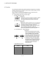
In this manual, the safety instructions are ranked as "DANGER" and "CAUTION".
DANGER
Indicates that incorrect handling may cause hazardous
conditions, resulting in death or severe injury.
CAUTION
Indicates that incorrect handling may cause hazardous
conditions, resulting in medium or slight personal injury or
physical damage.
CAUTION may also be linked to serious
Depending on circumstances, procedures indicated by
results.
In any case, it is important to follow the directions for usage.
Please save this manual to make it accessible when required and always forward it to the end user.
A-1
For Safe Operations
1. Prevention of electric shocks
DANGER
Never open the front case or terminal covers while the power is ON or the unit is running, as this
may lead to electric shocks.
Never run the unit with the front case or terminal cover removed. The high voltage terminal and
charged sections will be exposed and may lead to electric shocks.
Never open the front case or terminal cover at times other than wiring work or periodic
inspections even if the power is OFF. The insides of the Motion controller and servo amplifier are
charged and may lead to electric shocks.
Completely turn off the externally supplied power used in the system before mounting or
removing the module, performing wiring work, or inspections. Failing to do so may lead to electric
shocks.
When performing wiring work or inspections, turn the power OFF, wait at least ten minutes, and
then check the voltage with a tester, etc. Failing to do so may lead to electric shocks.
Be sure to ground the Motion controller, servo amplifier and servomotor. (Ground resistance :
100 or less) Do not ground commonly with other devices.
The wiring work and inspections must be done by a qualified technician.
Wire the units after installing the Motion controller, servo amplifier and servomotor. Failing to do
so may lead to electric shocks or damage.
Never operate the switches with wet hands, as this may lead to electric shocks.
Do not damage, apply excessive stress, place heavy things on or sandwich the cables, as this
may lead to electric shocks.
Do not touch the Motion controller, servo amplifier or servomotor terminal blocks while the power
is ON, as this may lead to electric shocks.
Do not touch the built-in power supply, built-in grounding or signal wires of the Motion controller
and servo amplifier, as this may lead to electric shocks.
2. For fire prevention
CAUTION
Install the Motion controller, servo amplifier, servomotor and regenerative resistor on
incombustible. Installing them directly or close to combustibles will lead to fire.
If a fault occurs in the Motion controller or servo amplifier, shut the power OFF at the servo
amplifier’s power source. If a large current continues to flow, fire may occur.
When using a regenerative resistor, shut the power OFF with an error signal. The regenerative
resistor may abnormally overheat due to a fault in the regenerative transistor, etc., and may lead
to fire.
Always take heat measures such as flame proofing for the inside of the control panel where the
servo amplifier or regenerative resistor is installed and for the wires used. Failing to do so may
lead to fire.
Do not damage, apply excessive stress, place heavy things on or sandwich the cables, as this
may lead to fire.
A-2
3. For injury prevention
CAUTION
Do not apply a voltage other than that specified in the instruction manual on any terminal.
Doing so may lead to destruction or damage.
Do not mistake the terminal connections, as this may lead to destruction or damage.
Do not mistake the polarity ( + / - ), as this may lead to destruction or damage.
Do not touch the heat radiating fins of controller or servo amplifier, regenerative resistor and
servomotor, etc., while the power is ON and for a short time after the power is turned OFF. In this
timing, these parts become very hot and may lead to burns.
Always turn the power OFF before touching the servomotor shaft or coupled machines, as these
parts may lead to injuries.
Do not go near the machine during test operations or during operations such as teaching.
Doing so may lead to injuries.
4. Various precautions
Strictly observe the following precautions.
Mistaken handling of the unit may lead to faults, injuries or electric shocks.
(1) System structure
CAUTION
Always install a leakage breaker on the Motion controller and servo amplifier power source.
If installation of an electromagnetic contactor for power shut off during an error, etc., is specified in
the instruction manual for the servo amplifier, etc., always install the electromagnetic contactor.
Install the emergency stop circuit externally so that the operation can be stopped immediately and
the power shut off.
Use the Motion controller, servo amplifier, servomotor and regenerative resistor with the correct
combinations listed in the instruction manual. Other combinations may lead to fire or faults.
Use the Motion controller, base unit and motion module with the correct combinations listed in the
instruction manual. Other combinations may lead to faults.
If safety standards (ex., robot safety rules, etc.,) apply to the system using the Motion controller,
servo amplifier and servomotor, make sure that the safety standards are satisfied.
Construct a safety circuit externally of the Motion controller or servo amplifier if the abnormal
operation of the Motion controller or servo amplifier differ from the safety directive operation in the
system.
In systems where coasting of the servomotor will be a problem during the forced stop, emergency
stop, servo OFF or power supply OFF, use dynamic brakes.
Make sure that the system considers the coasting amount even when using dynamic brakes.
In systems where perpendicular shaft dropping may be a problem during the forced stop,
emergency stop, servo OFF or power supply OFF, use both dynamic brakes and electromagnetic
brakes.
A-3
CAUTION
The dynamic brakes must be used only on errors that cause the forced stop, emergency stop, or
servo OFF. These brakes must not be used for normal braking.
The brakes (electromagnetic brakes) assembled into the servomotor are for holding applications,
and must not be used for normal braking.
The system must have a mechanical allowance so that the machine itself can stop even if the
stroke limits switch is passed through at the max. speed.
Use wires and cables that have a wire diameter, heat resistance and bending resistance
compatible with the system.
Use wires and cables within the length of the range described in the instruction manual.
The ratings and characteristics of the parts (other than Motion controller, servo amplifier and
servomotor) used in a system must be compatible with the Motion controller, servo amplifier and
servomotor.
Install a cover on the shaft so that the rotary parts of the servomotor are not touched during
operation.
There may be some cases where holding by the electromagnetic brakes is not possible due to the
life or mechanical structure (when the ball screw and servomotor are connected with a timing belt,
etc.). Install a stopping device to ensure safety on the machine side.
(2) Parameter settings and programming
CAUTION
Set the parameter values to those that are compatible with the Motion controller, servo amplifier,
servomotor and regenerative resistor model and the system application. The protective functions
may not function if the settings are incorrect.
The regenerative resistor model and capacity parameters must be set to values that conform to
the operation mode, servo amplifier and servo power supply module. The protective functions
may not function if the settings are incorrect.
Set the mechanical brake output and dynamic brake output validity parameters to values that are
compatible with the system application. The protective functions may not function if the settings
are incorrect.
Set the stroke limit input validity parameter to a value that is compatible with the system
application. The protective functions may not function if the setting is incorrect.
Set the servomotor encoder type (increment, absolute position type, etc.) parameter to a value
that is compatible with the system application. The protective functions may not function if the
setting is incorrect.
Set the servomotor capacity and type (standard, low-inertia, flat, etc.) parameter to values that
are compatible with the system application. The protective functions may not function if the
settings are incorrect.
Set the servo amplifier capacity and type parameters to values that are compatible with the
system application. The protective functions may not function if the settings are incorrect.
Use the program commands for the program with the conditions specified in the instruction
manual.
A-4
CAUTION
Set the sequence function program capacity setting, device capacity, latch validity range, I/O
assignment setting, and validity of continuous operation during error detection to values that are
compatible with the system application. The protective functions may not function if the settings
are incorrect.
Some devices used in the program have fixed applications, so use these with the conditions
specified in the instruction manual.
The input devices and data registers assigned to the link will hold the data previous to when
communication is terminated by an error, etc. Thus, an error correspondence interlock program
specified in the instruction manual must be used.
Use the interlock program specified in the intelligent function module's instruction manual for the
program corresponding to the intelligent function module.
(3) Transportation and installation
CAUTION
Transport the product with the correct method according to the mass.
Use the servomotor suspension bolts only for the transportation of the servomotor. Do not
transport the servomotor with machine installed on it.
Do not stack products past the limit.
When transporting the Motion controller or servo amplifier, never hold the connected wires or
cables.
When transporting the servomotor, never hold the cables, shaft or detector.
When transporting the Motion controller or servo amplifier, never hold the front case as it may fall
off.
When transporting, installing or removing the Motion controller or servo amplifier, never hold the
edges.
Install the unit according to the instruction manual in a place where the mass can be withstood.
Do not get on or place heavy objects on the product.
Always observe the installation direction.
Keep the designated clearance between the Motion controller or servo amplifier and control panel
inner surface or the Motion controller and servo amplifier, Motion controller or servo amplifier and
other devices.
Do not install or operate Motion controller, servo amplifiers or servomotors that are damaged or
that have missing parts.
Do not block the intake/outtake ports of the Motion controller, servo amplifier and servomotor with
cooling fan.
Do not allow conductive matter such as screw or cutting chips or combustible matter such as oil
enter the Motion controller, servo amplifier or servomotor.
The Motion controller, servo amplifier and servomotor are precision machines, so do not drop or
apply strong impacts on them.
Securely fix the Motion controller, servo amplifier and servomotor to the machine according to
the instruction manual. If the fixing is insufficient, these may come off during operation.
A-5
CAUTION
Always install the servomotor with reduction gears in the designated direction. Failing to do so
may lead to oil leaks.
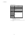
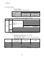
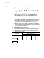
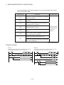
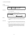
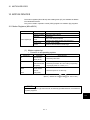
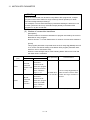
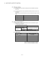
Store and use the unit in the following environmental conditions.
Environment
Ambient
temperature
Ambient humidity
Storage
temperature
Atmosphere
Conditions
Motion controller/Servo amplifier
According to each instruction manual.
According to each instruction manual.
According to each instruction manual.
Servomotor
0°C to +40°C (With no freezing)
(32°F to +104°F)
80% RH or less
(With no dew condensation)
-20°C to +65°C
(-4°F to +149°F)
Indoors (where not subject to direct sunlight).
No corrosive gases, flammable gases, oil mist or dust must exist
Altitude
1000m (3280.84ft.) or less above sea level
Vibration
According to each instruction manual
When coupling with the synchronous encoder or servomotor shaft end, do not apply impact such
as by hitting with a hammer. Doing so may lead to detector damage.
Do not apply a load larger than the tolerable load onto the synchronous encoder and servomotor
shaft. Doing so may lead to shaft breakage.
When not using the module for a long time, disconnect the power line from the Motion controller
or servo amplifier.
Place the Motion controller and servo amplifier in static electricity preventing vinyl bags and store.
When storing for a long time, please contact with our sales representative.
Also, execute a trial operation.
A-6
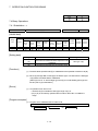
(4) Wiring
CAUTION
Correctly and securely wire the wires. Reconfirm the connections for mistakes and the terminal
screws for tightness after wiring. Failing to do so may lead to run away of the servomotor.
After wiring, install the protective covers such as the terminal covers to the original positions.
Do not install a phase advancing capacitor, surge absorber or radio noise filter (option FR-BIF)
on the output side of the servo amplifier.
Correctly connect the output side (terminal U, V, W) and ground. Incorrect connections will lead
the servomotor to operate abnormally.
Do not connect a commercial power supply to the servomotor, as this may lead to trouble.
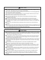
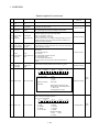
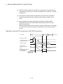
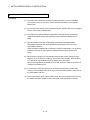
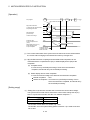
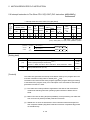
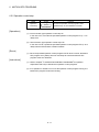
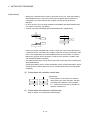
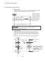
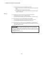
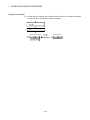
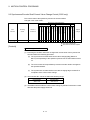
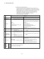
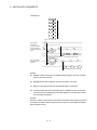
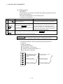
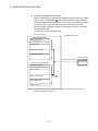
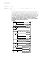
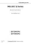
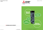
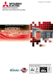
Do not mistake the direction of the surge absorbing diode
installed on the DC relay for the control signal output of brake
Servo amplifier
signals, etc. Incorrect installation may lead to signals not being
VIN
(24VDC)
output when trouble occurs or the protective functions not
functioning.
Control output
RA
signal
Do not connect or disconnect the connection cables between
each unit, the encoder cable or PLC expansion cable while the
power is ON.
Securely tighten the cable connector fixing screws and fixing mechanisms. Insufficient fixing may
lead to the cables combing off during operation.
Do not bundle the power line or cables.
(5) Trial operation and adjustment
CAUTION
Confirm and adjust the program and each parameter before operation. Unpredictable
movements may occur depending on the machine.
Extreme adjustments and changes may lead to unstable operation, so never make them.
When using the absolute position system function, on starting up, and when the Motion
controller or absolute value motor has been replaced, always perform a home position return.
A-7
(6) Usage methods
CAUTION
Immediately turn OFF the power if smoke, abnormal sounds or odors are emitted from the
Motion controller, servo amplifier or servomotor.
Always execute a test operation before starting actual operations after the program or
parameters have been changed or after maintenance and inspection.
Do not attempt to disassemble and repair the units excluding a qualified technician whom our
company recognized.
Do not make any modifications to the unit.
Keep the effect or electromagnetic obstacles to a minimum by installing a noise filter or by using
wire shields, etc. Electromagnetic obstacles may affect the electronic devices used near the
Motion controller or servo amplifier.
When using the CE Mark-compliant equipment, refer to the "EMC Installation Guidelines" (data
number IB(NA)-67339) for the Motion controllers and refer to the corresponding EMC guideline
information for the servo amplifiers, inverters and other equipment.
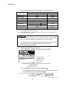
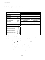
Use the units with the following conditions.
Item
Conditions
Input power
According to each instruction manual.
Input frequency
According to each instruction manual.
Tolerable momentary power failure
According to each instruction manual.
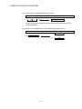
(7) Corrective actions for errors
CAUTION
If an error occurs in the self diagnosis of the Motion controller or servo amplifier, confirm the
check details according to the instruction manual, and restore the operation.
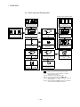
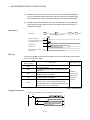
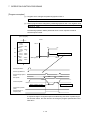
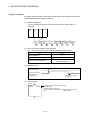
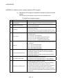
If a dangerous state is predicted in case of a power failure or product failure, use a servomotor
with electromagnetic brakes or install a brake mechanism externally.
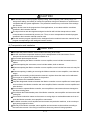
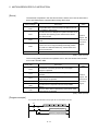
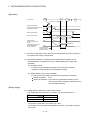
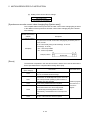
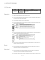
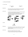
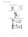
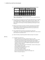
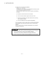
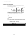
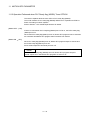
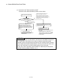
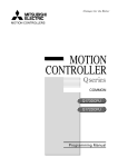
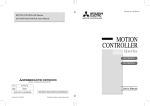
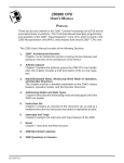
Use a double circuit construction so that the electromagnetic brake operation circuit can be
operated by emergency stop signals set externally.
Shut off with servo ON signal OFF,
alarm, electromagnetic brake signal.
Servomotor
RA1
Electromagnetic
brakes
Shut off with the
emergency stop
signal (EMG).
EMG
24VDC
If an error occurs, remove the cause, secure the safety and then resume operation after alarm
release.
The unit may suddenly resume operation after a power failure is restored, so do not go near the
machine. (Design the machine so that personal safety can be ensured even if the machine
restarts suddenly.)
A-8
(8) Maintenance, inspection and part replacement
CAUTION
Perform the daily and periodic inspections according to the instruction manual.
Perform maintenance and inspection after backing up the program and parameters for the Motion
controller and servo amplifier.
Do not place fingers or hands in the clearance when opening or closing any opening.
Periodically replace consumable parts such as batteries according to the instruction manual.
Do not touch the lead sections such as ICs or the connector contacts.
Before touching the module, always touch grounded metal, etc. to discharge static electricity from
human body. Failure to do so may cause the module to fail or malfunction.
Do not directly touch the module's conductive parts and electronic components.
Touching them could cause an operation failure or give damage to the module.
Do not place the Motion controller or servo amplifier on metal that may cause a power leakage
or wood, plastic or vinyl that may cause static electricity buildup.
Do not perform a megger test (insulation resistance measurement) during inspection.
When replacing the Motion controller or servo amplifier, always set the new module settings
correctly.
When the Motion controller or absolute value motor has been replaced, carry out a home
position return operation using one of the following methods, otherwise position displacement
could occur.
1) After writing the servo data to the Motion controller using programming software, switch on the
power again, then perform a home position return operation.
2) Using the backup function of the programming software, load the data backed up before
replacement.
After maintenance and inspections are completed, confirm that the position detection of the
absolute position detector function is correct.
Do not drop or impact the battery installed to the module.
Doing so may damage the battery, causing battery liquid to leak in the battery. Do not use the
dropped or impacted battery, but dispose of it.
Do not short circuit, charge, overheat, incinerate or disassemble the batteries.
The electrolytic capacitor will generate gas during a fault, so do not place your face near the
Motion controller or servo amplifier.
The electrolytic capacitor and fan will deteriorate. Periodically replace these to prevent secondary
damage from faults. Replacements can be made by our sales representative.
Lock the control panel and prevent access to those who are not certified to handle or install
electric equipment.
Do not burn or break a module and servo amplifier. Doing so may cause a toxic gas.
A-9
(9) About processing of waste
When you discard Motion controller, servo amplifier, a battery (primary battery) and other option
articles, please follow the law of each country (area).
CAUTION
This product is not designed or manufactured to be used in equipment or systems in situations
that can affect or endanger human life.
When considering this product for operation in special applications such as machinery or systems
used in passenger transportation, medical, aerospace, atomic power, electric power, or
submarine repeating applications, please contact your nearest Mitsubishi sales representative.
Although this product was manufactured under conditions of strict quality control, you are strongly
advised to install safety devices to forestall serious accidents when it is used in facilities where a
breakdown in the product is likely to cause a serious accident.
(10) General cautions
All drawings provided in the instruction manual show the state with the covers and safety
partitions removed to explain detailed sections. When operating the product, always return the
covers and partitions to the designated positions, and operate according to the instruction
manual.
A - 10
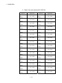
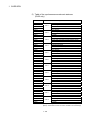
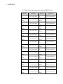
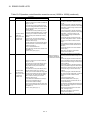
REVISIONS
The manual number is given on the bottom left of the back cover.
Print Date
Jun., 2002
Feb., 2004
Mar., 2006
Apr., 2010
Manual Number
Revision
IB(NA)-0300042-A First edition
IB(NA)-0300042-B [Addition model]
Q173CPUN-T/Q172CPUN-T, A31TU-D3K13/A31TU-DNK13,
Q172EX-S1, Q173PX-S1, Q00CPU, Q01CPU, 64AD, Q68ADV, Q68ADI,
Q62DA, Q64DA, Q68DAV, Q68DAI, Q170TUD3CBL3M,
Q170TUDNCBL3M, Q170TUDNCBL03M-A, Q170TUTM, A31TUD3TM,
FR-V5 0- , Software for SV43
[Addition function]
For WindowsXP, Home position return function, ROM operation function,
Online change function
[Additional correction/partial correction]
Safety precautions, About processing of waste, Startup slow of the
Multiple CPU system, User file list, Error code list, etc.
[partial correction]
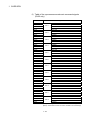
IB(NA)-0300042-C [Addition model]
Q62P, Q172EX-S2, Q172EX-S3, Q170ENC
[Addition function]
Cam axis command signal, Smoothing clutch complete signal, Gain
changing signal, Real mode axis information register, Motion SFC
instruction "FMOV", Bit device setting by Motion SFC instruction, Security
function
[Additional correction/partial correction]
Safety precautions, User file list, Error code list, Warranty, Manual model
code (1CT781 1XB781), etc.
IB(NA)-0300042-D [Additional correction/partial correction]
Safety precautions, "1.6.1 I/O No. for I/O modules and intelligent function
modules", Warranty
Japanese Manual Version IB(NA)-0300023
This manual confers no industrial property rights or any rights of any other kind, nor does it confer any patent
licenses. Mitsubishi Electric Corporation cannot be held responsible for any problems involving industrial property
rights which may occur as a result of using the contents noted in this manual.
© 2002 MITSUBISHI ELECTRIC CORPORATION
A - 11
INTRODUCTION
Thank you for choosing the Q173CPU(N)/Q172CPU(N) Motion Controller.
Please read this manual carefully so that equipment is used to its optimum.
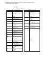
CONTENTS
Safety Precautions .........................................................................................................................................A- 1
Revisions ........................................................................................................................................................A-11
Contents .........................................................................................................................................................A-12
About Manuals ...............................................................................................................................................A-18
1. OVERVIEW
1- 1 to 1-96
1.1 Overview................................................................................................................................................... 1- 1
1.2 Features ................................................................................................................................................... 1- 3
1.2.1 Features of Motion CPU ................................................................................................................... 1- 3
1.2.2 Basic specifications of Q173CPU(N)/Q172CPU(N)......................................................................... 1- 6
1.2.3 Operation control/transition control specifications ........................................................................... 1- 9
1.2.4 Differences between Q173CPU(N)/Q172CPU(N)and A173UHCPU/A172SHCPUN.................... 1-13
1.2.5 Positioning dedicated devices/special relays/special registers ....................................................... 1-15
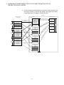
1.3 Hardware Configuration ........................................................................................................................... 1-55
1.3.1 Motion system configuration ............................................................................................................. 1-55
1.3.2 Q173CPU(N) System overall configuration...................................................................................... 1-61
1.3.3 Q172CPU(N) System overall configuration...................................................................................... 1-63
1.3.4 Software packages............................................................................................................................ 1-65
1.3.5 Restrictions on motion systems........................................................................................................ 1-69
1.4 Multiple CPU System ............................................................................................................................... 1-71
1.4.1 Overview............................................................................................................................................ 1-71
1.4.2 Installation of PLC CPU and Motion CPU ........................................................................................ 1-72
1.4.3 Precautions for using Q series I/O modules and intelligent function modules................................ 1-73
1.4.4 Modules subject to installation restrictions ....................................................................................... 1-74
1.4.5 Processing time of the Multiple CPU system ................................................................................... 1-75
1.4.6 How to reset the Multiple CPU system............................................................................................. 1-76
1.4.7 Processing at a CPU DOWN error occurrence by a PLC CPU or Q173CPU(N)/Q172CPU(N).... 1-77
1.5 System Settings ....................................................................................................................................... 1-80
1.5.1 System data settings......................................................................................................................... 1-80
1.5.2 Common system parameters ........................................................................................................... 1-81
1.5.3 Individual parameters........................................................................................................................ 1-87
1.6 Assignment of I/O No............................................................................................................................... 1-92
1.6.1 I/O No. for I/O modules and intelligent function modules ................................................................ 1-92
1.6.2 I/O No. of PLC CPU and Q173CPU(N)/Q172CPU(N)..................................................................... 1-95
1.6.3 Setting I/O No. ................................................................................................................................... 1-96
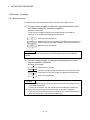
2. STARTING UP THE MULTIPLE CPU SYSTEM
2- 1 to 2- 2
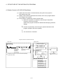
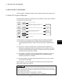
2.1 Startup Flow of the Multiple CPU System ............................................................................................... 2- 1
A - 12
3. COMMUNICATION BETWEEN THE PLC CPU AND THE MOTION CPU IN
THE MULTIPLE CPU SYSTEM
3- 1 to 3-26
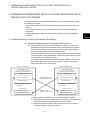
3.1 Automatic Refresh Function of The Shared CPU Memory .................................................................... 3- 1
3.2 Control Instruction from the PLC CPU to The Motion CPU (Motion dedicated instructions) ................ 3-20
3.3 Reading/Writing Device Data .................................................................................................................. 3-21
3.4 Shared CPU Memory............................................................................................................................... 3-22
4. STRUCTURE OF THE MOTION CPU PROGRAM
4- 1 to 4- 4
4.1 Motion Control in SV13/SV22 Real Mode............................................................................................... 4- 2
4.2 Motion Control in SV22 Virtual Mode ...................................................................................................... 4- 3
5. MOTION DEDICATED PLC INSTRUCTION
5- 1 to 5-48
5.1 Motion Dedicated PLC Instruction........................................................................................................... 5- 1
5.1.1 Restriction item of the Motion dedicated PLC instruction ................................................................ 5- 1
5.2 Motion SFC Start Request from The PLC CPU to The Motion CPU:
S(P).SFCS (PLC instruction: S(P).SFCS ) ............................................................................................ 5- 9
5.3 Servo Program Start Request from The PLC CPU to The Motion CPU:
S(P).SVST (PLC instruction: S(P).SVST ) ........................................................................................... 5-12
5.4 Current Value Change Instruction from The PLC CPU to The Motion CPU:
S(P).CHGA (PLC instruction: S(P).CHGA ) .......................................................................................... 5-17
5.5 Speed Change Instruction from The PLC CPU to The Motion CPU:
S(P).CHGV (PLC instruction: S(P).CHGV ) .......................................................................................... 5-30
5.6 Torque Limit Value Change Request Instruction from The PLC CPU to The Motion CPU:
S(P).CHGT (PLC instruction: S(P).CHGT )........................................................................................... 5-34
5.7 Write from The PLC CPU to The Motion CPU: S(P).DDWR (PLC instruction: S(P).DDWR )............. 5-38
5.8 Read from The Devices of The Motion CPU: S(P).DDRD (PLC instruction: S(P).DDRD ) ................. 5-42
5.9 Interrupt Instruction to The Other CPU: S(P).GINT (PLC instruction: S(P).GINT ).............................. 5-46
6. MOTION SFC PROGRAMS
6- 1 to 6-28
6.1 Motion SFC Program Configuration ........................................................................................................ 6- 1
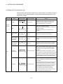
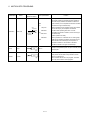
6.2 Motion SFC Chart Symbol List ................................................................................................................ 6- 2
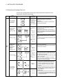
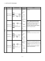
6.3 Branch and Coupling Chart List............................................................................................................... 6- 5
6.4 Motion SFC Program Name .................................................................................................................... 6- 9
6.5 Steps......................................................................................................................................................... 6-10
6.5.1 Motion control step ............................................................................................................................ 6-10
6.5.2 Operation control step....................................................................................................................... 6-11
6.5.3 Subroutine call/start step................................................................................................................... 6-12
6.5.4 Clear step .......................................................................................................................................... 6-14
6.6 Transitions ................................................................................................................................................ 6-15
6.7 Jump, Pointer ........................................................................................................................................... 6-17
6.8 END .......................................................................................................................................................... 6-17
6.9 Branches, Couplings................................................................................................................................ 6-18
6.9.1 Series transition................................................................................................................................. 6-18
A - 13
6.9.2 Selective branch, selective coupling................................................................................................. 6-19
6.9.3 Parallel branch, parallel coupling...................................................................................................... 6-20
6.10 Y/N Transitions....................................................................................................................................... 6-22
6.11 Motion SFC Comments ......................................................................................................................... 6-26
7. OPERATION CONTROL PROGRAMS
7- 1 to 7-96
7.1 Operation Control Programs.................................................................................................................... 7- 1
7.2 Device Descriptions ................................................................................................................................. 7- 7
7.3 Constant Descriptions.............................................................................................................................. 7- 9
7.4 Binary Operations .................................................................................................................................... 7-10
7.4.1 Substitution : =................................................................................................................................... 7-10
7.4.2 Addition : +......................................................................................................................................... 7-12
7.4.3 Subtraction : .................................................................................................................................. 7-13
7.4.4 Multiplication : * ................................................................................................................................. 7-15
7.4.5 Division : / .......................................................................................................................................... 7-16
7.4.6 Remainder : %................................................................................................................................... 7-17
7.5 Bit Operations........................................................................................................................................... 7-18
7.5.1 Bit inversion(Complement) : ~ .......................................................................................................... 7-18
7.5.2 Bit logical AND : & ............................................................................................................................. 7-19
7.5.3 Bit logical OR : |................................................................................................................................. 7-20
7.5.4 Bit exclusive logical OR : ^................................................................................................................ 7-21
7.5.5 Bit right shift : >>................................................................................................................................ 7-22
7.5.6 Bit left shift : <<.................................................................................................................................. 7-23
7.5.7 Sign inversion(Complement of 2) : ............................................................................................... 7-24
7.6 Standard Functions .................................................................................................................................. 7-25
7.6.1 Sine : SIN........................................................................................................................................... 7-25
7.6.2 Cosine : COS..................................................................................................................................... 7-26
7.6.3 Tangent : TAN ................................................................................................................................... 7-27
7.6.4 Arcsine : ASIN ................................................................................................................................... 7-28
7.6.5 Arccosine : ACOS ............................................................................................................................. 7-29
7.6.6 Arctangent : ATAN ............................................................................................................................ 7-30
7.6.7 Square root : SQRT .......................................................................................................................... 7-31
7.6.8 Natural logarithm : LN ....................................................................................................................... 7-32
7.6.9 Exponential operation : EXP............................................................................................................. 7-33
7.6.10 Absolute value : ABS ...................................................................................................................... 7-34
7.6.11 Round-off : RND.............................................................................................................................. 7-35
7.6.12 Round-down : FIX ........................................................................................................................... 7-36
7.6.13 Round-up : FUP .............................................................................................................................. 7-37
7.6.14 BCD BIN conversion : BIN ......................................................................................................... 7-38
7.6.15 BIN BCD conversion : BCD........................................................................................................ 7-39
7.7 Type Conversions .................................................................................................................................... 7-40
7.7.1 Signed 16-bit integer value conversion : SHORT ............................................................................ 7-40
7.7.2 Unsigned 16-bit integer value conversion : USHORT ..................................................................... 7-41
7.7.3 Signed 32-bit integer value conversion : LONG............................................................................... 7-42
7.7.4 Unsigned 32-bit integer value conversion : ULONG........................................................................ 7-43
7.7.5 Signed 64-bit floating-point value conversion : FLOAT ................................................................... 7-44
7.7.6 Unsigned 64-bit floating-point value conversion : UFLOAT ............................................................ 7-45
A - 14
7.8 Bit Device Statuses .................................................................................................................................. 7-46
7.8.1 ON (Normally open contact) : (None) ............................................................................................... 7-46
7.8.2 OFF (Normally closed contact) : !..................................................................................................... 7-47
7.9 Bit Device Controls................................................................................................................................... 7-48
7.9.1 Device set : SET................................................................................................................................ 7-48
7.9.2 Device reset : RST ............................................................................................................................ 7-50
7.9.3 Device output : DOUT ....................................................................................................................... 7-52
7.9.4 Device input : DIN ............................................................................................................................. 7-53
7.9.5 Bit device output : OUT .................................................................................................................... 7-54
7.10 Logical Operations ................................................................................................................................. 7-56
7.10.1 Logical acknowledgement : (None) ................................................................................................ 7-56
7.10.2 Logical negation : ! .......................................................................................................................... 7-57
7.10.3 Logical AND : * ................................................................................................................................ 7-58
7.10.4 Logical OR : +.................................................................................................................................. 7-59
7.11 Comparison Operations......................................................................................................................... 7-60
7.11.1 Equal to : == .................................................................................................................................... 7-60
7.11.2 Not equal to : != ............................................................................................................................... 7-61
7.11.3 Less than : <.................................................................................................................................... 7-62
7.11.4 Less than or equal to : <= ............................................................................................................... 7-63
7.11.5 More than : > ................................................................................................................................... 7-64
7.11.6 More than or equal to : >=............................................................................................................... 7-65
7.12 Motion-Dedicated Functions(CHGV, CHGT) ........................................................................................ 7-66
7.12.1 Speed change request : CHGV ...................................................................................................... 7-66
7.12.2 Torque limit value change request : CHGT.................................................................................... 7-72
7.13 Other Instructions................................................................................................................................... 7-74
7.13.1 Event task enable : EI ..................................................................................................................... 7-74
7.13.2 Event task disable : DI .................................................................................................................... 7-75
7.13.3 No operation : NOP......................................................................................................................... 7-76
7.13.4 Block transfer : BMOV .................................................................................................................... 7-77
7.13.5 Same data block transfer : FMOV .................................................................................................. 7-80
7.13.6 Write device data to shared CPU memory of the self CPU : MULTW .......................................... 7-82
7.13.7 Read device data from shared CPU memory of the other CPU: MULTR..................................... 7-85
7.13.8 Write device data to intelligent function module/special function module : TO............................. 7-88
7.13.9 Read device data from intelligent function module/special function module : FROM .................. 7-91
7.13.10 Time to wait : TIME ....................................................................................................................... 7-94
7.14 Comment Statement : //......................................................................................................................... 7-96
8. TRANSITION PROGRAMS
8- 1 to 8- 2
8.1 Transition Programs................................................................................................................................. 8- 1
9. MOTION CONTROL PROGRAMS
9- 1 to 9-22
9.1 Servo Instruction List................................................................................................................................ 9- 1
9.2 Servomotor/Virtual Servomotor Shaft Current Value Change................................................................ 9-14
9.3 Synchronous Encoder Shaft Current Value Change Control (SV22 Only)............................................ 9-17
9.4 Cam Shaft Within-One-Revolution Current Value Change Control (SV22 Only) .................................. 9-20
A - 15
9.5 Programming Instructions........................................................................................................................ 9-22
9.5.1 Cancel • start ..................................................................................................................................... 9-22
9.5.2 Indirect designation using motion devices........................................................................................ 9-22
10. MOTION DEVICES
10- 1 to 10- 6
10.1 Motion Registers (#0 to #8191) ............................................................................................................ 10- 1
10.2 Coasting Timer (FT).............................................................................................................................. 10- 6
11. MOTION SFC PARAMETER
11- 1 to 11-20
11.1 Task Definitions.................................................................................................................................... 11- 1
11.2 Number of Consecutive Transitions and Task Operation .................................................................. 11- 2
11.2.1 Number of consecutive transitions ............................................................................................... 11- 2
11.2.2 Task operation............................................................................................................................... 11- 3
11.3 Execution Status of The Multiple Task................................................................................................ 11- 7
11.4 Task Parameters.................................................................................................................................. 11- 8
11.5 Program Parameters............................................................................................................................ 11-10
11.6 How to Start The Motion SFC Program .............................................................................................. 11-16
11.6.1 Automatic start .............................................................................................................................. 11-16
11.6.2 Start from the Motion SFC program ............................................................................................. 11-16
11.6.3 Start from PLC (PLC instruction S(P).SFCS )............................................................................ 11-16
11.7 How to End The Motion SFC Program ............................................................................................... 11-17
11.8 How to Change from One Motion SFC Program to Another.............................................................. 11-17
11.9 How to Manage The Executing Program ............................................................................................ 11-17
11.10 Operation Performed at CPU Power-Off or Reset.......................................................................... 11-18
11.11 Operation Performed when CPU is Switched from RUN/STOP ...................................................... 11-18
11.12 Operation Performed when PLC Ready flag (M2000) Turns OFF/ON ............................................ 11-19
11.13 Operation at The Error Occurrence................................................................................................... 11-20
12. USER FILES
12- 1 to 12- 8
12.1 Projects................................................................................................................................................. 1212.2 User File List ........................................................................................................................................ 1212.3 Online Change in The Motion SFC Program ...................................................................................... 1212.3.1 Operating method for The Online Change................................................................................... 1212.3.2 Transfer of program ...................................................................................................................... 1213. LIMIT SWITCH OUTPUT FUNCTION
1
2
3
4
7
13- 1 to 13- 8
13.1 Operations............................................................................................................................................ 13- 1
13.2 Limit Output Setting Data..................................................................................................................... 13- 4
14. ROM OPERATION FUNCTION
14- 1 to 14-12
14.1 About the ROM Operation Function.................................................................................................... 14- 1
14.2 Specifications of LED • Switch............................................................................................................. 14- 3
14.3 ROM Operation Function Details ........................................................................................................ 14- 5
14.4 Operating Procedure of "ROM writing" ............................................................................................... 14-11
A - 16
15. SECURITY FUNCTION
15- 1 to 15- 6
15.1 Password Registration/change............................................................................................................ 1515.2 Password Clearance............................................................................................................................ 1515.3 Password Check .................................................................................................................................. 1515.4 Password Save .................................................................................................................................... 1515.5 Clear All ................................................................................................................................................ 1516. COMMUNICATIONS VIA NETWORK
1
3
4
5
6
16- 1 to 16-10
16.1 Specifications of The Communications via Network........................................................................... 1616.2 Access Range of The Communications via Network ......................................................................... 1616.2.1 Network configuration via the MELSECNET/10(H) or the Ethernet............................................ 1616.2.2 Network configuration via the CC-Link ......................................................................................... 1616.2.3 Network configuration via the RS422/485.................................................................................... 1616.2.4 Network configuration which MELSECNET/10 (H), Ethernet, CC-Link, RS422/485 were mixed
.................................................................................................................................................................. 16-
2
3
3
5
6
7
17. MONITOR FUNCTION OF THE MAIN CYCLE
17- 1 to 17- 2
18. SERVO PARAMETER READING FUNCTION
18- 1 to 18- 2
18.1 About The Servo Parameter Read Request Devices......................................................................... 18- 1
18.2 Operating Procedure of The Servo Parameter Reading Function..................................................... 18- 2
19. ERROR CODE LISTS
19- 1 to 19-18
19.1 Reading Procedure for Error Codes.................................................................................................... 19- 1
19.2 Motion SFC Error Code List ................................................................................................................ 19- 2
19.3 Motion SFC Parameter Errors ............................................................................................................. 19-11
19.4 Multiple CPU Error Codes ................................................................................................................... 19-13
19.4.1 Self-diagnosis error code .............................................................................................................. 19-13
19.4.2 Release of self-diagnosis error ..................................................................................................... 19-18
APPENDICES
APP- 1 to APP-32
APPENDIX 1 Processing Times...............................................................................................................APP- 1
APPENDIX 1.1 Processing time of operation control/Transition instruction .......................................APP- 1
APPENDIX 2 Sample Program ................................................................................................................APP- 9
APPENDIX 2.1 Program example to execute the Multiple CPU dedicated instruction continuously.APP- 9
APPENDIX 2.2 The program example to execute plural Multiple CPU instruction by the instructions of
one time........................................................................................................................APP-11
APPENDIX 2.3 Motion control example by Motion SFC program.......................................................APP-13
APPENDIX 2.4 Continuation execution example at the subroutine re-start by the Motion SFC program
.....................................................................................................................................APP-24
APPENDIX 2.5 Continuation execution example after the stop by the Motion SFC program............APP-28
A - 17
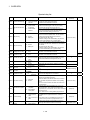
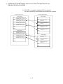
About Manuals
The following manuals are related to this product.
Referring to this list, please request the necessary manuals.
Related Manuals
(1) Motion controller
Manual Number
(Model Code)
Manual Name
Q173CPU(N)/Q172CPU(N) Motion controller User's Manual
This manual explains specifications of the Motion CPU modules, Q172LX Servo external signal interface
module, Q172EX Serial absolute synchronous encoder interface module, Q173PX Manual pulse
generator interface module, Teaching units, Power supply modules, Servo amplifiers, SSCNET cables,
IB-0300040
(1XB780)
synchronous encoder cables and others.
(Optional)
Q173CPU(N)/Q172CPU(N) Motion controller (SV13/SV22) Programming Manual
(REAL MODE)
This manual explains the servo parameters, positioning instructions, device list, error list and others.
IB-0300043
(1XB782)
(Optional)
Q173CPU(N)/Q172CPU(N) Motion controller (SV22) Programming Manual
(VIRTUAL MODE)
This manual describes the dedicated instructions use to the synchronous control by virtual main shaft,
mechanical system program create mechanical module.
IB-0300044
(1XB783)
This manual explains the servo parameters, positioning instructions, device list, error list and others.
(Optional)
Q173CPU(N)/Q172CPU(N) Motion controller (SV43) Programming Manual
This manual describes the dedicated instructions to execute the positioning control by Motion program of
EIA language (G-code).
This manual explains the Multiple CPU system configuration, performance specifications, functions,
programming, debugging, servo parameters, positioning instructions, device list error list and others.
(Optional)
A - 18
IB-0300070
(1CT784)
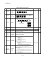
(2) PLC
Manual Number
(Model Code)
Manual Name
QCPU User's Manual (Hardware Design, Maintenance and Inspection)
This manual explains the specifications of the QCPU modules, power supply modules, base units,
extension cables, memory card battery, and the maintenance/inspection for the system, trouble shooting,
SH-080483ENG
(13JR73)
error codes and others.
(Optional)
Qn(H)/QnPH/QnPRHCPUCPU User's Manual (Function Explanation, Program
Fundamentals)
This manual explains the functions, programming methods and devices and others to create programs
with the QCPU.
SH-080808ENG
(13JZ28)
(Optional)
QCPU User's Manual (Multiple CPU System)
This manual explains Multiple CPU system overview, system configuration, I/O modules, communication
between CPU modules and communication with the I/O modules or intelligent function modules.
SH-080485ENG
(13JR75)
(Optional)
QCPU Programming Manual (Common Instructions)
This manual explains how to use the sequence instructions, basic instructions, application instructions and
micro computer program.
SH-080809ENG
(13JW10)
(Optional)
QCPU (Q Mode)/QnACPU Programming Manual (PID Control Instructions)
SH-080040
(13JF59)
This manual explains the dedicated instructions used to exercise PID control.
(Optional)
QCPU (Q Mode)/QnACPU Programming Manual (SFC)
This manual explains the system configuration, performance specifications, functions, programming,
debugging, error codes and others of MELSAP3.
SH-080041
(13JF60)
(Optional)
I/O Module Type Building Block User's Manual
This manual explains the specifications of the I/O modules, connector, connector/terminal block
conversion modules and others.
(Optional)
A - 19
SH-080042
(13JL99)
MEMO
A - 20
1 OVERVIEW
1. OVERVIEW
1
1.1 Overview
This programming manual describes the Motion SFC program and Multiple CPU
system of the operating system software packages "SW6RN-SV13Q ", "SW6RNSV22Q " for Motion CPU module(Q173CPU(N)/Q172CPU(N)).
In this manual, the following abbreviations are used.
Generic term/Abbreviation
Description
Q173CPU(N)/Q172CPU(N) or
Q173CPUN/Q172CPUN/Q173CPUN-T/Q172CPUN-T/Q173CPU/Q172CPU
Motion CPU (module)
Motion CPU module
Q172LX/Q172EX/Q173PX
Q172LX Servo external signals interface module/
(Note-1)
Q172EX(-S1/-S2/-S3) Serial absolute synchronous encoder interface module
/
or Motion module
Q173PX(-S1) Manual pulse generator interface module
MR-H-BN
Servo amplifier model MR-H BN
MR-J2 -B
Servo amplifier model MR-J2S- B/MR-J2M-B/MR-J2- B/MR-J2-03B5
AMP or Servo amplifier
QCPU, PLC CPU
or PLC CPU module
Multiple CPU system
or Motion system
General name for "Servo amplifier model MR-H BN/MR-J2S- B/MR-J2M-B/
MR-J2- B/MR-J2-03B5, Vector inverter FREQROL-V500 series"
Qn(H)CPU
Abbreviation for "Multiple PLC system of the Q series"
Abbreviation for "CPU No.n (n= 1 to 4) of the CPU module for the Multiple CPU
CPUn
system"
Programming software package
General name for "MT Developer" and "GX Developer"
Operating system software
General name for "SW RN-SV Q "
Operating system software for conveyor assembly use (Motion SFC) :
SV13
SW6RN-SV13Q
Operating system software for automatic machinery use (Motion SFC) :
SV22
SW6RN-SV22Q
MT Developer
GX Developer
Manual pulse generator
or MR-HDP01
Serial absolute synchronous encoder
or MR-HENC/Q170ENC
SSCNET
(Note-2)
Absolute position system
Abbreviation for Integrated start-up support software package "MT Developer"
Abbreviation for MELSEC PLC programming software package "GX Developer
(Version 6 or later)"
Abbreviation for "Manual pulse generator (MR-HDP01)"
Abbreviation for "Serial absolute synchronous encoder (MR-HENC/Q170ENC)"
High speed serial communication between Motion controller and servo amplifier
General name for "System using the servomotor and servo amplifier for absolute
position"
Cooling fan unit
Cooling fan unit (Q170FAN)
Dividing unit
Dividing unit (Q173DV)
Battery unit
Battery unit (Q170BAT)
1-1
1 OVERVIEW
Generic term/Abbreviation
Description
A 0BD-PCF
A10BD-PCF/A30BD-PCF SSC I/F board
SSC I/F communication cable
Abbreviation for "Cable for SSC I/F board/card"
Teaching Unit
A31TU-D3 /A31TU-DN
or A31TU-D3 /A31TU-DN
(Note-3)
Teaching unit
Abbreviation for "MELSECNET/H module/Ethernet module/CC-Link module/
Intelligent function module
Serial communication module"
Vector inverter (FR-V500)
Vector inverter FREQROL-V500 series
(Note-1) : Q172EX can be used in SV22.
(Note-2) : SSCNET: Servo System Controller NETwork
(Note-3) : Teaching unit can be used in SV13.
REMARK
For information about the each module, design method for program and parameter,
refer to the following manuals relevant to each module.
Item
Reference Manual
Motion CPU module/Motion unit
Q173CPU(N)/Q172CPU(N) User’s Manual
PLC CPU, peripheral devices for PLC program design, I/O
modules and intelligent function module
Operation method for MT Developer
Manual relevant to each module
Help of each software
• Design method for positioning control
SV13/SV22
program in the real mode
Q173CPU(N)/Q172CPU(N) Motion controller
• Design method for positioning control
(SV13/SV22) Programming Manual (REAL MODE)
parameter
SV22
(Virtual mode)
• Design method for mechanical system
program
Q173CPU(N)/Q172CPU(N) Motion controller (SV22)
Programming Manual (VIRTUAL MODE)
1-2
1 OVERVIEW
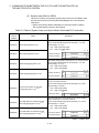
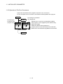
1.2 Features
The Motion CPU and Multiple CPU system have the following features.
1.2.1 Features of Motion CPU
(1) Q series PLC Multiple CPU system
(a) The load of control processing for each CPU can be distributed by
controlling the complicated servo control with the Motion CPU, and the
machine control or information control with the PLC CPU, and flexible
system configuration can be realized.
(b) The Motion CPU and PLC CPU are selected flexibly, and the Multiple CPU
system up to 4 CPU modules can be realized.
The Motion CPU module for the number of axis to be used can be selected.
Q173CPU(N)
: Up to 32 axes
Q172CPU(N)
: Up to 8 axes
The PLC CPU module for the program capacity to be used can be selected.
(One or more PLC CPU is necessary with the Multiple CPU system.)
Q00CPU
: 8k steps
Q01CPU
: 14k steps
Q02CPU, Q02HCPU
: 28k steps
Q06HCPU
: 60k steps
Q12HCPU
: 124k steps
Q25HCPU
: 252k steps
(c) The device data of other CPU can be used as the device data of self CPU
because the Multiple CPU automatic refresh may do automatically data
giving and receiving between each CPU of the Multiple CPU system.
(d) The device data access of the Motion CPU and the Motion SFC program
start can be executed from PLC CPU by the Motion dedicated PLC
instruction.
(2) Programming in the Motion SFC programs
(a) Since a program intelligible for anyone can be created in flow chart form by
macking a sequence of machine operation correspond to each operation
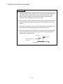
step, maintenance nature improves.
(b) Since transition conditions are judged with Motion CPU side and positioning
starts, there is not dispersion in the response time influenced by PLC scan
time.
1-3
1 OVERVIEW
(c) High speed and high response processing is realizable with the step
processing method (only active steps) of Motion SFC.
(d) Not only positioning control but also numerical operations, device SET/RST,
etc. can be processed with Motion CPU side, making via PLC CPU is
unnecessary and a tact time can be shortened.
(e) By transition condition description peculiar to Motion SFC, the instructions to
servo amplifier is possible at completion of starting condition.
(f) By transition condition description peculiar to Motion SFC, after starting,
transition to next step is possible without waiting for positioning completion.
(g) Motion SFC program that responds and executes it at high speed for
interrupt input from external source can be set.
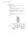
(h) Motion SFC program executed in the fixed cycle (0.88ms, 1.77ms, 3.55ms,
7.11ms, 14.2ms) by synchronizing to the Motion operation cycle can be set.
(3) High speed operation processing
(a) The minimum operation cycle of the Motion CPU is made 0.88[ms] (so far,
the ratio of 4 times), and it correspond with high frequency operation.
(b) High speed PLC control is possible by the Q series PLC CPU.
(For LD instruction)
: 0.034[µs]
Q02HCPU, Q06HCPU, Q12HCPU, Q25HCPU
: 0.079[µs]
Q02CPU
: 0.16[µs]
Q00CPU
: 0.10[µs]
Q01CPU
(4) Connection between the Motion controller and servo amplifier with
high speed serial communication by SSCNET
High speed serial communication by SSCNET connect between the Motion
controller and servo amplifier, and batch control the charge of servo parameter,
servo monitor and test operation, etc.
It is also realised reduce the number of wires.
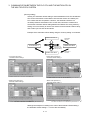
(5) The operating system software package for your application needs
By installing the operating system software for applications in the internal flash
memory of the Motion CPU, the Motion controller suitable for the machine can be
realized.
And, it also can correspond with the function improvement of the software
package.
(a) Conveyor assembly use (SV13)
Offer liner interpolation, circular interpolation, helical interpolation, constantspeed control, speed control, fixed-pitch feed and etc. by the dedicated
servo instruction. Ideal for use in conveyors and assembly machines.
1-4
1 OVERVIEW
(b) Automatic machinery use (SV22)
Provides synchronous control and offers electronic cam control by
mechanical support language. Ideal for use in automatic machinery.
(c) Machine tool peripheral use (SV43)
Offer liner interpolation, circular interpolation, helical interpolation, constantspeed positioning and etc. by the EIA language (G-code). Ideal for use in
machine tool peripheral.
1-5
1 OVERVIEW
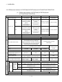
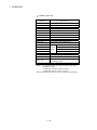
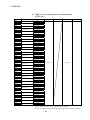
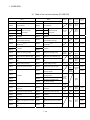
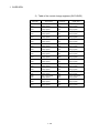
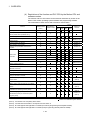
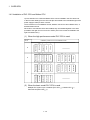
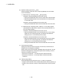
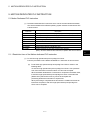
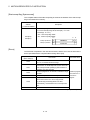
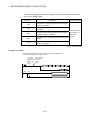
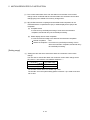
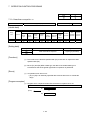
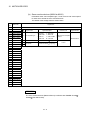
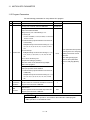
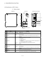
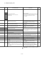
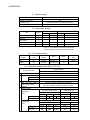
1.2.2 Basic specifications of Q173CPU(N)/Q172CPU(N)
(1) Module specifications
Item
Q173CPUN
Q173CPUN-T
Q173CPU
Q172CPUN
Q172CPUN-T
Q172CPU
Teaching unit
——
Usable
——
——
Usable
——
Internal current
consumption(5VDC) [A]
1.25
1.56 (Note)
1.75
1.14
1.45 (Note)
1.62
Mass [kg]
0.23
0.24
0.22
0.22
0.23
Exterior dimensions
[mm(inch)]
98(3.86)(H)
27.4(1.08)(W)
114.3(4.50)(D)
118(4.65)(H)
27.4(1.08)(W)
89.3(3.52)(D)
98(3.86)(H)
27.4(1.08)(W)
114.3(4.50)(D)
0.21
118(4.65)(H)
27.4(1.08)(W)
89.3(3.52)(D)
(Note) : Current consumption 0.26[A] of the teaching unit is included.
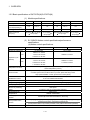
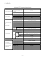
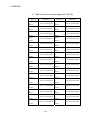
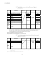
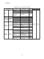
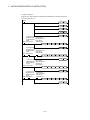
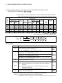
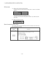
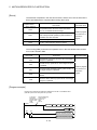
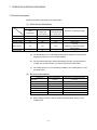
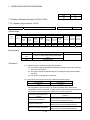
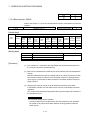
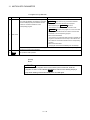
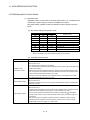
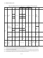
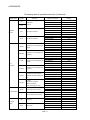
(2) SV13/SV22 Motion control specifications/performance
specifications
(a) Motion control specifications
Item
Q173CPUN(-T)
Number of control axes
Q173CPU
Q172CPUN(-T)
Up to 32 axes
Q172CPU
Up to 8 axes
0.88ms/ 1 to 8 axes
SV13
1.77ms/ 9 to 16 axes
0.88ms/1 to 8 axes
3.55ms/17 to 32 axes
Operation cycle
0.88ms/ 1 to 4 axes
(default)
SV22
1.77ms/ 5 to 12 axes
0.88ms/1 to 4 axes
3.55ms/13 to 24 axes
1.77ms/5 to 8 axes
7.11ms/25 to 32 axes
Interpolation functions
Linear interpolation (Up to 4 axes), Circular interpolation (2 axes),
Helical interpolation (3 axes)
PTP(Point to Point) control, Speed control, Speed-position control, Fixed-pitch feed,
Control modes
Constant speed control, Position follow-up control, Speed switching control,
High-speed oscillation control, Synchronous control (SV22)
Acceleration/
deceleration control
Compensation
Automatic trapezoidal acceleration/deceleration,
S-curve acceleration/deceleration
Backlash compensation, Electronic gear
Programming language
Motion SFC, Dedicated instruction, Mechanical support language (SV22)
Servo program capacity
14k steps
Number of positioning
points
3200 points
(Positioning data can be designated indirectly)
Programming tool
Peripheral I/F
Teaching operation
function
Home position return
function
IBM PC/AT
USB/RS-232/SSCNET
Provided (Q173CPUN-T/Q172CPUN-T, SV13 use)
Proximity dog type (2 types), Count type (3 types), Data set type (2 types), Dog cradle type,
Stopper type (2 types), Limit switch combined type
(Home position return re-try function provided, home position shift function provided)
JOG operation function
Provided
1-6
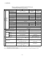
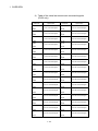
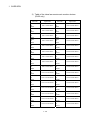
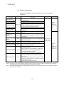
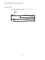
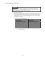
1 OVERVIEW
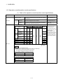
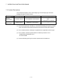
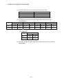
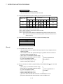
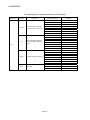
Motion control specifications (continued)
Item
Q173CPUN(-T)
Q173CPU
Manual pulse generator
operation function
Q172CPU
Possible to connect 3 modules
operation function
Synchronous encoder
Q172CPUN(-T)
Possible to connect 12 modules
Possible to connect 8 modules
M-code output function provided
M-code function
M-code completion wait function provided
Limit switch output
Number of output points 32 points
function
Watch data: Motion control data/Word device
Made compatible by setting battery to servo amplifier.
Absolute position system
(Possible to select the absolute data method or incremental method for each axis)
(Note) : When the vector inverter is used, only the increment method.
Number of SSCNET I/F
Motion related interface
module
5CH
(Note-1)
2CH
Q172LX : 4 modules usable
Q172LX : 1 module usable
Q172EX : 6 modules usable
Q173PX : 4 modules usable
Q172EX : 4 modules usable
(Note-2)
Q173PX : 3 modules usable
(Note-2)
(Note-1) : Use the Dividing unit(Q173DV) or dividing cable(Q173J2B CBL M/Q173HB CBL M).
(Note-2) : When using the incremental synchronous encoder (SV22 use), you can use avobe number of modules.
When connecting the manual pulse generator, you can use only 1 module.
1-7
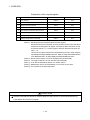
1 OVERVIEW
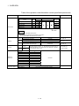
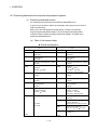
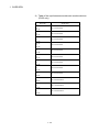
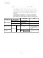
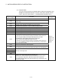
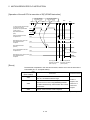
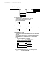
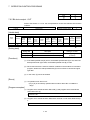
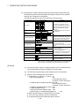
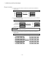
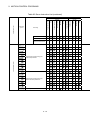
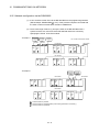
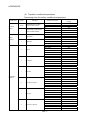
(b) Motion SFC Performance Specifications
Item
Q173CPU(N)/Q172CPU(N)
Code total
(Motion SFC chart+ Operation control
Motion SFC program capacity + Transition)
Text total
(Operation control + Transition)
224k bytes
Number of Motion SFC programs
256 (No.0 to 255)
Motion SFC chart size/program
Motion SFC program
Up to 64k bytes (Included Motion SFC chart comments)
Number of Motion SFC steps/program
255
Number of parallel branches/branch
255
Up to 4 levels
Number of operation control programs
Number of transition programs
Up to approx. 64k bytes (32766 steps)
Number of blocks(line)/program
Up to 8192 blocks (in the case of 4 steps(min)/blocks)
Number of characters/block (line)
Up to 128 (comment included)
Number of operand/block
Up to 64 (operand: constants, word device, bit devices)
( ) nesting/block
Up to 32 levels
Descriptive
expression Transition program
Calculation expression/bit conditional expression
Calculation expression/bit conditional expression/
comparison conditional expression
Number of multi executed programs
Number of multi active steps
Up to 256
Up to 256 steps/all programs
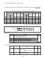
Normal task
Executed in motion main cycle
Event task Fixed cycle
(Execution
Executed
External
can be
task
interrupt
masked.)
PLC interrupt
Executed in fixed cycle
(0.88ms, 1.77ms, 3.55ms, 7.11ms, 14.2ms)
Executed when input ON is set among interrupt module QI60
(16 points).
Executed with interrupt instruction (S(P).GINT) from PLC CPU.
Executed when input ON is set among interrupt module QI60
(16 points).
NMI task
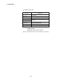
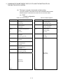
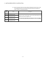
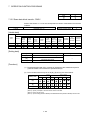
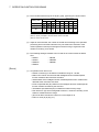
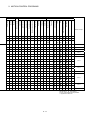
Number of I/O points (X/Y)
8192 points
Number of real I/O points (PX/PY)
Number of devices
(Device In the Motion CPU
only)
(Included the positioning
dedicated device)
4096 with F(Once execution type) and FS(Scan execution type)
combined. (F/FS0 to F/FS4095)
4096(G0 to G4095)
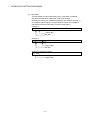
Code size/program
Operation control program
Execute specification
Up to 4094 steps
Number of selective branches/branch
Parallel branch nesting
Operation control program
(F/FS)
/
Transition program
(G)
287k bytes
256 points
Internal relays
(M)
Latch relays
(L)
Total (M + L) : 8192 points
Link relays
(B)
8192 points
Annunciators
(F)
2048 points
Special relays
(M)
256 points
Data registers
(D)
8192 points
Link registers
(W)
8192 points
Special registers (D)
256 points
Motion registers (#)
8192 points
1 point (888µs)
Coasting timers (FT)
1-8
1 OVERVIEW
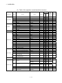
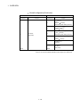
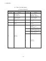
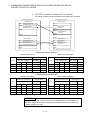
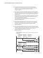
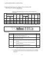
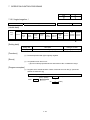
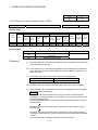
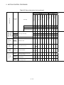
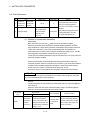
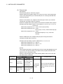
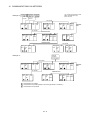
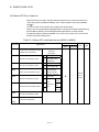
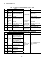
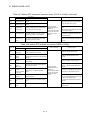
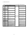
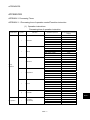
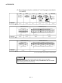
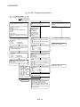
1.2.3 Operation control/transition control specifications
(1) Table of the operation control/transition control specifications
Item
Specifications
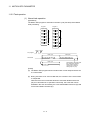
D100+1,SIN(D100), etc.
Bit conditional
expression
Returns a true or false result.
Expression for judging ON or OFF of bit device.
M0, !M0, M1*M0,
(M1+M2)*(!M3+M4), etc.
Comparison
conditional
expression
Expressions for comparing indirectly specified data and calculation
expressions using constants and word devices.
D100==100
D10<D102+D10, etc.
Calculation expression
Expression
Conditional
expression
Device
Input
Output
Bit devices
Remark
Returns a numeric result.
Expressions for calculating indirectly specified data using constants
and word devices.
Symbol
Accessibility
Read
Write
Usable tasks
Normal
Event
NMI
Description
example
Input module
non-loaded
range
X
X100
Input module
loaded range
PX
PX180
Output module
non-loaded
range
Y
Y100
Output module
loaded range
PY
PY1E0
Internal relay
M
M20
Latch relay
L
L1000
Link relay
B
B3FF
Annunciator
F
F0
Special relay
M
M9000
: usable
: unusable
CAUTION
<Restrictions on write-enabled bit devices>
1) Write to device X is allowed only within the input module non-installed range.
2) Special relay has predetermined applications in the system.
Do not perform write to other than the user setting device.
(Note) : SET/RST is disabled in the following device ranges.
SET/RST disable range
M2001 to M2032
Remark
Start accept device
(Note) : DOUT output disabled in the following device ranges.
DOUT output disable range
Designation including
M2000 to M2127
M9000 to M9255
Remark
Dedicated device
Special relay
1-9
The input X/output Y are
written with the actual input
PX/actual output PY.
It does the layput of the I/O
numbers of PX, PY by a set
up of as system.
(In the operation control
program/transition program,
automatically represented
as PX/PY according to the
system setting information.)
1 OVERVIEW
Table of the operation control/transition control specification(continued)
Item
Specifications
Devices
Word devices
Symbol
Remark
Accessibility
Read
Write
Description
example
Usable tasks
Normal
Event
NMI
Data register
D
DOL
Link register
W
W1F : F
Special register
D
D9000
Motion register
#
#0F
Coasting timer
FT
FT
: usable
: unusable
CAUTION
<Restrictions on write-enabled word devices>
1) Special register has predetermined applications in the system.
Do not perform write to other than the user-set device.
(None)
Data type
L
Read/write response
of input PX, output PY
-32768 to 32767
0 to 65535
32-bit integer type (signed)
-2147483648 to 2147483647
32-bit integer type (unsigned)
0 to 4294967295
F
64-bit floating-point type
(double precision real number type)
K
Decimal
constant
H
Hexadecimal
constant
Constant
Number of
instructions
16-bit integer type (signed)
16-bit integer type (unsigned)
IEEE format
The above data type symbol 'L' or '. (decimal point)' provided at the end
indicates the data type. The constant without the data type is regarded
as the applicable minimum type.
Binary operation
6
Bit operation
6
Sign
1
Standard function
15
Type conversion
6
Bit device status
2
Bit device control
5
Logical operation
4
Comparison operation
6
Motion dedicated function
2
Others
10
63 in total
Input response
Direct read control at instruction execution.
Output response
Direct write control at instruction execution.
1 - 10
K10, D100, etc.
2000000000, W100L, etc.
1.23, #10F, etc.
K-100, H0FFL, etc.
'K' may be omitted.
1 OVERVIEW
(2) Table of the operation control/transition instruction
Usable step
Classification
Binary operation
Bit operation
Sign
Standard function
Symbol
Function
G
Substitution
(D)=(S)
4
—
7.4.1
Addition
(S1)+(S2)
4
—
7.4.2
-
Subtraction
(S1)-(S2)
4
—
7.4.3
*
Multiplication
(S1)*(S2)
4
—
7.4.4
/
Division
(S1)/(S2)
4
—
7.4.5
%
Remainder
4
—
7.4.6
~
Bit inversion (complement)
(S1)%(S2)
~(S)
2
—
7.5.1
&
Bit logical AND
(S1)&(S2)
4
—
7.5.2
|
Bit logical OR
(S1)|(S2)
4
—
7.5.3
^
Bit exclusive OR
(S1)^(S2)
4
—
7.5.4
>>
Bit right shift
(S1)>>(S2)
4
—
7.5.5
<<
Bit left shift
(S1)<<(S2)
4
—
7.5.6
Sign inversion (complement of 2)
-(S)
2
—
7.5.7
SIN
Sine
SIN(S)
2
—
7.6.1
COS
Cosine
COS(S)
2
—
7.6.2
TAN
Tangent
TAN(S)
2
—
7.6.3
ASIN
Arcsine
ASIN(S)
2
—
7.6.4
ACOS
Arccosine
ACOS(S)
2
—
7.6.5
ATAN
Arctangent
ATAN(S)
2
—
7.6.6
SQRT
Square root
SQRT(S)
2
—
7.6.7
Natural logarithm
LN(S)
2
—
7.6.8
EXP
Exponential operation
EXP(S)
2
—
7.6.9
ABS
Absolute value
ABS(S)
2
—
7.6.10
RND
-
LN
Round-off
RND(S)
2
—
7.6.11
FIX
Round-down
FIX(S)
2
—
7.6.12
FUP
Round-up
FUP(S)
2
—
7.6.13
BIN
BCD
BIN conversion
BIN(S)
2
—
7.6.14
BCD
BIN
BCD conversion
BCD(S)
2
—
7.6.15
SHORT(S)
2
—
7.7.1
USHORT(S)
2
—
7.7.2
LONG(S)
2
—
7.7.3
ULONG(S)
2
—
7.7.4
FLOAT
Regard as signed data and convert into 64bit floating point type
FLOAT(S)
2
—
7.7.5
UFLOAT
Regard as unsigned data and convert into
64-bit floating point type
UFLOAT(S)
2
—
7.7.6
ON (normally open contact)
(S)
2
OFF (normally closed contact)
!(S)
2
SET(D)
3
—
SET(D)= (conditional
expression)
4
—
RST(D)
3
—
RST(D)=(conditional
expression)
4
—
LONG
Bit device control
F/FS
+
USHORT Convert into 16-bit integer type (unsigned)
Bit device status
Basic steps
=
SHORT Convert into 16-bit integer type (signed)
Type conversion
Format
Y/N
transition's Section of
conditional reference
expression
Convert into 32-bit integer type (signed)
ULONG Convert into 32-bit integer type (unsigned)
(None)
!
SET
Device set
RST
Device reset
7.8.1
7.8.2
7.9.1
7.9.2
DOUT
Device output
DOUT(D),(S)
4
—
7.9.3
DIN
Device input
DIN(D),(S)
4
—
7.9.4
Bit device output
OUT(D)=(conditional
expression)
4
—
7.9.5
OUT
1 - 11
1 OVERVIEW
Table of the operation control/transition instruction (continued)
Usable step
Classification
Symbol
(None)
Comparison
operation
Motion dedicated
function
Others
Format
Basic steps
F/FS
G
Logical acknowledgment
(Conditional expression)
0
7.10.1
Logical negation
!(Conditional expression)
2
7.10.2
*
Logical AND
(Conditional expression) *
(conditional expression)
4
7.10.3
+
Logical OR
(Conditional expression) +
(conditional expression)
4
7.10.4
==
Equal to
(Conditional expression) ==
(conditional expression)
4
7.11.1
!=
Not equal to
(Conditional expression) !=
(conditional expression)
4
7.11.2
<
Less than
(Conditional expression) <
(conditional expression)
4
7.11.3
<=
Less than or equal to
(Conditional expression) <=
(conditional expression)
4
7.11.4
>
More than
(Conditional expression) >
(conditional expression)
4
7.11.5
>=
More than or equal to
(Conditional expression) >=
(conditional expression)
4
7.11.6
CHGV
Speed change request
CHGV((S1),(S2))
4
—
7.12.1
CHGT
Torque limit value change request
CHGT((S1),(S2))
4
—
7.12.2
EI
Event task enable
EI
1
—
7.13.1
DI
Event task disable
DI
1
—
7.13.2
NOP
No operation
NOP
1
—
7.13.3
BMOV
Block transfer
BMOV(D),(S),(n)
6
—
7.13.4
FMOV
Same data block transfer
FMOV(D),(S),(n)
6
—
7.13.5
MULTW(D),(S),(n),(D1)
8
—
7.13.6
Read device data from shared CPU
memory of the other CPU
MULTR(D),(S1),(S2),(n)
7
—
7.13.7
Write device data to intelligent function
module/special function module.
TO(D1),(D2),(S),(n)
7
—
7.13.8
FROM
Read device data from intelligent function
module/special function module.
FROM(D),(S1),(S2),(n)
7
—
7.13.9
TIME
Time to wait
TIME(S)
7
—
7.13.10
!
Logical operation
Function
Y/N
transition's Section of
conditional reference
expression
Write device data to shared CPU memory
MULTW
of the self CPU
MULTR
TO
—
: Usable
—: Unusable
(3) Rough calculation expression of singleprogram for operation
control/transition program
2 + (1 + Total number of basic steps in 1 block
+ Number of 32-bit constants/1 block
1
+ Number of 64-bit constants/1 block
3)
Number of blocks (steps)
(1 step = 2 bytes)
1 - 12
1 OVERVIEW
1.2.4 Differences between Q173CPU(N)/Q172CPU(N) and A173UHCPU/A172SHCPUN
(1) Differences between Q173CPU(N)/Q172CPU(N) and
A173UHCPU/A172SHCPUN
Item
Q173CPU(N)
Q172CPU(N)
A173UHCPU
A172SHCPUN
Up to 32 axes
Up to 8 axes
Up to 32 axes
Up to 8 axes
SV13
0.88ms/1 to 8 axes
1.77ms/9 to 16 axes
3.55ms/17 to 32 axes
(Default)
(It can be set up by
the parameters.)
0.88ms/1 to 8 axes
(Default)
(It can be set up by
the parameters.)
3.55ms/1 to 20 axes
7.11ms/21 to 32 axes
3.55ms/1 to 8 axes
SV22
0.88ms/1 to 4 axes
1.77ms/5 to 12 axes
3.55ms/13 to 24 axes
7.11ms/25 to 32 axes
(Default)
(It can be set up by
the parameters.)
0.88ms/1 to 4 axes
1.77ms/5 to 8 axes
(Default)
(It can be set up by
the parameters.)
3.55ms/1 to 12 axes
7.11ms/13 to 24 axes
14.2ms/25 to 32 axes
3.55 ms/1 to 8 axes
Number of control axes
Operation cycle
Motion control
Servo program capacity
14k steps
Number of positioning points
Programming tool
IBM PC/AT, A31TU-D
PC9800 series, IBM PC/AT, A30TU, A31TU
Peripheral devices I/F
USB/RS-232/SSCNET
RS-422/SSCNET
Proximity dog type(2 types), Count type(3 types),
Data set type(2 types), Dog cradle type,
Stopper type(2 types), Limit switch conbined type
(Home position return retry function provided,
Home position shift function provided)
Proximity dog type, count type,
data set type 1
Home position return function
Manual pulse generator operation
function
Syncronous encoder operation
function
Limit switch output function
Possible to connect 3 modules
Possible to connect
12 modules
Possible to connect
8 modules
5CH (Note-1)
2CH
Number of Motion related modules
Q172LX : 4 modules
Q172LX : 1 module
Q172EX : 6 modules
Q172EX : 4 modules
Q173PX : 4 modules (Note-2)
Q173PX : 3 modules (Note-2)
Normal task
Execute specification
Possible to connect
1 module
4CH
2CH
8 slots
2 slots
A172SENC : 4 modules
A172SENC : 1 module
Up to 64 slots
(Up to 7 extension bases of the Q series)
Number of motion slots
Event task
(Execution
Excuted can be
masked.)
task
Possible to connect
4 modules
Output points : 32points, watch data : motion control data/word device
Number of SSCNET Interfaces
(Included SSCNET interface 1CH to
the parsonal computer)
Motion SFC
13k steps
3200 points/axis (Positioning data can be designated indirectly.)
Executed in motion main cycle
Fixed
cycle
Executed in fixed cycle
(0.88ms, 1.77ms, 3.55ms, 7.11ms, 14.2ms)
Executed in fixed cycle
(1.77ms, 3.55ms, 7.11ms, 14.2ms)
External
interrupt
Executed when input on is set among interrupt
module(QI60) 16 points.
Executed when input on is set among
interrupt module(A1SI61) 16 points.
PLC
interrupt
Executed with interrupt instruction (GINT) from
PLC CPU.
Executed when 1 interrupt point is provided
from PLC CPU.
Executed when input on is set among interrupt
module(QI60) 16 points.
Executed when input on is set among
interrupt module(A1SI61) 16 points.
NMI task
Number of I/O (X/Y) points
8192 points
Number of real I/O (PX/PY) points
Total 256 points
1 - 13
2048 points
1 OVERVIEW
Differences Between Q173CPU(N)/Q172CPU(N) and
A173UHCPU/A172SHCPUN(continued)
Item
Internal relays (M)
Motion SFC
Latch relays (L)
Number of
Devices
(internal
motion
CPU only)
Q172CPU(N)
Total M+L : 8192 points
A173UHCPU
A172SHCPUN
Total M+L(S) :
8192 points
Total M+L(S) :
2048 points
Link relays (B)
8192 points
1024 points
Annunciators (F)
2048 points
256 points
Timer contacts (TT)
—
2048 points
256 points
Timer coils (TC)
—
2048 points
256 points
Counter contacts (CT)
—
1024 points
256 points
Counter coils (CC)
—
1024 points
256 points
Special relays (M)
256 points
Data registers (D)
8192 points
1024 points
Link registers (W)
8192 points
1024 points
Currnet value timers (T)
—
2048 points
256 points
Currnet value counters (C)
—
1024 points
256 points
Special registers (D)
256 points
Motion registers (#)
8192 points
Coasting timer (FT)
1 point (888µs)
Device memory
Data exchange of PCPU and SCPU
Number of pulses per
revolutions
Fixed
Amount of pulses per
parameters revolutions
Others
Q173CPU(N)
Magnification
PLC ready flag (M2000)
Forced stop input
Back-up battery for internal memory
Independence
Commonness
The data exchange method by automatic refresh
between the multiple CPU's.
The direct data exchange method which
made a device memory 2 port memory.
1 to 2147483647[PLS]
1 to 65535[PLS]
In the case of the unit setup [PLS].
1 to 2147483647[PLS]
In the case of the unit setup [PLS].
1 to 65535[PLS]
—
1 time, 10 times,
100 times, 1000 times
RUN),
M2000 turn it on with switch (STOP
or M2000 turn it on when both of switch RUN and
setting register is set "1".
M2000 turn on by PLC program
An optional bit device(PX, M) is specified in the
parameter. (Emergency stop terminals of the
servo amplifiers can be used.)
Emergency stop of the CPU base unit.
(Forced stop terminals of the servo amplifiers
cannot be used.)
Internal rechargeable battery
(Set the external battery (A6BAT/MR-BAT) if
continuous power off time is longer for 1 month or
more.) (Note-3)
A6BAT/MR-BAT
(Note-1) : Use the Dividing unit (Q173DV) or dividing cable (Q173J2B CBL M/Q173HB CBL M).
(Note-2) : When using the incremental synchronous encoder (SV22 use), you can use above number of modules. When connecting the Manual
pulse generator, you can use only 1 module.
(Note-3) : When adding the external battery (A6BAT/MR-BAT), Q173DV (Q173CPU(N) use.), or Q170BAT (Q172CPU(N) use.) is used.
1 - 14
1 OVERVIEW
1.2.5 Positioning dedicated devices/special relays/special registers
(1) Positioning dedicated devices
The following section describes the positioning dedicated devices.
A range of up to 32 axes is valid in Q173CPU(N), and a range of up to 8 axes is
valid in Q172CPU(N).
Refer to the "Q173CPU(N)/Q172CPU(N) Motion controller (SV13/SV22)
Programming Manual (REAL MODE)", "Q173CPU(N)/Q172CPU(N) Motion
controller (SV22) Programming Manual (VIRTUAL MODE)" for details of the
positioning dedicated devices.
(a) Table of the internal relays
Overall configuration
SV13
Device No.
M0
to
M2000
to
M2320
to
SV22
Purpose
M0
User device
(2000 points)
to
M2000
Common device
(320 points)
to
Special relay allocated device (Status) M2320
(80 points)
to
M2400
to
M3040
to
M3072
to
M3136
to
M2400
Axis status
(20 points
32 axes)
to
M3040
Unusable
to
Common device (Command signal)
(64 points)
M3072
Special relay allocated device
(Command signal)
(64 points)
M3136
M3200
to
Device No.
to
to
M3200
Axis command signal
(20 points
32 axes)
to
M3840
M3840
to
M4000
to
to
User device
(960 points)
M4640
to
Purpose
User device
(2000 points)
Common device
(320 points)
Special relay allocated device (Status)
(80 points)
Axis status
(20 points
32 axes)
Real mode……Each axis
Virtual mode….Output module
Unusable
Common device (Command signal)
(64 points)
Special relay allocated device
(Command signal)
(64 points)
Axis command signal
(20 points
32 axes)
Real mode……Each axis
Virtual mode….Output module
Unusable (Note-1)
(160 points)
Virtual servomotor axis status (Note-1,2)
(20 points
32 axes)
(Mechanical system setting axis only)
Synchronous encoder axis
status (Note-2) (4 points
12 axes)
M4688
to
M4799
M4799
1 - 15
Unusable (Note-1)
1 OVERVIEW
Overall configuration(Continued)
SV13
Device No.
SV22
Purpose
M4800
Device No.
M4800
to
M5440
to
M5488
to
User device
(3392 points)
to
M5520
to
M5584
to
Purpose
Virtual servomotor axis command
signal (Note-1, 2)
(20 points
32 axes)
(Mechanical system setting axis only)
Synchronous encoder axis
command signal (Note-2)
(4 points
12 axes)
Cam axis command signal (Note-1, 2)
(1 point
32 axes)
(Mechanical system setting axis only)
Smoothing clutch complete signal
(Note-1, 2)
(2 points
32 axes)
Unusable (Note-1)
(16 points)
M5600
to
M8191
M8191
User device
(2592 points)
(Note-1) : It can be used as an user device in the SV22 real mode only.
(Note-2) : Do not set the M4000 to M5599 as a latch range in the virtual mode.
1 - 16
1 OVERVIEW
MEMO
1 - 17
1 OVERVIEW
1) Table of the axis statuses (SV13/SV22)
Device No.
Signal name
Device No.
Signal name
M2400
to
M2419
Axis 1 status
M2720
to
M2739
Axis 17 status
M2420
to
M2439
Axis 2 status
M2740
to
M2759
Axis 18 status
M2440
to
M2459
Axis 3 status
M2760
to
M2779
Axis 19 status
M2460
to
M2479
Axis 4 status
M2780
to
M2799
Axis 20 status
M2480
to
M2499
Axis 5 status
M2800
to
M2819
Axis 21 status
M2500
to
M2519
Axis 6 status
M2820
to
M2839
Axis 22 status
M2520
to
M2539
Axis 7 status
M2840
to
M2859
Axis 23 status
M2540
to
M2559
Axis 8 status
M2860
to
M2879
Axis 24 status
M2560
to
M2579
Axis 9 status
M2880
to
M2899
Axis 25 status
M2580
to
M2599
Axis 10 status
M2900
to
M2919
Axis 26 status
M2600
to
M2619
Axis 11 status
M2920
to
M2939
Axis 27 status
M2620
to
M2639
Axis 12 status
M2940
to
M2959
Axis 28 status
M2640
to
M2659
Axis 13 status
M2960
to
M2979
Axis 29 status
M2660
to
M2679
Axis 14 status
M2980
to
M2999
Axis 30 status
M2680
to
M2699
Axis 15 status
M3000
to
M3019
Axis 31 status
M2700
to
M2719
Axis 16 status
M3020
to
M3039
Axis 32 status
1 - 18
1 OVERVIEW
Detailes of each axis
Device No.
Signal name
M2400 + 20n
Positioning start complete
M2401 + 20n
Positioning complete
M2402 + 20n
In-position
M2403 + 20n
Command in-position
M2404 + 20n
Speed controlling
M2405 + 20n
Speed/position switching latch signal
M2406 + 20n
Zero pass signal
M2407 + 20n
Error detection signal
M2408 + 20n
Servo error detection signal
M2409 + 20n
Home position return request signal
M2410 + 20n
Home position return completion signal
M2411 + 20n
M2412 + 20n
M2413 + 20n
FLS signal
External
signals
STOP signal
DOG/CHANGE signal
M2414 + 20n
M2415 + 20n
RLS signal
Servo ready signal
M2416 + 20n
Torque limiting signal
M2417 + 20n
Unusable
M2418 + 20n
Virtual mode continuation operation disable
warning signal (SV22)
M2419 + 20n
M-code outputting signal
(Note-1) : "n" in the above device No. shows the numerical value which
correspond to axis No.
Q173CPU(N) : Axis No.1 to No.32 (n=0 to 31)
Q172CPU(N) : Axis No.1 to No.8 (n=0 to 7)
(Note-2) : Device area of 9 axes or more is unusable in the Q172CPU(N).
1 - 19
1 OVERVIEW
2) Table of the axis command signals (SV13/SV22)
Device No.
Signal name
Device No.
Signal name
M3200
to
M3219
Axis 1 command signal
M3520
to
M3539
Axis 17 command signal
M3220
to
M3239
Axis 2 command signal
M3540
to
M3559
Axis 18 command signal
M3240
to
M3259
Axis 3 command signal
M3560
to
M3579
Axis 19 command signal
M3260
to
M3279
Axis 4 command signal
M3580
to
M3599
Axis 20 command signal
M3280
to
M3299
Axis 5 command signal
M3600
to
M3619
Axis 21 command signal
M3300
to
M3319
Axis 6 command signal
M3620
to
M3639
Axis 22 command signal
M3320
to
M3339
Axis 7 command signal
M3640
to
M3659
Axis 23 command signal
M3340
to
M3359
Axis 8 command signal
M3660
to
M3679
Axis 24 command signal
M3360
to
M3379
Axis 9 command signal
M3680
to
M3699
Axis 25 command signal
M3380
to
M3399
Axis 10 command signal
M3700
to
M3719
Axis 26 command signal
M3400
to
M3419
Axis 11 command signal
M3720
to
M3739
Axis 27 command signal
M3420
to
M3439
Axis 12 command signal
M3740
to
M3759
Axis 28 command signal
M3440
to
M3459
Axis 13 command signal
M3760
to
M3779
Axis 29 command signal
M3460
to
M3479
Axis 14 command signal
M3780
to
M3799
Axis 30 command signal
M3480
to
M3499
Axis 15 command signal
M3800
to
M3819
Axis 31 command signal
M3500
to
M3519
Axis 16 command signal
M3820
to
M3839
Axis 32 command signal
1 - 20
1 OVERVIEW
Detailes of each axis
Device No.
SV13
SV22
M3200 + 20n
Stop command
Stop command
M3201 + 20n
Rapid stop command
Rapid stop command
M3202 + 20n
Forward rotation JOG start
command
Forward rotation JOG start command
M3203 + 20n
Reverse rotation JOG start
command
Reverse rotation JOG start comannd
M3204 + 20n
Complete signal OFF command
Complete signal OFF command
M3205 + 20n
Speed/position switching enable
command
Speed/position switching enable
comannd
M3206 + 20n
Unusable
Unusable
M3207 + 20n
Error reset command
Error reset command
M3208 + 20n
Servo error reset command
Servo error reset command
M3209 + 20n
External stop input disable at start
command
External stop input disable at start
command
Unusable
Unusable
Feed current value update request
command
Feed current value update request
command
M3210 + 20n
M3211 + 20n
M3212 + 20n
M3213 + 20n
Unusable
M3214 + 20n
Address clutch reference setting
command
Cam reference position setting
command
M3215 + 20n
Servo OFF command
Servo OFF command
M3216 + 20n
Gain changing command
Gain changing command
Unusable
Unusable
FIN signal
FIN signal
M3217 + 20n
M3218 + 20n
M3219 + 20n
(Note-1) : "n" in the above device No. shows the numerical value which correspond to axis No.
Q173CPU(N) : Axis No.1 to No.32 (n=0 to 31)
Q172CPU(N) : Axis No.1 to No.8 (n=0 to 7)
(Note-2) : Device area of 9 axes or more is unusable in the Q172CPU(N).
1 - 21
1 OVERVIEW
3) Table of the virtual servomotor axis statuses (SV22 only)
Device No.
Signal name
Device No.
Signal name
M4000
to
M4019
Axis 1 status
M4320
to
M4339
Axis 17 status
M4020
to
M4039
Axis 2 status
M4340
to
M4359
Axis 18 status
M4040
to
M4059
Axis 3 status
M4360
to
M4379
Axis 19 status
M4060
to
M4079
Axis 4 status
M4380
to
M4399
Axis 20 status
M4080
to
M4099
Axis 5 status
M4400
to
M4419
Axis 21 status
M4100
to
M4119
Axis 6 status
M4420
to
M4439
Axis 22 status
M4120
to
M4139
Axis 7 status
M4440
to
M4459
Axis 23 status
M4140
to
M4159
Axis 8 status
M4460
to
M4479
Axis 24 status
M4160
to
M4179
Axis 9 status
M4480
to
M4499
Axis 25 status
M4180
to
M4199
Axis 10 status
M4500
to
M4519
Axis 26 status
M4200
to
M4219
Axis 11 status
M4520
to
M4539
Axis 27 status
M4220
to
M4239
Axis 12 status
M4540
to
M4559
Axis 28 status
M4240
to
M4259
Axis 13 status
M4560
to
M4579
Axis 29 status
M4260
to
M4279
Axis 14 status
M4580
to
M4599
Axis 30 status
M4280
to
M4299
Axis 15 status
M4600
to
M4619
Axis 31 status
M4300
to
M4319
Axis 16 status
M4620
to
M4639
Axis 32 status
1 - 22
1 OVERVIEW
Detailes of each axis
Device No.
Signal name
M4000 + 20n
Positioning start complete
M4001 + 20n
Positioning complete
M4002 + 20n
Unusable
M4003 + 20n
Command in-position
M4004 + 20n
Speed controlling
M4005 + 20n
M4006 + 20n
M4007 + 20n
Unusable
Error detection
M4008 + 20n
M4009 + 20n
M4010 + 20n
M4011 + 20n
M4012 + 20n
M4013 + 20n
Unusable
M4014 + 20n
M4015 + 20n
M4016 + 20n
M4017 + 20n
M4018 + 20n
M4019 + 20n
M-code outputting signal
(Note-1) : "n" in the above device No. shows the numerical value which
correspond to axis No.
Q173CPU(N) : Axis No.1 to No.32 (n=0 to 31)
Q172CPU(N) : Axis No.1 to No.8 (n=0 to 7)
(Note-2) : The unused axis areas in the mechanical system program can be used as an
user device.
1 - 23
1 OVERVIEW
4) Table of the virtual servomotor axis command signals
(SV22 only)
Device No.
Signal name
Device No.
Signal name
M4800
to
M4819
Axis 1 command signal
M5120
to
M5139
Axis 17 command signal
M4820
to
M4839
Axis 2 command signal
M5140
to
M5159
Axis 18 command signal
M4840
to
M4859
Axis 3 command signal
M5160
to
M5179
Axis 19 command signal
M4860
to
M4879
Axis 4 command signal
M5180
to
M5199
Axis 20 command signal
M4880
to
M4899
Axis 5 command signal
M5200
to
M5219
Axis 21 command signal
M4900
to
M4919
Axis 6 command signal
M5220
to
M5239
Axis 22 command signal
M4920
to
M4939
Axis 7 command signal
M5240
to
M5259
Axis 23 command signal
M4940
to
M4959
Axis 8 command signal
M5260
to
M5279
Axis 24 command signal
M4960
to
M4979
Axis 9 command signal
M5280
to
M5299
Axis 25 command signal
M4980
to
M4999
Axis 10 command signal
M5300
to
M5319
Axis 26 command signal
M5000
to
M5019
Axis 11 command signal
M5320
to
M5339
Axis 27 command signal
M5020
to
M5039
Axis 12 command signal
M5340
to
M5359
Axis 28 command signal
M5040
to
M5059
Axis 13 command signal
M5360
to
M5379
Axis 29 command signal
M5060
to
M5079
Axis 14 command signal
M5380
to
M5399
Axis 30 command signal
M5080
to
M5099
Axis 15 command signal
M5400
to
M5419
Axis 31 command signal
M5100
to
M5119
Axis 16 command signal
M5420
to
M5439
Axis 32 command signal
1 - 24
1 OVERVIEW
Detailes of each axis
Device No.
Signal name
M4800 + 20n
Stop command
M4801 + 20n
Rapid stop command
M4802 + 20n
Forward rotation JOG start command
M4803 + 20n
Reverse rotation JOG start command
M4804 + 20n
Complete signal OFF command
M4805 + 20n
Unusable
M4806 + 20n
M4807 + 20n
Error reset command
M4808 + 20n
Unusable
M4809 + 20n
External stop input disable at start command
M4810 + 20n
M4811 + 20n
M4812 + 20n
M4813 + 20n
Unusable
M4814 + 20n
M4815 + 20n
M4816 + 20n
M4817 + 20n
M4818 + 20n
M4819 + 20n
FIN signal
(Note-1) : "n" in the above device No. shows the numerical value which
correspond to axis No.
Q173CPU(N) : Axis No.1 to No.32 (n=0 to 31)
Q172CPU(N) : Axis No.1 to No.8 (n=0 to 7)
(Note-2) : The unused axis areas in the mechanical system program can be used as an
user device.
1 - 25
1 OVERVIEW
5) Table of the synchronous encoder axis statuses
(SV22 only)
Device No.
M4640
M4641
M4642
M4643
M4644
M4645
M4646
M4647
M4648
M4649
M4650
M4651
M4652
M4653
M4654
M4655
M4656
M4657
M4658
M4659
M4660
M4661
M4662
M4663
M4664
M4665
M4666
M4667
M4668
M4669
M4670
M4671
M4672
M4673
M4674
M4675
M4676
M4677
M4678
M4679
M4680
M4681
M4682
M4683
M4684
M4685
M4686
M4687
Signal name
Axis 1
Axis 2
Axis 3
Axis 4
Axis 5
Axis 6
Axis 7
Axis 8
Axis 9
Axis 10
Axis 11
Axis 12
Error detection
External signal TREN
Virtual mode continuation operation disable warning
Unusable
Error detection
External signal TREN
Virtual mode continuation operation disable warning
Unusable
Error detection
External signal TREN
Virtual mode continuation operation disable warning
Unusable
Error detection
External signal TREN
Virtual mode continuation operation disable warning
Unusable
Error detection
External signal TREN
Virtual mode continuation operation disable warning
Unusable
Error detection
External signal TREN
Virtual mode continuation operation disable warning
Unusable
Error detection
External signal TREN
Virtual mode continuation operation disable warning
Unusable
Error detection
External signal TREN
Virtual mode continuation operation disable warning
Unusable
Error detection
External signal TREN
Virtual mode continuation operation disable warning
Unusable
Error detection
External signal TREN
Virtual mode continuation operation disable warning
Unusable
Error detection
External signal TREN
Virtual mode continuation operation disable warning
Unusable
Error detection
External signal TREN
Virtual mode continuation operation disable warning
Unusable
(Note-1) : The range of axis No.1 to 8 is valid in the Q172CPU(N).
(Note-2) : Device area of 9 axes or more is unusable in the Q172CPU(N).
1 - 26
1 OVERVIEW
6) Table of the syncronous encoder axis command signals
(SV22 only)
Device No.
M5440
M5441
M5442
M5443
M5444
M5445
M5446
M5447
M5448
M5449
M5450
M5451
M5452
M5453
M5454
M5455
M5456
M5457
M5458
M5459
M5460
M5461
M5462
M5463
M5464
M5465
M5466
M5467
M5468
M5469
M5470
M5471
M5472
M5473
M5474
M5475
M5476
M5477
M5478
M5479
M5480
M5481
M5482
M5483
M5484
M5485
M5486
M5487
Signal name
Axis 1
Axis 2
Axis 3
Axis 4
Axis 5
Axis 6
Axis 7
Axis 8
Axis 9
Axis 10
Axis 11
Axis 12
Error reset
Unusable
Unusable
Unusable
Error reset
Unusable
Unusable
Unusable
Error reset
Unusable
Unusable
Unusable
Error reset
Unusable
Unusable
Unusable
Error reset
Unusable
Unusable
Unusable
Error reset
Unusable
Unusable
Unusable
Error reset
Unusable
Unusable
Unusable
Error reset
Unusable
Unusable
Unusable
Error reset
Unusable
Unusable
Unusable
Error reset
Unusable
Unusable
Unusable
Error reset
Unusable
Unusable
Unusable
Error reset
Unusable
Unusable
Unusable
(Note-1) : The range of axis No.1 to 8 is valid in the Q172CPU(N).
(Note-2) : Device area of 9 axes or more is unusable in the Q172CPU(N).
1 - 27
1 OVERVIEW
7) Table of the cam axis command signals (SV22 only)
Device No.
Signal name
M5488
Axis 1 cam/ballscrew switching
M5489
Axis 2 cam/ballscrew switching
M5490
Axis 3 cam/ballscrew switching
M5491
Axis 4 cam/ballscrew switching
M5492
Axis 5 cam/ballscrew switching
M5493
Axis 6 cam/ballscrew switching
M5494
Axis 7 cam/ballscrew switching
M5495
Axis 8 cam/ballscrew switching
M5496
Axis 9 cam/ballscrew switching
M5497
Axis 10 cam/ballscrew switching
M5498
Axis 11 cam/ballscrew switching
M5499
Axis 12 cam/ballscrew switching
M5500
Axis 13 cam/ballscrew switching
M5501
Axis 14 cam/ballscrew switching
M5502
Axis 15 cam/ballscrew switching
M5503
Axis 16 cam/ballscrew switching
M5504
Axis 17 cam/ballscrew switching
M5505
Axis 18 cam/ballscrew switching
M5506
Axis 19 cam/ballscrew switching
M5507
Axis 20 cam/ballscrew switching
M5508
Axis 21 cam/ballscrew switching
M5509
Axis 22 cam/ballscrew switching
M5510
Axis 23 cam/ballscrew switching
M5511
Axis 24 cam/ballscrew switching
M5512
Axis 25 cam/ballscrew switching
M5513
Axis 26 cam/ballscrew switching
M5514
Axis 27 cam/ballscrew switching
M5515
Axis 28 cam/ballscrew switching
M5516
Axis 29 cam/ballscrew switching
M5517
Axis 30 cam/ballscrew switching
M5518
Axis 31 cam/ballscrew switching
M5519
Axis 32 cam/ballscrew changing
(Note-1) : The range of axis No.1 to 8 is valid in the Q172CPU(N).
(Note-2) : Device area of 9 axes or more is unusable in the Q172CPU(N).
(Note-3) : The unused aixs areas in the cam axis command signal can be used as an user
device.
1 - 28
1 OVERVIEW
8) Table of the smoothing clutch complete signals
(SV22 only)
Device No.
M5520
M5521
M5522
M5523
M5524
M5525
M5526
M5527
M5528
M5529
M5530
M5531
M5532
M5533
M5534
M5535
M5536
M5537
M5538
M5539
M5540
M5541
M5542
M5543
M5544
M5545
M5546
M5547
M5548
M5549
M5550
M5551
M5552
M5553
M5554
M5555
M5556
M5557
M5558
M5559
M5560
M5561
M5562
M5563
M5564
M5565
M5566
M5567
M5568
M5569
M5570
M5571
M5572
M5573
M5574
M5575
M5576
M5577
M5578
M5579
M5580
M5581
M5582
M5583
Signal name
Output axis 1
Output axis 2
Output axis 3
Output axis 4
Output axis 5
Output axis 6
Output axis 7
Output axis 8
Output axis 9
Output axis 10
Output axis 11
Output axis 12
Output axis 13
Output axis 14
Output axis 15
Output axis 16
Output axis 17
Output axis 18
Output axis 19
Output axis 20
Output axis 21
Output axis 22
Output axis 23
Output axis 24
Output axis 25
Output axis 26
Output axis 27
Output axis 28
Output axis 29
Output axis 30
Output axis 31
Output axis 32
Refresh cycle
Fetch cycle
Signal direction
Remark
Main shaft side
Auxiliary input side
Main shaft side
Auxiliary input side
Main shaft side
Auxiliary input side
Main shaft side
Auxiliary input side
Main shaft side
Auxiliary input side
Main shaft side
Auxiliary input side
Main shaft side
Auxiliary input side
Main shaft side
Auxiliary input side
Main shaft side
Auxiliary input side
Main shaft side
Auxiliary input side
Main shaft side
Auxiliary input side
Main shaft side
Auxiliary input side
Main shaft side
Auxiliary input side
Main shaft side
Auxiliary input side
Main shaft side
Auxiliary input side
Main shaft side
Auxiliary input side
Main shaft side
Operation cycle
Status signal
Auxiliary input side
Main shaft side
Auxiliary input side
Main shaft side
Auxiliary input side
Main shaft side
Auxiliary input side
Main shaft side
Auxiliary input side
Main shaft side
Auxiliary input side
Main shaft side
Auxiliary input side
Main shaft side
Auxiliary input side
Main shaft side
Auxiliary input side
Main shaft side
Auxiliary input side
Main shaft side
Auxiliary input side
Main shaft side
Auxiliary input side
Main shaft side
Auxiliary input side
Main shaft side
Auxiliary input side
Main shaft side
Auxiliary input side
Main shaft side
Auxiliary input side
(Note-1) : The range of axis No.1 to 8 is valid in the Q172CPU(N).
(Note-2) : Device area of 9 axes or more is unusable in the Q172CPU(N).
(Note-3) : The unused aixs areas in the mechanical system program can be used as an user device.
1 - 29
1 OVERVIEW
9) Table of the common devices (SV13/SV22)
SV13
Device No.
Signal name
SV22
Device No.
Signal name
M2000
PLC ready flag
M2000
PLC ready flag
M2001
Axis1
M2001
Axis1
to
to
Start accept flag
(32 points)
Start accept flag
(32 points)
to
to
M2032
Axis32
M2032
Axis32
M2033
Unusable
M2033
Unusable
M2034
Personal computer link
communication error flag
M2034
Personal computer link
communication error flag
M2035
M2036
Motion SFC error history clear
request flag
(Note-5)
Unusable
M2037
M2035
M2036
Refresh
cycle
Main
cycle
—
Unusable
—
—
(Note-1)
(Note-4)
M3072
—
Status
signal
Main
cycle
Command
signal
—
—
M3080
M2037
At debug
mode
transition
Status
signal
M2038
Motion SFC debugging flag
M2038
Motion SFC debugging flag
M2039
Motion SFC error detection flag
M2039
Motion SFC error detection flag
Immediate
M2040
Speed switching point specified
flag
M2040
Speed switcing point specified
flag
At start
M2041
System setting error flag
M2041
System setting error flag
M2042
All axes servo ON command
M2042
All axes servo ON command
M2043
Real mode/virtual mode
switching request
M2044
Real mode/virtual mode
switching status
M2045
M2045
Real mode/virtual mode
switching error detection flag
M2046
M2046
Out-of-sync warning
M2043
M2044
Command
signal
Remark
(Note-2, 3)
Operation
cycle
(Note-5)
Signal
direction
Status
signal
Operation
cycle
Motion SFC error history clear
request flag
Fetch
cycle
Unusable
M2047
Motion slot fault detection flag
M2047
Motion slot fault detection flag
M2048
JOG operation simultaneous start
command
M2048
JOG operation simultaneous start
command
M2049
All axes servo ON accept flag
M2049
All axes servo ON accept flag
M2050
Unusable
M2050
Unusable
M2051
Manual pulse generator 1 enable
flag
M2051
Manual pulse generator 1 enable
flag
M2052
Manual pulse generator 2 enable
flag
M2052
Manual pulse generator 2 enable
flag
M2053
Manual pulse generator 3 enable
flag
M2053
Manual pulse generator 3 enable
flag
1 - 30
Operation
cycle
Status
signal
Command
signal
(Note-1)
M3073
Status
signal
Operation
cycle
At virtual
mode
transition
At virtual
mode
transition
Command
signal
M3074
(Note-1)
M3075
Status
signal
Operation
cycle
Main
cycle
Operation
cycle
—
Command
signal
(Note-1)
M3076
Status
signal
—
—
M3077
Main
cycle
Command
signal
(Note-1)
M3078
M3079
1 OVERVIEW
Table of the common devices (SV13/SV22) (continued)
SV13
Device No.
M2054
Signal name
Operation cycle over flag
M2055
to
Device No.
M2054
Refresh
cycle
Signal name
Fetch
cycle
Operation
cycle
Operation cycle over flag
Signal
direction
Status
signal
M2055
Unusable
to
M2060
M2061
SV22
Unusable
—
—
—
M2060
Axis 1
to
to
M2092
Axis 32
Speed changing flag
(32 axes)
M2093
M2061
Axis 1
to
to
M2092
Axis 32
Speed changing flag
(32 axes)
Status
signal
Operation
cycle
(Note-2, 3)
M2093
to
Unusable
—
—
—
M2100
to
Unusable
M2101
Axis 1
to
to
M2112
Axis 12
Synchronous encoder
current value changing
flag
(12 axes)
Status
signal
Operation
cycle
(Note-2, 3)
M2113
to
M2127
—
—
—
M2127
M2128
Axis 1
to
to
M2159
Axis 32
Automatic decelerating
flag
(32 axes)
M2160
M2128
Axis 1
to
to
M2159
Axis 32
M2160
M2161
to
to
Unusable
M2222
Unusable
M2223
Output
axis 1
to
Output
axis 32
Automatic decelerating
flag
(32 axes)
Main shaft
side
Auxiliary input
side
to
Main shaft
side
Operation
cycle
Status
signal
Clutch
status
(Note-2, 3)
(Note-6)
Auxiliary input
side
M2224
to
M2239
Axis 1
to
to
M2271
Axis 32
M2272
M2319
—
—
—
M2239
M2240
to
Unusable
Speed change "0"
accepting flag
(32 axes)
M2240
Axis 1
to
to
M2271
Axis 32
Speed change "0"
accepting flag
(32 axes)
Status
signal
Operation
cycle
(Note-2, 3)
M2272
Unusable
to
Unusable
M2319
1 - 31
—
—
—
Remark
(Note-4)
1 OVERVIEW
Explanation of the request register
No.
Function
Bit device
Request register
1
PLC ready flag
M2000
D704
2
Speed switching point specified flag
M2040
D705
3
All axes servo ON command
M2042
D706
4
Real mode/virtual mode switching request (SV22)
M2043
D707
5
JOG operation simultaneous start command
M2048
D708
6
Manual pulse generator 1 enable flag
M2051
D755
7
Manual pulse generator 2 enable flag
M2052
D756
8
Manual pulse generator 3 enable flag
M2053
D757
(Note-1) : Handling of D704 to D708 and D755 to D757 register
Because cannot be turn ON/OFF for every bit from the PLC CPU, the above
bit devices are assigned to D register, and each bit device becomes on with
the lowest rank bit 0 1 of each register, and each bit device becomes off
with 1 0.
Use it when the above functions are requested from the PLC CPU using the
S(P).DDRD and S(P).DDWR instruction. Refer to "5 MOTION DEDICATED
PLC INSTRUCTION " for S(P).DDRD and S(P).DDWR instruction.
(Note-2) : Device area of 9 axes or more is unusable in the Q172CPU(N).
(Note-3) : The range of axis No.1 to 8 is valid in the Q172CPU(N).
(Note-4) : It can also be ordered the device of a remark column.
(Note-5) : M3080 does not turn off automatically. Turn it off as an user side.
(Note-6) : It is unusable in the SV22 real mode.
CAUTION
The data executed later becomes effective when the same device is executed simultaneously
in the Motion SFC and PLC program.
1 - 32
1 OVERVIEW
10) Table of the special relay allocated devices (Status)
(SV13/SV22)
Device No.
Signal name
Refresh cycle
Fetch cycle
Signal direction
(Note)
Remark
M2320
Fuse blown detection
M9000
M2321
AC/DC DOWN detection
M9005
M2322
Battery low
M2323
Battery low latch
M2324
Self-diagnostic error
M9008
M2325
Diagnostic error
M9010
M2326
Always ON
M2327
Always OFF
M2328
Clock data error
M2329
PCPU WDT error flag
M2330
PCPU READY complete flag
M2331
Test mode ON flag
M2332
External forced stop input flag
M2333
Manual pulse generator axis setting
error flag
M9006
Error
occurrence
M9007
Main
operation
M9036
Error
occurrence
M9026
M9037
M9073
M9074
At request
M9075
Operation
cycle
M9076
M9077
Error
occurrence
Status signal
M2334
TEST mode request error flag
M2335
Servo program setting error flag
M9079
M2336
CPU No.1 reset flag
M9240
M2337
CPU No.2 reset flag
M9241
M2338
CPU No.3 reset flag
M9242
M2339
CPU No.4 reset flag
M2340
CPU No.1 error flag
M2341
CPU No.2 error flag
M9245
M2342
CPU No.3 error flag
M9246
M2343
CPU No.4 error flag
M9247
M2344
Servo parameter reading flag
M2345
CPU No.1 MULTR complete flag
M2346
CPU No.2 MULTR complete flag
M2347
CPU No.3 MULTR complete flag
M2348
CPU No.4 MULTR complete flag
M9078
M9243
At Status
change
M9244
At request
M9105
M9216
M9217
At instruction
completion
M9218
M9219
M2349
to
Unusable
—
—
—
—
M2399
(Note) : The same status as a remark column is output.
1 - 33
1 OVERVIEW
11) Table of the common devices (Command signal)
(SV13/SV22)
Device No.
Signal name
M3072
PLC ready flag
M3073
Speed switching point specified flag
Refresh cycle
Fetch cycle
Signal direction
Remark
(Note-1) , (Note-2)
Main cycle
M2000
At start
M2040
Operation
cycle
At virtual mode
transition
M3074
All axes servo ON command
M3075
Real mode/virtual mode change request
(SV22)
M3076
JOG operation simultaneous start
command
M3077
Manual pulse generator 1 enable flag
M3078
Manual pulse generator 2 enable flag
M3079
Manual pulse generator 3 enable flag
M2053
M3080
Motion SFC error history clear request
flag (Note-3)
M2035
M2042
M2043
Command
signal
M2048
M2051
Main cycle
M2052
M3081
Unusable
to
—
—
—
—
M3135
(Note-1) : The device of a remarks column turns ON by OFF to ON of the above device, and the device of a remarks column turns
OFF by ON to OFF of the above device. The state of a device is not in agreement when the device of a remarks column
is turned on directly. In addition, when the request from a data register and the request from the above device are
performed simultaneously, the request from the above device becomes effective.
(Note-2) : It can also be ordered the device of a remark column.
(Note-3) : M3080 does not turn off automatically. Turn it off as an user side.
12) Table of the special relay allocated devices (Command
signal) (SV13/SV22)
Device No.
Signal name
M3136
Clock data set request
M3137
Clock data read request
M3138
Error reset
M3139
Servo parameter read request flag
Refresh cycle
Fetch cycle
Signal direction
Remark
(Note-1), (Note-2)
M9025
Main cycle
Command
signal
M9028
M9060
M9104
M3140
to
Unusable
—
—
—
—
M3199
(Note-1) : The device of a remarks column turns ON by OFF to ON of the above device, and the device of a remarks column turns
OFF by ON to OFF of the above device. The state of a device is not in agreement when the device of a remarks column
is turned on directly.
(Note-2) : It can also be ordered the device of a remark column.
1 - 34
1 OVERVIEW
(b) Table of the data registers
Overall configuration
SV13
Device No.
SV22
Application
Device No.
D0
to
D640
to
D704
to
D758
to
D0
Axis monitor device
(20 points
32 axes)
to
D640
Control change register
32 axes)
(2 points
to
Common device (Command signal)
(54 points)
D704
to
D758
Common device (Monitor)
(42points)
to
D800
D800
to
D1120
to
D1240
to
Application
Axis monitor device
32 axes)
(20 points
Real mode……Each axis
Virtual mode….Output module
Control change register
(2 points
32 axes)
Common device (Command signal)
(54 points)
Common device (Monitor)
(42points)
Virtual servomotor axis monitor
device (Note)
(10 points
32 axes)
(Mechanical system setting axis only)
Syncronous encoder axis monitor
12 axes)
device (Note) (10 points
Cam axis monitor device (Note)
(10 points
32 axes)
D1560
to
User device
(7392 points)
to
User device
(6632 points)
D8191
D8191
(Note) : It can be used as an user device in the SV22 real mode only.
1 - 35
1 OVERVIEW
1) Table of the each axis monitor devices (SV13/SV22)
Device No.
Signal name
Device No.
Signal name
D0
to
D19
Axis 1 monitor device
D320
to
D339
Axis 17 monitor device
D20
to
D39
Axis 2 monitor device
D340
to
D359
Axis 18 monitor device
D40
to
D59
Axis 3 monitor device
D360
to
D379
Axis 19 monitor device
D60
to
D79
Axis 4 monitor device
D380
to
D399
Axis 20 monitor device
D80
to
D99
Axis 5 monitor device
D400
to
D419
Axis 21 monitor device
D100
to
D119
Axis 6 monitor device
D420
to
D439
Axis 22 monitor device
D120
to
D139
Axis 7 monitor device
D440
to
D459
Axis 23 monitor device
D140
to
D159
Axis 8 monitor device
D460
to
D479
Axis 24 monitor device
D160
to
D179
Axis 9 monitor device
D480
to
D499
Axis 25 monitor device
D180
to
D199
Axis 10 monitor device
D500
to
D519
Axis 26 monitor device
D200
to
D219
Axis 11 monitor device
D520
to
D539
Axis 27 monitor device
D220
to
D239
Axis 12 monitor device
D540
to
D559
Axis 28 monitor device
D240
to
D259
Axis 13 monitor device
D560
to
D579
Axis 29 monitor device
D260
to
D279
Axis 14 monitor device
D580
to
D599
Axis 30 monitor device
D280
to
D299
Axis 15 monitor device
D600
to
D619
Axis 31 monitor device
D300
to
D319
Axis 16 monitor device
D620
to
D639
Axis 32 monitor device
1 - 36
1 OVERVIEW
Detailes of each axis
Device No.
SV13/SV22(Real mode)
SV22(Virtual mode)
D0 + 20n
D1 + 20n
Feed current value
Feed current value/roller cycle
speed
D2 + 20n
D3 + 20n
Real current value
Real current value
D4 + 20n
D5 + 20n
Deviation counter value
Deviation counter value
D6 + 20n
Minor error code
Minor error code
D7 + 20n
Major error code
Major error code
D8 + 20n
Servo error code
Servo error code
D9 + 20n
Home position return re-travel
value
Hold
D10 + 20n
D11 + 20n
Travel value after proximity dog
ON
Hold
D12 + 20n
Execute program No.
—
D13 + 20n
M-code
—
D14 + 20n
Torque limit value
D15 + 20n
Data set pointer for constantspeed control
—
D16 + 20n
D17 + 20n
Travel value change register
—
D18 + 20n
D19 + 20n
Real current value at stop input
Signal derection
Monitor device
Torque limit value
Hold
Command
device
Monitor device
(Note-1) : "n" in the above device No. shows the numerical value which correspond to axis No.
Q173CPU(N) : Axis No.1 to No.32 (n=0 to 31)
Q172CPU(N) : Axis No.1 to No.8 (n=0 to 7)
(Note-2) : Device area of 9 axes or more is unusable in the Q172CPU(N).
1 - 37
1 OVERVIEW
2) Table of the control change registers (SV13/SV22)
Device No.
Signal name
Device No.
Signal name
D640
D641
Axis 1 JOG speed
setting register
D672
D673
Axis 17 JOG speed
setting register
D642
D643
Axis 2 JOG speed
setting register
D674
D675
Axis 18 JOG speed
setting register
D644
D645
Axis 3 JOG speed
setting register
D676
D677
Axis 19 JOG speed
setting register
D646
D647
Axis 4 JOG speed
setting register
D678
D679
Axis 20 JOG speed
setting register
D648
D649
Axis 5 JOG speed
setting register
D680
D681
Axis 21 JOG speed
setting register
D650
D651
Axis 6 JOG speed
setting register
D682
D683
Axis 22 JOG speed
setting register
D652
D653
Axis 7 JOG speed
setting register
D684
D685
Axis 23 JOG speed
setting register
D654
D655
Axis 8 JOG speed
setting register
D686
D687
Axis 24 JOG speed
setting register
D656
D657
Axis 9 JOG speed
setting register
D688
D689
Axis 25 JOG speed
setting register
D658
D659
Axis 10 JOG speed
setting register
D690
D691
Axis 26 JOG speed
setting register
D660
D661
Axis 11 JOG speed
setting register
D692
D693
Axis 27 JOG speed
setting register
D662
D663
Axis 12 JOG speed
setting register
D694
D695
Axis 28 JOG speed
setting register
D664
D665
Axis 13 JOG speed
setting register
D696
D697
Axis 29 JOG speed
setting register
D666
D667
Axis 14 JOG speed
setting register
D698
D699
Axis 30 JOG speed
setting register
D668
D669
Axis 15 JOG speed
setting register
D700
D701
Axis 31 JOG speed
setting register
D670
D671
Axis 16 JOG speed
setting register
D702
D703
Axis 32 JOG speed
setting register
1 - 38
1 OVERVIEW
MEMO
1 - 39
1 OVERVIEW
3) Table of the virtual servomotor axis monitor devices
(SV22 only)
Device No.
Signal name
Device No.
Signal name
D800
to
D809
Axis 1 monitor device
D960
to
D969
Axis 17 monitor device
D810
to
D819
Axis 2 monitor device
D970
to
D979
Axis 18 monitor device
D820
to
D829
Axis 3 monitor device
D980
to
D989
Axis 19 monitor device
D830
to
D839
Axis 4 monitor device
D990
to
D999
Axis 20 monitor device
D840
to
D849
Axis 5 monitor device
D1000
to
D1009
Axis 21 monitor device
D850
to
D859
Axis 6 monitor device
D1010
to
D1019
Axis 22 monitor device
D860
to
D869
Axis 7 monitor device
D1020
to
D1029
Axis 23 monitor device
D870
to
D879
Axis 8 monitor device
D1030
to
D1039
Axis 24 monitor device
D880
to
D889
Axis 9 monitor device
D1040
to
D1049
Axis 25 monitor device
D890
to
D899
Axis 10 monitor device
D1050
to
D1059
Axis 26 monitor device
D900
to
D909
Axis 11 monitor device
D1060
to
D1069
Axis 27 monitor device
D910
to
D919
Axis 12 monitor device
D1070
to
D1079
Axis 28 monitor device
D920
to
D929
Axis 13 monitor device
D1080
to
D1089
Axis 29 monitor device
D930
to
D939
Axis 14 monitor device
D1090
to
D1099
Axis 30 monitor device
D940
to
D949
Axis 15 monitor device
D1100
to
D1109
Axis 31 monitor device
D950
to
D959
Axis 16 monitor device
D1110
to
D1119
Axis 32 monitor device
1 - 40
1 OVERVIEW
Detailes of each axis
Device No.
Signal name
D800 + 10n
D801 + 10n
Feed current value
D802 + 10n
Minor error code
D803 + 10n
Major error code
D804 + 10n
Execute program No.
D805 + 10n
M-code
D806 + 10n
D807 + 10n
Current value after virtual sevomotor axis main
shaft's differential gear
D808 + 10n
Error search output axis No.
D809 + 10n
Data set pointer for constant-speed control
(Note-1) : "n" in the above device No. shows the numerical value which
correspond to axis No.
Q173CPU(N) : Axis No.1 to No.32 (n=0 to 31)
Q172CPU(N) : Axis No.1 to No.8 (n=0 to 7)
(Note-2) : The unused axis areas in the mechanical system program can be used as an
user device.
1 - 41
1 OVERVIEW
4) Table of the synchronous encoder axis monitor devices
(SV22 only)
Device No.
Signal name
D1120
to
D1129
Axis 1 monitor device
D1130
to
D1139
Axis 2 monitor device
D1140
to
D1149
Axis 3 monitor device
D1150
to
D1159
Axis 4 monitor device
D1160
to
D1169
Axis 5 monitor device
D1170
to
D1179
Axis 6 monitor device
D1180
to
D1189
Axis 7 monitor device
D1190
to
D1199
Axis 8 monitor device
D1200
to
D1209
Axis 9 monitor device
D1210
to
D1219
Axis 10 monitor device
D1220
to
D1229
Axis 11 monitor device
D1230
to
D1239
Axis 12 monitor device
1 - 42
1 OVERVIEW
Detailes of each axis
Device No.
Signal name
D1120 + 10n
D1121 + 10n
Current value
D1122 + 10n
Minor error code
D1123 + 10n
Major error code
D1124 + 10n
D1125 + 10n
Unusable
D1126 + 10n
D1127 + 10n
Current value after synchronous encoder axis
main shaft's differential gear
D1128 + 10n
Error search output axis No.
D1129 + 10n
Unusable
(Note-1) : "n" in the above device No. shows the numerical value which
correspond to axis No.
Q173CPU(N) : Axis No.1 to No.12 (n=0 to 11)
Q172CPU(N) : Axis No.1 to No.8 (n=0 to 7)
(Note-2) : Device area of 9 axes or more is unusable in the Q172CPU(N).
1 - 43
1 OVERVIEW
5) Table of the cam axis monitor devices (SV22 only)
Device No.
Signal name
Device No.
Signal name
D1240
to
D1249
Axis 1 monitor device
D1400
to
D1409
Axis 17 monitor device
D1250
to
D1259
Axis 2 monitor device
D1410
to
D1419
Axis 18 monitor device
D1260
to
D1269
Axis 3 monitor device
D1420
to
D1429
Axis 19 monitor device
D1270
to
D1279
Axis 4 monitor device
D1430
to
D1439
Axis 20 monitor device
D1280
to
D1289
Axis 5 monitor device
D1440
to
D1449
Axis 21 monitor device
D1290
to
D1299
Axis 6 monitor device
D1450
to
D1459
Axis 22 monitor device
D1300
to
D1309
Axis 7 monitor device
D1460
to
D1469
Axis 23 monitor device
D1310
to
D1319
Axis 8 monitor device
D1470
to
D1479
Axis 24 monitor device
D1320
to
D1329
Axis 9 monitor device
D1480
to
D1489
Axis 25 monitor device
D1330
to
D1339
Axis 10 monitor device
D1490
to
D1499
Axis 26 monitor device
D1340
to
D1349
Axis 11 monitor device
D1500
to
D1509
Axis 27 monitor device
D1350
to
D1359
Axis 12 monitor device
D1510
to
D1519
Axis 28 monitor device
D1360
to
D1369
Axis 13 monitor device
D1520
to
D1529
Axis 29 monitor device
D1370
to
D1379
Axis 14 monitor device
D1530
to
D1539
Axis 30 monitor device
D1380
to
D1389
Axis 15 monitor device
D1540
to
D1549
Axis 31 monitor device
D1390
to
D1399
Axis 16 monitor device
D1550
to
D1559
Axis 32 monitor device
1 - 44
1 OVERVIEW
Detailes of each axis
Device No.
Signal name
D1240 + 10n
Unusable
D1241 + 10n
Execute cam No.
D1242 + 10n
D1243 + 10n
Execute stroke amount
D1244 + 10n
D1245 + 10n
Current value within 1 cam shaft revolution
D1246 + 10n
D1247 + 10n
D1248 + 10n
Unusable
D1249 + 10n
(Note-1) : "n" in the above device No. shows the numerical value which
correspond to axis No.
Q173CPU(N) : Axis No.1 to No.32 (n=0 to 31)
Q172CPU(N) : Axis No.1 to No.8 (n=0 to 7)
(Note-2) : The unused aixs areas in the mechanical system program can be used as an
user device.
1 - 45
1 OVERVIEW
6) Table of the common devices (SV13/SV22)
Device No.
Signal name
Signal
derecrtion
Device No.
Signal name
D704
PLC ready flag request
D740
Axis 21
D705
Speed switching point specified flag
request
D741
Axis 22
D742
Axis 23
D743
Axis 24
D744
Axis 25
D706
All axes servo ON command request
D707
Real mode/virtual mode switching
request (SV22)
D708
JOG operation simultaneous start
command request
D709
Unusable
D710
to
D713
—
JOG operation simultaneous start
axis setting register
D714
D715
Manual pulse generator axis 1 No.
setting register
D716
D717
Manual pulse generator axis 2 No.
setting register
D718
D719
Command
device
Manual pulse generator axis 3 No.
setting register
D746
Manual pulse generators 1
Axis 26 pulse input magnification
(Note-1, 2)
Axis 27 setting register
D747
Axis 28
D748
Axis 29
D749
Axis 30
D745
D750
Axis 32
D751
Axis 32
D752
Manual pulse generator 1 smoothing
magnification setting register
D753
Manual pulse generator 2 smoothing
magnification setting register
D754
Manual pulse generator 3 smoothing
magnification setting register
D720
Axis 1
D755
Manual pulse generator 1 enable flag request
D721
Axis 2
D756
Manual pulse generator 2 enable flag request
D722
Axis 3
D757
Manual pulse generator 3 enable flag request
D723
Axis 4
D758
Unusable
D724
Axis 5
D725
Axis 6
D759
PCPU ready complete flag status
(0 : OFF/1 : ON)
D726
Axis 7
D727
Axis 8
Unusable
D728
D731
Axis 9 Manual pulse generators 1
Axis 10 pulse input magnification
Axis 11 setting register (Note-1, 2)
Axis 12
D760
to
D789
D732
Axis 13
to
D733
Axis 14
D799
D734
Axis 15
D735
Axis 16
D736
Axis 17
D737
Axis 18
D738
Axis 19
D739
Axis 20
D729
D730
Command
device
D790
D791
Signal
derecrtion
Command
device
—
Monitor
device
—
Real mode axis information register (SV22)
D792
Servo amplifier type
Monitor
device
(Note-1) : The range of axis No.1 to 8 is valid in the Q172CPU(N).
(Note-2) : Device area of 9 axes or more is unusable in the Q172CPU(N).
1 - 46
1 OVERVIEW
(2) Special relays
Special relays are internal relays whose applications are fixed in the Motion
CPU. For this reason, they cannot be used in the same way as the normal
internal relays by the Motion SFC programs.
However, they can be turned ON/OFF as needed in order to control the Motion
CPU.
The headings in the table that follows have the following meanings.
Item
Explanation
No.
• Indicates the device No. of the special relay.
Name
• Indicates the name of the special relay.
Meaning
• Indicates the nature of the special relay.
Details
• Indicates detailed information about the nature of the special relay.
• Indicates whether the relay is set by the system or user, and, if it is set by system, when
setting is performed.
<Set by>
S : Set by system (Motion CPU)
U : Set by user (Motion SFC program or test operation using a peripheral device)
S/U : Set by both system (Motion CPU) and user
Set by
(When set)
<When set>
Indicated only if setting is done by system (Motion CPU) .
Main process : Set during each main processing (free time processing of the CPU)
Initial process : Set only during initial processing (when power supply is turned ON, or
when executed the reset)
Status change : Set only when there is a change in status
Error : Set when error is occurred.
Request : Set only when there is a user request (Special reray, etc.)
Operation cycle : Set during each operation cycle of the Motion CPU.
1 - 47
1 OVERVIEW
Special relay list
No.
Name
Meaning
OFF : Normal
M9000 Fuse blown detection flag ON : Fuse blown module
detected
M9005
AC/DC DOWN detection
flag
OFF : AC/DC DOWN
not detected
ON : AC/DC DOWN
detected
Set by
(When set)
Details
• Turn on when there is one or more output modules control
of self CPU which fuse has been blown.
Remains on if normal status is restored.
• Turn on if a momentary power interruption of less than
20ms occurred during use of the AC power supply
module, and reset by turning power off to on.
• Turn on if a momentary power interruption of less than
10ms occurred during use of the DC power supply
module, and reset by turning power off to on.
OFF : Normal
ON : Battery low
• Turned on when the voltage of the external battery
reduces to less than specified value. Turn off when the
voltage of the external battery becomes normal.
• Synchronizes with "BAT. LED"
• Check the voltage of the external battery, only when it is
set with "external battery use" by system setting.
M9007 Battery low latch flag
OFF : Normal
ON : Battery low
• Turn on when the voltage of the external battery reduces
to less than specified value. Remains on if normal status
is restored.
• Synchronizes with "BAT. LED"
• Check the voltage of the external battery, only when it is
set with "external battery use" by system setting.
M9008 Self-diagnostic error flag
OFF : No error
ON : Error
• Turn on when error is found as a result of self-diagnosis.
Remains on if normal status is restored.
M9010 Diagnostic error flag
OFF : No error
ON : Error
• Turn on when error is found as a result of diagnosis.
Remains on if normal status is restored.
M9025 Clock data set request
OFF : Ignored
ON : Set request present
used
• Write clock data stored in D9025 to D9028 to the clock
element when M9025 has changed from off to on.
M9026 Clock data error
OFF : No error
ON : Error
• Turn on by clock data (D9025 to D9028) error.
M9006 Battery low flag
M9028 Clock data read request
M9036 Always ON
M9037 Always OFF
M9060 Diagnostic error reset
M9073 PCPU WDT error flag
OFF : Ignored
ON : Read request
ON
OFF
• Turn on without regard to position of RUN/STOP switch
on.
ON
OFF
• Turn off without regard to position of RUN/STOP switch
on.
OFF
ON : Diagnostic
error reset
ON : Abnormal
OFF : Normal
ON
M9074
PCPU READY complete
flag
: PCPU READY
completion
OFF : PCPU READY
uncompletion
Remark
• Read clock data from D9025 to D9028 in BCD when
M9028 is on.
• A reset of the diagnostic error is executed.
• Turn on when a "watchdog timer error" is detected by the
Motion CPU self-diagnosis function.
When the Motion CPU detects a WDT error, it executes
an immediate stop without deceleration of the operating
axes.
• The error cause is stored in the "Motion CPU WDT error
cause (D9184)".
• When the PLC ready flag (M2000) turn off to on, the
fixed parameters, servo parameters and limit switch
output data, etc., are checked, and if no error is detected
this flag turns on.
• Turn off when the PLC ready (M2000) signal turns off.
• This flag status indicates whether a TEST mode
: TEST mode is in
established from a peripheral device is currently in
effect.
effect.
OFF : TEST mode is not in • If the TEST mode is not established in response to a
effect.
TEST mode request from a peripheral device, the
"TEST mode request error flag (M9078)" will turn on.
S(Occur an error)
New
(Note-1)
U
S(Request)
U
S(Main processing)
U
New
(Note-1)
S(Occur an error)
S(Request)
ON
M9075 Test mode ON flag
M9076
External forced stop
input flag
ON : Forced stop OFF
OFF : Forced stop ON
• This flag status indicate whether the forced stop.
S(Request)
S(Operation cycle)
(Note-1) : It adds newly at the Motion controller Q series.
1 - 48
1 OVERVIEW
Special relay list (continued)
No.
Name
Meaning
Set by
(When set)
Details
• This flag indicates whether the setting designated at the
: At least one D714 to
manual pulse generator axis setting register (D714 to D719)
D719 setting is
is normal or abnormal.
abnormal.
• When this relay turn on, the error content is stored at the
OFF : All D714 to D719
manual pulse generator axis setting error register (D9185 to
settings are normal.
D9187).
Remark
ON
M9077
Manual pulse generator
axis setting error flag
TEST mode request
M9078
error flag
ON : Abnormal
OFF : Normal
• Turn on if the TEST mode is not established in response to a
TEST mode request from a peripheral device.
• When this relay turns on, the error content is stored at the
TEST mode request error register (D9182 to D9183).
S(Occur an error)
S(Occur an error)
U
M9079
Servo program setting
error flag
ON : Abnormal
OFF : Normal
• This flag status indicates whether the positioning data of the
servo program(K) specified with the Motion SFC program is
normal or abnormal, and if error is detected this flag turns
on.
• The content of a servo program setting error is stored at
D9189 and D9190.
M9104
Servo parameter read
request flag
OFF to ON :
Servo parameter read
• The servo parameter of servo parameter read request axis
set as D9104 is reflected in the Motion CPU from the servo
amplifier at the time of OFF to ON.
ON
Servo parameter reading
M9105
flag
S(Occur an error)
: Servo parameter
reading.
OFF : Except servo
parameter reading.
• This flag turn on while having read the servo amplifier
to the Motion CPU. It turn off automatically after reading
completion.
M9216
CPU No.1 MULTR
complete flag
OFF to ON :
• Turn on when the data read from CPU No.1 is performed
CPU No.1 read completion normally by MULTR instruction.
M9217
CPU No.2 MULTR
complete flag
OFF to ON :
• Turn on when the data read from CPU No.2 is performed
CPU No.2 read completion normally by MULTR instruction.
M9218
CPU No.3 MULTR
complete flag
OFF to ON :
• Turn on when the data read from CPU No.3 is performed
CPU No.3 read completion normally by MULTR instruction.
M9219
CPU No.4 MULTR
complete flag
OFF to ON :
• Turn on when the data read from CPU No.4 is performed
CPU No.4 read completion normally by MULTR instruction.
M9240 CPU No.1 resetting flag
• Turn off at reset release of the CPU No.1.
OFF : CPU No.1 reset
• Turn on during reset of the CPU No.1. (It also contains when a
release
CPU is removed from the base unit.)
ON : CPU No.1 resetting
• The other CPU is also resetting.
M9241 CPU No.2 resetting flag
• Turn off at reset release of the CPU No.2.
OFF : CPU No.2 reset
• Turn on during reset of the CPU No.2. (It also contains when a
release
CPU is removed from the base unit.)
ON : CPU No.2 resetting • The error of the "MULTI CPU DOWN" (error code : 7000)
occurs in the other CPU.
M9242 CPU No.3 resetting flag
• Turn off at reset release of the CPU No.3.
OFF : CPU No.3 reset
• Turn on during reset of the CPU No.3. (It also contains when a
release
CPU is removed from the base unit.)
ON : CPU No.3 resetting • The error of the "MULTI CPU DOWN" (error code : 7000)
occurs in the other CPU.
M9243 CPU No.4 resetting flag
• Turn off at reset release of the CPU No.4.
OFF : CPU No.4 reset
• Turn on during reset of the CPU No.4. (It also contains when a
release
CPU is removed from the base unit.)
ON : CPU No.4 resetting • The error of the "MULTI CPU DOWN" (error code : 7000)
occurs in the other CPU.
S(Reading)
S(Read completion)
(Note-1) : It adds newly at the Motion controller Q series.
(Note-2) : The CPU No.1 is reset after the factor of the stop error is removed to cancel a stop error.
1 - 49
New
(Note-1)
S(Change status)
Resetting is cancelled.
1 OVERVIEW
Special relay list (continued)
No.
Name
Meaning
Details
M9244 CPU No.1 error flag
OFF : CPU No.1 normal
ON : On CPU No.1 stop
error
• Turn off when the CPU No.1 is normal. (It contains at
continuation error.)
• Turn on during stop error of the CPU No.1. (Note-2)
M9245 CPU No.2 error flag
OFF : CPU No.2 normal
ON : On CPU No.2 stop
error
• Turn off when the CPU No.2 is normal. (It contains at
continuation error.)
• Turn on during stop error of the CPU No.2. (Note-2)
M9246 CPU No.3 error flag
OFF : CPU No.3 normal
ON : On CPU No.3 stop
error
• Turn off when the CPU No.3 is normal. (It contains at
continuation error.)
• Turn on during stop error of the CPU No.3. (Note-2)
M9247 CPU No.4 error flag
OFF : CPU No.4 normal
ON : On CPU No.4 stop
error
• Turn off when the CPU No.4 is normal. (It contains at
continuation error.)
• Turn on during stop error of the CPU No.4. (Note-2)
(Note-1) : It adds newly at the Motion controller Q series.
(Note-2) : The CPU No.1 is reset after the factor of the stop error is removed to cancel a stop error.
1 - 50
Set by
(When set)
Remark
S(Change status)
(Note-1)
New
Resetting is cancelled.
1 OVERVIEW
(3) Special registers
Special registers are internal registers whose applications are fixed in the
Motion CPU. For this reason, it is not possible to use these registers in Motion
SFC programs in the same way that normal registers are used.
However, data can be written as needed in order to control the Motion CPU.
Data stored in the special registers are stored as BIN values if no special
designation has been made to the contrary.
The headings in the table that follows have the following meanings.
Item
Explanation
Number
• Indicates the No. of the special register.
Name
• Indicates the name of the special register.
Meaning
• Indicates the nature of the special register.
Details
• Indicates detailed information about the nature of the special register.
• Indicates whether the register is set by the system or user, and, if it is set by system,
when setting is performed.
<Set by>
S : Set by system (Motion CPU)
U : Set by user (Motion SFC program or test operation using a peripheral device)
S/U : Set by both system (Motion CPU) and user
Set by
(When set)
<When set>
Indicated only if setting is done by system (Motion CPU) .
Main process : Set during each main processing (free time processing of the CPU)
Initial process : Set only during initial processing (when power supply is turned ON, or
when executed the reset)
Status change : Set only when there is a change in status
Error : Set when error is occurred.
Request : Set only when there is a user request (Special reray , etc.)
Operation cycle : Set during each operation cycle of the Motion CPU.
1 - 51
1 OVERVIEW
Special register list
No.
Name
Meaning
Set by
(When set)
Details
Module No. with
blown fuse
• When fuse blown modules are detected, the lowest I/O module No. is stored
in D9000.
Number of times
for AC/DC DOWN
• 1 is added to the stored value each time the input voltage becomes
85[%](AC power supply/65[%] DC power supply) or less of the rating while
the CPU module is performing an operation, and the value is stored in BIN
code.
D9008 Diagnostic error
Dignostic error
number
• When error is found as a result of self-diagnosis, error No. is stored in BIN
code.
• Refer to "19.4 Multiple CPU Error Codes" for details of the error code.
D9010
Diagnostic error
occurrence
(Year, Month)
• The age (A.D, the rightmost two digits) when data on D9008 are updated,
and the month stored with a BCD code two digits.
B15 to B8 B7 to
B0 Example : October 1995
H9510
Year(0 to 99) Month(1 to 12)
Diagnostic error
D9011
occurrence time
Diagnostic error
occurrence time
(Day, Hour)
• The day when data on D9008 are updated, and the hour stored with a BCD
code two digits.
B15 to B8 B7 to
B0 Example : 25st, 10 a.m
H2510
Day(1 to 31) Hour(0 to 23)
D9012
Diagnostic error
occurrence time
(Minute, Second)
• The minute when data on D9008 are updated, and the second stored with a
BCD code two digits.
B15 to
B8 B7 to
B0 Example : 35 min., 48 sec.
H3548
Minute(0 to 59) Second(0 to 59)
Error information
classfication code
• The classification code to judge the error information stored in the eror
information (D9014) is stored.
• The following code is stored.
0 : None
1 : Module No./CPU No./Base No.
2 : Parameter No.
Error information
• Error information to comply with the diagnostic error (D9008) is stored.
There are following two types informations to be stored.
1) Module No./CPU No./Base No.
• Module No. or CPU No. is stored according to the error which occurred
in the case of the Multiple CPU system.
(Refer to each error code which is stored.)
CPU No.1 : 1, CPU No.2 : 2, CPU No.3 : 3, CPU No.4 : 4
2) Parameter No.
D9000 Fuse blown No.
D9005
AC/DC DOWN
counter No.
Remark
S(Occur an error)
New
D9013
Error information
classfication
D9014 Error information
(Note)
• The operation states of CPU as shown below are stored in D9015.
B15
D9015
Operating state of Operating state of
CPU
CPU
B12 B11
B8 B7
B4 B3
B0
2)
1)
1) Operating state of CPU
0 : RUN
2 : STOP
2) STOP cause
0 : RUN/STOP switch
4 : Error
Note : Priority is earliest first
D9017 Scan time
Scan time
(1ms units)
• Main cycle is stored in the unit 1ms.
• Setting range (0 to 65535[ms])
Maximum scan
D9019
time
Maximum scan
time (1ms units)
• The maximum value of the main cycle is stored in the unit 1ms.
• Setting range (0 to 65535[ms])
S(Main processing)
New
(Note)
• Stores the year (2 lower digits) and month in BCD.
D9025 Clock data
Clock data
(Year, month)
B15
to
B12 B11
Year
to
B8 B7
to
B4 B3
to
B0
Example : July,1993
H9307
S/U(Request)
Month
(Note) : It adds newly at the Motion controller Q series.
1 - 52
1 OVERVIEW
Special register list (continued)
No.
Name
Meaning
Set by
(When set)
Details
Remark
• Stores the day and hour in BCD.
D9026 Clock data
B15
Clock data
(Day, hour)
to
B12 B11
to
B8 B7
to
Day
B4 B3
to
B0
Example : 31st, 10 a.m.
H3110
Hour
• Stores the minute and second in BCD.
D9027 Clock data
Clock data
(Minute, second)
B15
to
B12 B11
to
B8 B7
to
B4 B3
to
B0
Example : 35 min., 48 sec.
H3548
Second
Minute
• Stores the day of the week in BCD.
B15
D9028 Clock data
D9060
Diagnostic error
reset error No.
Clock data
(Day of week)
Error No. of
releasing an error
to
B12 B11
to
B8 B7
S/U(Request)
to
B4 B3
to
B0
Example :
Friday
H0005
Day of week
"0" must be set here.
0
Sunday
1
Monday
2
Tuesday
3
Wednesday
4
Thursday
5
Friday
6
Saturday
• Error No. of canceling error is stored.
U
D9061 Multiple CPU No. Multiple CPU No.
• CPU No. of the self CPU is stored.
Servo parameter
Servo parameter
D9104 read request axis
read axis No.
No.
• Axis No. of servo amplifier which begins to read servo parameter is setting.
Q173CPU(N) : 1 to 32 (Axis1 to 32)
Q172CPU(N) : 1 to 8 (Axis1 to 8)
D9182 Test mode
D9183 request error
D9184
It is operating in
requirement error
occurrence of the
test mode, axis
information
Motion CPU WDT Error meaning of
error cause
WDT error occurs
D9185 Manual pulse
D9186 generator axis
D9187 setting error
Manual pulse
generator axis
setting error
information
S(Initial processing)
New
(Note)
U
• Each axis is stopping : 0/Operating : 1, information is stored as a bit data.
D9182 : b0 to b15(Axis 1 to Axis 16)
D9183 : b0 to b15(Axis 17 to Axis 32)
The following error codes are stored in D9184.
1 : S/W fault 1
2 : Operation cycle over
3 : Q bus WDT error
4 : WDT error
30 : Information processor H/W error
201 to 215 : Q bus H/W fault
250 to 253 : Servo amplifier interface H/W fault
300 : S/W fault3
301 : 15 CPSTART instructions of 8 or more points were started
simultaneously.
302 : During ROM operation, system setting data, program and
parameter written to internal FLASH ROM are fault.
S(Occur an error)
• Contents of the manual pulse generator axis setting error is stored when the
manual pulse generator axis setting error flag(M9077) turn on.
(Normal : 0/Setting error : 1)
D9185 : The manual pulse generator axis setting error is stored in b0 to b2
(P1 to P3).
The smoothing magnification setting is stored in b3 to b5 (P1 to
P3).
D9186 : One pulse input magnification setting error is stored in b0 to b15
(axis 1 to axis 16).
D9187 : One pulse input magnification setting error is stored in b0 to b15
(axis 17 to axis 32).
(Note) : It adds newly at the Motion controller Q series.
1 - 53
1 OVERVIEW
Special register list (continued)
No.
Name
Meaning
Details
D9188
Motion operation Motion operation
cycle
cycle
D9189
Error program
No.
Error program No. of When the servo program setting error flag (M9079) turns on, the erroneous
servo program
servo program No. will be stored.
D9190
Error item
information
Error code of servo
program
When the servo program setting error flag (M9079) turns on, the error
code corresponding to the erroneous setting item will be stored.
Servo amplifier
loading information
• The loading status(loading : 1/non-loading : 0) of the servo amplifier
checked in initial process, and stored as the bit data.
D9191 : b0 to b15(axis 1 to axis 16)
D9192 : b0 to b15(axis 17 to axis 32)
• The axis which turned from non-loading to loading status after power-on is
handled as loaded. (However, the axis which turned from loading to nonloading status remains as loaded.)
Servo amplifier
D9191
loading
D9192
information
D9193 Real mode/virtual Real mode/virtual
D9194 mode switching mode Switching
D9195 error information error code
• The time when the motion operation cycle is stored in the [µs] unit.
Remark
S(Operation cycle)
(Note)
New
S(Occur an error)
S(Initial processing)
• When a mode switching error occurs in real-to-virtual or virtual-to-real
mode switching, or a mode continuation error occurs in the virtual mode,
its error information is stored.
PC link
D9196 communication
error codes
• The following error code is stored.
00 : No error
01 : Receiving timing error
02 : CRC error
PC link
communication error 03 : Communication response code error
04 : Received frame error
codes
05 : Communication task start error
(Each error code is reset to "00" when normal communication is
restarted.)
Operation cycle
D9197 of the Motion
CPU setting
Operation cycle of
the Motion CPU
setting
• The time when the setting operation cycle is stroed in the [µs] unit.
• The CPU switch status is stored in the following format.
B15
B12B11
B4 B3
B8 B7
3)
S(Initial processing)
1)
0 : RUN
1 : STOP
2 : L.CLR
State of CPU switch
S(Occur an error)
B0
No used. 2)
1) CPU switch status
D9200 State of switch
Set by
(When set)
New
(Note)
S(Main processing)
2) Memory card switch
Always OFF
3) Dip switch
B8 through B12 correspond to SW1
through SW5 of system setting switch 1.
0 : OFF/1 : ON
B13 through B15 is not used.
• Information concerning which of the following states the LEDs on the CPU
are in is stored in the following bit patterns.
• 0 is off, 1 is on, and 2 is flicker
B15
8)
D9201 State of LED
State of CPU-LED
B12 B11
7)
1) : RUN
6)
B8 B7
5)
4)
3)
5) : BOOT
2) : ERROR
6) : No used
3) : M.RUN
7) : No used
4) : BAT.ALARM
B4 B3
B0
2)
1)
S(Change status)
New
(Note)
8) : MODE
Bit patterns for MODE
0 : OFF
1 : Green
2 : Orange
(Note) : It adds newly at the Motion controller Q series.
.
1 - 54
1 OVERVIEW
1.3 Hardware Configuration
This section describes the Q173CPU(N)/Q172CPU(N) system configuration,
precautions on use of system and configured equipments.
1.3.1 Motion system configuration
This section describes the equipment configuration, configuration with peripheral
devices and system configuration in the Q173CPU(N)/Q172CPU(N) system.
1 - 55
1 OVERVIEW
(1) Equipment configuration in Q173CPU(N) system
(a) When using the Dividing unit/external battery
Extension of the Q series module
Power supply module/
QCPU/ I/O module/ Intelligent
function module of the Q series
Motion module
(Q172LX, Q172EX, Q173PX)
Motion module
(Q172LX, Q172EX, Q173PX)
Extension cable
(QC B)
Q6 B extension base unit
(Q63B, Q65B, Q68B, Q612B)
Short-circuit connector for
the teaching unit
(Q170TUTM)
Power supply module/
I/O module/Intelligent function
module of the Q series
CPU base unit
(Q33B, Q35B, Q38B, Q312B)
(Note-5)
(Note-2)
Motion CPU module
(Q173CPU(N))
(Note-3)
(Note-5) (Note-6)
SVO ON
SSCNET cable
(Q173DVCBL M)
(Note-1)
Cable for the teaching unit
(Q170TUD CBL M(-A))
Teaching unit
(A31TU-D3 , A31TU-DN )
(Note-4)
SSCNET CN1 SSCNET CN3
MITSUBISHI
LITHIUM B ATTE RY
SSCNET CN2 SSCNET CN4
MITSUBISHI
LITHIUM BATTERY
Battery
(A6BAT/MR-BAT)
Q173CPU
Short-circuit connector for
the teaching unit
(A31TUD3TM)
Dividing unit
(Q173DV)
SSCNET cable
for MR-H-BN
SSCNET cable
for MR-J2 -B
(MR-J2HBUS M-A)
(MR-J2HBUS M)
It is possible to select the best according to the system.
(Note-1) : When using the external battery, be sure to set the
Battery(A6BAT/MR-BAT) to the Dividing unit(Q173DV).
Battery(A6BAT/MR-BAT) is optional.
(Note-2) : It is possible to use only Q173CPUN-T.
It is packed together with Q173CPUN-T.
(Note-3) : It varies by the connecting teaching unit.
(Note-4) : It is packed together with Q170TUD CBL M.
(Note-5) : When using the A31TU-D3 /A31TU-DN , be sure to use
the Q173CPUN-T.
(Note-6) : A31TU-D3 /A31TU-DN corresponds to only Japanese.
It does not correspond to display for English.
MITSUBISHI
Servo amplifier
(MR-H-BN)
Servo amplifier
(MR-J2 -B)
1 - 56
1 OVERVIEW
(b) When using the Dividing cable
Extension of the Q series module
Power supply module/
QCPU/ I/O module/ Intelligent
function module of the Q series
Motion module
(Q172LX, Q172EX, Q173PX)
Motion module
(Q172LX, Q172EX, Q173PX)
Extension cable
(QC B)
CPU base unit
(Q33B, Q35B, Q38B, Q312B)
(Note-4)
(Note-1)
Short-circuit connector for
the teaching unit
(Q170TUTM)
Motion CPU module
(Q173CPU(N))
Q6 B extension base unit
(Q63B, Q65B, Q68B, Q612B)
(Note-2)
Power supply module/
I/O module/Intelligent function
module of the Q series
(Note-4) (Note-5)
SVO ON
SSCNET cable
for MR-H-BN
SSCNET cable
for MR-J2 -B
Cable for the teaching unit
(Q170TUD CBL M(-A))
(Q173HB CBL M) (Q173J2B CBL M)
Teaching unit
(A31TU-D3 , A31TU-DN )
(Note-3)
MITSUBISHI
Servo amplifier
(MR-H-BN)
Short-circuit connector for the
teaching unit
(A31TUD3TM)
Servo amplifier
(MR-J2 -B)
It is possible to select the best according to the system.
(Note-1) : It is possible to use only Q173CPUN-T. It is packed
together with Q173CPUN-T.
(Note-2) : It varies by the connecting teaching unit.
(Note-3) : It is packed together with Q170TUD CBL M.
(Note-4) : When using the A31TU-D3 /A31TU-DN , be sure to use
the Q173CPUN-T.
(Note-5) : A31TU-D3 /A31TU-DN corresponds to only Japanese.
It does not correspond to display for English.
1 - 57
1 OVERVIEW
(2) Equipment configuration in Q172CPU(N) system
(a) When using the external battery
Extension of the Q series module
Power supply module/
QCPU/ I/O module/ Intelligent
function module of the Q series
Motion module
(Q172LX, Q172EX, Q173PX)
Motion module
(Q172LX, Q172EX, Q173PX)
CPU base unit
(Q33B, Q35B, Q38B, Q312B)
(Note-5)
Motion CPU module
(Q172CPU(N))
Extension cable
(QC B)
Q6 B extension base unit
(Q63B, Q65B, Q68B, Q612B)
Short-circuit connector for
the teaching unit
(Q170TUTM)
Power supply module/
I/O module/Intelligent function
module of the Q series
(Note-2)
(Note-1)
(Note-3)
BAT
(Note-5) (Note-6)
MITSUBISHI
SVO ON
LITHIUM BATTERY
CPU
PASSED
Q17BAT
DATE
Battery unit
(Q170BAT)
SSCNET cable
for MR-H-BN
SSCNET cable
for MR-J2 -B
Cable for the teaching unit
(Q170TUD CBL M(-A))
(Q172HBCBL -M) (Q172J2BCBL M-B)
Teaching unit
(A31TU-D3 , A31TU-DN )
(Note-4)
MITSUBISHI
MITSUBISHI
LITHIUM BATTERY
Battery
(A6BAT/MR-BAT)
Servo amplifier
(MR-H-BN)
Short-circuit connector for
the teaching unit
(A31TUD3TM)
Servo amplifier
(MR-J2 -B)
It is possible to select the best according to the system.
(Note-1) : When using the external battery, be sure to use the
SSCNET cable(Q172J2BCBL M-B/Q172HBCBL M-B)
and to set the battery (A6BAT/MR-BAT). Also install
the battery(A6BAT/MR-BAT)in the Battery unit(Q170BAT).
Battery(A6BAT/MR-BAT) is optional.
(Note-2) : It is possible to use only Q172CPUN-T.
It is packed together with Q172CPUN-T.
(Note-3) : It varies by the connecting teaching unit.
(Note-4) : It is packed together with Q170TUD CBL M.
(Note-5) : When using the A31TU-D3 /A31TU-DN , be sure to use
the Q172CPUN-T.
(Note-6) : A31TU-D3 /A31TU-DN corresponds to only Japanese.
It does not correspond to display for English.
1 - 58
1 OVERVIEW
(b) When not using the external battery
Extension of the Q series module
Power supply module/
QCPU/ I/O module/ Intelligent
function module of the Q series
Motion module
(Q172LX, Q172EX, Q173PX)
Motion module
(Q172LX, Q172EX, Q173PX)
CPU base unit
(Q33B, Q35B, Q38B, Q312B)
Extension cable
(QC B)
(Note-4)
(Note-1)
Short-circuit connector for
the teaching unit
(Q170TUTM)
Motion CPU module
(Q172CPU(N))
Q6 B extension base unit
(Q63B, Q65B, Q68B, Q612B)
(Note-2)
Power supply module/
I/O module/Intelligent function
module of the Q series
(Note-4) (Note-5)
SVO ON
SSCNET cable
for MR-H-BN
SSCNET cable
for MR-J2 -B
(Q172HBCBL M)
Cable for the teaching unit
(Q170TUD CBL M(-A))
(Q172J2BCBL M)
Teaching unit
(A31TU-D3 , A31TU-DN )
(Note-3)
MITSUBISHI
Servo amplifier
(MR-H-BN)
Short-circuit connector for
the teaching unit
(A31TUD3TM)
Servo amplifier
(MR-J2 -B)
It is possible to select the best according to the system.
(Note-1) : It is possible to use only Q172CPUN-T. It is packed
together with Q172CPUN-T.
(Note-2) : It varies by the connecting teaching unit.
(Note-3) : It is packed together with Q170TUD CBL M.
(Note-4) : When using the A31TU-D3 /A31TU-DN , be sure to use
the Q172CPUN-T.
(Note-5) : A31TU-D3 /A31TU-DN corresponds to only Japanese.
It does not correspond to display for English.
1 - 59
1 OVERVIEW
(3) Peripheral device configuration for the Q173CPU(N)/Q172CPU(N)
The following (a)(b)(c) can be used.
(a) RS-232 configuration
(b) USB configuration
(c) SSCNET configuration
Motion CPU module
(Q173CPU(N), Q172CPU(N))
Motion CPU module
(Q173CPU(N), Q172CPU(N))
Motion CPU module
(Q173CPU(N), Q172CPU(N))
RS-232 cable
(QC30R2)
USB cable
SSC I/F communication cable
(Q170CDCBL M,
Q170BDCBL M)
MITSUBISHI
SSCNET
CARD
A30CD-PCF
Personal computer
Personal computer
(Windows 98/2000/XP only)
R
SSC I/F Card/Board
(A30CD-PCF/A 0BD-PCF)
Personal computer
(Note) : For information about GPP functions of PLC CPU, refer to the operating
manual of PLC. Also, refer to the help of each software for information about
operation of each programming software package.
1 - 60
1 OVERVIEW
1.3.2 Q173CPU(N) System overall configuration
Q61P-A
Manual pulse
generator
interface module
PLC CPU/
Motion CPU
Synchronous
encoder
interface module
CPU base
unit
(Q3 B)
Servo external
signals
interface module
Motion CPU control module
Qn(H) Q173 Q172LX Q172EX Q172PX QI60
CPU CPU(N)
QX
Q6 AD
QY
Q6 DA I/O module of the Q Series or
Special function module
100/200VAC
Analogue input/output
Personal Computer
IBM PC/AT
Input/output (Up to 256 points)
Dividing unit
(Q173DV)
USB/RS-232
Interrupt signals (16 points)
MITSUBISHI
LITHIUM BATTERY
P
Manual pulse generator 3/module
(MR-HDP01) (Up to 1 module)
Serial absolute synchronous encoder cable
(MR-JHSCBL M-H/Q170ENCCBL M)
Teaching unit (Note-1)
A31TU-D3 /A31TU-DN
Serial absolute synchronous encoder 2/module
(MR-HENC/Q170ENC) (Up to 6 modules)
E
Cable for the teaching
unit
(Q170TUD CBL M(-A))
External input signals
SSC I/F
Communication
cable
(Q170CDCBL M/
Q170BDCBL M)
SSC I/F Card/Board
(A30CD-PCF/A 0BD-PCF)
Number of Inputs
FLS
: Upper stroke limit
RLS
: Lower stroke limit
STOP
: Stop signal
DOG/CHANGE : Proximity dog/
Speed-position switching
SSCNET cable
8 axes/module
(Up to 4 modules)
SSCNET SYSTEM4
SSCNET SYSTEM3
SSCNET SYSTEM2
Terminal
connector
Terminal
connector
Panel Personal Computer
(WinNT/Win98/Win2000/WinXP)
Computer link SSC
Extension
cable
Power supply
module
Extension base unit
(Q6 B)
d1
SSCNET SYSTEM1
M
E
d1
d8
M
E
M
E
Terminal
connector
d8
M
E
d1
M
E
Terminal
connector
d8
M
E
d8
d1
M
E
M
E
MR-H BN/MR-J2S- B/MR-J2M-B/MR-J2- B/MR-J2-03B5 model
Servo amplifier, Vector inverter(FR-V500), Up to 32 axes
UP to 7 extensions
(Note-1) : Be sure to use the Q173CPUN-T.
A31TU-D3 /A31TU-DN corresponds to only Japanese.
It does not correspond to display for English.
1 - 61
1 OVERVIEW
CAUTION
Construct a safety circuit externally of the Motion controller or servo amplifier if the abnormal
operation of the Motion controller or servo amplifier differ from the safety directive operation in
the system.
The ratings and characteristics of the parts (other than Motion controller, servo amplifier and
servomotor) used in a system must be compatible with the Motion controller, servo amplifier
and servomotor.
Set the parameter values to those that are compatible with the Motion controller, servo amplifier,
servomotor and regenerative resistor model and the system application. The protective
functions may not function if the settings are incorrect.
When a teaching unit is used, the cable for the teaching unit is necessary between the Motion
CPU (Q173CPUN-T/Q172CPUN-T) and teaching unit. And, connect the short-circuit connector
for teaching unit, after removing the teaching unit or when not using it.
1 - 62
1 OVERVIEW
1.3.3 Q172CPU(N) System overall configuration
Q61P-A
Manual pulse
generator
interface module
PLC CPU/
Motion CPU
Synchronous
encoder
interface module
CPU base
unit
(Q3 B)
Servo external
signals
interface module
Motion CPU control module
Qn(H) Q172 Q172LX Q172EX Q172PX QI60
CPU CPU(N)
QX
Q6 AD
QY
Q6 DA I/O module of the Q Series or
Special function module
100/200VAC
Analogue input/output
Battery unit
(Q170BAT)
Input/output (Up to 256 points)
MITSUBISHI
LITHIUM BATTERY
Interrupt signals (16 points)
Personal Computer
IBM PC/AT
P
USB/RS-232
Serial absolute synchronous encoder cable
(MR-JHSCBL M-H/Q170ENCCBL M)
Serial absolute synchronous encoder 2/module
(MR-HENC/Q170ENC) (Up to 4 modules)
E
Teaching unit (Note-1)
A31TU-D3 /A31TU-DN
External input signals
SSC I/F Card/Board
(A30CD-PCF/A 0BD-PCF)
Panel Personal Computer
(WinNT/Win98/Win2000/WinXP)
Computer link SSC
Extension
cable
8 axes/module
(Up to 1 module)
Terminal
connector
SSCNET cable
d1
SSCNET SYSTEM1
d2
d3
d8
M
M
M
M
E
E
E
E
MR-H BN/MR-J2S- B/MR-J2M-B/MR-J2- B/
MR-J2-03B5 model Servo amplifier,
Vector inverter(FR-V500), Up to 8 axes
Power supply
module
Extension base unit
(Q6 B)
Number of Inputs
FLS
: Upper stroke limit
RLS
: Lower stroke limit
STOP
: Stop signal
DOG/CHANGE : Proximity dog/
Speed-position switching
Cable for the teaching
unit
(Q170TUD CBL M(-A))
SSC I/F
Communication
cable
(Q170CDCBL M/
Q170BDCBL M)
Manual pulse generator 3/module
(MR-HDP01) (Up to 1 module)
(Note-1) : Be sure to use the Q172CPUN-T.
A31TU-D3 /A31TU-DN corresponds to only Japanese.
It does not correspond to display for English.
UP to 7 extensions
1 - 63
1 OVERVIEW
CAUTION
Construct a safety circuit externally of the Motion controller or servo amplifier if the abnormal
operation of the Motion controller or servo amplifier differ from the safety directive operation in
the system.
The ratings and characteristics of the parts (other than Motion controller, servo amplifier and
servomotor) used in a system must be compatible with the Motion controller, servo amplifier
and servomotor.
Set the parameter values to those that are compatible with the Motion controller, servo amplifier,
servomotor and regenerative resistor model and the system application. The protective
functions may not function if the settings are incorrect.
When a teaching unit is used, the cable for the teaching unit is necessary between the Motion
CPU (Q173CPUN-T/Q172CPUN-T) and teaching unit. And, connect the short-circuit connector
for teaching unit, after removing the teaching unit or when not using it.
1 - 64
1 OVERVIEW
1.3.4 Software packages
(1) Software packages
(a) Operating system software packages
Software package
Application
For conveyor assembly SV13
(Motion SFC)
For automatic machinery SV22
(Motion SFC)
Q173CPU(N)
Q172CPU(N)
SW6RN-SV13QB
SW6RN-SV13QD
SW6RN-SV22QA
SW6RN-SV22QC
(b) Integrated start-up support software package
Part name
Model name
SW6RNCGSVPROE
Details
SW6RNC-GSVE
(Integrated start-up support software
(1 CD-ROM) )
MT Developer
Conveyor assembly software
: SW6RN-GSV13P
Automatic machinery software
: SW6RN-GSV22P
Machine tool peripheral software
: SW6RN-GSV43P
Cam data creation software
: SW3RN-CAMP
Digital oscilloscope software
: SW6RN-DOSCP
Communication system software
: SW6RN-SNETP
Document print software
: SW3RN-DOCPRNP,
SW20RN-DOCPRNP
SW6RNC-GSVHELPE (Operation manual (1 CD-ROM) )
Installation manual
SW6RNC-GSVPROE
SW6RNCGSVSETE
A30CD-PCF(SSC I/F card (PCMCIA TYPE II 1CH/card) )
Q170CDCBL3M (A30CD-PCF cable 3m (9.84ft.) )
(Note) : Operating environment of the MT Developer is WindowsNT
English version only.
R
4.0/Windows
R
98/Windows
R
2000/Windows
R
XP
(2) Operating environment of the personal computer
Operating environment is as follows.
R
R
R
R
IBM PC/AT with which WindowsNT /Windows 98/Windows 2000/Windows XP
English version operates normally.
R
WindowsNT 4.0
Item
(Service Pack 2 or later) (Note)
R
R
Windows 2000
Windows XP
Pentium II 233MHz or more
Pentium II 450MHz or more
R
or Windows 98
CPU
Memory capacity
Hard disk free space
Disk drive
Display
Pentium133MHz or more
Recommended 32MB or more Recommended 64MB or more Recommended 192MB or more
Hard disk free space is as following list.
3.5inch (1.44MB) floppy disk drive, CD-ROM disk drive
800×600 pixels, 256 colors or more
(Note) : Impossible to use USB connection.
1 - 65
1 OVERVIEW
It is necessary the following capacity depending on the installed software.
Size
Model name
SW6RNC-GSVE
SW6RNC-GSVHELPE
SW6RN-GSV13P
65MB
40MB
SW6RN-GSV22P
66MB
45MB
SW6RN-GSV43P
55MB
32MB
SW3RN-CAMP
5MB
3MB
SW6RN-DOSCP
35MB
10MB
SW6RN-SNETP
Standard
60MB
Custom (When all selection)
60.5MB
3MB
SW3RN-DOCPRNP
45MB
5MB
SW20RN-DOCPRNP
45MB
5MB
R
R
(Note-1) : WindowsNT , Windows are either registered trademarks or trademarks of Microsoft Corporation
in the United States and/or other countries.
R
(Note-2) : Pentium are trademarks or registered trademarks of Intel Corporation or its subsidiaries in the
United States and other countries.
POINT
(1) When the operation of Windows is not unclear in the operation of this software,
refer to the manual of Windows or guide-book from the other supplier.
(2) The screen might not be correctly displayed depending on the system font size
of WindowsNT 4.0/Windows 98/Windows 2000/Windows XP.
Be sure to use the small size fonts.
R
R
R
R
(3) Operating system(OS) type/version
(a) Confirmation method in the operating system(OS)
SOFTWARE
PACKAGE
3.5inch
1)
T
2)
3)
4)
5)
1) OS software TYPE
2) Software version
3) OS software version
4) Serial number
5) Number of FD
MITSUBISHI ELECTRIC CORPORATION ALL
RIGHTS RESERVED
Example) When using the Q173CPU(N), SV13 and version A.
1) SW6RN-SV13QB
2) BCD-B14W276
3) A
(b) Confirmation method in the SW6RN-GSV P
The operating system(OS) type/version of the connected CPU is displayed
on the installation screen of the SW6RN-GSV P.
(Motion SFC-compatible OS)
S
V
1
3
A or B : Q173CPU(N)
C or D : Q172CPU(N)
1 - 66
Q
B
V
E
R
3
0
0
A
U
OS version
Indicates Motion SFC compatibility.
Indicates teaching unit usable.
1 OVERVIEW
(4) Restrictions of the function and PLC CPU by the Motion CPU and
software version
The function and PLC CPU which can be used has restrictions by version of the
Motion CPU module, operating system software and programming software.
The combination of each version and a function is shown below.
Function
Operating system
software version
(Note-1)
(Note-2)
CPU module version
Programming
Q173 Q173 Q172 Q172
software version
CPU CPUN CPU CPUN
ROM operation
H
C
M
ROM operation (For additional parameter
(Home position return parameter, etc.))
N
C
T
Online change
J
F
Auto refresh function improvement of the CPU
shared memory
H
C
M
N
Section 3.1 (3)
Communications via network
H
C
M
N
Chapter 16
Main operation cycle monitor
D
Chapter 17
Read the servo parameter from the servo
amplifier.
D
Chapter 18
MULTR
D
Section 7.13.7
MULTW
D
OUT
D
TO
H
C
Section 7.13.8
FROM
H
C
Section 7.13.9
FMOV
R
K
Section 7.13.5
Motion SFC
instruction
Motion dedicated instruction
(SVST instruction and etc.)
H
Vector inverter connectable
K
Basic model QCPU (Function version "B")
(Q00CPU, Q01CPU)
M
N
Section of
reference
M
U
Chapter 14
M
Section 12.3
J
K
Section 7.13.6
Section 7.9.5
M
N
Section 5.3 to 5.6
F
Home position return functions added
L
F
Security function
R
K
MR-J2S-B Servo parameter "No.41 and later"
setting in the Motion controller
R
K
Operation setting for incompletion of home
position return
R
K
Section 6.22.1
(Note-3)
Bit device setting by Motion SFC instruction
(BMOV, FMOV, MULTW, MULTR, TO, FROM)
S
K
Section
7.13.4 to 7.13.9
Mixed function of virtual mode with real mode
(SV22)
R
K
Section 10.1
(Note-4)
Cam/ball screw switching function (SV22)
R
K
Section 10.2
(Note-4)
Clutch for slippage system (linear acceleration/
deceleration system) for mechanical system
program (SV22)
R
K
Section 7.2
(Note-4)
Q170ENC (SV22)
R
K
Chapter 15
: There is no restriction by the version.
(Note-1) : SV13/SV22 is the completely same version.
(Note-2) : Q173CPUN-T/Q172CPUN-T corresponds from the version A.
(Note-3) : Q173CPU(N)/Q172CPU(N) Motion controller (SV13/SV22) Programming Manual (REAL MODE).
(Note-4) : Q173CPU(N)/Q172CPU(N) Motion controller (SV22) Programming Manual (VIRTUAL MODE).
1 - 67
1 OVERVIEW
(5) Relevant software packages
(a) PLC software package
Model name
Software package
GX Developer
SW D5C-GPPW-E
(Note) :
1 - 68
=used "6" or later.
1 OVERVIEW
1.3.5 Restrictions on motion systems
(1) It is not allowed to use the Motion CPU as the control CPU of a module installed
on the QA1S6 B extension base unit. PLC CPU must be used as the control
CPU.
(2) The connector for installation of memory card on the Motion CPU module is for
future function expansion.
(3) Motion CPU module cannot be used as standalone module. It must always be
used in combination with the PLC CPU module (version that supports Multiple
CPU systems). Moreover, it must be installed on the right side of PLC CPU
module. PLC CPU module cannot be installed in a position to the right of Motion
CPU module.
(4) Personal computer CPU unit must be installed on the right side of Motion CPU
module. Motion CPU module cannot be installed in a position to the right of
personal computer CPU unit.
(5) Make sure to use the PLC CPU module in the "Q mode".
(6) Motion CPU module cannot be set as the control CPU of intelligent function
module or Graphic Operation Terminal (GOT).
(7) SSCNET cable which connects the Motion CPU and servo amplifier, and the
teaching unit connecting cable which connects the Motion CPU and A31TU-D3 /
(Note-1)
A31TU-DN
are pulled from the bottom part of unit. Make sure to secure
sufficient space for pulling out the cable when designing the control panel.
(8) Motion CPU module is one module element of Q series Multiple CPU system. It
must be set the parameters of Q series Multiple CPU system for each PLC CPU.
Motion CPU module must also be set to support the Multiple CPU system in the
system settings.
(9) Make sure to use the Motion CPU as the control CPU of motion modules
(Note-2)
dedicated for Motion CPU (e.g., Q172LX, Q172EX
, Q173PX). They will not
operate correctly if PLC CPU is set and installed as the control CPU by mistake.
Motion CPU is treated as a 32-point intelligent module by PLC CPU of other CPU.
It cannot be accessed from other CPU.
(10) When a Multiple CPU system is configured, make sure to configure the modules
so that the total current consumption of individual modules on the CPU base
does not exceed the 5 VDC output capacity of power supply module.
1 - 69
1 OVERVIEW
(11) Motion modules (Q172LX, Q172EX, Q173PX) is to do selection whether to be
necessary referring to the "3. DESIGN" of the "Q173CPU(N)/Q172CPU(N)
User's Manual" for the system design.
(Note-2)
(12) Installation position of the Q172EX-S2/S3
is only CPU base unit.
(Note-1) : Teaching unit can be used in SV13. It cannot be used in SV22.
(Note-2) : Q172EX can be used in SV22. It cannot be used in SV13.
1 - 70
1 OVERVIEW
1.4 Multiple CPU System
1.4.1 Overview
(1) Multiple CPU System
Multiple (up to 4 modules) PLC CPUs and Motion CPUs are installed to the CPU
base unit, and each CPU controls the I/O modules and intelligent function
modules of the CPU base unit/extension base unit slot by slot in the Multiple
CPU system.
Each Motion CPU controls the servo amplifiers connected by SSCNET cable.
(2) Distributed system configuration
(a) By distributing such tasks as servo control, machine control and information
control among multiple processors, the flexible system configuration can be
realized.
(b) You can increase the number of control axes by using a multiple Motion
CPUs. It is possible to control up to 96 axes by using three Q173CPU(N)s.
(c) You can reduce the PLC scan time of the overall system by using a multiple
PLC CPUs and distributing the PLC control load among them.
(3) Communication among the CPUs in the Multiple CPU system
(a) Transmission of data among the CPUs in the Multiple CPU system is
performed automatically using the multiple CPU automatic refresh function.
This makes it possible to use the device data of the other CPUs as the
device data of the self CPU.
(b) You can access the device data and start the Motion SFC program from the
PLC CPU to the Motion CPU by Motion dedicated PLC instruction.
1 - 71
1 OVERVIEW
1.4.2 Installation of PLC CPU and Motion CPU
Up to a total four PLC CPUs and Motion CPUs can be installed in the CPU base unit,
in the four slots starting from the CPU slot (the slot located to the immediate right of the
power supply module) to slot 2 in series.
There must be no non-installation slot left, between a PLC CPU and a Motion CPU, or
between Motion CPUs.
When two or more Motion CPUs are installed, they are installed together in the slots
provided to the right of one or more PLC CPUs. (PLC CPU cannot be installed to the
right of a Motion CPU.)
(1) When the high performance model PLC CPU is used.
Number of
CPUs
I/O, etc.
0
1
2
Motion CPU
Motion CPU
PLC CPU
Power supply
2
Motion CPU
2
1
Motion CPU
1
0
PLC CPU
0
CPU
PLC CPU
Motion CPU
2
Motion CPU
1
PLC CPU
0
CPU
Power supply
I/O, etc.
2
I/O, etc.
1
Motion CPU
Motion CPU
PLC CPU
2
Motion CPU
PLC CPU
Power supply
CPU
0
1
PLC CPU
PLC CPU
3
Power supply
CPU
0
Motion CPU
PLC CPU
2
Power supply
CPU
I/O, etc.
Installation positions of PLC CPUs/Motion CPUs
4
PLC CPU
Power supply
CPU
(2) When the basic model PLC CPU is used.
Multiple CPU system up to 3 modules (PLC CPU
Personal computer CPU 1).
1 - 72
1, Motion CPU
1,
1 OVERVIEW
1.4.3 Precautions for using Q series I/O modules and intelligent function modules
(1) Modules controllable by the Motion CPU
I/O modules (QX , QX -S1, QY , QH , QX Y , Q6 AD , Q6 AD- ,
Q6 DA , Q6 DA- ), interrupt module (QI60) and motion modules (Q172LX,
Q172EX, Q173PX) can be controlled by the Motion CPU.
(2) Compatibility with the Multiple CPU system
(a) All I/O modules (QX , QX -S1, QY , QH , QX Y , Q6 AD ,
Q6 AD- , Q6 DA , Q6 DA- ) support the Multiple CPU system.
(b) The interrupt module (QI60), which is currently not subject to function
upgrade, supports the Multiple CPU system.
(c) The intelligent function modules support the Multiple CPU system only when
their function version is B or later. These modules cannot be controlled by
the Motion CPU, so be sure to use the PLC CPU as a control CPU.
(d) All motion modules (Q172LX, Q172EX, Q173PX) support the Multiple CPU
system. These modules cannot be controlled by the PLC CPU, so be sure to
use the Motion CPU as a control CPU.
(3) Access range from a non-control CPU
(a) The Motion CPU can access only the modules controlled by the self CPU. It
cannot access the modules controlled by other CPUs.
(b) Access range from a non-control CPU for the modules controlled by the
Motion CPU are shown below.
I/O setting from outside the group
(setting from the PLC CPU)
Access target
Not received
Received
Input (X)
Output (Y)
Buffer memory
Read
Write
REMARK
• The function version of an intelligent function module can be checked on the rated
plate of the intelligent function module or in the GX Developer's system monitor
product information list.
• Refer to the "Q173CPU(N)/Q172CPU(N) User's Manual" for the model name
which can be controlled by the Motion CPU.
1 - 73
1 OVERVIEW
1.4.4 Modules subject to installation restrictions
(1) Modules subject to installation restrictions in the Motion CPU are sown below.
Use within the restrictions listed below.
Description
Servo external signals
interface module
Serial absolute synchronous
interface module
Maximum installable modules per CPU
Model name
Q173CPU(N)
Q172CPU(N)
4 modules
1 module
6 modules
4 modules
4 modules (Note-1)
3 modules (Note-1)
(When using the incremental
(When using the incremental
serial encoder.)
serial encoder.)
Q172LX
Q172EX
(Note-1)
Manual pulse generator
interface module
Q173PX
1 module
1 module
(When using only the Manual
(When using only the Manual
pulse generator.)
pulse generator.)
(Note-2)
Input module
QX
QX -S1
Output module
QY
Input/output composite module
Analogue input module (Note-3)
Analogue output module (Note-3)
Interrupt module
QH
Total 256 points
QX Y
Q6 AD
Q6 ADQ6 DA
Q6 DAQI60
1 module
(Note-1) : SV22 only.
(Note-2) : When the Manual pulse generator and the serial encoder are used at the same time with the SV22, the
Q173PX installed in the slot of the smallest number is used for manual pulse generator input.
(Note-3) : A maximum of 4 modules, analogue input modules and analogue output modules, can be used.
(2) Modules controlled by a Motion CPU cannot be installed in the extension base
unit QA1S6 B. Install them in the CPU base unit Q3 B or extension base unit
Q6 B.
(3) A total of eight base units including one CPU base unit and seven extension base
units can be used. However, the usable slots (number of modules) are limited to
64 per system including vacant slots. If a module is installed in slot 65 or
subsequent slot, an error (SP. UNIT LAY ERROR) will occur. Make sure all
modules are installed in slots 1 to 64. (Even when the total number of slots
provided by the CPU base unit and extension base units exceeds 65 (such as
when six 12-slot base units are used), an error does not occur as long as the
modules are installed within slots 1 to 64.)
1 - 74
1 OVERVIEW
1.4.5 Processing time of the Multiple CPU system
(1) Processing of the Multiple CPU system
Each CPU module of the Multiple CPU system accesses to the modules
controlled by self CPU with which the CPU base unit or extension base unit is
installed, and the other CPU through the bus (base unit patterns and extension
cables). However, a multiple CPU module cannot use the bus simultaneously.
When a multiple CPUs have accessed the bus simultaneously, the CPUs which
performed buss access later remain in "waiting state" until the CPU currently
using the bus completes its processing. In a Multiple CPU system, the above
waiting time (duration while a CPU remains in waiting state) causes an I/O delay
or prolonged scan time.
(2) When the waiting time becomes the longest
In the Multiple CPU system, the wait time of self CPU becomes the longest in the
following conditions:
• When is using a total of four PLC CPUs/Motion CPUs are used in the Multiple
CPU system.
• When the extension base units are used.
• When the intelligent function modules handling large volumes of data are
installed in the extension base unit(s).
• When a total of four CPUs are used and the four CPUs have simultaneously
accessed a module installed in an extension base unit.
• When there are many automatic refresh points between a PLC CPU and a
Motion CPU.
(3) When shortening the processing time of the Multiple CPU system
The processing time of the Multiple CPU system can be shortened in the
following methods:
• Install all modules with many access points such as MELSECNET/10(H) and
CC-Link refreshes together in the CPU base unit.
• Control all modules with many access points such as MELSECNET/10(H) and
CC-Link refreshes using only one PLC CPU so that they are not accessed by
two or more CPUs simultaneously.
• Reduce the number of refresh points of MELSECNET/10(H), CC-Link, etc.
• Reduce the number of automatic refresh points of the PLC CPUs/Motion
CPUs.
1 - 75
1 OVERVIEW
1.4.6 How to reset the Multiple CPU system
With the Multiple CPU system, resetting the PLC CPU of CPU No. 1 resets the entire
system.
When the PLC CPU of CPU No. 1 is reset, the CPUs, I/O modules and intelligent
function modules of all CPUs will be reset.
To recover any of the CPUs in the Multiple CPU system that generated a CPU stop
error, reset the PLC CPU of CPU No. 1 or restart the power (i.e., turning the power
ON, OFF and then ON).
(If the PLC CPUs or Motion CPUs of CPU Nos. 2 through 4 generated a CPU stop
error, they can not be recovered by resetting the corresponding CPU.)
Power supply
0
1
2
3
4
5
6
7
CPU
No. 4
CPU
No. 3
CPU
No. 2
CPU
No. 1
Qn(H) Q173 Q173 Q173
CPU CPU CPU CPU
(N) (N)
(N)
These CPUs must not be reset.
If one of them is reset, all CPU
in the Multiple CPU system generate
a MULTI CPU DOWN error.
CPU No. 1 can reset the entire Multiple CPU system.
POINT
(1) In a Multiple CPU system, the PLC CPUs/Motion CPUs of CPU No. 2, 3 or 4
cannot be reset individually.
When a PLC CPU or Motion CPU of CPU No. 2, 3 or 4 is reset while the
Multiple CPU system is operating, the other CPUs generate a MULTI CPU
DOWN error (error code: 7000) and the entire system stops.
Note that depending on the timing at which the PLC CPU or Motion CPU of
CPU No. 2, 3 or 4 is reset, the PLC CPU of a the other CPU may stop due to
an error other than MULTI CPU DOWN.
(2) Resetting CPU No. 2, 3 or 4 generates a MULTI CPU DOWN error regardless
of the operation mode set in the Multiple CPU Settings tab. (Stop/continue all
CPUs upon error in CPU No. 2, 3 or 4.) (Refer to section 1.4.7 for the setting
of operation mode in Multiple CPU Settings.)
1 - 76
1 OVERVIEW
1.4.7 Processing at a CPU DOWN error occurrence by a PLC CPU or Q173CPU(N)/
Q172CPU(N)
In the Multiple CPU system, the system operates differently when CPU No. 1
generated a CPU DOWN error as compared with when CPU No. 2, 3 or 4 did.
(1) When CPU No. 1 generated a CPU DOWN error
(a) When the PLC CPU of CPU No. 1 generated a CPU DOWN error, all PLC
CPU/Q173CPU(N)/Q172CPU(N) of CPU Nos. 2, 3 and 4 generate a MULTI
CPU DOWN error (error code: 7000) and the Multiple CPU system stops.
(Note-1)
(b) Recover the system using the procedure below:
1) Check the cause of the error that occurred in CPU No. 1 using the PC
diagnostic function of GX Developer.
2) Remove the cause of the error.
3) Reset the PLC CPU of CPU No. 1 or restart the power.
Resetting the PLC CPU of CPU No. 1 or restarting the power resets all
CPUs in the Multiple CPU system and the system is recovered.
(2) When CPU No. 2, 3 or 4 generated a CPU DOWN error
If the PLC CPU, Q173CPU(N) or Q172CPU(N) of CPU No. 2, 3 or 4 generated a
CPU DOWN error, the entire system may or may not stop depending on the
setting of "Operation Mode" in the Multiple CPU Settings tab.
By default value, all CPUs will stop when any of the CPUs generates a CPU stop
error. If you do not wish to stop all CPUs following an error generated in the PLC
CPU, Q173CPU(N) or Q172CPU(N) of a specific CPU or CPUs, click and
uncheck the CPU or CPUs that will not stop all CPUs upon generating an error.
(See arrow A.)
A
1 - 77
1 OVERVIEW
(a) When a CPU DOWN error occurs in the CPU of the CPU in a checked "Stop
all CPUs upon error in CPU No. n" item, all PLC CPU/Q173CPU(N)/
Q172CPU(N) of the other CPUs will generate a MULTI CPU DOWN error
(error code: 7000) and the Multiple CPU system will stop. (Note-1)
(b) When a CPU DOWN error occurs in the CPU of the PLC in an unchecked
"Stop all CPUs upon error in CPU No. n" item, all CPUs of the other CPUs
will generate a MULTI CPU ERROR (error code: 7020) and continue their
operation.
POINT
(Note-1) : When a CPU DOWN error occurs, the CPU detecting the error will generate a
MULTI CPU DOWN error.
Therefore, the system may enter a MULTI CPU DOWN mode after detecting the
CPU DOWN error in the CPU generating a MULTI CPU DOWN error, instead of
the error in the CPU that generated the CPU DOWN error in the first place. In
this case, the common error-data area may store a CPU number different from
one corresponding to the CPU that generated the CPU DOWN error first.
When recovering the system, remove the cause of the error present in the CPU
not stopped by a MULTI CPU DOWN error.
In the screen below, the cause of the error present in CPU No. 2, which does
not have a MULTI CPU DOWN error, should be removed.
1 - 78
1 OVERVIEW
(c) Use the following procedure to recover the system:
1) Check the CPU generating the error and cause of the error using the PC
diagnostic function of GX Developer.
2) If the error occurred in a Q173CPU(N)/Q172CPU(N) and the error code
is 10000, check the cause of the error using error list of SW6RNGSV P.
3) Remove the cause of the error.
4) Reset the PLC CPU of CPU No. 1 or restart the power.
5) Resetting the PLC CPU of CPU No. 1 or restarting the power resets all
CPUs in the Multiple CPU system and the system will be recovered.
(3) Operation at a Motion CPU error
Operations at a Motion CPU error are shown below.
Category
Type of error
System setting error
Operation
Operation
Does not operate from the
beginning (does not run).
Remark
• All actual output PY points turn OFF.
No effect on other CPUs.
WDT error
Varies depending on the error. • All actual output PY points turn OFF.
Self-diagnosis error
Stops at a CPU DOWN error.
disable errors
Other CPUs may also stop depending on
the parameter setting.
Operation corresponding to
Other CPU DOWN error
STOP (M2000 OFF). Depends
on the "Operation mode upon
• All actual output PY points turn OFF.
CPU stop error" setting.
Self-diagnosis error
Operation
continuous
enable errors
Operation continues when the
continuous error occurred.
Motion SFC error
Minor error
Processing stops for each
Major error
program or axis instead of the
Servo error
Motion CPU stopping all the
Servo program setting
processing.
• Only the applicable program stops (the
program may continue depending on the
type of error).
• Actual output PY retains output.
• No effect on other CPUs.
error
1 - 79
1 OVERVIEW
1.5 System Settings
1.5.1 System data settings
The table below lists the system data items to be set.
Item
Initial value
Extension base
None/2/3/5/8/10/12 slots
None
Number of Multiple
CPUs
2/3/4 modules
2 modules
Set the total number of Multiple CPUs
including PLC CPU(s).
Automatic refresh
setting
Up to 2k words of devices
(D/W/#/M/Y/B) can be set per
CPU for settings 1 to 4.
None
Set the automatic refresh between CPUs
using Multiple CPU shared memory.
Error operation mode
at the stop of CPU
Stop/do not stop all CPUs
upon an error in CPU Nos.
1/2/3/4.
(The setting range varies
depending on the number of
Multiple CPUs installed.)
Stop all CPUs upon
error in CPU Nos.
1/2/3/4
Set whether or not to stop the entire
system when a CPU stop error occurs in
each CPU.
Module arrangement
Within the CPU base and
extension base slots
None
Individual module
Varies depending on the
module.
Varies depending on
the module.
Install the modules controlled by the self
CPU in the CPU base and/or extension
base(s).
Set detailed items for each module
controlled by the self CPU.
Operation cycle setting
0.8 ms/1.7 ms/3.5 ms/7.1
ms/14.2ms/Auto
Auto
Set the operation cycle of motion control.
Operation at STOP to
RUN
M2000 is turned on with switch
(STOP to RUN). M2000
becomes a switch set (STOP
to RUN) + register by singleunit with turning on.
M2000 is turned on
with switch (STOP to
RUN).
Set the condition in which the PLC ready
flag (M2000) turns on.
None
Set the bit device used for forced stop.
None
Set the latch range of device memory.
Self CPU installation position setting
Set self CPU/another
CPU/CPU (empty) for slots
0/1/2. (The setting range
varies depending on the
number of Multiple CPUs
installed.)
None
(When two CPUs are
installed, slot 0 is
fixed as the self
CPU.)
Set the installation position of the self
CPU in the CPU base.
Servo amplifier/motor setting
Q173CPU(N):
Up to 2 systems, 32 axes
Q172CPU(N):
Up to 1 system, 8 axes
None
Set the model name, axis No. and other
details for the servo amplifiers and
servomotors.
High-speed read setting
One Q172EX/Q173PX module
and one input module.
None
Battery setting
External battery unused/
External battery used
External battery
unused.
Multiple CPU
setting
Motion slot
setting
Basic system
setting
Forced stop (Note)
Latch range
Individual
parameters
None/X (PX) (0 to 1FFF)/
M (0 to 8191)
M (0 to 8191)/B (0 to 1FFF)/F
(0 to 2047)/D (0 to 8191)/W (0
to 1FFF)
CPU base : 2 slots
Remark
2/3/5/8/10/12 slots
Base setting
Common
system
parameters
Setting range
CPU base
Set the number of slots in the CPU base
or extension base.
Set the high-speed read data.
Refer to "Q173CPU(N)/Q172CPU(N)
Motion controller (SV13/SV22)
Programming Manual (Real Mode)" for
the high-speed read function.
Set whether or not to use an external
battery. If the power supply is down for
one month or longer, data must be
backed up with an external battery.
Refer to "Q173CPU(N)/Q172CPU(N)
User’s Manual" for external battery.
(Note) : The forced stop can also be executed by the forced stop terminal of the servo amplifier besides the forced stop input setting.
1 - 80
1 OVERVIEW
1.5.2 Common system parameters
(1) Parameters for operating the Multiple CPU system
In the Multiple CPU system, the common system parameters and individual
parameter for each CPU are set and written into each CPU. Regarding the
Motion CPU, the items in System Settings related to the entire Multiple CPU
system must be identical to the parameter settings in the PLC CPU.
PLC CPU
parameters
PLC CPU
parameters
Motion CPU
parameters
Motion CPU
parameters
Common system
parameters
Common system
parameters
Common system
parameters
Common system
parameters
Individual
parameter
Individual
parameter
Individual
parameter
Individual
parameter
Power supply
Parameter write
Qn(H) Qn(H) Q173
CPU CPU CPU
(N)
1 - 81
Q172
CPU
(N)
1 OVERVIEW
(2) Parameters common throughout the Multiple CPU system
In the Motion CPU, during initialization the parameters in the table below are
verified against the parameters in the PLC CPU of CPU No. 1. Unmatched
parameters generate a PARAMETER ERROR (error code: 3012), so the
parameters show below must be set identically between Motion CPUs and the
PLC CPU of CPU No. 1. (If the system settings are changed in a Motion CPU, it
is necessary to reset. Therefore, the parameters are checked only during
initialization.)
PLC CPUs can use the parameters of the other CPUs via "Multiple CPU
parameter utilization" in GX Developer. Since Motion CPUs don't have this
function, however, the common parameters must be set for each Motion CPU.
Type of parameter
Name in Motion CPU
Number of Multiple CPUs
Multiple CPU settings
Verification item
Name in PLC CPU
Remark
Number of CPU modules
Operation mode when a CPU
Operation mode
stop error occurred
Automatic refresh setting
Number of automatic refresh
points
• Only the module numbers
Motion slot settings
Control CPU Control CPU No.
the Motion CPU side are
verified.
I/O assignment
Base settings
set in System Settings on
Basic
settings
Total number of bases
Base
1 - 82
• Not verified if base settings
Base No.
are omitted on the PLC CPU
Number of base slots
side.
1 OVERVIEW
(a) Multiple CPU settings
Set the following items identically in Multiple CPU Settings (Motion CPU
setting) in SW6RN-GSV P and in Multiple CPU Settings (PLC CPU setting)
in GX Developer.
• Number of CPU modules
• Operation mode when a CPU stop error occurred
• Number of automatic refresh points (Settings 1 to 4 must be the same for
all CPUs)
• Multiple CPU Settings (Motion CPU setting) in SW6RN-GSV P
Number of CPU modules
Error operation made at
the stop of CPU
Number of automatic
refresh points
• Multiple PLC Setting (PLC CPU setting) in GX Developer
1 - 83
1 OVERVIEW
(b) Motion slot settings
Set the modules controlled by the self CPU by the Motion Slot Settings
(Motion CPU setting) in SW6RN-GSV P. In GX Developer, set the slot for
Motion CPU control as the CPU number of the Motion CPU in I/O
Assignment Settings (PLC CPU setting).
• Motion Slot Setting (Motion CPU setting) in SW6RN-GSV P
Control CPU No.
• I/O Assignment Setting (PLC CPU setting) in GX Developer
(Note): Motion slot setting items are different depending on the operating system software.
1 - 84
1 OVERVIEW
(c) Base settings
Set the total number of bases and number of slots in each base identically
between Base Settings (Motion CPU setting) in SW6RN-GSV P and I/O
Assignment Settings (PLC CPU setting) in GX Developer. In GX Developer,
the detailed settings may be omitted by setting the base mode "Automatic".
• Base Settings (Motion CPU setting) in SW6RN-GSV P
Total number of bases
and number of slots in
each base
• I/O Assignment Settings (PLC CPU setting) in GX Developer
(Note) : Only the Motion CPU
may be set without
setting the PLC CPU.
1 - 85
1 OVERVIEW
POINT
GOT is recognized as an intelligent function modules "16 points 10 slots" on the
base (number of extension bases and slot No. are set in the GOT parameter.) for
bus connection with GOT.
Set the one extension base (16 points 10 slots) for connection with GOT, then
set "10 slots" as number of extension bases for connection with GOT in the system
setting (base setting).
<Example>
When the "2nd stage" of extension base is set as connection with GOT.
(Set "10" slot as "2nd stage" of extension base in the base setting.)
If the bus connection with GOT is executed without above settings in the
base setting of system setting, "SP.UNIT LAY ERROR" (error code: 2124)
will occur.
1 - 86
1 OVERVIEW
1.5.3 Individual parameters
(1) Basic system settings
The following explains each item to be set in Basic System Settings.
(a) Operation cycle setting
1) Set the of motion operation cycle (cycles at which a position command is
computed and sent to the servo amplifier).
The setting range is 0.8ms/1.7ms/3.5ms/7.1ms/14.2ms/Automatic
setting. The actual operation cycle corresponding to 0.8ms is 0.888...ms.
Similarly, 1.7ms corresponds to 1.777...ms, 3.5ms to 3.555...ms, 7.1ms
to 7.111...ms, and 14.2ms to 14.222…ms, respectively.
2) The default value is "Automatic setting". When "Automatic setting" is
selected, the operation cycle is set according to the table below based
on the number of axes for servo amplifier set in the System Settings.
Operating system
Number of axes
Operation cycle setting
1 to 8 axes
0.8 ms
9 to 16 axes
1.7 ms
SV13
SV22
17 to 32 axes
3.5 ms
1 to 4 axes
0.8 ms
5 to 12 axes
1.7 ms
13 to 24 axes
3.5 ms
25 to 32 axes
7.1 ms
3) If the duration of motion operation has exceeded the operation cycle, the
operation cycle over flag (M2054) turns ON. Even when "Automatic
setting" is selected, the duration of motion operation may exceed the
operation cycle depending on the control conditions. The actual duration
of motion operation (unit:μs) is stored in the D9188, and the current
setting of operation cycle (unit:μs) is stored in the D9197. Monitor these
special registers and adjust the set value of operation cycle so that the
actual duration of motion operation will not exceed the set operation
cycle. (A WDT or other error may occur in the Motion CPU.)
4) The MR-H BN does not support an operation cycle of 0.8 [ms]. If the
MR-H BN is set in the System Settings, 1.7 [ms] is used as the actual
operation cycle even when 0.8 [ms] is set.
5) The MR-J2S- B supports an operation cycle of 0.8 [ms] and 1.7 [ms] in
version B0 or later. When using the MR-J2S- B of Version A4 or
earlier, set the operation cycle as 3.5 [ms] or more.
6) The vector inverter does not support an operation cycle of 0.8 [ms] and
1.7 [ms]. If the FR-V500 is set in the System Setting, 3.5[ms] is used as
the actual operation cycle even when 0.8 [ms] or 1.7 [ms] is set.
1 - 87
1 OVERVIEW
(b) Operation setting upon STOP RUN
Set the condition in which the "PLC ready" flag (M2000) turns ON. Select
one of the following:
1) M2000 ON upon switching (STOP RUN) (default)
Condition in which the M2000 turns from OFF to ON
• Change the RUN/STOP switch from the STOP side to the RUN side.
• With the RUN/STOP switch set to the RUN side, turn ON the power
or cancel the reset.
Condition in which the M2000 turns from ON to OFF
• Change the RUN/STOP switch from the RUN side to the STOP side.
2) M2000 ON upon switching (STOP RUN) + 1 set in setting register
(The M2000 turns ON when the switch is set to the RUN side and 1 is
set in the setting register.)
Condition in which the M2000 turns from OFF to ON
• With the RUN/STOP switch set to the RUN side, set 1 in the setting
register for "PLC ready" flag (D704). (The Motion CPU detects a
change from 0 to 1 in the lowest bit in the D704).
Condition in which the M2000 turns from ON to OFF
• With the RUN/STOP switch set to the RUN side, set 0 in the setting
register for "PLC ready" flag (D704). (The Motion CPU detects a
change from 1 to 0 in the lowest bit in the D704).
• Change the RUN/STOP switch from the RUN side to the STOP side.
(c) Forced stop input setting
Specify the bit device used for executing a forced stop in which all servoamplifier axes are stopped immediately.
Either X (PX) or M can be specified. No default value has been set. The set
bit device is designated as contact B and performs the following control in
response to ON/OFF of the device.
• Bit device is turned OFF --- Forced stop input is ON (forced stop)
• Bit device is turned ON --- Forced stop input is OFF (forced stop is
released.)
(d) Latching range setting
Set the following latching ranges for M, B, F, D and W, respectively.
• Range in which the latch can be cleared with the latch clear key (Latch (1))
• Range in which the latch cannot be cleared with the latch clear key (Latch
(2))
1 - 88
1 OVERVIEW
(2) Individual module settings
The setting items for each module are shown below.
Setting items for each module
Module name
Item
External signal setting
Servo external
DOG/CHANGE turning
Q172LX signals input
OFF to ON/ON to OFF
module
Input response time
Setting range
Initial value
Set the number of axes for
which the 8 axes input is used.
1 to 8 axes used
DOG/CHANGE input turning
OFF to ON or turning ON to
OFF
0.4/0.6/1 ms
(DOG/CHANGE response time)
Serial encoder use setting Used/Unused
Q172EX
Serial encoder
input module
Manual pulse
Q173PX generator
input module
QI60
Interrupt
module
Turning OFF to ON
Q173CPU(N)
Q172CPU(N)
4
1
6
(SV22)
4
(SV22)
1 (SV13)
4 (SV22)
1 (SV13)
3 (SV22)
1
1
0.4 ms
Unused
Serial encoder selecting
Q170ENC/MR-HENC
• Q172EX(-S1) use
MR-HENC
• Q172EX-S2/S3 use
Q170ENC
Input response time
0.4/0.6/1 ms
(TREN response time)
0.4 ms
Unused
High-speed read setting
Used/Unused
Manual pulse generator
setting
(SV13)
Used only
Used
Serial encoder/Manual
pulse generator setting
(SV22)
Used/Unused
P
Used
Input response time
0.4/0.6/1 ms
(TREN response time)
0.4 ms
High-speed read setting
Used/Unused
Unused
Input response time
0.1/0.2/0.4/0.6/1 ms
0.2 ms
1 - 89
Number of usable modules
1 OVERVIEW
Setting items for each module (Continued)
Module name
QX /
QX -S1
Input module
QY
Output module
QH /QX Y
Input/Output
composite
module
Item
00 to FF0 (in units of 16 points)
0
Number of I/O points
0/16/32/64/128/256
16
High-speed read setting
Used/Unused
Input response time setting
1/5/10/20/70 ms
(setting for high-speed
(0.1/0.2/0.4/0.6/1 ms)
input module in
parentheses)
00 to FF0 (in units of 16 points)
0
0/16/32/64/128/256
16
First I/O No.
00 to FF0 (in units of 16 points)
0
Number of I/O points
0/16/32/64/128/256
16
High-speed read setting
First I/O No.
Operation mode
First I/O No.
Output range setting
Q6 DA /
Q6 DA-
(Note-1)
10 ms
(0.2 ms)
Number of I/O points
Input response time setting 1/5/10/20/70 ms
Used/Unused
00 to FF0 (in units of 16 points)
4 to 20mA/0 to 20mA/1 to 5V/0
to 5V/-10 to 10V/0 to 10V/User
range
Used/None
Number of usable modules
Q173CPU(N) Q172CPU(N)
Unused
First I/O No.
Analogue input Temperature drift
(Note-1)
module
compensation
Resolution mode
Analogue
output module
Initial value
First I/O No.
Input range setting
Q6 AD /
Q6 AD-
Setting range
10 ms
Unused
0
4 to 20mA
Used
Total 256
Total 256
points or less points or less
Normal/High
Normal
Normal
Normal (A/D
(A/D
conversion)/Offset gain setting
conversion)
00 to FF0 (in units of 16 points)
0
4 to 20mA/0 to 20mA/1 to 5V/0
4 to 20mA
to 5V/-10 to 10V/User range
HOLD/CLEAR function
setting
CLEAR only
Output mode
Normal (Asynchronous)/
Synchronous output
Resolution mode
Normal/High
Operation mode
Normal (D/A conversion)/
Offset gain setting
CLEAR
Normal
(Asynchronous)
Normal
Normal
(D/A
conversion)
(Note-1) : A maximum of 4 modules, analogue input modules and analogue output modules, can be used.
1 - 90
1 OVERVIEW
(3) System setting errors
Motion CPUs generate a system configuration error under the following
conditions:
Error code
Error name
LAY ERROR (SL
(Note-1)
Error cause
AXIS No. MULTIDEF
• Duplicate axis No. is set in system settings.
AMP No. SETTING
• Not a single axis is set in system settings.
10000 (Note-2)
• System setting data is not written.
• System setting data is written without relative check.
Or it is written at the state of error occurrence.
AXIS No. ERROR
• System setting data is not written.
I/O POINTS OVER
• The number of actual I/O points set in system settings
exceeds 256.
SP. UNIT LAY
ERROR
2121
SP. UNIT LAY
ERROR
2124 (Note-3)
SP. UNIT LAY
ERROR
2126
PARAMETER ERROR
3010
PARAMETER ERROR
PARAMETER ERROR
MULTI EXE. ERROR
Operation at
error occurrence
• The slot set in system settings is vacant or a different
module is installed.
)
SYS.SET DATA ERR
Check timing
Cannot be
started.
(Motion CPU
system setting
error)
• A CPU module is installed in a slot except for a CPU slot or
slot 0 to 2.
• A module is installed in slot 65 or subsequent slot.
• A module is installed in a base for which "None" is set in
base settings.
• There are non-installation slots between the CPU modules.
• The modules except for the PLC CPU are installed between When the power
is turned ON/
the PLC CPU modules.
the key is reset
• The number of CPU modules set in the parameter differ
from the real installation in a Multiple CPU system.
3012
• The reference CPU No. set in the parameter differ from the
setting in a Multiple CPU system.
3013
Multiple CPU automatic refresh setting is any of the followings
in a Multiple CPU system.
• When a bit device is set as a refreshed, a number except
for a multiple of 16 is set as the refresh first device.
• A non-specifiable device is specified.
• The number of transmitting points is an odd number.
7010
• A fault CPU is installed in a Multiple CPU system.
• CPUs of unmatched versions are installed in a Multiple
CPU system.
(An error is detected at the PLC CPU of function version B.)
• Any CPU No. among CPU No.2 to 4 was reset, after power
on a Multiple CPU system.
(This error occurs by the reset CPU No.)
Cannot be
started.
(Multiple CPU
system CPU
DOWN error)
(Note-1) : The error code stored in the diagnosis error area of the self operation information area in the Multiple CPU shared memory.
(Note-2) : When an error code 10000 is displayed, the M2041 ("System setting error" flag) turns ON and an applicable error name shown
above is displayed on the error list monitor of the programming software package.
(Note-3) : Base settings must be performed in System Settings of the Motion CPU even for those bases in which the modules controlled by
the self CPU are not installed.
1 - 91
1 OVERVIEW
1.6 Assignment of I/O No.
I/O No.s used in the Multiple CPU system include those used by the Motion CPU to
communicate with I/O modules/intelligent function modules and those used in the
communication between the PLC CPU and the Motion CPU. The following explains
each I/O No. and assignment of I/O No..
1.6.1 I/O No. for I/O modules and intelligent function modules
In the Multiple CPU system, the "0H" position(slot) of I/O No. which seen from the PLC
CPU is different from the position in the case of a standalone CPU. However, I/O No. of
the control module may be assigned independently for each CPU in the Motion CPU.
(1) "0H" position of I/O No.
(a) In the Multiple CPU system, the slots corresponding to the number of units
set by a multiple CPU parameter are occupied by the PLC CPU/Motion
CPU.
(b) I/O modules and intelligent function modules are installed in slots available
to the right of those occupied by the PLC CPU/Motion CPU.
(c) I/O No. of the control module may be assigned independently for each CPU
in the Motion CPU. I/O No. of the PLC CPU control modules are assigned
sequentially toward the right, starting from "0H" being the I/O module or
intelligent function module installed to the immediate right of the slots
occupied by the PLC CPU/Motion CPU.
(d) Notation of I/O No.
• Receiving of ON/OFF data by the Motion CPU is deemed input (PX), while
outputting of ON/OFF data from the Motion CPU is deemed output (PY).
• I/O No. is expressed in hexadecimal.
(2) Assignment of I/O No. to the Motion CPU control module
Mitsubishi recommends that I/O No. assignment be set as common consecutive
No. throughout all CPUs.
However, the I/O No. of the Motion CPUs control input modules, output modules
and input/output composite modules may also be set independently of the I/O
No. of the PLC CPU control modules.
(The I/O No. of the Motion CPU control modules are indicated with a PX/PY.)
The I/O No. of the Motion CPU control modules are invalid during I/O Assignment
Settings of the PLC CPU.
I/O assignment
O
U
T
Power supply
module
0
Q02H
CPU
CPU
No. 1
1
2
3
4
5
Q173
CPU
(N)
QX41
QY41
QX41
QY41
CPU
No. 2
1 - 92
PX0 to PX1F PY20 to PY3F X40 to X5F
(X0 to X1F)
(Y20 to Y3F)
Modules
controlled
by CPU
No. 2
Modules
controlled
by CPU
No. 2
Modules
controlled
by CPU
No. 1
Y60 to Y7F
Modules
controlled
by CPU
No. 1
1 OVERVIEW
(3) Setting of the Motion CPU control modules by the PLC CPU
(a) Type/number of points
Follow the table below when Motion CPU control modules are set in I/O
Assignment Settings of the PLC CPU. (The PLC CPU handles the Q172LX,
Q172EX and Q173PX as intelligent function modules having 32 occupied
points.) Type and number of points may be left unset.
Module name
Type
Input module
Output module
Input/Output composite
module
Input
Output
Composite I/O
Analogue input module
Analogue input
Analogue output module
Analogue output
Interrupt module (QI60)
Interrupt
Q172LX
Q172EX
Number of points
Remarks
• For the control CPU,
Selected according
set the CPU that
to the module.
corresponds to the
Motion CPU (required).
• Type and number of
16 points
points may be left
unset.
32 points
Intelligent
Q173PX
32 points
32 points
POINT
(1) Set the I/O device of the Motion CPU within the range from PX/PY000 to
PX/PYFFF. Set the number of real I/O points within 256 points. (I/O No. may
not be consecutive.)
(2) As for the Motion CPU, the Q172LX, Q172EX, Q173PX and QI60 are not
included in the number of real I/O points.
(b) If the installed Motion CPU control module is different from the I/O
assignment type of PLC CPU, the operation is abnormal.
Name of installed
Motion CPU control module
Input module
Output module
Input/Output composite
I/O assignment type of PLC CPU
Operation
High-speed input/Output/Composite I/O
Operation is abnormal. (An error does not occur.)
Interrupt/Intelligent
Error 2100 (SP.UNIT LAY ERR.)
Input/High-speed input/Composite I/O
Operation is abnormal. (An error does not occur.)
Interrupt/Intelligent
Error 2100 (SP.UNIT LAY ERR.)
Input/High-speed input/Output
Operation is abnormal. (An error does not occur.)
module
Interrupt/Intelligent
Error 2100 (SP.UNIT LAY ERR.)
Analogue input module,
Input/High-speed input/Output/
Analogue output module,
Composite I/O
Q172LX, Q172EX, Q173PX
Interrupt
Operation is abnormal. (An error does not occur.)
Input/High-speed input/Output/
Interrupt module (QI60)
All module
Error 2100 (SP.UNIT LAY ERR.)
Composite I/O
Error 2100 (SP.UNIT LAY ERR.)
Intelligent
Operation is abnormal. (An error does not occur.)
Not used
Operation is abnormal. (An error does not occur.)
1 - 93
1 OVERVIEW
(c) Example of setting
I/O assignment
O
U
T
Power supply
module
0
Q02H
CPU
1
2
Q173
CPU
(N)
Q172LX
3
QY41
4
5
QX41
QY41
PY0 to PY1F X40 to X5F
Y60 to Y7F
(X0 to X1F) (Y20 to Y3F)
CPU
No. 1
CPU
No. 2
Modules
controlled
by CPU
No. 2
Intelligent
32 points
Modules
controlled
by CPU
No. 2
Output
32 points
Modules
controlled
by CPU
No. 1
Input
32 points
Modules
controlled
by CPU
No. 1
Output
32 points
I/O Assignment Settings (PLC CPU setting) in GX Developer
Setting of type/
number of points
Setting of control
CPU etc.
1 - 94
1 OVERVIEW
1.6.2 I/O No. of PLC CPU and Q173CPU(N)/Q172CPU(N)
In the Multiple CPU system, I/O No. is assigned to the PLC CPU/Motion CPU to
enable communication between the PLC CPU and Motion CPU using the following
instructions:
• The Multiple CPU dedicated instructions
• The Motion CPU dedicated instructions
• The Multiple CPU communication dedicated instructions
The I/O No. of the PLC CPU/Motion CPU are fixed based on the installed slots and
cannot be changed.
The table below lists the I/O No. of the PLC CPU/Motion CPU installed in the CPU
base unit of the Multiple CPU system.
CPU installation position
QCPU slot
Slot 0
Slot 1
Slot 2
Head I/O number
3E00H
3E10H
3E20H
3E30H
The I/O No. of the PLC CPU/Motion CPU are used in the following cases:
• When writing data to the shared CPU memory of the self CPU using the S. TO
instruction.
• When reading data from the shared CPU memory of the other CPU using the FROM
instruction.
• When reading data from the shared CPU memory of the other CPU using an
intelligent function module device (U \G )
• When reading device data directly from the Motion CPU from the PLC CPU using
the "S(P). DDRD" instruction.
• When writing device data directly to the Motion CPU from the PLC CPU using the
"S(P).DDWR" instruction.
REMARK
• Refer to Chapter "3. COMMUNICATION BETWEEN THE PLC CPU AND THE
MOTION CPU IN THE MULTIPLE CPU SYSTEM" for communication between
the PLC CPU and the Motion CPU.
1 - 95
1 OVERVIEW
1.6.3 Setting I/O No.
The procedure for the I/O No. setting for the Motion CPU in System Settings of
SW6RN-GSV P is shown below. In the Motion CPU, by setting a module used in
each CPU base or extension base slot in System Settings, the control CPU of the
applicable slot is assigned as the self CPU. Input modules, output modules and
composite I/O modules require an I/O No. to be set.
Refer to the help of SW6RN-GSV P for the detailed operating procedure on the
System Settings screen.
<System Settings>
1) Double-click the slot position, display
the Motion Slot Settings dialog box.
<Motion Slot Settings>
2) Select the I/O module.
3) Click [Detail Setting].
<I/O Module Settings>
4) Select applicable module type
and number of points for
the I/O module to be used.
5) Set the first I/O No.
(PX No., PY No.).
6) Click [OK].
(Note): Display of system setting and motion slot setting are different depending on the operating system
software.
POINT
I/O No.s cannot be assigned automatically, unlike a PLC CPU for which I/O No. are
assigned automatically if such setting is omitted in the Motion CPU. In the Motion
CPU, be sure to set the first I/O No. in System Settings for each module used.
1 - 96
2 STARTING UP THE MULTIPLE CPU SYSTEM
2. STARTING UP THE MULTIPLE CPU SYSTEM
This section describes a standard procedure to start up the Multiple CPU system.
2.1 Startup Flow of the Multiple CPU System
2
Multiple CPU system
Multiple CPU system design
Clarify control/function executed by each
CPU.
Device application and assignment
• Refer to Section 3.1 for automatic refresh
function of device data.
Secure the refresh points continuously
for automatic refresh of device data.
Module select
Select modules to be used in the Multiple
CPU system.
PLC CPU
Motion CPU
Module install
Install the selected modules to the CPU
base unit or extension base unit.
GX developer start
Parameters, etc. create
• Create the parameters for CPU No. 1 to 4 and
PLC programs.
Create the parameter setting such as
Multiple CPU setting and control CPU
setting, and the PLC programs.
• Refer to the "QCPU User's Manual" (Function
Explanation/Program Fundamentals)" for PLC
settings.
PLC CPU
Connect between the personal
computer and PLC CPU
Connect between the personal computer
running GX Developer and PLC CPU
No.1 by RS-232/USB cable.
Connect between the personal
computer and Motion CPU
Connect between the personal computer
running SW6RN-GSV P and Motion
CPU by SSC I/F communication cable.
When the RS-232/USB cable is used to
communicate with the Motion CPU,
connect the cable to any one of the PLC
CPU/Motion CPU in the Multiple CPU
system.
Multiple CPU system power ON
PLC CPU
• Refer to the "Q173CPU(N)/Q172CPU(N) User's
Manual" for install method or install position of
modules.
• Refer to Section 2.1.4 of the "Q173CPU(N)/
Q172CPU(N) User's Manual" for restrictions of
module install.
• Refer to the GX Developer manual for GX
Developer start.
Start the GX Developer (Ver.6 or later).
Motion CPU
• Refer to the "Q173CPU(N)/Q172CPU(N) User's
Manual" for module select.
Turn ON the power of Multiple CPU
system in the following state of PLC
CPU.
RUN/STOP switch : STOP
RESET/L.CLR switch : OFF
1)
2-1
2 STARTING UP THE MULTIPLE CPU SYSTEM
1)
Write to the PLC CPU
PLC CPU
Write the parameters and PLC programs
to the PLC CPU (CPU No.1).
Set the connect destinations of PLC CPU
(CPU No. 2 to 4), and write them.
SW6RN-GSV
Start the SW6RN-GSV
P start
• Refer to the help for operation of
SW6RN-GSV P.
P.
System settings and program create
Motion CPU
• Refer to Section 1.5 for system settings.
• Refer to the Programming Manual of each
operating system software for details of program.
Create the system settings, servo data
and Motion SFC program.
Write to the Motion CPU
Write the system settings, servo data and
Motion SFC program.
PLC CPU (CPU No.1) reset
PLC CPU
PLC CPU
Motion CPU
Set the RESET/L.CLR switch to RESET
position.
Set RUN/STOP switch for all CPUs to
RUN position.
Set the RUN/STOP switch for each CPU
(CPU No.1 to 4) to RUN position.
Release PLC CPU (CPU No.1) reset
PLC CPU
Change back the RESET/L.CLR switch
to OFF position and release the reset.
Check of state for all CPUs
Check whether all CPUs in the Multiple
CPU system become RUN state/error by
reset release of the PLC CPU (CPU
No.1).
Check and correct the error details
PLC CPU
Motion CPU
If an error has occurred, check and
correct the error details using the PC
diagnostic function of GX developer and
error list monitor of SW6RN-GSV P.
Each CPU debug
Execute the individual debug of PLC
CPU/Motion CPU (CPU No. 1 to 4) and
debug as the Multiple CPU system.
Actual operation
Actual
operation
Check in the
automatic
operation.
(Note) : Installation of the operating system software is required to the Motion CPU module before start of
the Multiple CPU system.
Refer to Chapter 5 of the "Q173CPU(N)/Q172CPU(N) User's Manual" for installation of the Motion
CPU operating system software.
2-2
3 COMMUNICATION BETWEEN THE PLC CPU AND THE MOTION CPU IN
THE MULTIPLE CPU SYSTEM
3. COMMUNICATION BETWEEN THE PLC CPU AND THE MOTION CPU IN
THE MULTIPLE CPU SYSTEM
The following tasks can be performed between the PLC CPU and the Motion CPU in
the Multiple CPU system.
• Data transfer between CPUs by the automatic refresh function of the shared CPU
memory
• Control instruction from the PLC CPU to Motion CPU by the Motion dedicated
Instructions
• Reading/writing device data from the PLC CPU to Motion CPU by the dedicated
instruction
3.1 Automatic Refresh Function of The Shared CPU Memory
(1) Automatic refresh function of the shared CPU memory
(a) The automatic refresh function of the shared CPU memory is executed
automatically the data transfer between CPUs in the Multiple CPU system
during END processing in the PLC CPU or during main cycle processing
(free time except motion control) in the Motion CPU.
When the automatic refresh function is used, the data in the device memory
of the other CPU is read automatically, so the device data of other CPU can
be used as the device data of self CPU.
The diagram below illustrates the automatic refresh operation involving 32
points (B0 to B1F) for the PLC CPU of CPU No.1 and 32 points (B20 to
B3F) for the Motion CPU of CPU No.2.
CPU No.1 (PLC CPU)
CPU No.2 (Motion CPU)
Shared CPU memory
Shared CPU memory
Self CPU operation data area
Self CPU operation data area
System area
System area
Automatic refresh area
3) Reading via main cycle
processing of CPU No.2
User-defined area
User-defined area
2) Written via main cycle processing
of CPU No.2
1) Written via END processing
of CPU No.1
Device memory
Device memory
B0 to B1F (CPU No.1)
Automatic refresh area
4) Reading via END
processing of CPU No.1
B20 to B3F (CPU No.2)
B0 to B1F (CPU No.1)
B20 to B3F (CPU No.2)
Processing details of CPU No.1 (PLC CPU) at the END processing.
1) : Data of transmitting devices B0 to B1F for CPU No.1 is transferred to the
automatic refresh area of shared memory in the self CPU.
4) : Data in the automatic refresh area of shared memory in CPU No.2 is
transferred to B20 to B3F in the self CPU.
3-1
3
3 COMMUNICATION BETWEEN THE PLC CPU AND THE MOTION CPU IN
THE MULTIPLE CPU SYSTEM
Processing details of CPU No.2 (Motion CPU) at main cycle processing.
2) : Data of transmitting devices B20 to B3F for CPU No.2 is transferred to
the automatic refresh area of shared memory in the self CPU.
3) : Data in the automatic refresh area of shared memory in CPU No.1 is
transferred to B0 to B1F in the self CPU.
By the above operations, the data written to B0 to B1F in CPU No.1 can be
read as B0 to B1F of CPU No.2, while the data written to B20 to B3F in CPU
No.2 can be read as B20 to B3F of CPU No.1. B0 to B1F of CPU No.1 can
be read or written freely using CPU No.1, but B20 to B3F correspond to the
refresh area for the data of CPU No.2 and can only be read, not written, by
CPU No. 1. Similarly, B20 to B3F of CPU No.2 can be read or written freely
using CPU No.2, but B0 to B1F correspond to the refresh area for the data
of CPU No.1 and thus can only be read, not written, by CPU No.2.
(b) Executing the automatic refresh function
The automatic refresh function can be executed regardless of whether the
applicable PLC CPU and Motion CPU are in the RUN or STOP state.
When a CPU DOWN error will occur in the PLC CPU or Motion CPU, the
automatic refresh function is not executed.
When one CPU generated a CPU DOWN error, the other CPU free from
CPU DOWN error retains the data saved immediately before the CPU
DOWN error occurred. For example, if CPU No.2 generated a CPU DOWN
error while B20 was ON in the operation block diagram in (a), B0 of CPU
No.1 remains ON. If necessary, interlocking is performed using other-CPU
DOWN detection signals M9244 to M9247.
(c) To execute the automatic refresh function, for the Motion CPU the number of
transmitting points for the CPU and the devices whose data is stored
(devices to which the automatic refresh function is executed) must be set in
Multiple CPU Settings of System Settings. For the PLC CPU, the applicable
parameters must be set identically in Multiple CPU Settings of PC
parameters.
Item
Type of refresh device
Description
Y, M, B (Set the first device No. as a multiple of 16 in
Bit
modules of 32 bits.)
Word
D, W, # (Set in modules of 2 words.)
Number of refresh device range settings
4 ranges (Bit and word may be mixed.)
Number of refresh words per CPU
A maximum of 8k words
Number of transmitting words per CPU
A maximum of 2k words (Set in units of 2 words.)
CAUTION
If necessary, perform interlocking during the execution of the automatic refresh function using
other CPU DOWN detection signals M9244 to M9247.
3-2
3 COMMUNICATION BETWEEN THE PLC CPU AND THE MOTION CPU IN
THE MULTIPLE CPU SYSTEM
(2) Automatic refresh settings 1 (Automatic setting)
(a) When executing the automatic refresh function of shared CPU memory, set
the number of each CPU's transmitting points and devices in which data is to
be stored using Multiple CPU Settings of System Settings.
Refer to the "QCPU User's Manual (Function Explanation/Program
Fundamentals)" about the setting of the PLC CPU.
• Select the setting No..
• Set the first device No. from which the
automatic refresh function is executed.
(Number of specified points are continuously
used from the device No. to be set.)
• Set the transmitting
range for each CPU.
(b) Setting number selection/send range (refresh range) for each CPU
1) The refresh setting of four ranges can be set by setting selection.
For example, ON/OFF data may be refreshed using bit-device setting,
while other data may be refreshed using word device setting.
2) The number of points in the shared CPU memory set in units of 2 points
(2 words) is set in the range for each CPU. (2 points if word device is
specified for the CPU-side device, or 32 points if bit device is specified.)
Data of the CPUs for which "0" is set as the number of points
representing the send range of the CPU will not be refreshed.
Assume that 32 points (B0 to B1F) of CPU No.1 and 32 points (B20 to
B3F) of CPU No.2 are to be refreshed. Since one point in the shared
CPU memory corresponds to 16 bit-device points, the number of
transmitting points becomes 2 for CPU No. 1 and also 2 for CPU No. 2.
3) The maximum number of transmitting points combining all four ranges is
2k words per CPU (PLC CPU or Motion CPU) or 8k points (8k words) for
all CPUs.
• 2k points (2k words)
per CPU
• 8k points (8k words)
for all CPUs
• Set in units of
2 points (2 words).
• Setting two points in shared
CPU memory and specifying
the bit device for the CPUside device creates 32 bitdevice points.
• Data in CPU No.3 and 4 is not refreshed since the number of points is set to 0.
3-3
3 COMMUNICATION BETWEEN THE PLC CPU AND THE MOTION CPU IN
THE MULTIPLE CPU SYSTEM
4) The shared CPU memory to be occupied during execution of the
automatic refresh function covers all areas corresponding to settings 1 to
4.
When the number of transmitting points is set, the first and last
addresses of the shared CPU memory to be used are indicated in
hexadecimals.
The CPU for which the number of transmitting points is set in settings 1
and 2 use the last address of shared CPU memory in setting 2. (In the
example below, CPU No.1 and No.2 are using the area up to 811H,
while CPU No.4 is using the area up to 821H.)
The CPU for which the number of transmitting points is set only in
setting 1 use the last address of shared CPU memory in setting 1. (In
the example below, CPU No.3 is using the last address in setting 1).
• Send range for
CPU No.1
• Last address of
CPU-side device
• Last address of the shared CPU
memory for each CPU
5) Set the same number of transmitting points for all CPUs in the Multiple
CPU system.
If any of the CPUs has a different number of transmitting points, a
PARAMETER ERROR will be occurred.
(c) CPU-side device
The following devices can be used for automatic refresh. (Other devices
cannot be set in SW6RN-GSV P.)
Settable device
Data resister (D)
Link resister (W)
Motion resister (#)
Link relay (B)
Internal relay (M)
Output (Y)
Restriction
None
• Specify 0 or a multiple of 16 as the first No..
• One transmitting point occupies 16 points.
1) As for the CPU-side devices, the devices corresponding to the total
number of transmitting points set for CPU No.1 to 4 in one setting range
are used in succession starting from the device No. to be set.
Set a device number that ensures enough devices for the set
transmitting points.
When bit device is specified for the CPU-side device, the number of
transmitting points is multiplied by 16.
3-4
3 COMMUNICATION BETWEEN THE PLC CPU AND THE MOTION CPU IN
THE MULTIPLE CPU SYSTEM
2) Set the CPU-side device as follows.
• Settings 1 to 4 may use different devices.
If the device ranges do not overlap, the same device may be used for
settings 1 to 4.
Setting 1: Link relay
• Settings 1 to 4 may use
different devices.
Setting 2: Link register
• The same device may be used for
settings 1 to 4.
In setting 1 shown to the left, 160 points
from B0 to B9F are used. Therefore,
setting 3 can use device No. after BA0.
Device numbers may not overlap even
partially, such as specifying B0 to B9F
in setting 1 and B90 to B10F in setting 3.
Setting 3: Link relay
• The first and last addresses are calculated
automatically in SW6RN-GSV P.
3-5
3 COMMUNICATION BETWEEN THE PLC CPU AND THE MOTION CPU IN
THE MULTIPLE CPU SYSTEM
• The devices in settings 1 to 4 can be set individually for each CPU.
For example, you may set link relay for CPU No.1 and internal relay
for CPU No.2.
Refresh settings of CPU No.1
• When the CPU-side device
for CPU No.1 is different
from that for CPU No.2.
• Set the same number of points for all CPUs.
Refresh settings of CPU No.2
• When the CPU-side device
for CPU No.1 is the
same as that for CPU
No.2.
3-6
3 COMMUNICATION BETWEEN THE PLC CPU AND THE MOTION CPU IN
THE MULTIPLE CPU SYSTEM
3) The block diagram below illustrates the automatic refresh operation over
four ranges of setting 1: link relay (B), setting 2: link register (W), setting
3: data register (D), and setting 4: internal relay (M).
CPU No.1
Device
Setting 1
B0
CPU No.1
transmitting data
(No.1)
to
CPU No.3
transmitting data (No.3)
CPU No.3
transmitting data (No.4)
CPU No.4
CPU No.4
transmitting data (No.1)
Maximum
2k words
CPU No.4
transmitting data (No.2)
CPU No.4
transmitting data (No.3)
CPU No.4
transmitting data (No.4)
CPU No.3
receiving data (No.2)
CPU No.4
receiving data (No.2)
Setting 3
D0
CPU No.1
transmitting data
(No.3)
CPU No.2
receiving data (No.3)
CPU No.3
receiving data (No.3)
CPU No.4
receiving data (No.3)
Setting 4
M0
M0
CPU No.1
transmitting data
(No.4)
CPU No.2
receiving data (No.4)
CPU No.3
receiving data (No.4)
CPU No.4
receiving data (No.4)
3-7
sin
g
es
pr
oc
EN
D
g
rin
Maximum
8k words
g
CPU No.1
transmitting data
(No.1)
CPU No.1
transmitting data
(No.2)
CPU No.1
transmitting data Maximum
2k words
(No.3)
CPU No.1
transmitting data
(No.4)
User-defined area
sin
g
CPU No.3
transmitting data (No.2)
CPU No.2
receiving data (No.2)
ce
s
Maximum
2k words
CPU No.1
transmitting data
(No.2)
pro
CPU No.3
transmitting data (No.1)
ND
D
CPU No.3
Setting 2
W0
gE
rin
du
e
t
i
Wr
n
ssi
ce
pro
du
CPU No.2
transmitting data (No.4)
CPU No.4
receiving data (No.1)
EN
CPU No.2
transmitting data (No.3)
CPU No.3
receiving data (No.1)
e
CPU No.2
transmitting data (No.2)
CPU No.2
receiving data (No.1)
rin
g
Maximum
2k words
Read via END processing
of CPU No.1
W
rit
CPU No.2
transmitting data (No.1)
Write during END processing
du
CPU No.2
Shared CPU memory
Wr
ite
Shared CPU memory
of other CPU
3 COMMUNICATION BETWEEN THE PLC CPU AND THE MOTION CPU IN
THE MULTIPLE CPU SYSTEM
(3) Automatic refresh settings 2 (Manual setting)
Refer to Section "1.3.4(4)" for the applicable version of Motion CPU and the
software.
(a) When the automatic refresh setting (Manual setting) of Motion CPU is used,
there are the following advantages.
1) A device setting which executes the automatic refresh setting between
the PLC CPU and Motion CPU can be performed flexibly.
2) Because it is made not to execute the automatic refresh setting between
the Motion CPU using a dummy setting, it is not necessary to use the
user device for the automatic refresh vainly, and a main cycle can also
be shortened.
3) It is possible to execute the automatic refresh of Motion device (#) to the
PLC CPU directly. Similarly, it is possible to execute the automatic
refresh for data of the PLC CPU to the Motion device (#) directly.
Refer to the "QCPU User's Manual (Function Explanation/Program
Fundamentals)" about the setting for the PLC CPU.
• The first device can be arbitrarily set up for
every CPU. "DUMMY(*)" can be set to the
first device except the self CPU.
• The motion device (#) can be set as a first
device.
(b) Setting selection/send range (refresh range) for each CPU
1) The refresh setting of four ranges can be set by setting selection.
For example, ON/OFF data may be refreshed using bit-device setting,
while other data may be refreshed word device setting.
2) The number of points in the shared CPU memory is set in units of 2
points (2 words) is set in the send range for each CPU. (2 points if word
device is specified for the CPU-side device, or 32 points if bit device is
specified.)
Data of the CPU for which "0" is set as the number of points
representing the transmitting range of the CPU may not be refreshed.
3) The maximum number of transmitting points combining all four ranges is
2k words per CPU (PLC CPU or Motion CPU) or 8k points (8k words) for
all CPUs.
3-8
3 COMMUNICATION BETWEEN THE PLC CPU AND THE MOTION CPU IN
THE MULTIPLE CPU SYSTEM
4) If "*" is set as the first device setting column A of each automatic refresh
setting, the first device for every CPU can be arbitrarily set up by the
user in the column of B.
5) "DUMMY" setting can be set to the first device column B of the
automatic refresh setting. ("DUMMY" setting cannot be set to the self
CPU.) "DUMMY" setting should set "*" as the first devise column B. The
self CPU does not execute the automatic refresh to the other CPU which
carried out "DUMMY (*)" setting.
A
B
• A white portion can be set.
6) Set the same number of transmitting points for all CPUs in the Multiple
CPU system.
If any of the CPUs has a different number of transmitting points, a
PARAMETER ERROR will be occurred.
3-9
3 COMMUNICATION BETWEEN THE PLC CPU AND THE MOTION CPU IN
THE MULTIPLE CPU SYSTEM
(c) CPU-side device
The following devices can be used for automatic refresh. (Other devices
cannot be set in SW6RN-GSV P.)
Settable device
Data resister (D)
Link resister (W)
Motion resister (#)
Link relay (B)
Internal relay (M)
Output (Y)
Restriction
None
• Specify 0 or a multiple of 16 as the first No..
• One transmitting point occupies 16 points.
• Self CPU (CPU No.2)
Refresh setting 1
• If the device No. does not
overlap, it is right.
• The device of CPU No.4
at setting 1 is not refreshed
by the CPU No.2.
• Self CPU (CPU No.2)
Refresh setting 2
• If the device No. does not
overlap, it is right.
• The device of CPU No.4
at setting 2 is not refreshed
by the CPU No.2.
3 - 10
3 COMMUNICATION BETWEEN THE PLC CPU AND THE MOTION CPU IN
THE MULTIPLE CPU SYSTEM
[Dummy setting]
Usually, the automatic refresh setting is executed between PLC CPU and Motion
CPU for the instructions to each Motion CPU and the monitor of a state by the
PLC CPU at the time of operation. However, the automatic refresh is not
necessary between each Motion CPU. In this case, because it is made not to
execute the automatic refresh setting between the Motion CPU using a dummy
setting, it is not necessary to use the user device for the automatic refresh vainly,
and a main cycle can also be shortened.
Example of the automatic refresh setting using the "Dummy setting" is as follows.
Motion CPU No.2
PLC CPU No.1
• This part is not
Read data of
CPU No.3
Motion CPU No.3
refreshed so that
a dummy setting.
Motion CPU No.4
Read data of
CPU No.3
• Motion CPU (CPU No.3)
Automatic refresh setting 1
• PLC CPU (CPU No.1)
Automatic refresh setting 1
• The device of CPU No.2 and No.4 are not refreshed by the CPU No.3.
• Motion CPU (CPU No.2)
Automatic refresh setting 1
• Motion CPU (CPU No.4)
Automatic refresh setting 1
• The device of CPU No.4 is not refreshed by the CPU No.2.
• The device of CPU No.2 is not refreshed by the CPU No.4.
Although the example of a setting is the case of the automatic refresh setting 1,
the automatic refresh setting 2 - 4 can be also set similarly.
3 - 11
3 COMMUNICATION BETWEEN THE PLC CPU AND THE MOTION CPU IN
THE MULTIPLE CPU SYSTEM
(4) The layout example of automatic refresh setting
The layout example of automatic refresh when Read/Write does a Motion
dedicated device in the Motion CPU with PLC CPU is shown below.
(a) SV13
• Overall configuration
Table of the internal relays
Device No.
M0
to
M2000
to
M2320
to
Table of the Data registers
Application
Device No.
D0
User device
(2000 points)
to
D640
Common device
(320 points)
to
D704
Special relay allocated device
(Status)
(80 points)
to
M2400
to
D758
Axis status
(20 points
32 axes)
to
M3072
to
M3136
to
M3200
to
Control change register
(2 points
32 axes)
Common device
(Common signal)
(54 points)
Common device
(Monitor)
(42 points)
Unusable
Common device
(Command signal)
(64 points)
Special relay allocated device
(Command signal)
(64 points)
Axis command signal
(20 points
32 axes)
to
User device
(7392 points)
M3840
to
Axis monitor device
(20 points
32 axes)
D800
M3040
to
Application
User device
(4352 points)
D8191
M8191
3 - 12
3 COMMUNICATION BETWEEN THE PLC CPU AND THE MOTION CPU IN
THE MULTIPLE CPU SYSTEM
1) PLC CPU (1 module) + Motion CPU (1 module)
The outline operation and the automatic refresh setting are as follows.
CPU No.1 (PLC CPU)
CPU No.2 (Motion CPU)
Internal relays
Command device for
the Motion CPU (768 points)
M0
M768
Internal relays
M0
M2000 Monitor device
Monitor device for
the Motion CPU (1056 points)
M3055
M1824
M3072
(1056 points)
Command device
(768 points)
M3839
M3840
M8191
M8191
Data registers
Command device for
D0
the Motion CPU (118 points)
D118 Monitor device for
the Motion CPU (640 points)
D758
Data registers
D0
Monitor device
(640 points)
D640
Command device
(118 points)
D758
D8191
D8191
•
Automatic refresh setting 1
PLC CPU (CPU No.1)
Send range for each CPU
CPU
CPU share memory G
Point
Start
End
Motion CPU (CPU No.2)
CPU side device
Dev. starting
Start
Send range for each CPU
M0
CPU
End
CPU share memory G
Point
Start
End
CPU side device
*
Dev. starting
Start
End
No.1
48
M0
M767
No.1
48
M3072
M3839
No.2
66
M768
M1823
No.2
66
M2000
M3055
No.3
No.3
No.4
No.4
•
Automatic refresh setting 2
PLC CPU (CPU No.1)
Send range for each CPU
CPU
CPU share memory G
Point
Start
End
Motion CPU (CPU No.2)
CPU side device
Dev. starting
Start
Send range for each CPU
D0
CPU
End
CPU share memory G
Point
Start
End
CPU side device
*
Dev. starting
Start
End
No.1
118
D0
D117
No.1
118
D640
D757
No.2
640
D118
D757
No.2
640
D0
D639
No.3
No.3
No.4
No.4
POINT
Although it has set up so that 32 axes may be assigned in the above assignment
example, reduce the number of assignment automatic refresh points a part for the
number of axes to be used.
3 - 13
3 COMMUNICATION BETWEEN THE PLC CPU AND THE MOTION CPU IN
THE MULTIPLE CPU SYSTEM
2) PLC CPU (1 module) + Motion CPU (2 modules)
The outline operation and the automatic refresh setting are shown
below.
CPU No.1 (PLC CPU)
CPU No.2 (Motion CPU)
Internal relays
M0
Command device for
the Motion CPU No.2
M768
Monitor device for
the Motion CPU No.2
Internal relays
M0
(768 points)
M2000
(1056 points)
M1824
Command device for
the Motion CPU No.3
(768 points)
M2592
Monitor device for
the Motion CPU No.3
(1056 points)
M3072
Command device
M3839
M3840
(1056 points)
Monitor device
M3055
(768 points)
M8191
M3648
M8191
CPU No.3 (Motion CPU)
Internal relays
Data registers
D0
Command device for
the Motion CPU No.2
D118
Monitor device for
the Motion CPU No.2
M2000
(640 points)
M3055
(1056 points)
M3072
Command device
M0
(118 points)
D758
Command device for
the Motion CPU No.3
(118 points)
D876
Monitor device for
the Motion CPU No.3
M3839
M3840
Monitor device
(768 points)
(640 points)
M8191
D1516
D8191
CPU No.2 (Motion CPU)
Data registers
D0
Monitor device
(640 points)
D640
Command device
(118 points)
D758
D8191
CPU No.3 (Motion CPU)
Data registers
D0
Monitor device
(640 points)
D640
Command device
(118 points)
D758
D8191
3 - 14
3 COMMUNICATION BETWEEN THE PLC CPU AND THE MOTION CPU IN
THE MULTIPLE CPU SYSTEM
•
Automatic refresh setting 1
PLC CPU (CPU No.1)
Send range for each CPU
CPU
CPU share memory G
Point
Start
End
Motion CPU (CPU No.2)
CPU side device
Dev. starting
Start
Send range for each CPU
M0
CPU
End
CPU share memory G
Point
Start
End
CPU side device
*
Dev. starting
Start
End
No.1
48
M0
M767
No.1
48
M3072
M3839
No.2
66
M768
M1823
No.2
66
M2000
M3055
No.3
0
No.3
0
No.4
No.4
•
Automatic refresh setting 2
PLC CPU (CPU No.1)
Send range for each CPU
CPU
CPU share memory G
Point
Start
End
Motion CPU (CPU No.2)
CPU side device
Dev. Starting
Start
Send range for each CPU
D0
CPU
End
CPU share memory G
Point
Start
End
CPU side device
*
Dev. starting
Start
End
No.1
118
D0
D117
No.1
118
D640
D757
No.2
640
D118
D757
No.2
640
D0
D639
No.3
0
No.3
0
No.4
No.4
•
Automatic refresh setting 3
PLC CPU (CPU No.1)
Send range for each CPU
CPU
CPU share memory G
Point
No.1
Start
End
Motion CPU (CPU No.2)
CPU side device
Dev. Starting
Start
48
No.2
0
No.3
66
M1824
Send range for each CPU
CPU
End
CPU share memory G
Point
Start
M1824
M2591
No.1
No.2
0
M2592
M3647
No.3
66
No.4
End
CPU side device
*
Dev. starting
Start
48
End
*
*
*
*
No.4
(Note) : A dummy setting is made so that an excessive device
may not be refreshed in the Motion CPU No.2.
•
Automatic refresh setting 4
PLC CPU (CPU No.1)
Send range for each CPU
CPU
CPU share memory G
Point
No.1
118
No.2
0
No.3
640
Start
End
Motion CPU (CPU No.2)
CPU side device
Dev. starting
Start
D758
Send range for each CPU
CPU
End
CPU share memory G
Point
D758
D875
No.1
No.2
0
D876
D1515
No.3
640
No.4
118
Start
End
CPU side device
*
Dev. starting
Start
End
*
*
*
*
No.4
(Note) : A dummy setting is made so that an excessive device
may not be refreshed in the Motion CPU No.2.
3 - 15
3 COMMUNICATION BETWEEN THE PLC CPU AND THE MOTION CPU IN
THE MULTIPLE CPU SYSTEM
•
Automatic refresh setting 1
Motion CPU (CPU No.3)
Send range for each CPU
CPU
CPU share memory G
Point
No.1
48
No.2
66
No.3
0
Start
End
CPU side device
*
Dev. starting
Start
End
*
*
*
*
No.4
(Note) : A dummy setting is made so that an excessive device may not be refreshed in the
Motion CPU No.3.
•
Automatic refresh setting 2
Motion CPU (CPU No.3)
Send range for each CPU
CPU
CPU share memory G
Point
No.1
118
No.2
640
No.3
0
Start
End
CPU side device
*
Dev. starting
Start
End
*
*
*
*
No.4
(Note) : A dummy setting is made so that an excessive device may not be refreshed in the
Motion CPU No.3.
•
Automatic refresh setting 3
Motion CPU (CPU No.3)
Send range for each CPU
CPU
CPU share memory G
Point
No.1
48
No.2
0
No.3
66
Start
End
CPU side device
*
Dev. starting
Start
End
M3072
M3839
M2000
M3055
No.4
•
Automatic refresh setting 4
Motion CPU (CPU No.3)
Send range for each CPU
CPU
CPU share memory G
Point
No.1
118
No.2
0
No.3
640
Start
End
CPU side device
*
Dev. starting
Start
End
D640
D757
D0
D639
No.4
POINT
In the case of the combination "PLC CPU (1 module) + Motion CPU (3 modules)"
with SV13, make all the devices of all the CPUs refresh as mentioned above
because the setting that Read/Write is made of the PLC CPU cannot be executed.
3 - 16
3 COMMUNICATION BETWEEN THE PLC CPU AND THE MOTION CPU IN
THE MULTIPLE CPU SYSTEM
(b) SV22
• Overall configuration
Table of the internal relays
Device No.
M0
to
M2000
to
M2320
to
M2400
to
M3040
to
M3072
to
M3136
to
M3200
to
M3840
to
M4000
to
M4640
to
M4688
to
M4800
to
M5440
to
M5488
to
M5520
to
M5584
to
M5600
to
M8191
Table of the Data registers
Application
Device No.
User device
(2000 points)
D0
to
Common device
(320 points)
D640
Special relay allocated device
(Status)
(64 points)
D704
Axis status
(20 points
D758
to
to
32 axes)
to
Unusable
D800
Common device
(Command signal)
(64 points)
to
Special relay allocated device
(Command signal)
(64 points)
D1120
Axis command signal
(20 points
32 axes)
D1240
to
to
Application
Axis monitor device
(20 points
32 axes)
Control change register
(2 points
32 axes)
Common device
(Command signal)
(54 points)
Common device
(Monitor)
(42 points)
Virtual servomotor axis monitor
device
(10 points
32 axes)
(Mechanical system setting axis only)
Synchronous encoder axis monitor
device
(10 points
12 axes)
Cam axis monitor device
(10 points
32 axes)
D1560
Unusable
Virtual servomotor axis status
(20 points
32 axes)
(Mechanical system setting axis only)
Synchronous encoder axis status
(4 points
12 axes)
Unusable
Virtual servomotor axis command
signal
(20 points
32 axes)
(Mechanical system setting axis only)
to
User device
(6632 points)
Synchronous encoder axis
command signal
(4 points
12 axes)
Cam axis command signal
(1 points
32 axes)
(Mechanical system setting axis only)
Soothing clutch complete signal
(2 points
32 axes)
Unusable
User device)
(2592 points)
D8191
3 - 17
3 COMMUNICATION BETWEEN THE PLC CPU AND THE MOTION CPU IN
THE MULTIPLE CPU SYSTEM
1) PLC CPU (1 module) + Motion CPU (1 module)
The outline operation and the automatic refresh setting are as follows.
CPU No.1 (PLC CPU)
CPU No.2 (Motion CPU)
Internal relays
Internal relays
M0
Real command device for
the Motion CPU (768 points)
M0
M768
Real monitor device for
the Motion CPU (1056 points)
M2000
M1824
Virtual command device for
the Motion CPU (704 points)
M2528
Virtual monitor device for
the Motion CPU (704 points)
(1056 points)
M3072
Real command device
M3839
M4000
M3232
M8191
Real monitor device
M3055
(768 points)
Virtual monitor device
M4703
(704 points)
M4800
Virtual command device
(704 points)
Data registers
D0
Real command device for
the Motion CPU (118 points)
D118
Real monitor device for
the Motion CPU (640 points)
D758
M5504
M8191
Data registers
D0
Virtual monitor device for
the Motion CPU (660 points)
Real monitor device
(640 points)
D640
D1418
D8191
Real command device
D757
(118 points)
D800
Virtual monitor device
(660 points)
D1460
D8191
3 - 18
3 COMMUNICATION BETWEEN THE PLC CPU AND THE MOTION CPU IN
THE MULTIPLE CPU SYSTEM
•
Automatic refresh setting 1
PLC CPU (CPU No.1)
Send range for each CPU
CPU
CPU share memory G
Point
Start
End
Motion CPU (CPU No.2)
CPU side device
Dev. starting
Start
Send range for each CPU
M0
CPU
End
CPU share memory G
Point
Start
End
CPU side device
*
Dev. starting
Start
End
No.1
48
M0
M767
No.1
48
M3072
M3839
No.2
66
M768
M1823
No.2
66
M2000
M3055
No.3
No.3
No.4
No.4
•
Automatic refresh setting 2
PLC CPU (CPU No.1)
Send range for each CPU
CPU
CPU share memory G
Point
Start
End
Motion CPU (CPU No.2)
CPU side device
Dev. Starting
Start
Send range for each CPU
D0
CPU
End
CPU share memory G
Point
Start
End
CPU side device
*
Dev. starting
Start
End
No.1
118
D0
D117
No.1
118
D640
D757
No.2
640
D118
D757
No.2
640
D0
D639
No.3
No.3
No.4
No.4
•
Automatic refresh setting 3
PLC CPU (CPU No.1)
Send range for each CPU
CPU
CPU share memory G
Point
Start
End
Motion CPU (CPU No.2)
CPU side device
Dev. Starting
Start
M1824
Send range for each CPU
CPU
End
CPU share memory G
Point
Start
End
CPU side device
*
Dev. starting
Start
End
No.1
44
M1824
M2527
No.1
44
M4800
M5503
No.2
44
M2528
M3231
No.2
44
M4000
M4703
No.3
No.3
No.4
No.4
•
Automatic refresh setting 4
PLC CPU (CPU No.1)
Send range for each CPU
CPU
CPU share memory G
Point
No.1
0
No.2
660
Start
End
Motion CPU (CPU No.2)
CPU side device
Dev. starting
Start
D758
D758
Send range for each CPU
CPU
End
D1417
CPU share memory G
Point
No.1
0
No.2
660
No.3
No.3
No.4
No.4
Start
End
CPU side device
Start
D800
POINT
In the case of the combination "PLC CPU (1 module) + Motion CPU (2 modules)"
with SV22, make all the devices of all the CPUs refresh as mentioned above
because the setting that Read/Write is made of the PLC CPU cannot be executed.
3 - 19
*
Dev. starting
End
D1459
3 COMMUNICATION BETWEEN THE PLC CPU AND THE MOTION CPU IN
THE MULTIPLE CPU SYSTEM
3.2 Control Instruction from the PLC CPU to The Motion CPU (Motion dedicated
instructions)
Control can be instructed from the PLC CPU to the Motion CPU using the Motion
dedicated PLC instructions listed in the table below.
Refer to Chapter "5 MOTION DEDICATED PLC INSTRUCTIONS" for the details of
each instruction.
(Control may not be instructed from the Motion CPU to another Motion CPU.)
Instruction name
Description
S(P).SFCS
Start request of the Motion SFC program (Program No. may be specified.)
S(P).SVST
Start request of the specified servo program
S(P).CHGA
Current value change request of the specified axis
S(P).CHGV
Speed change request of the specified axis
S(P).CHGT
Torque control value change request of the specified axis
S(P).GINT
Execute request of an event task to the other CPU (Motion CPU)
By using the S(P). SFCS instruction of the Motion dedicated instruction, the Motion
SFC of the Motion CPU from the PLC CPU can be started.
<Example>
PLC CPU
Motion CPU
Start request
Motion SFC
S(P). SFCS instruction
POINT
One PLC CPU can execute a total of up to 32 "Motion dedicated instructions" and
"dedicated instructions excluding the S(P). GINT" simultaneously.
When Motion dedicated instructions and dedicated instructions excluding the "S(P).
GINT" are executed simultaneously, the instructions will be processed in the order
received.
If the command which has not completed processing becomes 33 or more, an
OPERATION ERROR (error code: 4107) will be occurred.
3 - 20
3 COMMUNICATION BETWEEN THE PLC CPU AND THE MOTION CPU IN
THE MULTIPLE CPU SYSTEM
3.3 Reading/Writing Device Data
Device data can be written or read to/from the Motion CPU by the PLC CPU using the
dedicated instructions listed in the table below.
Refer to Chapter 5 "MOTION DEDICATED PLC INSTRUCTIONS" for the details of
each instruction.
(Data cannot be written or read to/from the PLC CPU by another PLC CPU, to/from the
PLC CPU by the Motion CPU, or to/from a Motion CPU by another Motion CPU.)
Instruction name
S(P).DDWR
S(P).DDRD
Description
Write a device data of the self CPU (PLC CPU) to a device of the other
CPU (Motion CPU).
Read a device data of other CPU (Motion CPU) to a device of the self
CPU (PLC CPU).
For example, by using the S(P). DDWR dedicated instruction, the device data of the
PLC CPU can be written to the device data of the Motion CPU.
<Example>
PLC CPU
S(P). DDWR instruction
Motion CPU
Write device
memory.
Read device memory
Device memory
Device memory
POINT
(1) One PLC CPU can execute a total of up to 32 "Motion dedicated instructions"
and "dedicated instructions excluding the S(P). GINT" simultaneously.
When Motion dedicated instructions and dedicated instructions excluding the
S(P). GINT are executed simultaneously, the instructions will be processed in
the order received.
If the command which has not completed processing becomes 33 or more, an
OPERATION ERROR (error code: 4107) will be occurred.
(2) Data refresh via the S(P). DDRD/S(P). DDWR is not synchronized with data
refresh via the automatic refresh function of shared CPU memory.
Do not issue S(P). DDRD/S(P). DDWR instructions to the devices whose data
in shared CPU memory is being refreshed.
3 - 21
3 COMMUNICATION BETWEEN THE PLC CPU AND THE MOTION CPU IN
THE MULTIPLE CPU SYSTEM
3.4 Shared CPU Memory
Shared CPU memory is used to transfer data between the CPUs in the Multiple CPU
system and has a capacity of 4096 words from 0H to FFFH.
Shared CPU memory has four areas: "self CPU operation data area", "system area",
"automatic refresh area" and "user-defined area."
When the automatic refresh function of shared CPU memory is set, the area
corresponding to the number of automatic refresh points starting from 800H is used as
the automatic refresh area.
The user-defined area begins from the address immediately next to the last address of
the automatic refresh area.
If the number of automatic refresh points is 18 (12H points), the area from 800H to
811H becomes the automatic refresh area and the area after 812H becomes the userdefined area.
The diagram below shows the structure of shared CPU memory and accessibility from
a PLC program.
Self CPU
(Note-1)
Shared CPU memory
Write
Read
Other CPU
Write
(Note-2)
Read
0H
to
Self CPU operation
data area
Not allowed Not allowed Not allowed
Allowed
System area
Not allowed Not allowed Not allowed
Allowed
1FFH
200H
to
7FFH
800H
Automatic refresh area
Not allowed Not allowed Not allowed Not allowed
to
Allowed
User-defined area
Not allowed Not allowed
Allowed
FFFH
REMARK
(Note-1) : Use the S. TO instruction to write to the user-defined area of the self CPU
in the PLC CPU.
Use the MULTW instruction to write to the user-defined area of the self
CPU in the PLC CPU. (Refer to Section 1.3.4(4) for the conditions which
can use the MULTW instruction.)
(Note-2) : Use the FROM instruction/intelligent function module device (U \G ) to
read the shared memory of the Motion CPU from the PLC CPU.
Use the MULTR instruction to read the shared memory of other CPU in
the Motion CPU. (Refer to Section 1.3.4(4) for the conditions which can
use the MULTR instruction.)
3 - 22
3 COMMUNICATION BETWEEN THE PLC CPU AND THE MOTION CPU IN
THE MULTIPLE CPU SYSTEM
(1) Self CPU operation data area (0H to 1FFH)
(a) The following data of the self CPU are stored in the Multiple CPU system,
Table 3.1 Table of Contents Stored in the Self CPU Operation Data Area
Shared
memory
address
Name
0H
Data available/not
available
"Data available/not
available" flag
1H
Diagnosis error
Diagnosis error number
2H
3H
Diagnosis-error
occurrence time
Detailed explanation (Note)
Description
Diagnosis-error
occurrence time
4H
5H
Error-data category code
Error-data category code
6H
Error data
Error data
7H to 1CH
Not used
This area is used to check whether data is stored or not in the
self CPU operation data area (1H to 1FH) of the self CPU.
• 0: Data is not stored in the self CPU operation data area.
• 1: Data is stored in the self CPU operation data area.
The error number of an error generated during diagnosis is
stored as a BIN code.
The year and month when the error number was stored in
address 1H of shared CPU memory is stored in 2-digit BCD
code.
The date and hour when the error number was stored in
address 1H of shared CPU memory is stored in 2-digit BCD
code.
The minutes and seconds when the error number was stored in
address 1H of shared CPU memory is stored in 2-digit BCD
code.
Category codes indicating the nature of the stored common
error data and individual error data are stored.
Common data corresponding to the error number of an error
generated during diagnosis is stored.
—
Not used
Corresponding
special resister
—
D9008
D9010
D9011
D9012
D9013
D9014
—
1DH
Switch status
CPU switch status
The switch status of the CPU is stored.
1EH
LED status
CPU-LED status
The bit pattern of the CPU LED is stored
D9201
1FH
CPU operation status
CPU operation status
The operation status of the CPU is stored.
D9015
D9200
(Note) : Refer to the applicable special register for details.
(b) The self CPU operation data area is refreshed every time the applicable
register has been changed.
However, the refresh timing may be delayed by up to the main cycle time.
(It updates using idle time during motion control. The maximum main cycle
time: several milliseconds to several hundred milliseconds).
(c) The data of the self CPU operation data area can be read from the PLC
CPU of the other CPU by the FROM instruction.
However, since there is a delay in data update, use the data that has been
read as an object for monitoring only.
(d) Self CPU operation data area used by Motion dedicated PLC instruction
(30H to 33H)
The complete status of the to self CPU high speed interrupt accept flag from
CPUn is stored in the following address.
Table 3.2 Self CPU Operation Data Area used by the Motion Dedicated PLC Instruction
Shared
memory
address
Name
30H(48)
To self CPU high speed interrupt accept flag from CPU1
31H(49)
To self CPU high speed interrupt accept flag from CPU2
32H(50)
To self CPU high speed interrupt accept flag from CPU3
33H(51)
To self CPU high speed interrupt accept flag from CPU4
Description
This area is used to check whether to self CPU high speed interrupt accept flag
from CPUn can be accepted or not.
0: To self CPU high speed interrupt accept flag from CPUn accept usable.
1: To self CPU high speed interrupt accept flag from CPUn accept disable.
3 - 23
3 COMMUNICATION BETWEEN THE PLC CPU AND THE MOTION CPU IN
THE MULTIPLE CPU SYSTEM
(2) System area (204H to 20DH)
This area is used by the operating systems (OS) of the PLC CPU/Motion CPU.
OS uses this area when executing dedicated Multiple CPU communication
instructions.
• System area used by Motion dedicated PLC instruction (204H to 20DH)
The complete status is stored in the following.
Table 3.3 Table of System Area used by the Motion Dedicated PLC Instruction
Shared
memory
Name
Description
address
204H(516)
205H(517)
206H(518)
207H(519)
208H(520)
The start accept flag is stored by the 1 to 32 axis, each bit.
(As for a bit's actually being set Q173CPU(N) : J1 to J32/
Q172CPU(N) : J1 to J8.)
OFF : Start accept flag usable
ON : Start accept flag disable
Start accept flag (Axis1 to 16)
Start accept flag (Axis17 to 32)
b1
204H(516) address
J16
J2 J1
205H(517) address
J32
J17
Speed changing flag (Axis17 to 32)
Synchronous encoder current value
(Note-1)
b15
b1
206H(518) address
J16
J2 J1
207H(519) address
J32
J17
20DH(525)
Cam shaft within-one-revolution current
value changing flag (Axis1 to 16)
(Note-1)
Cam shaft within-one-revolution current
value changing flag (Axis17 to 32)
(Note-1)
b0
The synchronous encoder current value change flag is stored
by the 1 to 16 axis, each bit.
(As for a bit's actually being set Q173CPU(N) : E1 to E12/
Q172CPU(N) : E1 to E8.)
OFF : Start accept usable
ON : Start accept disable
208H(520) address
20CH(524)
b0
The speed changing flag is stored by the 1 to 32 axis, each bit.
(As for a bit's actually being set Q173CPU(N) : J1 to J32/
Q172CPU(N) : J1 to J8.)
OFF : Start accept usable
ON : Start accept disable
Speed changing flag (Axis1 to 16)
changing flag (Axis1 to 12)
b15
b15
b1
b0
E16
E2 E1
The cam shaft within-one-revolution current value changing
flag is stored by the 1 to 32 axis, each bit.
(As for a bit's actually being set Q173CPU(N) : C1 to C32/
Q172CPU(N) : C1 to C8.)
OFF : Start accept usable
ON : Start accept disable
b15
b1
b0
20CH(524) address
C16
C2 C1
20DH(525) address
C32
C17
(Note-1) : Usable in SV22.
3 - 24
3 COMMUNICATION BETWEEN THE PLC CPU AND THE MOTION CPU IN
THE MULTIPLE CPU SYSTEM
(3) Automatic refresh area
This area is used at the automatic refresh of the Multiple CPU system.
This area cannot be written using S. TO instruction/read using FROM instruction
of the PLC CPU and written using MULTW instruction/read using MULTR
instruction of the Motion CPU.
(4) User-defined area
This area is used for the communication among each CPU in the Multiple CPU
system using FROM/S. TO instructions and the intelligent function module
devices of the PLC CPU. (Among each CPU communicates using MULTR
instruction or MULTW instruction of the operating control program in the Motion
CPU.)
Refer to the Section 7.13.6 to 7.13.7, for MULTR instruction or MULTW
instruction.
After point set in the automatic refresh area is used.
(If the automatic refresh function is not executed, the area from 800H to FFFH
can be used as a user-defined area.)
3 - 25
3 COMMUNICATION BETWEEN THE PLC CPU AND THE MOTION CPU IN
THE MULTIPLE CPU SYSTEM
MEMO
3 - 26
4 STRUCTURE OF THE MOTION CPU PROGRAM
4. STRUCTURE OF THE MOTION CPU PROGRAM
Motion CPU programs is created in the Motion SFC of flowchart format. The motion
control of servomotors is performed using the real-mode servo programs specified by
motion-control steps in a Motion SFC program in SV13/SV22 real mode. Virtual
servomotors in a mechanical system program are controlled using the virtual mode
servo programs specified by motion-control steps so as to enable synchronous control
in SV22 virtual mode. Refer to the documents below for the details of Motion SFC
programs, motion control in real mode, and motion control in virtual mode.
Item
Reference manual
Motion SFC program
Section 6 in this manual
Motion control in SV13/SV22 real mode
Q173CPU(N)/Q172CPU(N) Motion controller
(Servo program)
(SV13/SV22) Programming Manual (REAL MODE)
Motion control in SV22 virtual mode
Q173CPU(N)/Q172CPU(N) Motion controller (SV22)
(Mechanical system program)
Programming Manual (VIRTUAL MODE)
4-1
4
4 STRUCTURE OF THE MOTION CPU PROGRAM
4.1 Motion Control in SV13/SV22 Real Mode
(1) System with servomotor is controlled directly using the servo program in
(SV13/SV22) real mode.
(2) Setting of the positioning parameter and creation of the servo program/ Motion
SFC program are required.
(3) The procedure of positioning control is shown below:
1) Motion SFC program is requested to start using the S(P).SFCS
instruction of the PLC program.
(Motion SFC program can also be started automatically by parameter
setting.)
2) Execute the positioning control using the specified the Motion SFC
program. (Output to the servo amplifier)
3) The servomotor is controlled.
Program structure in SV13/SV22 real mode
<PLC CPU>
<Motion CPU>
PLC program
Motion SFC program
1)
SP.SFCS
Start request
instruction of
the Motion
SFC program
••••
K0
••••
••••
Transfer
[G100]
M2049//servo ON received?
Specification of starting
program No.
2)
Servo amplifier
Servo program
[K10: real]
1 INC-2
Axis
1,
10000 PLS
Axis
2,
20000 PLS
Combined speed 30000 PLS/s
: The Motion SFC program can also be started automatically
by parameter setting.
END
Positioning control parameters
System settings
Fixed parameters
Servo parameters
Parameter blocks
Home position return data
JOG operation data
Limit switch output data
4-2
3)
Servomotor
4 STRUCTURE OF THE MOTION CPU PROGRAM
4.2 Motion Control in SV22 Virtual Mode
(1) Software-based synchronous control is performed using the mechanical system
program constructed by virtual main shaft and mechanical module in (SV22)
virtual mode.
(2) Mechanical system programs is required in addition to the positioning parameter,
servo program/Motion SFC program used in real mode.
(3) The procedure of positioning control in virtual model is shown below:
1) Motion SFC program for virtual mode is requested to start using the
S(P).SFCS instruction of the PLC program.
(Motion SFC program can also be started automatically by parameter
setting.)
2) The virtual servomotor in the mechanical system program is started.
3) Output the operation result obtained through the transmission module to
the servo amplifier set as the output module.
4) The servomotor is controlled.
Program structure in SV22 virtual mode
<Motion CPU>
<PLC CPU>
PLC program
1)
Mechanical system program
Drive module
(Virtual servomotor)
Motion SFC program
Transfer
SP.SFCS
Start request
instruction of
the Motion
SFC program
••••
K0
••••
••••
Specification of starting
program No.
(Note-1) : The Motion SFC program can also be started
automatically by parameter setting.
[G200]
M2044//on virtual mode?
Transmission module
2)
Servo program
[K100: virtual]
1 VF
Axis
1,
Combined
D
(Axis 1)
0
PLS/s
END
Output module
Positioning control parameters
System settings
Fixed parameters
Servo parameters
Parameter blocks
Limit switch output data
• Home position return data is not used, since home position return cannot be performed in virtual mode.
(Home position return is executed in real mode.)
• JOG operation in virtual mode is controlled using the JOG operation data set by drive module parameters.
3)
Servo amplifier
4)
Servomotor
4-3
3)
Servo amplifier
4)
Servomotor
4 STRUCTURE OF THE MOTION CPU PROGRAM
MEMO
4-4
5 MOTION DEDICATED PLC INSTRUCTION
5. MOTION DEDICATED PLC INSTRUCTION
5.1 Motion Dedicated PLC Instruction
(1) The Motion dedicated PLC instruction which can be executed toward the Motion
CPU which installed a SV13/SV22 operating system software for the Motion SFC
is shown below.
Instruction
Description
S(P).SFCS
Start request of the Motion SFC program(Program No. may be specified.)
S(P).SVST
Start request of the specified servo program
S(P).CHGA
Current value change request of the specified axis
S(P).CHGV
Speed change request of the specified axis
S(P).CHGT
Torque control value change request of the specified axis
S(P).DDWR
Write from the PLC CPU to the Motion CPU
S(P).DDRD
Reads from the devices of the Motion CPU
S(P).GINT
Execute request of an event task of Motion SFC program
(Note) : As for the details of each instruction, it explains after the next section.
5.1.1 Restriction item of the Motion dedicated PLC instruction
(1) To self CPU high speed interrupt accept flag from CPUn.
Common precautions of the Motion dedicated PLC instruction as shown below.
(a) To self CPU high speed interrupt accept flag from CPUn is shown in the
following table.
To self CPU high speed interrupt accept flag from CPUn is "No operation"
even if the instruction is executed when it is cannot be accepted.
When the Motion dedicated PLC instruction is accepted in the Motion CPU,
to self CPU high speed interrupt accept flag from CPUn of the self CPU
(Motion CPU) shared CPU memory cannot be accepted and
processing toward the instruction for requirement.
When processing is completed and it becomes the condition that it has an
instruction accepted, to self CPU high speed interrupt accept flag from
CPUn can be accepted.
5-1
5
5 MOTION DEDICATED PLC INSTRUCTION
Shared CPU
memory address
Description
( ) is decimal
Example of the reading
(When target is the CPU No.2)
address
30H(48)
31H(49)
32H(50)
33H(51)
The lowest rank bit (30H(48)) toward executing instruction
from CPU No.1.
The lowest rank bit (31H(49)) toward executing instruction
from CPU No.2.
The lowest rank bit (32H(50)) toward executing instruction
from CPU No.3.
The lowest rank bit (33H(51)) toward executing instruction
from CPU No.4.
U3E1/G48.0
U3E1/G49.0
U3E1/G50.0
U3E1/G51.0
(b) "To self CPU high speed interrupt accept flag from CPUn" turn ON/OFF at
the executing instruction, when the Multiple CPU dedicated instructions are
executed to the same CPU from one PLC CPU.
Therefore, when each instruction is executed only once at approval the
executing condition, it is necessary to take an interlock by internal relay
(M10) and so on besides "To self CPU high speed interrupt accept flag from
CPUn".
(2) Execution of the Motion dedicated PLC instruction
(a) Motion dedicated PLC instruction can be executed with fixed cycle execute
type PLC and interrupt PLC. However, as for a complete device, the
program turned on according to fixed cycle executed type PLC and program
type (scan or low speed) executed interrupt PLC is different.
(b) One Motion CPU can be accepted max.32 instructions simultaneously from
multiple other CPUs. (Except S(P).GINT instruction.) If 33 instructions or
more are executed Motion CPU returns the complete status[4C08] error.
As Motion CPU can be accepted up to 32 instructions, number of
acceptable instructions changes according to number of CPUs included
Motion CPU. Calculation expression is shown below.
(Number of maximum acceptable instructions per one Motion CPU) =
32 – ( (Number of all CPUs) – 2 )
[Number of instructions]
(c) Local devices and file registers as program are written to device by END
processing. Do not use the devices below.
Each instruction complete device
D1 of S(P).DDRD instruction (The first device of the self CPU which
stored the reading data.)
5-2
5 MOTION DEDICATED PLC INSTRUCTION
(d) Use a flag in the shared CPU memory which correspond with each
instruction not to execute multiple instructions to the same shaft of the
Motion CPU of same CPU No. for the inter-lock condition.
(Program example 1)
(e) S(P).SFCS/S(P).SVST/S(P).CHGA/S(P).CHGVS(P).CHGT/S(P).DDWR/
S(P).DDRD instructions cannot be executed simultaneously. Therefore, it is
necessary to take an interlock by to self CPU high speed interrupt accept
flag from CPUn.
One PLC CPU can be executed max.32 Motion dedicated PLC instructions
simultaneously using to self CPU high speed interrupt accept flag from
CPUn. (Except S(P).GINT instruction.)
If 33 instructions or more are executed, the PLC CPU returns the
OPERATION ERROR [4107].
(f) When multiple Motion dedicated PLC instructions are directly executed
because one contact-point turns on, an instruction may not be executed.
In this case, create a program with reference to program example.
(Program example 2)
(g) When the Motion dedicated function of the operation control step (Fn/FSn)
and Motion control program (Kn) in Motion CPU. Since there is no flag which
can be distinguished on instruction execution in the PLC CPU, it is
necessary to taken an interlock by user program.
(Program example 3)
<Program example 1>
Program which executes multiple instructions to the same shaft of the Motion CPU of
same CPU No..
To self CPU high
speed interrupt
accept flag from
CPU1
M0 U3E1\G48.0
Start accept
flag of the Axis 1
(CPU No.2)
U3E1\G516.0
Start accept
flag of the Axis 2
(CPU No.2)
U3E1\G516.1
K0
RST
K0
To self CPU high
speed interrupt
accept flag from
CPU No.1
M2 U3E1\G48.0
SP.SVST H3E1 "J1J2" K100
Start accept
flag of the Axis 1
(CPU No.2)
U3E1\G516.0
SP.CHGA H3E1 "J1"
K0
To self CPU high
speed interrupt
accept flag from
CPU No.1
M6 U3E1\G48.0
SP.CHGT H3E1 "J2"
5-3
K250
M0
M10
D0
M3
D2
RST
M2
M7
D6
RST
M6
5 MOTION DEDICATED PLC INSTRUCTION
<Program example 2>
Program which executes directly multiple Motion dedicated PLC instructions because
one contact-point turns on.
M1001
SET
M21
SET
M23
SET
M25
SET
M27
RST
To self CPU high
speed interrupt
accept flag from
CPU1
M21 U3E1\G48.0
Start accept
flag of the Axis 1
(CPU No.2)
U3E1\G516.0
SP.SVST H3E1 "J1"
To self CPU high
speed interrupt
accept flag from
CPU1
M23 U3E1\G48.0
K104 M30
D20
RST
M21
K105 M32
D22
RST
M23
Start accept
flag of the Axis 2
(CPU No.2)
U3E1\G516.1
SP.SVST H3E1 "J2"
To self CPU high
Start accept
speed interrupt
flag of the Axis 4
accept flag from
(CPU No.2)
CPU1
U3E1\G516.3
M25 U3E1\G48.0
SP.SVST H3E1 "J4"
To self CPU high
speed interrupt
accept flag from
CPU1
M27 U3E1\G48.0
M1001
K106 M34
D24
RST
M25
K107 M36
D26
RST
M27
Start accept
flag of the Axis 5
(CPU No.2)
U3E1\G516.4
SP.SVST H3E1 "J5"
5-4
5 MOTION DEDICATED PLC INSTRUCTION
<Program example 3>
Program which executes the Motion dedicated function of the operation control step
(Fn/FSn) and the motion control program (Kn).
PLC CPU side
To self CPU high
speed interrupt
accept flag from
CPU1
M30 U3E1\G48.0
M31
MOV
K1
D301
(Note)
SP.DDRD H3E1 D300 K4M0 K4M400 M31
M32
To self CPU high
speed interrupt
accept flag from
CPU1
U3E1\G48.0
M34
SET
M32
RST
M30
SET
M34
RST
M32
M22
D20
RST
M34
M31
M401
Start accept
flag of the Axis 2
(CPU No.2)
U3E1\G516.1
SP.SVST H3E1 "J1"
K104
Interlock condition on axis starting.
(Note) : 4 points worth of the data from "M0" of the CPU No.2 are stored after M400
by S(P).DDRD instruction.
Motion CPU side
Start program
[F200]
SET M1//Axis 1 positioning start
[K104: Real]
1 INC-1
Axis
Speed
1,
10000000 PLS
1000000 PLS/s
[F201]
RST M1 //Axis 1 positioning end
Completion
POINT
Access from the PLC CPU is processed before the communication processing of
the Motion CPU. Therefore, if the Motion dedicated PLC instruction is frequently
performed from the PLC CPU, the scan time of the PLC CPU is not only prolonged,
but delay will arise in the communication processing of the Motion CPU.
Perform execution of the Motion dedicated PLC instruction from the PLC CPU by
S(P).DDWR/S(P).DDRD/S(P).CHGV instruction etc. only at the time of necessity.
5-5
5 MOTION DEDICATED PLC INSTRUCTION
(3) Complete status
The error code is stored in the complete status at abnormal completion of the
Multiple CPU dedicated instruction. The error code which is stored is shown
below. (The error code marked " * " is dedicated with the Motion CPU.)
Complete status
(Error code)(H)
0
4C00 *
Error factor
The instruction for the Multiple CPU system which did not be correspond with
operating system software of the Motion CPU was executed.
4C02 *
The Motion SFC program No. to start is outside the range 0 to 255.
4C03 *
The servo program No. to execute is outside the range 0 to 4095.
4C04 *
Axis No. set by SVST instruction is injustice.
4C05 *
Axis No. set by CHGA instruction is injustice.
4C06 *
Axis No. set by CHGV instruction is injustice.
4C07 *
Axis No. set by CHGT instruction is injustice.
4C08 *
• When using the S(P).SFCS/S(P).SVST/S(P).CHGA instruction.
There are 33 or more instruction requests to the Motion CPU from the PLC
CPU in S(P).SFCS/S(P). SVST/S(P).CHGA/S(P).GINT sum table
simultaneously, and the Motion CPU cannot process them.
• When using the S(P).DDRD/S(P).DDWR instruction.
There are 33 or more instruction requests to the Motion CPU from the PLC
CPU in S(P).DDRD/S(P).DDWR sum table simultaneously, and the Motion
CPU cannot process them.
4C09 *
CPU No. of the instruction cause is injustice.
4C0A *
Data error
(The instruction which cannot be decoded in the Motion CPU was specified.)
4C80
4C83
H/W error of the target CPU
4C84
4C90
action
Normal completion
The specified device cannot be used in the Motion CPU. Or, it is outside the
device range.
4C01 *
4C81
Corrective
Number over of execute instructions of the target CPU.
There are 33 or more instruction requests to the Motion CPU from the PLC
CPU in S(P).SFCS, S(P).SVST, S(P).CHGA, S(P).SHGV, S(P).CHGT,
S(P).DDRD and S(P).DDWD sum table simultaneously, and the Motion CPU
cannot process them.
5-6
Confirm a
program, and
correct it to a
correct PLC
program.
5 MOTION DEDICATED PLC INSTRUCTION
(4) Self CPU operation data area used by Motion dedicated instruction (30H to 33H)
The complete status of the to self CPU high speed interrupt accept flag from
CPUn is stored in the following address.
Shared
CPU
memory
address
Name
30H(48)
To self CPU high speed interrupt
accept flag from CPU1
31H(49)
To self CPU high speed interrupt This area is used to check whether to self CPU high speed interrupt accept
flag from CPUn can be accepted or not.
accept flag from CPU2
32H(50)
To self CPU high speed interrupt 0: To self CPU high speed interrupt accept flag from CPUn accept usable.
accept flag from CPU3
1: To self CPU high speed interrupt accept flag from CPUn accept disable.
33H(51)
To self CPU high speed interrupt
accept flag from CPU4
Description
5-7
5 MOTION DEDICATED PLC INSTRUCTION
(5) System area used by Motion dedicated instruction (204H to 20DH)
The complete status of the each flag is stored in the following address.
Shared CPU
Name
memory
Description
address
The start accept flag is stored by the 1 to 32 axis, each bit.
204H(516)
(As for a bit's actually being set Q173CPU(N) : J1 to J32/
Start accept flag (Axis1 to 16)
Q172CPU(N) : J1 to J8.)
OFF : Start accept flag usable
ON : Start accept flag disable
205H(517)
Start accept flag (Axis17 to 32)
b15
b1
b0
204H(516) address
J16
J2 J1
205H(517) address
J32
J17
The speed changing flag is stored by the 1 to 32 axis, each bit.
206H(518)
Speed changing flag (Axis1 to 16)
(As for a bit's actually being set Q173CPU(N) : J1 to J32/
Q172CPU(N) : J1 to J8.)
OFF : Start accept usable
ON : Start accept disable
207H(519)
Speed changing flag (Axis17 to 32)
b15
b1
206H(518) address
J16
J2 J1
b0
207H(519) address
J32
J17
The synchronous encoder current value change flag is stored by
the 1 to 16 axis, each bit.
(As for a bit's actually being set Q173CPU(N) : E1 to E12/
208H(520)
Synchronous encoder current value
changing flag (Axis1 to 12)
(Note-1)
Q172CPU(N) : E1 to E8.)
OFF : Start accept usable
ON : Start accept disable
208H(520) address
b15
b1
b0
E16
E2 E1
The cam axis within-one-revolution current value changing flag is
20CH(524)
Cam axis within-one-revolution current
value changing flag (Axis1 to 16)
(Note-1)
stored by the 1 to 32 axis, each bit.
(As for a bit's actually being set Q173CPU(N) : C1 to C32/
Q172CPU(N) : C1 to C8.)
OFF : Start accept usable
ON : Start accept disable
Cam axis within-one-revolution current
20DH(525)
value changing flag (Axis17 to 32)
(Note-1)
b15
b1
b0
20CH(524) address
C16
C2 C1
20DH(525) address
C32
C17
(Note-1) :It can be used in SV22.
5-8
5 MOTION DEDICATED PLC INSTRUCTION
5.2 Motion SFC Start Request from The PLC CPU to The Motion CPU:
S(P).SFCS (PLC instruction: S(P).SFCS )
Usable devices
(Note)
Setting data
• Motion SFC start request instruction from the PLC CPU to the Motion CPU
(S(P).SFCS)
Internal devices
File
(System, User)
Bit
register
Word
Bit
Indirectly
digit
specified
specified
device
MELSECNET/10
direct J \
Bit
Word
Special
function
module
Index
register
Constant
Z
U \G
K, H
Other
(n1)
(n2)
(D1)
(D2)
: Usable
: Usable partly
(Note) : Setting data (n1) to (D2) : Index qualification possible
[Instruction]
[Condition]
Start request
SP.SFCS
SP.SFCS
(n1)
(n2)
(D1)
(D2)
S.SFCS
(n1)
(n2)
(D1)
(D2)
Start request
S.SFCS
[Setting data]
Setting data
Description
(First I/O No. of the target CPU)/16
(n1)
Value to specify actually is the following.
(Note-1)
CPU No.2 : 3E1H, CPU No.3 : 3E2H, CPU No.4 : 3E3H
(n2)
Motion SFC program No. to start.
Data type
16-bit
binary
16-bit
binary
Complete devices
(D1+0) : Device which make turn on for one scan at start accept completion of
(D1)
instruction.
(D1+1) : Device which make turn on for one scan at start accept abnormal
Bit
completion of instruction.
("D1+0" also turns on at the abnormal completion.)
(D2)
Device to store the complete status.
16-bit
binary
(Note-1) : Motion CPU cannot used CPU No.1 in the Multiple CPU configuration.
(1) This instruction is dedicated instruction toward the Motion CPU in the Multiple
CPU system. Errors occurs when it was executed toward the CPU except the
Motion CPU.
5-9
5 MOTION DEDICATED PLC INSTRUCTION
(2) Request to start the Motion SFC program of the program No. specified with (n2).
The Motion SFC program can start any task setting of the normal task, event task
and NMI task.
(3) This instruction is always effective regardless of the state of real mode/virtual
mode/mode switching when the operating system software of Motion CPU is
SV22.
(4) S(P).SFCS/S(P).SVST/S(P).CHGA/S(P).CHGV/S(P).CHGT/S(P).DDRD/
S(P).DDWR cannot be executed simultaneously toward the CPU executing
S(P).SFCS instruction.
When the Motion dedicated PLC instruction is started continuously, it is necessary
to execute the next instruction after the complete device of executing instruction
turns on.
[Operation of the self CPU at execution of S(P).SFCS instruction]
PLC program
END
END
END
S(P).SFCS execution
ON
S(P).SFCS instruction
OFF
To self CPU high speed interrupt
accept flag from CPUn
OFF
ON
Motion SFC program
Motion SFC execution
ON
Instruction start
accept complete device
(D1+0)
OFF
ON : Abnormal completion only
State display device (D1+1)
OFF
at the instruction start
accept completion
Instruction accept
completion at the
Motion CPU side
5 - 10
1 scan
END
t
5 MOTION DEDICATED PLC INSTRUCTION
[Errors]
The abnormal completion in the case shown below, and the error code is stored in the
device specified with the complete status storing device (D2).
Complete status (Note)
(Error code)(H)
Corrective
action
Error factor
The specified device cannot be used in the Motion CPU. Or,
4C00
it is outside the device range.
The instruction for the Multiple CPU system which did not be
4C01
correspond with operating system software of the Motion
CPU was executed.
The Motion SFC program No. to start is outside the range 0
4C02
to 255.
There are 33 or more instruction requests to the Motion CPU
from the PLC CPU in S(P).SFCS/S(P).SVST/S(P).CHGA/
4C08
Confirm a
program, and
correct it to a
correct PLC
program.
S(P).GINT sum table simultaneously, and the Motion CPU
cannot process them.
4C09
CPU No. of the instruction cause is injustice.
(Note) : 0000H (Normal)
The error flag (SM0) is turned on an operation error in the case shown below, and an
error code is stored in SD0.
Error code
(Note)
Corrective
action
Error factor
The CPU No. to be set by "(First I/O No. of the target
2110
CPU)/16" is specified.
The self CPU by "(First I/O No. of the target CPU)/16" is
2114
2117
4002
4004
specified.
Confirm a
The CPU except the Motion CPU by "(First I/O No. of the
program, and
target CPU)/16" is specified.
correct it to a
Specified instruction is wrong.
correct PLC
The instruction is composed of devices except usable
program.
devices.
Since 0 to 3DFH, 3E4H is specified by "(First I/O No. of the
4100
target CPU)/16" is specified.
(Note) : 0000H (Normal)
[Program example]
This program starts the Motion SFC program No.10 of the Motion CPU No.4.
X0
SP.SFCS H3E3
M0
M1
K10
M0
D0
Normal complete program
M1
Abnormal complete program
5 - 11
5 MOTION DEDICATED PLC INSTRUCTION
5.3 Servo Program Start Request from The PLC CPU to The Motion CPU:
S(P).SVST (PLC instruction: S(P).SVST )
Refer to Section "1.3.4" for the applicable version of the Motion CPU and the software.
Usable devices
(Note)
Setting data
• Servo program start request instruction from the PLC CPU to the Motion CPU
(S(P).SVST)
Internal devices
Bit
Bit
Indirectly
digit
specified
specified
device
File
(System, User)
register
Word
MELSECNET/10
direct J \
Bit
Word
Special
function
module
Index
register
Z
U \G
Constant
K, H
Other
(n1)
(S1)
(S2)
(D1)
(D2)
: Usable
: Usable partly
(Note) : Setting data except (S1) : Index qualification possible
[Instruction]
[Condition]
Start request
SP.SVST
SP.SVST
(n1)
(S1)
(S2)
(D1)
(D2)
S.SVST
(n1)
(S1)
(S2)
(D1)
(D2)
Start request
S.SVST
[Setting data]
Setting data
Description
(First I/O No. of the target CPU)/16
(n1)
Value to specify actually is the following.
(Note-1)
CPU No.2 : 3E1H, CPU No.3 : 3E2H, CPU No.4 : 3E3H
(S1)
(S2)
Axis No.("Jn")
(Note-2)
to start.
Q173CPU(N) : J1 to J32/Q172CPU(N) : J1 to J8
Data type
16-bit
binary
Character
sequence
16-bit
Servo program No. to start.
binary
Complete devices
(D1+0) : Device which make turn on for one scan at start accept completion of
(D1)
instruction.
(D1+1) : Device which make turn on for one scan at start accept abnormal
Bit
completion of instruction.
("D1+0" also turns on at the abnormal completion.)
(D2)
Device to store the complete status.
16-bit
binary
(Note-1) : Motion CPU cannot used CPU No.1 in the Multiple CPU configuration.
(Note-2) : "n" shows the numerical value correspond to axis No..
Q173CPU(N) : Axis No.1 to No.32 (n=1 to 32) / Q172CPU(N) : Axis No.1 to No.8 (n=1 to 8)
5 - 12
5 MOTION DEDICATED PLC INSTRUCTION
[Controls]
(1) This instruction is dedicated instruction toward the Motion CPU in the Multiple
CPU system. Errors occurs when it was executed toward the CPU except the
Motion CPU.
(2) Request to start the servo program specified with (S2).
(3) This instruction is always effective regardless of the state of real mode/virtual
mode/mode switching when the operating system software of Motion CPU is
SV22.
(4) S(P).SFCS/S(P).SVST/S(P).CHGA/S(P).CHGV/S(P).CHGT/S(P).DDRD/
S(P).DDWR cannot be executed simultaneously toward the CPU executing
S(P).SFCS instruction.
When the Motion dedicated PLC instruction is started continuously, It is necessary
to take an inter-lock by the to self CPU high speed interrupt accept flag from
CPUn.
(5) When the servo program is executed also at the motion control step (Kn) in the
Motion CPU, it is necessary to take an inter-lock by user program, because there
is no flag which can distinguish the axis starting in the PLC CPU.
Start accept flag (M2001 to M2032) of the motion devices or positioning start
completion flag (M2400+20n) is used as the inter-lock condition.
(6) It is necessary to take an inter-lock by the start accept flag of the shared CPU
memory so that multiple instructions may not be executed toward the same axis of
the same Motion CPU No..
[Operation]
PLC program
END
END
END
END
S(P).SVST execution
ON
S(P).SVST instruction
OFF
To self CPU high speed interrupt
accept flag from CPUn
OFF
ON
ON
Start accept flag (axis)
OFF
Servo program
Servo program execution
ON
Instruction start
accept complete device
(D1+0)
OFF
ON : Abnormal completion only
State display device (D1+1)
OFF
at the instruction start
accept completion
Instruction accept
completion at the
Motion CPU side
1 scan
(1) The start accept status of each axis can be confirmed with the start accept flag in
the shared CPU memory of target CPU.
5 - 13
t
5 MOTION DEDICATED PLC INSTRUCTION
(2) S(P).SVST instruction accepting and normal/abnormal completion can be
confirmed with the complete device (D1) or status display device (D2) at the
completion.
(a) Complete device
It is turned on by the END processing of scan which the instruction
completed, and turned off by the next END processing.
(b) Status display device at the completion
It is turned on/off according to the status of the instruction completion.
Normal completion : OFF
Abnormal completion : It is turned on by the END processing of scan
which the instruction completed, and turned off by
the next END processing.
[Setting range]
(1) Setting of the starting axis
The starting axis set as (S1) sets J + Axis No. in a character sequence " ".
(S1) usable range
Q173CPU(N)
1 to 32
Q172CPU(N)
1 to 8
Up to 8 axes can be set. If multiple axes are set, it sets without dividing in a
space etc,.
The axis No. set in the system setting (Refer to Section 1.5) is used as the axis
No. to start.
And, the axis No. to start does not need to be a order.
Example) When multiple axes (Axis1, Axis2, Axis10, Axis11) are set.
"J1J2J10J11"
(2) Setting of the servo program No.
(S2) usable range
0 to 4095
5 - 14
5 MOTION DEDICATED PLC INSTRUCTION
[Start accept flag (System area)]
The complete status of the start accept flag is stored in the address of the start accept
flag in the shared CPU memory.
Shared CPU memory
Description
address
( ) is decimal address
The start accept flag is stored by the 1 to 32 axis, each bit.
(As for a bit's actually being set Q173CPU(N) : J1 to J32/
Q172CPU(N) : J1 to J8.)
204H(516)
205H(517)
OFF : Start accept flag usable
ON : Start accept flag disable
b15
b1
b0
204H(516) address
J16
J2 J1
205H(517) address
J32
J17
[Errors]
The abnormal completion in the case shown below, and the error code is stored in the
device specified with the complete status storing device (D2).
Complete status (Note)
Error factor
(Error code)(H)
4C00
Corrective action
The specified device cannot be used in the Motion
CPU. Or, it is outside the device range.
The instruction for the Multiple CPU system which did
4C01
not be correspond with operating system software of
the Motion CPU was executed.
4C03
The servo program No. to execute is outside the range Confirm a program,
and correct it to a
0 to 4095.
4C04
Axis No. set by SVST instruction is injustice.
correct PLC
There are 33 or more instruction requests to the
program.
Motion CPU from the PLC CPU in S(P).SFCS/
4C08
S(P).SVST/S(P).CHGA/S(P).GINT sum table
simultaneously, and the Motion CPU cannot process
them.
4C09
CPU No. of the instruction cause is injustice.
(Note) : 0000H (Normal)
5 - 15
5 MOTION DEDICATED PLC INSTRUCTION
The error flag (SM0) is turned on an operation error in the case shown below, and an
error code is stored in SD0.
Error code
(Note)
Error factor
Corrective action
2110
The CPU No. to be set by "(First I/O No. of the target
CPU)/16" is specified.
2114
The self CPU is by "(First I/O No. of the target
CPU)/16" is specified.
2117
The CPU except the Motion CPU by "(First I/O No. of
the target CPU)/16" is specified.
4004
The instruction be composed of devices except
usable devices.
4100
Since 0 to 3DFH, 3E4H is specified by "(First I/O No.
of the target CPU)/16" is specified.
Confirm a program,
and correct it to a
correct PLC
program.
(Note) : 0000H (Normal)
[Program example]
Program which requests to start the servo program No.10 toward axis No.1 and No.2 of
the Motion CPU No.4. from the PLC CPU No.1.
M100
To self CPU
high speed
interrupt accept
flag from CPU
U3E3
\G48.0
Start accept flag
of the axis No.1
(CPU No.4)
U3E3
\G516.0
Start accept flag
of the axis No.2
(CPU No.4)
U3E3
\G516.1
SP.SVST H3E3 "J1J2" K10
M0
M1
M0
D0
RST
M100
Normal complete program
M1
Abnormal complete program
5 - 16
5 MOTION DEDICATED PLC INSTRUCTION
5.4 Current Value Change Instruction from The PLC CPU to The Motion CPU:
S(P).CHGA (PLC instruction: S(P).CHGA )
Refer to Section "1.3.4" for the applicable version of the Motion CPU and the software.
Usable devices
(Note)
Setting data
• Current value change instruction from the PLC CPU to the Motion CPU (S(P).CHGA)
Internal devices
(System, User)
Bit
File
register
Word
Indirectly
Bit
specified
digit
specified device
MELSECNET/10 Special
function
direct J \
module
Bit
Word U \G
Index
register
Z
Constant
Other
K, H
(n1)
(S1)
(S2)
(D1)
(D2)
: Usable
: Usable partly
(Note) : Setting data except (S1) : Index qualification possible
[Instruction]
[Condition]
Start request
SP.CHGA
SP.CHGA (n1)
(S1)
(S2)
(D1)
(D2)
(n1)
(S1)
(S2)
(D1)
(D2)
Start request
S.CHGA
S.CHGA
[Setting data]
Setting data
(n1)
Description
(First I/O No. of the target CPU)/16
(Note-1)
Value to specify actually is the following.
CPU No.2 : 3E1H, CPU No.3 : 3E2H, CPU No.4 : 3E3H
Axis No. ("Jn")
(Note-2)
Data type
16-bit
binary
to execute the current value change.
Q173CPU(N) : J1 to J32/Q172CPU(N) : J1 to J8
(S1)
Synchronous encoder axis No. ("En") to execute the current value change.
Q173CPU(N) : E1 to E12/Q172CPU(N) : E1 to E8
Character
sequence
Cam axis No. ("Cn") to execute the within-one-revolution current value change.
Q173CPU(N) : C1 to C32/Q172CPU(N) : C1 to C8
(S2)
Setting of the current value to change.
(D1)
Complete devices
(D1+0) : Device which make turn on for one scan at start accept completion of
instruction.
(D1+1) : Device which make turn on for one scan at start accept abnormal
completion of instruction.
("D1+0" also turns on at the abnormal completion.)
(D2)
Device to store the complete status.
32-bit
binary
Bit
16-bit
binary
(Note-1) : Motion CPU cannot used CPU No.1 in the Multiple CPU configuration.
(Note-2) : "n" shows the numerical value which correspond to axis No..
Q173CPU(N) : Axis No.1 to No.32 (n=1 to 32) / Q172CPU(N) : Axis No.1 to No.8 (n=1 to 8)
5 - 17
5 MOTION DEDICATED PLC INSTRUCTION
When an axis No."Jn" was specified with (S1)
[Controls]
(1) This instruction is dedicated instruction toward the Motion CPU in the Multiple
CPU system. Errors occurs when it was executed toward the CPU except the
Motion CPU.
(2) The current value change of axis (stopped axis) No. specified with (S1) is changed
into the current value specified (S2).
(3) This instruction is always effective regardless of the state of real mode/virtual
mode/mode switching when the operating system software of Motion CPU is
SV22.
(4) S(P).SFCS/S(P).SVST/S(P).CHGA/S(P).CHGV/S(P).CHGT/S(P).DDRD/
S(P).DDWR cannot be executed simultaneously toward the CPU executing
S(P).CHGA instruction.
When the Motion dedicated PLC instruction is started continuously, It is necessary
to take an inter-lock by the to self CPU high speed interrupt accept flag from
CPUn.
(5) When the servo program is executed also at the motion control step (Kn) in the
Motion CPU, it is necessary to take an inter-lock by user program, because there
is no flag which can distinguish the axis starting in the PLC CPU.
Start accept flag (M2001 to M2032) of the motion devices is used as the inter-lock
condition in the Motion CPU.
(6) It is necessary to take an inter-lock by the start accept flag of the shared CPU
memory so that multiple instructions may not be executed toward the same axis of
the same Motion CPU No..
(7) The current change value is also possible when the servo program which execute
the CHGA instruction toward an axis is executed in the S(P).SVST instruction.
5 - 18
5 MOTION DEDICATED PLC INSTRUCTION
[Operation]
PLC program
END
END
END
END
t
S(P).CHGA execution
ON
S(P).CHGA instruction
OFF
To self CPU high speed interrupt
accept flag from CPUn
OFF
ON
ON
Start accept flag (axis)
OFF
Current value change
Current value change
ON
Instruction start
accept complete device
(D1+0)
OFF
ON : Abnormal completion only
State display device (D1+1)
OFF
at the instruction start
accept completion
Instruction accept
completion at the
Motion CPU side
1 scan
(1) The start accept status of each axis can be confirmed with the start accept flag in
the shared CPU memory of target CPU.
(2) S(P).CHGA instruction accepting and normal/abnormal completion can be
confirmed with the complete device (D1) or status display device (D2) at the
completion.
(a) Complete device
It is turned on by the END processing of scan which the instruction
completed, and turned off by the next END processing.
(b) Status display device at the completion
It is turned on/off according to the status of the instruction completion.
Normal completion : OFF
Abnormal completion : It is turned on by the END processing of scan
which the instruction completed, and turned off by
the next END processing.
[Setting range]
(1) Setting of axis to execute the current value change.
The starting axis set as (S1) sets J + Axis No. in a character sequence " ".
(S1) usable range
Q173CPU(N)
1 to 32
Q172CPU(N)
1 to 8
The number of axes which can set are only 1 axis.
The axis No. set in the system setting (Refer to Section 1.5) is used as the axis
No. to start.
5 - 19
5 MOTION DEDICATED PLC INSTRUCTION
(2) Setting of the current value to change.
(S2) usable range
-2147483648 to 2147483647
[Start accept flag (System area)]
The complete status of the start accept flag is stored in the address of the start accept
flag in the shared CPU memory.
Shared CPU memory
address
Description
( ) is decimal address
The start accept flag is stored by the 1 to 32 axis, each bit.
(As for a bit's actually being set Q173CPU(N) : J1 to J32/
Q172CPU(N) : J1 to J8.)
204H(516)
205H(517)
OFF : Start accept flag usable
ON : Start accept flag disable
b15
b1
b0
204H(516) address
J16
J2 J1
205H(517) address
J32
J17
[Errors]
The abnormal completion in the case shown below, and the error code is stored in the
device specified with the complete status storing device (D2).
Complete status (Note)
Error factor
(Error code)(H)
Corrective action
The specified device cannot be used in the Motion
CPU. Or, it is outside the device range.
The instruction for the Multiple CPU system which did
not be correspond with operating system software of
the Motion CPU was executed.
Confirm a program,
4C05
Axis No. set by CHGA instruction is injustice.
and correct it to a
correct PLC
4C08
There are 33 or more instruction requests to the
Motion CPU from the PLC CPU in S(P).SFCS/
S(P).SVST/S(P).CHGA/S(P).GINT sum table
simultaneously, and the Motion CPU cannot process
them.
4C09
CPU No. of the instruction cause is injustice.
4C00
4C01
program.
(Note) : 0000H (Normal)
5 - 20
5 MOTION DEDICATED PLC INSTRUCTION
The error flag (SM0) is turned on an operation error in the case shown below, and an
error code is stored in SD0.
Error code
(Note)
Error factor
Corrective action
2110
The CPU No. to be set by "(First I/O No. of the target
CPU)/16" is specified.
2114
The self CPU by "(First I/O No. of the target CPU)/16"
is specified.
2117
The CPU except the Motion CPU by "(First I/O No. of
the target CPU)/16" is specified.
4004
The instruction is composed of devices except usable
devices.
4100
Since 0 to 3DFH, 3E4H by "(First I/O No. of the target
CPU)/16" is specified.
Confirm a program,
and correct it to a
correct PLC
program.
(Note) : 0000H (Normal)
[Program example]
Program which changes the current value of the axis No.1 of the Motion CPU
(CPU No.4) from PLC CPU (CPU No.1) to 10.
M100
To self CPU
high speed
interrupt accept
flag from CPU
U3E3
\G48.0
Start accept flag
of the axis No.1
(CPU No.4)
U3E3
\G516.0
SP.CHGA H3E3 "J1"
M0
M1
K10
M0
D0
RST
M100
Normal complete program
M1
Abnormal complete program
5 - 21
5 MOTION DEDICATED PLC INSTRUCTION
When an axis No."En" was specified with (S1)
[Controls]
(1) This instruction is dedicated instruction toward the Motion CPU at the Multiple
CPU system. Errors occurs when it was executed toward the CPU except the
Motion CPU.
(2) The synchronous encoder axis current value specified with (S1) is changed into
the current value specified (S2) at the virtual mode.
(3) This instruction is always effective regardless of the state of real mode/virtual
mode/mode switching when the operating system software of Motion CPU is
SV22.
(4) S(P).SFCS/S(P).SVST/S(P).CHGA/S(P).CHGV/S(P).CHGT/S(P).DDRD/
S(P).DDWR cannot be executed simultaneously toward the CPU executing
S(P).CHGA instruction.
When the Motion dedicated PLC instruction is started continuously, It is necessary
to take an inter-lock by the to self CPU high speed interrupt accept flag from
CPUn.
(5) When the servo program is executed also at the motion control step (Kn) in the
Motion CPU, it is necessary to take an inter-lock by user program, because there
is no flag which can distinguish the axis starting in the PLC CPU.
Synchronous encoder current value changing flag (M2101 to M2112) of the
motion devices is used as the inter-lock condition in the Motion CPU.
(6) It is necessary to take an inter-lock by the current value changing flag of the
shared CPU memory so that multiple instructions may not be executed toward the
same synchronous encoder axis of the same Motion CPU No..
(7) The current change value is also possible when the servo program which execute
the CHGA instruction toward the synchronous encoder axis is executed in the
S(P).SVST instruction.
5 - 22
5 MOTION DEDICATED PLC INSTRUCTION
[Operation]
END
END
PLC program
END
END
t
S(P).CHGA execution
ON
OFF
S(P).CHGA instruction
To self CPU high speed interrupt
accept flag from CPUn
ON
OFF
ON
Start accept flag
(encoder axis)
OFF
Current value change
Current value change
ON
Instruction start
accept complete device
(D1+0)
State display device (D1+1)
at the instruction start
accept completion
OFF
ON : Abnormal completion only
OFF
Instruction accept
completion at the
Motion CPU side
1 scan
(1) The current value status of the synchronous encoder axis can be confirmed with
the current value changing in the shared CPU memory of target CPU.
(2) S(P).CHGA instruction accepting and normal/abnormal completion can be
confirmed with the complete device (D1) or status display device (D2) at the
completion.
(a) Complete device
It is turned on by the END processing of scan which the instruction
completed, and turned off by the next END processing.
(b) Status display device at the completion
It is turned on/off according to the status of the instruction completion.
Normal completion : OFF
Abnormal completion : It is turned on by the END processing of scan
which the instruction completed, and turned off by
the next END processing.
[Setting range]
(1) Setting of the synchronous encoder axis to execute the current value change.
The synchronous encoder axis to execute the current value change set as (S1)
sets E + synchronous encoder axis No. in a character sequence " ".
(S1) usable range
Q173CPU(N)
1 to 12
Q172CPU(N)
1 to 8
The number of axes which can set are only 1 axis.
The axis No. set in the system setting (Refer to Section 1.5) is used as the axis
No. to start.
5 - 23
5 MOTION DEDICATED PLC INSTRUCTION
(2) Setting of the current value to change.
(S2) usable range
-2147483648 to 2147483647
[Synchronous encoder current value changing flag (System area)]
The complete status of the synchronous encoder current value changing flag is stored
in the address of the synchronous encoder current value changing flag in the shared
CPU memory.
Shared CPU memory
Description
address
( ) is decimal address
The synchronous encoder current value changing flag is stored by the 1 to
16 axis, each bit.
(As for a bit's actually being set Q173CPU(N) : E1 to E12/
Q172CPU(N) : E1 to E8.)
208H(520)
OFF : Start accept usable
ON : Start accept disable
208H(520) address
b15
b1
b0
E16
E2 E1
[Errors]
The abnormal completion in the case shown below, and the error code is stored in the
device specified with the complete status storing device (D2).
Complete status (Note)
Error factor
(Error code)(H)
4C00
Corrective action
The specified device cannot be used in the Motion
CPU. Or, it is outside the device range.
The instruction for the Multiple CPU system which did
4C01
4C05
4C08
not be correspond with operating system software of
the Motion CPU was executed.
Confirm a program,
Axis No. set by CHGA instruction is injustice.
and correct it to a
There are 33 or more instruction requests to the
correct PLC
Motion CPU from the PLC CPU in S(P).SFCS/
program.
S(P).SVST/S(P).CHGA/S(P).GINT sum table
simultaneously, and the Motion CPU cannot process
them.
4C09
CPU No. of the instruction cause is injustice.
(Note) : 0000H (Normal)
5 - 24
5 MOTION DEDICATED PLC INSTRUCTION
The error flag (SM0) is turned on an operation error in the case shown below, and an
error code is stored in SD0.
Error code
(Note)
Error factor
Corrective action
2110
The CPU No. to be set by "(First I/O No. of the target
CPU)/16" is specified.
2114
The self CPU by "(First I/O No. of the target CPU)/16"
is specified.
2117
The CPU except the Motion CPU by "(First I/O No. of
the target CPU)/16" is specified.
4004
The instruction is composed of devices except usable
devices.
4100
Since 0 to 3DFH, 3E4H by "(First I/O No. of the target
CPU)/16" is specified.
Confirm a program,
and correct it to a
correct PLC
program.
(Note) : 0000H (Normal)
[Program example]
Program which changes the current value of the axis No.1 of the Motion CPU
(CPU No.4) from PLC CPU (CPU No.1) to 10.
M100
To self CPU
high speed
interrupt accept
flag from CPU
U3E3
\G48.0
Current value changing
flag of the axis No.1
(CPU No.4)
U3E3
\G516.0
SP.CHGA H3E3 "E1"
M0
M1
K10
M0
D0
RST
M100
Normal complete program
M1
Abnormal complete program
5 - 25
5 MOTION DEDICATED PLC INSTRUCTION
When an axis No."Cn" was specified with (S1)
[Controls]
(1) This instruction is dedicated instruction toward the Motion CPU in the Multiple
CPU system. Errors occurs when it was executed toward the CPU except the
Motion CPU.
(2) The cam axis within-one-revolution current value specified with (S1) is changed
into the current value specified (S2) at the virtual mode.
(3) This instruction is always effective regardless of the state of real mode/virtual
mode/mode switching when the operating system software of Motion CPU is
SV22.
(4) S(P).SFCS/S(P).SVST/S(P).CHGA/S(P).CHGV/S(P).CHGT/S(P).DDRD/
S(P).DDWR cannot be executed simultaneously toward the CPU executing
S(P).CHGA instruction.
When the Motion dedicated PLC instruction is started continuously, It is necessary
to take an inter-lock by the to self CPU high speed interrupt accept flag from
CPUn.
(5) When the servo program is executed also at the motion control step (Kn) in the
Motion CPU, it is necessary to take an inter-lock by user program, because there
is no flag which can distinguish the axis starting in the PLC CPU.
(6) It is necessary to take an inter-lock by the cam axis within-one-revolution current
value changing flag of the shared CPU memory so that multiple instructions may
not be executed toward the same cam axis of the same Motion CPU No..
(7) The current change value is also possible when the servo program which execute
the CHGA instruction toward the cam axis is executed in the S(P).SVST
instruction.
[Operation]
END
END
PLC program
END
S(P).CHGA execution
ON
S(P).CHGA instruction
OFF
To self CPU high speed interrupt
accept flag from CPUn
OFF
ON
ON
Start accept flag
(Cam axis)
OFF
Current value change
Current value change
ON
Instruction start
accept complete device
(D1+0)
State display device (D1+1)
at the instruction start
accept completion
OFF
ON : Abnormal completion only
OFF
Instruction accept
completion at the
Motion CPU side
5 - 26
1 scan
END
t
5 MOTION DEDICATED PLC INSTRUCTION
(1) The current value status of the cam axis within-one-revolution current value
change can be confirmed with the cam axis within-one-revolution current value
changing flag in the shared CPU memory of target CPU.
(2) S(P).CHGA instruction accepting and normal/abnormal completion can be
confirmed with the complete device (D1) or status display device (D2) at the
completion.
(a) Complete device
It is turned on by the END processing of scan which the instruction
completed, and turned off by the next END processing.
(b) Status display device at the completion
It is turned on/off according to the status of the instruction completion.
Normal completion : OFF
Abnormal completion : It is turned on by the END processing of scan
which the instruction completed, and turned off by
the next END processing.
[Setting range]
(1) Setting the cam axis which execute the within-one-revolution current value
change.
The cam axis to execute the within-one-revolution current value change set as
(S1) sets C + cam axis No. in a character sequence " ".
(S1) usable range
Q173CPU(N)
1 to 32
Q172CPU(N)
1 to 8
The number of axes which can set are only 1 axis.
The axis No. set in the system setting (Refer to Section 1.5) is used as the axis
No. to start.
5 - 27
5 MOTION DEDICATED PLC INSTRUCTION
(2) Setting of the current value to change.
(S2) usable range
-2147483648 to 2147483647
[Cam axis within-one-revolution current value changing flag (System area)]
The complete status of the cam axis within-one-revolution current value changing flag
is stored in the address of the cam axis within-one-revolution current value changing
flag in the shared CPU memory.
Shared CPU
memory address
Description
( ) is decimal
address
The cam axis within-one-revolution current value changing flag is stored by the
1 to 32 axis, each bit.
(As for a bit's actually being set Q173CPU(N) : C1 to C32/
20CH(524)
20DH(525)
Q172CPU(N) : C1 to C8.)
OFF : Start accept usable
ON : Start accept disable
b15
b1
b0
20CH(524) address
C16
C2 C1
20DH(525) address
C32
C17
[Errors]
The abnormal completion in the case shown below, and the error code is stored in the
device specified with the complete status storing device (D2).
Complete status (Note)
Error factor
(Error code)(H)
4C00
Corrective action
The specified device cannot be used in the Motion
CPU. Or, it is outside the device range.
The instruction for the Multiple CPU system which did
4C01
4C05
4C08
not be correspond with operating system software of
the Motion CPU was executed.
Confirm a program,
Axis No. set by CHGA instruction is injustice.
and correct it to a
There are 33 or more instruction requests to the
correct PLC
Motion CPU from the PLC CPU in S(P).SFCS/
program.
S(P).SVST/S(P).CHGA/S(P).GINT sum table
simultaneously, and the Motion CPU cannot process
them.
4C09
CPU No. of the instruction cause is injustice.
(Note) : 0000H (Normal)
5 - 28
5 MOTION DEDICATED PLC INSTRUCTION
The error flag (SM0) is turned on an operation error in the case shown below, and an
error code is stored in SD0.
Error code
(Note)
Error factor
Corrective action
2110
The CPU No. to be set by "(First I/O No. of the target
CPU)/16" is specified.
2114
The self CPU by "(First I/O No. of the target CPU)/16"
is specified.
2117
The CPU except the Motion CPU by "(First I/O No. of
the target CPU)/16" is specified.
4004
The instruction is composed of devices except usable
devices.
4100
Since 0 to 3DFH, 3E4H by "(First I/O No. of the target
CPU)/16" is specified.
Confirm a program,
and correct it to a
correct PLC
program.
(Note) : 0000H (Normal)
[Program example]
Program which changes the current value of the axis No.1 of the Motion CPU
(CPU No.4) from PLC CPU (CPU No.1) to 10.
M100
To self CPU
high speed
interrupt accept
flag from CPU
U3E3
\G48.0
Cam axis within-one-revolution
current value changing flag of the axis
No.1 (CPU No.4)
U3E3
\G524.0
SP.CHGA H3E3
M0
M1
"C1"
K10
M0
D0
RST
M100
Normal complete program
M1
Abnormal complete program
5 - 29
5 MOTION DEDICATED PLC INSTRUCTION
5.5 Speed Change Instruction from The PLC CPU to The Motion CPU:
S(P).CHGV (PLC instruction: S(P).CHGV )
Refer to Section "1.3.4" for the applicable version of the Motion CPU and the software.
Usable devices
(Note)
Setting data
• Speed change instruction (S(P).CHGV)
Internal devices
Indirectly
digit
specified
specified
device
File
(System, User)
Bit
Bit
register
Word
MELSECNET/10
direct J \
Bit
Special
function
module
Word
Index
register
Z
U \G
Constant
K, H
Other
(n1)
(S1)
(S2)
(D1)
(D2)
: Usable
: Usable partly
(Note) :Setting data except (S1) : Index qualification possible
[Instruction]
[Condition]
Start request
SP.CHGV
SP.CHGV (n1)
(S1)
(S2)
(D1)
(D2)
(n1)
(S1)
(S2)
(D1)
(D2)
Start request
S.CHGV
S.CHGV
[Setting data]
Setting data
(n1)
(S1)
Description
(First I/O No. of the target CPU)/16
(Note-1)
Value to specify actually is the following.
CPU No.2 : 3E1H, CPU No.3 : 3E2H, CPU No.4 : 3E3H
Axis No. ("Jn")
(Note-2)
to execute the speed change.
Q173CPU(N) : J1 to J32/Q172CPU(N) : J1 to J8
(S2)
Setting of the current value to change.
(D1)
Complete devices
(D1+0) : Device which make turn on for one scan at start accept completion of
instruction.
(D1+1) : Device which make turn on for one scan at start accept abnormal
completion of instruction.
("D1+0" also turns on at the abnormal completion.)
(D2)
Device to store the complete status.
Data type
16-bit
binary
Character
sequence
16-bit
binary
Bit
16-bit
binary
(Note-1) : Motion CPU cannot used CPU No.1 in the Multiple CPU configuration.
(Note-2) : "n" shows the numerical value which correspond to axis No..
Q173CPU(N) : Axis No.1 to No.32 (n=1 to 32) / Q172CPU(N) : Axis No.1 to No.8 (n=1 to 8)
5 - 30
5 MOTION DEDICATED PLC INSTRUCTION
[Controls]
(1) This instruction is dedicated instruction toward the Motion CPU in the Multiple
CPU system. Errors occurs when it was executed toward the CPU except the
Motion CPU.
(2) The speed change is executed of the axis specified with (S1) during positioning or
JOG operating.
(3) S(P).SFCS/S(P).SVST/S(P).CHGA/S(P).CHGV/S(P).CHGT/S(P).DDRD/
S(P).DDWR cannot be executed simultaneously toward the CPU executing
S(P).CHGV instruction.
When the Motion dedicated PLC instruction is started continuously, It is necessary
to take an inter-lock by the to self CPU high speed interrupt accept flag from
CPUn.
(4) When the speed change is executed also at the operation control step (Fn/FSn) in
the Motion CPU, it is necessary to take an inter-lock by user program, because
there is no flag which can distinguish the speed changing in the PLC CPU.
Speed changing flag (M2061 to M2092) of the motion devices is used as the interlock condition in the Motion CPU.
(5) It is necessary to take an inter-lock by the speed changing flag of the shared CPU
memory so that multiple instructions may not be executed toward the same axis of
the same Motion CPU No..
[Operation]
END
END
PLC program
END
S(P).CHGV execution
ON
OFF
S(P).CHGV instruction
To self CPU high speed interrupt
accept flag from CPUn
ON
OFF
ON
Speed changing flag
OFF
Speed change
Speed change processing
ON
Instruction start
accept complete device
(D1+0)
State display device (D1+1)
at the instruction start
accept completion
OFF
ON : Abnormal completion only
OFF
Instruction accept
completion at the
Motion CPU side
5 - 31
1 scan
END
t
5 MOTION DEDICATED PLC INSTRUCTION
[Setting range]
(1) Setting of axis to execute the speed change.
The axis to execute the speed change set as (S1) sets J + axis No. in a character
sequence " ".
(S1) usable range
Q173CPU(N)
1 to 32
Q172CPU(N)
1 to 8
The number of axes which can set are only 1 axis.
The axis No. set in the system setting (Refer to Section 1.5) is used as the axis
No. to start.
(2) Setting of the speed to change.
(S2) usable range
-2147483648 to 2147483647
[Speed changing flag (System area)]
The complete status of the start accept flag is stored in the address of the start accept
flag in the shared CPU memory.
Shared CPU memory
Description
address
( ) is decimal address
The start accept flag is stored by the 1 to 32 axis, each bit.
(As for a bit's actually being set Q173CPU(N) : J1 to J32/
Q172CPU(N) : J1 to J8.)
OFF : Start accept usable
206H(518)
ON : Start accept disable
207H(519)
b15
b1
206H(518) address
J16
J2 J1
207H(519) address
J32
J17
5 - 32
b0
5 MOTION DEDICATED PLC INSTRUCTION
[Errors]
The abnormal completion in the case shown below, and the error code is stored in the
device specified with the complete status storing device (D2).
Complete status (Note)
Error factor
(Error code)(H)
Corrective action
The specified device cannot be used in the Motion
4C00
CPU. Or, it is outside the device range.
The instruction for the Multiple CPU system which did
4C01
not be correspond with operating system software of
Axis No. set by CHGV instruction is injustice.
4C09
CPU No. of the instruction cause is injustice.
and correct it to a
correct PLC
the Motion CPU was executed.
4C06
Confirm a program,
program.
(Note) : 0000H (Normal)
The error flag (SM0) is turned on an operation error in the case shown below, and an
error code is stored in SD0.
Error code
(Note)
Error factor
Corrective action
2110
The CPU No. to be set by "(First I/O No. of the target
CPU)/16" is specified.
2114
The self CPU by "(First I/O No. of the target CPU)/16"
is specified.
2117
The CPU except the Motion CPU by "(First I/O No. of
the target CPU)/16" is specified.
4004
The instruction is composed of devices except usable
devices.
4100
Since 0 to 3DFH, 3E4H by "(First I/O No. of the target
CPU)/16" is specified.
Confirm a program,
and correct it to a
correct PLC
program.
(Note) : 0000H (Normal)
[Program example]
Program which changes the positioning speed of the axis No.1 of the Motion CPU
(CPU No.4) from PLC CPU (CPU No.1) to 1000.
M100
To self CPU
high speed
interrupt accept
flag from CPU
U3E3
\G48.0
Speed changing flag
of the axis No.1
(CPU No.4)
U3E3
\G518.0
SP.CHGV H3E3
M0
M1
"J1" K1000
M0
D0
RST
M100
Normal complete program
M1
Abnormal complete program
5 - 33
5 MOTION DEDICATED PLC INSTRUCTION
5.6 Torque Limit Value Change Request Instruction from The PLC CPU to The Motion CPU:
S(P).CHGT (PLC instruction: S(P).CHGT )
Refer to Section "1.3.4" for the applicable version of the Motion CPU and the software.
Usable devices
(Note)
Setting data
• Torque limit value change request instruction from the PLC CPU to the Motion CPU
(S(P).CHGT)
Internal devices
Indirectly
digit
specified
specified
device
File
(System, User)
Bit
Bit
register
Word
MELSECNET/10
direct J \
Bit
Special
Index
function
register
module
Word
Z
U \G
Constant
K, H
Other
(n1)
(S1)
(S2)
(D1)
(D2)
: Usable
: Usable partly
(Note) : Setting data except (S1) : Index qualification possible
[Instruction]
[Condition]
Start request
SP.CHGT
SP.CHGT (n1)
(S1)
(S2)
(D1)
(D2)
(n1)
(S1)
(S2)
(D1)
(D2)
Start request
S.CHGT
S.CHGT
[Setting data]
Setting data
(n1)
(S1)
Description
(First I/O No. of the target CPU)/16
(Note-1)
Value to specify actually is the following.
CPU No.2 : 3E1H, CPU No.3 : 3E2H, CPU No.4 : 3E3H
Axis No. ("Jn")
(Note-2)
to execute the torque limit value change.
Q173CPU(N) : J1 to J32/Q172CPU(N) : J1 to J8
(S2)
Setting of the torque limit value change to change.
(D1)
Complete devices
(D1+0) : Device which make turn on for one scan at start accept completion of
instruction.
(D1+1) : Device which make turn on for one scan at start accept abnormal
completion of instruction.
("D1+0" also turns on at the abnormal completion.)
(D2)
Device to store the complete status.
Data type
16-bit
binary
Character
sequence
16-bit
binary
Bit
16-bit
binary
(Note-1) : Motion CPU cannot used CPU No.1 in the Multiple CPU configuration.
(Note-2) : "n" shows the numerical value which correspond to axis No..
Q173CPU(N) : Axis No.1 to No.32 (n=1 to 32) / Q172CPU(N) : Axis No.1 to No.8 (n=1 to 8)
5 - 34
5 MOTION DEDICATED PLC INSTRUCTION
[Controls]
(1) This instruction is dedicated instruction toward the Motion CPU in the Multiple
CPU system. Errors occurs when it was executed toward the CPU except the
Motion CPU.
(2) The torque limit value of the axis specified with (S1) is changed to the value of
(S2) regardless of the state of during operating or stopping at the real mode.
(3) S(P).SFCS/S(P).SVST/S(P).CHGA/S(P).CHGV/S(P).CHGT/S(P).DDRD/
S(P).DDWR cannot be executed simultaneously toward the CPU executing
S(P).CHGT instruction.
When the Motion dedicated PLC instruction is started continuously, It is necessary
to take an inter-lock by the to self CPU high speed interrupt accept flag from
CPUn.
[Operation]
END
END
PLC program
END
END
S(P).CHGT execution
ON
OFF
S(P).CHGT instruction
To self CPU high speed interrupt
accept flag from CPUn
ON
OFF
Torque limit value change
Torque limit value change processing
ON
Instruction start accept
complete device (D1+0)
OFF
ON : Abnormal completion only
State display device (D1+1)
at the instruction start
accept completion
OFF
Instruction accept
completion at the
Motion CPU side
1 scan
[Setting range]
(1) Setting of the axis to execute the torque limit value change.
The axis to execute the torque limit change set as (S1) sets J + axis No. in a
character sequence " ".
(S1) usable range
Q173CPU(N)
1 to 32
Q172CPU(N)
1 to 8
The number of axes which can set are only 1 axis.
The axis No. set in the system setting (Refer to Section 1.5) is used as the axis
No. to start.
(2) Setting of the torque limit value to change.
(S2) usable range
1 to 500
5 - 35
t
5 MOTION DEDICATED PLC INSTRUCTION
[Errors]
The abnormal completion in the case shown below, and the error code is stored in the
device specified with the complete status storing device (D2).
Complete status (Note)
Error factor
(Error code)(H)
Corrective action
The specified device cannot be used in the Motion
CPU. Or, it is outside the device range.
The instruction for the Multiple CPU system which did
not be correspond with operating system software of
the Motion CPU was executed.
Confirm a program,
4C07
Axis No. set by CHGT instruction is injustice.
program.
4C09
CPU No. of the instruction cause is injustice.
4C00
4C01
and correct it to a
correct PLC
(Note) : 0000H (Normal)
The error flag (SM0) is turned on an operation error in the case shown below, and an
error code is stored in SD0.
Error code
(Note)
Error factor
Corrective action
2110
The CPU No. to be set by "(First I/O No. of the target
CPU)/16" is specified.
2114
The self CPU by "(First I/O No. of the target CPU)/16"
is specified.
2117
The CPU except the Motion CPU by "(First I/O No. of
the target CPU)/16" is specified.
4004
The instruction is composed of devices except usable
devices.
4100
Since 0 to 3DFH, 3E4H by "(First I/O No. of the target
CPU)/16" is specified.
Confirm a program,
and correct it to a
correct PLC
program.
(Note) : 0000H (Normal)
5 - 36
5 MOTION DEDICATED PLC INSTRUCTION
[Program example]
Program which changes the torque limit value of the axis No.1 of the Motion CPU
(CPU No.4) from PLC CPU (CPU No.1) to 10[%].
M100
To self CPU
high speed
interrupt accept
flag from CPU
U3E3
\G48.0
SP.CHGT H3E3
M0
M1
"J1"
K10
M0
D0
RST
M100
Normal complete program
M1
Abnormal complete program
5 - 37
5 MOTION DEDICATED PLC INSTRUCTION
5.7 Write from The PLC CPU to The Motion CPU: S(P).DDWR (PLC instruction:
S(P).DDWR )
Usable devices
(Note)
Setting data
• Write instruction from the PLC CPU to the Motion CPU (S(P).DDWR)
Internal devices
Word
Indirectly
digit
specified
specified
device
File
(System, User)
Bit
Bit
register
MELSECNET/10
Special
direct J \
Bit
function
module
Word
Index
Constant
register
K, H
Z
U \G
Other
(n1)
(S1)
(S2)
(D1)
(D2)
: Usable
: Usable partly
(Note) : Setting data (n1) to (D2) : Index qualification possible
[Instruction]
[Condition]
Start request
SP.DDWR
SP.DDWR (n1)
(S1)
(S2)
(D1)
(D2)
(n1)
(S1)
(S2)
(D1)
(D2)
Start request
S.DDWR
S.DDWR
[Setting data]
Setting data
(n1)
Description
Data type
(First I/O No. of the target CPU)/16
(Note-1)
Value to specify actually is the following.
16-bit
CPU No.1 : 3E0H, CPU No.2 : 3E1H, CPU No.3 : 3E2H, CPU No.4 : 3E3H
(S1)
First device of the self CPU in which control data is stored.
(S2)
First device of the self CPU in which writing data is stored.
(D1)
First device of the target Motion CPU which stores the writing data.
(D2)
Bit device which make turn on for one scan at completion of instruction.
binary
16-bit
binary
Bit
(Note-1) : Motion CPU cannot used CPU No.1 in the Multiple CPU configuration.
[Control data]
Device
Item
Setting data
Setting
range
Set by
The condition result at the completion of the
S1+0
Complete status
instruction is stored.
0
: No error (Normal completion)
—
System
1 to 16
User
Except 0 : Error code
S1+1
Number of writing
data
Set the number of writing data
5 - 38
5 MOTION DEDICATED PLC INSTRUCTION
[Controls]
(1) This instruction is dedicated instruction toward the Motion CPU in the Multiple
CPU system. Errors occurs when it was executed toward the CPU except the
Motion CPU.
A part for the number of writing data of the control data specified with (S1) of data
since the device specified with (S2) of the self CPU are stored to since the word
device specified with (D1) of the target CPU (n1) in the Multiple CPU system.
(2) Figure specification of the bit device is possible for (S2) and (D1). However, figure
specification is 4 figures and a start bit device number is only the multiple of 16. It
becomes INSTRCT CODE ERROR [4004] when other values are specified.
(3) If the target CPU is not instruction acceptable condition, even if the S(P).DDWR
instruction is executed, it may not be processed. In this case, it is necessary to
execute the S(P).DDWR instruction again.
(S(P).SFCS/S(P).SVST/S(P).CHGA/S(P).CHGV/S(P).CHGT/S(P).DDRD/
S(P).DDWR cannot be executed simultaneously toward the CPU executing
S(P).DDWR instruction.). It can be confirmed by data in the shared CPU memory
of the target CPU (Motion CPU) whether the instruction is acceptable or not.
When the Motion dedicated PLC instruction is started continuously, it is must be
design to execute next instruction after executing instruction complete device on.
(4) The target CPU device range check is not executed with self CPU at the
S(P).DDWR instruction execution, but it checks by the target CPU side, and it
becomes abnormal completion at the device range over.
(5) S(P).DDWR instruction accepting and normal/abnormal completion can be
confirmed with the complete device (D1) or status display device (D2) at the
completion.
(a) Complete device
It is turned on by the END processing of scan which the instruction
completed, and turned off by the next END processing.
(b) Status display device at the completion
It is turned on/off according to the status of the instruction completion.
Normal completion : OFF
Abnormal completion : It is turned on by the END processing of scan
which the instruction completed, and turned off by
the next END processing.
(6) SM390 turns on when the target CPU specified with (n1) complete to accept.
SM390 turns off when the target CPU specified with (n1) cannot be write correctly
by the reset status or error factor (5000 to 5999).
5 - 39
5 MOTION DEDICATED PLC INSTRUCTION
[Operation of the self CPU at execution of S(P).DDWR instruction]
First S(P).DDWR
instruction accept
Second S(P).DDWR
instruction accept
END
END
END
END
END
t
To self CPU high speed interrupt
accept flag from CPUn
(Instruction accept destination
OFF
buffer memory)
S(P).DDWR instruction
(First)
ON
ON
ON
OFF
ON
First S(P).DDWR instruction
complete device
OFF
ON : Abnormal completion
State display device at the first
S(P).DDWR instruction
completion
OFF
OFF : Normal completion
ON
S(P).DDWR instruction
(Second)
OFF
Second S(P).DDWR instruction
complete device
OFF
ON
ON : Abnormal completion
State display device at the second OFF
S(P).DDWR instruction
completion
OFF : Normal completion
First S(P).DDWR
instruction completion
(with response)
Second S(P).DDWR
instruction completion
(with response)
[Errors]
The abnormal completion in the case shown below, and the error code is stored in the
control data (S1+ 0 : Complete status).
Complete status
(Note)
Error factor
(Error code)(H)
4C00
4C08
4C09
Corrective action
The specified device cannot be used with the Motion
CPU. Or, it is outside the device range.
Confirm a
There are 33 or more instruction requests to the Motion program, and
CPU from the PLC CPU in S(P).DDRD/S(P).DDWR
correct it to a
sum table simultaneously, and the Motion CPU cannot
correct PLC
process them.
program.
CPU No. of the instruction cause is injustice.
(Note) : 0000H (Normal)
5 - 40
5 MOTION DEDICATED PLC INSTRUCTION
The error flag (SM0) is turned on an operation error in the case shown below, and an
error code is stored in SD0.
Error code (Note)
Error factor
Corrective action
2110
The CPU No. to be set by "(First I/O No. of the target
CPU)/16" is specified.
2114
The self CPU by "(First I/O No. of the target CPU)/16"
is specified.
2117
The CPU except the Motion CPU by "(First I/O No. of
the target CPU)/16" is specified.
4002
Specified instruction is wrong.
4004
The instruction is composed of devices except usable
devices.
4100
Since 0 to 3DFH, 3E4H is specified by "(First I/O No.
of the target CPU)/16" is specified.
Confirm a program,
and correct it to a
correct PLC
program.
Number of the writing data is except 1 to 16.
4101
Number of writing data exceeds range of the storage
device of the written data.
(Note) : 0000H (Normal)
[Program example]
<Example 2>
<Example 1>
Program which stores 10 points worth of the data from D0 of the self
CPU (CPU No.1) since D100 of CPU No.2., when X0 is turned on.
SM400
SM400
MOV
X0
M10
Program which stores 10 points worth of the data from D0 of the
self CPU (CPU No.1) since D100 of CPU No.2. during turn on X0.
K10
D51
X0
SP.DDWR H3E1
M11
M11
D50
D0
D100 M10
Normal complete processing
Abnormal complete processing
D51
D50
D0
D100
M10
SET
M0
RST
M0
M10
M10 M11
M11
5 - 41
K10
M10
SP.DDWR H3E1
M0
MOV
Normal complete processing
Abnormal complete processing
5 MOTION DEDICATED PLC INSTRUCTION
5.8 Read from The Devices of The Motion CPU: S(P).DDRD (PLC instruction: S(P).DDRD )
Usable devices
(Note)
Setting data
• Read instruction from the devices of the Motion CPU : S(P).DDRD
Internal devices
Bit
Bit
Indirectly
digit
specified
specified
device
File
(System, User)
register
Word
MELSECNET/10
direct J \
Bit
Special
Index
function
register
module
Word
Constant
K, H
Z
U \G
Other
(n1)
(S1)
(S2)
(D1)
(D2)
: Usable
: Usable partly
(Note) : Setting data (n1) to (D2) : Index qualification possible
[Instruction]
[Condition]
Start request
SP.DDRD
SP.DDRD (n1)
(S1)
(S2)
(D1)
(D2)
(n1)
(S1)
(S2)
(D1)
(D2)
Start request
S.DDRD
S.DDRD
[Setting data]
Setting data
Description
Data type
(First I/O No. of the target CPU)/16
(Note-1)
Value to specify actually is the following.
CPU No.1 : 3E0H, CPU No.2 : 3E1H, CPU No.3 : 3E2H, CPU No.4 : 3E3H
16-bit
(S1)
First device of the self CPU in which control data is stored.
binary
(S2)
First device of the target CPU in which reading data is stored.
(D1)
First device of the self CPU which stores the reading data.
(D2)
Bit device which make turn on for one scan at completion of instruction.
(n1)
Bit
(Note-1) : Motion CPU cannot used CPU No.1 in the Multiple CPU configuration.
[Control data]
Device
Item
Setting data
Setting
range
Set by
The condition result at the completion of the
S1+0
Complete status
instruction is stored.
0
: No error (Normal completion)
—
System
1 to 16
User
Except 0 : Error code
S1+1
Number of reading
data
Set the number of reading data.
5 - 42
5 MOTION DEDICATED PLC INSTRUCTION
[Controls]
(1) This instruction is dedicated instruction toward the Motion CPU in the Multiple
CPU system. Errors occurs when it was executed toward the CPU except the
Motion CPU.
A part for the number of reading data of the control data specified with (S1) of
data since the device specified with (S2) in the target CPU (n1) is stored to since
the word device specified with (D1) of the self CPU in the Multiple CPU system.
(2) Figure specification of the bit device is possible for (S2) and (D1). However, figure
specification is 4 figures and a start bit device number is only the multiple of 16. It
becomes INSTRCT CODE ERROR [4004] when other values are specified.
(3) If the target CPU is not instruction acceptable condition, even if the S(P).DDWR
instruction is executed, it may not be processed. In this case, it is necessary to
execute the S(P).DDWR instruction again.
(S(P).SFCS/S(P).SVST/S(P).CHGA/S(P).CHGV/S(P).CHGT/S(P).DDRD/
S(P).DDWR cannot be executed simultaneously toward the CPU executing
S(P).DDWR instruction.). It can be confirmed by data in the shared CPU memory
of the target CPU (Motion CPU) whether the instruction is acceptable or not.
When the Motion dedicated PLC instruction is started continuously, it is must be
design to execute next instruction after executing instruction complete device on.
(4) The target CPU device range check is not executed with self CPU at the
S(P).DDRD instruction execution, but it checks by the target CPU side, and it
becomes abnormal completion at the device range over.
(5) S(P).DDRD instruction accepting and normal/abnormal completion can be
confirmed with the complete device (D1) or status display device (D2) at the
completion.
(a) Complete device
It is turned on by the END processing of scan which the instruction
completed, and turned off by the next END processing.
(b) Status display device at the completion
It is turned on/off according to the status of the instruction completion.
Normal completion : OFF
Abnormal completion : It is turned on by the END processing of scan
which the instruction completed, and turned off by
the next END processing.
(6) SM390 turns on when the target CPU specified with (n1) complete to accept.
SM390 turns off when the target CPU specified with (n1) cannot be write correctly
by the reset status or error factor (5000 to 5999).
5 - 43
5 MOTION DEDICATED PLC INSTRUCTION
[Operation of the self CPU at execution of S(P).DDRD instruction]
First S(P).DDRD
instruction accept
END
END
Second S(P).DDRD
instruction accept
END
END
END
t
To self CPU high speed interrupt
accept flag from CPUn
(Instruction accept destination
buffer memory)
S(P).DDRD instruction
(First)
ON
ON
OFF
ON
OFF
ON
First S(P).DDRD instruction
complete device
OFF
ON : Abnormal completion
State display device at the first
S(P).DDRD instruction
completion
OFF
OFF : Normal completion
ON
S(P).DDRD instruction
(Second)
OFF
Second S(P).DDRD instruction
complete device
OFF
ON
ON : Abnormal completion
State display device at the second OFF
S(P).DDRD instruction
completion
OFF : Normal completion
First S(P).DDRD
instruction completion
(with response)
Second S(P).DDRD
instruction completion
(with response)
[Errors]
The abnormal completion in the case shown below, and the error code is stored in the
control data (S1+ 0 : Complete status).
Complete status
(Note)
Error factor
(Error code)(H)
4C00
Corrective action
The specified device cannot be used in the Motion
CPU. Or, it is outside the device range.
Confirm a
There are 33 or more instruction requests to the Motion program, and
4C08
4C09
CPU from the PLC CPU in S(P).DDRD/S(P).DDWR
correct it to a
sum table simultaneously, and the Motion CPU cannot
correct PLC
process them.
program.
CPU No. of the instruction cause is injustice.
(Note) : 0000H (Normal)
5 - 44
5 MOTION DEDICATED PLC INSTRUCTION
The error flag (SM0) is turned on an operation error in the case shown below, and an
error code is stored in SD0.
Error code (Note)
Error factor
Corrective action
2110
The CPU No. to be set by "(First I/O No. of the target
CPU)/16" is specified.
2114
The self CPU by "(First I/O No. of the target CPU)/16"
is specified.
2117
The CPU except the Motion CPU by "(First I/O No. of
the target CPU)/16" is specified.
4002
Specified instruction is wrong.
4004
The instruction is composed of devices except usable
devices.
4100
Since 0 to 3DFH, 3E4H is specified by "(First I/O No.
of the target CPU)/16" is specified.
Confirm a program,
and correct it to a
correct PLC
program.
Number of the writing data is except 1 to 16.
4101
Number of writing data exceeds range of the storage
device of the written data.
(Note) : 0000H (Normal)
[Program example]
<Example 1>
<Example 2>
Program which stores 10 points worth of the data from D0 of the CPU
since D100 of self CPU (CPU No.1), when X0 is turned on.
SM400
SM400
MOV
K10
D51
D0
D100
M0
X0
SP.DDRD H3E1
M0
M1
D50
Program stores 10 points worth of the data from D0 of the CPU No.2
since D100 of self CPU (CPU No.1) during turn on X0..
X0
M10
Normal complete processing
M1
M0
Abnormal complete processing
D50
K10
D51
D0
D100
M10
SET
M0
RST
M0
M10
M10 M11
M11
5 - 45
SP.DDRD H3E1
MOV
Normal complete processing
Abnormal complete processing
5 MOTION DEDICATED PLC INSTRUCTION
5.9 Interrupt Instruction to The Other CPU: S(P).GINT (PLC instruction: S(P).GINT )
Usable devices
(Note)
Setting data
• Interrupt instruction to the other CPU (S(P).GINT)
Internal devices
(System, User)
Bit
Word
File
register
Bit
Indirectly
Digit
specified
specified device
MELSECNET/10
Special
direct J \
Bit
function
module
Word
Index
register
Constant
Z
U \G
K, H
Other
(n1)
(n2)
: Usable
: Usable partly
(Note) : Setting data (n1) to (D2) : Index qualification possible
[Instruction]
[Condition]
Start command
SP.GINT
SP.GINT
(n1)
(n2)
S.GINT
(n1)
(n2)
Start command
S.GINT
[Setting data]
Setting data
(n1)
Description
(First I/O No. of the target CPU)/16
(Note-1)
Value to specify actually is the following.
CPU No.1 : 3E0H, CPU No.2 : 3E1H, CPU No.3 : 3E2H, CPU No.4 : 3E3H
(n2)
Interrupt instruction No. (0 to 15)
Data type
16-bit
binary
16-bit
binary
(Note-1) : Motion CPU cannot used CPU No.1 in the Multiple CPU configuration.
[Controls]
This instruction generates the interrupt to the Motion CPU by PLC program when the
execution instruction of S(P).GINT is started (OFF ON).
The Motion CPU executes the active program (operation program status) processing
of the Motion SFC program set by "PLC interruption of the event task" at the interrupt
generation from the PLC CPU.
(1) This instruction is always effective regardless of the state of real mode/virtual
mode/mode switching when the operating system software of Motion CPU is
SV22.
(2) Motion CPU side is during DI (interrupt disable), event processing can make wait
even as for the EI (interrupt enable) instruction execution.
(3) SM390 turn on when the transmission of the instruction toward the target CPU
was completed. SM391 (S(P).GINT instruction execution completion flag) turned
on simultaneously.
5 - 46
5 MOTION DEDICATED PLC INSTRUCTION
(4) SM390 turn off when the transmission of the instruction toward the target CPU
was not completed. SM391 (S(P).GINT instruction execution completion flag)
turned off when the instruction toward the target CPU cannot be transmitted.
(5) Number of instruction execution does not have restriction, if to self CPU high
speed interrupt accept flag from CPUn in the target shared CPU memory of
S(P).GINT instruction.
[Operation]
END
END
END
PLC program
END
t
S(P).GINT instruction execution
ON
S(P).GINT instruction
OFF
To self CPU high speed interrupt
accept flag from CPUn
OFF
Interrupt PLC to
the other CPU
ON
Event task executed processing to
the other Motion CPU
S(P).GINT instruction execution
M391 (Instruction executed
complete flag)
OFF
S(P).GINT instruction non-execution
[Errors]
The error flag (SM0) is turned on an operation error in the case shown below, and an
error code is stored in SD0.
Complete status
(Note)
Error factor
(Error code)(H)
Corrective action
The CPU No. to be set by "(First I/O No. of the target
CPU)/16" is specified.
The self CPU by "(First I/O No. of the target CPU)/16"
is specified.
The CPU except the Motion CPU by "(First I/O No. of
the target CPU)/16" is specified.
Since 0 to 3DFH, 3E4H is specified by "(First I/O No. of
the target CPU)/16" is specified.
2110
2114
2117
4100
Confirm a
program, and
correct it to a
correct PLC
There are 33 or more instruction requests to the Motion program.
CPU from the PLC CPU in S(P).SFCS/S(P).SVST/
4C08
S(P).CHGA/S(P).GINT sum table simultaneously, and
the Motion CPU cannot process them.
(Note) : 0000H (Normal)
[Program example]
Program which generates the interrupt toward the Motion CPU No.4.
X0
SP.GINT H3E3 K10
SM391
Normal complete program
SM391
The program which generates
interruption again.
5 - 47
5 MOTION DEDICATED PLC INSTRUCTION
MEMO
5 - 48
6 MOTION SFC PROGRAMS
6. MOTION SFC PROGRAMS
Refer to Chapter "19 ERROR CODE LISTS" for details of Motion SFC program error.
6.1 Motion SFC Program Configuration
The Motion SFC Program is constituted by the combination of start, steps, transitions,
end and others are shows below.
Operation
start
Program
name
Positioning
ready
F0
Step (operation control step) : The specified operation
control program is executed at active status.
SET Y0=X0+X10
D100=W0+W100
Positioning
ready check
G0
Transition (shift) : Condition to transit to the next step.
Y0 M100
Positioning
execution
K0
Step (motion control step) : The specified servo
program is executed at active status.
ABS-1
Axis1, D100
Speed 10000
Positioning
complete
check
G1
Transition (WAIT) : Condition to transit to the next step.
!X0
Operation
end
END
START : Entry of program.
END : Program end.
The above Motion SFC program to be started performs the following operations.
(1) The step (F0) is activated and the operation specified with the step (F0) is
executed (positioning ready). A step in such an active state is called an active
step.
(2) Whether the condition specified with the transition (G0) has enabled or not
(whether the positioning program can be started or not) is checked. The active
step (F0) is deactivated at the completion of condition and the next step (K0) is
activated (servo program (K0) is started).
(3) The operating completion of the step (K0) (positioning completion of the servo
program K0) is checked, and control transits to the next step at operating
completion (completion of condition).
(4) With the transition of the active step as described in above (1) to (3), control is
executed and ends at END.
Refer to Section "11.2.2 Task operation" for details of the execution timing of the
Motion SFC program such as above.
POINT
The number of steps which can be active steps simultaneously is up to 256, with
those of all Motion SFC programs combined. Excess of 256 will result in the Motion
SFC Program error 16120.
Each symbol of the Motion SFC program is as follows.
F/FS : Operation control, K : Positioning control, G : Judgment
6-1
6
6 MOTION SFC PROGRAMS
6.2 Motion SFC Chart Symbol List
Parts as Motion SFC program components are shown below. The operation sequence
or transition control is expressed with connecting these parts by directed lines in the
Motion SFC program.
Classification
Name
Symbol
(Code size (byte))
List Representation
Program name
START
Program name
• Indicates an entry of program as a program name.
• Specify this program name at a subroutine call.
• Only one program name for one program.
END
• Indicates an end (exit) of program.
• When a subroutine call was carried out, returns to the
call source program.
• Multiple program names or no symbols for one
program.
CALL Kn
• Starts a servo program Kn (K0 to K4095).
CALL Fn
• Execute once the operation control program Fn (F0 to
F4095).
CALL FSn
• Repeats an operation control program FSn (FS0 to
FS4095) until the next transition condition enables.
GSUB program name
• When the next of GSUB is WAIT, performs "subroutine
call" and transits control to the specified program.
Control returns to the call source program at END
execution.
• When the next of GSUB is except WAIT, performs
"subroutine start", and starts the specified program and
transits to the next (lower part). The start source and
destination programs are executed simultaneously, and
the call destination program ends at END execution.
CLR program name
• Stops and ends the specified program running. After an
end, it is started from the initial (start step) by restarting
the program.
• When the specified program is during "subroutine call",
the subroutine program is also stopped to execute.
• When the specified program is after "subroutine start",
the subroutine program is not stopped to execute.
• When clearing to the subroutine by which the
"subroutine call" was executed, the specified
subroutine is stopped to execute, returns to the call
source program, and transits to the next.
(0)
Program
start/end
END
END
(8)
Motion control
step
Kn
Function
(8)
Once execution
type operation
control step
Fn
(8)
Scan execution
type operation
control step
Step
Subroutine
call/start step
FSn
(8)
Program name
(8)
CLR
Clear step
Program name
(8)
6-2
6 MOTION SFC PROGRAMS
Classification
Name
Shift
(Pre-read
transition)
WAIT
Symbol
(Code size (byte))
List representation
SFT Gn
• When just before is the motion control step, transits to
the next step by formation of transition condition Gn
(G0 to G4095) without waiting for the motion operating
completion.
• When just before is the operation control step, transits
to the next step by the completion of transition
condition after operating execution.
• When just before is "subroutine call" / "starting step",
transits to the next step by formation of transition
condition without waiting for the operating completion
of subroutine.
WAIT Gn
• When just before is the motion control step, waits for
the motion operating completion and then transits to
the next step by the completion of transition condition
Gn (G0 to G4095).
• When just before is the operation control step, transits
to the next step by formation of transition condition after
operating execution. (Same operation as Shift.)
• When just before is "subroutine call" or "starting step",
waits for the operating completion of subroutine and
then transits to the next step by the completion of
transition condition.
WAITON bit device
(14)
• Prepares for starting of the next motion control step,
and issues an instruction immediately when the
specified bit device turns ON.
• Always pair this transition with the motion control step
one-for-one.
WAITOFF bit device
(14)
• Prepares for starting of the next motion control step,
and issues an instruction immediately when the
specified bit device turns OFF.
• Always pair this transition with the motion control step
one-for-one.
Gn
(8)
Gn
(8)
ON bit device
Transition
WAITON
Kn
OFF bit device
WAITOFF
Kn
IFBm
IFT1
SFT Gn
:
JMP IFEm
(Not
completion
of condition)
Shift Y/N
Gn
(Completion Y
of condition)
Function
N
IFT2
SFT Gn+?
:
JMP IFEm
IFEm
6-3
• When just before is the motion control step, transits to
the next step by formation of transition condition Gn
(G0 to G4095) without waiting for the motion operating
completion. If not formation of transition condition,
transits to the right-connected step.
• When just before is the operation control step, transits
to the next step by the completion of transition
condition after operating execution. If not the
completion of transition condition, transits to the rightconnected step.
• When just before is "subroutine call" or "starting step",
transits to the next step by the completion of transition
condition without waiting for the operating of subroutine
completion. If not formation of transition condition,
transits to the right-connected step.
6 MOTION SFC PROGRAMS
Classification
Name
Symbol
(Code size (byte))
List representation
IFBm
IFT1
WAIT Gn
:
JMP IFEm
(Not
completion
of condition)
Transition
WAIT Y/N
Gn
N
(Completion Y
of condition)
Jump
Jump
IFT2
WAIT Gn+?
:
JMP IFEm
IFEm
Pn
Pointer
Pn
• When just before is the motion control step, waits for
the motion operating completion and then transits to
the next step by formation of transition condition Gn
(G0 to G4095). If not completion of transition condition,
transits to the right-connected step.
• When just before is the operation control step, transits
to the next step by the completion of transition
condition after operating execution. If not the
completion of transition condition, transits to the rightconnected step.
(Same operation as Shift.)
• When just before is "subroutine call" or "starting step",
waits for the operating completion of subroutine, and
then transits to the next step by the completion of
transition condition. If not formation of transition
condition, transits to the right-connected step.
JMP Pn
• Jumps to the specified pointer Pn (P0 to P16383) of the
self program.
Pn
• Indicates a jump destination pointer (label).
• This pointer can be set at a step, transition, branch
point or coupling point.
• P0 to P16383 can be set in one program. The same
No. may also be used in other programs.
(14)
Pointer
Function
(8)
6-4
6 MOTION SFC PROGRAMS
6.3 Branch and Coupling Chart List
Branch and coupling patterns which specify step and transition sequences in the
Motion SFC charts are shown below.
Name
(Code size (byte))
List
representation
Motion SFC chart symbol
• Steps and transitions connected in series are
List
processed in order from top to bottom.
representation
• Steps and transitions need not be lined up
corresponding to
alternately.
the Motion SFC • When a transition is omitted, unconditional shift
chart symbols
processing is performed.
shown in Section
6.2.
Series transition
(Corresponding
symbol size)
Selective branch
((Number of
branches + 2)
10)
Selective coupling
(8)
Basic
type
Parallel branch
(Number of
branches 22 +
number of
coupling
points 2 + 12)
Parallel coupling
(8)
Function
IFBm
IFT1
IFEm
PABm
PAT1
PAEm
<Normal jump>
CALL Kn
IFBm
IFT2 IFT1
SFT Gn
CALL Fn
:
JMP IFEm
IFT2
SFT Gn’
CALL Fn’
:
(JMP IFEm)
IFEm
CALL Fn’’
CALL Kn
PABm
PAT1
PAT2
CALL Fn
SFT Gn’
:
JMP PAEm
PAT2
CALL Fn’
SFT Gn’’
:
(JMP PAEm)
PAEm
CALL Fn’’
:
<Coupling jump>
CALL Fn
JMP Pn
Jump transition
(Corresponding
symbol size)
CALL Fn’
Pn
CALL Kn
6-5
• The route which transition condition enables first is
executed after executing the step or transition
preceding a branch.
• Selective branch destinations should always be
started by transitions, all of which must be Shift or
WAIT. (Using Shift and WAIT together will cause a
parallel branch.)
• After the route branched by a selective branch has
been processed, execution shifts to a coupling
point.
• A coupling may be preceded and followed by either
a step or a transition.
• Multiple routes (steps) connected in parallel are
executed simultaneously.
• Each parallel branch destination may be started by
either a step or transition.
• Execution waits at the coupling point for executions
of the routes branched by a parallel branch to be
completed, and shifts to the next when executions
of all routes are completed.
• A coupling may be preceded and followed by either
a step or a transition.
• When this coupling is preceded by an FS step,
scans are executed during waiting. After waiting is
complete, scans are not executed.
1) Normal jump
• After the step or transition preceding this jump
transition is executed, execution shifts to the
pointer Pn specified within its own program.
• The jump destination may either be a step or
transition.
• When a jump takes place from an FS step to a
transition, scans are executed during waiting for
the completion of transition condition of the
jump destination.
2) Coupling jump
• When a jump to the other route within a parallel
branch takes place after the parallel branch, a
"coupling jump" takes place and execution waits
at the jump destination.
6 MOTION SFC PROGRAMS
Combining the basic type branches/couplings provides the following application types,
which are defined as in the basic types.
Name
Selective branch
|
Parallel branch
Parallel coupling
|
Selective coupling
Application
type
Parallel branch
|
Selective branch
Selective coupling
|
Parallel coupling
List
representation
Motion SFC chart symbol
IFBm
IFT1
IFT2
PABm
PAT1
PAT2
IFT2
PAEm
SFT Gn’
CALL Fn’’
:
(JMP IFEm)
IFEm
SFT Gn’’
IFEm
PABm
PAT1
PAT2
IFBm
FIT1
IFEm
PAEm
CALL Kn
IFBm
IFT1
SFT Gn
PABm
PAT1
CALL Fn
:
JMP PAEm
PAT2
CALL Fn’
:
(JMP PAEm)
PAEm
JMP IFEm
FIT2
SFT Gn
PABm
PAT1
CALL Fn
IFBm
IFT1
SFT Gn’
CALL Fn’
:
JMP IFEm
IFT2
SFT Gn’’
CALL Fn’’
:
(JMP IFEm)
IFEm
JMP PAEm
PAT2
CALL Fn’’’
:
CALL Kn
(JMP PAEm)
PAEm
SFT Gn’’’
6-6
Function
• After a selective branch, a parallel branch can be
performed.
• The selective coupling point can be the same as
the coupling point of a parallel coupling for
selective branch
parallel branch. Note that in the
Motion SFC chart, this type is displayed in order of
a parallel coupling
a selective coupling, as
shown on the left.
• In this case, a pointer (Pn) cannot be set between
the parallel coupling point (PAEm) and the
selective coupling point (IFEm).
• After a parallel branch, a selective branch can be
performed.
• The parallel coupling point can be the same as the
coupling point of a selective coupling for parallel
branch
selective branch.
Note that in the Motion SFC chart, this type is
displayed in order of a selective coupling
a
parallel coupling, as shown on the left.
• In this case, a pointer (Pn) cannot be set between
the selective coupling point (IFEm) and the parallel
coupling point (PAEm).
6 MOTION SFC PROGRAMS
Name
Selective branch
|
Selective branch
Selective coupling
|
Selective coupling
List
representation
SFC chart symbol
IFBm
IFT1
IFT2
IFBm+1
IFT1
IFT2
IFEm+1
IFEm
Function
• After a selective branch, a selective branch can be
CALL Kn
performed.
IFBm
IFT1
SFT Gn
IFBm+1
IFT1
SFT Gn’
:
JMP IFEm+1
IFT2
SFT Gn’’
:
(JMP IFEm+1)
IFEm+1
• The two selective coupling points for selective
JMP IFEm
branch
selective branch can be the same.
Note that in the Motion SFC chart, this type is
IFT2
displayed in order of a selective coupling a
SFT Gn’’’
selective coupling, as shown on the left.
CALL Fn’
• In this case, a pointer (Pn) cannot be set between
:
the selective coupling point (IFEm+1) and the
(JMP IFEm)
selective coupling point (IFEm).
IFEm
SFT Gn’’’’
:
Application
type
Parallel branch
|
Parallel branch
Parallel coupling
|
Parallel coupling
PABm
PAT1
PAT2
PABm+1
PAT1
PAEm+1
PAEm
PAT2
• After a parallel branch, a parallel branch can be
CALL Kn
performed.
PABm
• A parallel branch can be nested up to four levels.
PAT1
SFT Gn
PABm+1
PAT1
CALL Fn’
:
JMP PAEm+1
PAT2
CALL Fn’’
:
• The two parallel coupling points for parallel branch
(JMP PAEm+1)
parallel branch can be the same. Note that in the
PAEm+1
Motion SFC chart, this type is displayed in order of
JMP PAEm
a parallel coupling
a parallel coupling, as shown
on the left.
PAT2
• In this case, a pointer (Pn) cannot be set between
CALL Fn’’’
the parallel coupling point (PAEm+1) and the
:
parallel coupling point (PAEm).
CALL Kn
JMP PAEm
PAEm
SFT Gn’’’
:
6-7
6 MOTION SFC PROGRAMS
Name
List
representation
SFC chart symbol
Selective coupling IFEm
|
Parallel branch PABm
PAT1
Parallel coupling
|
Selective branch
PAT2
PAEm
IFBm
IFT1
IFT2
Application
type
Selective coupling
|
IFEm
Selective branch
IFBm+1
IFT1
Parallel coupling
|
Parallel branch
IFT2
PAEm
PABm+1
PAT1
PAT2
:
(JMP IFEm)
IFEm
PABm
PAT1
CALL Fn
:
JMP PAEm
PAT2
CALL Fn’
:
(JMP PAEm)
PAEm
:
:
JMP PAEm
PAEm
IFBm
IFT1
SFT Gn
:
JMP IFEm
IFT2
SFT Gn’
:
(JMP IFEm)
IFEm
:
:
(JMP IFEm)
IFEm
IFBm+1
IFT1
SFT Gn
:
JMP IFEm+1
IFT2
SFT Gn’
:
(JMP IFEm+1)
IFEm+1
:
(JMP PAEm)
PAEm
PABm+1
PAT1
CALL Fn
:
JMP PAEm+1
PAT2
CALL Fn’
:
(JMP PAEm+1)
PAEm+1
:
6-8
Function
• The selective coupling point and parallel branch
point can be the same.
Note that in the Motion SFC chart, this type is
displayed in order of a selective coupling
a
parallel branch, as shown on the left.
• In this case, a pointer (Pn) cannot be set between
the selective coupling point (IFEm) and the parallel
branch point (PABm).
• The parallel coupling point and selective branch
point can be the same.
Note that in the Motion SFC chart, this type is
displayed in order of a parallel coupling
a
selective branch, as shown on the left.
• Execution waits at the parallel coupling point and
shifts to the selective branch.
• In this case, a pointer (Pn) cannot be set between
the parallel coupling point (PAEm) and the
selective branch point (IFBm).
• The selective coupling point and selective branch
point can be the same.
Note that in the Motion SFC chart, this type is
displayed in order of a selective coupling
a
selective branch, as shown on the left.
• In this case, a pointer (Pn) cannot be set between
the selective coupling point (IFEm) and the
selective branch point (IFBm+1).
• The parallel coupling point and parallel branch
point can be the same.
Note that in the Motion SFC chart, this type is
displayed in order of a parallel coupling a parallel
branch, as shown on the left.
• Execution waits at the parallel coupling point and
shifts to the parallel branch.
• In this case, a pointer (Pn) cannot be set between
the parallel coupling point (PAEm) and the parallel
branch point (PABm+1).
6 MOTION SFC PROGRAMS
6.4 Motion SFC Program Name
Set the "Motion SFC program name" to the Motion SFC program No.0 to No.255
individually. (Make this setting in the "Motion SFC program management window" on
the Motion SFC program edit screen.)
Set the Motion SFC program name within 16 characters. Specify this Motion SFC
program name for a "subroutine call/start step (GSUB)" and "clear step (CLR)".
Motion SFC programs correspond to No.0 to No.255 and saved in a one program-forone file format. The preset "Motion SFC program name" is used as the file name of the
Motion SFC Program file for user file management. (Refer to Chapter "12 USER
FILES" for details.)
POINT
(1) It is can be set the Motion SFC program to any of No.0 to No.255. There are
no specific programs which have special roles.
(2) "$" cannot be used in the first character of the Motion SFC program name.
(3) " / : ; , . * ? " < > |" cannot be used in Motion SFC program name.
6-9
6 MOTION SFC PROGRAMS
6.5 Steps
6.5.1 Motion control step
Name
Symbol
Function
Starts the servo program Kn.
Motion control step
Kn
Specified range: K0 to K4095
[Operations]
(1) Turns on the start accept flag of the axis specified with the specified servo program
Kn (n = 0 to 4095) runnnig.
(2) Starts the specified servo program Kn (n = 0 to 4095).
Execution timing
Completion of transition condition
Start accept flag (M200n)
v
t
[Errors]
(1) When the specified servo program Kn does not exist, the Motion SFC program
error [16200] will occur and stops to execute the Motion SFC program at the error
detection.
[Instructions]
(1) When the current value change is executed in the Motion SFC program running,
specify the CHGA instruction in the servo program and call it at the motion control
step.
(2) If the servo program has stopped due to a major/minor error which occurred at or
during a start of the servo program specified with the motion control step, the
Motion SFC program continues executing. When the Motion SFC program is
stopped at error detection, provide an error detection condition at the transition
(transition condition).
6 - 10
6 MOTION SFC PROGRAMS
6.5.2 Operation control step
Name
Operation
control step
Symbol
Function
Executes the operation control program Fn/FSn.
Fn/FSn
Specified range: F0 to F4095/FS0 to FS4095
[Operations]
(1) Once execution type operation control step Fn
In the case of Fn, executes the specified operation control program Fn (n = 0 to
4095) once.
(2) Scan execution type operation control step FSn
In the case of FSn, repeats the specified operation control program FSn (n =0 to
4095) until the next transition condition enables.
[Errors]
(1) When the specified operation control program Fn/FSn does not exist, the Motion
SFC program error [16201] will occur and stops to execute the Motion SFC
program at the error detection.
[Instructions]
(1) Refer to Chapter "7 OPERATION CONTROL PROGRAMS" for operation
expressions that may be described in operation control programs.
(2) If an operation or similar error occurs the operation control program running, the
Motion SFC program continues executing.
6 - 11
6 MOTION SFC PROGRAMS
6.5.3 Subroutine call/start step
Name
Symbol
Subroutine
Program name
call/start step
Function
Calls/starts the Motion SFC program of the specified
program name.
[Operations]
(1) Calls/starts the Motion SFC program of the specified program name.
(2) Control varies with the type of the transition coupled next to the subroutine
call/start step.
(a) WAIT (Subroutine Call)
When the subroutine call step is executed, control transits to the specified
program as shown below, and when END of the called program is executed,
control returns to the call source program.
(b) Except WAIT (Subroutine Start)
When the subroutine start step is executed, control starts the specified
program and then shifts to the next as shown below. Since, the start source
and destination Motion SFC programs are executed in parallel. The started
program ends at END execution.
MAIN
1)
SUB
2)
WAIT
5)
MAIN
SUB
3)
SUB
4)
END
Shift
1)
SUB
3)
2)
2)
END
END
END
WAIT
(Subroutine call)
Except WAIT
(Subroutine start)
[Errors]
(1) When the specified Motion SFC program does not exist at a subroutine call/start,
the Motion SFC program error [16005] will occur and stops to execute the Motion
SFC program at the error detection.
(2) When the called/started Motion SFC program is already starting at a subroutine
call/start, the Motion SFC program error [16006] will occur and stops to execute
the Motion SFC program at the error detection.
(3) When the self program is started at a subroutine call/start, the Motion SFC
program error [16110] will occur and stops to execute the Motion SFC program at
the error detection.
(4) When the subroutine to be called/started at a subroutine call/start in the Motion
SFC program 2 running which was called/started from the Motion SFC program 1
is the Motion SFC program 1 (call source/start program), the Motion SFC program
error [16111] will occur and the call/start source Motion SFC program 2 running is
stopped at the point of error detection.
6 - 12
6 MOTION SFC PROGRAMS
[Instructions]
(1) There are no restrictions on the depth of subroutine call/start nesting.
(2) For a subroutine start, the start source Motion SFC program continues processing
if the start destination Motion SFC program stops due to an error.
(3) For a subroutine call, the call source Motion SFC program stops running as soon
as the call destination Motion SFC program stops due to an error.
6 - 13
6 MOTION SFC PROGRAMS
6.5.4 Clear step
Name
Symbol
CLR
Clear step
Function
Stops the Motion SFC program of the specified
Program name
program name.
[Operations]
(1) Stops the specified Motion SFC program running.
(2) The clear-specified Motion SFC program will not start automatically after stopped
if it has been set to start automatically.
(3) The specified program may be its self program.
(4) If the specified program is being subroutine called, the subroutine program called
is also stopped. (Shown below)
MAIN
SUB
SUB
WAIT
END
If the program has been "subroutine called" as shown on the left
When the call source program (MAIN) is cleared.
Even if the subroutine (SUB) is running, both the call source
program (MAIN) and subroutine (SUB) stop running.
When the subroutine (SUB) is running, the subroutine (SUB)
stops running and execution to the call source program (MAIN).
END
(5) When the specified program has been subroutine started, the subroutine program
started continues processing. (Shown below)
MAIN
SUB
SUB
Shift
END
If the program has been "subroutine started" as shown on the left
When the started program (MAIN) is cleared.
Even if the subroutine (SUB) is running, the started program
(MAIN) stops running but the started subroutine (SUB)
continues processing.
When the subroutine (SUB) is cleared
If the subroutine (SUB) is running, only the subroutine (SUB)
stops running.
END
(6) When the servo program started from the specified program is starting, the servo
program continues processing.
[Errors]
(1) When the Motion SFC program specified with the clear step does not exist, the
Motion SFC program error [16203] will occur.
[Instructions]
(1) When the Motion SFC program specified with the clear step is not starting, an
error does not occur specifically and this step is ignored.
(2) If the Motion SFC program running is stopped by the clear step, the output is held.
6 - 14
6 MOTION SFC PROGRAMS
6.6 Transitions
You can describe conditional and operation expressions at transitions. The operation
expression described here is repeated until the transition condition enables, as at the
scan execution type operation step.
Refer to Chapter "8 TRANSITION PROGRAMS" for the conditional/operation
expressions that can be described in transition conditions.
(1) Combinations with motion control steps
(a) Motion control step + Shift
[Operations]
• Transits to the next step by formation of transition condition
Gn without waiting for the operating completion of the
servo program Kn started at the motion control step.
Kn
Gn
(b) Motion control step + WAIT
[Operations]
• Waits for the operating completion of the servo program Kn
started at the motion control step, and then transits to the
next step by formation of transition condition Gn.
• The operation completion condition of the servo program
Kn is not needed in the transition condition Gn.
• An error stop of the started servo program Kn at/during a
start is also regarded as an operation completion.
Kn
Gn
(c) WAITON/WAITOFF + Motion control step
ON M0
OFF M0
Kn
Kn
[Operations]
• Prepares for the start of the motion control
step next to WAITON/WAITOFF, and makes
a start immediately when the specified bit
device turns ON/OFF. When the motion
control step is executed without being used
with WAITON/WAITOFF, preparations for a
start are made after the transition condition
preceding the motion control step enables.
This will cause a variation of delay/starting
time between when the transition condition is
completed and when a start is made, but a
combination with WAITON/WAITOFF can
eliminate the variation of the above
delay/starting time.
• Specifiable bit devices
Device
Range
X
X0 to X1FFF
Y
Y0 to Y1FFF
M
M0 to M8191
Special M
M9000 to M9255
L
L0 to L8191
B
B0 to B1FFF
F
F0 to F2047
6 - 15
6 MOTION SFC PROGRAMS
[Instructions]
• Always pair a transition with a motion control step one-for-one. If the step following
WAITON/WAITOFF is not a motion control step, the Motion SFC program error
[16102] will occur and the Motion SFC program running will stop at the error
detection.
• An error will not occur if the jump destination immediately after WAITON/WAITOFF
is a motion control step. (Left below)
• A pointer may exist immediately after WAITON/WAITOFF. (Right below)
ON M0
Gn
Pn
Pn
Kn
Pn
Kn
• If the servo program specified with a motion control step could not be started due to
a major/minor error, the Motion SFC program continues running and execution shifts
to the next, independently of the WAITON/WAITOFF bit device status. To stop the
Motion SFC program at error detection, provide an error detection condition at the
next transition (transition condition).
• The following instructions can be used in the motion control step used combining the
WAITON/WAITOFF.
(Linear interpolation control, circular interpolation control, helical interpolation, speed
switching control, position follow-up control, constant-speed control and high speed
oscillation.)
(2) Combination with operation control step
Fn
Fn
Gn
Gn
[Operations]
• At an operation control step, both Shift and
WAIT perform the same operation, and after
executing of the operation control program
Fn, transits to the next step by formation of
transition condition Gn.
(3) Combination with subroutine call/start step
Refer to Section "6.5.3 Subroutine call/start step".
6 - 16
6 MOTION SFC PROGRAMS
6.7 Jump, Pointer
Pn
Pn
Pointer
Jump
[Operations]
• Setting a jump will cause a jump to the specified pointer Pn of the self program.
• You can set pointers at steps, transitions, branch points and coupling points.
• You can set pointers Pn at P0 to P16383 in one program.
[Instructions]
• You cannot make a jump setting which will exit from within parallel branch-parallel
coupling. Connect directly. (Bad example 1 given below)
• You cannot make a jump setting from outside parallel branch-parallel coupling to
within parallel branch-parallel coupling. (Bad example 2 given below)
• You cannot make a setting where a label and a jump will continue.
(Bad example 3 given below)
Bat example 1
Bat example 2
Bat example 3
Pn
Pn
Pn
Pn
Pn
Pn
6.8 END
END
[Operations]
• Ends a program. (In this case of an event task or NMI task, operation changes with
end operation setting of the program parameter. Refer to Section "11.5 Program
Parameters" for details.)
• Making a subroutine call will return to the call source Motion SFC program.
[Instructions]
• END may be set a multiple number of times in one program.
• END cannot be set between a parallel branch and a parallel coupling.
• The output is held after the Motion SFC program is ended by END.
6 - 17
6 MOTION SFC PROGRAMS
6.9 Branches, Couplings
6.9.1 Series transition
Transits execution to the subsequent step or transition connected in series.
(1) To start a servo program or subroutine and shift execution to the
next without waiting for operation completion
Set Shift at a transition.
In this case, the transition (shift) may be omitted. When you omitted the
transition, an unconditional shift transition is performed.
K1
Starts the servo program K1.
G1
Transits to next by the completion of condition set at transition G1
without waiting for operating completion of the servo program K1.
K2
Starts the servo program K2.
POINT
For a subroutine start, self program and a subroutine program are processed in
parallel.
(2) To start a servo program or subroutine and proceed to the next
step on operation completion
Set WAIT at a transition.
K1
Starts the servo program
G1
Transits to next when the start axis stops in the servo program K1 (start
accept flag turns OFF) and condition is completed set at transition G1.
K2
Starts servo program K2.
POINT
(1) The above start accept flag of the axis started in the next servo program K2 is
not included in interlocks.
To use it as an interlock, the user should set it in the transition condition G1.
(2) WAIT must be set to proceed to the next step on operation completion.
However, when there are specifically no conditions to be set as interlocks, set
"NOP (No Operation)" in the transition program (Gn).
6 - 18
6 MOTION SFC PROGRAMS
6.9.2 Selective branch, selective coupling
(1) Selective branch
Executes only the route which condition was judged to have enabled first among
the conditions of multiple transitions connected in parallel. Transitions must be all
Shifts or WAITs.
(Example) WAIT
After start axis in the servo
Starts the servo program K1.
K1
program K1 has stopped (start
accept flag turns OFF), the
conditions of transitions G1 to
G1
G1
G2
G3
G255
G255
K2
K3
K4
K255
G255 are judged, and
execution transits to route
which condition is completed.
Max. number of selective branches = 255
POINT
(1) Transition condition judgment is not always executed from left to right.
(2) Using Shift and WAIT together will cause a parallel branch.
(2) Selective coupling
Recoupling of routes into a single route after their processing completions
following a selective branch will be a selective coupling. However, you can also
make a setting where no coupling will be made as shown below.
P0
IFB1
G255
G255
G255
END
P0
Program END
IFE2
6 - 19
Jump transition (normal jump)
6 MOTION SFC PROGRAMS
6.9.3 Parallel branch, parallel coupling
(1) Parallel branch
Multiple routes connected in parallel are executed simultaneously. Each parallel
branch destination may be started by either a step or a transition.
After operation completion of
G0
G1
preceding step, steps K2 to
F10 connected in parallel are
executed when the completion
K2
K3
F1
F10
G1
G1
G2
G3
G255
G255
of condition set at transition
G0. Thereafter, routes are
executed simultaneously up to
parallel coupling point.
Max. number of parallel branches = 255
POINT
"Shift" or "WAIT" can be set to a transition preceding a parallel branch.
"WAITON" and "WAITOFF" cannot be set.
(2) Parallel coupling
A parallel branch must be coupled by a parallel coupling. A jump setting to
another branch route can be made within parallel branch-parallel coupling.
In this case, a jump destination is a midway parallel coupling point (coupling
jump).
You cannot set a jump to exit from within parallel branch-parallel coupling.
G1
PAB1
Parallel branch point
K2
K4
F10
Coupling jump
ON M100
G11
K3
F11
G3
G12
F12
K100
PAE1
After the servo program K3 has
completed stopping, execution waits
until the completion of condition set
at transition G3 and servo program
K4 completes starting.
On completion of waiting, execution
transits to the next (lower part).
Parallel coupling point
K5
6 - 20
6 MOTION SFC PROGRAMS
POINT
The number of parallel branches need not match that of couplings at a parallel
coupling point.
(In the example of the diagram in Section 6.9.3 (2), the number of parallel branches
is 3 and that of couplings is 2.)
When a WAIT transition is set right after a parallel coupling, the stop completions of the
axes are not included in the waiting conditions if the parallel coupling is preceded by
motion control steps. To perform a parallel coupling on stop completions, set WAIT
transitions before a parallel coupling.
( )
K2
K3
K4
K5
Parallel coupling
G1
If this is WAIT, stop completions of axes started at K2 to K5
are not included in transition conditions.
( )
K2
G2
K3
K4
G3
G4
K5
G5
When you want to perform a coupling
on stop completions of axes started in
K2 to K5, set WAIT transition in each
route to make parallel coupling.
Parallel coupling
G1
6 - 21
6 MOTION SFC PROGRAMS
6.10 Y/N Transitions
When routes are branch at a transition condition enables and disable, "Shift Y/N
transition" or "WAIT Y/N transition" will be useful.
Name
Symbol
(Not
completion
of condition)
Shift Y/N
transition
Gn
(Completion Y
of condition)
• When a transition condition set at Gn
enables, execution shifts to the lower
step. When that condition disables,
N
execution shifts to the right-connected
step.
(Not
completion
of condition)
WAIT Y/N
transition
Function
Gn
(Completion Y
of condition)
• Differences between "Shift Y/N" and
"WAIT Y/N" are the same as those
between "Shift" and "WAIT".
N
A Y/N transition is designed to describe the following two-route selective branch
program easily.
<Y/N transition is not used.> • G0 and G1 programs should be different only in
acknowledgement/negation of the conditional expressions.
(Example 1)
IFB1
G0
G1
<Y/N transition is used.>
[G 0]
M0
(Example 2)
[G 1]
!M0
[G 0]
D0!=K100
[G 1]
D0=K100
• Set the G0 program shown in above (Example 1) or (Example
2) as a G0 program.
• The Motion SFC program list codes after conversion are the
IFB1
G0
same as in the conventional description (different only in the
Motion SFC chart representation). Therefore, "automatic
search for free G number
automatic generation of program
which conditional expression part is logically negated" is
performed during program editing to occupy two G programs.
Using "Program editor" to delete a Y/N transition does not
delete the automatically generated G program (G1 below).
Use "Program use list" to delete that program.
IFB1
G0
6 - 22
G1
6 MOTION SFC PROGRAMS
(1) Automatic free G number search feature
(a) When not set to automatic numbering
Searches for a free number forward, starting with the "set G number + 1" at
the "Shift Y/N" or "WAIT Y/N" symbol.
When no free numbers are found after a search up to 4095, a search is
made from 0 to the "set G number - 1".
(b) When set to automatic numbering
Searches for a free number forward (or backward) in the automatic
numbering range, starting with the "automatically numbered G number + 1
(or -1)" at the "Shift Y/N" or "WAIT Y/N" symbol. (The searching method is
as in the automatic numbering setting.)
(2) Automatic logical NOT program generation feature
Automatically generates a program which logically negates the conditional
expression block (last block) of the transition program set at "Shift Y/N" or "WAIT
Y/N".
The basic is shown below.
<Setting program (conditional expression block)>
Conditional expression//(bit conditional expression or comparison conditional expression)
<Logically negated, automatically generated program (conditional expression block)>
!Conditional expression//(bit conditional expression or comparison conditional expression)
Examples are shown below.
<Setting program (conditional expression block)>
(Example 1)
M0
//Bit device ON
(Example 2)
D0!=K100
//Data register D0 is not K100
<Logically negated, automatically generated program (conditional expression block)>
(Example 1)
!(M0)
//Bit device OFF
(Example 2)
!(D0!=K100) //Data register D0 is K100
POINT
Refer to Section "1.2.3 (2) Table of the operation control/transition instruction" for
the instructions usable in the conditional expressions of "Shift Y/N" or "WAIT Y/N"
transition programs.
6 - 23
6 MOTION SFC PROGRAMS
(3) Instructions for the Motion SFC charts
Any Motion SFC chart that will be meaningless to or conflict with the definition of
Y/N transitions will result in an error at the time of editing (or Motion SFC chart
conversion). Their patterns and instructions will be given below.
(a) When "Shift Y/N" or "WAIT Y/N" is connected as a selective branch or
parallel branch: Error
• "Shift Y/N" used as selective branch
• "WAIT Y/N" used as selective branch
• "Shift Y/N" and "WAIT Y/N" used as
• "Shift (or WAIT) Y/N" used with other
parallel branch
step/transition as parallel branch or
selective branch
(b) When a coupling precedes "Shift Y/N" or "WAIT Y/N: Provide "couplingbranch continuation" in between.
• Direct coupling with "Shift Y/N" or "WAIT
Y/N" is not allowed.
• Provide "coupling-branch continuation" in
between.
6 - 24
6 MOTION SFC PROGRAMS
(c) The following patterns may be set.
• End (END) from "Shift Y/N" or "WAIT Y/N" • Jump from "Shift Y/N" or "WAIT Y/N"
P1
P2
END
• Continuation from "Shift Y/N" or "WAIT Y/N" to "Shift Y/N" or "WAIT Y/N"
(selective branch-selective branch)
END
• When there are two or more connection lines from Y/N side of "Shift Y/N" or "WAIT
Y/N", selective branch continues to selective branch or parallel branch.
6 - 25
6 MOTION SFC PROGRAMS
6.11 Motion SFC Comments
A comment can be set to each symbol of the step/transition in the motion SFC chart.
Comments are shown in the Motion SFC chart by changing the display mode to
"Comment display" on the Motion SFC program edit screen.
Since the Motion SFC comments are stored into the CPU code area, performing read
from PC displays the Motion SFC chart with comments.
Classification
Name
Symbol
Comment Setting
Program name
START
Program start/end
Comment setting cannot be made.
END
END
Kn
Motion control step
Once execution type
Fn
operation control step
Step
Scan execution type
FSn
operation control step
Subroutine call/start
step
Clear step
Shift
(preread transition)
WAIT
Program name
CLR
Program name
Up to 80 characters
Gn
Displayed in 20 characters 4 lines
Gn
WAITON
ON bit device
WAITOFF
OFF bit device
Transition
Shift Y/N
Gn
WAIT Y/N
Gn
Jump
Jump
Pointer
Pointer
Pn
Pn
6 - 26
Up to 64 characters
Displayed in 16 characters 4 lines
6 MOTION SFC PROGRAMS
POINT
(1) Motion SFC comments are stored into the CPU code area. The CPU code
area stores the Motion SFC chart codes, operation control (F/FS) program
codes, transition (G) program codes and Motion SFC comments.
Be careful not to set too many comments to avoid code area overflow. (Refer
to Section "1.2.2 (2) (b) Motion SFC Performance Specifications" for the code
area sizes.)
(2) You cannot use "," in comment statements.
6 - 27
6 MOTION SFC PROGRAMS
MEMO
6 - 28
7 OPERATION CONTROL PROGRAMS
7. OPERATION CONTROL PROGRAMS
Refer to Section "19.2 Motion SFC Error Code List" for error codes of the operation
error.
(Refer to the "Q173CPU(N)/Q172CPU(N) Motion controller (SV13/SV22) Programming
Manual (REAL MODE)" and "Q173CPU(N)/Q172CPU(N) Motion controller (SV22)
Programming Manual (VIRTUAL MODE)" for minor errors of the operation error.)
7.1 Operation Control Programs
(1) Operation control programs
(a) Substitution operation expressions, motion-dedicated functions and bit
device control commands can be set in operation control program.
(b) Multiple blocks in one operation control program can be set.
(c) There are no restrictions on the number of blocks that may be set in one
operation control program. However, one program is within 64k bytes.
(d) The maximum number of characters in one block is 128.
(e) Transition conditions cannot be set. Transition conditions can be set only in
transition programs.
(f) The bit conditional expression that logical data value (true or false) is
returned in an operation control program, a comparison conditional
expression can be set up only as a source (S) of device set (SET=) or device
reset (RST=).
An operation control program example is shown below.
1 block
#0=D0+(D1+D2) #5//Substitution expression (four arithmetic operations)
W0:F=SIN(#10F)//Substitution expression (standard function)
CHGV(K2,K10)//Motion-dedicated function
1 program
SET M100=M0+X0//Bit device control (SET=)
RST M10=!X0//Bit device control (RST=)
DIN D0,X0//Bit device control (DIN)
Comment
7-1
7
7 OPERATION CONTROL PROGRAMS
(2) Priorities of operators and functions
Operators and functions have the following priorities.
Using parentheses allows an operation sequence to be specified freely.
Priority
High
Item (Operator, Function)
Calculation within parentheses ((...))
Standard function (SIN, COS, etc.),
Type conversion (USHORT, LONG, etc.)
Bit inversion (~), logical negation (!), sign inversion ( )
Multiplication ( ), division (/), remainder (%)
Addition (+), subtraction ( )
Bit left shift (<<), bit right shift (>>)
Comparison operators: Less than (<), less than or equal to (<=),
more than (>), more than or equal to (>=)
Comparison operators: Equal to (==), not equal to (!=)
Bit logical AND (&)
Bit exclusive OR (^)
Bit logical OR (|)
Logical AND ( )
Logical OR (+)
Low
Substitution (=)
7-2
7 OPERATION CONTROL PROGRAMS
(3) Structure of instruction
Many of the instructions usable in operation control programs can be divided into
instruction and data parts.
The instruction and data parts are used for the following purposes.
• Instruction part.......... Indicates the function of that instruction.
• Data part................... Indicates the data used in the instruction.
"Substitution: =" structure example
D0 = #0
Data part: Source (S)
Instruction part
Data part: Destination (D)
(a) Source (S)
1) The source is the data used in an operation.
2) It varies with the device specified in each instruction is shown below.
• Bit or word device
Specify the device which stores the data used in operation.
The data must have been stored in the specified device until the
operation is executed.
Changing the data stored in the specified device during program
execution allows changing the data used in that instruction.
• Constant
Specify the numerical value used in an operation.
As the constant is set during program creation, it cannot be changed
during program running.
(b) Destination (D)
1) As the destination data, after-operation data is stored.
2) Destination data is always set the device for storing the data.
7-3
7 OPERATION CONTROL PROGRAMS
(4) How to specify data
There are the following six different data usable in each instruction.
Numerical data
Data usable in each instruction
Integer data
16-bit integer type data
32-bit integer type data
64-bit floating-point type data
Bit data
Batch bit data
Logical data
(a) 16-bit integer type data
The 16-bit integer type data is 16-bit integer value data.
Word devices are used in increments of 1 point.
Data ranges are shown below.
Data range
Decimal representation
Hexadecimal representation
K-32768 to K32767
H0000 to HFFFF
(b) 32-bit integer type data
The 32-bit integer type data is 32-bit integer value data.
Word devices are used in increments of 2 points: (specified device No.),
(specified device No.+1). Data ranges are shown below.
Data range
Decimal representation
Hexadecimal representation
K-2147483648L to K2147483647L
H00000000L to HFFFFFFFFL
(c) 64-bit floating-point type data
The 64-bit floating-point type data is IEEE-formatted, 64-bit floating-point
value data.
Word devices are used in increments of 4 points: (specified device No.),
(specified device No.+1), (specified device No.+2), (specified device
No.+3).
1) The internal bit locations are shown below.
(+3)
b63 b62
(+2)
(+1) (Specified device number+0)
b52b51
b0
b51 to b0 (52 bits)
Decimal field
b62 to b52 (11 bits )
Bias exponent field
b63 (1 bit)
Sign bit field
2) The represented value is shown below. (The bias value is H3FF.)
[Sign bit field]
([Bias exponent field]-[bias value])
(-1)
(1.0+[decimal field]) 2
7-4
7 OPERATION CONTROL PROGRAMS
3) Data ranges are shown below.
Decimal representation
Hexadecimal representation
K-1.79E+308 to K-2.23E-308,
Data range K0.0,
H0000000000000000,
H0010000000000000 to H7FE1CCF385EBC89F,
H8000000000000000,
K2.23E-308 to K1.79E+308
H8010000000000000 to HFFE1CCF385EBC89F
4) A round-off error may be produced in a 64-bit floating-point type data
operation. Especially when using 64-bit floating-point type data in a
comparison operation, note that a round-off error may cause an intended
operation.
Example) In the following transition program, the result of the comparison
operation may not become true depending on the value of
#200F due to a round-off error.
#100F=SQRT(#200F)
#300F=#100F #100F
#200F==#300F
(d) Bit data
The bit data is the data where a contact/coil or similar device is handled in
increments of 1 bit. It is used in device set (SET=) and device reset (RST=).
Example 1
SET M0
Bit data
(e) Batch bit data
The batch bit data is the data where bit data is handled in increments of
16/32 points. It is used in device input (DIN) and device output (DOUT).
As indicated below, whether the bit data is handled in increments of 16 or
32 points is governed by the data type of the word device used as an input
destination/output source.
Increments of 16 points
Increments of 32 points
DIN #0, M0
DIN #0L, M0
DOUT M0, D0
DOUT M0, DOL
Program example
(Specified device No.) to
Used devices
(Specified device No.) to
(specified device No.+15)
(specified device No.+31)
M0 to M15 in the above program
M0 to M31 in the above program
example
example
7-5
7 OPERATION CONTROL PROGRAMS
(f) Logical data
The logical data is a value returned by a bit or comparison conditional
expression and indicates whether the result is true or false.
Normally, it is used in the conditional expression of a transition program. In
an operation control program, the logical data is used in a bit conditional
expression set to device set (SET=) or device reset (RST=).
Example 1
SET M0 = X10
Logical data
Bit data
Example 2
RST M5 = !X10
M100
Logical data
Bit data
Example 3 (transition program)
D0 == K100
Logical data
7-6
7 OPERATION CONTROL PROGRAMS
7.2 Device Descriptions
Word and bit device descriptions are shown below.
(1) Word device descriptions
Device descriptions
32-bit
64-bit
integer type
floating-point type
("n" is even No.)
("n" is even No.)
16-bit
integer type
Device No. (n) specifying ranges
Data register
Dn
DnL
DnF
0 to 8191
Link register
Wn
WnL
Wn:F
0 to 1FFF
Special register
Dn
DnL
DnF
9000 to 9255
Motion device
#n
#nL
#nF
(Motion SFC dedicated devices :
Coasting timer
—
FT
—
0 to 8191
8000 to 8191)
—
(a) For differentiation, the 32-bit floating-point type is ended by L and the 64-bit
floating-point type by F (F for the link register).
(b) For the 32-bit integer type and 64-bit floating-point type, specify the device
number with an even number. (It cannot be set as an odd number).
(c) The coasting timer FT is incremented per 888µs. (The coasting timer is a 32bit integer type.)
(2) Bit device descriptions
Device description
Device No. (n) specifyied ranges
Input relay
Xn/PXn
0 to 1FFF
Output relay
Yn/PYn
0 to 1FFF
Internal relay
Mn
0 to 8191
Latch relay
Ln
0 to 8191
Link relay
Bn
0 to 1FFF
Annunciator
Fn
0 to 2047
Special relay
Mn
9000 to 9255
(a) When using the device in DIN or DOUT as batch bit data, specify n as a
multiple of 16.
7-7
7 OPERATION CONTROL PROGRAMS
(3) Indirect specification of device No.
In the above word/bit device descriptions, device No. (n) can be specified
indirectly.
(a) Indirect specification of device No. (n) using word device
• The word device which the device No. was specified indirectly cannot be
used.
• You can use the 16-bit and 32-bit integer type word devices for indirect
specification.
The 64-bit floating-point type cannot be used.
(Description examples)
Good example
Bad example
#(D10)
#(D(D5))
D(#10L)F
D(#4F)
(b) Indirect specification of device No. (n) using word device using operation
expression
• Device No. can be specified indirectly by calculation expressions which
use the following data and operators.
16-bit integer type word device
32-bit integer type word device
Usable data
16-bit integer type constant
32-bit integer type constant
Addition: +
Subtraction:
Multiplication:
Usable operators
Division: /
Remainder: %
Sign inversion:
• The word device which the device No. is specified indirectly cannot be
used.
• Only one operator may be used.
(Description examples)
Good example
Bad example
#(D10-K5)
#(D(D5)F+K20)
D(#10L%H6L)F
D(#4L<<K2)
(Note) : When you want to use the result of calculation other than the above
to specify the device No. indirectly, describe it in two blocks as
shown below.
D0=SHORT(ASIN(#0F))
W0=#(D0)
7-8
7 OPERATION CONTROL PROGRAMS
7.3 Constant Descriptions
The constant descriptions of the 16-bit integer type, 32-bit integer type and 64-bit
floating-point type are shown below.
16-Bit integer type
Decimal
representation
Hexadecimal
representation
32-Bit integer type
64-Bit floating-point type
K-1.79E+308 to K-2.23E-308,
K-32768 to K32767
K-2147483648L to K2147483647L
K0.0,
K2.23E-308 to K1.79E+308
H0000 to HFFFF
H00000000L to HFFFFFFFFL
—
(1) The 32-bit integer type is ended by L and the 64-bit floating-point type is provided
with a decimal point and exponent part (E) to denote their data types explicitly.
(2) The constant without the data type is regarded as the applicable minimum type.
(3) The constant in decimal representation is headed by K and the one in
hexadecimal representation by H.
K can be omitted.
(4) The 64-bit floating-point type cannot be represented in hexadecimal.
7-9
7 OPERATION CONTROL PROGRAMS
F/FS
G
7.4 Binary Operations
7.4.1 Substitution : =
Format
(D)=(S)
Number of basic steps
4
[Usable data]
Usable Data
Word device
Setting
data
Bit device
(S)
—
(D)
—
32-bit
integer
type (L)
16-bit
integer
type
Constant
64-bit
floating
point
type (F)
Coasting
timer
16-bit
integer
type (K/H)
32-bit
integer type
(K/H, L)
64-bit
floating
point
type (K)
—
—
—
—
Calculation
expression
—
Bit
conditional
expression
Comparison
conditional
expression
—
—
—
—
: Usable
[Setting data]
Setting data
Description
Data type of result
Word device/constant/calculation expression to be
(S)
Data type of (D)
substituted
(D)
Word device which will store the operation result
[Functions]
(1) The data value specified with (S) is substituted to the specified word device at (D).
(2) When (S) and (D) differ in data type, the data at (S) is converted into the data type
of (D) and the resultant data is substituted.
(When (D) is a 16- or 32-bit integer type and (S) is a 64-bit floating-point type, the
fraction part of (S) is discarded.)
[Errors]
(1) An operation error will occur if:
• The data at (S) is outside the data type range of (D); or
• (D) or (S) is an indirectly specified device and its device No. is outside the
range.
[Program examples]
(1) Program which substitutes the D0 value to #0
#0 = D0
#0
123
D0
7 - 10
123
7 OPERATION CONTROL PROGRAMS
(2) Program which substitutes K123456.789 to D0L
D0L = K123456.789
D0
D1
123456
123456.789
The 64-bit floating-point type is converted into the 32-bit integer type and the
result is substituted.
(3) Program which substitutes the result of adding K123 and #0 to W0
W0 = K123 + #0
123
W0
579
+
#0
7 - 11
456
7 OPERATION CONTROL PROGRAMS
F/FS
G
7.4.2 Addition : +
Format
(S1)+(S2)
Number of basic steps
4
[Usable data]
Usable Data
Word device
Setting
data
Bit device
(S1)
(S2)
Constant
Bit
conditional
expression
Comparison
conditional
expression
—
—
—
—
—
16-bit
integer
type
32-bit
integer
type (L)
64-bit
floating
point
type (F)
Coasting
timer
16-bit
integer
type (K/H)
32-bit
integer type
(K/H, L)
64-bit
floating
point
type (K)
Calculation
expression
—
: Usable
[Setting data]
Setting data
Description
Data type of result
(S1)
Augend data
Data type of (S1) or (S2)
(S2)
Addend data
which is greater
[Functions]
(1) The data specified with (S2) is added to the data specified with (S1).
(2) When (S1) and (S2) differ in data type, the data of the smaller data type is
converted into that of the greater type before operation is performed.
[Errors]
(1) An operation error will occur if:
• (S1) or (S2) is an indirectly specified device and its device No. is outside the
range.
[Program examples]
(1) Program which substitutes the result of adding K123 and #0 to W0
W0 = K123 + #0
(2) Program which substitutes the result of adding #0F and #10 to D0L
D0L = #0F + #10
#3
D0L
D1
D0
12468
#2
#1
12345.789
#0
+
12468.789
#10
123
The 64-bit floating-point type data are used for addition, and the result is
converted into the 32-bit integer type and then substituted.
7 - 12
7 OPERATION CONTROL PROGRAMS
F/FS
G
7.4.3 Subtraction :
Format
(S1) (S2)
Number of basic steps
4
[Usable data]
Usable Data
Word device
Setting
data
Bit device
(S1)
(S2)
Constant
Bit
conditional
expression
Comparison
conditional
expression
—
—
—
—
—
16-bit
integer
type
32-bit
integer
type (L)
64-bit
floating
point
type (F)
Coasting
timer
16-bit
integer
type (K/H)
32-bit
integer type
(K/H, L)
64-bit
floating
point
type (K)
Calculation
expression
—
: Usable
[Setting data]
Setting data
Description
Data type of result
(S1)
Minuend data
Data type of (S1) or (S2)
(S2)
Subtracted data
which is greater
[Functions]
(1) The data specified with (S2) is subtracted from the data specified with (S1).
(2) When (S1) and (S2) differ in data type, the data of the smaller data type is
converted into that of the greater type before operation is performed.
[Errors]
(1) An operation error will occur if:
• (S1) or (S2) is an indirectly specified device and its device No. is outside the
range.
[Program examples]
(1) Program which substitutes the result of subtracting #0 from K123 to W0
W0 = K123 #0
123
W0
-333
#0
7 - 13
456
7 OPERATION CONTROL PROGRAMS
(2) Program which substitutes the result of subtracting #10 from #0F to D0L
D0L = #0F #10
#3
D0L
D1
D0
12222
#2
#1
12345.789
#0
12222.789
#10
123
64-bit floating-point type data are used for subtraction, and the result is converted
into the 32-bit integer type and then substituted. The
7 - 14
7 OPERATION CONTROL PROGRAMS
F/FS
G
7.4.4 Multiplication :
Format
(S1) (S2)
Number of basic steps
4
[Usable data]
Usable Data
Word device
Setting
data
Bit device
(S1)
(S2)
Constant
Bit
conditional
expression
Comparison
conditional
expression
—
—
—
—
—
16-bit
integer
type
32-bit
integer
type (L)
64-bit
floating
point
type (F)
Coasting
timer
16-bit
integer
type (K/H)
32-bit
integer type
(K/H, L)
64-bit
floating
point
type (K)
Calculation
expression
—
: Usable
[Setting data]
Setting data
Description
Data type of result
(S1)
Multiplicand data
Data type of (S1) or (S2)
(S2)
Multiplier data
which is greater
[Functions]
(1) The data specified with (S1) is multiplied by the data specified with (S2).
(2) When (S1) and (S2) differ in data type, the data of the smaller data type is
converted into that of the greater type before operation is performed.
[Errors]
(1) An operation error will occur if:
• (S1) or (S2) is an indirectly specified device and its device No. is outside the
range.
[Program examples]
(1) Program which substitutes the result of multiplying K123 by #0 to W0
W0 = K123 #0
123
W0
56088
*
#0
456
(2) Program which substitutes the result of multiplying #0F by #10 to D0L
D0L = #0F #10
#3
D0L
D0
D1
1518532
#2
#1
12345.789
#0
*
1518532.047
#10
123
The 64-bit floating-point type data are used for multiplication, and the result is
converted into the 32-bit integer type and then substituted.
7 - 15
7 OPERATION CONTROL PROGRAMS
F/FS
G
7.4.5 Division : /
Format
(S1)/(S2)
Number of basic steps
4
[Usable data]
Usable Data
Word device
Setting
data
Bit device
(S1)
(S2)
Constant
Bit
conditional
expression
Comparison
conditional
expression
—
—
—
—
—
16-bit
integer
type
64-bit
floating
point
type (F)
32-bit
integer
type (L)
Coasting
timer
16-bit
integer
type (K/H)
32-bit
integer type
(K/H, L)
64-bit
floating
point
type (K)
Calculation
expression
—
: Usable
[Setting data]
Setting data
Description
Data type of result
(S1)
Dividend data
Data type of (S1) or (S2)
(S2)
Divisor data
which is greater
[Functions]
(1) The data specified with (S1) is divided by the data specified with (S2) to find a
quotient.
(2) When (S1) and (S2) differ in data type, the data of the smaller data type is
converted into that of the greater type before operation is performed.
[Errors]
(1) An operation error will occur if:
• (S2) is 0; or
• (S1) or (S2) is an indirectly specified device and its device No. is outside the
range.
[Program examples]
(1) Program which divides K456 by #0 and substitutes a quotient to W0
W0 = K456 / #0
456
W0
/
3
#0
123
(2) Program which divides #0F by #10 and substitutes a quotient to D0L
D0L = #0F / #10
#3
D1
D0
100
#1
#2
12345.789
#0
/
100.3722683
#10
123
The 64-bit floating-point type data are used for division, and the quotient is
converted into the 32-bit integer type and then substituted.
7 - 16
7 OPERATION CONTROL PROGRAMS
F/FS
G
7.4.6 Remainder : %
Format
(S1)%(S2)
Number of basic steps
4
[Usable data]
Usable Data
Word device
Constant
Setting
data
Bit device
(S1)
—
—
(S2)
—
—
16-bit
integer
type
32-bit
integer
type (L)
64-bit
floating
point
type (F)
Coasting
timer
16-bit
integer
type (K/H)
32-bit
integer type
(K/H, L)
Bit
conditional
expression
Comparison
conditional
expression
—
—
—
—
—
64-bit
floating
point
type (K)
Calculation
expression
—
: Usable
[Setting data]
Setting data
Description
Data type of result
(S1)
Dividend data
Data type (integer type) of
(S2)
Divisor data
(S1) or (S2) which is greater
(Integer type)
[Functions]
(1) The data specified with (S1) is divided by the data specified with (S2) to find a
remainder.
(2) When (S1) and (S2) differ in data type, the data of the smaller data type is
converted into that of the greater type before operation is performed.
[Errors]
(1) An operation error will occur if:
• (S2) is 0; or
• (S1) or (S2) is an indirectly specified device and its device No. is outside the
range.
[Program examples]
(1) Program which divides K456 by #0 and substitutes a remainder to W0
W0 = K456 % #0
456
W0
%
87
#0
7 - 17
123
7 OPERATION CONTROL PROGRAMS
F/FS
G
7.5 Bit Operations
7.5.1 Bit inversion (Complement) : ˜
˜ (S)
Format
Number of basic steps
2
[Usable data]
Usable Data
Word device
Setting
data
Bit device
(S)
—
32-bit
integer
type (L)
16-bit
integer
type
64-bit
floating
point
type (F)
Constant
Coasting
timer
16-bit
integer
type (K/H)
32-bit
integer type
(K/H, L)
—
64-bit
floating
point
type (K)
Calculation
expression
Bit
conditional
expression
—
Comparison
conditional
expression
—
—
: Usable
[Setting data]
Setting data
Description
Data type of result
(S)
Data whose bits will be inverted
Data type of (S)
(Integer type)
[Functions]
(1) The bit inverted value of the data specified with (S) is found.
[Errors]
(1) An operation error will occur if:
• (S) is an indirectly specified device and its device No. is outside the range.
[Program examples]
(1) Program which finds the bit inverted value of #0 and substitutes the value to D0
D0 = ˜ #0
D0
b15
b0
1101101011001011
7 - 18
#0
b15
b0
0010010100110100
7 OPERATION CONTROL PROGRAMS
F/FS
G
7.5.2 Bit logical AND : &
Format
(S1)&(S2)
Number of basic steps
4
[Usable data]
Usable Data
Word device
Setting
data
Bit device
(S1)
—
—
(S2)
—
—
16-bit
integer
type
32-bit
integer
type (L)
Constant
64-bit
floating
point
type (F)
Coasting
timer
16-bit
integer
type (K/H)
32-bit
integer type
(K/H, L)
Bit
conditional
expression
Comparison
conditional
expression
—
—
—
—
—
64-bit
floating
point
type (K)
Calculation
expression
—
: Usable
[Setting data]
Setting data
Description
Data type of result
Data type of (S1) or (S2)
(S1)
Data which will be ANDed bit-by-bit
which is greater
(S2)
(Integer type)
[Functions]
(1) The bit-by-bit logical product of the data specified with (S1) and the data specified
with (S2) is found.
(2) When (S1) and (S2) differ in data type, the data of the smaller data type is
converted into that of the greater type before operation is performed. At this time,
note that signed data is converted.
[Errors]
(1) An operation error will occur if:
• (S1) or (S2) is an indirectly specified device and its device No. is outside the
range.
[Program examples]
(1) Program which ANDs #0 and #1 and substitutes the result to D0
D0 = #0 & #1
D0
#0
b15
b0
0010010100110100
#1
b15
b0
0010100100100100
b15
b0
0010000100100100
7 - 19
&
7 OPERATION CONTROL PROGRAMS
F/FS
G
7.5.3 Bit logical OR : |
Format
(S1) l (S2)
Number of basic steps
4
[Usable data]
Usable Data
Word device
Setting
data
Bit device
(S1)
—
—
(S2)
—
—
16-bit
integer
type
32-bit
integer
type (L)
64-bit
floating
point
type (F)
Constant
Coasting
timer
16-bit
integer
type (K/H)
32-bit
integer type
(K/H, L)
Bit
conditional
expression
Comparison
conditional
expression
—
—
—
—
—
64-bit
floating
point
type (K)
Calculation
expression
—
: Usable
[Setting data]
Setting data
Description
Data type of result
Data type of (S1) or (S2)
(S1)
Data which will be ORed bit-by-bit
which is greater
(S2)
(Integer type)
[Functions]
(1) The bit-by-bit logical add of the data specified with (S1) and the data specified with
(S2) is found.
(2) When (S1) and (S2) differ in data type, the data of the smaller data type is
converted into that of the greater type before operation is performed. At this time,
note that signed data is converted.
[Errors]
(1) An operation error will occur if:
• (S1) or (S2) is an indirectly specified device and its device No. is outside the
range.
[Program examples]
(1) Program which ORs #0 and #1 and substitutes the result to D0
D0 = #0 l #1
D0
#0
b15
b0
0010010100110100
#1
b15
b0
0010100100100100
b15
b0
0010110100110100
7 - 20
|
7 OPERATION CONTROL PROGRAMS
F/FS
G
7.5.4 Bit exclusive logical OR : ^
Format
(S1)^(S2)
Number of basic steps
4
[Usable data]
Usable Data
Word device
Setting
data
Bit device
(S1)
—
—
(S2)
—
—
16-bit
integer
type
32-bit
integer
type (L)
64-bit
floating
point
type (F)
Constant
Coasting
timer
16-bit
integer
type (K/H)
32-bit
integer type
(K/H, L)
Bit
conditional
expression
Comparison
conditional
expression
—
—
—
—
—
64-bit
floating
point
type (K)
Calculation
expression
—
: Usable
[Setting data]
Setting data
Description
Data type of result
Data type of (S1) or (S2)
(S1)
Data which will be EXCLUSIVE ORed bit-by-bit
which is greater
(S2)
(Integer type)
[Functions]
(1) The bit-by-bit exclusive logical add of the data specified with (S1) and the data
specified with (S2) is found.
(2) When (S1) and (S2) differ in data type, the data of the smaller data type is
converted into that of the greater type before operation is performed. At this time,
note that signed data is converted.
[Errors]
(1) An operation error will occur if:
• (S1) or (S2) is an indirectly specified device and its device No. is outside the
range.
[Program examples]
(1) Program which EXCLUSIVE ORs #0 and #1 and substitutes the result to D0
D0 = #0 ^ #1
D0
#0
b15
b0
0010010100110100
#1
b15
b0
0010100100100100
b15
b0
0000110000010000
7 - 21
^
7 OPERATION CONTROL PROGRAMS
F/FS
G
7.5.5 Bit right shift : >>
Format
(S1) >> (S2)
Number of basic steps
4
[Usable data]
Usable Data
Word device
Setting
data
Bit device
(S1)
—
—
(S2)
—
—
16-bit
integer
type
32-bit
integer
type (L)
64-bit
floating
point
type (F)
Constant
Coasting
timer
16-bit
integer
type (K/H)
32-bit
integer type
(K/H, L)
Bit
conditional
expression
Comparison
conditional
expression
—
—
—
—
—
64-bit
floating
point
type (K)
Calculation
expression
—
: Usable
[Setting data]
Setting data
Description
Data type of result
(S1)
Data to be right-shifted
Data type of (S1)
(S2)
Number of right shifts
(Integer type)
[Functions]
(1) The data specified with (S1) is shifted to the right by the number of times specified
with (S2).
(2) If the most significant bit of (S1) is 1, 1 enters the most significant bit of the right
shift result.
If the most significant bit of (S1) is 0, 0 enters the most significant bit of the right
shift result.
(3) When (S1) is a 16-bit integer type and (S2) is a negative number or not less than
16, the result is 0.
(4) When (S1) is a 32-bit integer type and (S2) is a negative number or not less than
32, the result is 0.
[Errors]
(1) An operation error will occur if:
• (S1) or (S2) is an indirectly specified device and its device No. is outside the
range.
[Program examples]
(1) Program which shifts #0 two bit positions to the right and substitutes the result to
D0
D0 = #0 >> K2
D0
b15
b0
0000100101001101
7 - 22
#0
b15
b0
0010010100110100
7 OPERATION CONTROL PROGRAMS
F/FS
G
7.5.6 Bit left shift : <<
Format
(S1) << (S2)
Number of basic steps
4
[Usable data]
Usable Data
Word device
Setting
data
Bit device
(S1)
—
—
(S2)
—
—
16-bit
integer
type
32-bit
integer
type (L)
64-bit
floating
point
type (F)
Constant
Coasting
timer
16-bit
integer
type (K/H)
32-bit
integer type
(K/H, L)
Bit
conditional
expression
Comparison
conditional
expression
—
—
—
—
—
64-bit
floating
point
type (K)
Calculation
expression
—
: Usable
[Setting data]
Setting data
Description
Data type of result
(S1)
Data to be left-shifted
Data type of (S1)
(S2)
Number of left shifts
(Integer type)
[Functions]
(1) The data specified with (S1) is shifted to the left by the number of times specified
with (S2).
(2) 0 enters the least significant bit of the left shift result.
(3) When (S1) is a 16-bit integer type and (S2) is a negative number or not less than
16, the result is 0.
(4) When (S1) is a 32-bit integer type and (S2) is a negative number or not less than
32, the result is 0.
[Errors]
(1) An operation error will occur if:
• (S1) or (S2) is an indirectly specified device and its device No. is outside the
range.
[Program examples]
(1) Program which shifts #0 one bit position to the left and substitutes the result to D0
D0 = #0 << K1
D0
b15
b0
0100101001101000
7 - 23
#0
b15
b0
0010010100110100
7 OPERATION CONTROL PROGRAMS
F/FS
G
7.5.7 Sign inversion (Complement of 2) :
Format
(S)
Number of basic steps
2
[Usable data]
Usable Data
Word device
Setting
data
Bit device
(S)
—
16-bit
integer
type
32-bit
integer
type (L)
Constant
64-bit
floating
point
type (F)
Coasting
timer
16-bit
integer
type (K/H)
64-bit
floating
point
type (K)
32-bit
integer type
(K/H, L)
Calculation
expression
Bit
conditional
expression
Comparison
conditional
expression
—
—
: Usable
[Setting data]
Setting data
Description
Data type of result
(S)
Data whose sign will be inverted
Data type of (S)
[Functions]
(1) The sign-inverted value of the data specified with (S) is found.
[Errors]
(1) An operation error will occur if:
• (S) is an indirectly specified device and its device No. is outside the range.
[Program examples]
(1) Program which substitutes the sign-inverted value of #0 to D0
D0 = #0
D0
#0
-123
7 - 24
123
7 OPERATION CONTROL PROGRAMS
F/FS
G
7.6 Standard Functions
7.6.1 Sine : SIN
Format
SIN(S)
Number of basic steps
2
[Usable data]
Usable Data
Word device
Setting
data
Bit device
(S)
—
32-bit
integer
type (L)
16-bit
integer
type
64-bit
floating
point
type (F)
Constant
16-bit
integer
type (K/H)
Coasting
timer
32-bit
integer type
(K/H, L)
64-bit
floating
point
type (K)
Calculation
expression
Bit
conditional
expression
Comparison
conditional
expression
—
—
: Usable
[Setting data]
Setting data
Description
Data type of result
Angle data on which SIN (sine) operation will be
(S)
performed
Floating-point type
[Functions]
(1) SIN (sine) operation is performed on the data specified with (S).
(2) The data specified with (S) is in an angle (degree) unit.
(3) If (S) is an integer type, it is converted into a floating-point type before operation is
performed.
[Errors]
(1) An operation error will occur if:
• (S) is an indirectly specified device and its device No. is outside the range.
[Program examples]
(1) Program which performs the SIN operation of D0 and substitutes the result to #0F
#0F = SIN(D0)
#3
#2
#1
0.70710678118655
#0
7 - 25
D0
45
7 OPERATION CONTROL PROGRAMS
F/FS
G
7.6.2 Cosine : COS
Format
COS(S)
Number of basic steps
2
[Usable data]
Usable Data
Word device
Setting
data
Bit device
(S)
—
16-bit
integer
type
32-bit
integer
type (L)
64-bit
floating
point
type (F)
Constant
Coasting
timer
16-bit
integer
type (K/H)
32-bit
integer type
(K/H, L)
64-bit
floating
point
type (K)
Calculation
expression
Bit
conditional
expression
Comparison
conditional
expression
—
—
: Usable
[Setting data]
Setting data
Description
Data type of result
Angle data on which COS (cosine) operation will
(S)
be performed
Floating-point type
[Functions]
(1) COS (cosine) operation is performed on the data specified with (S).
(2) The data specified with (S) is in an angle (degree) unit.
(3) If (S) is an integer type, it is converted into a floating-point type before operation is
performed.
[Errors]
(1) An operation error will occur if:
• (S) is an indirectly specified device and its device No. is outside the range.
[Program examples]
(1) Program which performs the COS operation of D0 and substitutes the result to
#0F
#0F = COS(D0)
#3
#2
#1
#0
0.5
D0
7 - 26
60
7 OPERATION CONTROL PROGRAMS
F/FS
G
7.6.3 Tangent : TAN
Format
TAN(S)
Number of basic steps
2
[Usable data]
Usable Data
Word device
Setting
data
Bit device
(S)
—
16-bit
integer
type
32-bit
integer
type (L)
64-bit
floating
point
type (F)
Constant
16-bit
integer
type (K/H)
Coasting
timer
32-bit
integer type
(K/H, L)
64-bit
floating
point
type (K)
Calculation
expression
Bit
conditional
expression
Comparison
conditional
expression
—
—
: Usable
[Setting data]
Setting data
Description
Data type of result
Angle data on which TAN (tangent) operation will
(S)
be performed
Floating-point type
[Functions]
(1) TAN (tangent) operation is performed on the data specified with (S).
(2) The data specified with (S) is in an angle (degree) unit.
(3) If (S) is an integer type, it is converted into a floating-point type before operation is
performed.
[Errors]
(1) An operation error will occur if:
• (S) is an indirectly specified device and its device No. is outside the range; or
• (S) is 90+(180 n). ("n" is an integer)
[Program examples]
(1) Program which performs the TAN operation of D0 and substitutes the result to
#0F
#0F = TAN(D0)
#3
#1
#2
0.57735026918963
#0
7 - 27
D0
30
7 OPERATION CONTROL PROGRAMS
F/FS
G
7.6.4 Arcsine : ASIN
Format
ASIN(S)
Number of basic steps
2
[Usable data]
Usable Data
Word device
Setting
data
Bit device
(S)
—
16-bit
integer
type
32-bit
integer
type (L)
64-bit
floating
point
type (F)
Constant
Coasting
timer
16-bit
integer
type (K/H)
32-bit
integer type
(K/H, L)
64-bit
floating
point
type (K)
Calculation
expression
Bit
conditional
expression
Comparison
conditional
expression
—
—
: Usable
[Setting data]
Setting data
SIN value data on which SIN
(S)
[Functions]
Description
-1
Data type of result
(arcsine) operation
will be performed
Floating-point type
(1) SIN -1 (arcsine) operation is performed on the SIN value data specified with (S) to
find an angle.
(2) The SIN value specified with (S) must be within the range -1.0 to 1.0.
(3) The operation result is in an angle (degree) unit.
(4) If (S) is an integer type, it is converted into a floating-point type before operation is
performed.
[Errors]
(1) An operation error will occur if:
• (S) is outside the range -1.0 to 1.0; or
• (S) is an indirectly specified device and its device number is outside the range.
[Program examples]
(1) Program which performs the SIN -1 (arcsine) operation of D0 and substitutes the
result to #0F
#0F = ASIN(D0)
#3
#1
#2
#0
D0
90.0
7 - 28
1
7 OPERATION CONTROL PROGRAMS
F/FS
G
7.6.5 Arccosine : ACOS
Format
ACOS(S)
Number of basic steps
2
[Usable data]
Usable Data
Word device
Setting
data
Bit device
(S)
—
16-bit
integer
type
32-bit
integer
type (L)
Constant
64-bit
floating
point
type (F)
Coasting
timer
16-bit
integer
type (K/H)
32-bit
integer type
(K/H, L)
64-bit
floating
point
type (K)
Calculation
expression
Bit
conditional
expression
Comparison
conditional
expression
—
—
: Usable
[Setting data]
Setting data
COS value data on which COS
(S)
[Functions]
Description
Data type of result
-1
(arccosine)
Floating-point type
operation will be performed
(1) COS -1 (arccosine) operation is performed on the COS value data specified with
(S) to find an angle.
(2) The COS value specified with (S) must be within the range -1.0 to 1.0.
(3) The operation result is in an angle (degree) unit.
(4) If (S) is an integer type, it is converted into a floating-point type before operation is
performed.
[Errors]
(1) An operation error will occur if:
• (S) is outside the range -1.0 to 1.0; or
• (S) is an indirectly specified device and its device No. is outside the range.
[Program examples]
(1) Program which performs the COS -1 (arccosine) operation of D0F and substitutes
the result to #0F
#0F = ACOS(D0F)
#3
#2
#1
#0
60.0
D3
D2
D1
0.5
7 - 29
D0
7 OPERATION CONTROL PROGRAMS
F/FS
G
7.6.6 Arctangent : ATAN
Format
ATAN(S)
Number of basic steps
2
[Usable data]
Usable Data
Word device
Setting
data
Bit device
(S)
—
16-bit
integer
type
32-bit
integer
type (L)
Constant
64-bit
floating
point
type (F)
Coasting
timer
16-bit
integer
type (K/H)
32-bit
integer type
(K/H, L)
64-bit
floating
point
type (K)
Calculation
expression
Bit
conditional
expression
Comparison
conditional
expression
—
—
: Usable
[Setting data]
Setting data
TAN value data on which TAN
(S)
[Functions]
Description
Data type of result
-1
(arctangent)
Floating-point type
operation will be performed
(1) TAN -1 (arctangent) operation is performed on the TAN value data specified with
(S) to find an angle.
(2) The operation result is in an angle (degree) unit.
(3) If (S) is an integer type, it is converted into a floating-point type before operation is
performed.
[Errors]
(1) An operation error will occur if:
• (S) is an indirectly specified device and its device No. is outside the range.
[Program examples]
(1) Program which performs the TAN -1 (arctangent) operation of D0F and substitutes
the result to #0F
#0F = ATAN(D0F)
#3
#2
#1
#0
45.0
D3
D2
D1
1.0
7 - 30
D0
7 OPERATION CONTROL PROGRAMS
F/FS
G
7.6.7 Square root : SQRT
Format
SQRT(S)
Number of basic steps
2
[Usable data]
Usable Data
Word device
Setting
data
Bit device
(S)
—
16-bit
integer
type
32-bit
integer
type (L)
Constant
64-bit
floating
point
type (F)
Coasting
timer
16-bit
integer
type (K/H)
32-bit
integer type
(K/H, L)
64-bit
floating
point
type (K)
Calculation
expression
Bit
conditional
expression
Comparison
conditional
expression
—
—
: Usable
[Setting data]
Setting data
Description
Data type of result
Data on which square root operation will be
(S)
Floating-point type
performed
[Functions]
(1) The square root of the data specified with (S) is found.
(2) Only a positive number may be specified with (S). (Operation cannot be
performed with a negative number.)
(3) If (S) is an integer type, it is converted into a floating-point type before operation is
performed.
[Errors]
(1) An operation error will occur if:
• (S) is a negative number; or
• (S) is an indirectly specified device and its device No. is outside the range.
[Program examples]
(1) Program which finds the square root of D0F and substitutes the result to #0F
#0F = SQRT(D0F)
#3
#2
#1
#0
3.0
D3
D2
D1
9.0
7 - 31
D0
7 OPERATION CONTROL PROGRAMS
F/FS
G
7.6.8 Natural logarithm : LN
Format
LN(S)
Number of basic steps
2
[Usable data]
Usable Data
Word device
Setting
data
Bit device
(S)
—
16-bit
integer
type
32-bit
integer
type (L)
64-bit
floating
point
type (F)
Constant
Coasting
timer
16-bit
integer
type (K/H)
32-bit
integer type
(K/H, L)
64-bit
floating
point
type (K)
Calculation
expression
Bit
conditional
expression
Comparison
conditional
expression
—
—
: Usable
[Setting data]
Setting data
Description
Data type of result
Data on which natural logarithm operation will be
(S)
Floating-point type
performed
[Functions]
(1) The base e natural logarithm of the data specified with (S) is found.
(2) Only a positive number may be specified with (S). (Operation cannot be
performed with a negative number.)
(3) If (S) is an integer type, it is converted into a floating-point type before operation is
performed.
[Errors]
(1) An operation error will occur if:
• (S) is 0 or a negative number; or
• (S) is an indirectly specified device and its device No. is outside the range.
[Program examples]
(1) Program which finds the natural logarithm of D0F and substitutes the result to #0F
#0F = LN(D0F)
#3
#2
#1
2.3025850929940
#0
7 - 32
D3
D2
D1
10.0
D0
7 OPERATION CONTROL PROGRAMS
F/FS
G
7.6.9 Exponential operation : EXP
Format
EXP(S)
Number of basic steps
2
[Usable data]
Usable Data
Word device
Setting
data
Bit device
(S)
—
16-bit
integer
type
32-bit
integer
type (L)
64-bit
floating
point
type (F)
Constant
Coasting
timer
16-bit
integer
type (K/H)
32-bit
integer type
(K/H, L)
64-bit
floating
point
type (K)
Calculation
expression
Bit
conditional
expression
Comparison
conditional
expression
—
—
: Usable
[Setting data]
Setting data
Description
Data type of result
Data on which exponential operation will be
(S)
Floating-point type
performed
[Functions]
(1) Exponential operation is performed on the base e data specified with (S).
(2) If (S) is an integer type, it is converted into a floating-point type before operation is
performed.
[Errors]
(1) An operation error will occur if:
• (S) is an indirectly specified device and its device No. is outside the range.
[Program examples]
(1) Program which performs exponential operation of D0F and substitutes the result
to #0F
#0F = EXP(D0F)
#3
#1
#2
442413.39200892
#0
7 - 33
D3
D2
D1
13.0
D0
7 OPERATION CONTROL PROGRAMS
F/FS
G
7.6.10 Absolute value : ABS
Format
ABS(S)
Number of basic steps
2
[Usable data]
Usable Data
Word device
Setting
data
Bit device
(S)
—
16-bit
integer
type
32-bit
integer
type (L)
Constant
64-bit
floating
point
type (F)
Coasting
timer
16-bit
integer
type (K/H)
32-bit
integer type
(K/H, L)
64-bit
floating
point
type (K)
Calculation
expression
Bit
conditional
expression
Comparison
conditional
expression
—
—
: Usable
[Setting data]
Setting data
Description
Data type of result
Data on which absolute value conversion will be
(S)
Data type of (S)
performed
[Functions]
(1) The absolute value of the data specified with (S) is found.
[Errors]
(1) An operation error will occur if:
• (S) is an indirectly specified device and its device No. is outside the range.
[Program examples]
(1) Program which finds the absolute value of D0F and substitutes the result to #0F
#0F = ABS(D0F)
#3
#2
#1
#0
33.0
D3
D2
D1
-33.0
7 - 34
D0
7 OPERATION CONTROL PROGRAMS
F/FS
G
7.6.11 Round-off : RND
Format
RND(S)
Number of basic steps
2
[Usable data]
Usable Data
Word device
Setting
data
Bit device
(S)
—
16-bit
integer
type
32-bit
integer
type (L)
Constant
64-bit
floating
point
type (F)
Coasting
timer
16-bit
integer
type (K/H)
32-bit
integer type
(K/H, L)
64-bit
floating
point
type (K)
Calculation
expression
Bit
conditional
expression
Comparison
conditional
expression
—
—
: Usable
[Setting data]
Setting data
Description
Data type of result
(S)
Data whose fractional portion will be rounded off
Data type of (S)
[Functions]
(1) The rounded-off fractional portion value of the data specified with (S) is found.
(2) If (S) is a negative number, the absolute value of (S) is found and its fractional
portion is rounded off and signed.
(3) If (S) is an integer type, its value is returned unchanged, with no conversion
processing performed.
[Errors]
(1) An operation error will occur if:
• (S) is an indirectly specified device and its device No. is outside the range.
[Program examples]
(1) Program which finds the rounded-off fractional portion value of D0F and
substitutes the result to #0F
#0F = RND(D0F)
#3
#2
#1
#0
D3
34.0
D2
D1
D0
33.54
(2) Program which finds the rounded-off fractional portion value of D4F and
substitutes the result to #0F (when D4F is a negative number)
#0F = RND(D4F)
#3
#2
#1
#0
-33.0
7 - 35
D7
D6
D5
-33.44
D4
7 OPERATION CONTROL PROGRAMS
F/FS
G
7.6.12 Round-down : FIX
Format
FIX(S)
Number of basic steps
2
[Usable data]
Usable Data
Word device
Setting
data
Bit device
(S)
—
16-bit
integer
type
32-bit
integer
type (L)
Constant
64-bit
floating
point
type (F)
Coasting
timer
16-bit
integer
type (K/H)
32-bit
integer type
(K/H, L)
64-bit
floating
point
type (K)
Calculation
expression
Bit
conditional
expression
Comparison
conditional
expression
—
—
: Usable
[Setting data]
Setting data
Description
Data type of result
(S)
Data whose fractional portion will be rounded down
Data type of (S)
[Functions]
(1) The largest integer not greater than the data specified with (S) is found.
(2) If the (S) value is positive, the absolute value will be smaller, and if it is negative,
the absolute value will be greater.
(3) If (S) is an integer type, its value is returned unchanged, with no conversion
processing performed.
[Errors]
(1) An operation error will occur if:
• (S) is an indirectly specified device and its device No. is outside the range.
[Program examples]
(1) Program which finds the rounded-down fractional portion value of D0F and
substitutes the result to #0F
#0F = FIX(D0F)
#3
#2
#1
#0
D3
33.0
D2
D1
D0
33.54
(2) Program which finds the rounded-down fractional portion value of D4F and
substitutes the result to #0F (when D4F is a negative number)
#0F = FIX(D4F)
#3
#2
#1
#0
-34.0
7 - 36
D7
D6
D5
-33.54
D4
7 OPERATION CONTROL PROGRAMS
F/FS
G
7.6.13 Round-up : FUP
Format
FUP(S)
Number of basic steps
2
[Usable data]
Usable Data
Word device
Setting
data
Bit device
(S)
—
16-bit
integer
type
32-bit
integer
type (L)
Constant
64-bit
floating
point
type (F)
Coasting
timer
16-bit
integer
type (K/H)
32-bit
integer type
(K/H, L)
64-bit
floating
point
type (K)
Calculation
expression
Bit
conditional
expression
Comparison
conditional
expression
—
—
: Usable
[Setting data]
Setting data
Description
Data type of result
(S)
Data whose fractional portion will be rounded up
Data type of (S)
[Functions]
(1) The smallest integer not less than the data specified with (S) is found.
(2) If the (S) value is positive, the absolute value will be greater, and if it is negative,
the absolute value will be smaller.
(3) If (S) is an integer type, its value is returned unchanged, with no conversion
processing performed.
[Errors]
(1) An operation error will occur if:
• (S) is an indirectly specified device and its device No. is outside the range.
[Program examples]
(1) Program which finds the rounded-up fractional portion value of D0F and
substitutes the result to #0F
#0F = FUP(D0F)
#3
#1
#2
#0
D3
34.0
D1
D2
D0
33.54
(2) Program which finds the rounded-up fractional portion value of D4F and
substitutes the result to #0F (when D4F is a negative number)
#0F = FUP(D4F)
#3
#2
#1
#0
-33.0
7 - 37
D7
D6
D5
-33.54
D4
7 OPERATION CONTROL PROGRAMS
F/FS
7.6.14 BCD
G
BIN conversion : BIN
Format
BIN(S)
Number of basic steps
2
[Usable data]
Usable Data
Word device
Setting
data
Bit device
(S)
—
16-bit
integer
type
32-bit
integer
type (L)
Constant
64-bit
floating
point
type (F)
Coasting
timer
16-bit
integer
type (K/H)
32-bit
integer type
(K/H, L)
—
64-bit
floating
point
type (K)
Calculation
expression
Bit
conditional
expression
—
Comparison
conditional
expression
—
—
: Usable
[Setting data]
Setting data
Description
Data type of result
(S)
BCD data which will be converted into BIN data
Data type of (S)
(Integer type)
[Functions]
(1) The BCD data specified with (S) is converted into BIN data.
(2) If (S) is a 16-bit integer type, the data range is 0 to 9999.
(3) If (S) is a 32-bit integer type, the data range is 0 to 99999999.
[Errors]
(1) An operation error will occur if:
• A value other than 0 to 9 is in any digit of (S); or
• (S) is an indirectly specified device and its device No. is outside the range.
[Program examples]
(1) Program which converts the BCD data of D0 into BIN data and substitutes the
result to #0
#0 = BIN(D0)
#0
BIN 9999
BCD 9999
b15
b0
0010011100001111
b15
b0
1001100110011001
D0
Thousands Hundreds Tens
7 - 38
Units
7 OPERATION CONTROL PROGRAMS
F/FS
7.6.15 BIN
G
BCD conversion : BCD
Format
BCD(S)
Number of basic steps
2
[Usable data]
Usable Data
Word device
Setting
data
Bit device
(S)
—
16-bit
integer
type
32-bit
integer
type (L)
64-bit
floating
point
type (F)
Constant
16-bit
integer
type (K/H)
Coasting
timer
32-bit
integer type
(K/H, L)
—
64-bit
floating
point
type (K)
Calculation
expression
Bit
conditional
expression
—
Comparison
conditional
expression
—
—
: Usable
[Setting data]
Setting data
Description
Data type of result
(S)
BIN data which will be converted into BCD data
Data type of (S)
(Integer type)
[Functions]
(1) The BIN data specified with (S) is converted into BCD data.
(2) If (S) is a 16-bit integer type, the data range is 0 to 9999.
(3) If (S) is a 32-bit integer type, the data range is 0 to 99999999.
[Errors]
(1) An operation error will occur if:
• The data is other than 0 to 9999 when (S) is a 16-bit integer type;
• The data is other than 0 to 99999999 when (S) is a 32-bit integer type; or
• (S) is an indirectly specified device and its device No. is outside the range.
[Program examples]
(1)
Program which converts the BIN data of D0 into BCD data and substitutes the
result to #0
#0 = BCD(D0)
#0
BCD 9999
BIN 9999
b15
b0
1001100110011001
b15
b0
0010011100001111
Thousands Hundreds Tens
Units
7 - 39
D0
7 OPERATION CONTROL PROGRAMS
F/FS
G
7.7 Type Conversions
7.7.1 Signed 16-bit integer value conversion : SHORT
Format
SHORT(S)
Number of basic steps
2
[Usable data]
Usable Data
Word device
Setting
data
Bit device
(S)
—
32-bit
integer
type (L)
16-bit
integer
type
64-bit
floating
point
type (F)
Constant
Coasting
timer
16-bit
integer
type (K/H)
32-bit
integer type
(K/H, L)
64-bit
floating
point
type (K)
Calculation
expression
Bit
conditional
expression
Comparison
conditional
expression
—
—
: Usable
[Setting data]
Setting data
Description
Data type of result
Data which will be converted into signed 16-bit
(S)
integer value
16-bit integer type
[Functions]
(1) The data specified with (S) is converted into a signed 16-bit integer value.
(2) The data range of (S) is -32768 to 32767.
(3) When (S) is a 64-bit floating-point type, its fractional portion is rounded down
before conversion is made.
(4) If (S) is a 16-bit integer type, its value is returned unchanged, with no conversion
processing performed.
[Errors]
(1) An operation error will occur if:
• The (S) data is outside the range -32768 to 32767; or
• (S) is an indirectly specified device and its device No. is outside the range.
[Program examples]
(1) Program which converts the data of D0L into a signed 16-bit integer value and
substitutes the result to #0
#0 = SHORT(D0L)
#0
D0
D1
K-30000L
(HFFFF8AD0)
K-30000
(H8AD0)
7 - 40
7 OPERATION CONTROL PROGRAMS
F/FS
G
7.7.2 Unsigned 16-bit integer value conversion : USHORT
Format
USHORT(S)
Number of basic steps
2
[Usable data]
Usable Data
Word device
Setting
data
Bit device
(S)
—
16-bit
integer
type
32-bit
integer
type (L)
64-bit
floating
point
type (F)
Constant
Coasting
timer
16-bit
integer
type (K/H)
32-bit
integer type
(K/H, L)
64-bit
floating
point
type (K)
Calculation
expression
Bit
conditional
expression
Comparison
conditional
expression
—
—
: Usable
[Setting data]
Setting data
Description
Data type of result
Data which will be converted into unsigned 16-bit
(S)
integer value
16-bit integer type
[Functions]
(1) The data specified with (S) is converted into an unsigned 16-bit integer value.
(2) The data range of (S) is 0 to 65535.
(3) When (S) is a 64-bit floating-point type, its fractional portion is rounded down
before conversion is made.
(4) If (S) is a 16-bit integer type, its value is returned unchanged, with no conversion
processing performed.
[Errors]
(1) An operation error will occur if:
• The (S) data is outside the range 0 to 65535; or
• (S) is an indirectly specified device and its device No. is outside the range.
[Program examples]
(1) Program which converts the data of D0L into an unsigned 16-bit integer value and
substitutes the result to #0
#0 = USHORT(D0L)
#0
D0
D1
K60000L
(H0000EA60)
K-5536
(HEA60)
Unsigned value is K60000
7 - 41
7 OPERATION CONTROL PROGRAMS
F/FS
G
7.7.3 Signed 32-bit integer value conversion : LONG
Format
LONG(S)
Number of basic steps
2
[Usable data]
Usable Data
Word device
Setting
data
Bit device
(S)
—
16-bit
integer
type
32-bit
integer
type (L)
64-bit
floating
point
type (F)
Constant
Coasting
timer
16-bit
integer
type (K/H)
32-bit
integer type
(K/H, L)
64-bit
floating
point
type (K)
Calculation
expression
Bit
conditional
expression
Comparison
conditional
expression
—
—
: Usable
[Setting data]
Setting data
Description
Data type of result
Data which will be converted into signed 32-bit
(S)
integer value
32-bit integer type
[Functions]
(1) The data specified with (S) is converted into a signed 32-bit integer value.
(2) The data range of (S) is -2147483648 to 2147483647.
(3) When (S) is a 64-bit floating-point type, its fractional portion is rounded down
before conversion is made.
(4) If (S) is a 32-bit integer type, its value is returned unchanged, with no conversion
processing performed.
[Errors]
(1) An operation error will occur if:
• The (S) data is outside the range -2147483648 to 2147483647; or
• (S) is an indirectly specified device and its device No. is outside the range.
[Program examples]
(1) Program which converts the data of D0 into a signed 32-bit integer value and
substitutes the result to #0L
#0L = LONG(D0)
#0
K-1L
(HFFFFFFFF)
#1
D0
7 - 42
K-1
(HFFFF)
7 OPERATION CONTROL PROGRAMS
F/FS
G
7.7.4 Unsigned 32-bit integer value conversion : ULONG
Format
ULONG(S)
Number of basic steps
2
[Usable data]
Usable Data
Word device
Setting
data
Bit device
(S)
—
16-bit
integer
type
32-bit
integer
type (L)
64-bit
floating
point
type (F)
Constant
Coasting
timer
16-bit
integer
type (K/H)
32-bit
integer type
(K/H, L)
64-bit
floating
point
type (K)
Calculation
expression
Bit
conditional
expression
Comparison
conditional
expression
—
—
: Usable
[Setting data]
Setting data
(S)
Description
Data type of result
Data which will be converted into unsigned 32-bit
integer value
32-bit integer type
[Functions]
(1) The data specified with (S) is converted into an unsigned 32-bit integer value.
(2) The data range of (S) is 0 to 4294967295.
(3) When (S) is a 64-bit floating-point type, its fractional portion is rounded down
before conversion is made.
(4) If (S) is a 32-bit integer type, its value is returned unchanged, with no conversion
processing performed.
[Errors]
(1) An operation error will occur if:
• The (S) data is outside the range 0 to 4294967295; or
• (S) is an indirectly specified device and its device No. is outside the range.
[Program examples]
(1) Program which converts the data of D0 into an unsigned 32-bit integer value and
substitutes the result to #0L
#0L = ULONG(D0)
#0
#1
K65535L
(H0000FFFF)
D0
K-1
(HFFFF)
Unsigned value is K65535
7 - 43
7 OPERATION CONTROL PROGRAMS
F/FS
G
7.7.5 Signed 64-bit floating-point value conversion : FLOAT
Format
FLOAT(S)
Number of basic steps
2
[Usable data]
Usable Data
Word device
Setting
data
Bit device
(S)
—
16-bit
integer
type
32-bit
integer
type (L)
Constant
64-bit
floating
point
type (F)
Coasting
timer
16-bit
integer
type (K/H)
32-bit
integer type
(K/H, L)
64-bit
floating
point
type (K)
Calculation
expression
Bit
conditional
expression
Comparison
conditional
expression
—
—
: Usable
[Setting data]
Setting data
Description
Data which will be converted into signed 64-bit
(S)
floating-point value
Data type of result
64-bit floating-point type
[Functions]
(1) The data specified with (S) is converted into a signed 64-bit floating-point value.
(2) If (S) is a 64-bit floating-point type, its value is returned unchanged, with no
conversion processing performed.
[Errors]
(1) An operation error will occur if:
• (S) is an indirectly specified device and its device No. is outside the range.
[Program examples]
(1) Program which converts the data of D0L into a signed 64-bit floating-point value
and substitutes the result to #0F
#0F = FLOAT(D0L)
#3
#1
#2
#0
K-1.0
7 - 44
D0
K-1L
(HFFFFFFFF)
D1
7 OPERATION CONTROL PROGRAMS
F/FS
G
7.7.6 Unsigned 64-bit floating-point value conversion : UFLOAT
Format
UFLOAT(S)
Number of basic steps
2
[Usable data]
Usable Data
Word device
Setting
data
Bit device
(S)
—
16-bit
integer
type
32-bit
integer
type (L)
64-bit
floating
point
type (F)
Constant
Coasting
timer
16-bit
integer
type (K/H)
32-bit
integer type
(K/H, L)
64-bit
floating
point
type (K)
Calculation
expression
Bit
conditional
expression
Comparison
conditional
expression
—
—
: Usable
[Setting data]
Setting data
Description
Data type of result
Data which will be converted into unsigned 64-bit
(S)
floating-point value
64-bit floating-point type
[Functions]
(1) The data specified with (S) is converted into an unsigned 64-bit floating-point
value.
(2) If (S) is a 64-bit floating-point type, its value is returned unchanged, with no
conversion processing performed.
[Errors]
(1) An operation error will occur if:
• (S) is an indirectly specified device and its device No. is outside the range.
[Program examples]
(1) Program which converts the data of D0L into an unsigned 64-bit floating-point
value and substitutes the result to #0F
#0F = UFLOAT(D0L)
#3
#1
#2
K4294967295.0
#0
D0
K-1L
(HFFFFFFFF)
D1
Unsigned value is K4294967295
7 - 45
7 OPERATION CONTROL PROGRAMS
F/FS
G
7.8 Bit Device Statuses
7.8.1 ON (Normally open contact) : (None)
Format
(S)
Number of basic steps
2
[Usable data]
Usable Data
Word device
Setting
data
Bit device
(S)
Constant
16-bit
integer
type
32-bit
integer
type (L)
64-bit
floating
point
type (F)
—
—
—
Coasting
timer
16-bit
integer
type (K/H)
32-bit
integer type
(K/H, L)
64-bit
floating
point
type (K)
—
—
—
—
Calculation
expression
Bit
conditional
expression
—
—
Comparison
conditional
expression
—
: Usable
[Setting data]
Setting data
Description
Data type of result
(S)
Bit device used in bit conditional expression
Logical type (true/false)
[Functions]
(1) True is returned when the bit device specified with (S) in a bit conditional
expression is ON (1), or false is returned when that bit device is OFF (0).
[Errors]
(1) An operation error will occur if:
• (S) is an indirectly specified device and its device No. is outside the range.
[Program examples]
(1) Program which sets M100 when either of M0 and X0 is ON (1)
SET M100 = M0 + X0
M100
1
(True)
M0
(False)
+
X0
7 - 46
0
1
(True)
7 OPERATION CONTROL PROGRAMS
F/FS
G
7.8.2 OFF (Normally closed contact) : !
Format
!(S)
Number of basic steps
2
[Usable data]
Usable Data
Word device
Setting
data
Bit device
(S)
Constant
16-bit
integer
type
32-bit
integer
type (L)
64-bit
floating
point
type (F)
—
—
—
Coasting
timer
16-bit
integer
type (K/H)
32-bit
integer type
(K/H, L)
64-bit
floating
point
type (K)
—
—
—
—
Calculation
expression
Bit
conditional
expression
—
—
Comparison
conditional
expression
—
: Usable
[Setting data]
Setting data
Description
Data type of result
(S)
Bit device used in bit conditional expression
Logical type (true/false)
[Functions]
(1) True is returned when the bit device specified with (S) in a bit conditional
expression is OFF (0), or false is returned when that bit device is ON (1).
[Errors]
(1) An operation error will occur if:
• (S) is an indirectly specified device and its device No. is outside the range.
[Program examples]
(1) Program which resets M100 when M0 is OFF (0)
RST M100 = !M0
M100
!M0
0
7 - 47
0
(True)
7 OPERATION CONTROL PROGRAMS
F/FS
G
7.9 Bit Device Controls
7.9.1 Device set : SET
Format
SET(D)=(S)
Number of basic steps
4
[Usable data]
Usable Data
Word device
Setting
data
Constant
Bit
conditional
expression
Comparison
conditional
expression
—
—
—
—
—
—
16-bit
integer
type (K/H)
32-bit
integer type
(K/H, L)
64-bit
floating
point
type (K)
32-bit
integer
type (L)
(D)
—
—
—
—
—
—
(S)
—
—
—
—
—
—
Bit device
Calculation
expression
Coasting
timer
16-bit
integer
type
64-bit
floating
point
type (F)
: Usable
(Note-1) : PX is write-disabled and cannot be used at (D).
(Note-2) : M2001 to M2032 cannot be used at (D).
[Setting data]
Setting data
(D)
(S)
Description
Bit data for device set
Condition data which determines whether device
set will be performed or not
Data type of result
Bit logical type
(true/false)
[Functions]
(1) If the data specified with (S) is true, the bit data specified with (D) is set.
(2) (S) can be omitted.
At this time, the format is "SET(D)" and device set is made unconditionally.
(3) When this instruction is set as a transition condition in the last block of a transient
program, whether the data specified with (S) is true or false is returned as logical
type data. In this case, (S) cannot be omitted.
[Errors]
(1) An operation error will occur if:
• (D) or (S) is an indirectly specified device and its device No. is outside the
range.
7 - 48
7 OPERATION CONTROL PROGRAMS
[Program examples]
(1) Program which sets M100 when either of M0 and X0 is 1
SET M100 = M0 + X0
0
M0
M100
+
1
X0
(True)
1
(2) Program which sets M100 when #0 is equal to D0
SET M100 = #0 = = D0
#0
M100
100
==
1
D0
(True)
100
(3) Program which sets Y0 unconditionally
SET Y0
Y0
7 - 49
1
7 OPERATION CONTROL PROGRAMS
F/FS
G
7.9.2 Device reset : RST
Format
RST(D)=(S)
Number of basic steps
4
[Usable data]
Usable Data
Word device
Setting
data
Constant
16-bit
integer
type
32-bit
integer
type (L)
64-bit
floating
point
type (F)
(D)
—
—
—
—
—
—
(S)
—
—
—
—
—
—
Bit device
Calculation
expression
Bit
conditional
expression
Comparison
conditional
expression
—
—
—
—
—
—
Coasting
timer
16-bit
integer
type (K/H)
32-bit
integer type
(K/H, L)
64-bit
floating
point
type (K)
: Usable
(Note-1) : PX is write-disabled and cannot be used at (D).
(Note-2) : M2001 to M2032 cannot be used at (D).
[Setting data]
Setting data
(D)
(S)
Description
Bit data for device reset
Condition data which determines whether device
reset will be performed or not
Data type of result
Bit logical type
(true/false)
[Functions]
(1) If the data specified with (S) is true, the bit data specified with (D) is reset.
(2) (S) can be omitted.
At this time, the format is "RST(D)" and device reset is made unconditionally.
(3) When this instruction is set as a transition condition in the last block of a transient
program, whether the data specified with (S) is true or false is returned as logical
type data. In this case, (S) cannot be omitted.
[Errors]
(1) An operation error will occur if:
• (D) or (S) is an indirectly specified device and its device No. is outside the
range.
7 - 50
7 OPERATION CONTROL PROGRAMS
[Program examples]
(1) Program which resets M100 when either of M0 and X0 is 1
RST M100 = M0 + X0
0
M0
M100
+
0
X0
(True)
1
(2) Program which resets M100 when #0 is equal to D0
RST M100 = #0 != D0
100
#0
M100
!=
0
D0
(True)
200
(3) Program which resets Y0 unconditionally
RST Y0
Y0
7 - 51
0
7 OPERATION CONTROL PROGRAMS
F/FS
G
7.9.3 Device output : DOUT
Format
DOUT(D), (S)
Number of basic steps
4
[Usable data]
Usable Data
Word device
Setting
data
Bit device
(D)
(S)
16-bit
integer
type
32-bit
integer
type (L)
—
—
—
Constant
64-bit
floating
point
type (F)
Coasting
timer
16-bit
integer
type (K/H)
32-bit
integer type
(K/H, L)
—
—
—
—
64-bit
floating
point
type (K)
—
—
Calculation
expression
Bit
conditional
expression
—
—
Comparison
conditional
expression
—
—
—
—
: Usable
(Note-1) : PX and special M cannot be used at (D).
(Note-2) : Range including M2000 to M2127 cannot be used at (D).
[Setting data]
Setting data
Description
Data type of result
(D)
Output destination bit data
(S)
Output source data
Batch bit
[Functions]
(1) The data specified with (S) is output to the bit data specified with (D).
(2) Specify a multiple of 16 as the device No. of the bit data specified with (D).
(3) If the type of (S) is a 16-bit integer type, 16 points of the (S) data, starting at the
least significant bit, are output in order to the bit devices headed by the one
specified with (D).
(4) If the type of (S) is a 32-bit integer type, 32 points of the (S) data, starting at the
least significant bit, are output in order to the bit devices headed by the one
specified with (D).
[Errors]
(1) An operation error will occur if:
• (D) or (S) is an indirectly specified device and its device No. is outside the
range.
• (D) is an indirectly specified device and its device No. is not a multiple of 16.
[Program examples]
(1) Program which outputs the data of D0 to Y0-YF
DOUT Y0, D0
YF
Y0
0010011100001111
7 - 52
D0
b15
b0
0010011100001111
7 OPERATION CONTROL PROGRAMS
F/FS
G
7.9.4 Device input : DIN
Format
DIN(D), (S)
Number of basic steps
4
[Usable data]
Usable Data
Word device
Setting
data
Bit device
(D)
—
(S)
16-bit
integer
type
32-bit
integer
type (L)
—
—
Constant
Calculation
expression
Bit
conditional
expression
Comparison
conditional
expression
—
—
—
—
—
—
—
64-bit
floating
point
type (F)
Coasting
timer
16-bit
integer
type (K/H)
32-bit
integer type
(K/H, L)
64-bit
floating
point
type (K)
—
—
—
—
—
—
—
—
—
: Usable
[Setting data]
Setting data
Description
Data type of result
(D)
Input destination data
Data type of (D)
(S)
Input source bit data
(Integer type)
[Functions]
(1) The bit data specified with (S) is input to the data specified with (D).
(2) Specify a multiple of 16 as the device No. of the bit data specified with (S).
(3) If the type of (D) is a 16-bit integer type, 16 points of the (D) data, starting at the
least significant bit, are input in order to the bit devices headed by the one
specified with (S).
(4) If the type of (D) is a 32-bit integer type, 32 points of the (D) data, starting at the
least significant bit, are input in order to the bit devices headed by the one
specified with (S).
[Errors]
(1) An operation error will occur if:
• (D) or (S) is an indirectly specified device and its device No. is outside the
range.
• (S) is an indirectly specified device and its device No. is not a multiple of 16.
[Program examples]
(1) Program which inputs the data of X0-XF to D0
DIN D0, X0
D0
b15
b0
0010011100001111
7 - 53
XF
X0
0010011100001111
7 OPERATION CONTROL PROGRAMS
F/FS
G
7.9.5 Bit device output : OUT
Refer to the Section "1.3.4" for the correspondence version of the Motion CPU and the
software.
Format
OUT(D)=(S)
Number of basic steps
4
[Usable data]
Usable Data
Word device
Setting
data
Calculation
expression
Bit
conditional
expression
Comparison
conditional
expression
—
—
—
—
—
—
Coasting
timer
32-bit
integer type
(K/H, L)
64-bit
floating
point
type (K)
—
—
—
—
—
—
—
—
32-bit
integer
type (L)
64-bit
floating
point
type (F)
(D)
—
—
(S)
—
—
Bit device
Constant
16-bit
integer
type (K/H)
16-bit
integer
type
: Usable
[Setting data]
Setting data
Description
Data type of result
(D)
Bit device for device output
Bit logical type
(S)
Condition data which determines device output
(true/false)
[Functions]
(1) If the data specified with (S) is true, the bit data specified with (D) is set, and if the
data specified with (S) is false, the bit data specified with (D) is reset.
(2) When this instruction is set as a transition condition in the last block of a transient
program, whether the data specified with (S) is true or false is returned as logical
type data.
(3) In this case, (S) cannot be omitted.
[Errors]
(1) An operation error will occur if:
• (D) or (S) is an indirectly specified device and its device No. is outside the
range.
[Program examples]
(1) Program which sets M100 when M0 is ON (1) and program which resets M100
when M0 is OFF (0)
OUT M100 = M0
(2) Program which sets M100 when M0 and M1 are both on and resets M100 except
it
OUT M100 = M0 * M1
7 - 54
7 OPERATION CONTROL PROGRAMS
(3) Program which sets M100 when D0 is equal to D2000 and resets M100 when D is
not equal to D2000
OUT M100 = (D0 == D2000)
7 - 55
7 OPERATION CONTROL PROGRAMS
F/FS
G
7.10 Logical Operations
7.10.1 Logical acknowledgement : (None)
Format
(S)
Number of basic steps
—
[Usable data]
Usable Data
Word device
Setting
data
Bit device
(S)
Constant
16-bit
integer
type
32-bit
integer
type (L)
64-bit
floating
point
type (F)
—
—
—
Coasting
timer
16-bit
integer
type (K/H)
32-bit
integer type
(K/H, L)
64-bit
floating
point
type (K)
—
—
—
—
Calculation
expression
Bit
conditional
expression
Comparison
conditional
expression
—
: Usable
[Setting data]
Setting data
Description
Data type of result
(S)
Data which will be logically acknowledged
Logical type (true/false)
[Functions]
(1) Whether the logical type data specified with (S) is true or false is returned
unchanged. (Logical acknowledgement)
[Errors]
(1) An operation error will occur if:
• (S) is an indirectly specified device and its device No. is outside the range.
[Program examples]
(1) Program which sets M100 when either of M0 and X0 is ON (1)
SET M100 = M0 + X0
M100
1
(True)
M0
(False)
+
X0
7 - 56
0
1
(True)
7 OPERATION CONTROL PROGRAMS
F/FS
G
7.10.2 Logical negation : !
Format
! (S)
Number of basic steps
2
[Usable data]
Usable Data
Word device
Setting
data
Bit device
(S)
Constant
16-bit
integer
type
32-bit
integer
type (L)
64-bit
floating
point
type (F)
—
—
—
Coasting
timer
16-bit
integer
type (K/H)
32-bit
integer type
(K/H, L)
64-bit
floating
point
type (K)
—
—
—
—
Calculation
expression
Bit
conditional
expression
Comparison
conditional
expression
—
: Usable
[Setting data]
Setting data
Description
Data type of result
(S)
Data which will be logically negated
Logical type (true/false)
[Functions]
(1) The data specified with (S) is logically negated.
[Errors]
(1) An operation error will occur if:
• (S) is an indirectly specified device and its device No. is outside the range.
[Program examples]
(1) Program which sets M100 when "either of M0 and X0 is not ON (1)" (when M0
and X0 are both OFF (0))
SET M100 = ! (M0 + X0)
M100
1
(True) ! (False)
M0
(False)
+
X0
7 - 57
0
0
(False)
7 OPERATION CONTROL PROGRAMS
F/FS
G
7.10.3 Logical AND :
Format
(S1) (S2)
Number of basic steps
4
[Usable data]
Usable Data
Word device
Setting
data
Constant
16-bit
integer
type
32-bit
integer
type (L)
64-bit
floating
point
type (F)
(S1)
—
—
—
—
—
—
—
—
(S2)
—
—
—
—
—
—
—
—
Bit device
Coasting
timer
16-bit
integer
type (K/H)
32-bit
integer type
(K/H, L)
64-bit
floating
point
type (K)
Calculation
expression
Bit
conditional
expression
Comparison
conditional
expression
: Usable
[Setting data]
Setting data
(S1)
(S2)
Description
Data type of result
Data which will be ANDed
Logical type (true/false)
[Functions]
(1) The data specified with (S1) and the data specified with (S2) are ANDed.
[Errors]
(1) An operation error will occur if:
• (S) is an indirectly specified device and its device No. is outside the range.
[Program examples]
(1) Program which sets M100 when M0 and X0 are both 1
SET M100 = M0 X0
M0
M100
1
(True)
1
X0
7 - 58
1
7 OPERATION CONTROL PROGRAMS
F/FS
G
7.10.4 Logical OR : +
Format
(S1)+(S2)
Number of basic steps
4
[Usable data]
Usable Data
Word device
Setting
data
Constant
16-bit
integer
type
32-bit
integer
type (L)
64-bit
floating
point
type (F)
(S1)
—
—
—
—
—
—
—
—
(S2)
—
—
—
—
—
—
—
—
Bit device
Coasting
timer
16-bit
integer
type (K/H)
32-bit
integer type
(K/H, L)
64-bit
floating
point
type (K)
Calculation
expression
Bit
conditional
expression
Comparison
conditional
expression
: Usable
[Setting data]
Setting data
(S1)
(S2)
Description
Data type of result
Data which will be ORed
Logical type (true/false)
[Functions]
(1) The data specified with (S1) and the data specified with (S2) are ORed.
[Errors]
(1) An operation error will occur if:
• (S1) or (S2) is an indirectly specified device and its device No. is outside the
range.
[Program examples]
(1) Program which sets M100 when either of M0 and X0 is 1
SET M100 = M0 + X0
M0
M100
0
+
1
X0
7 - 59
1
(True)
7 OPERATION CONTROL PROGRAMS
F/FS
G
7.11 Comparison Operations
7.11.1 Equal to : ==
Format
(S1)==(S2)
Number of basic steps
4
[Usable data]
Usable Data
Word device
Setting
data
Bit device
(S1)
(S2)
Constant
Bit
conditional
expression
Comparison
conditional
expression
—
—
—
—
—
32-bit
integer
type (L)
16-bit
integer
type
64-bit
floating
point
type (F)
Coasting
timer
16-bit
integer
type (K/H)
32-bit
integer type
(K/H, L)
64-bit
floating
point
type (K)
Calculation
expression
—
: Usable
[Setting data]
Setting data
(S1)
(S2)
Description
Data type of result
Data which will be compared
Logical type (true/false)
[Functions]
(1) The data specified with (S1) and the data specified with (S2) are compared, and
the result is true if they are equal.
(2) When (S1) and (S2) differ in data type, the data of the smaller data type is
converted into that of the greater type before comparison is performed.
[Errors]
(1) An operation error will occur if:
• (S1) or (S2) is an indirectly specified device and its device No. is outside the
range.
[Program examples]
(1) Program which compares whether #0 and D0 are equal or not
#0 = = D0
100
#0
(True)
==
D0
100
7 - 60
7 OPERATION CONTROL PROGRAMS
F/FS
G
7.11.2 Not equal to : !=
Format
(S1)!=(S2)
Number of basic steps
4
[Usable data]
Usable Data
Word device
Setting
data
Bit device
(S1)
(S2)
Constant
Bit
conditional
expression
Comparison
conditional
expression
—
—
—
—
—
16-bit
integer
type
32-bit
integer
type (L)
64-bit
floating
point
type (F)
Coasting
timer
16-bit
integer
type (K/H)
32-bit
integer type
(K/H, L)
64-bit
floating
point
type (K)
Calculation
expression
—
: Usable
[Setting data]
Setting data
(S1)
(S2)
Description
Data type of result
Data which will be compared
Logical type (true/false)
[Functions]
(1) The data specified with (S1) and the data specified with (S2) are compared, and
the result is true if they are not equal.
(2) When (S1) and (S2) differ in data type, the data of the smaller data type is
converted into that of the greater type before comparison is performed.
[Errors]
(1) An operation error will occur if:
• (S1) or (S2) is an indirectly specified device and its device No. is outside the
range.
[Program examples]
(1) Program which compares whether #0 and D0 are unequal or not
#0 != D0
100
#0
(True)
!=
D0
20
7 - 61
7 OPERATION CONTROL PROGRAMS
F/FS
G
7.11.3 Less than : <
Format
(S1)<(S2)
Number of basic steps
4
[Usable data]
Usable Data
Word device
Setting
data
Bit device
(S1)
(S2)
Constant
Bit
conditional
expression
Comparison
conditional
expression
—
—
—
—
—
16-bit
integer
type
32-bit
integer
type (L)
64-bit
floating
point
type (F)
Coasting
timer
16-bit
integer
type (K/H)
32-bit
integer type
(K/H, L)
64-bit
floating
point
type (K)
Calculation
expression
—
: Usable
[Setting data]
Setting data
(S1)
(S2)
Description
Data type of result
Data which will be compared
Logical type (true/false)
[Functions]
(1) The result is true if the data specified with (S1) is less than the data specified with
(S2).
(2) When (S1) and (S2) differ in data type, the data of the smaller data type is
converted into that of the greater type before comparison is performed.
[Errors]
(1) An operation error will occur if:
• (S1) or (S2) is an indirectly specified device and its device No. is outside the
range.
[Program examples]
(1) Program which compares whether #0 is less than D0 or not
#0 < D0
10
#0
(True)
<
D0
20
7 - 62
7 OPERATION CONTROL PROGRAMS
F/FS
G
7.11.4 Less than or equal to: <=
Format
(S1)<=(S2)
Number of basic steps
4
[Usable data]
Usable Data
Word device
Setting
data
Bit device
(S1)
(S2)
Constant
Bit
conditional
expression
Comparison
conditional
expression
—
—
—
—
—
16-bit
integer
type
32-bit
integer
type (L)
64-bit
floating
point
type (F)
Coasting
timer
16-bit
integer
type (K/H)
32-bit
integer type
(K/H, L)
64-bit
floating
point
type (K)
Calculation
expression
—
: Usable
[Setting data]
Setting data
(S1)
(S2)
Description
Data type of result
Data which will be compared
Logical type (true/false)
[Functions]
(1) The result is true if the data specified with (S1) is less than or equal to the data
specified with (S2).
(2) When (S1) and (S2) differ in data type, the data of the smaller data type is
converted into that of the greater type before comparison is performed.
[Errors]
(1) An operation error will occur if:
• (S1) or (S2) is an indirectly specified device and its device No. is outside the
range.
[Program examples]
(1) Program which compares whether #0 is less than or equal to D0 or not
#0 <= D0
10
#0
(True)
<=
D0
20
7 - 63
7 OPERATION CONTROL PROGRAMS
F/FS
G
7.11.5 More than : >
Format
(S1)>(S2)
Number of basic steps
4
[Usable data]
Usable Data
Word device
Setting
data
Bit device
(S1)
(S2)
Constant
Bit
conditional
expression
Comparison
conditional
expression
—
—
—
—
—
16-bit
integer
type
32-bit
integer
type (L)
64-bit
floating
point
type (F)
Coasting
timer
16-bit
integer
type (K/H)
32-bit
integer type
(K/H, L)
64-bit
floating
point
type (K)
Calculation
expression
—
: Usable
[Setting data]
Setting data
(S1)
(S2)
Description
Data type of result
Data which will be compared
Logical type (true/false)
[Functions]
(1) The result is true if the data specified with (S1) is greater than the data specified
with (S2).
(2) When (S1) and (S2) differ in data type, the data of the smaller data type is
converted into that of the greater type before comparison is performed.
[Errors]
(1) An operation error will occur if:
• (S1) or (S2) is an indirectly specified device and its device No. is outside the
range.
[Program examples]
(1) Program which compares whether #0 is greater than D0 or not
#0 > D0
400
#0
(True)
>
D0
20
7 - 64
7 OPERATION CONTROL PROGRAMS
F/FS
G
7.11.6 More than or equal to: >=
Format
(S1)>=(S2)
Number of basic steps
4
[Usable data]
Usable Data
Word device
Setting
data
Bit device
(S1)
(S2)
Constant
Bit
conditional
expression
Comparison
conditional
expression
—
—
—
—
—
16-bit
integer
type
32-bit
integer
type (L)
64-bit
floating
point
type (F)
Coasting
timer
16-bit
integer
type (K/H)
32-bit
integer type
(K/H, L)
64-bit
floating
point
type (K)
Calculation
expression
—
: Usable
[Setting data]
Setting data
(S1)
(S2)
Description
Data type of result
Data which will be compared
Logical type (true/false)
[Functions]
(1) The result is true if the data specified with (S1) is greater than or equal to the data
specified with (S2).
(2) When (S1) and (S2) differ in data type, the data of the smaller data type is
converted into that of the greater type before comparison is performed.
[Errors]
(1) An operation error will occur if:
• (S1) or (S2) is an indirectly specified device and its device No. is outside the
range.
[Program examples]
(1) Program which compares whether #0 is greater than or equal to D0 or not
#0 >= D0
400
#0
(True)
>=
D0
20
7 - 65
7 OPERATION CONTROL PROGRAMS
F/FS
G
7.12 Motion-Dedicated Functions (CHGV, CHGT)
7.12.1 Speed change request : CHGV
Format
CHGV((S1), (S2))
Number of basic steps
4
[Usable data]
Usable Data
Word device
Setting
data
Bit device
(S1)
—
(S2)
—
16-bit
integer
type
32-bit
integer
type (L)
—
—
Constant
64-bit
floating
point
type (F)
16-bit
integer
type (K/H)
Coasting
timer
—
—
—
—
32-bit
integer type
(K/H, L)
—
64-bit
floating
point
type (K)
Calculation
expression
—
Bit
conditional
expression
—
—
Comparison
conditional
expression
—
—
—
—
: Usable
[Setting data]
Setting data
(S1)
Description
Data type of result
Axis No. to which speed change request will be
—
given
(S2)
Specified speed
[Functions]
(1) A speed change is made in the following procedure.
(a) The speed changing flag (M2061 to M2092) correspond to the axis specified
with (S1) is turned ON.
(b) The speed of the axis specified with (S1) is changed to the speed specified
with (S2).
(c) The speed changing flag is turned OFF.
(2) The axis No. that may be set at (S1) is within the following range.
Q172CPU(N)
Q173CPU(N)
1 to 8
1 to 32
For interpolation control, set any one of the interpolation axes. When linear
interpolation control is exercised, a speed change varies as described below with
the positioning speed designation method set in the servo program.
Positioning speed designation
method
Combined speed designation
Operation
Speed change is made so that the combined speed
becomes the speed specified with (S2).
Speed change is made so that the longest axis
Longest axis designation
speed becomes the speed specified with (S2).
Reference axis speed designation
7 - 66
Speed change is made so that the reference axis
speed becomes the speed specified with (S2).
7 OPERATION CONTROL PROGRAMS
(3) Operation varies with the sign of the specified speed set at (S2).
Sign of specified speed
Operation
Positive
Speed change
0
Temporary stop
Negative
Return
(4) The specified speed that may be set at (S2) is within the following range.
(a) Real mode
mm
inch
degree
PLS
Setting range
Unit
Setting range
Unit
Setting range
Unit
Setting range
Unit
Speed change
request
0 to
600000000
10-2
mm/min
0 to
600000000
10-3
inch/min
0 to
2147483647
10-3
degree/min
0 to
10000000
PLS/s
Return request
-1 to
-600000000
10-2
mm/min
-1 to
-600000000
10-3
inch/min
-1 to
-2147483647
10-3
degree/min
-1 to
-10000000
PLS/s
(b) Virtual mode
PLS
Setting range
Unit
Speed change
request
0 to
10000000
PLS/s
Return request
-1 to
-10000000
PLS/s
(5) The speed changed by CHGV instruction is effective only on the servo program
during starting.
7 - 67
7 OPERATION CONTROL PROGRAMS
(6) By specifying a negative speed and making a speed change request during the
start, allows the axis to start deceleration at that point and return in the opposite
direction upon completion of deceleration.
The following operations by the servo instruction are shown below.
Control mode
Servo instruction
ABS
1
INC
1
ABS
2
INC
2
ABS
3
INC
3
ABS
4
INC
4
Operation
On completion of deceleration, the axis
reverses its moving direction, returns to the
positioning starting point at the absolute
value of the specified speed, and stops
(waits) there.
For circular interpolation, the axis returns in
the circular path.
Linear control
Circular interpolation
control
ABS circular
Fixed-pitch feed
FEED
Constant-speed control
1
INC circular
FEED
2
FEED
CPSTART1
CPSTART2
CPSTART3
CPSTART4
VF
Speed control (II)
VVF
VVR
Speed/position control
VPF
VPR
Position follow-up control
PFSTART
Speed switching control
VSTART
JOG operation
On completion of deceleration, the axis
reverses its moving direction, returns to the
preceding point at the absolute value of the
specified speed, and stops (waits) there.
On completion of deceleration, the axis
reverses its moving direction at the absolute
value of the specified speed.
The axis does not stop until a stop instruction
is input.
VR
Speed control (I)
3
VPSTART
The axis cannot return.
The speed change request is regarded as a
normal speed change request.
Minor error [305] (Note) will occur and the axis
will be controlled at the speed limit value.
High-speed oscillation
OSC
A speed change cannot be made. Minor
error [310] (Note) will occur.
Home position return
ZERO
A speed change cannot be made. Minor
error [301] (Note) will occur.
(Note) : Minor error [301] : A speed change was made during home position return.
Minor error [305] : The setting speed is outside the range of 0 to speed limit value.
Minor error [310] : A speed change was made during high-speed oscillation.
[Controls]
(a) If a speed change is made to a negative speed, control is executed with the
control mode during the start as indicated in the above table.
(b) The returning command speed is the absolute value of a new speed.
(c) When the axis is waiting at the return position
1) Signal states (n : Axis No., m : Axis No. –1)
• Start accept (M2000+n)
ON
(unchanged from before
execution of CHGV instruction)
• Positioning start completion (M2400+20m) ON
(unchanged from before
execution of CHGV instruction)
• Positioning completion (M2401+20m) OFF
• In-position (M2402+20m)
ON
• Command in-position (M2403+20m) OFF
• Speed change "0" accepting flag (M2240+m)
ON
2) Make a speed change to a positive speed for a restart.
3) Turn on the stop command to end the positioning.
4) A negative speed change made again will be ignored.
7 - 68
7 OPERATION CONTROL PROGRAMS
(d) While the axis is reversion in the speed control mode
1) Make a speed change to a positive speed to change the travel direction
again.
2) Turn ON the stop command to make a stop.
3) A speed change is made in the opposite direction if a negative speed
change is made again.
[Errors]
(1) An operation error will occur and a speed change will not be made if:
• The specified axis No. of (S1) is outside the range.
• (S2) is an indirectly specified device and its device No. is outside the range.
(2) A minor error will occur and a speed change will not be made if:
• The axis specified with (S1) is home position return (Minor error: 301).
• The axis specified with (S1) is decelerating (Minor error: 303).
(3) A minor error will occur and the axis to be controlled at the speed limit value if:
• The absolute value of the speed specified with (S2) is greater than the speed
limit value. (Minor error: 305)
POINT
If the absolute value of a negative new speed is higher than the speed specified
with the servo program during constant-speed control, return control is exercised at
the speed specified in the program (speed clamp control for a speed change during
constant-speed control).
At this time, an error will not occur.
7 - 69
7 OPERATION CONTROL PROGRAMS
[Program examples]
(1) Program which changes the positioning speed of axis 2
CHGV(K2,K10)
(2) Return program which changes the positioning speed of axis 1 to a negative value
CHGV(K1,K 1000)
The following operation will be performed when a return request is made in
constant-speed control.
[ Servo program ]
Locus
P1
P2
P3
CPSTART2
Axis 1
Axis 2
Speed 1000
ABS-2
Axis 1, 10000
Axis 2,
0
ABS-2
Axis 1, 10000
Axis 2, 10000
ABS-2
Axis 1, 20000
Axis 2, 10000
CPEND
Axis 2
P2
P3
Negative speed change
P1
Starting point
Axis 1
Stat request SVST
Start accept M2001+n
Speed change request
CHGV
-1000
New speed
1000
Combined speed
Waiting at P1
Return operation to point
Command in-position
(OFF)
Speed change "0"
accepting flag
If a speed change to a negative speed is made during execution of positioning to
P2 as shown above, the axis returns to P1 along the program specified locus and
waits at P1.
7 - 70
7 OPERATION CONTROL PROGRAMS
POINT
(1) A speed change may be invalid if it is made from when a servo program start
request is made until the "positioning start completion signal" status changes to
ON. When making a speed change at almost the same timing as a start,
always create a program which will execute the speed change after the
"positioning start completion signal" has turned ON.
(2) A return request, which is made while the axis is at a stop waiting for FIN using
the M code FIN signal waiting function during constant-speed control, will be
ignored.
(3) In the above example, if a return request is given right before P2 and the axis
passes through P2 during deceleration, the axis will return to P2.
(4) There will be a delay of time equivalent to an operation cycle at the maximum
in the response time from when the CHGV instruction is executed until the
speed begins to change actually.
Axis 2
P2
P3
Return request was
given here.
Starting point
7 - 71
P1
Axis 1
7 OPERATION CONTROL PROGRAMS
F/FS
G
7.12.2 Torque limit value change request : CHGT
Format
CHGT((S1), (S2))
Number of basic steps
4
[Usable data]
Usable Data
Word device
Setting
data
Bit device
(S1)
—
(S2)
—
16-bit
integer
type
32-bit
integer
type (L)
—
—
64-bit
floating
point
type (F)
Constant
Coasting
timer
—
—
—
—
16-bit
integer
type (K/H)
32-bit
integer type
(K/H, L)
—
64-bit
floating
point
type (K)
Calculation
expression
—
Bit
conditional
expression
—
—
Comparison
conditional
expression
—
—
—
—
: Usable
[Setting data]
Setting data
(S1)
(S2)
Description
Data type of result
Axis No. to which torque limit value change request
will be given
Specified torque limit value
—
[Functions]
(1) The torque limit value of the axis specified with (S1) is changed to the torque limit
value axis specified with (S2).
(2) In the real mode, any axis that has completed a servo startup can be changed in
torque limit value any time, independently of the status, starting, stopping, servo
ON or servo OFF.
(3) The axis No. that may be set at (S1) is within the following range.
Q172CPU(N)
1 to 8
Q173CPU(N)
1 to 32
(4) The torque limit value that may be set at (S2) is within the range 1 to 500[%].
(5) The torque limit value specified here and the one specified in the servo program
have the following relationships.
At start
At a normal start, the torque limit value is given to the servo of the start axis
according to "P. torque" set in the servo program or the "torque limit value" of the
specified parameter block.
For an interpolation start, the torque limit value is given to the number of axes to
be interpolated.
Executing the CHGT instruction gives the preset torque limit value to only the
specified axis.
Thereafter, the torque limit value given to the servo at a servo program start or
JOG start is made valid only when it is lower than the torque limit value specified
in CHGT.
This torque limit value clamp processing is performed per axis.
7 - 72
7 OPERATION CONTROL PROGRAMS
During start
(a) If the following torque limit value has been set, it will not be changed to higher
than the torque limit value specified in the CHGT instruction.
• Torque limit value at a midway point in constant-speed control or speed
switching control
• Torque limit value at the point of switching to position control in speed/
position changing control
• Torque limit value in speed control
(b) The CHGT instruction accepts a torque limit value which is higher than the
torque limit value set in the servo program or parameter block.
(6) The torque limit value changed by CHGT instruction is effective only during power
supply is on.
[Errors]
(1) An operation error will occur and a torque limit value change will not be made if:
• The specified axis No. at (S1) is outside the range; or
• (S2) is an indirectly specified device and its device No. is outside the range.
(2) A minor error will occur and a torque limit value change will not be made if:
• The torque limit value specified with (S2) is outside the range 1 to 500[%]
(Minor error: 311); or
• The CHGT instruction is executed for any axis that has not yet been started
(Minor error: 312).
[Program examples]
(1) Program which changes the torque limit value of axis 2
CHGT(K2,K10)
POINT
(1) CHGT instruction is invalid (ignored) during the virtual mode. When changing
the torque limit value during operation in the virtual mode, set the "torque limit
value setting device" in the output module parameter of the mechanical system
program.
(2) There will be a delay of time equivalent to an operation cycle at the maximum
in the response time from when the CHGT instruction is executed until the
torque limit value is changed actually.
7 - 73
7 OPERATION CONTROL PROGRAMS
F/FS
G
7.13 Other Instructions
7.13.1 Event task enable : EI
Format
EI
Number of basic steps
1
[Usable data]
Usable Data
Word device
Setting
data
Bit device
—
—
16-bit
integer
type
32-bit
integer
type (L)
64-bit
floating
point
type (F)
—
—
—
Constant
Coasting
timer
16-bit
integer
type (K/H)
32-bit
integer type
(K/H, L)
64-bit
floating
point
type (K)
—
—
—
—
Calculation
expression
Bit
conditional
expression
—
—
Comparison
conditional
expression
—
: Usable
[Setting data]
There are no setting data.
[Functions]
(1) The execution of an event task is enabled.
(2) This instruction is usable with a normal task only.
[Errors]
(1) An operation error will occur if:
• This instruction is used with other than a normal task.
[Program examples]
(1) Enables the execution of an event task.
EI
7 - 74
7 OPERATION CONTROL PROGRAMS
F/FS
G
7.13.2 Event task disable : DI
Format
DI
Number of basic steps
1
[Usable data]
Usable Data
Word device
Setting
data
Bit device
—
—
16-bit
integer
type
32-bit
integer
type (L)
64-bit
floating
point
type (F)
—
—
—
Constant
Coasting
timer
16-bit
integer
type (K/H)
32-bit
integer type
(K/H, L)
64-bit
floating
point
type (K)
—
—
—
—
Calculation
expression
Bit
conditional
expression
—
—
Comparison
conditional
expression
—
: Usable
[Setting data]
There are no setting data.
[Functions]
(1) The execution of an event task is disabled.
(2) If an external interrupt or PLC interrupt occurs after execution of the DI instruction,
the corresponding event task is executed once at the execution of the EI
instruction. (If two or more external interrupts or PLC interrupts occur during DI,
the corresponding event task is executed only once at the execution of the EI
instruction.)
(3) During DI, a fixed-cycle event task is not executed.
(4) The execution of an NMI task cannot be disabled.
(5) The DI status is established at power-on or when a reset is made with the
RESET/L.CLR switch.
[Errors]
(1) An operation error will occur if:
• This instruction is used with other than a normal task.
[Program examples]
(1) Program which disables the execution of an event task.
DI
7 - 75
7 OPERATION CONTROL PROGRAMS
F/FS
G
7.13.3 No operation : NOP
Format
NOP
Number of basic steps
1
[Usable data]
Usable Data
Word device
Setting
data
Bit device
—
—
16-bit
integer
type
32-bit
integer
type (L)
64-bit
floating
point
type (F)
—
—
—
Constant
Coasting
timer
16-bit
integer
type (K/H)
32-bit
integer type
(K/H, L)
64-bit
floating
point
type (K)
—
—
—
—
Calculation
expression
Bit
conditional
expression
—
—
Comparison
conditional
expression
—
: Usable
[Setting data]
There are no setting data.
[Functions]
(1) This is a no-operation instruction and does not affect the preceding operations.
[Errors]
(1) There are no operation errors for no operation: NOP.
7 - 76
7 OPERATION CONTROL PROGRAMS
F/FS
G
7.13.4 Block transfer : BMOV
Refer to the Section "1.3.4" for the correspondence version of the Motion CPU and the
software.
Format
BMOV(D), (S), (n)
Number of basic steps
6
[Usable data]
Usable Data
Word device
Setting
data
Constant
32-bit
integer
type (L)
64-bit
floating
point
type (F)
Coasting
timer
16-bit
integer
type (K/H)
(D)
—
—
—
—
(S)
—
—
—
—
—
—
—
(n)
Bit device
16-bit
integer
type
—
32-bit
integer type
(K/H, L)
Calculation
expression
Bit
conditional
expression
Comparison
conditional
expression
—
—
—
—
—
—
—
—
—
—
—
64-bit
floating
point
type (K)
—
—
: Usable
[Setting data]
Setting data
Description
Data type of result
(D)
(S)
(n)
Transfer destination device starting No.
Transfer source device starting No.
Number of words to be transferred
—
[Functions]
(1) The contents for n words from device specified with (S) are batch-transferred to
the n words from device specified with (D).
(2) Data can be transferred if the word devices of the transfer source and destination
overlap.
Data are transferred from devices, starting with the one at (S), for transfer of data
from devices of larger numbers to those of smaller numbers, or starting with the
one at (S)+(n-1) for transfer of data from devices of smaller numbers to those of
larger numbers.
(3) Specifying Nn (cam No.) at (D) or (S) enables batch-transfer of cam data.
In the Motion controller, the cam data of same cam No. must already have been
registered.
The number of transferred words specified with (n) should match the resolution of
the specified cam No..
At cam data write
The cam data storage area is rewritten.
• Transfer of data to the cam data area is also executed during cam operation.
Be careful not to perform write while operation is being performed with the
same cam No..
7 - 77
7 OPERATION CONTROL PROGRAMS
At cam data read
The cam data storage area is rewritten.
• The cam data in the currently set status are read.
(4) The word devices that may be set at (D), (S) and (n) are shown below.
(Note-2)
Setting data
Dn
Wn
(D)
#n
Cam No.
specification
(Note-2), (Note-3)
Word devices
Bit devices
Mn
Bn
Fn
(Note-5)
Xn
Yn
(Note-1)
Nn
(Note-4) (Note-4)
(S)
(Note-4) (Note-4)
(n)
—
—
—
—
—
—
(Note-1) : "Nn" indicates the cam No..
(Note-2) : The device No. cannot be specified indirectly.
(Note-3) : Specify a multiple of 16 as the device number of bit data.
(Note-4) : PX/PY cannot be set.
(Note-5) : Special relays (M9000 to M9255) and dedicated devices (M2000 to M2399) cannot be set.
(Note: DOUT cannot output the PX, special relays (M2000 to M9255) and dedicted devices
(M2000 to M2127).)
(5) The cam No. that may be set as "Nn" is within the following range.
Q173CPU(N)/Q172CPU(N)
1 to 64
101 to 164
201 to 264
301 to 364
[Errors]
(1) An operation error will occur if:
• The cam data of cam No. specified with (D) or (S) are not yet registered to the
Motion controller;
• The resolution of cam No. specified with (D) or (S) differs from the number of
transferred words specified with (n);
• (S) to (S)+(n-1) is outside the device range;
• (D) to (D)+(n-1) is outside the device range;
when (n) specified is a
• (n) is 0 or a negative number;
word device
• PX/PY is set in (S) to (S)+(n-1); or
• PX/PY is set in (D) to (D)+(n-1).
(2) When conversion is made in program editing of the SW6RN-GSV P, an error will
occur if:
• (S) to (S)+(n-1) is outside the device range;
• (D) to (D)+(n-1) is outside the device range;
when (n) specified is a
• (n) is 0 or a negative number;
constant
• PX/PY is set in (S) to (S) + (n-1).
• PX/PY is set in (D) to (D) + (n-1).
• (S) is a bit device and the device number is not a multiple of 16; or
• (D) is a bit device and the device number is not a multiple of 16.
7 - 78
7 OPERATION CONTROL PROGRAMS
[Program examples]
(1) Program which batch-transfers a contents for 5 words from D0 to all data for 5
words from #10
BMOV #10, D0, K5
#10
#
#11
#12
#13
#14
12
34
56
78
90
Batch transfer
D0
D1
D2
D3
D4
12
34
56
78
90
(2) Program which batch-transfers a contents for 2048 words from #0 to the data area
of cam No.2 (resolution 2048)
BMOV N2, #0, K2048
Cam data of cam No.2
0th stroke ratio
First stroke ratio
Second stroke ratio
:
2047th stroke ratio
H0000
H0005
H000A
:
H0000
Batch transfer
#0
#1
#2
:
#2047
H0000
H0005
H000A
:
H0000
POINT
Cam stroke ratio is set within 0 to 7FFFH.
(3) Program which batch-transfers a contents for 4 words from X0 to all data for 4
words from #20
BMOV #20, X0, K4
b15
b0
#20 0 0 1 0 0 1 1 1 0 0 0 0 1 1 1 1
b15
b0
XF
X0
0 0 1 0 0 1 1 1 0 0 0 0 1 1 1 1
X1F
X10
#21 1 0 0 0 0 0 1 1 0 0 0 0 0 1 1 1 Batch transfer 1 0 0 0 0 0 1 1 0 0 0 0 0 1 1 1
X2F
X20
b15
b0
#22 0 0 0 0 0 0 0 0 0 0 0 0 0 1 1 1
b15
b0
#23 1 1 0 0 0 1 1 1 0 0 0 0 0 0 0 0
7 - 79
0 0 0 0 0 0 0 0 0 0 0 0 0 1 1 1
X3F
X30
1 1 0 0 0 1 1 1 0 0 0 0 0 0 0 0
7 OPERATION CONTROL PROGRAMS
F/FS
G
7.13.5 Same data block transfer : FMOV
Refer to the Section "1.3.4" for the correspondence version of the Motion CPU and the
software.
Format
FMOV(D), (S), (n)
Number of basic steps
6
[Usable data]
Usable Data
Word device
Setting
data
Constant
32-bit
integer
type (L)
64-bit
floating
point
type (F)
Coasting
timer
16-bit
integer
type (K/H)
(D)
—
—
—
—
(S)
—
—
—
—
—
—
—
—
(n)
Bit device
16-bit
integer
type
—
32-bit
integer type
(K/H, L)
Calculation
expression
Bit
conditional
expression
Comparison
conditional
expression
—
—
—
—
—
—
—
—
—
—
—
64-bit
floating
point
type (K)
—
: Usable
[Setting data]
Setting data
Description
Data type of result
(D)
Transfer destination device starting No.
Device No. which transfer data or data to be
transferred are stored.
Number of words to be transferred
—
(S)
(n)
[Functions]
(1) The data specified with (S) or contents of word device are transferred a part for
(n)words of data to the word device specified with (D).
(2) The word devices that may be set at (D), (S) and (n) are shown below.
(Note-1)
Setting data
(Note-1), (Note-2)
Word devices
Dn
Wn
(D)
#n
Bit devices
Mn
Bn
Fn
(Note-4)
Xn
Yn
(Note-3) (Note-3)
(S)
(Note-3) (Note-3)
(n)
—
—
—
—
—
(Note-1) : The device No. cannot be specified indirectly.
(Note-2) : Specify a multiple of 16 as the device number of bit data.
(Note-3) : PX/PY cannot be set.
(Note-4) : Special relays (M9000 to M9255) and dedicated devices (M2000 to M2399) cannot be set.
7 - 80
7 OPERATION CONTROL PROGRAMS
[Errors]
(1) An operation error will occur if:
• (D) to (D)+(n-1) is outside the device range;
• (n) is 0 or a negative number; or
• PX/PY is set in (D) to (D)+(n-1).
When (n) specified is a
word device
(2) When conversion is made in program editing of the SW6RN-GSV P, an error will
occur if:
• (D) to (D)+(n-1) is outside the device range;
• (S) is outside the device range;
When (n) specified is a
• (n) is 0 or a negative number;
constant
• PX/PY is set in (S);
• PX/PY is set in (D) to (D)+(n-1);
• (S) is a bit device and the device number is not a multiple of 16; or
• (D) is a bit device and the device number is not a multiple of 16.
[Program examples]
(1) Program which sets 3456H to all data for 100 words from #10
FMOV #10, H3456, K100
#10
#
#11
#12
:
#109
H3456
H3456
H3456
:
H3456
Transfer
H3456
(2) Program which sets a content of D4000 to all data for 50 words from W0
FMOV W0, D4000, K50
W0
W1
W2
:
W31
1234
1234
1234
:
1234
Transfer
D4000
1234
#
(3) Program which sets 8000H to all data for 4 words from M0
FMOV M0, H8000, K4
M15
M0
1 0 0 0 0 0 0 0 0 0 0 0 0 0 0 0
M31
M16
1 0 0 0 0 0 0 0 0 0 0 0 0 0 0 0
M47
M32
1 0 0 0 0 0 0 0 0 0 0 0 0 0 0 0
M63
M48
1 0 0 0 0 0 0 0 0 0 0 0 0 0 0 0
7 - 81
Transfer
b15
b0
1 0 0 0 0 0 0 0 0 0 0 0 0 0 0 0
7 OPERATION CONTROL PROGRAMS
F/FS
G
7.13.6 Write device data to shared CPU memory of the self CPU: MULTW
Refer to the Section "1.3.4" for the correspondence version of the Motion CPU and the
software.
Format
MULTW(D), (S), (n), (D1)
Number of basic steps
8
[Usable data]
Usable Data
Word device
Setting
data
Bit device
(D)
—
16-bit
integer
type
(S)
(n)
—
(D1)
—
Constant
32-bit
integer
type (L)
64-bit
floating
point
type (F)
Coasting
timer
—
—
—
—
—
—
—
—
—
—
—
—
16-bit
integer
type (K/H)
Calculation
expression
Bit
conditional
expression
Comparison
conditional
expression
—
—
—
—
—
—
—
—
—
—
—
—
—
—
—
—
—
32-bit
integer type
(K/H, L)
64-bit
floating
point
type (K)
—
—
—
—
—
: Usable
[Setting data]
Setting data
Description
Data type of result
The shared CPU memory address of self CPU of
(D)
the writing destination device. (800H to FFFH)
(S)
First device No. which writing data are stored.
(n)
Number of words to be written (1 to 256)
—
Self CPU device is made to turn on by the writing
(D1)
completion.
[Functions]
(1) A part for (n)words of data since the device specified with (S) of the self CPU
module are written to since the shared CPU memory address specified with (D) of
the self CPU module. After writing completion of the device data, the complete bit
device specified with (D1) turns on.
(D)
Shared CPU
memory of the
self CPU
H0000
H0005
H000A
Shared CPU
memory address
0H Self CPU operation
Write the data
of a part for
(n)words
(S)
Device memory
200H
H0000
H0005
H000A
800H
H0000
0FFFH
H0000
data area
System area
Automatic refresh
area (Note)
User-defined area
This area
cannot be
used at
users area.
This area
can be
used at
users area.
(Note) : When automatic refresh is not set, it can be used as a user defined area.
And, when automatic refresh is set up, since the automatic refresh transmitting
range becomes a user defined area.
(2) Do resetting of the complete bit device by the user program.
7 - 82
7 OPERATION CONTROL PROGRAMS
(3) Another MULTW instruction cannot be processed until MULTW instruction is
executed and a complete bit device is turned on. When MULTW instruction was
executed again before MULTW instruction is executed and complete bit device is
turned on, the MULTW instruction executed later becomes an error.
(4) The word devices that may be set at (D), (S) (n) and (D1) are shown below.
(Note-1)
Setting data
(Note-1), (Note-2)
Word devices
Dn
Wn
#n
(D)
Bit devices
Mn
Bn
Fn
Xn
Yn
—
—
—
—
—
(S)
(Note-3) (Note-3)
(n)
(D1)
—
—
—
—
—
—
—
—
(Note-4) (Note-4)
(Note-1) : The device No. cannot be specified indirectly.
(Note-2) : Specify a multiple of 16 as the device number of bit data.
(Note-3) : PX/PY cannot be set.
(Note-4) : PY can be set. PX cannot be set.
(5) Adjust an executive task, the number of transfer word referring to the operation
processing time so that this instruction may not obstruct the execution of the
motion operation because processing time becomes long in argument to the
number of words (n) to be written.
[Errors]
(1) An operation error will occur if:
• Number of words (n) to be written is outside the range of 1 to 256.
• The shared CPU memory address (D) of self CPU of the writing destination
device is outside the range (800H to FFFH) of the shared CPU memory
address.
• The shared CPU memory address (D) of self CPU of the writing destination
device + number of words (n) to be written is outside the range (800H to FFFH)
of the shared CPU memory address.
• First device No. (S) which writing data are stored + number of words (n) to be
written is outside the device range.
• MULTW instruction was executed again before MULTW instruction is executed
and complete bit device is turned on.
• (D1) is a write-disabled device.
• (S) is a bit device and device number is not a multiple of 16.
• PX/PY is set in (S) to (S)+(n-1).
7 - 83
7 OPERATION CONTROL PROGRAMS
[Program examples]
(1) 2 words from D0 is written in the shared CPU memory to since A00H, and transits
to next step after confirmation of writing completion.
F0
RST M0
MULTW HA00, D0, K2, M0
G0
M0
Shared CPU memory
100
A00H
200
A01H
:
2 words
transfer
7 - 84
Device memory
D0
D1
100
200
7 OPERATION CONTROL PROGRAMS
F/FS
G
7.13.7 Read device data from shared CPU memory of the other CPU: MULTR
Refer to the Section "1.3.4" for the correspondence version of the Motion CPU and the
software.
Format
MULTR(D), (S1), (S2), (n)
Number of basic steps
7
[Usable data]
Usable Data
Word device
Setting
data
Bit device
16-bit
integer
type
Constant
32-bit
integer
type (L)
64-bit
floating
point
type (F)
Coasting
timer
16-bit
integer
type (K/H)
—
(D)
32-bit
integer type
(K/H, L)
64-bit
floating
point
type (K)
Calculation
expression
Bit
conditional
expression
Comparison
conditional
expression
—
—
—
—
—
—
—
—
—
—
—
—
—
—
—
—
—
(S2)
—
—
—
—
—
—
—
—
—
(n)
—
—
—
—
—
—
—
—
(S1)
—
: Usable
[Setting data]
Setting data
Description
Data type of result
(D)
First device No. which stores the reading data.
First I/O No. of the PLC CPU/Motion CPU which it
will be read.
(CPU No.1 : 3E0H, CPU No.2 : 3E1H, CPU No.3 :
3E2H, CPU No.4 : 3E3H)
The shared CPU memory first address of the data
which it will be read. (000H to FFFH)
Number of words to be read (1 to 256)
—
(S1)
(S2)
(n)
[Functions]
(1) A part for (n)words of data of the other CPU specified with (S1) are read from the
address specified with (S2) of the shared CPU memory, and are stored since the
device specified with (S2).
(S1) Shared CPU
memory of the
specified CPU
No. with (S1)
Device memory
(D)
Read the data of (S2)
H0000
H0000
H0005
H000A
a part for (n)words
H0000
Shared CPU
memory address
0H Self CPU operation
200H
H0005
H000A
800H
H0000
0FFFH
data area
System area
Automatic refresh
area (Note)
This area can
be used at
users area.
User-defined area
(Note) : When automatic refresh is not set, it can be used as a user defined area.
And, when automatic refresh is set up, since the automatic refresh transmitting
range becomes a user defined area.
7 - 85
7 OPERATION CONTROL PROGRAMS
(2) The word devices that may be set at (D), (S), (n) and (D1) are shown below.
(Note-1)
Setting data
(Note-1), (Note-2)
Word devices
Dn
Wn
#n
Bit devices
Mn
(D)
(Note-3)
(S)
(n)
(D1)
—
—
—
Bn
Fn
Xn
Yn
(Note-4) (Note-4)
—
—
—
—
—
—
—
—
—
—
—
—
(Note-1) : The device No. cannot be specified indirectly.
(Note-2) : Specify a multiple of 16 as the device number of bit data.
(Note-3) : Special relays (M9000 to M9255) and dedicated devices (M2000 to M2399) cannot be set.
(Note-4) : PX/PY cannot be set.
(3) When data are read normally from the target CPU specified with (S1), the reading
complete flag M9216 to M9219 (CPU No.1 : M9216, CPU No.2 : M9217, CPU
No.3 : M9218, CPU No.4 : M9219) corresponding to the target CPU turns on. If
data cannot be read normally, the reading complete flag of the target CPU does
not turn on.
(4) Adjust an executive task, the number of transfer word referring to the operation
processing time so that this instruction may not obstruct the execution of the
motion operation because processing time becomes long in argument to the
number of words (n) to be written.
(5) When multiple MULTR instructions are executed to the same CPU
simultaneously, the reading complete flag M9216 to M9219 turns on/as a result of
MULTR that it is executed at the end.
(6) Reset the reading complete flag (M9126 to M9219) using the user program.
[Errors]
(1) An operation error will occur if:
• Number of words (n) to be read is outside the range of 1 to 256.
• The shared CPU memory first address (S2) of the data which it will be read is
outside the range (000H to FFFH) of the shared CPU memory address.
• The shared CPU memory first address (S2) of the data which it will be read +
number of words (n) to be read is outside the range (000H to FFFH) of the
shared CPU memory address.
• First device No. (D) which stores the reading data + number of words (n) to be
read is outside the device range.
• Except 3E0H/3E1H/3E2H/3E3H is set at (S1).
• The self CPU is specified with (S1).
• The CPU which reads is resetting.
• The errors are detected in the CPU which read.
• (D) is a bit device and device number is not a multiple of 16.
• PX/PY is set in (D) to (D)+(n-1).
7 - 86
7 OPERATION CONTROL PROGRAMS
[Program examples]
(1) It checks that a CPU No.1 is not resetting, 2 words is read to since #0 from the
shared CPU memory C00H of CPU No.1, and transits to next step after reading
completion.
G0
!M9240
F0
RST M9216
MULTR #0, H3E0, HC00, K2
G0
M9216
Device memory
#0
100
200
#1
2 words
transfer
7 - 87
Shared CPU memory
C00H
C01H
100
200
:
7 OPERATION CONTROL PROGRAMS
F/FS
G
7.13.8 Write device data to intelligent function module/special function module : TO
Refer to the Section "1.3.4" for the correspondence version of the Motion CPU and the
software.
Format
TO(D1), (D2), (S), (n)
Number of basic steps
7
[Usable data]
Usable Data
Word device
Setting
data
Bit device
(D1)
(D2)
Bit
conditional
expression
Comparison
conditional
expression
—
—
—
—
—
—
—
—
—
—
—
—
—
—
—
—
—
—
64-bit
floating
point
type (K)
—
—
—
—
Coasting
timer
—
—
—
—
—
—
—
—
—
—
—
—
—
Calculation
expression
32-bit
integer type
(K/H, L)
64-bit
floating
point
type (F)
(S)
(n)
Constant
32-bit
integer
type (L)
16-bit
integer
type
16-bit
integer
type (K/H)
—
: Usable
[Setting data]
Setting data
(D1)
(D2)
Description
Data type of result
First I/O No. of the intelligent function module /
special function module(000H to FF0H)
First address of the buffer memory which writes
data.
—
(S)
First device No. which writing data are stored.
(n)
Number of words to be written (1 to 256)
[Functions]
(1) A part for (n)words of data from device specified with (S) are written to since
address specified with (D2) of the buffer memory in the intelligent function
module/special function module controlled by the self CPU specified with (D1).
(D1) Intelligent function
module/special
function module
buffer memory
Write the data
(D2)
of a part for
H0000
H0005
H000A
(S)
Device memory
(n)words
H0000
H0005
H000A
H0000
H0000
Power supply
module
(2) First I/O No. of the module set by system setting is specified by (D1).
Q02H
CPU
Q173
CPU(N)
QX40
Q64AD
Q64DA
First
I/O No.
No. : 00H
First
I/O No.
No. : 10H
First
I/O No.
No. : 20H
(D1) sets 20H by the system setting when a TO instruction is executed in the D/A
conversion module (Q64DA).
7 - 88
7 OPERATION CONTROL PROGRAMS
(3) The word devices that may be set at (D1), (D2), (S) and (n) are shown below.
(Note-1)
Setting data
(Note-1), (Note-2)
Word devices
Dn
Wn
(D1)
(D2)
#n
Bit devices
Mn
Bn
Fn
Xn
Yn
—
—
—
—
—
—
—
—
—
—
(S)
(Note-3) (Note-3)
(n)
—
—
—
—
—
(Note-1) : The device No. cannot be specified indirectly.
(Note-2) : Specify a multiple of 16 as the device number of bit data.
(Note-3) : PX/PY cannot be set.
(4) Adjust an executive task, the number of transfer word referring to the operation
processing time so that this instruction may not obstruct the execution of the
motion operation because processing time becomes long in argument to the
number of words (n) to be written.
(5) The following analogue modules can be used as the control module of Motion
CPU.
• Q64AD
• Q62DA
• Q68ADV
• Q64DA
• Q68ADI
• Q68DAV
• Q68DAI
[Errors]
(1) An operation error will occur if:
• Number of words (n) to be written is outside the range of 1 to 256.
• Motion CPU cannot communicate with intelligent function module/special
function module at the instruction execution.
• Abnormalities of the intelligent function module/special function module were
detected at the instruction execution.
• I/O No.s specified with (D1) differ from the intelligent function module/special
function module controlled by the self CPU.
• The address specified with (D2) is outside the buffer memory range.
• First device No. (S) which writing data are stored + number of words (n) to be
written is outside the device range.
• (S) is a bit device and device number is not a multiple of 16.
• PX/PY is set in (S) to (S)+(n-1).
7 - 89
7 OPERATION CONTROL PROGRAMS
[Program examples]
(1) 2 words from #0 is written to since buffer memory address of the Intelligent
function module/special function module (First I/O No. : 010H).
TO H010, H0, #0, K2
Intelligent function module/
special function module
(First I/O No. : 010H)
0H
1H
Buffer memory
100
200
2 words transfer
7 - 90
Device memory
#0
#1
100
200
7 OPERATION CONTROL PROGRAMS
F/FS
G
7.13.9 Read device data from intelligent function module/special function module : FROM
Refer to the Section "1.3.4" for the correspondence version of the Motion CPU and the
software.
Format
FROM(D), (S1), (S2), (n)
Number of basic steps
7
[Usable data]
Usable Data
Word device
Setting
data
Bit device
16-bit
integer
type
(D)
Constant
32-bit
integer
type (L)
64-bit
floating
point
type (F)
Coasting
timer
16-bit
integer
type (K/H)
—
32-bit
integer type
(K/H, L)
64-bit
floating
point
type (K)
Calculation
expression
Bit
conditional
expression
Comparison
conditional
expression
—
—
—
—
—
—
—
—
—
—
—
—
—
—
—
—
—
(S2)
—
—
—
—
—
—
—
—
—
(n)
—
—
—
—
—
—
—
—
(S1)
—
: Usable
[Setting data]
Setting data
Description
(D)
First device No. which stores the reading data.
First I/O No. of the intelligent function module /
special function module (000H to FF0H)
(S1)
Data type of result
First address of the buffer memory which it will be
(S2)
—
read.
Number of words to be read (1 to 256)
(n)
[Functions]
(1) A part for (n)words of data are read from the address specified with (S2) of the
buffer memory in the intelligent function module/special function module controlled
by the self CPU specified with (S1), and are stored since the device specified with
(S2).
(D)
Device memory
H0000
H0005
H000A
(S1) Intelligent function
module/special
function module
buffer memory
Read the data (S2)
H0000
of a part for
(n)word
H0005
H000A
H0000
H0000
Power supply
module
(2) First I/O No. of the module set by system setting is specified by (D1).
Q02H
CPU
Q173
CPU(N)
QX40
First
device No.
No. : 00H
Q64AD
Q64DA
First
First
device No. device No.
No. : 10H No. : 20H
(D1) sets 20H by the system setting when a TO instruction is executed in the D/A
conversion module (Q64DA).
7 - 91
7 OPERATION CONTROL PROGRAMS
(3) The word devices that may be set at (D), (S1), (S2) and (n) are shown below.
(Note-1)
Setting data
(Note-1), (Note-2)
Word devices
Dn
Wn
#n
Bit devices
Mn
(D)
(Note-3)
(S1)
(S2)
(n)
—
—
—
Bn
Fn
Xn
Yn
(Note-4) (Note-4)
—
—
—
—
—
—
—
—
—
—
—
—
(Note-1) : The device No. cannot be specified indirectly.
(Note-2) : Specify a multiple of 16 as the device number of bit data.
(Note-3) : Special relays (M9000 to M9255) and dedicated devices (M2000 to M2399) cannot be set.
(Note-4) : PX/PY cannot be set.
(4) Adjust an executive task, the number of transfer word referring to the operation
processing time so that this instruction may not obstruct the execution of the
motion operation because processing time becomes long in argument to the
Number of words (n) to be read.
(5) The following analogue modules can be used as the control module of Motion
CPU.
• Q64AD
• Q62DA
• Q68ADV
• Q64DA
• Q68ADI
• Q68DAV
• Q68DAI
[Errors]
(1) An operation error will occur if:
• Number of words (n) to be read is outside the range of 1 to 256.
• Motion CPU cannot communicate with intelligent function module/special
function module at the instruction execution.
• Abnormalities of the intelligent function module/special function module were
detected at the instruction execution.
• I/O No.s specified with (S1) differ from the intelligent function module/special
function module controlled by the self CPU.
• The address specified with (S2) is outside the buffer memory range.
• First device No. (D) which stores the reading data + number of words (n) to be
read is outside the device range.
• (D) is a bit device and device number is not a multiple of 16.
• PX/PY is set in (D) to (D) + (n-1).
7 - 92
7 OPERATION CONTROL PROGRAMS
[Program examples]
(1) 1 word is read from the buffer memory address 10H of the intelligent function
module/special function module (First I/O No. : 020H), and is stored in W0.
FROM W0, H020, H10, K1
Intelligent function
module/special
function module
(First I/O No. : 020H)
W0
Device memory
100
1 word transfer
7 - 93
Buffer memory
10H
11H
100
200
300
7 OPERATION CONTROL PROGRAMS
F/FS
G
—
7.13.10 Time to wait : TIME
Format
TIME(S)
Number of basic steps
7
[Usable data]
Usable Data
Word device
Setting
data
Bit device
(S)
—
16-bit
integer
type
32-bit
integer
type (L)
Constant
64-bit
floating
point
type (F)
Coasting
timer
—
—
16-bit
integer
type (K/H)
32-bit
integer type
(K/H, L)
64-bit
floating
point
type (K)
—
Calculation
expression
Bit
conditional
expression
—
—
Comparison
conditional
expression
—
: Usable
[Setting data]
Setting data
Description
Data type of result
(S)
Waiting time (0 to 2147483647)ms
Logical type (true/false)
[Functions]
(1) A wait state continues for the time specified with (S). The result is false when the
elapsed time is less than the preset time, or the result is true and execution
transits when the preset time has elapsed.
(2) When a 16-bit integer type word device is used to specify any of 32768 to
65535ms at (S), convert it into an unsigned 16-bit integer value with USHORT.
(Refer to the program example.)
[Errors]
(1) An operation error will occur if:
• (S) is an indirectly specified device and its device No. is outside the range. ; or
• The data (device data at indirect specification) specified with (S) is outside the
range of 0 to 2147483647.
[Program examples]
(1) Program which sets a wait of 60 seconds (when constant is specified)
TIME K60000
(2) Program for a case where there may be a wait of 32768 to 65535ms for 16-bit
integer type indirect designation (#0)
TIME USHORT(#0)
(3) Program which SETS (RSTs) a bit device when the specified time has elapsed
SET M100 = TIME K60000
7 - 94
7 OPERATION CONTROL PROGRAMS
POINT
(1) When the waiting time setting is indirectly specified with a word device, the
value imported first is used as the device value for exercising control. The set
time cannot be changed if the device value is changed during a wait state.
(2) The TIME instruction is equivalent to a conditional expression, and therefore
may be set on only the last line of a transition (G) program.
(3) When the transition program (Gn) of the same number having the TIME
instruction setting is used in multiple Motion SFC programs, avoid running them
at the same time. (If they are run simultaneously, the waiting time in the
program run first will be illegal.)
(4) Another transition program (Gn) can executed a time of instruction by multiple
Motion SFC program simultaneously. (Multi active step less than 256.)
(5) While time by TIME instruction waits, the wait time can not be stopped.
(6) When using the TIME instruction, a verification error may occur, even when the
Motion SFC program of SW6RN-GSV P is equal to the Motion CPU, if a
verification of Motion SFC program is executed.
7 - 95
7 OPERATION CONTROL PROGRAMS
F/FS
G
7.14 Comment Statement : //
Format
//
Number of basic steps
—
[Usable data]
Usable Data
Word device
Setting
data
Bit device
—
—
16-bit
integer
type
32-bit
integer
type (L)
64-bit
floating
point
type (F)
—
—
—
Constant
Coasting
timer
16-bit
integer
type (K/H)
32-bit
integer type
(K/H, L)
64-bit
floating
point
type (K)
—
—
—
—
Calculation
expression
Bit
conditional
expression
—
—
Comparison
conditional
expression
—
: Usable
[Setting data]
There are no setting data.
[Functions]
(1) A character string from after // to a block end is a comment.
[Errors]
(1) There are no operation errors for comment: //.
[Program examples]
(1) Example which has commented a substitution program.
D0=D1//Substitutes the D0 value (16-bit integer data) to D1.
7 - 96
8 TRANSITION PROGRAMS
8. TRANSITION PROGRAMS
8.1 Transition Programs
(1) Transition programs
(a) Substitution operation expressions, motion-dedicated functions, bit device
control commands and transition conditions can be set in transition
programs.
(b) Multiple blocks can be set in one transition program.
(c) There are no restrictions on the number of blocks that may be set in a single
transition program.
Note that one program is within 64k bytes.
(d) The maximum number of characters in one block is 128.
(e) Transition condition must be set in the last block of a transition program.
Transition program is repeated until the transition condition enables, and
when the transition condition has enabled, it shifts to the next step.
Transition condition can be set only in the last block.
(f) As a special transition program, a program which only no operation (NOP) is
set in one block can be created.
This program is used when you want to proceed to the next step on
completion of a servo program run and there are no special conditions to be
set as interlocks. Refer to Section "6.9 Branches, Couplings" for details.
A transition program example is shown below.
1 block
#0=D0+(D1+D2)*#5//Substitution expression
//(four arithmetic operations)
8
W0:F=SIN(#10F)//Substitution expression (standard function)
CHGV(K2,K10)//Motion-dedicated function
SET M100=M0+X0//Bit device control (SET=)
1 program
RST M10=D100>K10//Bit device control (RST=)
DIN D0,X0//Bit device control (DIN)
D0>K100//Standby until transition condition enables
Comment
8-1
Transition condition
8 TRANSITION PROGRAMS
What can be set as a transition condition in the last block are bit conditional
expressions, comparison conditional expressions and device set
(SET=)/device reset (RST=) which return logical data values (true/false). In
the case of device set (SET=)/device reset (RST=), whether the bit or
comparison conditional expression specified at (S) is true or false is a
transition condition, and when the transition condition enables, device
set/reset is executed and execution shifts to the next step.
Transition condition description examples are given below.
Classification
Description example
M0
Bit conditional expression
!M0+X10 M100
Comparison conditional expression
(D0>K100)+(D100L!=K20L)
Device set (SET=)
SET Y0=M100
Device reset (RST=)
RST M10=D0==K100
POINT
(1) A transition program differs from an operation control program in that a
transition condition is set in the last block.
Other settings are the same as those of the operation control program.
(2) When setting device set (SET=)/device reset (RST=) in the last block as a
transition condition, the bit or comparison conditional expression specified with
(S) is not omissible.
(3) Only the bit or comparison conditional expression cannot be set in other than
the last block. Device set (SET=)/device reset (RST=) can be set in other than
the last block.
8-2
9 MOTION CONTROL PROGRAMS
9. MOTION CONTROL PROGRAMS
9.1 Servo Instruction List
Table 9.1 lists servo instructions used in servo programs.
Refer to Section 9.2 to 9.4 for details of the current value change control (CHGA,
CHGA-E, CHGA-C).
Refer to the "Q173CPU(N)/Q172CPU(N) Motion Controller (SV13/SV22) Programming
Manual (REAL MODE)" for other servo instructions.
(1) Guide to servo instruction list
Table 9.1 Guide to Servo Instruction List
3)
4)
5)
6)
7)
8)
Positioning data
1
1
2 1
1
1
1
1
1
1
1
1
2
1
1
2
1
1
1
1
2
1
2
1/
1(B)
Allowable error range for circular
2
2
Number of steps
1
2
WAIT-ON/OFF
Program No.
1
2
Skip
Repeat condition
1
1
interpolation
Torque limit value
Deceleration processing
at stop input
1
2
S-curve ratio
Rapid stop deceleration time
1
Acceleration time
Deceleration time
1 1
2
Control unit
Reference axis No.
1
1
Speed limit value
Frequency
1
1
Amplitude
Pitch
Starting angle
1
1
Radius
Central point
1
2
M-code
1
2
FIN acceleration/deceleration
Other
Parameter block
Cancel
1
Command speed (constant speed)
OSC
Circular
Torque limit value
Auxiliary point
1
Dwell time
1
Command speed
Axis
Processing
Address/travel
Instruction
symbol
Parameter block No.
Positioning control
Common
Virtual enable
Number of step
axes
1 axis
Number of indirect words 1
ABS-1
Absolute 1-axis positioning
INC-1
Incremental 1-axis positioning
ABS-2
Absolute 2-axes linear
2
2
2
2 2
1(B) 1(B)
1
2
1
2
1(B)
4 to 17
1)
2)
Number
1)
1
Description
Instruction symbol
Gives the servo instructions usable in servo programs.
Processing
Gives the processing outlines of the servo instructions.
(a) Indicates positioning data which can be set in servo instructions.
1)
: Item which must be set (Data which cannot execute the servo instruction unless it sets.)
2)
: Item which is set when required (Data which will be controlled by the default value unless it sets.)
2)
(b) Allows direct or indirect designation (except axis No.)
1) Direct designation : Set with numerical value.
2) Indirect designation : Set with word device (D, W, #).
• Servo program execution is controlled using the preset word device contents.
• Each setting item may either be 1 or 2 word data.
• For 2 word data, set the first device No..
(c) Number of steps
As there are more setting items, there are more number of instruction steps. (The number of steps is displayed when a
servo program is created.)
(The instruction +
item comprise the minimum steps, and one
item increases the number of steps by 1.)
3)
Items common to the servo instructions
4)
Items set in circular interpolation starting servo programs
5)
Items set for high-speed oscillation
6)
Set when changing the parameter block (default value when not set) data set in the servo program to control.
(The parameter block data are not changed.)
7)
Setting items other than the common, circular and parameter block items (Items to be set vary with the servo instruction.)
8)
Indicates the number of steps of each servo instruction.
9-1
9
9 MOTION CONTROL PROGRAMS
(2) Servo instruction list
Table 9.2 indicates the servo instructions available for servo programs and the
positioning data set in servo instructions.
Table 9.2 Servo Instruction List
Positioning data
Radius
Central point
Pitch
1
1
1
1
1
1
1
1
Number of indirect words
1
—
2
2
1
1
1
2
2
2
1
—
2 axes
3 axes
Radius-specified
Circular interpolation control
Auxiliary
pointspecified
4 axes
Linear interpolation control
1 axis
Virtual enable
ABS-1
Absolute 1-axis positioning
INC-1
Incremental 1-axis positioning
ABS-2
Absolute 2-axes linear interpolation
INC-2
Incremental 2-sxes linear interpolation
ABS-3
Absolute 3-axes linear interpolation
INC-3
Incremental 3-axes linear interpolation
ABS-4
Absolute 4-axes linear interpolation
INC-4
Incremental 4-axes linear interpolation
Torque limit value
1
Dwell time
1
Command speed
1
Axis
Auxiliary point
M -code
Circular
Number of steps
Processing
Address/travel value
Instruction
symbol
Parameter block No.
Positioning control
Common
ABS
Absolute auxiliary point-specified circular
interpolation
INC
Incremental auxiliary point-specified circular
interpolation
ABS
Absolute radius-specified circular
interpolation less than CW 180°
ABS
Absolute radius-specified circular
interpolation CW 180° or more
ABS
Absolute radius-specified circular
interpolation less than CCW 180°
ABS
Absolute radius-specified circular
interpolation CCW 180° or more
INC
Incremental radius-specified circular
interpolation less than CW 180°
INC
Incremental radius-specified circular
interpolation CW 180° or more
INC
Incremental radius-specified circular
interpolation less than CCW 180°
INC
Incremental radius-specified circular
interpolation CCW 180° or more
9-2
2
2
—
—
—
1
1
1
2
1
1
1
1
2
2
1
1
1
1
—
1
1
1
1
1
1
1
1
1
2
2
2
1
2
1
*2
1/
1(B)
—
2
*2
1(B)
*2
1(B)
1
*2
1(B)
2
9-3
Parameter block
Skip
Cancel
Command speed
(constant speed)
Program No.
Repeat condition
WAIT-ON/OFF
1
FIN acceleration/deceleration
—
S-curve ratio
—
Allowable error range for circular
interpolation
Deceleration processing
at stop input
Torque limit value
Rapid stop deceleration time
*1
Deceleration time
Acceleration time
Speed limit value
Control unit
OSC
Reference axis No.
Frequency
Amplitude
Starting angle
9 MOTION CONTROL PROGRAMS
Positioning data
Others
Number of steps
4 to 17
5 to 20
7 to 21
8 to 22
7 to 22
6 to 21
: Must be set.
: Set if required.
*1 : Only reference axis speed specification.
*2 : (B) indicates a bit device.
9 MOTION CONTROL PROGRAMS
Table 9.2 Servo Instruction List (continued)
Positioning data
Radius
Central point
Pitch
1
1
1
1
1
1
Number of indirect words
1
—
2
2
1
1
1
2
2
2
1
—
Central point-specified
Central point-specified
Radius-specified
Auxiliary
pointspecified
Circular interpolation
control
Virtual enable
Helical interpolation control
Torque limit value
1
M-code
1
Dwell time
1
Command speed
1
Address/travel value
1
Processing
Axis
Number of steps
Parameter block No.
Positioning control
Instruction
symbol
Circular
Auxiliary point
Common
ABS
Absolute central point-specified circular
interpolation CW
ABS
Absolute central point-specified circular
interpolation CCW
INC
Incremental central point-specified circular
interpolation CW
INC
Incremental central point-specified circular
interpolation CCW
ABH
Absolute auxiliary point- specified helical
interpolation
INH
Incremental auxiliary point- specified helical
interpolation
ABH
Absolute radius-specified helical
interpolation less than CW 180°
ABH
Absolute radius-specified helical
interpolation CW 180° or more
ABH
Absolute radius-specified helical
interpolation less than CCW 180°
ABH
Absolute radius-specified helical
interpolation CCW 180° or more
INH
Incremental radius-specified helical
interpolation less than CW 180°
INH
Incremental radius-specified helical
interpolation CW 180° or more
INH
Incremental radius-specified helical
interpolation less than CCW 180°
INH
Incremental radius-specified helical
interpolation CCW 180° or more
ABH
Absolute central point-specified helical
interpolation CW
ABH
Absolute central point-specified helical
interpolation CCW
INH
Incremental central point-specified helical
interpolation CW
INH
Incremental central point-specified helical
interpolation CCW
9-4
2
2
—
—
—
1
1
1
2
1
1
1
1
2
2
1
1
1
1
—
1
1
1
1
1
1
1
1
1
2
2
2
1
2
1
*2
1/
1(B)
—
2
*2
1(B)
*2
1(B)
1
*2
1(B)
2
9-5
Parameter block
Skip
Cancel
Command speed
(constant speed)
Program No.
Repeat condition
WAIT-ON/OFF
1
FIN acceleration/deceleration
—
S-curve ratio
—
Allowable error range for circular
interpolation
Deceleration processing
at stop input
Torque limit value
Rapid stop deceleration time
*1
Deceleration time
Acceleration time
Speed limit value
Control unit
OSC
Reference axis No.
Frequency
Amplitude
Starting angle
9 MOTION CONTROL PROGRAMS
Positioning data
Others
Number of steps
7 to 22
10 to 27
9 to 26
10 to 27
: Must be set.
: Set if required.
*1 : Only reference axis speed specification.
*2 : (B) indicates a bit device.
9 MOTION CONTROL PROGRAMS
Table 9.2 Servo Instruction List (continued)
Positioning data
Radius
Central point
Pitch
1
1
1
1
1
1
Number of indirect words
1
—
2
2
1
1
1
2
2
2
1
Reverse Forward Reverse Forward Reverse Forward
3
rotation rotation rotation rotation rotation rotation
Restart
Speed-position
control
Speed
control (II)
Speed
control (I)
Fixed-pitch feed
axes 2 axes 1 axis
Virtual enable
FEED-1
1-axis fixed-pitch feed start
FEED-2
2-axes linear interpolation
fixed-pitch feed start
FEED-3
3-axes linear interpolation
fixed-pitch feed start
VF
Speed control (I) forward
rotation start
VR
Speed control (I) reverse
rotation start
VVF
Speed control (II) forward
rotation start
VVR
Speed control (II) reverse
rotation start
VPF
Speed-position control
forward rotation start
VPR
Speed-position control
reverse rotation start
VPSTART
Speed-position control restart
VSTART
Speed-switching control start
VEND
Speed-switching control end
—
Speed-switching control
ABS-1
ABS-2
Speed-switching control end
point address
ABS-3
INC-1
INC-2
Travel value up to speed-switching
control end point
INC-3
VABS
Speed-switching point
absolute specification
VINC
Speed-switching point
incremental specification
Torque limit value
1
M-code
1
Dwell time
1
Command speed
1
Address/travel value
1
Processing
Axis
Number of steps
Parameter block No.
Positioning control
Instruction
symbol
Circular
Auxiliary point
Common
9-6
9 MOTION CONTROL PROGRAMS
Positioning data
2
2
2
1
1
1
2
2
1
1
1
1
1
1
1
1
1
1
2
2
2
1
2
1
*2
1/
1(B)
—
2
*2
1(B)
*2
1(B)
1
*2
1(B)
2
Skip
1
Cancel
1
Command speed
(constant speed)
1
Program No.
1
Repeat condition
Rapid stop deceleration time
Deceleration time
Acceleration time
Speed limit value
Control unit
1
WAIT-ON/OFF
1
—
FIN acceleration/deceleration
1
—
S-curve ratio
1
—
Allowable error range for circular
interpolation
—
Others
Deceleration processing
at stop input
—
Parameter block
Torque limit value
—
Reference axis No.
*1
Frequency
Amplitude
Starting angle
OSC
Number of
steps
4 to 17
5 to 19
7 to 21
3 to 15
3 to 16
4 to 18
2 to 4
1 to 13
1
4 to 9
5 to 10
7 to 12
4 to 9
5 to 10
7 to 12
4 to 6
: Must be set.
: Set if required.
*1 : Only reference axis speed specification.
*2 : (B) indicates a bit device.
9-7
9 MOTION CONTROL PROGRAMS
Table 9.2 Servo Instruction List (continued)
Positioning data
Auxiliary point
Radius
Central point
Pitch
1
1
1
1
1
1
1
1
1
1
1
Number of indirect words
1
—
2
2
1
1
1
2
2
2
1
Axis
Number of steps
Processing
—
control
PFSTART
Position follow-up control start
CPSTART1
1-axis constant-speed control start
CPSTART2
2-axes constant-speed control start
CPSTART3
3-axes constant-speed control start
CPSTART4
4-axes constant-speed control start
ABS-1
ABS-2
ABS-3
ABS-4
ABS
Constant-speed control
Position
follow-up
Virtual enable
ABS
Constant-speed control passing point
absolute specification
ABS
ABS
ABS
ABS
ABS
ABH
ABH
ABH
ABH
Torque limit value
M-code
Circular
Dwell time
Command speed
Address/travel value
Instruction
symbol
Parameter block No.
Positioning control
Common
Constant-speed control passing point
helical absolute specification
ABH
ABH
ABH
9-8
2
2
—
—
—
1
1
1
2
1
1
1
1
2
2
1
1
1
1
—
1
1
1
—
1
1
1
1
1
2
1
9-9
1
1/
1(B)
*2
1
2
—
2
2
1(B) 1(B)
*2
*2
WAIT-ON/OFF
2
FIN acceleration/deceleration
Parameter block
Skip
Cancel
Command speed
(constant speed)
Program No.
Repeat condition
S-curve ratio
—
Allowable error range for circular
interpolation
Deceleration processing
at stop input
Torque limit value
Rapid stop deceleration time
*1
Deceleration time
Acceleration time
Speed limit value
Control unit
OSC
Reference axis No.
Frequency
Amplitude
Starting angle
9 MOTION CONTROL PROGRAMS
Positioning data
Others
1
2
1
Number of steps
1(B)
*2
4 to 16
3 to 15
3 to 17
4 to17
2 to 10
3 to 11
4 to 12
5 to 13
5 to 14
4 to 13
5 to 14
9 to 14
8 to 13
9 to 14
: Must be set.
: Set if required.
*1 : Only reference axis speed specification.
*2 : (B) indicates a bit device.
9 MOTION CONTROL PROGRAMS
Table 9.2 Servo Instruction List (continued)
Positioning data
Auxiliary point
Radius
Central point
Pitch
1
1
1
1
1
1
1
1
1
1
1
Number of indirect words
1
—
2
2
1
1
1
2
2
2
1
Axis
Number of steps
Processing
—
Virtual enable
INC-1
INC-2
INC-3
INC-4
INC
INC
Constant-speed control passing point
incremental specification
Constant-speed control
INC
INC
INC
INC
INC
INH
INH
INH
INH
Constant-speed control passing point
helical incremental specification
INH
INH
INH
CPEND
Torque limit value
M-code
Circular
Dwell time
Command speed
Address/travel value
Instruction
symbol
Parameter block No.
Positioning control
Common
Constant-speed control end
9 - 10
2
2
—
—
—
1
1
1
2
1
1
1
1
2
2
1
1
1
1
—
1
1
1
—
1
1
1
1
1
2
1
9 - 11
1
1/
1(B)
*2
1
2
—
2
2
1(B) 1(B)
*2
*2
WAIT-ON/OFF
2
FIN acceleration/deceleration
Parameter block
Skip
Cancel
Command speed
(constant speed)
Program No.
Repeat condition
S-curve ratio
—
Allowable error range for circular
interpolation
Deceleration processing
at stop input
Torque limit value
Rapid stop deceleration time
*1
Deceleration time
Acceleration time
Speed limit value
Control unit
OSC
Reference axis No.
Frequency
Amplitude
Starting angle
9 MOTION CONTROL PROGRAMS
Positioning data
Others
1
2
1
1(B)
Number of steps
*2
2 to 10
3 to 11
4 to 12
5 to 13
5 to 14
4 to 13
5 to 14
9 to 14
8 to 13
9 to 14
1 to 2
: Must be set.
: Set if required.
*1 : Only reference axis speed specification.
*2 : (B) indicates a bit device.
9 MOTION CONTROL PROGRAMS
Table 9.2 Servo Instruction List (continued)
Positioning data
Auxiliary point
Radius
Central point
Pitch
1
1
1
1
1
1
1
1
1
1
1
Number of indirect words
1
—
2
2
1
1
1
2
2
2
1
Axis
Number of steps
Processing
—
FOR-TIMES
Repeat range start setting
FOR-OFF
START
Simultaneous start
ZERO
Home position return start
OSC
Current Value
change
Simultaneous
start
Repeat range end setting
Home
position
return
NEXT
High
speed
oscillation
Repetition of
same control
(used in speed
switching
control, constantspeed control)
Virtual enable
FOR-ON
CHGA
Torque limit value
M-code
Circular
Dwell time
Command speed
Address/travel value
Instruction
symbol
Parameter block No.
Positioning control
Common
High-speed oscillation
Servomotor/Virtual Servomotor Shaft
Current Value Change
CHGA-E
Synchronous Encoder Shaft Current Value
Change Control
CHGA-C
Cam Shaft Within-One-Revolution Current
Value Change Control
9 - 12
2
2
—
—
—
1
1
1
2
1
1
1
1
2
2
1
1
1
1
—
1
1
1
—
1
1
1
1
1
2
1
9 - 13
1
1/
1(B)
*2
1
2
—
2
2
1(B) 1(B)
*2
*2
WAIT-ON/OFF
2
FIN acceleration/deceleration
Parameter block
Skip
Cancel
Command speed
(constant speed)
Program No.
Repeat condition
S-curve ratio
—
Allowable error range for circular
interpolation
Deceleration processing
at stop input
Torque limit value
Rapid stop deceleration time
*1
Deceleration time
Acceleration time
Speed limit value
Control unit
OSC
Reference axis No.
Frequency
Amplitude
Starting angle
9 MOTION CONTROL PROGRAMS
Positioning data
Others
1
2
1
Number of steps
1(B)
*2
2
3
2 to 3
2
5 to 10
3
: Must be set.
: Set if required.
*1 : Only reference axis speed specification.
*2 : (B) indicates a bit device.
9 MOTION CONTROL PROGRAMS
9.2 Servomotor/Virtual Servomotor Shaft Current Value Change
The current value of the specified axis is changed in the real mode.
The current value of the specified virtual servomotor shaft is changed in the virtual
mode.
Items set on peripheral device
FIN acceleration/deceleration
Cancel
Others
S-curve ratio
Torque limit value
Deceleration processing
at stop input
Allowable error range for circular
interpolation
Rapid stop deceleration time
Acceleration time
Deceleration time
Control unit
Parameter block
Speed limit value
Radius
M-code
Axis
Central point
1
Auxiliary point
Absolute
Circular
Torque limit value
CHGA
Dwell time
Number of
Control axes
Command speed
Positioning
method
Address/travel
Servo
instruction
Parameter block No.
Common
Speed
change
Disable
: Item which must be set
: Item which is set when required
[Controls]
Control using CHGA instruction
(1) Executing the CHGA instruction changes the current value in the following
procedure.
(a) The start accept flag (M2001 to M2008/M2001 to M2032) corresponding to
the specified axis is turned on.
(b) The current value of the specified axis is changed to the specified address.
(c) Start accept flag is turned off at completion of the current value change.
(2) The current value of the specified axis is changed in the real mode.
(3) The current value of the specified virtual servo-motor shaft is changed in the
virtual mode.
(4) The used axis No. can be set within the following range.
Q172CPU(N)
Q173CPU(N)
Axis 1 to 8
Axis 1 to 32
(5) The address which made the current value change by CHGA instruction is valid
on the power supply turning on.
9 - 14
9 MOTION CONTROL PROGRAMS
[Program example]
A program which made the current value change control in the real mode is described
as the following conditions.
(1) System configuration
The current value change control of axis 2 is executed.
Q02H
CPU
Q172
EX
Q173
CPU
(N)
QX10
AMP
Axis 2
AMP
Axis 1
M
AMP
Axis 3
M
AMP
M
AMP
Axis 5
Axis 4
M
AMP
AMP
Axis 7
Axis 6
M
M
AMP
Axis 16
M
M
(2) The current value change control conditions
(a) The current value change control conditions are shown below.
Item
Setting
Servo program No.
10
Control axis No.
2
Current value change address
50
(3) Operation timing
CHGA instruction
START accept flag
Current value change
completion
(4) Servo program
< K10 >
CHGA
Axis 2,
50
Servomotor/virtual sevomotor shaft
current value change control
Axis No. used.............................. 2
Current value change address ... 50
9 - 15
9 MOTION CONTROL PROGRAMS
POINT
(1) Current value changing instructions
• When PLC ready flag (M2000) or PCPU ready flag (M9074) is OFF, a minor error
(Note)
[100] occurs and a current value change is not made.
• This change is made only during a stop. If a current value change is made while
(Note)
the specified axis is starting, a minor error
[101] (start accept signal of the
corresponding axis is ON) occurs and the current value change is not made.
(Note)
• If the servo of the corresponding axis is not READY, a major error
[1004]
occurs and the current value change is not made.
(Note)
• If the corresponding axis is in a servo error, a major error
[1005] occurs and
the current value change is not made.
For SV22
• Set the current value change program of the virtual servomotor shaft within the
virtual mode program No. range set in "program mode assignment".
• Set the current value change program of the servomotor (output) shaft within the
real mode program No. range.
• If a virtual servomotor shaft current value change is executed in the real mode, a
(Note)
servo program setting error
[903] occurs and the current value change is not
made.
• If a servomotor (output) shaft current value change is executed in the virtual
(Note)
mode, a servo program setting error
[904] occurs and the current value
change is not made.
• If a current value change is made during mode changing, a servo program setting
(Note)
error
[907] (real virtual changing) or [908] (virtual real changing) occurs
and the current value change is not made.
(Note) : Refer to the "Q173CPU(N)/Q172CPU(N) Motion controller (SV13/SV22)
Programming Manual (REAL MODE)"/"Q173CPU(N)/Q172CPU(N) Motion
controller (SV22) Programming Manual (VIRTUAL MODE)" for minor error,
major error and servo program setting error.
9 - 16
9 MOTION CONTROL PROGRAMS
9.3 Synchronous Encoder Shaft Current Value Change Control (SV22 only)
The current value of the specified synchronous encoder shaft is
changed in the virtual mode.
Items set on peripheral device
FIN acceleration/deceleration
Cancel
Others
S-curve ratio
Torque limit value
Deceleration processing
at stop input
Allowable error range for circular
interpolation
Rapid stop deceleration time
Acceleration time
Deceleration time
Control unit
Parameter block
Speed limit value
Radius
M-code
Axis
Central point
1
Auxiliary point
Absolute
Circular
Torque limit value
CHGA-E
Dwell time
Number of
Control axes
Command speed
Positioning
method
Address/travel
Servo
instruction
Parameter block No.
Common
Speed
change
Disable
: Item which must be set
: Item which is set when required
[Controls]
Control using CHGA-E instruction
(1) Executing the CHGA-E instruction changes the current value of the synchronous
encoder shaft in the following procedure.
(a) The synchronous encoder shaft current value changing flag (M2101 to
M2112) corresponding to the specified synchronous encoder shaft is turned
on.
(b) The current value of the specified synchronous encoder shaft is changed to
the specified address.
(c) The synchronous encoder shaft current value changing flag is turned off at
completion of the current value change.
(2) The used axis No. can be set within the following range.
Q172CPU(N)
Q173CPU(N)
Axis 1 to 8
Axis 1 to 12
(3) The address which made the current value change by CHGA-E instruction is valid
after also the power supply turned off.
9 - 17
9 MOTION CONTROL PROGRAMS
[Program example]
A program which made the current value change control of the synchronous encoder
shaft is described as the following conditions.
(1) System configuration
The current value change control of the synchronous encoder shaft P1 is
executed.
Q02H
CPU
Q172
EX
Q173
CPU
(N)
QX10
P1 axis
AMP
Axis 2
AMP
Axis 1
M
AMP
Axis 3
M
AMP
M
AMP
Axis 5
Axis 4
M
M
AMP
AMP
Axis 7
Axis 6
M
AMP
Axis 8
M
M
(2) The current value change control conditions
(a) The current value change control conditions are shown below.
Item
Setting
Servo program No.
10
Synchronous encoder No.
1
Current value change address
Indirect designation
using D1500, D11501
(3) Operation timing
CHGA-E instruction
Synchronous encoder
shaft current value
changing flag
Current value change
completion
(4) Servo program
< K10 >
CHGA-E
Axis 1,
D1500
Synchronous encoder shaft current value
change control
Synchronous encoder No. .......... 1
Current value change address ... Indirect designation using
D1500, D1501
9 - 18
9 MOTION CONTROL PROGRAMS
POINT
(1) Synchronous encoder current value changing instructions
• The current value change of the synchronous encoder is executed if
operation is being performed in the virtual mode (during pulse input from
the synchronous encoder).
If the current value is changed, the feed current value of the
synchronous encoder continues from the new value.
• The current value change of the synchronous encoder does not affect the
current value of the output module.
• Set the current value change program of the synchronous encoder shaft
program within the virtual mode program No. range set in "program mode
assignment".
• When PLC ready flag (M2000) or PCPU ready flag (M9074) is OFF, a
(Note)
minor error
[100] occurs and a current value change is not made.
• If a synchronous encoder current value change is executed in the real
(Note)
mode, a servo program setting error
[903] or [905] occurs and the
current value change is not made. ([903] when the current value change
servo program is set to within the virtual mode program No. range, or 905
when it is set to within the real mode program No. range.)
• If a current value change is made during mode changing, a servo program
(Note)
setting error
[907] (real virtual changing) or [908] (virtual real
changing) occurs and the current value change is not made.
(Note) : Refer to the "Q173CPU(N)/Q172CPU(N) Motion controller (SV13/SV22)
Programming Manual (REAL MODE)"/"Q173CPU(N)/Q172CPU(N) Motion
controller (SV22) Programming Manual (VIRTUAL MODE)" for minor error,
major error and servo program setting error.
9 - 19
9 MOTION CONTROL PROGRAMS
9.4 Cam Shaft Within-One-Revolution Current Value Change Control (SV22 only)
The current value of the specified cam shaft within-one-revolution is changed in the
virtual mode.
Items set on peripheral device
Speed
change
FIN acceleration/deceleration
Cancel
Others
S-curve ratio
Torque limit value
Deceleration processing
at stop input
Allowable error range for circular
interpolation
Rapid stop deceleration time
Acceleration time
Deceleration time
Control unit
Parameter block
Speed limit value
Radius
M-code
Axis
Central point
1
Auxiliary point
Absolute
Circular
Torque limit value
CHGA-C
Dwell time
Number of
Control axes
Command speed
Positioning
method
Address/travel
Servo
instruction
Parameter block No.
Common
Disable
: Item which must be set
: Item which is set when required
[Controls]
Control using CHGA-C instruction
(1) Executing the CHGA-C instruction changes the within-one-revolution current
value of the specified cam shaft to the address.
(2) The cam shaft may be starting.
(3) The used axis No. can be set within the following range.
Q172CPU(N)
Q173CPU(N)
Axis 1 to 8
Axis 1 to 32
(4) The address which made the current value change by the CHGA-C instruction is
valid after also the power supply turned off.
9 - 20
9 MOTION CONTROL PROGRAMS
[Program example]
A program which made the current value change control of the cam shaft within-onerevolution current value change is described as the following conditions.
(1) Current value change control conditions
(a) The current value change control conditions are shown below.
Item
Setting
Servo program No.
10
Output axis No.
2
Current value change address
0
(2) Servo program
< K10 >
CHGA-C
Axis 2,
0
Cam shaft within-one revolution
current value change control
Output axis No. ......................... 2
Current value change address ... 0
POINT
(1) Cam shaft within-one revolution current value changing instructions
• If a new within-one revolution current value is outside the range 0 to (one(Note)
revolution pulse count - 1), a minor error
[6120] occurs and current
value change is not.
• Set the current value change program the cam shaft within-one-revolution
within the virtual mode program No. range set in "program mode
assignment".
• When PLC ready flag (M2000) or PCPU ready flag (M9074) is OFF, a
(Note)
minor error
[100] occurs and a current value change is not made.
• If the cam shaft within-one-revolution current value change is executed in
(Note)
the real mode, a servo program setting error
[903] or [905] occurs and
the current value change is not made. ([903] when the current value
change servo program is set to within the virtual mode program No. range,
or 905 when it is set to within the real mode program No. range.)
• If a current value change is made during mode changing, a servo program
(Note)
setting error
[907] (real virtual changing) or [908] (virtual real
changing) occurs and the current value change is not made.
(Note) : Refer to the "Q173CPU(N)/Q172CPU(N) Motion controller (SV13/SV22)
Programming Manual (REAL MODE)"/"Q173CPU(N)/Q172CPU(N) Motion
controller (SV22) Programming Manual (VIRTUAL MODE)" for minor error,
major error and servo program setting error.
9 - 21
9 MOTION CONTROL PROGRAMS
9.5 Programming Instructions
9.5.1 Cancel • start
When a cancel start has been set in the setting items of the servo program which
was started at the motion control step of the Motion SFC program, the cancel of the
running servo program is valid but the servo program specified to start after a
cancel is ignored, without being started.
The following example shows the Motion SFC program which exercises control
equivalent to a cancel start.
K0
G0
Selective branch
G1
K1
Providing transition G1 with cancel device condition specified
with servo program K0 will cancel to execute of servo program
K0 and allow servo program K1 to start.
9.5.2 Indirect designation using motion devices
(1) The motion registers #0 to #8191 cannot be used to make indirect
specification in the mechanical system programs.
The motion register values are used in the servo or mechanical system programs,
substitutes them to data registers (D)/link registers (W).
(2) The coasting timer (FT) cannot used to make indirect specification in the servo
program and mechanical system program.
9 - 22
10 MOTION DEVICES
10. MOTION DEVICES
The motion registers (#0 to #8191) and coasting timer (FT) are available as Motion
CPU-dedicated devices.
They can be used in operation control (F/FS) programs or transition (G) programs.
10.1 Motion Registers (#0 to #8191)
Motion device
Motion register (#)
Item
Specifications
Number of points
8192 points (#0 to #8191)
Data size
16-bit/point
Only a user device is latched.
Latch
(All points are cleared by latch clear operation.)
Usable tasks
Normal, event and NMI
Access
Read and write enabled in whole range
(1) Motion register list
• Common to all operating system
Device No.
Application
Signal direction
#0
User devices
to
(8000 points)
#8000
Motion SFC
• Cleared at power on or reset only.
to
dedicated devices
• Cleared by the Motion SFC error history request flag
(64 points)
#8064
Servo monitor
to
devices
#8191
(128 points)
• Cleared by latch clear.
on (keep at power on or reset).
(Note-1)
(Note-2)
• Cleared at power on or reset only.
(Note-1) : SW6RN-SV13Q /SV22Q
(Ver. 00M or before)
(Note-2) : SW6RN-SV13Q /SV22Q
(Ver. 00N or later)
POINT
The motion registers (#) cannot be set as indirectly specified devices of mechanical
system programs.
10
10 - 1
10 MOTION DEVICES
(a) Motion SFC dedicated devices (#8000 to #8063)
The Motion SFC dedicated devices are shown below.
The device's refresh cycle is indicated when the signal direction is "status",
or its fetch cycle when the signal direction is "command".
Device No.
Signal direction
Signal name
Status
#8000
Seventh error information in past
to
(Oldest error information)
#8008
to
#8016
to
#8024
to
#8032
to
#8040
to
#8048
to
Fetch
cycle
cycle
Sixth error information in past
Fifth error information in past
Fourth error information in past
Motion SFC
error history
Third error information in past
(8 errors)
(64 points)
Second error information in past
First error information in past
#8056
to
Command
Refresh
Latest error information
#8063
10 - 2
—
At error
occurrence
—
10 MOTION DEVICES
1) Motion SFC error history devices
The error information which occurred after power-on of the CPU is
stored as a history of up to eight past errors. The latest error is stored in
#8056 to #8063. All errors, including the Motion SFC control errors and
the conventional minor, major, servo, servo program and mode
changing errors are stored in this history. At error occurrence, the
"Motion SFC error detection flag (M2039)" is also set.
The error information is shown below.
No.
Description
Signal name
Motion SFC control errors
Conventional errors
Error Motion SFC 0 to 255 : Motion SFC program No. in error
-1
+0
program No.
-1
: Independent of Motion SFC program
3 : Minor/major error
4 : Minor/major error (virtual servomotor shaft) (SV22 only)
5 : Minor/major error (synchronous encoder shaft) (SV22
only)
6 : Servo error
7 : Servo program error
8 : Mode change error (SV22 only)
9 : Manual pulse generator axis setting error
10 : Test mode request error
11 : WDT error
12 : Personal computer link communication error
1 :F/FS
2 :G
-1 :K or other
(not any of F/FS, G and SFC chart)
-2 :Motion SFC chart
+1 Error type
0 to 4095 : F/FS, G, K program No.
+2 Error program No. 0 to 255 : GSUB program No.
-1
: Independent of F/FS, G, K, GSUB
0 to 4095 : Servo program No. when error type is "3", "4" or
"7"
-1
: Others
Error block No./
+3 Motion SFC list
line No./axis No.
0 to 8191 : F/FS or G program's block No.
(line No.) when error type is "1"
1 to 32 : Corresponding axis No. when error type is any of "3"
or "2"
to "6"
0 to 8188 : Motion SFC list line No. when error
-1
: Others
type is "-2"
-1
: Independent of block when error
type is "-1" or error type is "1" or "2"
+4 Error code
• Conventional error code (less than 16000) when error type
is any of "3" to "6"
• Error code stored in D9190 when error type is "7"
16000 and later
• Error code stored in D9193 when error type is "8"
(Refer to Chapter "19 ERROR CODE LISTS".)
• -1 when error type is "9" or "10"
• Error code stored in D9184 when error type is "11"
• Error code stored in D9196 when error type is "12"
+5
Error
occur+6
rence
time
+7
Year/
month
Day/
hour
The clock data (D9025, D9026, D9027) are set.
(BCD code, year in its lower 2 digits)
Minute/
second
10 - 3
10 MOTION DEVICES
2) Motion SFC error detection flag (M2039)
(Refresh cycle : Scan time)
The Motion SFC error detection flag (M2039) turns on when any of the
errors detected by the Motion CPU occurs.
At error occurrence, data are set to the error devices in the following
procedure.
a) Set the error code to each axis or error devices.
b) Turns on the error detection signal of each axis or error.
c) Set the error information to the above "Motion SFC error history
devices (#8000 to #8063)".
d) Turns on the Motion SFC error detection flag (M2039) .
In the user program, reset the "Motion SFC error detection flag (M2039)"
after reading the error history at the "Motion SFC error detection flag
(M2039)".
After that, "Motion SFC error detection flag (M2039)" turns on again at
occurrence of a new error.
POINT
(1) Resetting the "Motion SFC error detection flag (M2039)" will not reset (clear to
zero) the "Motion SFC error history devices (#8000 to #8063)".
After power-on, they always controls the error history continuously.
(2) Set the clock data and clock data read request (M9028) in the user program.
10 - 4
10 MOTION DEVICES
(b) Servo monitor devices (#8064 to #8191)
Information about "servo amplifier type", "motor current" and "motor speed"
for each axis is stored the servo monitor devices.
The details of the storage data are shown below.
Axis
No.
Device No.
1
#8064 to #8067
2
#8068 to #8071
3
#8072 to #8075
4
#8076 to #8079
5
#8080 to #8083
6
#8084 to #8087
7
#8088 to #8091
8
#8092 to #8095
+1 Motor current
9
#8096 to #8099
+2
10 #8100 to #8103
+3
11 #8104 to #8107
Signal name
Signal name (Note-1)
+0 Servo amplifier type
Motor speed
Signal description
0 : Unused
1 : MR-H-BN
2 : MR-J-B
3 : MR-J2-B
4 : MR-J2S-B
5 : MR-J2-M
6 : MR-J2-03B5
65 : FR-V500
-5000 to 5000 (
-50000 to 50000 (
Refresh cycle
Signal direction
When the servo amplifier
power-on
Monitor device
0.1[%] )
0.1[r/min] )
3.55ms
(Note-1) : The value that the lowest servo monitor device No. was added ”+0, +1 ···” on each axis is shown.
12 #8108 to #8111
13 #8112 to #8115
14 #8116 to #8119
15 #8120 to #8123
16 #8124 to #8127
17 #8128 to #8131
18 #8132 to #8135
19 #8136 to #8139
20 #8140 to #8143
21 #8144 to #8147
22 #8148 to #8151
23 #8152 to #8155
24 #8156 to #8159
25 #8160 to #8163
26 #8164 to #8167
27 #8168 to #8171
28 #8172 to #8175
29 #8176 to #8179
30 #8180 to #8183
31 #8184 to #8187
32 #8188 to #8191
REMARK
The servo monitor devices (#8064 to #8191) is effective with SW6RN-SV13Q /
SV22Q (Ver.00D or later).
10 - 5
10 MOTION DEVICES
10.2 Coasting Timer (FT)
Motion device
Item
Specification
Number of points
1 point (FT)
Data size
32-bit/point (-2147483648 to 2147483647)
No latch. Cleared to zero at power-on or reset, a count
Latch
Coasting timer (FT)
rise is continued from now on.
Usable tasks
Normal, event, NMI
Access
Read only enabled
Timer specifications
888µs timer
(Current value (FT) is incremented by 1 per 888µs.)
10 - 6
11 MOTION SFC PARAMETER
11. MOTION SFC PARAMETER
Two different Motion SFC parameters are available: "task parameters" designed to
control the tasks (normal task, event task, NMI task) and "program parameters" to be
set per Motion SFC program.
Their details are shown below.
11.1 Task Definitions
When to execute the Motion SFC program processing can be set only once in the
program parameter per program.
Roughly classified, there are the following three different tasks.
Task type
Normal task
Contents
Executes in motion main cycle (free time).
1. Executes in fixed cycle (0.88ms, 1.77ms, 3.55ms, 7.11ms, 14.2ms).
Event task
2. Executes when the input set to the event task factor among external
interrupts (16 points of QI60) turns on.
3. Executes by an interrupt from the PLC CPU.
NMI task
Executes when the input set to the NMI task factor among external
interrupts (16 points of QI60) turns on.
11 - 1
11
11 MOTION SFC PARAMETER
11.2 Number of Consecutive Transitions and Task Operation
11.2.1 Number of consecutive transitions
With "execution of active step judgment of next transition condition transition
processing performed when condition enables (transition of active step)" defined as a
single basic operation of the Motion SFC program execution control in the execution
cycle of the corresponding task, this operation is performed for the number of active
steps to terminate processing once. And the same operation is processed continuously
in the next cycle.
In this case, the transition destination step is executed in the next cycle when the
transition condition enables.
Consecutive transition control indicates that transition destination steps are executed
one after another in the same one execution cycle when their transition conditions
have enabled (single basic operation is performed consecutively).
In this case, set the number of consecutive transitions.
Control exercised is common to the Motion SFC programs executed by normal tasks.
POINT
Set the number of consecutive transitions to the Motion SFC programs executed
by event and NMI tasks for every program.
11 - 2
11 MOTION SFC PARAMETER
11.2.2 Task operation
(1) Normal task operation
[Operations]
The Motion SFC program is executed in the main cycle (free time) of the Motion
CPU processing.
Program 1
Program 2
Program name
F20
Program name
1)
F30
F1
A)
F5
F2
F6
2)
F3
F7
END
F8
B)
C)
END
SFCS1 SFCS2
PLC program
Main cycle
Normal task
1)
A)
Main cycle
C)
Main cycle
2)
B)
Normal task is ended with END.
(No continuation operation)
When making it operate
continuously, it returns to
starting step in a jump.
[Points]
(a) The Motion SFC program which includes motion control steps should be set
to a normal task.
(b) During execution of an event or NMI task, the execution of the normal task
is suspended.
Note that since the normal task allows the event task disable instruction
(DI) to be described in an operation control step, the event task can be
disabled in the area enclosed by the event task disable instruction (DI) and
event task enable instruction (EI).
11 - 3
11 MOTION SFC PARAMETER
(2) Event task operation
[Operations]
An event task executes the Motion SFC program at occurrence of an event.
There are the following events.
(a) Fixed cycle
The Motion SFC program is executed periodically in any of 0.88ms,
1.77ms, 3.55ms, 7.11ms and 14.2ms cycles.
(b) External interrupt (16 points of I0 to I15)
Among 16 points of the QI60 (16-point interrupt module) loaded in the
motion slot, the Motion SFC program is run when the input set for an
event task turns on.
(c) PLC interrupt
The Motion SFC program is executed when the S(P).GINT instruction is
executed in the PLC program.
<Example 1>
Program 1
Program name
F20
1)
F1
F2
2)
F3
F4
3)
END
SFCS
PLC program
3.55ms
Event task
END operation: End
1)
2)
3)
END operation: Continue
1)
2)
3)
Execute the number of
Do not execute a
consecutive transition for
program before the
every event occurrence.
event task starting .
(Note) : When making it
always execute,
set as automatic
starting.
11 - 4
1)
2)
When END operation is set as
continuation, continuation
operation is executed.
When stopping, it is make to
execute CLR by other programs.
11 MOTION SFC PARAMETER
<Example 2>
Program name
F20
1)
F1
F2
2)
F3
F4
3)
END
SFCS
PLC program
EI/DI status
by other programs.
Event processing
by external interrupt/
GINT
DI
EI
Starting of the
event task is
accepted.
Event task is not executed
during DI status.
(Except for NMI task.)
Event processing
by the fixed cycle
interrupt.
2)
1)
3)
Event occurrence during DI status
is memorized and executed.
Starting of the
event task is
accepted.
1)
2)
3)
Executes by the new event task.
[Points]
(a) Multiple events can be set to one Motion SFC program. However, multiple
fixed cycles cannot be set.
(b) Multiple Motion SFC programs can be executed by one event.
(c) Motion control steps cannot be executed during the event task.
(d) The event task cannot be executed when it is disabled by the normal task.
The event that occurred during event task disable is executed the moment
the event task is enabled.
[Errors]
When the motion control step is executed by the Motion SFC program set to the
event task, the Motion SFC program error [16113] occurs and stops the Motion
SFC program running.
11 - 5
11 MOTION SFC PARAMETER
(3) NMI task operation
[Operations]
The Motion SFC program is executed when the input set to the NMI task factor
among external interrupts (16 points of QI60) turns on.
Program name
F20
1)
F1
F2
2)
F3
F4
3)
END
SFCS
PLC program
External interrupts
NMI task
END operation: End
1)
2)
3)
END operation: Continue
1)
2)
3)
Do not execute a
program before the
NMI task starting.
(Note) : When making it
always execute,
set as automatic
start.
Execute the number of
consecutive transition for
every NMI task occurrence.
1)
2)
When END operation is set as
continuation, continuation
operation is executed.
When stopping, it is make to
execute CLR by other programs.
[Points]
(a) NMI task has the highest priority among the normal, event and NMI tasks.
(b) If the event task is disabled (DI) by the normal task, the interruption of the
NMI task is executed, without being masked.
[Errors]
The motion control step is executed during NMI task.
If the motion control step is executed during NMI task, the Motion SFC program
error [16113] occurs and stops the Motion SFC program.
11 - 6
11 MOTION SFC PARAMETER
11.3 Execution Status of The Multiple Task
Execution status of each Motion SFC program when the Motion SFC program is
executed multiple tasks is shown below.
3.55ms
NMI interrupt
NMI interrupt
NMI task-execute program
3.55ms event task-execute program
Normal task-execute program
When there are programs which are executed by the NMI task, 3.55ms fixed-cycle
even task with a program to run by the NMI task, and the normal task like a chart,
(1) The 3.55ms fixed-cycle event task is executed at intervals of 3.55ms;
(2) The NMI task is executed with the highest priority when an NMI interrupt is input;
and
(3) The normal task is executed at free time.
as shown above.
[Points]
One Motion SFC program can be executed partially by another task by setting the area
to be executed by another task as a subroutine and setting a subroutine running task
as another task.
<Example>
No. 0 Main Motion SFC program
Normal task
No. 1 Subroutine
Event task (3.55ms cycle)
CAUTION
A normal task may be hardly executed when a NMI task, an event task are executed in many.
11 - 7
11 MOTION SFC PARAMETER
11.4 Task Parameters
No.
Item
Number of
1
Setting item
Initial value
1 to 30
3
Normal task
consecutive (Normal task
transitions
common)
used for external
when PLC ready flag (M2000)
thereafter.
task or NMI task is
Interrupt setting
These parameters are imported
turns off to on and used for control
Set whether the event
2
Remark
Event task
interrupt inputs
When setting/changing the values
of these parameters, turns the
PLC ready flag (M2000) off.
(I0 to I15).
(1) Number of consecutive transitions
[Description]
With "execution of active step judgment of next transition condition
transition processing performed when condition enables (transition of active
step)" defined as a single basic operation of the Motion SFC program execution
control in the execution cycle of the corresponding task, this operation is
performed for the number of active steps to terminate processing once. And the
same operation is processed continuously in the next cycle.
In this case, the transition destination step is executed in the next cycle when the
transition condition enables.
Consecutive transition control indicates that transition destination steps are
executed one after another in the same one execution cycle when their transition
conditions have enabled (single basic operation is performed consecutively).
In this case, the number of consecutive transitions can be set.
Controls in common to the Motion SFC programs executed by normal tasks.
POINT
Set the number of consecutive transitions to the Motion SFC programs executed
by event and NMI tasks for every program.
[Errors]
These parameters are imported and checked when the PLC ready flag (M2000)
turns off to on.
When the value that was set is outside the setting range, the following Motion
SFC error is set and the initial value is used to control.
Error code
(Note)
Error cause
Name
Contents
Error processing
Corrective action
The normal task's
17000
Normal task
consecutive transition
consecutive
count of the Motion SFC
transition
program executed by the
count error
normal task is outside the
The initial value
of 3 is used for
control.
Turn PLC ready flag (M2000)
off, make correction to set the
value of within the range, and
write it to the CPU.
range 1 to 30.
(Note) : 0000H (normal)
11 - 8
11 MOTION SFC PARAMETER
(2) Interrupt setting
[Description]
Set whether 16 interrupt input points (I0 to I15) of the QI60 interrupt module
loaded in the motion slot are used as NMI or event task inputs.
Setting can be made freely per point.
All points default to event tasks.
[Errors]
None.
11 - 9
11 MOTION SFC PARAMETER
11.5 Program Parameters
Set the following parameters for every Motion SFC program.
No.
1
Item
Start setting
Setting range
Initial value
Automatically started or not
Not setting
It is only one of normal, event and NMI tasks
Normal task
Remark
When you have set the event task, further set the
event which will be enabled.
Always set any one of the following 1 to 3.
1. Fixed cycle
It is one of 0.88ms, 1.77ms, 3.55ms, 7.11ms and
14.2ms or none.
2. External interrupt (make selection from those set
to event task)
Multiple interrupt can be set from among I0, I1, I2,
I3, I4, I5, I6, I7, I8, I9, I10, I11, I12, I13, I14 and
I15.
These parameters are imported
3. PLC interrupt
2
Execute task
Multiple interrupt can be set from among I0, I1, I2,
I3, I4, I5, I6, I7, I8, I9, I10, I11, I12, I13, I14 and
at starting of the PLC ready flag
None
(M2000) and used for control
there after.
I15.
When setting/changing the
1 to 3 can be set also by OR.
values of these parameters,
(A duplication setting is possible.)
turn PLC ready flag (M2000)
The same event can be shared among multiple
off.
Motion SFC programs.
When you have set the NMI task, further set the
interrupt input which will be enabled.
1. External interrupt (make selection from those set
to NMI task)
Multiple interrupt can be set from among I0, I1, I2,
I3, I4, I5, I6, I7, I8, I9, I10, I11, I12, I13, I14 and
I15.
3
4
Number of
1 to 10
consecutive
Set the number of consecutive transitions toward the
transitions
program set to the event or NMI task.
END
operation
1
End/continue
Set the operation mode of the END step toward the
End
program set to the event or NMI task.
POINT
The settings of "END operation" are invalid for the subroutine called program.
"END operation" is controlled as "end".
11 - 10
11 MOTION SFC PARAMETER
(1) Start setting
[Description]
The following control is changed by "automatically started or not" setting.
• Program run by normal task
No.
Item
When "automatically started"
When "not automatically started"
In the main cycle after the PLC ready flag (M2000)
turns off to on, the program is executed from the
initial (first) step in accordance with the number of
consecutive transitions of the normal task.
The program is started by the Motion SFC start instruction
( S(P).SFCS ) from the PLC or by a subroutine call/start
(GSUB) made from the Motion SFC program.
• When started by the S(P).SFCS instruction
In the main cycle after execution of the S(P).SFCS
1
instruction, the program is executed from the initial (first) step
in accordance with the number of consecutive transitions of
the normal task.
• When subroutine started
In the (next) main cycle after execution of GSUB, the program
is executed from the first step in accordance with the number
of consecutive transitions of the normal task.
• When subroutine called
The program is executed in the same cycle from the first step.
Start control
After that, the program is executed continuously by the number of consecutive transitions of the normal task in the
motion main cycle. (The settings of "executed task" and "number of consecutive transitions" of the subroutine called
program are invalid. It is controlled as the normal task.)
2
END control
END
Ends the self program.
Again, the program is started by the Motion SFC start instruction ( S(P).SFCS ) from the PLC or by a subroutine
call/start (GSUB) made from the Motion SFC program.
• Program run by event task
No.
Item
When "automatically started"
When "not automatically started"
At occurrence of a valid event after starting of the
PLC ready flag (M2000), the program is executed
from the initial (first) step in accordance with the
number of consecutive transitions of the
corresponding program.
The program is started by the Motion SFC start instruction
( S(P).SFCS ) from the PLC or by a subroutine call/start
(GSUB) made from within the Motion SFC program.
• When started by the S(P).SFCS instruction
At occurrence of a valid event after execution of the
S(P).SFCS instruction, the program is run from the initial
1
(first) step in accordance with the number of consecutive
transitions of the corresponding program.
• When subroutine started
At occurrence of a valid event after execution of GSUB, the
program is executed from the first step in accordance with
the number of consecutive transitions of the corresponding
program.
• When subroutine called
The program is executed immediately from the first step.
Start control
After that, the program is executed continuously by the number of consecutive transitions of the corresponding
program at occurrence of a valid event. (The subroutine called program is controlled in accordance with the
"executed task" and "number of consecutive transitions" of the call source program.)
2
END control
END
As specified for END operation.
11 - 11
11 MOTION SFC PARAMETER
• Program run by NMI task
No.
Item
When "automatically started"
When "not automatically started"
At occurrence of a valid event after starting of the
PLC ready flag (M2000), the program is executed
from the initial (first) step in accordance with the
number of consecutive transitions of the
corresponding program.
The program is started by the Motion SFC start instruction
( S(P).SFCS ) from the PLC or by a subroutine call/start
(GSUB) made from within the Motion SFC program.
• When started by the S(P).SFCS instruction
At occurrence of a valid event after execution of the
S(P).SFCS instruction, the program is run from the initial
1
(first) step in accordance with the number of consecutive
transitions of the corresponding program.
• When subroutine started
At occurrence of a valid event after execution of GSUB, the
program is executed from the first step in accordance with
the number of consecutive transitions of the corresponding
program.
• When subroutine called
The program is executed immediately from the first step.
Start control
After that, the program is executed continuously by the number of consecutive transitions of the corresponding
program at occurrence of a valid event.
2
END control
END
As specified for END operation.
[Errors]
None.
POINT
In the case of the program which is executed by the normal task, write the
program so that it is not ended by END but it returns to the starting step by a
jump when starting of the automatically from an initial again.
11 - 12
11 MOTION SFC PARAMETER
(2) Execute task
[Description]
Set the timing (task) to execute a program.
Specify whether the program will be run by only one of the "normal task (main
cycle), event task (fixed cycle, external interrupt, PLC interrupt) and NMI task
(external interrupt)".
When the event task is set, multiple events among the "fixed cycle, external
interrupt (for event task) and PLC interrupt".
However, multiple fixed cycles cannot be set toward one Motion SFC program.
Example) Interrupt setting: Inputs for event task I6, I7, I8, I9, I10, I11, I12, I13,
I14 and I15
Motion SFC program No. 10 – event : Fixed cycle (3.55ms)
Motion SFC program No. 20 – event :
Fixed cycle (1.77ms) + external interrupt (I6)
Motion SFC program No. 30 – event :
External interrupts (I7, I15) + PLC CPU
interrupt
When the NMI task is set, multiple interrupt inputs among the external
interrupts (for NMI task) can be set.
Example) Interrupt setting: Inputs for NMI task I0, I1, I2, I3, I4, I5
Motion SFC program No. 10 – NMI : I0
Motion SFC program No. 20 – NMI : I1 + I2
Motion SFC program No. 30 – NMI : I5
[Errors]
This program parameter is imported when the PLC ready flag (M2000) turns off
to on, and is checked at starting of the Motion SFC program (automatic start,
start from PLC or subroutine start).
When the value is illegal, either of the following Motion SFC errors is set and
the initial value is controlled.
Error code
(Note)
Error cause
Name
Contents
Error processing
Corrective action
Multiple events
17010
Execute task
setting is illegal
Executed task
17011
setting is illegal
(event)
among the normal,
event and NMI
tasks are set, or
The initial value
one is not set.
(normal task) is
Two or more fixed
controlled.
cycles of the event
Turn PLC ready flag (M2000) off,
make correction to set the value
of within the range, and write it to
the CPU.
task have been
set.
(Note) : 0000H (normal)
11 - 13
11 MOTION SFC PARAMETER
POINT
Since the execute task can be set for every Motion SFC program No., multiple
programs need not be written for single control (machine operation) to divide
execution timing-based processing’s.
For example, it can be achieved easily by subroutine starting the areas to be run
in fixed cycle and to be run by external interrupt partially in the Motion SFC
program run by the normal task.
(3) Number of consecutive transitions
[Description]
Set the number of consecutive transitions to program executed by the event or
NMI task for every program.
Refer to Section "11.4 Task Parameters" for number of consecutive transitions.
[Errors]
This program parameter is imported when the PLC ready flag (M2000) turns off
to on, and is checked at starting of the Motion SFC program (automatic start,
start from PLC or subroutine start).
When the value is illegal, either of the following Motion SFC errors is set and
the initial value is controlled.
Error code
Error cause
Name
(Note)
Contents
Error processing
Corrective action
The number of
Event task
17001
consecutive
transition count
error
NMI task
17002
consecutive
transition
count error
consecutive
transitions of the
Motion SFC program
started by the event
Turn PLC ready flag (M2000) off,
task is outside the
make correction to set the value
range 1 to 10.
The initial value
The number of
of 1 is controlled. of within the range, and write it to
the CPU.
consecutive
transitions of the
Motion SFC program
started by the NMI
task is outside the
range 1 to 10.
(Note) : 0000H (normal)
11 - 14
11 MOTION SFC PARAMETER
(4) END operation
[Description]
Set the operation at execution of the END step toward the program executed
by the event or NMI task.
This varies the specifications for the following items.
• Program run by NMI task
No.
1
Item
Control at END
execution
When "ended"
When "continued"
Ends the self program.
Ends to execute the self program with this event/interrupt.
2
Restarted at occurrence of the next event/interrupt, and run
Again, the program is started by the Motion SFC from the initial (first) step in accordance with the number of
Restart after
start instruction ( S(P).SFCS ) from the PLC or consecutive transitions of the corresponding program.
END execution by a subroutine call/start (GSUB) made from the After that, at occurrence of an event/interrupt, the program is
executed in accordance with the number of consecutive
Motion SFC program.
transitions of the corresponding program.
3
Restart after
Again, the program is started by the Motion SFC start instruction ( S(P).SFCS ) from the PLC or by a subroutine
end by clear step
call/start (GSUB) made from the Motion SFC program.
CLR
POINT
The END operation of subroutine called program is controlled as an "end".
• The following operation example assumes that the END operation is
"continued."
Program parameters
• Automatically started
• Execute task = event 3.55ms
• Number of consecutive transitions = 2
• End operation "continued"
Program name
F20
F1
F2
1) After starting M2000, program is
executed at 3.55ms intervals
(first time) after event task
enable.
4) Program is executed in 3.55ms
cycle (fourth time).
2) Program is executed in
3.55ms cycle (second time).
5) Program is executed in
3.55ms cycle (fifth time).
F3
F4
3) Program is executed in
3.55ms cycle (third time).
END
11 - 15
6) Program is executed in
3.55ms cycle (sixth time).
11 MOTION SFC PARAMETER
11.6 How to Start The Motion SFC Program
The Motion SFC program is executed during PLC ready flag (M2000) is on.
The Motion SFC program may be started by any of the following three methods.
(1) Automatic start
(2) Start from the Motion SFC program
(3) Start from the PLC
Set the starting method in the program parameter for every Motion SFC program.
Refer to Section "11.5 Program Parameters" for parameter setting.
11.6.1 Automatic start
[Operations]
An automatic start is made by turning PLC ready flag (M2000) on.
11.6.2 Start from the Motion SFC program
[Operations]
A start is made by executing a subroutine call/start step in the SFC program.
Refer to Chapter "6 MOTION SFC PROGRAMS" for details of the subroutine call/start
step.
11.6.3 Start from PLC (PLC instruction S(P).SFCS )
The SFC program can started by executing the S(P).SFCS in the PLC program.
Refer to Chapter "5 MOTION DEDICATED PLC INSTRUCTION" for details.
11 - 16
11 MOTION SFC PARAMETER
11.7 How to End The Motion SFC Program
[Operations]
(1) The Motion SFC program is ended by executing END set in itself.
(2) The Motion SFC program is stopped by turning off the PLC ready flag (M2000).
(3) The program can be ended by the clear step.
Refer to Section "6.5.4 Clear step" for details of the clear step.
[Point]
(1) Multiple ENDs can be set in one Motion SFC program.
11.8 How to Change from One Motion SFC Program to Another
Use a subroutine start to stop the Motion SFC program running and switch it to another
Motion SFC program.
Motion SFC program changing example using subroutine start
MAIN
SUB
END
11.9 How to Manage The Executing Program
There are no specific information that indicates which the Motion SFC program is
executing. Use a user program (Motion SFC program/PLC program) to control the
executing program.
11 - 17
11 MOTION SFC PARAMETER
11.10 Operation Performed at CPU Power-Off or Reset
When the CPU is powered off or reset operation is performed, Motion SFC programs
run are shown below.
(1) When the CPU is powered off or reset operation is performed, Motion SFC
programs stop to execute.
(2) At CPU power-off or key-reset, the contents of the motion registers #0 to #7999
are held. Initialize them in the Motion SFC programs as required.
(3) After CPU power-on or reset processing, Motion SFC programs run is shown
below.
• The SFC programs set to start automatically are run from the beginning by
turning PLC ready flag (M2000) on in the PLC program.
• The other Motion SFC programs are also executed from the first at starting.
11.11 Operation Performed when CPU is Switched from RUN/STOP
When a RUN/STOP switch is operated, PLC ready flag (M2000) turns on/off in
accordance with "Operation at STOP to RUN" of a setting of a basic systems.
Refer to Section "1.5.3 Individual parameters" for the details of "Operation at STOP to
RUN".
And, refer to the next section for PLC ready flag (M2000) off/on.
11 - 18
11 MOTION SFC PARAMETER
11.12 Operation Performed when PLC Ready flag (M2000) Turns OFF/ON
This section explains about the turns off/on of PLC ready flag (M2000).
The on/off condition of PLC ready flag (M2000) differences in "Operation at STOP to
RUN" of a setting of a basic systems.
Refer to Section "1.5.3 Individual parameters" for details.
[M2000 OFF
ON]
If there is no fault when PLC ready flag (M2000) turns off to on, the PCPU ready flag
(M9074) turns on.
When this PCPU ready flag (M9074) turns on, Motion SFC programs can be executed.
An automatic start Motion SFC program starts execution from the first.
[M2000 ON
OFF]
When PLC ready flag (M2000) turns off, Motion SFC programs stops to execute and
the PCPU ready flag (M9074) turns off.
Since actual outputs PY has whole point turn off.
POINT
When the PLC ready flag (M2000) turns off, Motion SFC programs stop but
actual outputs PY in the Motion SFC programs do not turn off.
11 - 19
11 MOTION SFC PARAMETER
11.13 Operation at The Error Occurrence
Outputs are held if Motion SFC programs stop due to error occurrence.
To turn off outputs at error occurrence, executes the following Motion SFC program.
ERROR
Processing for
the Motion SFC
program A0
Processing for the Motion
SFC program B
P0
G0
G1
Whether error occurred in correspondence Motion
SFC program or not is judged by error detection flag
M2039 and #8056
(latest error Motion SFC program No.)
F0
F1
Outputs which must be turned OFF are turned OFF.
Motion SFC error detection flag M2039 is turned OFF.
P0
11 - 20
12 USER FILES
12. USER FILES
A user file list and directory structure are shown below
12.1 Projects
User files are managed on a "project" basis.
When you set a "project name", a "project name" folder is created as indicated on the
next page, and under that, sub folders (Sfc, Glist, Gcode, Flist, Fcode) classified by file
types are created.
Also, under the Sfc sub folders, initial files of the "project file (project name.prj)" and an
editing folder (temp) are created.
POINT
• Set the "project name" on the project management screen.
• The "project name" is restricted to 230 characters in length.
• The "project path name" + "project name" are restricted to 230 characters in
length.
((Example) "C:\Usr\.........\project name\")
12 - 1
12
12 USER FILES
12.2 User File List
A user file list is shown below.
(
): Indicates the file(data) stored in CPU memory.
Project name folder
Folder of user-set "project name"
Sub folders (fixed)
Sfc
(1)
Project name.prj
Project file
( 1pc.)
Information file of correspondence between Motion SFC program No. (0 to 255) and SFC program names (SFC files)
(2)
Motion SFC chart file
(3)
( 256 pcs.)
Motion SFC list file
SFC program name.txt
Text file after conversion of Motion SFC chart of one Motion SFC program into list
(4)
( 256 pcs.)
Motion SFC code file
SFC program name.cod
File after conversion of list file of one Motion SFC program into internal codes (including comment information)
(5)
G list file
SFC program name.sfc
( 256 pcs.)
Motion SFC chart edit information and comment information file of one Motion SFC program
Glist
(6)
(7)
(8)
(
)
g0000.cod to g4095.cod
F/FS list file
f0000.bin to f4095.bin
List file of operation control programs (F/FS0 to F/FS4095) list file
Fcode
)
G code file
File after conversion of transition program(G0 to G4095) list file gn.bin(0 n 4095) into internal codes
Flist
(
g0000.bin to g4095.bin
LIst file of transition programs (G0 to G4095)
Gcode
F/FS code file
f0000.cod to f4095.cod
File after conversion of operation control program(F/FS0 to F/FS4095) list file fn.bin(0 n 4095) into internal codes
sfcprog.cod
(9a)
Motion SFC program conversion file(control code)
(9b)
File where SFC code, G-code and F/FS code files are combined and converted into CPU's Motion SFC program
code memory storage format
sfcprog.bin
Motion SFC program conversion file(text)
File where G list and F/FS list files are combined and converted into CPU's Motion SFC program text memory storage format
(Note-2) : The above two files are always updated simultaneously.
(
)
(
)
(
)
(
)
(10) Motion SFC parameter file sfcprm.bin
Motion SFC control parameter setting information files
(11) K code file
svprog.bin
Internal code files of servo program (K0 to K4095) (file size is fixed length)
(12) Automatic numbering
setting information file
autono.inf
Automatic numbering setting information files
(13) PC type file
gsvp.cnf
CPU type information files
(14) System setting data file svsystem.bin
High speed read setting file svlatch.bin
(15) Servo data file
svdata.bin
svdata2.bin
svls.bin
Servo parameter information files 1
Servo parameter information files 2
Limit switch setting data information files
(16) Mechanical system
program editing file
svedtda1.bin
svedtda2.bin (Note-1)
svedtda3.bin (Note-1)
svedtda4.bin (Note-1)
Mechanical system program edit information files (page 1 to 8)
Mechanical system program edit information files (page 9 to 16)
Mechanical system program edit information files (page 17 to 24)
Mechanical system program edit information files (page 25 to 32)
(Note-1) : 32-axes only
(
)
(
)
svmchprm.bin
(17) Mechanical system
program conversion file
File after conversion of mechanical system program edit
information file svedtdan.bin into internal codes
svcamprm.bin
svcampr2.bin (Note-1)
svcampr3.bin (Note-1)
svcampr4.bin (Note-1)
Cam data files of cam No.1 to 64
Cam data files of cam No.101 to 164
Cam data files of cam No.201 to 264
Cam data files of cam No.301 to 364
(19) Backup data file
svbackup.bin
svbackup2.bin
svbackup6.bin
Information file 1 for backup and load
Information file 2 for backup and load
Information file 6 for backup and load
(20) Motion register file
modevice.bin
(18) Cam data conversion
file
(Note-1) : 32-axes only
SV22
only
devmem.bin
Motion register (#0 to #8191) reading file
Only user device range(#0 to #7999) is written.
Devices (X,Y, M/L, B, F, D, W, Special relay, Special register) except # reading file
(21) Device setting screen
information file
devset.inf
Device setting information file of device setting screen
(22) PLC of the Q series
param.wpa
Data files of Multiple CPU setting, I/O assignment etc.
(23) Com m unication
com m uni.inf
Communication setting information files
Device memory file
common parameter file
setting inform ation file
temp
System setting data information files
High speed read setting information files
Program editing temporary directory
12 - 2
12 USER FILES
12.3 Online Change in The Motion SFC Program
The online change is used to write to the Motion SFC program to the internal SRAM
during the positioning control (M.RUN LED: ON).
Program correction and a check of operation can be executed repeatedly at the
Multiple CPU system start.
Data in which online change is possible are shown below.
Applicable data
System setting data
Online change
Remarks
System setting
Servo setting data
Motion SFC program Motion SFC parameter
Online change is possible for the
Motion SFC chart
only program during stop.
Operation control step (F/FS)
Transition (G)
Online change of mode
Servo program (K)
assignment setting is not possible.
Mechanical system program (SV22 only)
Cam data (SV22 only)
: Possible
: Not possible
POINT
(1) Program writing is executed during the positioning control in the online change.
Be safely careful enough for work.
(2) Programs writing to the internal SRAM of Motion CPU at the mode operated by
ROM in the online change. If the online change is executed at the mode
operated by ROM, it returns to the contents of program written in the internal
FLASH ROM by the next power ON or resetting.
(3) If the online change is executed simultaneously to one Motion CPU from the
multiple personal computers, a program writing may not be executed. Please do
not perform.
(4) If the online changes are executed by other personal computer during the
following operation by SW6RN-GSV P, injustice of a monitor value and
operation failure may occur. Please do not perform.
• Monitor mode of the Motion SFC program • Test mode
• Debug mode of the Motion SFC program
(5) If the online change of Motion SFC chart added newly is executed, since the
online change of Motion SFC parameter cannot be executed, it operates as the
normal task (default value).
(6) When using the SV22, if the online change is executed by changing the
"program/servo program editor screen – [Mode assignment setting]", the
contents of change are not reflected.
(7) If the cables between the peripheral devices and Motion CPU fall out, or the
power supply of the Motion CPU turns OFF or resets, the program is corrupted.
Write the program again with the communication screen of SW6RN-GSV P.
12 - 3
12 USER FILES
12.3.1 Operating method for The Online Change
Select the "Online change OFF/ON" of Motion SFC program with the "program editor
screen [Convert] menu – [Online change setting]" of SW6RN-GSV P.
There are following three methods for the online change of Motion SFC program.
• When the program editor screen [SFC diagram write] is used ---- Online change of
the Motion SFC program
• When the operation control/transition program editor screen [Convert] is used ---Online change of the operation control/transition program editor screen
• When the servo program editor screen [Store] is used ---- Online change of the servo
program
(1) When the program editor screen [SFC diagram write] is used.
Online change of the Motion SFC program during edit is executed by selecting
the [SFC diagram write] key.
Online change is possible to the Motion SFC program during stop.
If the online change is made to the program during execution, an alarm message
indicates. (Execution/stop state of the Motion SFC program can be checked with
the program batch monitor.)
If the start request is made to the program during online change, the Motion SFC
start error (error code16007: online change) will occur and the program does not
start.
[SFC Diagram Write] Key
Conv(X)
SFC Diagram Write(C)
Batch Conversion(A)
Online Change Setting(R)
12 - 4
12 USER FILES
(2) When the operation control/transition program editor screen [Convert] is used.
Online change of the operation control/transition program during edit is executed
by selecting the [Convert] key.
Online change is possible to the operation control/transition program during
execution.
A program that the online change was made is executed from the next scan.
[Convert] Key
Operations for which made the online change to the operation control/transition
program during execution in the following conditions are shown below. Be careful
to execute the online change in the following conditions.
Program
FSn
Gn
or
FSn
Condition
• Online change of the FSn
operation control program is
executed during FSn
execution in the state of
waiting for the completion of
condition for Gn.
Operation
• After completion of online change,
the FSn repeats the operation
control program that the online
change was made until the
completion of condition for Gn.
Gn
Gn
or
Gn
Gn
or
Gn
Kn
or
• After completion of online change,
• Online change of the Gn
program is executed in the
the Gn does not transit to the next
state of waiting for the
step until the completion of
completion of condition for Gn. condition for program that the
(The conditional sentences of
online change was made.
program to write are except
the TIME instruction.)
• After completion of online change,
• Online change of the Gn
program including the TIME
Gn is ended regardless of the
instruction is executed in the
waiting time of TIME instruction
state of waiting for the
and the next step is executed.
completion of condition for Gn.
• Online change of the Gn
• After execution of servo program,
program during the servo
the program of changed Gn is
program execution for Kn.
executed.
Gn
12 - 5
12 USER FILES
(3) When the servo program editor screen [Store] is used.
Online change of the servo program during edit is executed by selecting the
[Store] key.
Online change is possible to the servo program during execution.
A program that the online change was made is executed at the next servo
program start.
[Store] Key
Operations for which made the online change to the servo program in the
following conditions during execution are shown below. Be careful to execute the
online change in the following conditions.
Program
ON bit device
Kn
or
OFF bit device
Kn
Gn
Kn
or
Condition
Operation
• After completion of condition for
• Online change of the servo
program Kn at the WAITON or WAITON/WAITOFF, the servo
after WAITOFF is executed in program before the online change
is started.
the state of waiting for the
• The servo program that the online
completion of condition for
change was made is executed at
WAITON/WAITOFF.
the next servo program start.
• Online change of the servo
program Kn after Gn is
executed in the state of
waiting for the completion of
condition for Gn.
Gn
Kn
12 - 6
• After completion of condition for
Gn, the servo program that online
change was made is executed.
12 USER FILES
12.3.2 Transfer of program
The outline operations to transfer the program from SW6RN-GSV P to the program
memory of Motion CPU are described.
(1) Program writing by the [Communication] menu - [Transfer]
(a) After transfer, programs are stored in the program memory of Motion CPU
stuffing to the front for every kind.
Motion CPU
Personal computer
Program memory
Programming software
Program No.0
Program No.0
Program No.2
Program No.2
Program transfer
Program No.5
Program No.5
Program No.6
Program No.6
Program No.100
Program No.100
Free area
(2) Program writing by the [Online change]
(a) After online change, a program to execute the online change is stored in the
free area after the program stored previously. (Refer to 1))
After that, the program written in previously is made invalid and the new
program is made valid. (Refer to 2))
Motion CPU
Personal computer
Program memory
Programming software
Program No.0
Program No.0
Program No.2
Program No.2
Program No.5
Program No.5
2)
Program No.6
Program No.6
Program No.100
1)
Program No.5
Free area
12 - 7
Program No.100
12 USER FILES
(b) If the online change is executed repeatedly, the free space in program
memory is lost and the online change may not be executed. In this case, an
error message is displayed by SW6RN-GSV P at the online change, and
"Online change OFF" is set.
Motion CPU
Personal computer
Program memory
Programming software
Program No.0
Program No.0
Program No.2
Program No.2
Program No.5
"Online change
setting" cannot
be executed
because there
is no free space.
Program No.6
Program No.100
Program No.5
Program No.6
Program No.100
Program No.5
Program No.5
Program No.2
(c) In the case of b), arrange to stuff to the front the invalid programs.
Operation procedures to stuff to the front are shown below.
1) Select the "program editor screen [Option] menu – [Sort]" of SW6RNGSV P. In this case, the invalid programs in the personal computer
arranges by SW6RN-GSV P.
2) Execute the program writing with the [Communication] menu – [Transfer]
in the stop state of Motion CPU.
Motion CPU
Personal computer
Program memory
Programming software
Program No.0
Program No.2
Program No.5
Program No.0
2) Write the Motion
program by
[Transfer] Key.
Program No.2
Program No.5
Program No.6
Program No.6
Program No.100
Program No.100
1) Select [Sort] Key
Free area
12 - 8
13 LIMIT SWITCH OUTPUT FUNCTION
13. LIMIT SWITCH OUTPUT FUNCTION
This function is used to output the ON/OFF signal corresponding to the data range of
the watch data set per output device.
Motion control data or optional word data can be used as watch data. (Refer to Section
"13.2 Limit Output Setting Data" for details.) A maximum output device for 32 points
can be set regardless of the number of axes.
13.1 Operations
(1) ON output to an output device is made while the watch data value is in the ON
output region set with (ON Value) and (OFF Value) in this function.
(a) (ON Value), (OFF Value) and watch data value are handled as signed data.
ON output region where an ON output is made to the output device is
governed by the magnitude relationship between (ON Value) and (OFF
Value) as indicated below.
Relationship between (ON Value) and
ON output region
(OFF Value)
(ON Value) < (OFF Value)
(ON Value) <= (watch data value) < (OFF Value)
(ON Value) <= (watch data value)
(ON Value) > (OFF Value)
(Watch data value) < (OFF Value)
(ON Value) = (OFF Value)
Output OFF in whole region
1) (ON Value) < (OFF Value)
ON
Output device
ON region setting
OFF
OFF
OFF Value
ON Value
Watch data value
(ON Value) (Watch data value) (OFF Value)
2) (ON Value) > (OFF Value)
ON
ON
Output device
ON region setting
OFF
ON Value
OFF Value
Watch data value
(Watch data value) (OFF Value)
13 - 1
(ON Value) (Watch data value)
13
13 LIMIT SWITCH OUTPUT FUNCTION
3) (ON Value) = (OFF Value)
Output device
ON region setting
OFF in whole region
ON Value
OFF Value
Watch data value
(b) The limit switch outputs are controlled based on the each watch data during
the PCPU ready status (M9074: ON) by the PLC ready flag (M2000) from
OFF to ON.
When the PCPU ready flag (M9074) turns OFF by turning the PLC ready flag
(M2000) from ON to OFF, all points turn OFF. When (ON Value) and (OFF
Value) are specified with word devices, the word device contents are input to
the internal area when the PLC ready flag (M2000) turns from OFF to ON.
After that, the word device contents are input per motion operation cycle, and
limit switch outputs are controlled.
(c) Multiple outputs (Up to 32 points) can be also set to one watch data. In each
setting, the output device may be the same.
If multiple ON region settings have been made to the same output device, the
logical add of the output results in the regions is output.
ON
Output device
ON region setting No.2
ON region setting No.1
ON
OFF
OFF
OFF Value
ON Value
OFF Value
ON Value
Watch data value
(2) Output enable/disable bit can be set and executed enable/disable of the limit
switch outputs point-by-point.
Limit switch output control is executed when the output enable/disable bit is ON,
and the output is OFF when it is OFF.
If there is no setting, the outputs are always enabled.
(3) Forced output bit can be set and turned the forcibly output of the limit switch
outputs point-by-point ON.
The output is ON when the forced output bit is ON. Priority is given to control of
this setting over off (disable) of the "output enable/disable bit".
If there is no setting, no forced outputs are not always made.
13 - 2
13 LIMIT SWITCH OUTPUT FUNCTION
(4) When the multiple watch data, ON region, output enable/disable bit and forced
output bit are set to the same output device, the logical add of output results of the
settings is output.
M9074
ON
1) Without output enable/disable bit/forced output settings
Output device
OFF Value
ON region setting
ON Value
Watch data value
2) With output enable/disable bit/forced output settings
Output device
Output OFF
Output control based on
ON Value and OFF Value
Output ON
(Forced output) Output OFF
Output OFF
Output control based on
ON Value and OFF Value
Output OFF
Enable/disable bit
Forced output bit
Output ON
(Forced output)
13 - 3
13 LIMIT SWITCH OUTPUT FUNCTION
13.2 Limit Output Setting Data
Limit output data list are shown below.
Up to 32 points of output devices can be set.
(The following items of No.1 to No.5 are set together as one point.)
No.
1
Item
Setting range
Output device
Bit device (X, Y, M, L, B)
Fetch
Refresh
cycle
cycle
—
Remarks
Operation
cycle
Motion control data/
2
word device (D, W, #, absolute address)
Watch data
(16-bit integer type/32-bit integer type/
64-bit floating-point type)
3
ON region
ON Value
setting
OFF Value Word device (D, W, #)/constant (K, H)
Word device (D, W, #)/constant (K, H)
Operation
4
Output enable/disable
Bit device (X, Y, M, L, B, F, special relay)/
bit
none (default)
cycle
—
ON
: Enable
OFF : Disable
None : Always
enable
None : No forced
5
Forced output bit
Bit device (X, Y, M, L, B, F, special relay)/
outputs are
none (default)
always made
(OFF status)
(1) Output device
(a) Set the bit device which outputs the ON/OFF signal toward the preset watch
data.
(b) As the output device, the following devices can be used.
Item
Input relay
Device No. setting range
(Note-1)
X0 to X1FFF
Output relay (Note-2)
Internal relay
Y0 to Y1FFF
(Note-3)
M0 to M8191
Latch relay
L0 to L8191
Link relay
B0 to B1FFF
(Note-1) : PX is write-disabled and it cannot be used as the output device.
For X, only the free No. of the input card non-loading can be used.
(Note-2) : The real output device range (PY) is also included.
(Note-3) : M2001 to M2032 cannot be used to the output device.
Be careful because it affect a positioning operation, when the positioning
dedicated devices are set.
13 - 4
13 LIMIT SWITCH OUTPUT FUNCTION
(2) Watch data
(a) This data is used to perform the limit switch output function. This data is
comparison data to output the ON/OFF signal. The output device is
ON/OFF-controlled according to the ON region setting.
(b) As the watch data, motion control data or optional word device data can be
used.
1) Motion control data
Item
Unit
Feed current value
Position command
Real current value
Deviation counter value
PLS
Motor current (Command output voltage : ACF)
0.1% (0.01V)
Motor speed
Axis No. setting range
Data type
Q173CPU(N)
Q172CPU(N)
1 to 32
1 to 8
1 to 12
1 to 8
32-bit
integer type
16-bit
integer type
0.1r/min
Cam shaft within-one-revolution current value
32-bit
Feed current value (Virtual)
PLS
After-differential current value (Virtual)
After-differential encoder current value
Encoder current value
integer type
2) Word device data
Item
Device No. setting range
Data register
D0 to D8191
Link register
W0 to W1FFF
Motion register
#0 to #8191
3) When the optional device data is set, the following data type is set as the
data type to be compared.
Data type
Device No. setting range
16-bit integer type
32-bit integer type
Set the device No. as an even No..
64-bit floating-point type
13 - 5
13 LIMIT SWITCH OUTPUT FUNCTION
(3) ON region setting
(a) The data range which makes the output device turn ON/OFF toward the
watch data.
(b) The following devices can be used as the ON Value and OFF Value of the
data range.
The data type of device/constant to be set is the same as the type of watch
data.
Item
Device No. setting range
Data register
D0 to D8191
Link register
W0 to W1FFF
Motion register
#0 to #8191
Constant
Hn/Kn
(4) Output enable/disable bit
(a) Set the status of output enable/disable bit when the limit switch output is
forbidden during operation.
1) The following control is exercised.
Output enable/disable bit
Control description
Without setting (always enable)
Limit switch output is turned ON/OFF
based on the ON region setting (ON
ON (enable)
With setting
Value, OFF Value).
OFF (disable)
Limit switch output is turned OFF.
(b) Usable devices
Item
Input relay
(Note-1)
Output relay
Device No. setting range
X0 to X1FFF
(Note-2)
Y0 to Y1FFF
Internal relay
M0 to M8191
Latch relay
L0 to L8191
Link relay
B0 to B1FFF
Annunciator
F0 to F2047
Special relay
M9000 to M9255
(Note-1) : The real input range(PX) is included.
(Note-2) : The real input range(PY) is included.
13 - 6
13 LIMIT SWITCH OUTPUT FUNCTION
(5) Forced output bit
(a) Set the "forced output bit" when you want to forcibly provide the limit switch
outputs during operation.
1) The following control is exercised.
Forced output bit
Without setting
Control description
Limit switch outputs are turned
ON/OFF on the basis of the "output
With setting
OFF
enable/disable bit" and ON region
setting (ON Value, OFF Value).
ON
Limit switch outputs are turned ON.
(b) Usable devices
Item
Input relay
Device No. setting range
X0 to X1FFF
Output relay
Y0 to Y1FFF
Internal relay
M0 to M8191
Latch relay
L0 to L8191
Link relay
B0 to B1FFF
Annunciator
F0 to F2047
Special relay
M9000 to M9255
13 - 7
13 LIMIT SWITCH OUTPUT FUNCTION
MEMO
13 - 8
14 ROM OPERATION FUNCTION
14. ROM OPERATION FUNCTION
Refer to Section 1.3.4 for the correspondence version of the Motion CPU and the
software.
This function is used to store beforehand the user programs and parameters in the
internal FLASH ROM memory built-in the Motion CPU module, and operate it based on
the data of internal FLASH ROM memory.
14.1 About the ROM Operation Function
The outline procedure of ROM operation function is shown below.
(1) Turn on or reset the power supply of Multiple CPU system in the "Mode operated
by RAM".
(2) Execute a trial run and adjustment by creating the system setting, programs and
parameters using SW6RN-GSV P.
(3) Turn on or reset the power supply of Multiple CPU system in the "Installation
mode • mode written in ROM".
(4) Write the system setting, programs and parameters of SRAM built-in the Motion
CPU module to the internal FLASH ROM by performing the ROM writing request
using SW6RN-GSV P.
(5) Start a normal operation by starting the Motion CPU in the "Mode operated by
ROM" after reading the system setting, programs and parameters written in the
internal FLASH ROM to the internal SRAM.
POINT
(1) Switch the operation mode using a DIP switches of Motion CPU module.
(2) Confirm the operation mode with "Mode LED" and "BOOT LED" of Motion
CPU module.
Outline of processing is shown next page.
14 - 1
14
14 ROM OPERATION FUNCTION
Installation mode mode written in ROM
Motion CPU module
Example) SV13 use
Internal SRAM memory
System setting data
Each parameter for servo control
Servo program
Motion SFC parameter
Motion SFC program
Personal computer
1) ROM writing request
Internal FLASH ROM memory
MT Developer
System setting data
Each parameter for servo control
Servo program
Motion SFC parameter
Motion SFC program
2) ROM
writing
Registration code (Note-1)
Mode operated by ROM
Motion CPU module
Internal SRAM memory
System setting data
Each parameter for servo control
Servo program
1) Read at
starting
Motion SFC parameter
Motion SFC program
Internal FLASH ROM memory
System setting data
Each parameter for servo control
Servo program
Motion SFC parameter
Motion SFC program
(Note-1): "Registration code" is used to judge whether
the programs and parameters written in the
internal FLASH ROM are normal or not.
Registration code (Note-1)
14 - 2
14 ROM OPERATION FUNCTION
14.2 Specifications of LED • Switch
(1) Name of parts
Side face
Front face
With Front cover open
Q17 CPU(N)
1)
2)
3)
4)
5)
6)
MODE
RUN
ERR.
M.RUN
BAT.
BOOT
10)
MODE
RUN
ERR.
M.RUN
BAT.
BOOT
ON SW
1
2
3
4
5
FRONT
SSCNET
STOP
9)
RUN
CN2
RESET L CLR
CN1
PULL
USB
RS-232
Put your finger here to open
the cover.
No.
Name
1) MODE LED(Mode judging)
2) RUN LED
Application
• Lit(green)
• Lit(orange)
: Normal mode
: Installation mode • mode written in ROM
• Lit
: Motion CPU normal start
• Not lit
: Motion CPU fault
LED turns off when the trouble occurred at Motion CPU start or WDT error
occurred.
• Lit
: LED turns on at following errors occurrence.
1) WDT error
2) System setting error
3) Servo error
4) Self diagnostic error which will not stop the operation (except battery error).
5) Operating system software is not installed.
3) ERR. LED
4) M.RUN LED
5) BAT. LED
6) BOOT LED
• Flickers
: Detection of self diagnostic error which will stop the operation.
• Not lit
: Normal
• Lit
: During motion control
• Flickers
: Latch clear start
• Not lit
: Not during motion control or detection of self diagnostic error which will stop the
operation.
• Lit
: Battery error occurrence (External battery use)
• Lit
: Mode operated by ROM
• Not lit
: Mode operated by RAM/Installation mode • mode written in ROM
14 - 3
7)
8)
14 ROM OPERATION FUNCTION
(2) Applications of switches
No.
Name
Application
• Move to RUN/STOP.
RUN : Motion SFC program is started.
STOP : Motion SFC program is stopped.
7) RUN/STOP switch
8)
RESET/L.CLR switch (Note-1)
(Momentary switch)
RESET : Set the switch to the "RESET" position once to reset the hardware.
Applies a reset after an operation error and initialized the operation.
L.CLR : Clear the latch area all data which set with the parameters.
(LATCH CLEAR also clears data outside the latch area at this time.)
• Latch clear operating method
1) Set the "RUN/STOP" switch to "STOP".
2) Move the "RESET/L.CLR" switch to "L.CLR" several times until the "M.RUN
LED" flickers.
("M.RUN LED" flickers : Latch clear completed. )
3) Move the "RESET/L.CLR" switch to "L.CLR" once more. ("M.RUN LED" turn off.)
Dip switch 1
Must not be used. (Shipped from the factory in OFF position)
ROM operating setting (Shipped from the factory in OFF position)
Dip switches
Dip switch 2
ON SW
1
9)
2
Dip switch 3
3
Dip switch 4
4
Dip switch 5
(Installation •
ROM writing
switch)
5
SW3
OFF
OFF
ON
ON
SW2
OFF
ON
OFF
ON
Mode operated by RAM
Must not be set
Must not be set
Mode operated by ROM
Must not be used. (Shipped from the factory in OFF position)
ON
: Installation mode • mode written in ROM
OFF : Normal mode (Mode operated by RAM / Mode operated by ROM)
Turn ON dip switch 5 when installed the operating system software into the
Motion CPU module from the peripheral device. After completing the installation,
move to switch and re-start.
10) Memory card EJECT button Used to eject the memory card from the Motion CPU.
(Note-1) : It is not possible to reset the Multiple CPU system by each of the PLC CPU/Motion CPU No.2 to 4.
If it is reset, other CPU occurred to stop of the overall Multiple CPU system where "MULTI CPU DOWN" (Error code: 7000).
The overall Multiple CPU system reset is resetting the CPU No.1 of PLC CPU.
14 - 4
14 ROM OPERATION FUNCTION
14.3 ROM Operation Function Details
(1) Operation mode
"Operation mode" of CPU is set by the state of DIP switch 2, 3, 5 of Motion CPU
module at the power supply on or reset of Multiple CPU system.
DIP switch setting, operation mode and operation mode overview are shown
below.
(a) DIP switch setting and operation mode
Dip switch setting
Operation mode
SW2
SW3
SW5
OFF
OFF
ON
OFF
ON
ON
Must not be set (Note-1)
ON
OFF
ON
Must not be set (Note-1)
Installation mode • mode written in ROM
ON
ON
ON
Installation mode • mode written in ROM
OFF
OFF
OFF
Mode operated by RAM
OFF
ON
OFF
Must not be set (Note-2)
ON
OFF
OFF
Must not be set (Note-2)
ON
ON
OFF
Mode operated by ROM
(Note-1) : It operates in the "Installation mode • mode written in ROM" for wrong setting.
(Note-2) : It operates in the "Mode operated by RAM" for wrong setting.
(b) Operation mode overview
Operation mode
Operation overview
Installation mode •
mode written in ROM
• MODE LED turns on in orange.
• BOOT LED turns off.
• The operating system software can be installed.
• The user programs and parameters for ROM operation can be written to the FLASH ROM builtin Motion CPU module.
• ROM writing is executed at ROM operating after operation check in the RAM operating mode.
The user programs and parameters stored in the SRAM built-in Motion CPU module are batch
written to the FLASH ROM built-in Motion CPU module.
• It becomes STOP state regardless of the RUN/STOP switch in front of Motion CPU module.
• The digital oscilloscope function cannot be used.
Mode operated by RAM
• MODE LED turns on in green.
• BOOT LED turns off.
• Operation is executed based on the user programs and parameters stored in the SRAM built-in
Motion CPU module.
Mode operated by ROM
• MODE LED turns on in green.
• BOOT LED turns on.
• Operation starts after reading the user programs and parameters stored in the internal FLASH
ROM to the internal SRAM at power supply on or reset of Multiple CPU system.
Even if the user programs and parameters are changed by SW6RN-GSV P during ROM
operating mode, it returns to the contents of internal FLASH ROM at next power supply on or
system reset.
Also, even if the auto tuning data are reflected on the servo parameter of Motion CPU by
operating the servo amplifier with auto-tuning setting, it returns to the contents of internal
FLASH ROM at next power supply on or reset release.
14 - 5
14 ROM OPERATION FUNCTION
POINT
Even if a DIP switch setting is changed on the way after the power supply on,
"Operation mode" is not changed. Be sure to turn on or reset the power supply of
Multiple CPU system to change a DIP switch setting.
(2) Applicable data into ROM
The data contents batch written to the internal FLASH ROM by ROM writing are
shown below. Backup data except the followings (current position of servomotor in
absolute position system, home position and latch device, etc.) cannot be written
to the internal FLASH ROM.
(a) Content of applicable data into ROM
SV13
SV22
System setting data
System setting data
Each parameter for servo control
Each parameter for servo control
Servo program
Servo program
Motion SFC parameter
Motion SFC parameter
Motion SFC program
Motion SFC program
—
—
Mechanical system program
Cam data
(Note-1)
(Note-1)
(Note-1) : Mechanical system program and cam data are "applicable data into ROM",
when using the SV22.
14 - 6
14 ROM OPERATION FUNCTION
(b) Operation at applicable data into ROM
When the ROM writing is requested to the Motion CPU module using "ROM
writing" menu of SW6RN-GSV P, the applicable data into ROM stored in
the internal SRAM are batch-written to the internal FLASH ROM after erase
of an user memory area of FLASH ROM built-in Motion CPU module.
(Note-2)
When the writing completes normally, the registration code
is written
and ROM writing ends.
The process overview is shown below.
Motion CPU module
Example) SV13 use
Internal SRAM memory
System setting data
Each parameter for servo control
Servo program
Motion SFC parameter
Motion SFC program
Personal computer
1) ROM writing request
MT Developer
Internal FLASH ROM memory
System setting data
Each parameter for servo control
Servo program
Motion SFC parameter
2) ROM
writing
Motion SFC program
Registration code (Note-1)
(Note-1) : "Registration codes" is used to judge whether the programs and parameters written in the
internal FLASH ROM are normal or not.
14 - 7
14 ROM OPERATION FUNCTION
POINT
(1) When the RAM is selected with "Communication" - "Transfer" menu of
SW6RN-GSV P, the SRAM memory built-in Motion CPU module is targeted
at the "Installation mode • mode written in ROM" and "Mode operated by
ROM".
(2) The SRAM memory built-in Motion CPU module is targeted at the "Backup •
load" operation of SW6RN-GSV P. Set the "Mode operated by ROM" after
"ROM writing" for the ROM operation after "Backup • load" at the CPU module
replacement.
(3) The internal FLASH ROM serves as a life in 100000 times writing. If it passes
over a life, "writing error" will occur. After that, replace a module at the ROM
operation.
(4) The online change of Motion SFC program at the mode operated by ROM
executes the Motion SFC program performed the online change from the next
scanning. After that, it returns to the contents of Motion SFC program written
in the internal FLASH ROM at the power supply on or system reset.
14 - 8
14 ROM OPERATION FUNCTION
(3) ROM operation procedure
The flowchart to start the ROM operation is shown below.
ROM operation start procedure
Set "Installation mode mode written in
ROM" as a DIP switch 5 of the Motion CPU
module.
Turn ON the power supply of Multiple CPU
system.
Install the operating system software to the
Motion CPU module using the SW6RNGSV P.
Installation mode
mode written in
ROM (Install the
operating system
software.)
Set "normal mode" as a DIP switch 5,
and set "Mode operated by RAM" as a DIP
switch 2 and 3.
Turn ON again or reset the power supply
of Multiple CPU system.
Create or correct the system setting,
parameters and programs using SW6RNGSV P, and write to the Motion CPU
module.
Execute the trial run and adjustment.
Mode operated
by RAM
Check the operation
NO
YES
Set "Installation mode mode written in
ROM" as a DIP switch 5.
Turn ON again or reset the power supply
of Multiple CPU system.
Execute the "ROM writing" of the program (Note)
and parameter using the SW6RN-GSV P.
Installation mode
mode written in
ROM
(ROM writing.)
Set "normal mode" as a DIP switch 5, and
set "Mode operated by ROM" as a DIP
switch 2 and 3.
Turn ON again or reset the power supply
of Multiple CPU system.
Mode operated
by ROM
ROM operation start
(Note) : Do not execute the ROM writing for program and parameter while installing
the operating system software.
14 - 9
14 ROM OPERATION FUNCTION
(4) Operation at the "Mode operated by ROM"
Operation at the "Mode operated by ROM" is shown below.
Mode operated by ROM start
Is the registration
code of internal FLASH
ROM normal ?
NO
(Programs and parameters written in the
internal FLASH ROM are abnormal.)
or
(When the additional parameters (for ROM
operation function) are wrote in the internal
FLASH ROM and a version of operating system
software does not correspond to the ROM
operation function.)
YES
(Programs and parameters
written in the internal FLASH
ROM are normal.)
Read the system setting data, each
parameter for servo control, servo
program, mechanical system program
(SV22 only) and cam data (SV22 only) in
the internal FLASH ROM to the internal
SRAM .
Normal operation start
After that, it is same operation at the
RAM operation.
Motion CPU WDT error [302] occurs, and
"ERROR LED" turns ON.
Wait the restart of Multiple
CPU system.
After that, it cannot be operated because of
stop status.
Retry the operation for "ROM writing"
"Mode operated by ROM" after confirm the
contents for programs and parameters of
internal SRAM.
POINT
If the ROM operation of a data written in the internal FLASH ROM is executed in
the combination of the Motion CPU module for additional parameter (ROM
operation function) and programming software by the operating system software
not for additional parameter (ROM operation function), a Motion CPU WDT error
(error code: 302) will occur and the ROM operation cannot executed.
In this case, use the operating system software for additional parameter (ROM
operation function). (Refer to Section 1.3.4.)
14 - 10
14 ROM OPERATION FUNCTION
14.4 Operating Procedure of "ROM writing"
System setting screen
The operating procedure of ROM writing using the SW6RN-GSV P is shown below.
Operating procedure
1) Display "ROM/RAM" communication dialog
screen after clicking on "Communication" "Transfer" of the system setting menu screen.
(Note) : Select "Transfer" at the ROM writing.
"When selecting the RAM." (Default screen at "Transfer" selecting.)
"When selecting the ROM." (ROM writing window)
2) Click on "ROM" of "RAM/ROM" menu screen.
Write the programs and data in the RAM of Motion
CPU to the ROM.
(Note) : At "RAM" clicking on
Communication dialog is left screen (When
selecting the RAM).
Read, write and verify to the RAM of Motion
RAM/ROM(M)
CPU.
RAM(T)
Write the all data to Motion CPU after
ROM(R)
clicking on "RAM" at the ROM writing.
3) "RAM/ROM" communication dialog is left screen
(When selecting the ROM.).
4) Select "Write" of "When selecting the ROM" screen.
(Note) : ALL data are batch-written at the ROM
writing.
Not select these items.
Mechanical system program and cam data
cannot be written to the ROM when using the
SW6RN-GSV13P.
The above items are not displayed on the
window.
POINT
Be sure to write the all data beforehand to the RAM of
Motion CPU at the ROM writing.
14 - 11
14 ROM OPERATION FUNCTION
MEMO
14 - 12
15 SECURITY FUNCTION
15 SECURITY FUNCTION
Refer to Section "1.3.4" for the correspondence version of the Motion CPU and the
software.
This function is used to protect the user data of Motion CPU by registering a password.
The following user data can be protected in this function.
"Write Protection" or "Read/Write Protection" can be set every user data.
User data
Details
SFC program
Motion SFC programs (Control code, text) are protected.
Servo program
Servo programs and program allocation are protected.
Mechanical system program
Mechanical system programs are protected. (SV22 use)
Cam data
Cam data are protected. (SV22 use)
POINT
Security function can be used only by combining with operating system software
(for security function) and SW6RN-GSV P (for security function).
15
15.1 Password Registration/change
There are two following methods to register/change a password.
• [Communication] [Password] [Register/Change]
• Password [Register/Change] key of the communication setting screen displayed by
"[Communication] [Transfer]".
Items
Details
Type
• Type of user data
Registration
• " " is displayed when a password is registered in the Motion CPU.
• Enter new password.
Password
• Set a password by the alphanumeric character (ASCII) of 6 or less characters.
• Match case (Full-size character cannot be used.)
• A registration condition set in the Motion CPU is displayed.
Registration
Write Protection: Not writing operation
condition
Read/Write Protection: Not reading/writing operation
• New registration condition can be selected by a password input.
15 - 1
15 SECURITY FUNCTION
(1) Procedure for password registration/change
(a) A password and registration condition set in the Motion CPU are displayed.
(b) Enter new password in the password column, and select a registration
condition (Write Protection, Read/Write Protection). It leaves in a blank for
the user data that does not register/change a password.
(c) Push [Execute] key to register a password in the Motion CPU at the
password registration.
(d) Push [Execute] key to display a screen which checks old password at the
password change. Enter old password, and push [Execute] key. New
password will be registered in the Motion CPU by success of old password
check. When the new password is the same as old password (change for
only registration condition), [Password check] screen is not displayed.
POINT
(1) If an user has forgotten a registration password, clear a password (include
user data) of Motion CPU by [Clear All]. However, if [Clear All] is executed,
since all password data and user data will be cleared re-write user data in the
Motion CPU.
(2) ROM operation can be executed by user data registered a password. The
password setting is also included in the ROM writing/reading data.
(3) When a password is registered or changed, the password data in the project is
also registered or changed. Be sure to save a password.
(4) When an operation is stopped while a registration/change of password by
reset or power OFF of Motion CPU, the data may not be registered. In this
case, register or change a password again to restore the user data.
15 - 2
15 SECURITY FUNCTION
15.2 Password Clearance
There are two following methods to delete a password.
• [Communication] [Password] [Delete]
• Password [Delete] key of the communication setting screen displayed by
"[Communication] [Transfer]".
Items
Details
Type
• Type of user data
Registration
• " " is displayed when a password is registered in the Motion CPU.
Password
• Enter old password.
(1) Procedure for password clearance
(a) The password data set in the Motion CPU are displayed.
(b) Enter old password in the password column, and push [Execute] key.
(c) A password set in the Motion CPU will be deleted by success of password
check. (A blank is displayed in the registration column.)
POINT
(1) When a password is deleted, the password data in the project is also deleted.
Be sure to save a password.
(2) When an operation is stopped while a clearance of password by reset or
power OFF of Motion CPU, the data may not be deleted. In this case, delete a
password again to restore the user data.
15 - 3
15 SECURITY FUNCTION
15.3 Password Check
When the user data program set in a password is corrected, the password check
screen is displayed automatically.
Items
Details
Type
• Type of user data
Password
• Enter old password.
(1) Procedure for password check
(a) Enter old password in the password column, and push [Execute] key.
(b) A password protection set in the Motion CPU will be released temporarily by
success of password check, and the user data program can be corrected.
(c) A password is memorized until SW6RN-GSV P ends. (Since a password is
released automatically at the user data correction, a password check screen
is not displayed.)
POINT
A password memorized by success of password check is valid even if the project
change is executed while SW6RN-GSV P is running. (A password check screen
is not displayed.)
15 - 4
15 SECURITY FUNCTION
15.4 Password Save
There are two following methods to save a password in the project data.
• Registration/change or clearance password
• A password read with user data by [Transfer] [Read].
A password saved in the project data can be registered with user data, when the user
data are written in the Motion CPU that does not set password by [Transfer] [Write].
The updated password data is saved in the project data by the following operations.
• Password [Save] key of communication setting screen displayed by
"[Communication] [Transfer]".
• Password [Save] key of password registration/change/clearance screen.
• When the password registration/change/clearance screen ends, if there is non-saved
password data, select "Yes" of save check screen.
(1) A password and registration conditions for each operation
Operation
Password and registration conditions
Read
When a password is set in the call source Motion CPU, the password contents
are called and the password data in the project are written.
Write
When a password data is set in the project, if a password is not set in the write
designation Motion CPU, the password contents are also written.
Verification
Password data in the project are not updated.
ROM writing
Password contents registered in the write designation Motion CPU are written in
ROM.
Online change
Password contents of write designation Motion CPU are not updated.
Backup
It is saved in backup data including also the password contents registered in the
call source Motion CPU. The password data in the project is not updated.
Load
Password contents in backup data are written in the write designation Motion
CPU.
Password registration/
change
New password contents are written in the write designation Motion CPU.
Password data in the project is also updated to new password contents.
Password clearance
A password is deleted from the write designation Motion CPU.
A password is deleted also from the password data in the project.
Project diversion
([Project management]) The password data in diverting source project is not diverted.
- [File diversion])
The password data in the project is not saved in the project before password
save.
POINT
Save a password after delete of password to delete the password data in the
project. Or, create new project and divert user data from the project with password
data to create the project without password data.
15 - 5
15 SECURITY FUNCTION
15.5 Clear All
This function is used to clear the all user data and password setting in Motion CPU.
Clear all can be executed in the following operation.
• Select "[Option] [Clear All]" of the communication screen displayed by
"[Communication] [Transfer]".
POINT
(1) Turn off the PLC ready flag (M2000) and test mode ON flag (M9075) to
execute "Clear All".
(2) Turn off the power supply of servo amplifier.
(3) All user data and password setting are cleared at the "Clear All". Backup of
user data and password setting data is recommended before clearance.
15 - 6
16 COMMUNICATIONS VIA NETWORK
16. COMMUNICATIONS VIA NETWORK
Refer to Section "1.3.4" for the correspondence version of the Motion CPU and the
software.
The communication between the personal computer and the Motion CPU is possible
via Q series Network module (MELSECNET/10(H), Ethernet, CC-Link, RS-232 and
etc.) in the Motion CPU (Q173CPU(N)/Q172CPU(N)).
Refer to the following manuals for the specifications of each network modules of
MELSECNET/10(H), Ethernet, CC-Link and Serial communication, the handling
method.
(1) MELSECNET/10(H) module : QJ71LP21-25, QJ71LP21G, QJ71BR11,
QJ72LP25-25, QJ72LP25G, QJ72BR15
• QCPU User's Manual(Hardware Design, Maintenance and Inspection)
• Q Corresponding MELSECNET/H Network System Reference Manual(PLC to
PLC network)
• Q Corresponding MELSECNET/H Network System Reference Manual(Remote
I/O network)
(2) Ethernet interface module : QJ71E71, QJ71E71-B2, QJ71E71-100
• Q Corresponding Ethernet Interface Module User's Manual(Hardware)
• Q Corresponding Ethernet Interface Module User's Manual(Basic)
• Q Corresponding Ethernet Interface Module User's Manual(Application)
• Q Corresponding Ethernet Interface Module User's Manual(Web function)
• Q Corresponding MELSEC Communication Protocol Reference Manual
(3) CC-Link module : QJ61BT11
• QJ61BT11 Control & Communication Link System Master/Local Module User’s
Manual(Hardware)
• GX Configurator-CC Version 1 Operating Manual
• CC- Link System Master/Local Module User’s Manual
(4) Serial communication module : QJ71C24, QJ71C24-R2
• Serial Communication Module User's Manual(Hardware)
• Q Corresponding Serial Communication Module User's Manual(Basic)
• Q Corresponding Serial Communication Module User's Manual(Application)
• Q Corresponding MELSEC Communication Protocol Reference Manual
16 - 1
16
16 COMMUNICATIONS VIA NETWORK
16.1 Specifications of The Communications via Network
(1) Communications via network of the Motion CPU is possible by SW6RN-GSV P.
(2) Access range of the communications via network of the Motion CPU is an access
range equivalent to Qn(H)CPU. (Refer to Section "16.2 Access Range of The
Communications via Network".)
(3) By setting the routing parameter to the control CPU of the network module and the
CPU which connected the peripheral devices in the network by
MELSECNET/10(H) and Ethernet, it is possible to relay to 8 network points and
communicate.
(4) Because the Motion CPU cannot become the control CPU of the network module,
there is not setting item of the network module and network parameter.
However, when connecting with the CPU on the other network from the peripheral
device which connected the Motion CPU, it needs to the setting of the routing
parameter.
(5) It can operate by remote control the monitor or program editing of the Motion CPU
via the intranet using the Ethernet module.
Personal Computer
IBM PC/AT
Personal Computer
IBM PC/AT
Ethernet
Ethernet
Qn(H) Q173/
CPU Q172
Ethernet
CPU(N)
16 - 2
Power supply
Power supply
Intranet
Qn(H) Q173/ Ethernet
CPU Q172
CPU(N)
16 COMMUNICATIONS VIA NETWORK
16.2 Access Range of The Communications via Network
16.2.1 Network configuration via the MELSECNET/10(H) or the Ethernet
(1) It can access the other CPU via the network from the programming software (GX
Developer, SW6RN-GSV P, etc.) of the personal computer connected with the
CPU or serial communication module in USB/RS-232.
(2) It can access the other CPU via the network from the programming software in the
personal computer by connecting the personal computer equipped with Ethernet
to MELSECNET/10(H) or Ethernet board to the Ethernet to MELSECNET/10(H) or
Ethernet.
(3) The access range of above (1) and (2) can be accessed to 8 network points by
setting the routing parameter to the control CPU of the network module and the
CPU which connected the personal computer.
16 - 3
16 COMMUNICATIONS VIA NETWORK
<Example>
Personal
computer
USB/
RS-232
Qn(H) Q173
CPU CPU
(N)
Personal
computer
USB/
RS-232
C24
Personal
computer
Personal
computer
RS-232
MNET
or
Ether
Network No.1
Qn(H) Q173 MNET
CPU CPU
or
(N)
Ether
MNET board or
Ether
C24 : Serial communication module
MNET : MELSECNET/10(H)
Ether : Ethernet
Qn(H) Q173 MNET MNET
CPU CPU
or
or
(N)
Ether Ether
Network
No.2
Network No.3
Qn(H) Q173 MNET MNET
CPU CPU
or
or
(N)
Ether Ether
Qn(H) Q173 MNET
CPU CPU
or
(N)
Ether
Qn(H) Q173 MNET MNET
CPU CPU
or
or
(N)
Ether Ether
Network No.4
Network No.5
Qn(H) Q173
CPU CPU
(N)
MNET MNET
or
or
Ether Ether
Qn(H) Q173 MNET
CPU CPU
or
(N)
Ether
Qn(H) Q173 MNET MNET
CPU CPU
or
or
(N)
Ether Ether
Network
No.6
Network No.7
Qn(H) Q173
CPU CPU
(N)
MNET MNET
or
or
Ether Ether
Qn(H) Q173 MNET
CPU CPU
or
(N)
Ether
Qn(H) Q173 MNET MNET
CPU CPU
or
or
(N)
Ether Ether
Network No.8
Network No.9
Qn(H) Q173 MNET MNET
CPU CPU
or
or
(N)
Ether Ether
Qn(H) Q173 MNET
CPU CPU
or
(N)
Ether
Qn(H) Q173 MNET MNET
CPU CPU
or
or
(N)
Ether Ether
: Communication is possible
: Communication is possible (Setting of the routing parameter is necessary.)
: Communication is impossible
16 - 4
Network
No.10
16 COMMUNICATIONS VIA NETWORK
16.2.2 Network configuration via the CC-Link
(1) It can access the other CPU via the CC-link from the programming software (GX
Developer, SW6RN-GSV P, etc.) of the personal computer connected with the
CPU or serial communication module in USB/RS-232.
(2) It can access the other CPU via the CC-Link from the programming software in the
personal computer by connecting the personal computer equipped with CC-Link
board to the CC-Link.
(3) The access range of above (1) is only the CPU on the CC-Link which a system
connects it to, and it can select a CC-Link network to connect by specifying the I/O
No. of the CC-Link module.
(4) The access range of above (2) is only the CPU of the connected the CC-Link.
<Example 1>
Personal
computer
USB/
RS-232
Personal
computer
USB/
RS-232
Qn(H) Q173
CPU CPU
(N)
C24
Personal
computer
Personal
computer
RS-232
C24 : Serial communication module
CC-Link board
Network No.1
CCLink
Qn(H) Q173
CPU CPU
(N)
CCLink
Qn(H) Q173
CPU CPU
(N)
CCLink
CCLink
Qn(H) Q173
CPU CPU
(N)
CCLink
CCLink
Network
No.2
Network No.3
Qn(H) Q173
CPU CPU
(N)
CCLink
Qn(H) Q173
CPU CPU
(N)
CCLink
<Example 2>
Network No.1
Qn(H) Q173
CPU CPU
(N)
C24
CCLink
Qn(H) Q173
CPU CPU
(N)
CCLink
Personal
computer
USB/
RS-232
Personal
computer
USB/
RS-232
Qn(H) Q173
CPU CPU
(N)
CCLink
CCLink
Qn(H) Q173
CPU CPU
(N)
CCLink
CCLink
Network No.3
Qn(H) Q173
CPU CPU
(N)
CCLink
Qn(H) Q173
CPU CPU
(N)
CCLink
: Communication is possible
: Communication is possible (Setting of the routing parameter is necessary.)
: Communication is impossible
16 - 5
Network
No.2
16 COMMUNICATIONS VIA NETWORK
16.2.3 Network configuration via the RS422/485
(1) It can access the other CPU via the RS-422/485 from the programming software
(GX Developer, SW6RN-GSV P, etc.) of the personal computer connected with
the CPU or serial communication module in USB/RS-232.
(2) The access range of above (1) is only the CPU on the RS-422/485 which a
system connects it to, and it can select RS-422/485 network to connect by
specifying the I/O No. of the C24 module.
<Example 1>
Personal
computer
USB/
RS-232
Personal
computer
USB/
RS-232
Qn(H) Q173
CPU CPU
(N)
C24
Personal
computer
RS-232
C24 : Serial communication module
RS-422/485
Qn(H) Q173
CPU CPU
(N)
C24
RS-422/485
C24
Qn(H) Q173
CPU CPU
(N)
C24
C24
C24
Qn(H) Q173
CPU CPU
(N)
C24
C24
RS-422/485
Qn(H) Q173
CPU CPU
(N)
Qn(H) Q173
CPU CPU
(N)
C24
<Example 2>
RS-422/485
Qn(H) Q173
CPU CPU
(N)
C24
C24
Qn(H) Q173
CPU CPU
(N)
C24
Personal
computer
USB/
RS-232
Personal
computer
USB/
RS-232
RS-422/485
Qn(H) Q173
CPU CPU
(N)
C24
C24
Qn(H) Q173
CPU CPU
(N)
C24
C24
RS-422/485
Qn(H) Q173
CPU CPU
(N)
C24
Qn(H) Q173
CPU CPU
(N)
C24
: Communication is possible
: Communication is possible (Setting of the routing parameter is necessary.)
: Communication is impossible
16 - 6
16 COMMUNICATIONS VIA NETWORK
16.2.4 Network configuration which MELSECNET/10(H), Ethernet, CC-Link, RS-422/485
were mixed
(1) When the MELSECNET/10(H) or Ethernet is defined as "Network" and CC-Link or
RS-422/485 is defined as "Link", combination of whether to be able to access from
the programming software (GX Developer, SW6RN-GSV P, etc.) is shown
below.
Usable/
unusable
Network communications
Programming software
CPU (C24)
Network
Link
CPU
Programming software
CPU (C24)
Link
Network
CPU
Programming software
Network
Programming software
Link
Programming software
CPU (C24)
Network
Programming software
CPU (C24)
Link
Programming software
Network
Programming software
Link
Link
CPU
Network
CPU
Link
Network
Link
Network
Network
Network
Link
Link
CPU
CPU
CPU
CPU
: Usable
: Unusable
(2) It can be accessed to 8 network points by setting the routing parameter in the
"Network".
(3) Because routing cannot access, it can access only the connected network. The
connected network can be selected by specifying the I/O No. of the module.
16 - 7
16 COMMUNICATIONS VIA NETWORK
<Example 1>
Personal
computer
USB/
RS-232
Personal
computer
USB/
RS-232
Personal
computer
RS-232
Personal
computer
Network No.1
Qn(H) Q173
CPU CPU
(N)
C24
MNET
or
Ether
Qn(H) Q173 MNET
or
CPU CPU
Ether
(N)
C24 : Serial communication module
MNET : MELSECNET/10(H)
Ether : Ethernet
MNET board or
Ether
C24
Qn(H) Q173 MNET MNET
CPU CPU
or
or
(N)
Ether Ether
RS-422/485
Network No.3
Network No.4
Qn(H) Q173
CPU CPU
(N)
C24
MNET
or
Ether
Qn(H) Q173 MNET
CPU CPU
or
(N)
Ether
CCLink
Qn(H) Q173 MNET MNET
or
CPU CPU
or
Ether Ether
(N)
CCLink
RS-422/485
RS-422/485
Qn(H) Q173 MNET
CPU CPU
or
(N)
Ether
Qn(H) Q173
CPU CPU
(N)
CCLink
Qn(H) Q173
CPU CPU
(N)
CCLink
MNET
or
Ether
: Communication is possible
: Communication is possible (Setting of the routing parameter is necessary.)
: Communication is impossible
16 - 8
Network No.5
Qn(H) Q173 MNET
CPU CPU
or
(N)
Ether
Network
No.2
16 COMMUNICATIONS VIA NETWORK
<Example 2>
Personal
computer
USB/
RS-232
Personal
computer
USB/
RS-232
Personal
computer
RS-232
C24 : Serial communication module
MNET : MELSECNET/10(H)
Ether : Ethernet
RS-422/485
Qn(H) Q173
CPU CPU
(N)
C24
CCLink
CCLink
RS-422/485
Qn(H) Q173
CPU CPU
(N)
CCLink
MNET
or
Ether
Qn(H) Q173
CPU CPU
(N)
CCLink
Qn(H) Q173
CPU CPU
(N)
CCLink
MNET
or
Ether
Network
No.1
Network No.2
Qn(H) Q173 MNET MNET
or
or
CPU CPU
Ether Ether
(N)
Qn(H) Q173 MNET
CPU CPU
or
(N)
Ether
Network No.3
RS-422/485
Qn(H) Q173 MNET
or
CPU CPU
Ether
(N)
C24
Qn(H) Q173
CPU CPU
(N)
C24
Qn(H) Q173
CPU CPU
(N)
C24
Personal
computer
<Example 3>
CC-Link board
RS-422/485
Qn(H) Q173
CPU CPU
(N)
C24
CCLink
CCLink
Qn(H) Q173
CPU CPU
(N)
RS-422/485
Qn(H) Q173
CPU CPU
(N)
CCLink
CCLink
Qn(H) Q173
CPU CPU
(N)
CCLink
MNET
or
Ether
Network No.2
Qn(H) Q173 MNET
CPU CPU
or
(N)
Ether
Qn(H) Q173 MNET MNET
or
or
CPU CPU
Ether Ether
(N)
: Communication is possible
: Communication is possible (Setting of the routing parameter is necessary.)
: Communication is impossible
16 - 9
Network
No.1
16 COMMUNICATIONS VIA NETWORK
MEMO
16 - 10
17 MONITOR FUNCTION OF THE MAIN CYCLE
17. MONITOR FUNCTION OF THE MAIN CYCLE
Refer to Section "1.3.4" for the correspondence version of the Motion CPU and the
software.
(1) Information for main cycle of the Motion CPU processing (process cycle executed
at free time except for motion control) is stored to the special register.
(2) Since the automatic refresh of shared CPU memory and normal task of Motion
SFC program are executed in the main cycle, make it reference for process time,
etc. to program.
(3) There are following methods to shorten a main cycle.
(a) Lengthen an operation cycle setting.
(b) Reduce the number of event task programs to execute in the Motion SFC
program.
(c) Reduce the number of normal task programs to execute simultaneously in
the Motion SFC program.
(d) Reduce the number of automatic refresh points of shared CPU memory.
(4) When a main cycle is lengthened (more than 1.6[s]), a WDT error may occur in
the Motion CPU.
(5) Details of main cycle monitor register is shown below.
No.
Name
D9017 Scan time
D9019 Maximum scan time
Meaning
Details
Current scan time
(1ms units)
• Current scan time is stored in the unit 1[ms].
• Setting range (0 to 65535[ms])
Maximum scan time
(1ms units)
• Maximum main cycle is stored in the unit 1[ms].
• Setting range (0 to 65535[ms])
17 - 1
17
17 MONITOR FUNCTION OF THE MAIN CYCLE
MEMO
17 - 2
18 SERVO PARAMETER READING FUNCTION
18. SERVO PARAMETER READING FUNCTION
Refer to Section "1.3.4" for the correspondence version of the Motion CPU and the
software.
(1) When the servo parameters are changed, the Motion CPU will be automatically
read the servo parameters and reflected them to the servo parameter storage
area in the Motion CPU. Therefore, an operation to read servo parameters is
unnecessary in the following cases.
(a) The parameters are changed by auto tuning.
POINT
If the power supply of Motion CPU is turned off/reset or the power supply of servo
amplifier is turned off immediately after change, it may not be reflected.
(2) After executing the servo parameter reading function, when it needs to reflect the
servo parameters changed to the SW6RN-GSV P, read the servo parameters
from the Motion CPU and save data.
18.1 About The Servo Parameter Read Request Devices
(1) Set the axis No. of servo amplifier to read a parameter in the servo parameter
read request axis No. (D9104) and turn the servo parameter read request flag
(M9104) ON for reading of the servo parameter from servo amplifier.
(2) While the servo parameter reading flag (M9105) is turned on, the servo parameter
read request flag does not become valid. Use this condition as an interlocks.
(3) Reading of servo parameter from servo amplifier becomes valid at the turning
OFF to ON of the servo parameter read request flag.
(4) The servo parameter read request flag is not turned off automatically. Execute the
device OFF processing by the user side.
(5) After executing the read function of the servo parameter from servo amplifier,
when the servo parameter read request is executed toward the other axis, turn the
servo parameter read request flag (M9104) OFF to ON, set the correspondence
axis in the servo parameter read request axis No. (D9104) and turns the servo
parameter read request flag (M9104) OFF to ON.
(6) After executing the read function of the servo parameter from servo amplifier,
when the servo parameter read request is executed toward the same axis again,
turn the servo parameter read request flag (M9104) ON to OFF, and turn the
servo parameter read request flag (M9104) OFF to ON again.
18 - 1
18
18 SERVO PARAMETER READING FUNCTION
(7) When the servo parameter read request flag (M9104) turns OFF to ON, if the
servo parameter read request axis is not used or the power is off, the reading of
the servo parameter from servo amplifier is not executed.
(8) When the servo parameter read request axis No. (D9104) is outside of the setting
range, it becomes "No operation" even if the servo parameter read request flag
(M9104) turns OFF to ON.
(9) The list of the servo parameter read request device is shown below.
No.
Name
Meaning
Details
M9104
Servo parameter read
request flag
M9105
Servo parameter
reading flag
D9104
Servo parameter
Servo parameter read
read request axis No. axis No.
OFF to ON : Servo
parameter
read.
• The servo parameter of the servo parameter read request
axis set as D9104 is reflected in the Motion CPU from the
servo amplifier at the time of off to on.
ON
: Servo parameter
• Turned on while reading the servo parameter from the servo
reading.
amplifier to the Motion CPU. After reading is turned off
OFF : Except the servo
automatically.
parameter reading.
• Set the axis No. of servo amplifier to read the servo parameter.
• Setting range
Q173CPU(N) : 1 to 32 (Axis1 to 32)
Q172CPU(N) : 1 to 8 (Axis1 to 8)
18.2 Operating Procedure of The Servo Parameter Reading Function
An operation procedure which the servo parameter read by the reading function
of the servo parameter is reflected on the SW6RN-GSV P is shown below.
Operating procedure
Make the gain adjustment and etc.,
using the set-up software or
parameter module, and change the
servo parameter.
Turn the servo parameter read
request flag (M9104) OFF to ON by
setting the servo amplifier axis No.
changed the servo parameter to the
servo parameter read request axis
No. (D9104), and reflect the changed
parameter to the servo parameter in
the Motion CPU.
Reflect and save the parameter of the
Motion CPU by the SW6RN-GSV P.
END
18 - 2
19 ERROR CODE LISTS
19. ERROR CODE LISTS
When an error occurs while the Motion CPU is running, the error information is stored
in the error history register (#8000 to #8063), special relay M and special register D.
19.1 Reading Procedure for Error Codes
When an error occurs while the Motion SFC program is operating, the error code and
error message can be read by the SW6RN-GSV P.
The procedure for reading error codes by the SW6RN-GSV P is shown below.
(1) Start the SW6RN-GSV P.
(2) Connect the Q173CPU(N)/Q172CPU(N) to the peripheral devices.
(3) Select [New project] create the project- [Read from Motion CPU] Menu by the
SW6RN-GSV P, and also read the project from the Motion CPU.
(4) Select the [Monitor] - [Error list] - [Motion SFC error history] and [Error list] Menu.
(5) Display the error code and error message.
Refer to the applicable the help of the SW6RN-GSV P for details of the SW6RNGSV P operating method.
The occurrence date of the Motion CPU error history uses a watch function with the
internal Motion CPU.
Make the set of the clock data and the clock data read request (M9028) by user
programs.
As for the self-diagnosis error code, confirmation can be done by the PC diagnosis of
GX Developer.
Refer to the GX Developer operation manual for the GX Developer operation
procedure.
19
19 - 1
19 ERROR CODE LISTS
19.2 Motion SFC Error Code List
Eight errors that occurred in the past during the Motion SFC control are stored in the
"error history devices (#8000 to #8063)" of the motion registers. (Check by SW6RNGSV P).
The "error codes" for the Motion SFC program are shown below.
Refer to the "Q173CPU(N)/Q172CPU(N) Motion controller (SV13/SV22) Programming
Manual (REAL MODE)"/ "Q173CPU(N)/Q172CPU(N) Motion controller (SV22)
Programming Manual (VIRTUAL MODE )" for minor errors, major errors, servo errors
and servo program setting errors.
Table 19.1 Motion SFC dedicated devices (#8000 to #8063)
Device No.
Signal direction
Signal name
Status
#8000
to
Seventh error information in past
to
#8016
to
Fifth error information in past
+0
Signal name
Error Motion SFC
program No.
1
Error type
2
Error program No.
Error block No. /
Fourth error information in past
3
Motion SFC list /
At error
Line No. / Axis No.
#8032
to
4
Third error information in past
Year/
5
6
occurrence
time
Second error information in past
7
#8048
to
Month
Day/
Hour
Minute/
Second
First error information in past
#8056
to
—
Error code
Error
#8040
to
cycle
(64 points)
#8024
to
cycle
(8 errors)
No.
Sixth error information in past
Fetch
Motion SFC error history
(Oldest error information)
#8008
Command
Refresh
Latest error information
#8063
19 - 2
occurrence
—
19 ERROR CODE LISTS
Table 19.2 Motion SFC program start errors (16000 to 16099)
Error code
16000
16001
Error factor
Name
Error Processing
Description
• At a start by S(P).SFCS instruction, PLC
ready flag (M2000) or PCPU ready flag
(M9074) is OFF.
• At a start by S(P).SFCS instruction, the range
Motion SFC program
of 0 to 255 is specified in the Motion SFC
No. error (SFCS)
program No..
Corrective Action
Provide ON of the PLC ready flag (M2000)
and PCPU ready flag (M9074) as start
interlocks.
PLC ready OFF
(SFCS)
Check the Motion SFC program No., and
correct a PLC program.
The specified Motion SFC
• At a Motion SFC program start by S(P).SFCS program does not start.
instruction, the specified Motion SFC program
does not exist.
Check the Motion SFC program No., and
correct a PLC program, or create the noncreated Motion SFC program.
16002
None Motion SFC
program (SFCS)
16003
Double start error
• At a Motion SFC program start by S(P).SFCS
instruction, the same Motion SFC program
starts.
Double start should be managed on the user
side. Provide the user's starting signal as a
start interlock in the PLC program.
16004
PLC ready OFF
(GINT)
The active step of Motion
• S(P).GINT instruction was executed with PLC
SFC program executed by
ready flag (M2000) or PCPU ready flag
"PLC interrupt" is not
(M9074) is OFF.
processed.
Provide ON of PLC ready flag (M2000) and
PCPU ready flag (M9074) as S(P).GINT
execution interlocks.
16005
None Motion SFC
program
• At a Motion SFC program start by automatic
start setting or GSUB, the specified Motion
SFC program does not exist.
Check the Motion SFC program No., and
correct a program, or create the non-created
Motion SFC program.
16006
Double start error
• At a Motion SFC program start by automatic
start setting or GSUB, the same Motion SFC
program is already starting.
16007
Online change
• The Motion SFC program which is rewriting
the Motion SFC chart by online change was
started.
The specified Motion SFC
program does not start.
When it started by GSUB,
the start source Motion SFC
also stop to execute.
The specified Motion SFC
program does not start.
Double start should be managed on the user
side. Provide the user's starting signal as an
interlocks in the transition condition.
Start after the completion of online change.
Table 19.3 Motion SFC interpreter detection errors (16100 to 16199)
Error code
16100
16101
Error factor
Name
Error Processing
Description
Corrective Action
• The code exists but is grammatically
erroneous.
• Though not within branch-coupling, a
label/jump code within selective branchcoupling or a label/jump code within parallel
Motion SFC program branch-coupling exists.
• Selective branch destinations are all headed
error (grammatical
by other than SFT or WAIT transitions.
error)
• WAITON/WAITOFF is not followed by a
motion control step. (However, this is
permitted to a pointer (Pn) or jump (Pn).)
16102
16103
Stop to execute the
applicable Motion SFC
• A parallel branch is followed by an END step
program No..
without a parallel coupling.
For the subroutine called
• An impossible code is used.
program, the call source
The internal code is corrupted.
program also stops to
• Internal code (list code) error in jump
execute.
destination information
16104
Motion SFC code
error
16105
Jump code error 1
16106
Jump code error 2
• Internal code (label information) error in jump
destination information
16107
Jump code error 3
• Internal code (label No.) error in jump
destination information
16108
Jump code error 4
• Internal code (label address) error in jump
destination information
16109
Jump destination
error
• The specified pointer does not exist at the
jump destination.
19 - 3
The Motion SFC program code is corrupted.
Turn PLC ready flag (M2000) OFF and write
the Motion SFC program again.
Or, replace the external battery if it passed
over a life.
19 ERROR CODE LISTS
Table 19.3 Motion SFC interpreter detection errors (16100 to 16199) (continued)
Error code
Error factor
Name
Error Processing
Description
• The self program was called/started by
GSUB.
16110
GSUB setting error 1
16111
• The main program was called/started by
GSUB setting error 2
GSUB.
16112
Parallel branch
nesting excess
• Nesting of parallel branches within a parallel
branch route exceeded four levels.
16113
Executed task error
• An attempt was made to execute a motion
control step K with an event or NMI task.
16120
Simultaneously
active step count
excess
• The number of simultaneously active steps
exceeded 256 during execution.
Corrective Action
GSUB cannot call its own or main program.
Correct the Motion SFC program.
Stop to execute the
applicable Motion SFC
program No..
For the subroutine called
program, the call source
program also stops to
execute.
The nesting of parallel branch is up to four
levels.
Subroutine the branch destination processing
and correct the program.
Motion control steps cannot be executed in
the Motion SFC programs executed by the
event and NMI tasks.
Number of simultaneously active steps is
maximum 256. Re-examine the Motion SFC
program.
Table 19.4 Motion SFC program run errors (16200 to 16299)
Error code
Error factor
Name
Error Processing
Description
Corrective Action
16200
No specified
program (Kn)
• The servo program (Kn) specified with the
motion control step does not exist.
Create the specified servo program.
16201
No specified
program
(Fn/FSn)
• The operation control program (Fn/FSn)
specified with the operation control step does
not exist.
Create the specified operation control
program.
16202
No specified
program
(Gn)
• The program (Gn) specified with the transition
does not exist.
Create the specified transition program.
16203
No specified
program
(Motion SFC)
• The Motion SFC program specified with the
clear step does not exist.
Correct the specified Motion SFC program
name or create the specified Motion SFC
program.
16204
No setting of
• The program (Gn) specified with the transition
operation
does not have a conditional expression
expression/condition
setting.
al expression
16205
Fn/FSn program
code error
• Internal code error in the operation control
program (Fn/FSn)
16206
Gn program code
error
• Internal code error in the transition program
(Gn)
16207
Specified the invalid • The invalid device (T, C) in the program is set
device
up.
19 - 4
Stop to execute the
applicable Motion SFC
program No..
For the subroutine called
program, the call source
program also stops to
execute.
Be sure to set a conditional expression in
the last block of the transition program.
The Motion SFC program code is corrupted.
Turn PLC ready flag (M2000) OFF and write
the Motion SFC program again.
Or, replace the external battery if it passed
over a life.
Correct the program which does set the
effective device.
19 ERROR CODE LISTS
Table 19.5 Operation control/transition execution errors (16300 to 16599)
Error code
Error factor
Name
Error Processing
Description
Corrective Action
16301
Event task enable
(EI) execution error
• Event task enable was executed at except for
the normal task.
Event task enable may be executed in the
normal task only. Correct the program.
16302
Event task disable
(DI) execution error
• Event task disable was executed at except for
the normal task.
Event task disable may be executed in the
normal task only. Correct the program.
16303
Block transfer
(BMOV) execution
error
• The cam data of the cam No. specified with
(D) or (S) is not yet registered to the Motion
controller.
• The resolution of the cam No. specified with
(D) or (S) differs from the number of
transferred words specified with (n).
• (S) to (S)+(n-1) is outside the device range.
• (D) to (D)+(n-1) is outside the device range.
• (n) is 0 or a negative number.
• (S) is a bit device and the device number is not
a multiple of 16
• (D) is a bit device and the device number is not
a multiple of 16.
• PX/PY is set in (S) to (S)+(n-1).
• PX/PY is set in (D) to (D)+(n-1).
• Correct the program so that cam data is that
of the already registered cam No..
• Correct the program to match (n) with the cam
resolution.
• Change (n) so that the block transfer range is
within the device range.
• Change (n) to a positive number.
• When (S) or (D) is a bit device, set the device
number to be multiple of 16.
• When (S) or (D) is a bit device, do not set
PX/PY.
16304
• The device No. which indirectly specifies (S) is
illegal.
Time to wait (TIME)
• The (S) data is outside the range 0 to
execution error
2147483647.
16305
Same data block
transfer (FMOV)
execution error
16308
Speed change
request (CHGV)
execution error
16309
Torque limit value
change request
(CHGT) execution
error
16316
Assignment (=)
execution error
16320
16321
16322
16333
16334
16335
16336
• (D) to (D)+(n-1) is outside the device range.
• Change (n) so that the block transfer range is
• (n) is 0 or a negative number.
• (S) is a bit device and the device number is not
within the device range.
a multiple of 16
• When (S) or (D) is a bit device, set the device
number to be multiple of 16.
• (D) is a bit device and the device number is not
a multiple of 16.
• When (S) or (D) is a bit device, do not set
The block processing on
• PX/PY is set in (S).
PX/PY.
executing is stopped and
• PX/PY is set in (D) to (D)+(n-1).
the next block is executed.
• The specified axis No. is outside the range.
Correct the program so that the specified axis
No. is within the range.
• The (S) data is outside the range of the data
type of (D).
• The device No. which indirectly specifies (D) is
illegal.
• Correct the program so that the (S) data is
within the range of the data type of (D).
• Correct the program so that the device No.
which indirectly specifies (D) is proper.
Operation (/)
execution error
• The divisor is 0.
Remainder (%)
execution error
Device set (SET)
execution error
Device reset (RST)
execution error
• The device No. which indirectly specifies (D) is
Device set (SET=)
illegal.
execution error
• (D) is a device which is write-disabled.
Device reset (RST=)
execution error
Device output
(DOUT) execution
16337
Device input (DIN)
execution error
16338
Bit device output
(OUT=) execution
error
• Correct the program so that the device No.
which indirectly specifies (S) is proper.
• Correct the program so that the (S) data is
within the range of 0 to 2147483647.
• The device No. which indirectly specifies (D) is
illegal.
19 - 5
Correct the program so that the divisor is other
than 0.
• Correct the program so that the device No.
which indirectly specifies (D) is proper.
• Correct the program to set a write-enabled
device at (D).
Correct the program so that the device No.
which indirectly specifies (D) is proper.
19 ERROR CODE LISTS
Table 19.5 Operation control/transition execution errors (16300 to 16599) (continued)
Error code
Error factor
Name
Error Processing
Description
Corrective Action
16380
Signed 16-bit integer
value conversion
• The (S) data is outside the signed 16-bit integer
(SHORT) execution value range.
error
16337
Device input (DIN)
execution error
16338
Bit device output
(OUT=) execution
error
16380
Signed 16-bit integer
value conversion
• The (S) data is outside the signed 16-bit integer
(SHORT) execution value range.
error
Correct the program so that the (S) data is
within the signed 16-bit integer value range.
16381
Unsigned 16-bit
integer value
conversion
(USHORT)
execution error
Correct the program so that the (S) data is
within the unsigned 16-bit integer value range.
16382
16383
• The device No. which indirectly specifies (D) is
illegal.
• The (S) data is outside the unsigned 16-bit
integer value range.
Signed 32-bit integer
value conversion
• The (S) data is outside the signed 32-bit integer
(LONG) execution
value range.
The block processing on
error
executing is stopped and
Unsigned 32-bit
the next block is executed.
integer value
• The (S) data is outside the unsigned 32-bit
conversion
integer value range.
(ULONG) execution
error
Correct the program so that the (S) data is
within the signed 16-bit integer value range.
Correct the program so that the device No.
which indirectly specifies (D) is proper.
Correct the program so that the (S) data is
within the signed 32-bit integer value range.
Correct the program so that the (S) data is
within the signed 32-bit integer value range.
16398
Tangent (TAN)
execution error
• (S) is 90+(180*n).
(n is an integer)
Correct the program so that (S) is not
90+(180*n). (n is an integer)
16399
Arcsine (ASIN)
execution error
16400
Arccosine (ACOS)
execution error
• (S) is outside the range of -1.0 to 1.0.
Correct the program so that (S) is within the
range of -1.0 to 1.0.
16402
Square root (SQRT)
• (S) is a negative number.
execution error
Correct the program so that (S) is a positive
number.
16403
BCD BIN
conversion (BIN)
execution error
• Any digit of (S) has a value other than 0 to 9.
Correct the program so that each digit of (S) is
0 to 9.
16404
BIN BCD
conversion (BCD)
execution error
• The (S) value is outside the range where BIN
data can be converted into BCD data.
Correct the program so that the (S) value is
within the range.
16405
Natural logarithm
• (S) is 0 or a negative number.
(LN) execution error
Correct the program so that (S) is a positive
number.
19 - 6
19 ERROR CODE LISTS
Table 19.5 Operation control/transition execution errors (16300 to 16599) (continued)
Error code
16420
Error factor
Name
Error Processing
Description
• Correct the program so that the number of
words (n) to be written is within the range of 1
to 256.
• Correct the program so that the shared CPU
memory address (D) of self CPU of the writing
destination is within the range of shared CPU
memory address.
• Correct the program so that the shared CPU
memory address (D) of self CPU of the writing
destination + number of words (n) to be
written is within the range of shared CPU
memory address.
• Correct the program so that first device No.
(S) which writing data are stored + number of
words (n) to be written is within the device
range.
• Execute MULTW instruction again after the
complete bit device of MULTW instruction is
turned on.
• Correct the program to set a write-enabled
device at (D1).
• When (S) is a bit device, set the device
number to be multiple of 16.
• When (S) is a bit device, do not set PX/PY.
• Number of words (n) to be written is outside the
range of 1 to 256.
• The shared CPU memory address (D) of self
CPU of the writing destination device is outside
the range (800H to FFFH) of the shared CPU
memory address.
• The shared CPU memory address (D) of self
CPU of the writing destination device + number
Write device data to of words (n) to be written is outside the range
shared CPU
(800H to FFFH) of the shared CPU memory
memory of the self
address.
• First device No. (S) which writing data are
CPU (MULTW)
execution error
stored + number of words (n) to be written is
outside the device range.
• MULTW instruction was executed again before
MULTW instruction is executed and complete
bit device is turned on.
• (D1) is a write-disabled device.
• (S) is a bit device and the device number is not
a multiple of 16.
• PX/PY is set in (S) to (S)+(n-1).
The block processing in
execution is stopped and
the next block is executed.
16421
• Number of words (n) to be read is outside the
range of 1 to 256.
• The shared CPU memory first address (S2) of
the data which it will be read is outside the
range (000H to FFFH) of the shared CPU
memory address.
• The shared CPU memory first address (S2) of
the data which it will be read + number of
Read device data
words (n) to be read is outside the range (000H
from shared CPU
to FFFH) of the shared CPU memory address.
memory of the other
• First device No. (D) which stores the reading
CPU (MULTR)
data + number of words (n) to be read is
execution error
outside the device range.
• Except 3E0H/3E1H/3E2H/3E3H is set at (S1).
• The self CPU is specified with (S1).
• The CPU which reads is resetting.
• The errors are detected in the CPU which read.
• (D) is a bit device and the device number is not
a multiple of 16.
• PX/PY is set in (D) to (D)+(n-1).
19 - 7
Corrective Action
• Correct the program so that the number of
words (n) to be read is within the range of 1 to
256.
• Correct the program so that the shared CPU
memory first address (S2) of the data which it
will be read is within the range of shared CPU
memory address.
• Correct the program so that the shared CPU
memory first address (S2) of the data which it
will be read + number of words (n) to be read
is within the range of shared CPU memory
address.
• Correct the program so that first device No.
(D) which stores the reading data + number of
words (n) to be read is within the device
range.
• Correct the program so that
3E0H/3E1H/3E2H/3E3H is set at (S1).
• Correct the program so that the self CPU is
not specified with (S1).
• Check that the reset flag (M9240 to M9243) is
OFF, then correct the program to execute the
MULTR instruction.
• If the errors are detected in the CPU which
read, exchange the CPU.
• When (D) is a bit device, set the device
number to be multiple of 16.
• When (D) is a bit device, do not set PX/PY.
19 ERROR CODE LISTS
Table 19.5 Operation control/transition execution errors (16300 to 16599) (continued)
Error code
16422
Error factor
Name
Error Processing
Description
• Number of words (n) to be written is outside the
range of 1 to 256.
• Motion CPU cannot communicate with
intelligent function module/special function
module at the instruction execution.
• Abnormalities of the intelligent function module/
special function module were detected at the
Write device data to instruction execution.
• I/O No.s specified with (D1) differ from the
intelligent function
module/special
intelligent function module/special function
module controlled by the self CPU.
function module
(TO) execution error • The address specified with (D2) is outside the
buffer memory range.
• First device No. (S) which writing data are
stored + number of words (n) to be written is
outside the device range.
• (S) is a bit device and the device number is not
a multiple of 16.
• PX/PY is set in (S) to (S)+(n-1).
• Number of words (n) to be read is outside the
range of 1 to 256.
• Motion CPU cannot communicate with
intelligent function module/special function
module at the instruction execution.
• Abnormalities of the intelligent function module/
special function module were detected at the
instruction execution.
• I/O No.s specified with (S1) differ from the
intelligent function module/special function
The block processing in
module controlled by the self CPU.
• The address specified with (S2) is outside the execution is stopped and
the next block is executed.
buffer memory range.
• First device No. (D) which stores the reading
data + number of words (n) to be read is
outside the device range.
• (D) is a bit device and the device number is not
a multiple of 16.
• PX/PY is set in (D) to (D)+(n-1).
16423
Read device data
from intelligent
function
module/special
function module
(FROM) execution
error
16462
Indirectly specified
• The indirectly specified device No. is outside
16-bit motion device
the range.
(#(n)) read error
16463
Indirectly specified
32-bit motion device
(#(n)L) read error
16464
Indirectly specified
64-bit motion device
(#(n)F) read error
16465
Indirectly specified
16-bit data register
(D(n)) read error
16466
Indirectly specified
32-bit data register
(D(n)L) read error
16467
Indirectly specified
64-bit data register
(D(n)F) read error
Corrective Action
• Correct the program so that the number of
words (n) to be written is within the range of 1
to 256.
• Replace the intelligent function module/
special function module if there is a fault.
• Correct the program so that the first I/O No.s
specified with (D1) is intelligent function
module/special function module controlled by
the self CPU.
• Correct the program so that the address
specified with (D2) is within the buffer
memory range.
• Correct the program so that first device No.
(S) which writing data are stored + number of
words (n) to be written is within the device
range.
• When (S) is a bit device, set the device
number to be multiple of 16.
• When (S) is a bit device, do not set PX/PY.
• Correct the program so that the number of
words (n) to be read is within the range of 1 to
256.
• Replace the intelligent function module/
special function module if there is a fault.
• Correct the program so that I/O No.s specified
with (S1) is intelligent function module/special
function module controlled by the self CPU.
• Correct the program so that the address
specified with (S2) is within the buffer memory
range.
• Correct the program so that first device No.
(D) which stores the reading data + number of
words (n) to be read is within the device
range.
• When (D) is a bit device, set the device
number to be multiple of 16.
• When (D) is a bit device, do not set PX/PY.
• The indirectly specified device No. is outside
the range or an odd number.
• The indirectly specified device No. is outside
the range.
• The indirectly specified device No. is outside
the range or an odd number.
19 - 8
Correct the program so that the indirectly
specified device No. is proper.
19 ERROR CODE LISTS
Table 19.5 Operation control/transition execution errors (16300 to 16599) (continued)
Error code
Error factor
Name
16468
Indirectly specified
16-bit link register
(W(n)) read error
16469
Indirectly specified
32-bit link register
(W(n)L) read error
16470
Indirectly specified
64-bit link register
(W(n)F) read error
16486
Indirectly specified
input relay (X(n))
read error
16487
Indirectly specified
output relay (Y(n))
read error
16488
Indirectly specified
internal/latch relay
(M(n)/L(n)) read
error
16489
Indirectly specified
link relay (B(n)) read
error
16490
Annunciator (F(n))
read error
16516
Indirectly specified
16-bit batch input
relay (X(n)) read
error
16517
16518
Indirectly specified
32-bit batch input
relay (X(n)) read
error
Indirectly specified
16-bit batch output
relay (Y(n)) read
error
16519
Indirectly specified
32-bit batch output
relay (Y(n)) read
error
16520
Indirectly specified
16-bit batch
internal/latch relay
(M(n)/L(n)) read
error
16521
Indirectly specified
32-bit batch
internal/latch relay
(M(n)/L(n)) read
error
Error Processing
Description
Corrective Action
• The indirectly specified device No. is outside
the range.
• The indirectly specified device No. is outside
the range or an odd number.
• The indirectly specified device No. is outside
the range.
Correct the program so that the indirectly
The block processing in
execution is stopped and specified device No. is proper.
the next block is executed.
• The indirectly specified device No. is outside
the range or is not a multiple of 16.
• The indirectly specified device No. is outside
the range or is not a multiple of 16.
19 - 9
19 ERROR CODE LISTS
Table 19.5 Operation control/transition execution errors (16300 to 16599) (continued)
Error code
Error factor
Name
16522
Indirectly specified
16-bit batch
internal/latch relay
(B(n)) read error
16523
Indirectly specified
32-bit batch
internal/latch relay
(B(n)) read error
16524
Indirectly specified
16-bit batch
annunciator (F(n))
read error
16525
Indirectly specified
32-bit batch
annunciator (F(n))
read error
Error Processing
Description
• The indirectly specified device No. is outside
the range or is not a multiple of 16.
19 - 10
Corrective Action
The block processing in
Correct the program so that the indirectly
execution is stopped and
specified device No. is proper.
the next block is executed.
19 ERROR CODE LISTS
19.3 Motion SFC Parameter Errors
Motion SFC parameters are checked by SW6RN-GSV P.
Table 19.6 PLC ready flag (M2000) OFF
Error code
Error factor
Name
ON errors (17000 to 17009)
Error Processing
Description
17000
Normal task
consecutive
transition count
error
17001
Event task
• The set number of consecutive transitions of
consecutive
the Motion SFC program started by the event
transition count error task is outside the range 1 to 10.
Corrective Action
• The normal task's consecutive transition count
The initial value of 3 is
of the Motion SFC program started by the
used for control.
normal task is outside the range 1 to 30.
Turn PLC ready flag (M2000) OFF, make
correction to set the value within the range,
and write it to the CPU.
The initial value of 1 is
used for control.
17002
NMI task
• The set number of consecutive transitions of
consecutive
the Motion SFC program started by the NMI
transition count error task is outside the range 1 to 10.
Table 19.7 SFC Program start errors (17010 to 17019)
Error code
17010
17011
Error factor
Name
Error Processing
Description
Executed task
setting is illegal
• Among the normal, event and NMI tasks, more
than one or none of them has been set.
Executed task
setting is illegal
(event)
• Two or more fixed cycles of the event task have
been set.
19 - 11
The initial value (normal
task) is used for control.
Corrective Action
Turn PLC ready flag (M2000) OFF, make
correction, and write a correct value to the
CPU.
19 ERROR CODE LISTS
MEMO
19 - 12
19 ERROR CODE LISTS
19.4 Multiple CPU Error Codes
19.4.1 Self-diagnosis error code
This section explains the self-diagnosis error code. A self-diagnosis error code is
stored in D9008.
And, it can be confirmed with device monitor of the PC diagnosis/SW6RN-GSV P of
GX Developer.
Each digit is defined as the error code as follows.
Big classification
1
Internal hardware
2
Handling
3
Parameter
Hundreds digit :
4
Program
Thousands digit : Big classification (Factor)
: Super classification
Millions digit
(Except the PLC CPU)
5
Watch timer
The correspondence
which becomes double
Indicates Multiple CPU
Digit
:
Tens digit
:
Details code
6
7
8
9
Outside diagnosis
The characteristic error of Motion CPU is 10000 (the error code which occurs except
the PLC CPU).
19 - 13
19 ERROR CODE LISTS
Table 19.8 Multiple CPU errors which occurs in the Motion CPU (1000 to 10000)
Middle
classification
Error messages
Error
code
Error information
Occurs CPU
Single
Classification code
composition
LED status
Multiple
composition
RUN
ERROR
Operating
status of CPU
Diagnostic
timing
—
OFF
Flickers
Stop
Always
OFF
Flickers
Stop
At power supply
ON/at reset
OFF/ON
Flickers/ON
1000
1001
1002
MAIN CPU DOWN
1003
—
—
1004
1005
CPU (hard)
error
1006
1007
1008
1009
Module
error (hard)
In the CPU,
RAM error
(RAM ERROR)
1105
—
FUSE BREAK OFF
1300
—
SP. UNIT DOWN
1401
Module No.
OFF
Flickers
Stop
At power supply
ON/at reset
1413
Module No.
OFF
Flickers
Stop
Always
Module No.
OFF
Flickers
Stop
Always
OFF
Flickers
Stop
Always
1414
Base
Q bus error
(CONTROL-BUS
ERROR)
1415
1416
Power
supply
Detection of AC/DC
1500
DOWN (AC/DC DOWN)
Battery
(BATTERY ERROR)
—
Base No. (Note-2)
Module No. (Note-1)
—
—
1600
—
Stop/Continue
(Note-7)
Always
OFF
Flickers
Stop
At power supply
ON/at reset
ON
OFF
Continue
Always
ON
OFF
Continue
Always
Stop
At power supply
ON/at reset
Drive name
BAT. ALM
LED ON
1601
2121
Handling the
intelligent
function
module/
Multiple
CPU
module
2124
Intelligent function
module installation error
(SP. UNIT LAY
2125
ERROR)
2126
Module No.
—
OFF
Flickers
Module No. (Note-1)
(Note-1) : CPU No. is stored in slot No. of the common information classification.
(Note-2) : Base No. in "common information classification code" of "error information classification code" is 0 : CPU base, 1 to 7 : Number of extension bases.
(Note-3) : Because a stop error or CPU No. except CPU No. that it was reset becomes MULTI CPU DOWN simultaneously, a stop error or CPU No. except CPU
No. that it was reset may store in the classification of error information depending on timing.
(Note-4) : When an error occurs in the Motion CPU and so on except PLC CPU, if a PC diagnosis is made in the CPU except PLC CPU from GX Developer via
PLC CPU, the error code "10000" is indicated.
(Note-5) : The Motion SFC error detection signal (M2039) turned on at the error detection. A self-diagnosis error flag (M9008) and a diagnosis error flag (M9010)
do not turn on at the error detection. The error code "10000" being set in D9008 is reset in the Motion SFC error detection signal (M2039) ON
OFF.
(Note-6) : MOTION RUN LED turns off at the stop error occurrence. (The condition of RUN LED does not change.)
(Note-7) : Operating status of CPU at the error occurrence can be set in the parameter. (LED display also changes continuously.)
19 - 14
19 ERROR CODE LISTS
Error code
Error contents and cause
Corrective action
Remark
1000
1001
Run-away or failure of main CPU
(1) Malfunctioning due to noise or other reason
(2) Hardware fault
(1) Measure noise level.
(2) Reset and establish the RUN status again. If the same error is
displayed again, this suggests a CPU hardware error. Explain
the error symptom and get advice from our sales
representative.
1105
Shared CPU memory fault in the CPU.
(1) Measure noise level.
(2) Reset and establish the RUN status again. If the same error is
displayed again, this suggests a CPU hardware error. Explain
the error symptom and get advice from our sales
representative.
1300
There is an output module with a blown fuse.
Check ERR. LED of the output modules and replace the module
whose LED is lit.
1401
There was no response from the motion module or intelligent
function module during initial communications.
The Motion dedicated module, the intelligent function module, the
CPU module or the base unit has hardware error.
Explain the error symptom and get advice from our sales
representative.
1002
1003
1004
1005
1006
1007
1008
1009
1413
1414
An error is detected on the Q bus.
A special function module, the CPU module, or the base unit has
hardware error. Explain the error symptom and get advice from
our sales representative.
1415
Fault of the CPU or extension base unit was detected.
1416
Bus fault was detected at power-on or reset.
1500
A momentary power interruption of the power supply occurred.
The power supply went off.
Check the power supply.
1600
(1) Voltage of the CPU has dropped below stipulated level.
(2) The lead connector of CPU battery has not been installed.
(1) Replace the battery.
(2) If the battery is for internal RAM or for the back-up power
function, install a lead connector.
1601
Battery voltage has dropped below stipulated level.
Replace the battery.
2121
A CPU module is installed in a slot except CPU slot, 0 to 2 slot.
A CPU module is installed to a CPU slot or 0 to 2 slot.
(1) A module is installed in slot 65 or subsequent slot.
(1) Remove a module of slot 65 or subsequent slot.
(2) A module is installed in a base for which "None" is set in the base (2) Remove a module of base for which "None" is set in the base
settings.
settings.
(1) Install a usable module in the PLC CPU.
(1) A module which the PLC CPU cannot recognize has been
(2) The intelligent function module has hardware error. Explain
installed.
the error symptom and get advice from our sales
representative.
(2) There was no response from the intelligent function module.
2124
2125
2126
(1) There must be non-installation slots between the CPU
CPU module locations in a Multiple CPU system is either of the
modules in the Multiple CPU system. (When the nonfollowing.
installation slots are reserved, cancel the reservation.)
(1) There are non-installation slots between the CPU modules.
(2) Remove the modules except the PLC CPU installed between
(2) The modules except the PLC CPU are installed between the PLC
the PLC CPU modules, and shift over to the slots with the
CPU modules.
PLC CPU modules in the Multiple CPU system.
: It occurs in the CPU (CPU No.) which detected a error.
: It occurs in all CPU No. at the time of the Multiple CPU composition.
: It does not occur.
19 - 15
19 ERROR CODE LISTS
Table 19.8 Multiple CPU errors which occurs in the Motion CPU (continued)
Middle
classification
Error messages
Error
code
Error information
Occurs CPU
Single
Classification code
composition
Multiple
composition
LED status
RUN
ERROR
Operating
status of CPU
Diagnostic
timing
OFF
Flickers
Stop
At power
supply ON/
at reset/
at Stop
Run
3001
Parameter
PARAMETER
ERROR
3010
—
File name
3012
—
3013
—
Always
7000
Other issue
opportunity CPU
weight occasion error
(MULTI CPU DOWN)
Module No.
(Note-1) (Note-3)
—
OFF
7002
Flickers
Stop
At power
supply ON/
at reset
—
Module No.
(Note-1)
CPU error
except for
PLC CPU
—
7003
Multiple
CPU
Multiple CPU start
error
(MULTI EXE.
ERROR)
7010
Multiple CPU start
error
(MULTI CPU
ERROR)
7020
CPU error except for
PLC CPU
(CONT. UNIT
ERROR)
10000
Module No.
(Note-1)
Module No.
(Note-1)
—
—
OFF
Flickers
Stop
—
ON
ON
Continue
Except for PLC CPU
(Note-4) (Note-5)
ON
ON : System Stop : System
setting
setting
error
error/
servo Continue : other
error
error
OFF : other
error
At power
supply ON/
at reset
Always
At power
supply ON/
at reset/
at Stop
Run
(Note-1) : CPU No. is stored in slot No. of the common information classification.
(Note-2) : Base No. in "common information classification code" of "error information classification code" is 0 : CPU base, 1 to 7 : Number of extension bases.
(Note-3) : Because a stop error or CPU No. except CPU No. that it was reset becomes MULTI CPU DOWN simultaneously, a stop error or CPU No. except CPU
No. that it was reset may store in the classification of error information depending on timing.
(Note-4) : When an error occurs in the Motion CPU and so on except PLC CPU, if a PC diagnosis is made in the CPU except PLC CPU from GX Developer via
PLC CPU, the error code "10000" is indicated.
(Note-5) : The Motion SFC error detection signal (M2039) turned on at the error detection. A self-diagnosis error flag (M9008) and a diagnosis error flag (M9010)
do not turn on at the error detection. The error code "10000" being set in D9008 is reset in the Motion SFC error detection signal (M2039) ON
OFF.
(Note-6) : MOTION RUN LED turns off at the stop error occurrence. (The condition of RUN LED does not change.)
19 - 16
19 ERROR CODE LISTS
Error code
Error contents and cause
Corrective action
(1) Read the error detailed information at the peripheral device,
check and correct the parameter items corresponding to the
numerical values (parameter No.).
(2) If the error still occurred after correcting of the parameter
settings, it may be an error for internal RAM of CPU or
memory. Explain the error symptom and get advice from our
sales representative.
3001
Parameter contents have been destroyed.
3010
The number of CPU modules set in the parameter differ from the real Match (preset count of Multiple CPU setting) – (CPU (empty)
installation in a Multiple CPU system.
setting in I/O assignment) with the real installation of CPUs.
3012
The reference CPU No. set in the parameter differ from the setting in Match the setting in the parameter with that of the reference CPU
a Multiple CPU system.
No. (CPU No.1).
3013
Check the following in the Multiple CPU automatic refresh
Multiple CPU automatic refresh setting is any of the followings in a
parameters and make correction.
Multiple CPU system.
(1) When specifying the bit device, specify a multiple of 16 for the
(1) When a bit device is used as a refresh device, a number except a
refresh first device.
multiple of 16 is set as the refresh first device.
(2) Specify the device that may be specified for the refresh
(2) A non-specifiable device is specified.
device.
(3) The number of transmitting points is an odd number.
(3) Set the number of transmitting points to an even number.
7000
In a Multiple CPU system, a CPU fault occurred at the CPU where "all
station stop by stop error of CPU was selected" in the operating
mode.
Read the individual information of the error at the peripheral
(It occurs in the CPU except for the CPU that suspension of a system
device, check the error of the CPU resulting in CPU fault, and
is chosen.)
remove the error.
In a Multiple CPU system, CPU No.1 resulted in stop error at poweron and the other CPU cannot start. (This error occurred at CPU No.2
to 4)
7002
At initial communication in a Multiple CPU system, no response is
given back from the target CPU of initial communication.
Reset the PLC CPU and run it again. If the same error is
displayed again, it is a hardware fault of any CPU. Explain the
error symptom and get advice from our sales representative.
7010
(1) A fault CPU is installed in a Multiple CPU system.
(2) CPUs of unmatched versions are installed in a Multiple CPU
system.
(This error is detected at the PLC CPU of function version B.)
(3) Any CPU No. among CPU No.2 to 4 was reset, after power supply
on a Multiple CPU system.
(This error occurs at only the CPU No. which reset was released.)
The CPU No. of the function version A or the break down module
is exchanged for the CPU module of the function version B, after
it began to read the individual information of the error at the
peripheral devices.
7020
In a Multiple CPU system, a CPU fault occurred at the CPU where "all
Read the individual information of the error at the peripheral
station stop by stop error of CPU was not selected" in the operation
device, check the error of the CPU resulting in CPU fault, and
mode. (The error is detected at the PLC CPU of other than the CPU
remove the error.
No. where the CPU fault occurred.)
10000
The error which a Motion CPU was characteristic of occurred.
It is set when an error all to set with the system setting error, the
Motion CPU is detected. (Minor error, major error, servo error and
various errors)
7003
Remark
Use the software package of the applicable CPU module to
check the details of the error that occurred.
: It occurs in the CPU (CPU No.) which detected a error.
: It occurs in all CPU No. at the time of the Multiple CPU composition.
: It does not occur.
19 - 17
19 ERROR CODE LISTS
19.4.2 Release of self-diagnosis error
The CPU can perform the release operation for errors only when the errors allow the
CPU to continue its operation.
To release the errors, follow the steps shown below.
(1) Eliminate the error cause.
(2) Store the error code to be released in the special register D9060.
(3) Turn the special relay M9060 off to on.
(4) The target error is released.
After the CPU is reset by the release of error, the special relays, special registers and
LEDs for the error are returned to the states under which the error occurred.
If the same error occurs again after the release of the error, it will be registered again.
19 - 18
APPENDICES
APPENDICES
APPENDIX 1 Processing Times
APPENDIX 1.1 Processing time of operation control/Transition instruction
(1) Operation instructions
Processing time of operation instruction
Classifications
Symbol
=
+
-
Instruction
Substitution
Addition
Subtraction
Binary
operation
*
/
%
Bit operation
~
Multiplication
Division
Remainder
Bit inversion
(complement)
Operation expression
Q173CPU(N)/Q172CPU(N)
Unit [µs]
#0=#1
6.30
D800=D801
10.20
#0L=#2L
8.70
D800L=D802L
13.56
#0F=#4F
8.88
D800F=D804F
15.30
#0=#1+#2
9.72
D800=D801+D802
13.50
#0L=#2L+#4L
11.52
D800L=D802L+D804L
16.68
#0F=#4F+#8F
13.26
D800F=D804F+D808F
19.20
#0=#1-#2
10.02
D800=D801-D802
13.14
#0L=#2L-#4L
10.68
D800L=D802L-D804L
22.50
#0F=#4F-#8F
12.06
D800F=D804F-D808F
19.26
#0=#1*#2
8.76
D800=D801*D802
12.66
#0L=#2L*#4L
8.46
D800L=D802L*D804L
18.12
#0F=#4F*#8F
12.30
D800F=D804F*D808F
19.14
#0=#1/#2
10.08
D800=D801/D802
13.02
#0L=#2L/#4L
13.62
D800L=D802L/D804L
20.52
#0F=#4F/#8F
14.16
D800F=D804F/D808F
20.04
#0=#1%#2
10.74
D800=D801%D802
15.06
#0L=#2L%#4L
13.20
D800L=D802L%D804L
#0=~#1
D800=~D801
20.76
11.22
#0L=~#2L
D800L=~D802L
14.64
APP - 1
7.68
9.60
APP.
APPENDICES
Processing time of operation instruction (Continued)
Classifications
Symbol
&
|
Bit operation
^
>>
<<
Sign
-
SIN
COS
TAN
ASIN
ACOS
Standard
function
Instruction
Bit logical AND
Bit logical OR
Bit exclusive OR
Bit right shift
Bit left shift
Sign inversion
(complement of 2)
Sine
Cosin
Tangent
Arcsin
Arccosin
ATAN
Arctangent
SQRT
Square root
LN
EXP
Natural logarithm
Exponential operation
ABS
Absolute value
RND
Round-off
Operation expression
Q173CPU(N)/Q172CPU(N)
Unit [µs]
#0=#1
3.78
D800=D801&D802
12.78
#0L=#2LL
10.80
D800L=D802L&D804L
18.24
#0=#1|#2
8.40
D800=D801|D802
12.36
#0L=#2L|#4L
10.68
D800L=D802L|D804L
12.54
#0=#1^#2
8.76
D800=D801^D802
10.80
#0L=#2L^#4L
10.62
D800L=D802L^D804L
15.60
#0=#1>>#2
11.76
D800=D801>>D802
15.00
#0L=#2L>>#4L
11.82
D800L=D802L>>D804L
18.06
#0=#1<<#2
10.50
D800=D801<<D802
12.24
#0L=#2L<<#4L
12.18
D800L=D802L<<D804L
15.90
#0=-#1
7.02
D800=-D812
11.70
#0L=-#2L
8.76
D800L=-D802L
14.34
#0F=-#4F
11.28
D800F=-D804F
15.84
#0F=SIN(#4F)
19.80
D800F=SIN(D804F)
25.68
#0F=COS(#4F)
13.20
D800F=COS(D804F)
24.54
#0F=TAN(#4F)
19.86
D800F=TAN(D804F)
30.78
#0F=ASIN(#4F)
21.18
D800F=ASIN(D804F)
33.48
#0F=ACOS(#4F)
23.52
D800F=ACOS(D804F)
34.80
#0F=ATAN(#4F)
15.30
D800F=ATAN(D804F)
19.62
#0F=SQRT(#4F)
10.68
D800F=SQRT(D804F)
15.42
#0F=LN(#4F)
16.92
D800F=LN(D804F)
22.26
#0F=EXP(#4F)
18.54
D800F=EXP(D804F)
25.14
#0F=ABS(#4F)
12.90
D800F=ABS(D804F)
16.02
#0F=RND(#4F)
12.24
D800F=RND(D804F)
12.42
APP - 2
APPENDICES
Processing time of operation instruction (Continued)
Classifications
Symbol
FIX
FUP
Standard
function
BIN
BCD
SHORT
Instruction
Round-down
Round-up
BCD→BIN conversion
BIN→BCD conversion
Operation expression
#0F=FIX(#4F)
11.40
D800F=FIX(D804F)
20.28
#0F=FUP(#4F)
12.00
D800F=FUP(D804F)
16.92
#0=BIN(#1)
8.82
D800F=BIN(D801)
12.30
#0L=BIN(#2L)
11.16
D800L=BIN(D802L)
14.82
#0=BCD(#1)
13.92
D800=BCD(D801)
17.70
#0L=BCD(#2L)
14.94
D800L=BCD(D802L)
26.10
#0=SHORT(#2L)
10.14
Converted into 16-bit integer type #0=SHORT(#4F)
(signed)
D800=SHORT(D802L)
14.70
D800=SHORT(D804F)
17.40
#0=USHORT(#2L)
USHORT
LONG
D800=USHORT(D804F)
16.50
#0L=LONG(#2)
9.00
Converted into 32-bit integer type #0L=LONG(#4F)
(signed)
D800L=LONG(D802)
D800L=LONG(D804F)
Converted into 32-bit integer type #0L=ULONG(#4F)
(unsigned)
D800L=ULONG(D802)
D800L=ULONG(D804F)
#0F=FLOAT(#4)
UFLOAT
(None)
Regarded as signed data and
#0F=FLOAT(#4L)
converted into 64-bit floating point
D800F=FLOAT(D804)
type
D800F=FLOAT(D804L)
UFLOAT
Regarded as unsigned
data and converted
into 64-bit floating point type
ON (normally open contact)
Bit device status
!
SET
OFF (normally closed contact)
Device set
Bit device
control
RST
9.90
14.52
#0L=ULONG(#2)
FLOAT
14.40
Converted into 16-bit integer type #0=USHORT(#4F)
(unsigned)
D800=USHORT(D802L)
Type
conversion
ULONG
Q173CPU(N)/Q172CPU(N)
Unit [µs]
Device reset
14.10
12.48
12.90
18.60
9.30
47.22
7.62
50.10
9.12
9.48
13.56
15.00
#0F=UFLOAT(#4)
7.92
#0F=UFLOAT(#4L)
10.26
D800F=UFLOAT(D804)
13.26
D800F=UFLOAT(D804L)
15.06
SET M1000 = M0
13.74
SET M1000 = X100
14.26
SET M1000 = PX0
14.82
SET M1000 = !M0
13.38
SET M1000 = !X100
14.40
SET M1000 = !PX0
14.82
SET M1000
3.42
SET Y100
10.74
SET PY0
14.58
RST M1000
3.30
RST Y100
10.02
RST PY0
11.16
APP - 3
APPENDICES
Processing time of operation instruction (Continued)
Classifications
Symbol
DOUT
Instruction
Device output
Bit device
control
DIN
OUT
*
Device input
Bit device output
Logical AND
Logical
operation
+
==
!=
Logical OR
Equal to
Not equal to
Comparison
operation
<
<=
Less than
Less than or equal to
Operation expression
Q173CPU(N)/Q172CPU(N)
Unit [µs]
DOUT M0,#0
9.42
DOUT M0,#0L
10.14
DOUT Y100,#0
9.48
DOUT Y100,#0L
12.30
DOUT PY0,#0
8.76
DOUT PY0,#0L
15.48
DIN #0,M0
8.88
DIN #0L,M0
10.20
DIN #0,X0
9.12
DIN #0L,X0
9.66
DIN #0,PX0
10.56
DIN #0L,PX0
11.10
OUT M1000 = M0
19.26
OUT Y0 = M0
21.90
OUT PY0 = M0
20.88
SET M1000 = M0*M1
15.96
SET M1000 = X100*X101
14.70
SET M1000 = PX0*PX1
17.40
SET M1000 = M0+M1
15.66
SET M1000 = X100+X101
14.94
SET M1000 = PX0+PX1
16.20
SET M1000 = #0==#1
11.40
SET M1000 = D800==D801
14.10
SET M1000 = #0L==#2L
13.98
SET M1000 = D800L==D802L
18.42
SET M1000 = #0F==#4F
14.64
SET M1000 = D800F==D804F
18.48
SET M1000 = #0!=#1
12.72
SET M1000 = D800!=D801
15.24
SET M1000 = #0L!=#2L
13.98
SET M1000 = D800L!=D802L
18.54
SET M1000 = #0F!=#4F
16.02
SET M1000 = D800F!=D804F
18.66
SET M1000 = #0<#1
10.56
SET M1000 = D800<D801
16.14
SET M1000 = #0L<#2L
16.26
SET M1000 = D800L<D802L
18.78
SET M1000 = #0F<#4F
16.32
SET M1000 = D800F<D804F
16.32
SET M1000 = #0<=#1
12.60
SET M1000 = D800<=D801
16.14
SET M1000 = #0L<=#2L
14.04
SET M1000 = D800L<=D802L
18.42
SET M1000 = #0F<=#4F
16.50
SET M1000 = D800F<=D804F
19.32
APP - 4
APPENDICES
Processing time of operation instruction (Continued)
Classifications
Symbol
>
Instruction
More than
Comparison
operation
>=
CHGV
Motion
dedicated
function
CHGT
Speed change request
Torque limit value change
request
Q173CPU(N)/Q172CPU(N)
Unit [µs]
SET M1000 = #0>#1
12.18
SET M1000 = D800>D801
15.72
SET M1000 = #0L>#2L
14.64
SET M1000 = D800L>D802L
19.74
SET M1000 = #0F>#4F
15.30
SET M1000 = D800F>D804F
19.86
SET M1000 = #0>=#1
12.12
SET M1000 = D800>=D801
15.84
SET M1000 = #0L>=#2L
14.16
SET M1000 = D800L>=D802L
19.38
SET M1000 = #0F>=#4F
16.44
SET M1000 = D800F>=D804F
21.84
CHGV(K1,#0)
13.80
CHGV(K1,D800)
15.72
CHGV(K1,#0L)
14.70
CHGV(K1,D800L)
18.36
CHGT(K1,#0)
6.84
CHGT(K1,D800)
8.70
CHGT(K1,#0L)
3.60
CHGT(K1,D800L)
11.40
3.78
EI
Event task enable
EI
DI
Event task disable
DI
3.66
No operation
NOP
1.44
NOP
BMOV
Others
More than or equal to
Operation expression
FMOV
MULTW
Block transfer
Same data block transfer
BMOV #0,#100,K10
4.80
BMOV D800,D100,K10
11.94
BMOV #0,#100,K100
34.80
BMOV D800,D100,K100
37.98
BMOV N1,#0,K512
67.86
BMOV N1,D800,K512
73.14
FMOV #0,#100,K10
13.98
FMOV D800,D100,K10
21.18
FMOV #0,#100,K100
25.50
FMOV D800,D100,K100
43.80
MULTW H800,#0,K1,M0
21.72
MULTW H800,D800,K1,M0
22.14
MULTW H800,#0,K10,M0
22.86
Write device data to shared CPU MULTW H800,D800,K10,M0
memory of the self CPU
MULTW H800,D800,#0,K100,M0
28.92
42.36
MULTW H800,D800,K100,M0
44.70
MULTW H800,#0,K256,M0
81.06
MULTW H800,D800,K256,M0
85.38
APP - 5
APPENDICES
Processing time of operation instruction (Continued)
Classifications
Symbol
MULTR
TO
Others
FROM
TIME
Instruction
Operation expression
Read device data from shared
CPU memory of the other CPU
Write device data to intelligent
function module/special function
module
Read device data from intelligent
Time to wait
Q173CPU(N)/Q172CPU(N)
Unit [µs]
MULTR #0,H3E0,H800,K1
44.16
MULTR D800,H3E0,H800,K1
44.76
MULTR H800,#0,K10,M0
51.48
MULTR #0,H3E0,H800,K10
51.00
MULTR D800,H3E0,H800,K10
134.88
MULTR #0,H3E0,H800,K100
135.60
MULTR #0,H3E0,H800,K256
269.94
MULTR D800,H3E0,H800,K256
270.96
TO H0,H0,#0,K1
27.78
TO H0,H0,D800,K1
27.30
TO H0,H0,#0,K10
34.50
TO H0,H0,D800,K10
34.80
TO H0,H0,#0,K100
105.78
TO H0,H0,D800,K100
120.90
TO H0,H0,#0,K256
227.52
TO H0,H0,D800,K256
249.24
FROM #0,H0,H0,K1
31.20
FROM D800,H0,H0,K1
28.14
FROM #0,H0,H0,K10
36.30
FROM D800,H0,H0,K10
37.44
FROM #0,H0,H0,K100
119.70
FROM D800,H0,H0,K100
116.82
FROM #0,H0,H0,K256
247.98
FROM D800,H0,H0,K256
246.90
TIME K1
13.26
TIME #0
19.50
TIME D800
16.62
APP - 6
APPENDICES
(2) Transition conditional expressions
Processing time of transition conditional expressions
Classifications
Symbol
(None)
Bit device
control
!
*
Instruction
ON (Normally open contact)
(When condition enables)
OFF (Normally closed contact)
(When condition enables)
Logical AND
Logical
operation
+
==
!=
<
Logical OR
Equal to
Not equal to
Less than
Comparison
operation
<=
>
>=
Less than or equal to
More than
More than or equal to
Operation expression
Q173CPU(N)/Q172CPU(N)
Unit [µs]
M0
2.82
X100
6.88
PX0
7.62
!M0
3.24
!X100
8.46
!PX0
9.24
M0*M1
10.32
X100*X101
11.28
PX0*PX1
12.36
M0+M1
5.28
X100+X101
9.78
PX0+PX1
11.10
#0==#1
1.26
D800==D801
9.48
#0L==#2L
7.74
D800L==D802L
13.32
#0F==#4F
9.36
D800F==D804F
12.66
#0!=#1
1.38
D800!=D801
9.42
#0L!=#2L
8.16
D800L!=D802L
12.06
#0F!=#4F
9.60
D800F!=D804F
12.24
#0<#1
1.68
D800<D801
9.90
#0L<#2L
7.50
D800L<D802L
12.48
#0F<#4F
9.30
D800F<D804F
13.80
#0<=#1
2.76
D800<=D801
9.48
#0L<=#2L
2.82
D800L<=D802L
13.02
#0F<=#4F
4.26
D800<=D804F
11.40
#0>#1
6.48
D800>D801
4.80
#0L>#2L
7.98
D800L>D802L
7.38
#0F>#4F
9.12
D800F>D804F
11.40
#0>=#1
1.26
D800>=D801
9.36
#0L>=#2L
2.70
D800L>=D802L
12.06
#0F>=#4F
4.32
D800F>=D804F
13.08
APP - 7
APPENDICES
(3) Processing time by the combination F and G (program described in
F/G is NOP)
F alone
G alone
F+G
GSUB
G
F
SUB
F
G
Q173CPU(N)/
Q172CPU(N) [ s]
31.92
28.38
34.5
JMP/coupling
SUB
P
Note)
SUB
SUB
F
F
END
G
87.24
P
P
P
47.3
22.86
Parallel branch (5 Pcs.)
F
F
F
F
F
F
F
G
G
G
G
G
G
G
At branch
At coupling
At branch
50.34
83.94
50.82
At coupling
116.34
Selective branch (2 Pcs.)
Q173CPU(N)/
Q172CPU(N) [ s]
CLR
Note)
Parallel branch (2 Pcs.)
Q173CPU(N)/
Q172CPU(N) [ s]
CLR
Selective branch (5 Pcs.)
G
G
G
G
G
G
G
F
F
F
F
F
F
F
139.68
196.02
(Note) : Varies greatly with the started or cleared program.
POINT
Long processing time may cause a Motion CPU WDT error or servo fault.
Especially for the Motion SFC programs run by event/NMI tasks, take care so that
the processing time will not be too long.
APP - 8
APPENDICES
APPENDIX 2 Sample Program
APPENDIX 2.1 Program example to execute the Multiple CPU dedicated instruction
continuously
This is the program example which publishes the instruction continuously toward the
same Motion CPU in the Multiple dedicated instruction toward the Motion CPU. When
an instruction cannot be accepted even if it is executed, it becomes "No operation".
The following is program example which repeats reading data for 10 points from D0 of
the Motion CPU installing the CPU No.2 to since D100 of the PLC CPU, and the data
for 10 points from D200 of the Motion CPU to since D300 of the PLC CPU by turns
continuously during X0 is ON. Make a circuit to execute the next S(P).DDRD
instruction after the device which it is made to turn on by the instruction completion of
the S(P).DDRD instruction execute 1-scan turns it on.
<Example>
SM400
MOV
K10
D51
MOV
K10
D251
PLS
M2
SET
M0
D100
M10
SET
M50
RST
M0
SET
M1
RST
M50
D300
M20
X0
M2
X0
M1
M0
M10
SP.DDRD H3E1
M50
M1
M51
M10
D0
M10
M20
SP.DDRD H3E1 D250 D200
SET
M51
RST
M1
RST
M51
M20
M11
M11
M20
D50
M21
M21
Read the data from D0 to D100,
and normality complete processing.
Read the data from D0 to D100,
and abnormality complete processing.
Read the data from D200 to D300,
and normality complete processing.
Read the data from D200 to D300,
and abnormality complete processing
APP - 9
APPENDICES
There is the following restriction in the case as an example.
1) The Multiple CPU instruction of Motion CPU cannot be used Interrupt
program/fixed cycle executive type program and low speed executive type
program. When it is used, an instruction may not operate by the timing.
APP - 10
APPENDICES
APPENDIX 2.2 The program example to execute plural Multiple CPU instruction by the
instructions of one time
This is the program example which executes to the Multiple same Motion CPU at
high speed by one instruction.
In this case, you must take an interlock with "To self CPU high speed interrupt
accept flag from CPU". When an instruction cannot be accepted even if it is
executed, it becomes "No operation".
The program which read the data for 10 points from D0 of the Motion CPU
installing the CPU No.2 to since D100 of the PLC CPU, the data for 10 points
from D200 of the Motion CPU to since D300 of the PLC CPU, and the data for 10
points from D400 of the Motion CPU to since D500 of the PLC CPU by starting of
X0 is shown as an example 1.
At this time, number of multiple CPU dedicated execute instructions at one
command should no exceed the maximum acceptable number of instructions
(Refer to Chapter 5.) of one Motion CPU.
When an maximum acceptable number of instructions is 32, the program which
made not to execute the multiple dedicated instructions when number of the
Multiple CPU dedicated execute instructions exceeds 32 is shown as an example
2.
<Example 1>
SM400
MOV
K10
D51
MOV
K10
D251
MOV
K10
D451
PLS
M0
X0
M0
To self CPU high speed interrupt
accept flag from CPU 1
U3E1 G48.0
SP.DDRD H3E1 D50
M1
M2
D0
D100 M10
SET
M1
SP.DDRD H3E1 D250 D200 D300
M20
RST
M1
SET
M2
To self CPU high speed interrupt
accept flag from CPU 1
U3E1 G48.0
To self CPU high speed interrupt
accept flag from CPU 1
U3E1 G48.0
SP.DDRD H3E1 D450
D400 D500
RST
M10
M11
M11
M20
M21
M21
M30
M31
M31
M30
M2
Read the data from D0 to D100,
and normality complete processing.
Read the data from D0 to D100,
and abnormality complete processing.
Read the data from D200 to D300,
and normality complete processing.
Read the data from D200 to D300,
and abnormality complete processing.
Read the data from D400 to D500,
and normality complete processing.
Read the data from D400 to D500,
and abnormality complete processing.
APP - 11
APPENDICES
<Example 2>
SM400
MOV
K10
D51
MOV
K10
D251
MOV
K10
D451
SM400 M10
>
D1000
K0
DECP D1000
>
D1000
K0
DECP D1000
>
D1000
K0
DECP D1000
M20
M30
X0
M0
>
K32 D1000
PLS
M0
D100
M10
To self CPU high speed interrupt
accept flag from CPU 1
U3E1 G48.0
SP.DDRD H3E1
D50
D0
INCP D1000
SET
M1
M1
To self CPU high speed interrupt
accept flag from CPU 1
U3E1 G48.0
SP.DDRD H3E1
D250 D200 D300 M20
INCP D1000
M2
To self CPU high speed interrupt
accept flag from CPU 1
U3E1 G48.0
SP.DDRD H3E1 D450 D400
RST
M1
SET
M2
D500 M30
INCP D1000
RST
M10 M11
M11
M20 M21
M21
M30 M31
M31
M2
Read the data from D0 to D100,
and normality complete processing.
Read the data from D0 to D100,
and abnormality complete processing.
Read the data from D200 to D300,
and normality complete processing.
Read the data from D200 to D300,
and abnormality complete processing.
Read the data from D200 to D300,
and normality complete processing.
Read the data from D200 to D300,
and abnormality complete processing.
There is the following restriction in the case as the example 2.
1) The Multiple CPU dedicated instruction of Motion CPU cannot be used
Interrupt program/fixed cycle executive type program and low speed
executive type program. When it is used, an instruction may not work by the
timing.
APP - 12
APPENDICES
APPENDIX 2.3 Motion control example by Motion SFC program
(1) The Motion SFC program composition example to execute motion
control.
This sample program example is described to every following function.
Function list of sample program
No.
1
2
Item
Description
Monitor of the positioning
The positioning dedicated device status of the Motion CPU (CPU No.2)
dedicated device
is reflected on "M2400 to" and "D0 to" of the PLC CPU (CPU No.1).
Reading of the clock data
The clock data read request (M9028) is turned on so that clock data
may be set to the error history.
When the forced stop input assigned to PX0 is on, all axes turn on, and
3
Forced stop
motion control is executed.
When the forced stop input turn off, servo amplifier is made to forced
stop, and motion control is suspended, and actual output (PY) turn off.
Motion control is executed according to the condition of PX and PX2 in
each following mode.
4
Motion control
• PX2 : OFF PX1 : OFF JOG mode
• PX2 : OFF PX1 : ON Manual pulse generator mode
• PX2 : On PX1 : OFF Home position return mode
• PX2 : On PX1 : On
Programming operation mode
The following JOG operation is executed when each signal of PX3 to
PX6 is turned on.
5
JOG mode
• PX3 : 1 axis JOG forward rotation
• PX4 : 1 axis JOG reverse rotation
• PX5 : 2 axes JOG forward rotation
• PX6 : 2 axes JOG reverse rotation
The following the manual pulse generator operation is executed.
• Manual pulse generator operation of 1 axis is executed with the
6
Manual pulse generator mode
manual pulse generator P1.
• Manual pulse generator operation of 2 axes is executed with the
manual pulse generator P1.
The following home position return is executed.
7
Home position return mode
• When PX3 is on, the home position return of 1 axis is executed.
• When PX4 is on, the home position return of 2 axes is executed.
The following program operation is executed.
• When PX3 detects OFF to ON, axis No.1 locates and 1000[ms]
standing by, after the location of axis No.2 is executed.
8
Programming operation mode
• When PX4 turn on, axis No.1, 2 locates of the linear control and inposition check is executed, after the location of axis No.2 is
executed, the program stands by until No.1, 2 locates of the linear
control is executed at a double speed in the opposition direction and
PX4 turns off.
APP - 13
APPENDICES
(2) Contents processing of the Motion SFC program
Motion SFC program list
No.
Program name
Task
Automatic
operation
Number of
Contents of processing
connective
transitions
• This program starts automatically at the time of run of
Q173CPU(N), and it is always executed.
• The positioning dedicated device (bit device) for monitor is
0
Positioning
device
transferred to "W0 to".
Normal
Start
3
• The positioning dedicated device (word device) for monitor is
transferred to "W100 to".
(Note) : "W0 to" is assigned to "M2400 to" of the PLC CPU (CPU
No.1), and "W100 to" is assigned to "D0 to" by the
automatic refresh setting.
• This program starts automatically at the time of run of
Q173CPU(N), and it is always executed.
• Watch data is taken out, and clock data read request (M9028)
20 Main
Normal
Start
3
is turned on.
• When a forced stop is canceled, a subroutine starts a "No.110 :
Motion control".
• "No.110 : Motion control" is stopped at the time of the forced
stop, and real output (PY) is turned off.
• All axes servo on.
• The call of the subroutine of the following program is executed
by the condition of PX1, PX2.
110 Motion control
Normal Not start
3
1) PX2 : OFF
PX1 : OFF
No.120 : JOG
2) PX2 : OFF
PX1 : ON
No.130 : Manual pulse generator
3) PX2 : ON
PX1 : OFF
No.140 : Home position return
4) PX2 : ON
PX1 : ON
No.150 : Programming operation
(1) The JOG operation speed of 1 axis and 2 axes is set.
(2) 1 axis JOG forward command is turned on when PX3 is on,
and the reverse command is turned on when PX4 is on.
120 JOG
Normal Not start
3
(3) 2 axes JOG forward command is turned on when PX5 is on,
and the reverse command is turned on when PX6 is on.
(4) The above (2), (3) are repeated during PX2/PX1 is off, when
except for it, the JOG forward and reverse command of 1 axis
and 2 axes are turned off and the program is ended.
• 1 pulse input magnification of the 1 axis and 2 axes is set up.
• 1 axis is controlled with P1, and set up to control 2 axes with
130
Manual pulse
generator
P2, and Manual pulse generator enable flag of P1, P2 is turned
Normal Not start
3
on.
• When except for PX2 : OFF, PX1 : ON (Manual pulse generator
mode), Manual pulse generator enable flag of P1, P2 is turned
off, and a program is ended.
APP - 14
APPENDICES
Motion SFC program list (Continued)
No.
Program name
Task
Automatic
operation
Number of
Contents of processing
connective
transitions
• "K140 : The home position return of 1 axis" is started when PX3
140
Home position
return
is on,"K141 : The home position return of 2 axes" is started
Normal Not start
3
when PX4 is on.
• PX2 : ON, PX1 : The program is ended when they become to
except for off (Home position return mode).
• When PX3 detects OFF to ON, after positioning of 1 axis,
standing by for 1000[ms] and positioning of 2 axes is executed.
• When PX4 turn on, after positioning of linear interpolation in-
150
Programming
operation
Normal Not start
3
position check is executed, positioning of axis No. 1, 2 linear
interpolation is executed at a double speed in the opposition
direction, and it stand by until PX4 turned off.
• PX2 : ON, PX1 : The program is fended when they become to
except for ON (Programming operation mode).
APP - 15
APPENDICES
(a) No.0 : Positioning device
Positioning device
P0
[F0]
//Each axis status M2400 to M3039
//(40 words)
//M2400 to CPU No.1 of the Qn(H)CPU
DIN W00L, M2400
DIN W02L, M2432
DIN W04L, M2464
DIN W06L, M2496
DIN W08L, M2528
DIN W0AL, M2560
DIN W0CL, M2592
DIN W0EL, M2624
DIN W10L, M2656
DIN W12L, M2688
DIN W14L, M2720
DIN W16L, M2752
DIN W18L, M2784
DIN W1AL, M2816
DIN W1CL, M2848
DIN W1EL, M2880
DIN W20L, M2912
DIN W22L, M2944
DIN W24L, M2976
DIN W26L, M3008
//Common devices M2000 to M2063(4 words)
//M3040 to CPU No.1 of the Qn(H)CPU
DIN W28L, M2000
DIN W2AL, M2032
(1) Each axis status M2400 to M3039 (for 32 axes) transferred
to "W0 to".
(2) Common devices M2000 to M2064 transferred to "W28 to".
(3) Special relay M9000 to M9015 transferred to "W2C to".
Automatic refresh of the between Multiple CPU, and "W0 to" of
Q173CPU(N) (CPU No.2) sets it up to have refresh by "M2400
to" of Qn(H)CPU (CPU No.1), therefore the condition of
Q173CPU(N) (CPU No.2) can be grasped with Qn(H)CPU of
the CPU No.1 by monitoring the following device.
Devices of QnHCPU
(CPU No.1)
M2400 to M3039
M3040 to M3103
M3104 to M3119
Correspond with devices
of Q173CPU(N) (CPU No.2)
M2400 to M3039
M2000 to M2064
M9000 to M9015
(Note) : Refresh does data for 32 axes by this sample example,
number of refresh points is made a necessary minimum
corresponding to the system for processing time
shortening.
//Special relays M9000 to M9015(1 word)
//M3104 to CPU No.1 of the Qn(H)CPU
DIN W2C, M9000
//Special relays M9064 to M9079(1 word)
//M3110 to CPU No.1 of the Qn(H)CPU
DIN W2D, M9064
[F1]
//Each axis monitor devices
//D0000 to D0639(640 words)
//D000 to CPU No.1 of the Qn(H)CPU
BMOV W100, D0, K640
//Special devices D9000 to D9015(16 words)
//D640 to CPU No.1 of the Qn(H)CPU
W380=D9000
W381=D9005
W382=D9008
W384L=D9010L
W386L=D9012L
W388L=D9014L
//Special registers D9182 to D9197
//(16 words)
//D656 to CPU No.1 of the Qn(H)CPU
W38AL=D9182L
W38CL=D9184L
W38EL=D9186L
W390L=D9188L
W392L=D9190L
W394L=D9192L
W396L=D9194L
W398L=D9196L
(1) Each monitor devices D0 to D639 (for 32 axes) transferred
to "W100 to".
(2) Special register D9000 to D9015 transferred to "W380 to".
(3) Special register D9182 to M9197 transferred to "W38A to".
Automatic refresh of the between Multiple CPU, and "W100 to"
of Q173CPU(N) (CPU No.2) sets it up to have refresh by "D0
to" of Qn(H)CPU (CPU No.1), therefore the condition of
Q173CPU(N) (CPU No.2) can be grasped with Qn(H) CPU of
the CPU No.1 by monitoring the following device.
Devices of QnHCPU
(CPU No.1)
D0000 to D0639
D0640 to D0655
D0656 to D0671
Correspond with devices
of Q173CPU(N) (CPU No.2)
D0000 to D0630
D9000 to D9015
D9182 to D9197
(Note) : Refresh does data for 32 axes by this sample example,
number of refresh points is made a necessary minimum
corresponding to the system for processing time
shortening.
P0
APP - 16
APPENDICES
(b) No.20 : Main
Main
[F20]
SET M9028 //Clock data read request ON
P0
[G20]
M9076 //Did you during the forced
//stop?
When a forced stop is released, a
subroutine starts "No.110 : Motion
control". (Because the next step is a
shift, it becomes a subroutine start, and
the next step is executed at the same
time with subroutine practice, too.)
Motion control
[G21]
!M9076 //Did you release the
//forced stop?
"No.110 : Motion control" is made to
stop at the time of the forced stop,
and (The program that a subroutine call
is executed from No.110 stops, too.)
actual output (PY) is turned off.
(Note-1) : The program that a subroutine
was started is made to stop if
necessary when a subroutine
start program is added
because it does not stop.
(Note-2) : Real output is turned off if
necessary.
(Note-3) : The occurrence detection of
servo error and so on is added
to the stop status with forced
stop if necessary.
CLR
Motion control
[F25]
DOUT PY10,H0000 //PY10 to PY1F
(16points)OFF
P0
When a forced stop is released, it is
the structure which starts the program
which does motion control from the
initials again by sample program.
Therefore it is the system example
that motion control is resumed when
a forced stop release is executed
after it stops forced for while.
(c) No.110 : Motion control
Motion control
[F110]
SET M2042 //All axes servo ON
//command ON
P0
[G105]
M2415*M2435 //Is 1 axis and
//2 axis servo on/off status ON?
[G110]
!PX2*!PX1
[G111]
!PX2*PX1
[G112]
PX2*!PX1
[G113]
PX2*PX1
JOG
Manual pulse generator
Home position return
Programming operation
[G115]
//Wait a subroutine call completion
NOP
P0
The subroutine call of the following program is executed corresponding to the status of
PX1, PX2.
Selective branch is made the program so that each subroutine may never start it in the
plural at the same time.
And, each subroutine makes the next step "WAIT" to become a subroutine call to
make it stop when this program is suspended by the clear step of "No.20 : Main", too.
Condition of
PX1, PX2
PX2
PX1
OFF
OFF
OFF
ON
ON
OFF
ON
ON
Subroutine call program
No.
120
130
140
150
APP - 17
Program name
JOG
Manual pulse generator
Home position return
Programming operation
APPENDICES
(d) No.120 : JOG
JOG
[F120]
//1 axis JOG operation speed =
//100000PLS/s
D640L=K100000
//2 axes JOG operation speed =
//100000PLS/s
D642L=K100000
[G120]
//1 axis forward rotation JOG start
//SET/RST
SET M3202=PX3 * !M3203
RST M3202=!PX3
//1 axis reverse rotation JOG start
//SET/RST
SET M3203=PX4 * !M3202
RST M3203=!PX4
//2 axis forward rotation JOG start
//SET/RST
SET M3222=PX5 * !M3223
RST M3222=!PX5
//2 axes reverse rotation JOG start
//SET/RST
SET M3223=PX6 * !M3222
RST M3223=!PX6
//Is repeated to the JOG mode
//completion.
!(!PX1*!PX2)
[F122]
//1, 2 axis forward/reverse rotation
//JOG start command is reset.
RST M3202
RST M3203
RST M3222
RST M3223
When each signal of PX3 to PX6 is turned on/off, which the
correspondences JOG command device is SET/RST.
It makes forward rotation JOG start of the same axis and a
reverse rotation JOG start from making turned on at the same
time.
Signal name Correspond with JOG command device
PX3
M3202(1 axis forward rotation JOG)
PX4
M3203(1 axis reverse rotation JOG)
PX5
M3222(2 axis forward rotation JOG)
PX6
M3223(2 axis reverse rotation JOG)
(Note) : The ON/OFF distinction of each signal can be
described with Y/N transition. But, processing time can
be shortened more the number of steps when it was
described as the following in the case of the processing
which could be described only with SET=/RST=
because it is made low.
Forward rotation/reverse rotation JOG status of 1, 2 axis is
turned off at the time of the JOG mode completion not to
continue a JOG movement after it moves to other mode of the
safety.
END
(e) No.130 : Manual pulse generator
Manual pulse generator
[F130]
D720=100 //1-pulse input magnification
//setting of 1 axis
D721=100 //1-pulse input magnification
//setting of 2 axes
D714L=H00000001 //P1 is controlled
//1 axis.
D716L=H00000002 //P2 is controlled
//2 axes
SET M2051 //P1 Manual pulse generator
//enable flag is ON
SET M2052 //P2 Manual pulse generator
//enable flag is ON
The setup of the following is executed to do manual pulse
generator operation of P1 with 1 axis/P2 with 2 axis.
Setting of 1-pulse input magnification of the 1 axis and 2
axis.
Manual pulse generator axis No. setting register is setup to
control of P1 with 1 axis/P2 with 2 axis.
Manual pulse generator axis enable flag of P1, P2 is
turned on.
[G130]
!(!PX2*PX1)//Did you complete a manual
//pulse generator mode?
[F131]
RST M2051 //P1 Manual pulse generator
//enable flag is OFF
RST M2052 //P2 Manual pulse generator
//enable flag is OFF
1, 2 axis Manual pulse generator enable flag turned off at the
time of the JOG mode completion not to continue a manual
pulse generator operation after it moves to other mode of the
safety.
END
APP - 18
APPENDICES
(f) No.140 : Home position return
Home position return request
P0
[G140]
//(PX3*!1 axis home position return
//completion *1 axis in-position signal*!1
//axis start accept)?
PX3*!M2410*M2402*!M2001
[G141]
//(PX4*!2 axes home position return
//completion *2 axes in-position signal*!2
//axis start accept)?
PX4*!M2430*M2422*!M2002
[K140 : Real]
1 ZERO
Axis
1
[K141 : Real]
1 ZERO
Axis
2
P0
[G142]
//Did you finish home position return
//request mode?
!(PX2*!PX1)
END
When PX3 is ON, the home position return request of 1 axis is executed.
When PX4 is ON, the home position return request of 2 axes is executed.
At this time in-position signal ON and start accept OFF confirmed, and home
position return request program is started.
(Note) : This program is the structure which does not have WAIT that it waits for the
completion of the home position return in the next of the motion control
step, because it possible a thing during "K140" practice and "K141" are
started.
(You must take the initial start of each axis to interlock condition to prevent
the double start of K140 and K141.)
APP - 19
APPENDICES
(g) No.150 : Programming operation
Programming operation
P0
[G150]
//(OFF to ON)detection of PX3.
//PX3 turns on M0 in on when M1 (last time
//condition of PX3) is off.
RST M0
SET M0=PX3 * !M1
//Condition was stored in M1 last time
//of PX3.
RST M1
SET M1=PX3
//When M0 is ON(OFF to ON of PX3 is
//detected.), it transition to the next steps.
M0
[K150:Real]
1 INC-1
Axis
1, 1000000 PLS
Speed
500000 PLS/s
[G151]
//Did you turn on PX4?
PX4
Edge(OFF to ON)
detection of the bit
device (PX3).
Condition was
memorized in M1
last time, and OFF
to ON of PX3 was
detected.
[F150]
#0L=1000000//1 axis positioning address
//set
#2L=2000000//2 axes positioning address
//set
#4L=500000//Positioning speed
[G153]
//It waits 1000[ms] after the motion control
//completion.TIME K1000
[K151:Real]
1 INC-2
Axis
1, # 0 PLS
Axis
2, # 2 PLS
Speed
# 4 PLS/s
[K152:Real]
1 INC-1
Axis
2, 2000000 PLS
Speed
1000000 PLS/s
[G154]
//Did you turned on 1 axis and 2 axis
//in-position?
M2402*M2422
[G155]
NOP //Waits for the motion control
//completion.
[F151]
#0L=-#0L //1 axis positioning address sign
//inversion
#2L=-#2L //2 axes positioning address sign
//inversion
#4L= #4L*2 //Positioning speed *2
When OFF to ON of
PX3 is detected,
1000[ms] after 1 axis
positioning completion
stands by, and the
positioning of 2 axes
is executed, and
stands by to the
positioning completion
of 2 axes.
P0
[G152]
//Did you finish a programming operation
//mode?
!(PX2*!PX1)
[K151:Real]
1 INC-2
Axis
1, # 0 PLS
Axis
2, # 2 PLS
Speed
# 4 PLS/s
[G156]
//Did you turn on PX4?
!PX4
When PX4 is on, the linear interpolation
control of the 1 axis and 2 axis is
executed at a double speed in the
action, the opposition direction after the
linear interpolation control of the 1 axis
and 2 axis in-position check. And stands
by to PX4 is OFF.
APP - 20
END
Positioning address, the indirect
designation of the speed.
Positioning address, the indirect
designation of the speed.
APPENDICES
(3) System setting data of the Motion CPU
System setting is shown below.
(a) Module setting
Manual pulse generator interface module (Q173PX : Slot 3)
Axis No.
Description
P1
Manual pulse generator, Synchronous encoder (INC)
P2
Manual pulse generator, Synchronous encoder (INC)
P3
Manual pulse generator, Synchronous encoder (INC)
I/O response time
0.4[ms]
(b) Basic setting
1) Multiple CPU setting
Setting items
Description
2 modules
Number of Multiple CPU
Operating mode
All CPU stop by stop error of CPU No.1/2
APP - 21
APPENDICES
2) Automatic refresh setting 1
Send range for each CPU
CPU
CPU share memory G
Point
No.1
0
No.2
50
Start
End
CPU side device
Dev. starting
W0
Start
End
This device area is set
up in "M2400" with the
Qn(H) CPU No.1. (The
bit device for monitor is
transferred to "W0 to" by
0800
0831
W0
W31
the Motion SFC
No.3
program on the
No.4
Q173CPU(N) side.).
3) Automatic refresh setting 2
Send range for each CPU
CPU
CPU share memory G
Point
No.1
0
No.2
640
Start
End
CPU side device
Dev. starting
W100
Start
End
This device area is set
up in "D0" with the Qn
(H) CPU No.1. (The
ward device for monitor
is transferred to "W100"
0832
0AB1
W100
W37F
to by the Motion SFC
No.3
program on the
No.4
Q173CPU(N) side.).
4) Automatic refresh setting 3
Send range for each CPU
CPU
CPU share memory G
Point
Start
End
CPU side device
Dev. starting
Start
End
No.1
No.2
No.3
No.4
This setting area is used
5) Automatic refresh setting 4
Send range for each CPU
CPU
CPU share memory G
Point
Start
End
CPU side device
Dev. starting
Start
No.1
No.2
No.3
No.4
APP - 22
End
for the use except for
the positioning device
for the monitor.
APPENDICES
6) System setting
Setting items
Description
Operation cycle setting
Auto
Operation mode
M2000 is turned on with switch (Stop to Run)
Emergency shout down input
PX0
7) Latch range setting
Item
Latch (1)
Symbol
Internal relay
M
Link relay
B
Annunciator
F
Data register
D
Link register
W
Start
Latch (2)
End
Start
End
Latch (1) : It is possible to clear using the latch clear.
Latch (2) : Clearing using the latch clear is disabled.
(c) PLC module setting
Type of the
Number of
Occupation
module
points
device
Input
16
Output
16
Base
Slot No.
000-00F
CPU base unit
1
010-01F
CPU base unit
2
I/O response
time
10[ms]
(4) Parameter setting of the Qn(H) CPU No.1
Qn(H) parameter
PC parameter item
Description
1
Number of CPU
2 modules
2
Operation mode
The error operating mode in the CPU stop.
3
CPU No.1
All station stop by stop error
CPU No.2
All station stop by stop error
Out of group input settings
The input condition outside the group is taken.
Out of group output
The output condition outside the group is not taken.
settings
4
Refresh setting
Setting No.1
CPU
Send range for each CPU
Shared CPU memory G
Point
CPU No.1
0
CPU No.2
50
Setting No.2
CPU
CPU No.1
CPU No.2
CPU side device
First device
M2400
Start
End
Start
END
0800
0831
M2400
M3199
Send range for each CPU
Shared CPU memory G
CPU side device
First device
D0
Point
Start
End
Start
END
0
640
0832
0AB1
D0
D639
APP - 23
APPENDICES
APPENDIX 2.4 Continuation execution example at the subroutine re-start by the Motion
SFC program
(1) Explanation of the operation
This is the program example which execute continuously from the motion control
step which stopped on the way when it re-started after stopping the subroutine
program with the clear step during the motion control is running.
The servo is turned on by the forced stop release and the positioning control of
the 2 axes liner interpolation is executed when PX4 is ON in this program. One
cycle operation is completed after confirmation that PX4 became OFF. When the
forced stop is executed during the positioning operating, the positioning operation
is interrupted and the servomotor is stopped. It is resumed from the interrupted
positioning operation when the forced stop was released next.
Continuation execution of the subroutine re-start is executed by this program
example by the following processing.
(a) While motion control with the subroutine is executed, it is memorized
whether the positioning of which motion control step was completed in the
user device.
(b) The subroutine re-start is resumed from the motion control step of stopping
the information memorized by the above (a).
(c) A motion control step should locate absolute to cope with it when it is
resumed after it stops on the way of the positioning.
(d) A positioning complete signal (M2401+20n) is used for the decision, whether
servomotor is stopped during the positioning.
APP - 24
APPENDICES
(2) Contents of processing the Motion SFC program
Motion SFC program list
No.
Program name
Task
Automatic
operation
Number of
Contents of processing
connective
transitions
• This program starts automatically at the time of RUN of
Q173CPU(N), and it is always executed.
• Watch data is taken out, and clock data read request (M9028) is
turned on.
• "0" is set on the continuation point (#100 : user device) as an
20 Main
Normal
Start
3
initial value.
• The subroutine starts a "No.160 : Re-start continuation" after all
axes servo are turned on and servo on of 1 axis and 2 axes is
confirmed when a forced stop is released.
• "No.160 : Re-start continuation" is stopped at the time of the
forced stop, and actual output (PY) is turned off.
(1) This program jumps corresponding to the value of the
continuation point (#100) of the following (2) 1) to 9).
#100
Jump destination
0
Following (2) 1)
10
Following (2) 3)
20
Following (2) 5)
30
Following (2) 8)
(2) The following motion control is executed.
1) This program stands by until PX4 is turned on.
160
Restart
continuation
Normal Not start
3
2) "10" is set on continuation point (#100).
3) 1 axis, 2 axes are located in (0,0) in the linear control
(absolute 2 axes positioning).
4) Positioning completion signal on of 1 axis, 2 axes is
confirmed, and "20" is set on the continuation point (#100).
5) In-position on of 1 axis and 2 axes is confirmed.
6) 1 axis, 2 axes are located in (1000000, 2000000) in the
linear control (absolute 2 axes positioning).
7) Positioning completion signal on of 1 axis, 2 axes is
confirmed, and "30" is set on the continuation point (#100).
8) This program stands by until PX4 is turned off.
9) "0" is set on continuation point (#100).
APP - 25
APPENDICES
(a) No.20 : Main
Main
[F20]
SET M9028 //Clock data read request on
#100=0 //Continuation point=0
"0" is set on the continuation point (#100)
as an initial value.
P0
[G20]
M9076 //Did you release a forced
//stop?
[F110]
SET M2042//All axis servo ON command
//ON
[G105]
M2415*M2435//Did a thing during servo
//on 1 axis and 2 axes?
Restart continuation
The subroutine starts "No.160 : Restart
continuation" after all axis servo are
turned on and servo on of 1 axis and 2
axes is confirmed when a forced stop is
released.
(Because the next step is a shift, it
becomes a subroutine start, and the
next step is executed at the same time
with subroutine practice, too.)
"No.160 : Restart continuation" is made
to stop by the forced stop, and real
output (PY) is turned off.
[G21]
!M9076//Did you turn on a forced
//stop?
CLR
Restart continuation
[F25]
DOUT PY10, H0000 //PY10 to PY1F
//(16 points) OFF
(Note-1) : The program that a subroutine
was started is made to stop if
necessary when a subroutine
start program is added because
it does not stop.
(Note-2) : Actual output is turned off if
necessary.
(Note-3) : The occurrence detection of
servo error and so on is added
to the stop condition with
forced stop if necessary.
P0
APP - 26
When a forced stop is released, it is
the structure which starts the program
which does motion control from the
initials again by sample program.
Therefore it is the system example
that motion control is resumed when
a forced stop release is executed
after it stops forced for while.
APPENDICES
(b) No.160 : Restart continuation
Restart continuation
[G190]
#100==0 //Is a continuation point 0?
[G191]
#100==10 //Is a continuation
//point 10?
P0
[G151]
//Did you turn on PX4?
PX4
[G192]
#100==20 //Is a continuation
//point 20?
P10
P20
[G193]
#100==30 //Is a continuation
//point 30?
P30
The process is started corresponding to the value of
#100 (continuation point) from each point of P0 to P30.
[F189]
#100=10 //Continuation point=10
For the continuation
from P10
P0
P10
[K150:Real]
1 ABS-2
Axis
1,
0 PLS
Axis
2,
0 PLS
Speed
500000 PLS/s
[G195]
//Did you turn on 1 axis and
//2 axes positioning completion?
M2401*M2421
[F190]
#100=20 //Continuation point=20
P20
The motion control step
executed absolute positioning to application when
to start again after it stops
on the way.
This program is judged by
using the positioning
completion signal whether
it was stopped during the
positioning on the way.
(When it stops on the way,
a switchover is stopped in
this program clear step
stop complete.)
[K151:Real]
1 ABS-2
Axis
1,
Axis
2,
Speed
# 0 PLS
# 2 PLS
# 4 PLS/s
[G195]
//Did you turn on 1 axis and
//2 axes positioning completion?
M2401*M2421
[F191]
#100=30 //Continuation point=30
For the continuation
from P20
For the continuation
from P30
P30
[G154]
//Did you turn on 1 axis and
//2 axes in-position signal?
M2402*M2422
[G156]
//Did you turn on PX4?
!PX4
[F150]
#0L=1000000//1 axis positioning
//address set
#2L=2000000//2 axes positioning
//address set
#4L=500000//Positioning speed set
[F193]
#100=0 //Continuation point=0
P0
APP - 27
"0" is set on #100
(Continuation point)
and it jumps in P0.
APPENDICES
APPENDIX 2.5 Continuation execution example after the stop by the Motion SFC program
(1) The explanation of the operation
The program example that the Motion SFC program is stopped by external input
signal ON for the forced stop from the input module, and it is executed
continuously by external signal OFF for the stop is shown below.
The servo is turned on by the forced stop release and the positioning control of
the 2 axes liner interpolation is executed when PX4 is ON in this program. One
cycle operation is completed after confirmation that PX4 became OFF.
When PX5 turns ON during the positioning operating, the positioning operation is
stopped by the stop instruction and it is resumed from the interrupted positioning
operation at turning PX5 on. The transition to the next step is not executed during
PX5 is ON in the WAIT transition.
When the forced stop is executed during the positioning operating, the
positioning operation is interrupted and the servomotor is stopped. It is resumed
from the interrupted positioning operation when the forced stop was released
next.
Continuation execution of the stop and stop after is executed by this program
example by the following processing.
(a) While PX5 turns it on, it is made to turn on a stop command (M3200+20n)
and an internal relay (M100) for the stop.
(b) While PX5 turns it off, it is made to turn off a stop command (M3200+20n)
and an internal relay (M100) for the stop.
(c) A motion control step does absolute position to cope with it when it is
resumed after it stops on the way of the positioning.
(d) A positioning completion signal (M2401+20n) is used for the decision
whether it is stopped during the positioning on the way.
(e) The motion control step is resumed after it waits to turn it off, when it was
stepped during positioning.
(f)
"The internal relay (M100) for the stop turn off." is substituted for the WAIT
transition condition that you must stop.
APP - 28
APPENDICES
(2) Contents of processing SFC program
SFC program list
No.
Program
name
Task
Automatic
operation
Number of
Contents of processing
connective
transitions
• This program starts automatically at the time of RUN of Q173CPU(N), and
it is always executed.
• Watch data is taken out, and clock data read request (M9028) is turned on.
20
Main
Normal
Start
3
• The initials condition of the internal relay (M100) for the stop is turned on.
• The subroutine starts "No.170 : Stop".
• The subroutine starts "No.150 : Programming operation".
• When an forced stop is released, all axes servo are turned on.
• Turns off actual output (PY) at the time of the forced stop.
(1) When a stop input signal (PX5) from the input unit is off, the treatment of
the following (2) is executed, and 1 axis and 2 axes executed the following
(3) during servo on in the case of the one except for it.
170
Stop
Normal Not start
3
(2) 1 axis and 2 axes stop command are turned off, and an internal relay
(M100) for the stop is turned off.
(3) 1 axis and 2 axes stop command are turned on, and an internal relay
(M100) for the stop is turned on.
(1) The following motion control is executed.
1) This program stands by until PX4 is turned on.
2) 1 axis and 2 axes are located in (0,0) in the linear interpolation control
(absolute 2 axes positioning).
3) Positioning completion signal on of 1 axis and 2 axes are confirmed.
4) In-position on of 1 axis and 2 axes are confirmed.
150
Program
operation
5) 1 axis and 2 axes are located in (1000000, 2000000) in the linear
Normal Not start
3
control (absolute 2 axes positioning).
6) Positioning completion signal on of 1 axis and 2 axes are confirmed.
7) This program stands by until PX4 is turned off.
(2) When a positioning completion signal of the above (1) 3) and 6) is off, it
waits to turn off, and (When a positioning was suspended on the way.)
execute the motion control step (1) 2) or 5) again.
(3) Until an internal relay (M100) for the stop turns it on, it does not move to
the next step of the above (1) 1) and 7).
APP - 29
APPENDICES
(a) No.20 : Main
Main
[F20]
SET M9028 //Clock data read request on
SET M100 //Stop ON (Initials set)
The internal relay (M100) for the stop
turn on.
Stop
The subroutine starts "170: stop" and
"150 : Programming operation".
Programming operation
P0
[G20]
M9076 //Did you release a forced
//stop?
[F110]
SET M2042//All axes servo ON command
// is ON
[G21]
!M9076//Did you turn on forced
//stop?
[F25]
DOUT PY10,H0000 //PY10 to PY1F
//(16 points)OFF
When a forced stop is released, all axis
servo on command are turned on.
"Real output (PY)" is turned off at the
time of the forced stop.
(Note-1) : A subroutine during the start is
made to stop if necessary.
(Note-2) : Actual output is turned off if
necessary.
(Note-3) : The occurrence detection of
servo error and so on is added
to the stop condition with the
forced stop if necessary.
The subroutine that motion control was
executed at the time of the forced stop
did not stop and which started it for a
while goes on, and it is executed by
this sample program.
Motion control is stopped after servo
OFF is detected at the time of the
forced stop in the inside of the
subroutine.
Resuming of the motion control is
executed after all the axis servo ON
command were turned on in this
program and the detection of servo ON
was done on the subroutine side when
a forced stop is released.
P0
(b) No.170 : Stop
Stop
P0
[G170]
//Did you release a stop?
// (Did a thing during servo ON and PX5
//turn off 1 axis and 2 axes?)
M2415*M2435*!PX5
[F170]
//A stop is being released stop, status.
RST M3200 //1 axis stop command OFF
RST M3220 //2 axes stop command OFF
RST M100 //Stop OFF
[F171]
//The stop is being turned on, status.
SET M100 //Stop ON
SET M3200 //1 axis stop command ON
SET M3220 //2 axes stop command ON
P0
APP - 30
When servo ON and the outside input
signal (PX5) for the stop are OFF, 1
axis, 2 axis stop command are turned
off, and 1 axis, 2 axis continue motion
control by turning off an internal relay
(M100) for the stop.
It is made to turn on 1 axis, 2 axis stop
command, and motion control is made
to stop by turning on an internal relay
(M100) for the stop, too, when either
axis turns off servo or when PX5 turns
it on.
APPENDICES
(c) No.150 : Programming operation
Programming operation
P0
[G151]
//Did you turn on PX4, and turn
//off a stop?
PX4*!M100
WAIT transition which
wants to stop substitutes
"The internal relay (M100)
for the stop turns off." for
the AND status.
P10
[K150:Real]
1 ABS-2
Axis
1,
0 PLS
Axis
2,
0 PLS
Speed
500000 PLS/s
The motion control step
executed absolute
positioning to application
with it when to start again
after it stops on the way.
[G200]
//Did 1 axis and 2 axes execute
//positioning completion?
M2401*M2421
[G154]
//Did you turn on 1 axis and 2 axes
//in-position signal?
M2402*M2422
[G202]
!M100 //Did you turn off a stop?
[F150]
#0L=1000000//1 axis positioning
//address set
#2L=2000000//2 axes positioning
//address set
#4L=500000//Positioning speed set
This program is judged
whether it was stopped by
using the location complete
signal during the location
on the way.
This program is made to
execute the motion control
step of again after internal
relay (M100) of the stop
waits to turn it off when
positioning completion is
not turned on after the
motion control is executed.
P10
P20
[K151:Real]
1 ABS-2
Axis
1,
Axis
2,
Speed
#
#
#
0 PLS
2 PLS
4 PLS/s
The motion control step
executed absolute
positioning to application
with it when to start again
after it stops on the way.
[G200]
//Did 1 axis and 2 axes execute
//positioning completion?
M2401*M2421
[G156]
//Did you turn on PX4, and turn
//off a stop?
!PX4*!M100
This program substitutes
"The internal relay (M100)
for the stop turns off." into
the AND status in WAIT
transition which wants it to
stop.
[G202]
!M100 //Did you turn off a stop?
P0
APP - 31
P20
This program is judged
whether it was stopped by
using the location complete
signal during the location
on the way.
It is made to execute the
motion control step of again
after internal relay (M100)
of the stop waits to turn it
off when positioning
completion is not turned on
after the motion control is
executed.
APPENDICES
MEMO
APP - 32
WARRANTY
Please confirm the following product warranty details before using this product.
1. Gratis Warranty Term and Gratis Warranty Range
We will repair any failure or defect hereinafter referred to as "failure" in our FA equipment hereinafter referred to as
the "Product" arisen during warranty period at no charge due to causes for which we are responsible through the
distributor from which you purchased the Product or our service provider. However, we will charge the actual cost of
dispatching our engineer for an on-site repair work on request by customer in Japan or overseas countries. We are
not responsible for any on-site readjustment and/or trial run that may be required after a defective unit is repaired or
replaced.
[Gratis Warranty Term]
The term of warranty for Product is thirty six (36) months after your purchase or delivery of the Product to a place
designated by you or forty two (42) months from the date of manufacture whichever comes first "Warranty Period".
Warranty period for repaired Product cannot exceed beyond the original warranty period before any repair work.
[Gratis Warranty Range]
(1) You are requested to conduct an initial failure diagnosis by yourself, as a general rule.
It can also be carried out by us or our service company upon your request and the actual cost will be charged.
However, it will not be charged if we are responsible for the cause of the failure.
(2) This limited warranty applies only when the condition, method, environment, etc. of use are in compliance with
the terms and conditions and instructions that are set forth in the instruction manual and user manual for the
Product and the caution label affixed to the Product.
(3) Even during the term of warranty, the repair cost will be charged on you in the following cases;
1) A failure caused by your improper storing or handling, carelessness or negligence, etc., and a failure
caused by your hardware or software problem
2) A failure caused by any alteration, etc. to the Product made on your side without our approval
3) A failure which may be regarded as avoidable, if your equipment in which the Product is incorporated is
equipped with a safety device required by applicable laws and has any function or structure considered to
be indispensable according to a common sense in the industry
4) A failure which may be regarded as avoidable if consumable parts designated in the instruction manual,
etc. are duly maintained and replaced
5) Any replacement of consumable parts (battery, fan, etc.)
6) A failure caused by external factors such as inevitable accidents, including without limitation fire and
abnormal fluctuation of voltage, and acts of God, including without limitation earthquake, lightning and
natural disasters
7) A failure generated by an unforeseeable cause with a scientific technology that was not available at the
time of the shipment of the Product from our company
8) Any other failures which we are not responsible for or which you acknowledge we are not responsible for
2. Onerous Repair Term after Discontinuation of Production
(1) We may accept the repair at charge for another seven (7) years after the production of the product is
discontinued.
The announcement of the stop of production for each model can be seen in our Sales and Service, etc.
(2) Please note that the Product (including its spare parts) cannot be ordered after its stop of production.
3. Service in overseas countries
Our regional FA Center in overseas countries will accept the repair work of the Product; However, the terms and
conditions of the repair work may differ depending on each FA Center. Please ask your local FA center for details.
4. Exclusion of Loss in Opportunity and Secondary Loss from Warranty Liability
Whether under or after the term of warranty, we assume no responsibility for any damages arisen from causes for
which we are not responsible, any losses of opportunity and/or profit incurred by you due to a failure of the Product,
any damages, secondary damages or compensation for accidents arisen under a specific circumstance that are
foreseen or unforeseen by our company, any damages to products other than the Product, and also compensation
for any replacement work, readjustment, start-up test run of local machines and the Product and any other
operations conducted by you.
5. Change of Product specifications
Specifications listed in our catalogs, manuals or technical documents may be changed without notice.
6. Precautions for Choosing the Products
(1) For the use of our Motion controller, its applications should be those that may not result in a serious damage
even if any failure or malfunction occurs in Motion controller, and a backup or fail-safe function should operate
on an external system to Motion controller when any failure or malfunction occurs.
(2) Our Motion controller is designed and manufactured as a general purpose product for use at general industries.
Therefore, applications substantially influential on the public interest for such as atomic power plants and other
power plants of electric power companies, and also which require a special quality assurance system, including
applications for railway companies and government or public offices are not recommended, and we assume no
responsibility for any failure caused by these applications when used.
In addition, applications which may be substantially influential to human lives or properties for such as airlines,
medical treatments, railway service, incineration and fuel systems, man-operated material handling equipment,
entertainment machines, safety machines, etc. are not recommended, and we assume no responsibility for any
failure caused by these applications when used.
We will review the acceptability of the abovementioned applications, if you agree not to require a specific quality
for a specific application. Please contact us for consultation.
IB(NA)-0300042-D