1
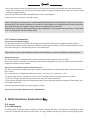
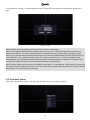
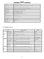
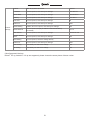
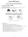
NVR + IP Camera
User Manual
For further help, please visit www.zmodo.com
®
Preface
This product series is a 4 or 8 channel embedded NVR with pentaplex functionality: the product will perform
live video preview, recording, playback, remote access, and backup simultaneously. This advanced product
series receives a high quality video stream that is transmitted digitally by the IP Camera (IPC). This video
signal is encoded by the NVR and enabled for recording, viewing, configuring, and playback. This document
mainly focuses on the installation and configuration of NVR LAN application system. With high performance
video, user-friendly GUI, and practical industrial designs; this series NVR is suitable for civil applications such
as homes, stores, internet cafes, and small businesses in addition to mainstream security and surveillance
applications.
Declaration
• The content in this manual may be different from the product version you are using. If you experience any
issue that is not mentioned in this manual, please contact our tech-support or Zmodo Knowledge Base at
kb.zmodo.com.
• The software will be updated as necessary. Our company reserves the right to update without notice.
Target Reader
This manual is primarily intended for the following users:
• System planner
• Onsite tech-support and maintenance personnel
• Administrator for system installation
• Users for business operation
Conventions
• Click: Refers to left-click with your mouse
• Double click: Refers to left-double-click with your mouse
• Right Click: Refers to right-click with your mouse
• Square brackets "[ ]" indicates the window name, menu name and data sheet, such as [Download]
1
®
Catalog
Part 1: NVR Introduction
1 INTRODUCTION .......................................................................................................................................4
1.1 Brief Introduction .................................................................................................................................4
1.2 Main Functions and Features ..............................................................................................................4
1.3 Installation Instructions ........................................................................................................................4
1.3.1 Device and Accessories list .........................................................................................................4
1.3.2 Front Panel ..................................................................................................................................5
1.3.3 Rear Panel ...................................................................................................................................5
1.3.4 Remote Controller ........................................................................................................................5
1.3.5 Hard Drive Requirements ............................................................................................................6
1.3.6 Hard Drive Installation .................................................................................................................6
1.3.7 Device Connection .......................................................................................................................7
2 NVR INTERFACE INSTRUCTION ............................................................................................................7
2.1 Login ....................................................................................................................................................7
2.2 Shortcut Menu .....................................................................................................................................8
2.3 Main Menu ..........................................................................................................................................13
2.3.1 Playback ......................................................................................................................................13
2.3.2 INFO ...........................................................................................................................................14
2.3.3 Setting ........................................................................................................................................15
2.3.4 IPC MANAGE .............................................................................................................................24
2.3.5 Advanced Setting .......................................................................................................................24
2.3.6 Backup ........................................................................................................................................21
APPENDIX ..................................................................................................................................................29
3.1 SPECIFICATIONS ................................................................................................................................29
3.2 System Default Values ..........................................................................................................................30
Part 2: IP Camera Introduction
1. PRODUCT INTRODUCTION ..................................................................................................................32
1.1 BRIEF INTRODUCTION ....................................................................................................................32
1.2 MAIN FEATURES .............................................................................................................................32
1.3 INSTALLATION STATEMENT ...........................................................................................................33
1.4 NETWORK IP CAMERA CONNECTION ..........................................................................................33
2
®
2. LOG IN ....................................................................................................................................................33
3. PREVIEW ...............................................................................................................................................35
4. SYSTEM SETTING .................................................................................................................................36
4.1 LOCAL CONFIGURATION .................................................................................................................36
4.2 REMOTE CONFIGURATION .............................................................................................................37
4.2.1 Video Setting ..............................................................................................................................37
Video Coding ..............................................................................................................................37
Video Block .................................................................................................................................38
4.2.2 Network Parameter .....................................................................................................................39
Wired Setting ..............................................................................................................................39
Wi-Fi Setting ...............................................................................................................................39
Listener Port (LPRT) ...................................................................................................................41
PPPOE .......................................................................................................................................41
UPnP (Auto Port Mapping) .........................................................................................................42
Email ...........................................................................................................................................43
FTP .............................................................................................................................................43
DDNS .........................................................................................................................................44
4.2.3 Video Setting ..............................................................................................................................45
4.2.3.1 Video Loop .....................................................................................................................45
4.2.3.2 Video Plans ....................................................................................................................45
4.2.4 Alarm setting ...............................................................................................................................46
4.2.5 System Information .....................................................................................................................46
4.2.6 Advanced Setting ........................................................................................................................47
4.2.6.1 User Management ..........................................................................................................47
4.2.6.2 Periodic Maintenance .....................................................................................................48
4.2.6.3 Software Update .............................................................................................................49
5. APPENDIX ...............................................................................................................................................50
APPENDIX 1 SPECIFICATION .................................................................................................................50
APPENDIX 2 SYSTEM DEFAULT PARAMETERS ...................................................................................50
APPENDIX 3 APPLCIATION FOR DDNS DOMAIN SERVICE .................................................................51
3
®
Part 1: NVR Introduction
1 Introduction ▇▅▃
1.1 Brief Introduction
This product series is a 4/8 channel embedded NVR with pentaplex functionality: the product will perform live
video preview, recording, playback, remote access, and backup simultaneously. This advanced product series
receives a high quality video stream that is transmitted digitally by the IP Camera (IPC). This video signal is
encoded by the NVR and enabled for recording, viewing, configuring, and playback. It applies professional
grade, high performance video audio encoding solution, combing with simple, sophisticated UI interface and
practical industry design. Not only for CCTV security which is perfect for home and business. It is simple to
install and operate.
1.2 Main Features
*Supports Mouse & IR Remote Controller;
*Supports Stable Connection with IP camera;
*Supports 4/8-Channel IPC Stream Input and Forwarding;
*Obtain Video Signal from Front-device IP Cameras;
*Supports Multiple Recording Modes;
*Built-in SATA Interface, Supports SATA HDD between 80GB and 2TB of storage;
*Supports USB Backup through USB Flash Disk, and USB Removable Hard Disk;
*Supports Preview & Playback under various Video Resolutions;
*Supports Linkage Channel Audio Alarm, Report to the Alarm Center, and Email Alert;
*Supports TCP/IP Protocol & DDNS;
*Supports Auto Maintain, Software Update and Restore to Factory Defaults.
1.3 Installation Instruction
1.3.1 Device and Accessories List
When you receive the product, please check the equipment and accessories according to the packing list in the
package box.
4
®
1.3.2 Front Panel
Table 0-1 Front Panel Description
Type
Name
POWER
LED
Description
Power indicator: Red, lights when the power is on
Hard disk indicator: Blinks red once per 5 seconds when the hard drive is reading and/or writing;
HDD
the HDD indicator is dark when the HDD is not reading or writing.
1.3.3 Rear Panel
Table 0-2 Rear Panel Description
NO.
Interface
Description
VGA Output
1: DIN-15
Alarm Input
4 Channel Input
Alarm Output
1 Channel Output
Network Interface
1 : RJ45 10/100M
USB Interface
2: USB 2.0
3
RS485
1: Send & Receive Data, half-duplex interface (+ -)
4
power
DC 12V
1
2
1.3.4 Remote Controller
Table 0- 3 Remote Controller Description
NO.
Name
Discription
1
Power
Turn on/off the device
2
Rec
Start/Stop recording
•Input numbers in the editable box
3
NO. (1-9)
•One key channel selection in preview mode
•One key channel selection in playback mode, and enlarge the singlechannel screen
5
®
•Apply for group use to choose channels above 10 in preview mode
4
NO.10+
5
NO.0
•Apply for group use to choose channels above 10 in playback mode,
and enlarge the single-channel screen
Input 0 in the editable box
6
Backspace, delete input in the editable box
7
Direction: Left
8
Direction: Right
9
Direction: Up
10
Direction: Down
1) Press to confirm in menu mode
11
OK
12
2) Shift key to choose recording type in recording schedule
3) Change the attributes of motion detection area while setting the
areas of motion detection
Switch from single screen and multi-screen in preview mode
Auxiliary function key:
1)Switch from single screen and multi-screen in preview and playback
mode
2)Enter and exit paste (copy) status in motion detection area setting
and recording mode setting
3)Set the playback start and end points in the video data search
13
FN
14
MENU
Enter the main menu of setting interface
15
ESC
Return or exit operations
16
PTZ
Enter the PTZ control interface
17
BACKUP
Backup video files
18
TV/VGA
Switch from TV/VGA Output mode
19
CLEAR
Cancel alarm under alarm status
20
SEQ
21
Enable or Disable channel touring according to the touring settings;
Press to pause and restart while touring
1. preview mode: pop out playback interface;
2. playback mode: shift between play and pause
22
Playback mode: Stop play
23
Playback mode: 8x, 16x rewind
24
Playback mode: 1x, 2x, 8x, 16x, 1/8, 1/4, 1/2 fast forward
1.3.5 Hard drive Requirements
The hard disk is not included in factory fittings. You may need to purchase SATA hard drive separately. This
NVR only supports SATA hard drive storage between 80G and 2TB.
1.3.6 Hard Drive Installation
1.Open the NVR top cover, take out the damping washers in the screw bag, and then put the 4 damping
washers into the clamping slots (four protruding steps) in the case;
2.Connect the SATA data cable and HDD power cord to HDD;
6
®
3.Lift up the hard drive with your hand, and turn over the case to make sure that the four holes at the bottom
of the case correspond to the hard drive mounting holes, and then fix the hard drive using four 4 M3*12 Head
Screws plus plain washers.
4.Connect the SATA data cable and HDD power cord to the backplane.
5.Close the cover, and fix the case with screws.
Note1: It is highly recommended to install a DVR-Rate Hard Drive into this NVR in order to ensure that
the Hard Drive can handle continuous use without wearing down and malfunctioning. Please purchase
your Hard Drive from a verified seller to ensure the quality of the hard disk.
Note2: Please format the HDD immediately after installation, or the system will experience a "Hard disk
error" accompanied with an audible alarm.
1.3.7 Device Connection
▲Connect to the Power Supply
You should first make sure that the AC voltage connected with the NVR power adapter matches with the
requirements. And then connect the power adapter to power input interface of NVR, the power indicator on the
front panel will light on, indicating the power is connected right.
Note: Please use the power adapter included in the package to avoid any damage to the equipment.
▲Network Access
The device provides a standard RJ45 interface, which can easily access the LAN or WAN.
During the network connection, you should provide sufficient bandwidth to ensure the fluency and clarity of the
images transmitted over the network.
▲Connect to the Alarm Input and Output Devices
The alarm input device should be the type of GND connected alarm or voltage input alarm, which can be set as
N/O. or N/C.
The requirements of voltage alarm signal input level: low level: 0~2V; high level: 5~15V.
The green angle pins are supplied for access of PTZ and alarm devices. Wiring steps are as below:
1. Pull out the angle pins that inserted in the alarm input and output interfaces;
2. Unscrew the screws using micro Philips screwdriver, insert the signal cable into interface under spring, and
then tighten the screws.
3.Plug in the connected pins into green angle pin socket.
▲Connect to the Video Output Device: VGA Monitor
2. NVR Interface Instruction ▇▅▃
2.1 Login
2.1.1 Starting Up
The Power LED on the front panel will light in red after complete the wiring. Press [Power on/off] button to start
up device. System will first enter preview screen. The login window will pop up by either pressing [ESC] button
7
®
on front panel or remoter, or right clicking the mouse. Select user and input the corresponding password to
login.
Figure 1 Log in
Note1: Please allow the NVR up to 60 seconds to boot up completely.
Note2: The default password for the Admin username is 111111. The default password for the User
username is Admin. The admin password can be restored to factory default by connecting a metal
paper clip or small metal object to the terminals on the internal motherboard JP1 port. The admin user
can modify the user’s password after login. The system supports up to 16 users, the Admin is the
administrator user with all permissions, whose name cannot be deleted or changed. The Admin user
can add and delete all other users and the permissions corresponding.
Note3: Please follow the procedures to install the hard drive. “No Hard Drive” will prompt if you start up
the device without hard drive, please check the connection between NVR and hard drive if you installed
but still pop out "No hard drive" warnings.
2.2 Shortcut Menu
After login, right click the mouse, you will enter the shortcut menu, as figure 2 shows:
8
®
Now the monitor will show 4 channel video and one vertical menu. Here are functions of the buttons of the
shortcut menu:
[View 1CH]: Single click the button
, The right side displays 4 channels( as figure 3), Choose
one channel to view the full image. Click once again to go back to the 4 channel image.
Figure 3
[View 4CH]: Single Click
Display all four channel video footage.
[Color Setting]: Click
(Figure 4) to choose a channel to alter the color, then adjust the
parameters of brightness, contrast and gray level. You can adjust by dragging the progress bar or clicking "+", "-".
Figure 4 Color Setting
[Play Back]: Click
to enter the playback interface as figure 5 shows:
9
®
Figure 5 Playback
Enter the Playback interface, choose channel(CH1, CH2, CH3 or CH4), select correct video time period. You
can search all of the videos in the current month. The date highlighted in yellow indicates that video exists on
this day. Single click the date at which record files exist in order to see the file list. The list below can display all
the video files at this day, as figure 6 shows:
Figure 6 Date Select at Playback Interface
You can choose to display video files per video types (click corresponding video types, the file of this kind will
be displayed, or it will not be displayed). Single click files listed in certain time period, click
pause, click
for fast rewind, click
for fast forward, click
to play and
to stop playing, click
slowplay.
Select the time shift icon at the bottom right corner,
video files displayed: 24hour, 2hour, 1hour, 30minutes
, you can set the time period of the
[Record]: Click
button to set manual, schedule and alarm recording for single channel or all
channels, as figure 7 shows:
10
to
®
Figure 7 Record Setting
Choose the record types: Select all to select all the four channels, uncheck all to stop recording of four
channels. You can choose single number to lunch recording of this channel.
[Add IPC]: Click
to enter IPC management interface as figure 8 shows:
Figure 8 IP Camera Config
Note: Please read completely through Part 2: IP Camera Introduction of this manual before adjusting
any settings on the IP Camera Config Menu. IP Cameras must be connected to the same internet
network as the NVR before any changes can be made to the IP Camera Config menu. Please read the
2.3.3.4 (network setting) and config the network setting before config the IP camera.
You can add IP cameras by manually or automatically.
[1] In order to add an IP camera manually, click on the option that reads .Add Device Manually. Input the IP
address of IP cameras and corresponding listening port, then click OK. If the IP address was input correctly, a
video image of the camera should appear on the screen.
[2] Select blank channel, and click the [search] button to enter IP search interface, now it will list all the IPs of
IP cameras searched by NVR. Click the IP you wish to add to the NVR, then click [Add], if the IP address was
input correctly, a video image of the camera should appear on the screen.
[3] Click [One Step to Add], you can add IP cameras in LAN in one step.
[4] In order to enable to auto-add IP Camera function, click [Search and Add All Devices Automatically] on the
top left corner, then the system will automatically search IP cameras which are at the same segment in LAN. If
the IP address was input correctly, a video image of the camera should appear on the screen.
[5] In order to delete an IP address out of the IP Camera Config menu, Click the IP , and then click [Dele
11
®
Device], now you can delete IP cameras from the NVR.
Note: The IP of IP cameras and NVR should be in the same network segment and in the same LAN, or
else you will not add IP successfully.
[HDD Status]: Click
, into hard drive information interface as figure 9 shows:
Figure 9 Hard Drive Information
HDD INFO shows the status of the hard drive which is connecting to NVR, including total space and free
space, Click [Refresh] to check the remaining storage on the hard drive.
In order to format the Hard Drive, select a hard drive number, then click [Format].
Note:
1. You need to input the password of current user when formatting hard drive, and the system will
reboot after the format is complete.
2. Formatting the Hard Drive will erase all data saved in the hard drive, please back up the important
data before formatting.
[Main Menu]: Click
to enter the main menu interface, Main menu includes playback,
information, Setting, IPC manage, advanced setting and backup. Please refer to menu description .
Figure 10: Main Menu
12
®
[Log Out]: Click
, to log out of the NVR interface. To enter the interface once again you only need
to right click the mouse, then login in again with correct user name and password.
[Shut Down]: Click
, and a dialog box will prompt you for the password. After inputting the
password, the system will power down.
2.3 Main Menu
Figure 11 Main Menu Display
As figure 11 shows, the system main menu can be divided into six parts: video playback, system information,
system setting, IP camera manage, advance setting and video record backup.
2.3.1 Playback
Click
to enter the Playback interface, as per figure 12 shows. Please refer to section
[2.2] of this manual to view the introduction of [Playback].
Figure 12 Playback
13
®
2.3.2 Information
Click
to enter the system information display, as figure 13 shows:
Figure 13 Information
[HDD Info] Click
to enter the Hard Drive information menu, as shown in figure 14. Please refer to
section .2.2. of this manual to view the HDD Status steps.
Figure 14 Hard Drive Information
[System Logs]: Click
to enter the Log interface as figure 15 shows:
14
®
Figure 15 System Log
User can select alarm log and system log, also choose the time and date, click [Search] it will display the
required logs.
[System Version]: Click
to check the system version infromation as figure16 shows:
Figure 16
It will display the current software version, hardware version, device name and MAC address Etc.
2.3.3 Setting
Click
to enter the interface of parameter seeting, as per figure 17 shows:
15
®
Figure 17 Setting
2.3.3.1 General
Click
to enter the General Settings interface, as per figure 18 shows:
Figure 18 General Information
User can set parameters such as system time, system language, time format and video pack duration. Etc.
[System Time] You can modify the current system time, click Save to take effect immediately.
[Time, Date Format] You can set the date as year-month-day or day-month-year, also set time format as 24
hours and 12 hours. You can set time and date as your need.
[Language] You can set language as Chinese or English, save and reboot the system. The setting will take
effect immediately.
[HDD Full] When hard drive is full, if you set as [Overwrite], then hard drive will automatically clear the oldest
video files and continue recording. If you set as [Stop Record], the video will stopped recording when hard drive
is full.
[Pack Duration] You can set video record pack time to either 60 minutes, 45 minutes, 30 minutes, or 15
minutes.
16
®
[Record Delay] You can set up to 99s for the record delay time. After you’ve set the record delay time, the
record packing will be restarted after the delay time passed.
[Pre-record] Set up to 29s of the pre-recording time, After you’ve set the pre-recording time, it will start
recording before it triggered alarm, the in advance time is the pre-record time.
[Startup wizard] You can click the check to lunch startup wizard, Then you can set a group of basic setting
when system reboots.
[Sync IPC time] After you modified system time of NVR, the time of IP camera will be in synchronization.
After successfully adding IP cameras, the time on IPC will be synced with NVR’s time.
After you finished the setting, please click [Save] to let the configuration take effect immediately.
2.3.3.2 Video Streams
Click
to enter video code setting interface as figure 19 shows:
figure 19
[Video quality] The user can choose the appropriate desired image quality: Best, Very Good, Good, Common,
Low.
[Resolution] Set the image resolution. Main Stream 720P(1280×720=921600 pixel) or VGA(640×480=307200
pixel), Sub stream QVGA(320×240=76800 pixels).
[Frame rate] Set the coding frame rate per second. For weaker network connections, it is recommended to
reduce the frame rate to control the coding bit rate to ensure the smoothness and continuity of the moving
footage.
[Bit Rate Type] Two types: CBR(Constant bit rate)and VBR(Variable bit rate) to choose, CBR enables constant
bit rate coding, VBR enables variable bit rate coding.
After setting parameters, click the [Save] button, the setting will take effect immediately.
2.3.3.3 Schedule
Click
to video schedule setting as per figure 20 shown:
17
®
Figure 20
Following Features can be set::
[1] [Channel] You can choose all to set four channels or set single one channel by selecting from CH01, CH02,
CH03, and CH04.
[2] [Type] Three types of recording types to choose: Schedule recording, alarm triggered recording and motion
triggered recording.
[3] [Week/Time] You can choose one day from Monday to Sunday, or choose everyday in the week. You must
also check the time period for you to choose. You need to click the time check to enable the time selection.
After setting parameters, click the [Save] button, the setting will take effect immediately.
2.3.3.4 Network Setting
Click
to enter the Network Parameter configuration menu, as Figure 21 shows:
Figure 21
[DHCP] If the router allows DHCP functionality, select DHCP. The IP Camera will obtain IP address
automatically from the router. If the router does not allow for DHCP functionality, then the IP address must be
obtained manually.
[IP address] Set the wired cable IP address of the NVR. The factory setting IP is 192.168.0.10, network
segment is 192.168.0.1.
18
®
[Subnet mask] Default: 255.255.255.0 (It is highly recommended not to change this section.)
[Gateway] Set gateway IP of the NVR, for example if the NVR accesses the public network through the router,
the gateway IP need to be set as the router IP which has accessed the public network.
[DNS address] If the user has a DDNS account, the DNS address needs to be set as DNS address of the
place where the device is belonging to.
Note: DNS parameters, MAC address and parameters of three ports have been configured in factory,
please do not change it randomly.
After setting parameters, click the [Submit] button, the setting will take effect immediately.
[PPPOE]: Click
into PPPOE Setting, as per figure 22 shows:
Figure 22
[ON] Set to enable or disable the PPPOE dial-up function.
[Account] The ADSL dial-up account, obtain from internet service provider.
[Password] Password of ADSL dial-up account, obtain from internet service provider.
After setting all parameters, click the [Save] button, the setting will take effect immediately.
[DDNS] Click
into DDNS Setting as figure 23 shows:
Figure 23 DDNS Setting
Dynamic DNS setting allows the user to bond the device with a fixed domain name if the user has a dynamic IP
address. The user may register for a free DNS service at http://zmododns.com/
[ON] Check to enable or disable the DDNS function.
[Server] http://zmododns.com/ is highly recommended, as this DNS service is operated and maintained by
Zmodo.
[Domain] The device domain which is set by user, such as mydvr.zmododns.com.
19
®
[Account] The user name which you registered on DDNS server.
[Password] The password which you registered on DDNS server.
After setting all parameters, click the [Save] button, the setting will take effect immediately.
[E-mail] Click
enter Email setting interface, see figure 24 shows:
Figure 24 Email Setting
This menu is for enabling email notification upon motion detection or alarm.
[SSL ON] Enable or disable SSL, based on the type of email server
[SMTP port] Port of SMTP Server.
[SMTP server] Email server address, such as smtp.gmail.com.
[Send to] Email address to receive the email.
[From] Email address to send email.
[Password] Log in password for the email box.
After setting all parameters, click the [Save] button, the setting will take effect immediately.
[UPNP] Click
to enter UPNP setting interface, as figure 25 shows:
Figure 25
[ON] If in LAN it has server with UPNP functionality, enable this function, the server will automatically forward
the set port to public network.
[Web mapping port] Set the web port which will be mapping to the server.
[Video mapping port] Set the digital video port which will be mapping to the server.
[Mobile phone mapping port] Set the mobile phone port which will be mapping to the server..
After setting all parameters, click the [Save] button, the setting will take effect immediately.
Note: Port mapping can be selectable between 1024~65535. It can't be repeated.
20
®
[FTP] Click
enter FTP setting interface, see figure 26 shows:
Figure 26 FTP Setting
FTP services will send the alarm triggered recording file or captured photo via FTP to certain FTP server.
[Server] IP address or HTTP network address of FTP server.
[Account] User name of the FTP Server.
[Password] Password of the FTP Server.
After setting all parameters, click the [Save] button, the setting will take effect immediately.
2.3.3.5 [Display]
Click
to enter display setting interface as figure 27 shows:
Figure 27
[Channel and time display] When this option is checked, it will display the name and time of channel during
live video, when this option is not checked, it will not display the name and time of channel during live video.
[Channel name] Modify in the pane behind [Channel Name]. The channel name will be shown on the top left
of the video image. It supports maximum 16 characters. Click the [Save] button, the setting will take effect
immediately.
[Resolution] You can configure the display resolution of the monitor.
[Transparency] The transparency of interface can be configured in seven levels from 1 to 7.
21
®
[Enable AUTO SEQ] Choosing channel numbers from 1 to 4 and setting the tour intervals, the system will
display four channels’ video image in full screen in certain sequence, the detailed steps as following:
[1] Set the interval time. It’s the time interval between two channels’ full screen display
[2] Set channels of video tour sequencing. You can set the channel numbers as per your need.
[3] Click whether to go back to quad screen. When the check box is enabled, the system will go back to quad
screen first and then continue sequencing after one tour of sequencing.
Click [Save], the setting will take effect immediately.
2.3.3.6 External Alarm
Click
to enter alarm setting, as shown in figure 28:
Figure 28 External Alarm
Alarm setting steps are as follows:
[1] [Alarm In] Choose the channel number of alarm input from all four channels, users can choose according
to their specific needs, check ON to turn on alarm input channel.
[2] [Type] Choose the type of alarm from two options: Normally Open & Normally Close.
[3] Check [Alarm Out] to set the alarm output, the device only support one channel alarm output, user can
also set the time of alarm delay ( up to 30secs)
[4] [Trigger Period] iis for setting the alarm triggered period. Click [set] to set the alarm triggered period, user
can set the period of alarm triggered according to their specific needs.
[5] [Record Channel] is for setting the channel of alarm triggered recording, the user can choose any channel
or all 4 channels for alarm triggered recording.
[6] Choose the type of alarm, the device supports E-mail Alarm & Buzzer Alarm. Choose E-mail Alarm, then
emails will be sent to appointed email account when alarm is triggered. Choose Buzzer, then there will be
buzzer sound when alarm is triggered.
Click [Save] to save all the above settings.
2.3.3.7 Motion Detection Alarm
22
®
Click
to enter motion alarm interface, as shown in figure 29:
Figure 29 Motion Alarm
Steps of setting up the motion detection are as follows:
[1] Set the alarm channel, user can choose either one channel or all channels to set alarm;
[2] Check [Record] to turn on motion detected recording;
[3] [Alarm delay] is for user to set the alarm sound duration (Ranges from 2 – 30secs)
[4] Check [Alarm Out] for alarm output
[5] Check [Buzzer] to turn on buzzing sound when motion detected, Click [Save] to save the settings.
2.3.3.8 Hard Drive Alarm
Click
to enter hard drive alarm setting interface, as shown in figure 30:
Figure 30
There are three types of HDD alarm: No Disk, HDD Error, and HDD Full. Check [ON], then warning box will
23
®
popup if any of above abnormal situations appears next time when you turn on the device. Check [Buzzer],
then system will alarm buzzer if any of above abnormal situations appear next time when you turn on the
device.
Note: You need to click [Save] to take affect the settings.
2.3.4 IPC Management
Click
to enter IPC configuration interface, as shown in figure 31:
Figure 31
Please refer to [Add IPC] at section [3.1] of this manual for the details for adding IP Cameras to the NVR.
2.3.5 Advanced Setting
Click
for advanced setting interface, sub-menu interface as shown in figure 32:
Figure 32 Advance Setting
24
®
2.3.5.1 Account
Click
to enter user management interface, menu interface as shown in figure 33:
Figure 33 System Account
Users can modify the user name, password, and permissions in the user management interface, they can also
add and delete users.
[Change User Password] Left click the user you need to change, and then click [Edit Account], interface as
shown in figure 34 will popup.
Figure 34 Edit Account
Type in the old password, set a new password, and then re-enter the new password, click [Save] to save your
new password. Password changed successfully.
[Add User] Click [Add Account] to enter add user interface, as shown in figure 35:
25
®
Figure 35 Add User
You can add both administrator and ordinary user here. Check [Administrator] at the top left to add
administrator, while uncheck it to add ordinary users. Users can set the username and password according to
their specific needs. After setting, click [Save] to save the settings. User added successfully!
[Delete User] Click [Delete Account] to delete users. Click the user you want to delete, then click [Delete
user] to popup a prompt box to type in the user password, as shown in figure 36, User only need to input the
administrator user password to delete the user you want to.
Figure 36 Delete User
Note: Only the administrator user can delete other user information, ordinary users do not have the
permission.
2.3.5.2 Restore Factory Setting
Click
to Restore the factory settings, as shown in figure 37.
26
®
Figure 37
System will popup a message interface after clicking default, hit [OK], user will need to input the user password
to restart the system to finish restore the factory settings.
Note:
1. Only administrators have the permission to restore the factory settings, ordinary users do not have
the permission.
2.Parameters will also restore to factory settings after you click restore the factory settings, users can
edit them according to specific needs.
2.3.5.3 Upgrade System
Click
to enter system upgrade interface, as shown in figure 38:
Figure 38 Upgrade System
Note: Please have all IP Cameras disconnected from the NVR while attempting a software update.
Users can upgrade the system either under NVR IE interface, or using a USB flash drive. (Before upgrading
the system, users need to copy the upgrade files in the current directory of USB flash drive, and then insert the
USB flash drive to the NVR USB port.) After well insert the USB flash drive, click [Upgrade], system starts to
upgrade.
27
®
Note:
1. Do not cut off the power during system upgrading.
2. If you insert the USB flash drive before turning on the device, system will automatically begin
updrading after device boot. Users do not need to enter system upgrade interface, but make sure that
do not cut off the power.
3. Users can reboot the NVR after an unsuccessful software update to attempt the software update
again.
2.3.5.4 System Maintenance
Click
to enter system maintenance interface, as shown in figure 39:
Figure 39 System Maintenance
Under system maintenance, users can setup any time point at any date for automatic system maintenance.
Users only need to input a time point, then choose a date from Monday to Friday, and click [Save], system will
automatically restart for maintenance.
2.3.6 Back Up
Click
to enter the video backup interface, as shown in figure 40.
Note: You must insert a USB flash drive or removable HDD before backup.
28
®
Figure 40 Backup
Video Backup Steps are as follows:
[1] Insert USB flash drive or other removable HDD;
[2] Choose the channel and timeline you want to backup, click [search] to list the corresponding video files. [Prev.
Page] means turn to previous page, [Next Page] means move to the next page, [First Page] means go to the
first page, while [Last Page] means move to the end page.
[3] Click the video file you want to backup, the status become yes, then click [Backup] to start backup the file.
Note: There is status notification during backup, please do not pull out the USB flash drive under
unfinished status.
Appendix:
3.1 Product information and default parameter:
Model
ZMD-NV-SBN4/ZMD-NV-SBN8/ZMD-NH-SBN4
Video System
NTSC
Operation System
Linux Based
Video Output
VGA/720P
Display Frame Rate
120fps @VGA
Display Resolution
1024×768@60Hz, 1280×1024@60Hz
Recording Frame Rate
120fps @VGA
Record Resolution
120fps @VGA
Record Mode
Manual / Time Scheduled / Alarm Triggered/Motion
Playback Mode
Normal Play /Fast Forward /Fast Rewind/Slow Play
Network Function
Real-time Preview, Record, Playback, Download, NVR Setting, Upgrade, Mobile &
Email Function etc
Network Interface
RJ45, 10M/100M
29
®
Net Protocol
TCP/IP, PPPoE, DHCP,DDNS
3G Mobile
Support mobile phone based on iPhone® 4.3 up, Android™ 2.2 up
Mobile Function
4 Channel Viewer / Channel Switch / Control PTZ
Alarm Mode
Trigger Record, Email Alert, Audio Output, Alarm output. etc
Sensor/Alarm
4 CH Sensor Inputs / 1 CH Alarm Output
HDD Interface
1 SATA HD, Support up to 2TB
USB Interface
USB 2.0, USB Backup, Mouse
Backup
USB Flash Disk, Removable HDD, SATA HD
Remote Control
IR Remote Control
Remote Access
LAN or Internet Browsing
Power Supply
DC12V, 3A
Dimension
8.66"*8.07"*1.57"
Gross Weight
5.65lbs
3.2 Default Values
Items
System
Setting
Record
Settings
Options in Menu
Default
LANGUAGE
Simplified Chinese, English, Czech
English
Video Standard
NTSC
NTSC
VGA Setting
1024×768@60Hz, 1280×1024@60Hz
1280×1024@60 Hz
Time Format
12 hours, 24 hours
24 hours
Time Setting
No menu options, click directly into sub-menu settings
Password Setting
No menu options, click directly into sub-menu settings
HDD Overwrite
ON/OFF
Add User
No menu options, click directly into sub-menu settings
Delete User
No menu options, click directly into sub-menu settings
Authority
Management
No menu options for current user, click directly into sub-menu
settings
Current User: admin
Schedule
No menu options, click directly into sub-menu settings
24 hours recording
Color Setting
brightness, contrast, Chromaticity & saturation: 128\46\128\64
3/35/127
Motion Detection
Picture Enlarge, Alarm Output, Buzzer, Upload Center, Email
OFF
Channel Title
No menu options, click directly into sub-menu settings
CH1/2/3/4
Year-month-day
hour : minute PM
Password: 111111
User: admin
ON
30
®
Network
Settings
Network
Static IP, Dynamic IP, PPPoE
Static IP
IP Address
No menu options, click directly into settings
192.168.0.10
Subnet Mask
No menu options, click directly into settings
255.255.255.0
Gateway
No menu options, click directly into settings
192.168.0.1
HTTP Port
No menu options, click directly into settings
80
Media Port
No menu options, click directly into settings
8000
PPPoE Setting
ON/OFF; No menu options, click directly into settings
OFF
PPPoE Address
No menu options, display IP address when PPPoE dial-up
successfully
0.0.0.0
DNS address
No menu options, click directly into settings
202.96.134.133
Dynamic Domain
Name
No menu options, click directly into settings
OFF
Email Setting
No menu options, check the settings directly
Mobile Port
No menu options, click directly into settings
9000
UPnP setting
Click directly into sub-menu settings
OFF
FTP setting
Click directly into sub-menu settings
OFF
Client Supported Versions:
iPhone® 4.3 up, Android™ 2.2 up are supported; please choose the smart phone of these version.
31
®
Part 2 IP Camera Introduction
1. Product Introduction ▇▅▃
1.1 Brief Introduction
This product is digitally monitored with a traditional analog camera and web video service. Efficient Linux
system, code in flash and small size that’s reliable and steady.
Power
Power
Network
Reset
Reset
Network
Figure 1-1 Network IP Camera and Its Cable Ports
1.2 Main Features
* The highest pixels for100 W, 4M frame rate, real-time image
* Supports up to Max three video streams: One 720P, One VGA, One QVGA;
* Advanced video compression standard, high compression rate and flexible operation
* 720P IP camera applies 1/3”CMOS sensor, VGA IP camera applies 1/4” CMOS sensor, fluid motion pics
* Automatic snapshot in all circumstance
* One key rescue system, network parameter modification and mobile phone live monitor
* Build-in WEB browser supports IE access
* Support multiple user simultaneously, multi-level management ensures high system security.
* Support motion detection alarm (area, sensitivity configurable) and e-mail alert function
* Support online system upgrade by remote control
* Automatic recovery function when the system temporarily loses internet connection.
* Support PPPOE, DDNS, LAN, and Internet (ADSL, Cable Modem)
32
®
1.3 Installation Statement
During installation and operation, please pay attention to the following items:
1.When you received the package product, please check the equipment and accessories according to the
packing list inside the packing case.
2.Before installation please carefully read this user manual.
3.When you install the IP camera, please close the power source of all the related devices.
4.Check the voltage of the power source, to prevent device damage by mismatching of voltage.
5.Installation environment: please do not use equipment under high humidity or temperature. Make sure there
is good ventilation. Do not install it in an environment that experiences frequent vibration.
1.4 Network IP Camera Connection
Figure 1-4 Device Connection of Network IP Camera
Step one: Connect the IP Camera to internet through network cable.
Step two: Connect the power adaptor in the package to the power plug of the IP camera, and access into
electric supply.
Step three: Open the PC, connect with the front-end network IP camera, to configure via software.
Note: It can also apply the way of IP Camera directly connecting with PC.
Note: When using IE browser to visit IP Camera, the IP of local PC should be in the same network
segment with the IP of the IPC.
2. Log in
▇▅▃
When using IE (Internet Explorer) to visit IP camera for the first time, you have to set the security level for
ActiveX controls.
Set security level: Open Internet Explorer, enter the IE Tools menu [Tools/Internet Options/Security Settings/
Custom Level…], set Active X Controls and Plugins to “enable” or “Prompt”, and set the IP address of the IP
Camera as “Trusted sites”.
33
®
Figure 2-1 Security Level Setting
Install ActiveX and plugins: Type the network camera IP address in the IE browser address bar, and press [Enter]
to pop out dialog box of install ActiveX. Click [OK] to install.
Log in and Preview: In Login screen, type in network camera username, password, choosing language and
click [OK] to enter the video preview interface.
Default:
IP Address: 192.168.0.100
User Name: admin
Password: 111111
Figure 2-2 Safety Dialog box
34
®
Figure 2-3 Login Interface
3. Preview ▇▅▃
Figure 3-1 Real-time Preview Interface
In the real-time preview interface, the user can control the video channel switch, record, snapshot, full screen
preview, image process, image color, and direction configuration.
[Video channel] Double Click the channel number to open the video channel to view image, right click and
choose "Close" to close the video channel.
[Video stream] Right Click the channel number to choose stream type(720P, VGA or QVGA)
[Record] Right click the image, choose "record" check to start or Close local recording
[Capture] Right click the image, choose "capture" to capture photos.
[Full screen preview] Double click the image to full screen preview, double click once again to go back to the
original image size.
35
®
[Image process] The object of image processing includes brightness
use mouse to drag the slider to set these items, as figure 3-2.
, contrast
, saturation
,
[Color and direction configuration] Image color can be black and white or color, the image can be mirrored
or reversed as figure 3-3.
[PTZ Control] PTZ operations such as up, down, left and right, and lens operations such as varies Zoom, focal
length, and Iris, as figure 3-4.
Figure 3-2 Image Parameter
Adjustment
Figure 3-3 Color and Direction
Control Figure
[System parameter setting] Click this button
[Reboot device] Click this button
3-4 PTZ Control
to enter into system parameter setting interface.
to reboot the device.
4. System Setting ▇▅▃
4.1 Local Configuration
Figure 4-1 Local Configuration
36
®
[Video files packing time] Set the video file packing time,
[Video/captured file storage directory] Set file path for local recording and capture.
After configuration is finished, click [Submit] button, the configuration will take effect immediately.
4.2 Remote configuration
4.2.1 Video Setting
Character Overlay
[Title] Name of video channel will be shown on the up left of the image, maximum 16 characters. Click the
check box and it will display OSD. Un-check the check box, and it will not display the title.
[Time format] You can choose whether to display title , date and time, and also you can choose the time
format.
After setting the date and time, click the [Submit] button, the setting will take effect immediately.
Figure 4-2 Character Overlay Setting
*Video Coding
[Video quality] The user can choose the appropriate desired image quality: Best, Very Good, Good, Common,
Low.
[The type of stream] Two types: CBR(Constant bit rate)and VBR(Variable bit rate) to choose, CBR enables
constant bit rate coding, VBR enables variable bit rate coding.
[Resolution] Set the image resolution. 720P(1280×720=921600 pixel), VGA(640×480=307200 pixel) , and
QVGA(320×240=76800 pixels).
[Frame rate] set coding frame rate per second. Under not satisfying network situation, you can reduce the
frame rate to control the coding bit rate, to ensure the smoothness and continuity of the moving footage.
After setting parameters, click the [Submit] button, the setting will take effect immediately.
37
®
Figure 4-3 Video Code Setting
*Video Block
[Video shield switch] Enable or disable the video shield functionality
[Shield area setting] User can set shield area by dragging mouse with left key pressed, and cancel the shield
box on the shield area by right clicking the mouse. You can choose to shield the whole image, or only shield the
part of the image. It can mask up to four areas. You can right click the shield box to cancel this areas’ shield.
After setting parameters, click the [Submit] button, the setting will take effect immediately.
Figure 4-4 Video Shield Setting
38
®
4.2.2
Network Parameter
*Wired Setting
[DHCP] If the router allows DHCP functionality, select DHCP. The IP Camera will obtain IP address
automatically from the router. If the router does not allow for DHCP functionality, then the IP address must be
obtained manually.
[IP address] Set wired cable IP address of IP camera device.
[Subnet mask] Default: 255.255.255.0 (It is highly recommended not to change this setting)
[Gateway] Set gateway IP of IPC, for example if IPC access public network through router, the gateway IP
need to be set as the router IP which has accessed the public network.
[MACaddress] MAC address of IP camera (Read only, cannot change)
[DNS address] If the user has a DDNS account, the DNS address needs to be set as DNS address of the
place where the device is belonging to.
After setting parameters, click the [Submit] button, the setting will take effect immediately.
Figure 4-5 Wired Network Setting
Note: When the network parameter has been revised and saved, the device will reboot. If it is applied in
LAN, please make sure IP address does not conflict with the IP address of other devices or computer in
the same LAN.
*WIFI Setting
[WIFI] Select this check to open the wifi network function of IPC.
[DHCP] If the router allows DHCP function, select this type, IP camera will obtain IP address automatically from
router.
[IP address] Set wireless IP address of IP camera.
[Gateway] Set IP address of the current wireless gateway( router/AP), such as 192.168.0.1.
[Wireless Network Connection] After enabling the Wireless setting, the software will automatically search for
available Wireless networks. The name of all wireless signals including signal intensity and the encryption will
be listed on the screen.
39
®
Figure 4-6 IPC WIFI Network Setting
Click on “add” or double click on an existing network, open ”WIFI Wireless Network Settings” dialog box as the
below figure shows:
Figure 4-7 Wifi Hotspot Setting
If the user entered this screen by double clicking, a network will be assigned automatically. If the user entered
this screen by clicking “Add”, the user has to type in network name, choose a corresponding encryption mode,
and type in the password.
Click .Connect., then close the dialog box, and the connection status will update on the search results list.
“Connected” will appear after network name if the connection was successfully established; if not, please click
"Refresh" to refresh the connection status or re-enter the Wireless Network Settings menu to re-attempt to
40
®
connect to a wireless network.
After saving all parameters, click the [Submit] button, the setting will take effect immediately.
Now pull out network cable, you can access the IP network camera via Wifi.
Note: WIFI setting only works to those types with WIFI function.
Wired network and wi-fi network should not be set in the same network segment.
WIFI mode supported by IP Camera: 802.11b/g protocol(small power WiFi type)
802.11a/b/g/n protocol (large power WiFi type)
*Listener Port (LPRT)
[Web Listening Port] The default port 80(port 80 is recommended)
[Video Listening Port] default 8000 (8000 is recommended).
[Mobile phone Listening Port] default 9000 (9000 is recommended).
After setting all parameters, click the [Submit] button, the setting will take effect immediately.
Figure 4-8 LPRT setting
Note: LPRT can be selectable during range of 1024~65535, can't be repeated. Web LPRT can be 80.
*PPPOE
[PPPOE] Set to enable or disable the PPPOE dial-up function.
[User name] The ADSL dial-up account, obtain from internet service provider.
[Password] Password of ADSL dial-up account, obtain from internet service provider.
After setting all parameters, click the [Submit] button, the setting will take effect immediately.
41
®
Figure 4-9 PPPOE Parameters Setting
*UPnP (Auto Port Mapping)
[UPnP] If in LAN it has server with UPNP functionality, enable this function, the server will automatically
forward the set port to public network.
[Web mapping port] Set the web port which will be mapping to the server.
[Video mapping port] Set the digital video port which will be mapping to the server
[Mobile phone mapping port] Set the mobile phone port which will be mapping to the server.
After setting all parameters, click the [Submit] button, the setting will take effect immediately.
Figure 4-10 UPnP Port Mapping Setting
42
®
Note: Port mapping can be selectable between 1024~65535. It can't be repeated.
*Email
Figure 4-11 Email parameters setting
This menu is used to set Email address and related parameter of alarm email.
[SMTP server] send email server address, such as SMTP server of Google email box: smtp.gmail.com.
[Receive Email address] Email address to receive the email.
[Send Email address] Email address to send email.
[SMTP password] Log in password for the email box.
[Email title] The title of sending email.
[SMTP port] Port of SMTP Server, such as Gmail email server port as 465, SSL enabled.
After setting all parameters, click the [submit] button, the setting will take effect immediately.
Common email server configurations:
Hotmail server
SMTP Server:smtp.live.com
SMTP User:[email protected]
SMTP Port:25
SSL: Enabled
Yahoo Email server:
SMTP Server: smtp.mail.yahoo.com
SMTP User name:[email protected] [email protected]
SMTP Port: 465
SSL: Enabled
*FTP
FTP services will send the alarm triggered recording file or captured photo via FTP to certain FTP server.
43
®
[FTP server] IP address or HTTP network address of FTP server.
[FTP port] Port of FTP server, default port is 21.
[User] User name of the FTP Server.
[Password] Password of the FTP Server.
After setting all parameters, click the [Submit] button, the setting will take effect immediately.
Figure 4-12 FTP parameters setting
*DDNS
Figure 4-13 DDNS parameter setting
Note: It is only necessary to setup DDNS settings on your NVR, please refer to Part 1; section 2.3.3.4 of
this manual for NVR DDNS setup and configuration.
44
®
4.2.3 Video Setting
4.2.3.1 Video Loop
Figure 4-14 Video Loop Setting
[Loop Video] Click loop video, when the storage of SD card is full, system will overwrite automatically to
continue recording.
4.2.3.2 Video Plans
Figure 4-15 Record Type and Record Time Setting
[Type] Three types of recording types to choose: Schedule recording, Alarm triggered recording and motion
triggered recording.
45
®
[Week/Time] You can choose one day from Monday to Sunday, or choose everyday in the week, also there is
a time period for you to choose. You need to click the time check to enable the time selection.
After setting all parameters, click the [Submit] button, the setting will take effect immediately.
4.2.4 Alarm Setting
Figure 4-16 Motion Detection Setting
[Time] Set the protection time of motion detection. It can set detail time period of everyday, up to four time
periods.
[Motion detection] Set open or close of motion detection, enable this switch to edit the motion detection area.
[Motion detection area setting] After enable motion detection switch, the setting interface will appear grid
line. User only needs to click the little cube on the image to set the motion detection area. Right click the little
cube to cancel related area detection.
[Alarm Method] Set linkage output format after triggered alarm. Four methods for you to choose: Capture,
record, email and upload. Sending email is sending motion detection alarm information via email to user, the
detailed Email parameter see chapter 4.2.2. There will be no Email alert if user didn't set email parameter
previously.
[Sensitivity] The sensitivity of motion detection includes three levels: High, Little high, Medium, and Low.
[Output delay] Set delay time of alarm linkage, time range is limited between 0~30sec.
After setting all parameters, click the [Submit] button, the setting will take effect immediately.
4.2.5 System Information
[Version] Display device name, system version, video/audio channel number, sensor/alarm input/output, local
storage.
[Time setting switch] Enable this switch to manually set the system date and time; disable this switch then
the system date and time will be synchronized with local PC only to check the status and can't be configured to
disable this switch.
After setting all parameters, click the [Sync time] button, the setting will take effect immediately.
46
®
Figure 4-17 Version Information
Figure 4-18 System Time Setting
4.2.6 Advanced Setting
4.2.6.1 User Management
Each IP camera can be set up to have up to 15 users. Admin is the system default super user and cannot be
deleted, but the admin password can be changed. User's authority is as following.
Super-User authority: operate and set all the function and parameter of IP camera
Common user authority: The common user is allowed to view video, adjust their password and delete their own
account. Common users are not granted any additional authorities.
47
®
Figure 4-19 User Management Interface
Note: The default user after leaving factory is admin, the password is blank. Both user names and
passwords are case sensitive.
4.2.6.2 Periodic Maintenance
Figure 4-20 Periodic Maintenance Setting
[Periodic maintaining] Choose to open periodic maintenance and set maintenance time, detailed
maintenance time on everyday can be configured.
After setting all parameters, click the [Submit]
[Restore factory setting] Click this button to recover all the setting of the device back to factory setting.
48
®
[Reboot device] Click this button to reboot the device.
Note: Periodic maintenance and reboot the device will need to wait for 30 seconds to restore video
surveillance.
4.2.6.3 Software Update
Figure 4-21 Software Update
[Update] Click "..." to browse for the correct update file (application file: IPC-APP, Please not change the file
name), click "Update". During the update, it will display update information. After update finished, IP Camera
will reboot automatically. Log into the device once again and enter the software update interface to check
whether the system version has been updated.
Note: During updating, please do not disconnect the camera from its power source or from the internet
connection.
49
®
5. Appendix ▇▅▃
Appendix 1 Specification
Type of Parameter
Camera
720P Network Camera
VGA Network Camera
Sensor
1/3" CMOS sensor
1/4" CMOS sensor
Pixel
1280(H)*720(V)
640(H)× 480(V)
Picture procession
Brightness
Brightness, contrast, saturation
Power
12 V DC @ 600 mA
12 V DC @ 300 mA
Network interface
RJ45 10/100M, with Indicator light.
RJ45 10/100M, with Indicator light.
Indicator light
Power indicator light /Status Indicator light Power indicator light /Status Indicator light
Antenna
Wifi wireless modem/ Wifi Antenna
Reset button
Hold pressing the RESET button 5
Hold pressing the RESET button 5 seconds,
seconds, the system will clear user’s data the system will clear user’s data automatically
automatically and restore factory setting
and restore factory setting
Wifi Antenna
Temperature
Physical
parameters Humidity
-10- 50°C
-10- 50°C
20%-80% Noncondensing
20%-80% Noncondensing
Video
Video compression
H.264/JPEG
H.264/JPEG
Video code
1280 x720/640x480/320x240
640x480/320x240
Sub video code
640x480/ 320x240
320x240
CBR, VBR
CBR, VBR
1~30fps Selectable for main stream and
sub stream
1~30fps Selectable for main stream and sub
stream
Parameters Video Compression
Resolution
Frame rate
Appendix 2 System Default Parameter
User name: admin
password: 111111
Wired cable network
IP address: 192.168.0.100
Subnet mask:255.255.255.0
Gateway: 192.168.0.1
DHCP: Close
Wireless network
IP address: 192.168.0.101
Subnet mask 255.255.255.0
Gateway: 192.168.0.1
DHCP: Close
Port
Web LPRT:80
Web mapping port:3000
Video LPRT:8000
Video mapping port:3001
Mobile phoneLPRT:9000
Mobile phone mapping poprt:3003
50
®
Appendix 3 Port Forwarding & Applying for a Free DDNS Domain Service
For a complete interactive guide that details how to setup your NVR to be accessible from outside internet
networks, please go to www.zmodo.com/network
*NVR DDNS Brief Introduction
DDNS dynamic DNS means real-time analysis to a fixed domain and dynamic public network IP address of IP
camera. All internet users can visit this IP camera through a certain fixed domain that they have setup through
our free DDNS service located at zmododns.com
Step 1. Sign up for an account and create domain name for use with your device
a. Sign up for an account at zmododns.com
Choose your desired username and password at our site. You will be informed if an existing user already
exists, or if your email is already registered (limit 1 account per email).
51
®
52
®
b. Create domain name(s) for use with your device(s)
Once signed in, you will need to add a domain. This will be the address used to access your device. Each
account can request up to 5 domains for use with multiple devices at different IP addresses.
53
®
Enter the desired domain name into the blank and hit submit. If the name is available, the user will be informed
of a successful domain creation. Otherwise, the user will need to choose a different name.
Step 2. Configure the NVR to use zmododns.
*The NVR must be actively connected to the internet prior to setting up dynamic DNS
a. In the NVR, navigate to "Configure system settings”, then "Configure network settings”, then click on the
"DDNSSettings”.
b. Choose "zmododns” from the server drop down menu.
c. Enter the newly registered user name into the "Account” field and the password into the "password” field.
d. Enter the full registered domain name into the domain field (for this example, it would be mydvr.zmododns.
com).
e. Be sure the "On” button is checked on the top left.
f. Click "Save” to save the settings.
54
®
Step 3. Access device via domain name or zmododns.com
The user may access his/her device directly via the domain registered (i.e. http://zmodoexample.zmododns.
com)
Zmododns.com will also have the latest updated public IP address for each of the domains on the user's
account. The log in interface is easy and intuitive, and will remember the user's session (no need to log in again
on subsequent visits). Once logged in, the user will be presented with links to his/her domains.
Adjust the IP address of device, the IP address needs to be LAN IP of the router which means the network
segment when you enter into the internet in ordinary time.
55
®
Step 4. Port mapping setting of D-Link router
Type in the IP address of router in browser, to log in the main interface of router management.
1.Enter the USERNAME and PASSWORD for your router when prompted.
If you are not sure what your router password is, please locate your router onwww.routerpasswords.com
If the default password provided bywww.routerpasswords.com does not successfully log you into your router,
please call your Internet Service Provider to find out your router's USERNAME and PASSWORD.
Click Advanced, then Port Forwarding to enter the port forwarding section of the router.
2. Fill in the port forwarding rules configuration
Name = IPC1
IP Address = 192.168.0.100
External Port TCP = 80
Internal Port TCP = 80
External Port UDP = 80
Internal Port UDP = 80
Click Add/Apply to create
56
®
3. To make sure your ports have been successfully opened, navigate to:
www.yougetsignal.com
From there click on Port Forwarding Tester.
57
®
You will need to check each port for connectivity using this tool.
Enter 80 into the PORT NUMBER field, then click CHECK. You should receive the folling notation: PORT80 is
OPEN on XXX.XXX.XXX.XXX
Note: The remote access that you see is your IPC’ external address. This is the IP address you will see when
you access your IPC via other different computers. Please write this down.
If the port is open, then you can visit remotely the IP camera via DDNS domain name at : http://jerry123.zapto.
org or http://xxx.xxx.xxx.xxx:80
58
Lifetime Customer Support
US-based Tech Support: 866-551-6881
24/7 Live Support on www.zmodo.com
Mailing Address:
Champaign Office: 1401 Interstate Drive, Champaign, IL 61822
Los Angeles Office: 17870 Castleton Street, Suite 200, Industry, CA 91748