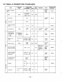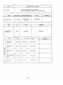
1
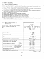
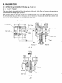
ROBIN AMERICA, INC.
ROSIN TO WISCONSINROBIN
ENGINE MODEL CROSS REFERENCE LIST
I
ROBIN
WISCONSIN ROBIN
SIDE VALVE
W 1-080
w1-145
W1-145V
W1-185
W1-185V
W 1-230
W 1-280
W 1-340
W 1-390
W 1-450V
EY2 1W
EY44W
EY 18-3W
EY25W
EY27W
EY08
EYl5
EY 15V
EY20
EY20V
EY23
EY28
EY3 5
EY40
EY45V
EY2 I
EY44
EY 18-3
EY25
EY27
OVERHEAD VALVE
WO1-115
wo1-120
WO1-150
WO1-170
wo1-210
WO1-250
WO1-300
WO 1-300v
WO1-340
WO 1-340V
WO 1-43OV
EHl1
EH12
EHl5
EH17
EH2 1
EH25
EH30
EH30V
EH34
EH34V
EH43V
TWO CYCLE
WTI-125V
EC13V
DIESEL
DY23
DY27
DY30
DY3 5
DY4 1
WRD 1-230
WRD 1-270
WRD 1-300
WRD1-350
WRDI-410
CONTENTS
Section
Title
1. SPECIFICATIONS
..........................................
Page
1
2 . PERFORMANCE . . . . . . . . . . . . . . . . . . . . . . . . . . . . . . . . . . . . . . . . . . .
2 - 1 Maximum
Output . . . . . . . . . . . . . . . . . . . . . . . . . . . . . . . . . . . . . .
2 - 2 Continuous Rated Output . . . . . . . . . . . . . . . . . . . . . . . . . . . . . . .
2-3 MaximumTorque a t Maximum Output .....................
2
3. FEATURES . . . . . . . . . . . . . . . . . . . . . . . . . . . . . . . . . . . . . . . . . . . . . . .
3
4 . GENERALDESCRIPTION of ENGINECONSTRUCTION . . . . . . . . . .
4 - 1 Cylinder. Crankcase . . . . . . . . . . . . . . . . . . . . . . . . . . . . . . . . . . . . .
4-2 Main Bearing
Cover
....................................
4 - 3 Crankshaft . . . . . . . . . . . . . . . . . . . . . . . . . . . . . . . . . . . . . . . . . . .
4 - 4 Connecting Rod and Piston . . . . . . . . . . . . . . . . . . . . . . . . . . . . . .
4-5 Camshaft . . . . . . . . . . . . . . . . . . . . . . . . . . . . . . . . . . . . . . . . . . . .
4-6 Valve Arrangement . . . . . . . . . . . . . . . . . . . . . . . . . . . . . . . . . . . . .
4-7 Cylinder Head . . . . . . . . . . . . . . . . . . . . . . . . . . . . . . . . . . . . . . . .
4 - 8 Governor . . . . . . . . . . . . . . . . . . . . . . . . . . . . . . . . . . . . . . . . . . . .
4 - 9 Cooling . . . . . . . . . . . . . . . . . . . . . . . . . . . . . . . . . . . . . . . . . . . . . .
4- 10 Lubrication . . . . . . . . . . . . . . . . . . . . . . . . . . . . . . . . . . . . . . . . . .
4-11
Ignition
.............................................
4-12 Carburetor . . . . . . . . . . . . . . . . . . . . . . . . . . . . . . . . . . . . . . . . . . .
4- 13 Air Cleaner . . . . . . . . . . . . . . . . . . . . . . . . . . . . . . . . . . . . . . . . . . .
4-14 Balancer . . . . . . . . . . . . . . . . . . . . . . . . . . . . . . . . . . . . . . . . . . . . .
4-15 Sectional View of Engine . . . . . . . . . . . . . . . . . . . . . . . . . . . . . . . .
3
.
2
2
2
3
4
4
4
5
5
5
6
6
6
6
7
7
7
8
DISASSEMBLY and REASSEMBLY . . . . . . . . . . . . . . . . . . . . . . . . . . . .
5 - 1 Preparation andSuggestion . . . . . . . . . . . . . . . . . . . . . . . . . . . . . .
5 - 2 Special Tool . . . . . . . . . . . . . . . . . . . . . . . . . . . . . . . . . . . . . . . . . .
5 - 3H o w T o
Disassemble . . . . . . . . . . . . . . . . . . . . . . . . . . . . . . . . . . .
5 - 4 How To Reassemble . . . . . . . . . . . . . . . . . . . . . . . . . . . . . . . . . . . .
10
10
11
20
6. ENGINE SPEED SETTING . . . . . . . . . . . . . . . . . . . . . . . . . . . . . . . . . . .
29
7 . MAGNETO . . . . . . . . . . . . . . . . . . . . . . . . . . . . . . . . . . . . . . . . . . . . . . .
30
5
7-1
7-2
7-3
7-4
10
Features . . . . . . . . . . . . . . . . . . . . . . . . . . . . . . . . . . . . . . . . . . . . .
30
..................................
Wiring Diagram . . . . . . . . . . . . . . . . . . . . . . . . . . . . . . . . . . . . . . . .
Checking Procedures . . . . . . . . . . . . . . . . . . . . . . . . . . . . . . . . . . .
30
Basic Theoryof T . I.C.
30
31
Section
.
Page
Title
. . . . . . . . . . . . . . . . . . . . . . . . . . . . . . . . . . . . . . . . . . . . 32
8 - 1Operation
and Construction . . . . . . . . . . . . . . . . . . . . . . . . . . . . . .
32
8 - 2 Disassemblyand
Reassembly .............................
33
9. STARTING MOTOR . . . . . . . . . . . . . . . . . . . . . . . . . . . . . . . . . . . . . . . .
35
9 - 1 Disassembly . . . . . . . . . . . . . . . . . . . . . . . . . . . . . . . . . . . . . . . . . . 35
9 - 2 Inspection andRepair
. . . . . . . . . . . . . . . . . . . . . . . . . . . . . . . . . . 38
9 - 3 Reassembly . . . . . . . . . . . . . . . . . . . . . . . . . . . . . . . . . . . . . . . . . . 41
10. BREAK-IN OPERATION O f REASSEMBLED ENGINE . . . . . . . . . . . . . 42
8
CARBURETOR
.
11 TROUBLESHOOTING ......................................
43
11-1 Starting Difficulties . . . . . . . . . . . . . . . . . . . . . . . . . . . . . . . . . . . . 43
11 -2 Engine Misfires . . . . . . . . . . . . . . . . . . . . . . . . . . . . . . . . . . . . . . . . 44
11-3 Enginestops .........................................
44
44
11- 4 EngineOverheats . . . . . . . . . . . . . . . . . . . . . . . . . . . . . . . . . . . . . .
11 -5 Engine Knocks . . . . . . . . . . . . . . . . . . . . . . . . . . . . . . . . . . . . . . . .
45
45
11-6 Engine Backfires through Carburetor .......................
12. INSTALLATION
...........................................
46
12-1 Installing . . . . . . . . . . . . . . . . . . . . . . . . . . . . . . . . . . . . . . . . . . . .
46
12-2 Ventilation . . . . . . . . . . . . . . . . . . . . . . . . . . . . . . . . . . . . . . . . . . .
46
46
12-3 Exhaust Gas Discharge . . . . . . . . . . . . . . . . . . . . . . . . . . . . . . . . . .
12-4 Power Transmission t o Driven Machines .....................
46
13. CHECKS and CORRECTIONS . . . . . . . . . . . . . . . . . . . . . . . . . . . . . . . . 47
14. TABLE of CORRECTION STANDARDS . . . . . . . . . . . . . . . . . . . . . . . . 48
53
15. MAINTENANCE and STORING . . . . . . . . . . . . . . . . . . . . . . . . . . . . . . .
53
15- 1 Daily Checksand Maintenance ............................
15-2 Initial 20 Hours Check . . . . . . . . . . . . . . . . . . . . . . . . . . . . . . . . . .
53
15-3 Every 50 Hours (10 days) Checks and Maintenance . . . . . . . . . . . . 53
15-4
15-5
15-6
15-7
-
.....
Every 100 200 Hours (Monthly) Checks and Maintenance
53
Every 500 600 Hours (Semiannual) Checks and Maintenance . . . 54
Every 1000 Hours (Yearly) Checks and Maintenance . . . . . . . . . . . 54
Preparation for Long Storage . . . . . . . . . . . . . . . . . . . . . . . . . . . . .
54
-
.
1 SPEC1F ICATIONS
Model
I
EY45V
Air-Cooled, 4-Cycle, VerticalShaft, Single Cylinder Gasoline Engine
TY Pe
90 mm x 70 mm (3.54" x 2.75")
Bore x Stroke
~~
445 cc (27.15 cu. in)
Piston Displacement
12 HP/3600r.p.m. (SAE Code-J607a)
Maximum Horse Power
2.5 kg-m/2600 r.p.m. (18.08 ft-lbs./2600 r.p.m.)
Maximum Torque
Counter-clockwise as viewed from P.T. 0. shaft side
Direction of Rotation
System
Forced Air Cooling Cooling
Oil Pump
Lubrication
Automobile OilSAE #20
Lubricant
- 30, Class SC
Horizontal Draft, Float Type
Carburetor
Automobile Gasoline
Fuel
Fuel Feed
Gravity Type
Governor
Centrifugal Flyweight Type
Flywheel Magneto Type (Solid State Ignition)
Ignition System
NGK BPMGA
Spark Plug
DC 12V-1.5A Battery Charge
AC12V-15W or 1OOW Lighting Coil (Optional)
Charging (Lighting) Capacity
Electric Starter (Recoil Starter: Optional)
Starting System
Approx. 35 kg (77.1 lbs.)
Dry Weight
41 5.5 mm ( 16.35")
Length
1
I Height
Dimensions Width
I
I
373.5
(14.7")
mm
(12.28")
mm
312
excluding
-1-
P.T. 0. Shaft
2. PERFORMANCE
2-7MAXIMUM
OUTPUT
The maximum output of an engine is such a standard poweras produced by the engine with its throttlevalve
fully opened after its initial break-in period when all the moving parts are properly worn in. Therefore, a new
engine may not produce the maximum output in the beginning because the moving parts are not in a properly worn-in condition.
2-2 CONTINUOUS RATED OUTPUT
The continuous rated output of an engine is such a power as produced by the engine when running continuously at an optimum speed, and most favorable from the viewpoint
of engine life and fuel consumption ratio,
with the governor in operation.I t is suggested, therefore, that whendesigning a driving system for any mechanism, with this engine as prime mover, the continous power requirement of that mechanism be kept below
the continuous rated output specified.
2 - 3 MAXIMUM TORQUE AT MAXIMUM
OUTPUT
These mean the maximum torque of the output shaft at the maximum outputof an engine.
PERFORMANCE CURVES
Kg-m
2.5
2.3
12
6
5
Revolution
-
r.p.m.
f
3. FEATURES
I . The cylinder and crankcase is a light weight one-piece aluminum diecasting. The dimensions
are as small
as those of a 10-horsepower engine.
2. The engine is powerful with a wide torque range from low speed tohigh.
3. The vibration-free design with twin balancer shafts.
4. A pointless electronic ignition system is adopted as standard, which makes the ignition system maintenance-free.' You will no longer be troubled by worn contact points or faulty sparking from wrong ignition
timing.
5. The engine employs a special cast iron cylinder liner, a forged steel crankshaft, mainball bearings at both
sides and forced spray lubrication by
durability.
oil pump for prolonged durability. All this adds up to improved
4. GENERAL DESCRIPTION of ENG NE CONSTRUCTIO
4 - 1 CYLINDER.CRANKCASE
The cylinder and crankcase is single piece aluminum
of special cast
diecasting. The cylinder liner, made
iron, is molded into the aluminum casting. The
intakeandexhaustportsarelocatedonone
side of
the cylinder.
Thecrankcase has afittingsurfaceontheoutput
shaft side, where the main bearing cover is attached.
(See Fig. 1 .)
Fig. 1
-3-
4-2 MAIN BEARING COVER
The main bearing cover is an aluminum diecasting, which is mounted on the output shaft side of the crankcase. Remove the main bearing
cover
to expose
the
inside of the engine inspection.
for
The main bearing cover also serves as an oil pan, with a trochoid oil pump, oil filler and oil drain plug. (See
Figs. 2 and 3.)
Fig. 2
Fig, 3
4-3 CRANKSHAFT
The crankshaft is forged carbon steel, and the crank
pin is induction-hardened.The output end of the
shaft has a crankshaft gear and balancer gear that are
pressed into position. (See Fig. 4.)
Induction Hardening
(Portion of Crankpin)
Crank Gear
(Press-fit)
Fig. 4
4 - 4 CONNECTING ROD and PISTON
Theconnecting rod is forgedaluminumalloy,and
its large and small ends serve as bearings. The piston
is an aluminum alloy casting, and carries
two compression rings and one oil ring. The piston pin hole is
offset from the center
of the piston to reduce hitting noise and improve durability. (See Fig. 5.)
Fig. 5
-4-
n
The camshaft is a hollow special cast iron integrally
molded with the camshaft gear. The governor plate
is riveted to it, and one end of.the camshaft has a
pin for driving the oil pump. (See Fig. 6 .)
Fig. 6
4-6 VALVE ARRANGEMENT
The intake valveis located at flywheel side of the
crankcase.
Hardalloy valve seats are moldedinthecylinder
block for added durability. (See Fig. 7.)
Exhaust
intake Valve
Fig. 7
4-7 CYLINDERHEAD
The cylinder head is an aluminum die casting, and
forms a Ricardo type combustion chamber with ample area for high combustion efficiency.
Fig. 8
-5-
4 - 8 GOVERNOR
The governor is a centrifugal flyweight type which
permitsconstantoperationatthe
selectedspeed
against load variations. Governor gear is installed on
the bearing cover, and it engages with the cam gear
after reassembling. (See Fig. 9.)
Fig. 9
4-9
COOLING
The cooling fans on the flywheel cool the cylinder and cylinder head by forced air cooling. Cylinder baffles
is provided for guiding the cooling air.
&
4- 10 LUBRICATION
Thetrochoid oil pump is mountedinside of the
main bearing cover.
Oil pump is driven by the camshaft to supply oil for
the rotating or sliding parts. (See Fig. 10.)
Camshaft
/
Oil Filter
Holder (Camshaft
Oil Pump (Inner)
Oil Pump (Outer)
Fig. 10
I
4-11 IGNITION
The ignition system is a flywheel magneto type with
ignition timing set at 23" before TDC. The magneto
is composed of a flywheel and ignition coil. The flywheel is mounteddirectlyonthecrankshaft,and
ignition coil on the crankcase. (See Fig. 1 1 .)
(For
further
details,
refer to page 30, Section
"7. MAGNETO".)
-6-
Ignition Coil
4-12 CARBURETOR
is employed.It has
been carefullyset after thorough teststo assure satisfactory start up, acceleration, fuel consumption, output performance, etc. (See Fig. 12.)
For construction and other details, refer t o page 32
Section "8. CARBURETOR".
A horizontaldraftcarburetor
Fig. 12
4-13 AIRCLEANER
'leaner
Case
Cleaner
Element
The air cleaner is a semicyclone type with double
elements. (See Fig. 13.)
~
Fig. 13
4-14 BALANCERS
Unbalanced moments of inertia that are generatedin
the verticalandhorizontaldirections
are balanced
bythetwobalancersthatrotate
1 to 1 withthe
crankshaft to effectively reduce vibration.
(See Fig. 14.)
Fig. 14
-7-
Cleaner Cover
4-15 SECTIONAL VIEW of ENGINE
Flywheel
/-(Cooling
Fan)
f
Ignition Coil
Housing
' Head
-8-
r
Tappet
Air Cleaner
Intake and
Exhaust Valve
Muffler
rSp
“Spark
1
Oil Filler
Starting Motor
-9-
Plug Cap
5. DISASSEMBLY and REASSEMBLY
5 - 1 PREPARATIONS and SUGGESTIONS
1 ) When disassembling the engine, memorize well the locations of individual parts so that they can be reassembed correctly. I f you are uncertain of identifying some parts, it is suggested that tags be attached to
them.
2) Have boxes ready t o keep disassembed parts by group.
3) To prevent missing and misplacing, temporarily assemble each group of disassembed parts.
4) Carefully handle disassembed parts, and clean them with washing oil.
5 ) Use the correct tools in the correct way.
5 - 2 SPECIAL TOOLS
For yourreference, the following table showsspecial tools for disassembling Robin Engines.
Part No.
Tool
Use
Applicalbe
Model
EY10,13,14
EY15,18,20
209 95004 07
Flywheel Puller
(with bolt)
For pulling off
Flywheel
EY25,27,28
EY33,35,40
EY44.45
EC05.07,lO
EC17,25,37
EY10, 13,14
207 95003 07
Valve Spring
Retainer
For mounting and
dismounting Valvc
Spring Retainer
and Retainer Lock
EY15,18,20
EY25,27,28
EY33,35,40
EY44.45
- 10-
Shape
5 - 3 HOW TO DISASSEMBLE
*Bolt length is the length from bolt endto the bottom surfaceof bolt head.
E
Order
Procedure
item
Remarks
Engine
(Oildrain plug)
Remove oil drain plug and discharge oil.
Muffler and
bracket
(1) Remove muffler bracket.
(2) Turn up heat deflector tabs, and remove
Be careful not to lose
gasket.
17 mm box wrench
10 mm box wrench
12 mm box wrench
nuts.
Muffler
- 11 -
Tool
+
Order
I
Governor lever
I
Procedure
item
Remarks
~
~~~
Memorize or mark
the governor spring
hooking position.
(1) Remove governor lever from shaft.
(2) Remove governor spring and governor rod
from governor lever.
I
I
Tool
10 mm box wrench
’
10 mm box wrench
(1) Remove speed control assembly from crankcase.
(2) Remove choke rod from speed control
assembly.
Control
Rod Spring
GoV
Choke R o d 1 5
\
Lever
Choke
ltrol
Governor Spring
I
Ylarburetor
Governor Lever
Fig. 15
- 12 -
,”-
Order
I
Procedure
Item
I
A i r cleaner
L
Remarks
Tool
(1) Remove wing nuts, cleaner cover, and element.
(2) Remove cleaner case.
10 mm wrench
Carburetor and (1) Remove support (elbow) bolt on crankcase
side.
intake manifold
( 2 ) Remove intake manifold nuts, and assembly
of intake manifold, carburetorand elbow
from engine.
(3) Separate carburetor and elbow from intake
manifold if necessary.
Disconnect breather
pipe at elbow side
end.
Oil filler
Be careful not to
lose O-ring.
(1) Remove clamp (oil filler).
( 2 ) Pull out oil filler from main bearing cover.
Clamp (Oil Filler)
10 mm box wrench
12 mm box wrench
12 mm box wrench
10 mm box wrench
.I#"-Wing
Nut
Washer
%Grommet
=.
-Cleaner Cover
Oil Filler
/Crankcase
Intake Manifold
- 13 -
1 Order I Item
I
Procedure
I 8 I Startingmotor I Remove starting motor.
I
9
Rotating
/ screen
II I
lo
Blower housing
and head cover
I
Remarks
Tool
1 12 mm box wrench
Remove rotating screeen and spacer.
12 mm box wrench
(1 j Remove blower housing.
(2 j Remove cylinder baffle.
(3j Remove head cover.
10 mm box wrench
1
-
14 -
I
I
I
I1
/
Order
Remarks
Item
Procedure
Tool
I
I
11
Igntion coil
Remove ignition coil from crankcase.
Be sure to remove
ignition coil f i s t .
10 mm box wrench
12
Flywheel and
lighting coil
(1) Remove nut from tip of crankshaft.
(2) Remove flywheel using flywheel puller.
(See Fig. 16.)
(Ring gear is located
inward of ignition
coil, so, if flywheel
is pulled out first,
case may become
broken.)
24 mm box wrench
(3) Remove charge coil. (See Fig. 17.)
Phillips screwdriver
Flywheel Puller
Fig. 17
Fig. 16
- 15 -
Order
13
Remarks
Item
Tool
Procedure
Cylinder head (1) Remove spark plug.
head.cylinder
( 2 ) Remove
14
Breather
(1) Remove breather cover.
( 2 ) Remove breather plate.
15
Intake and exhaust valves
(1)
. . Remove tappet cover.
(2) Using a valve spring retainer, remove
retainer lock from valve stem.
(3) Remove intake and exhaust valves.
(See Fig. 18.)
(4) Remove spring retainers and valve springs.
16
Main bearing
cover
(1) Remove
bolts.
(2) Remove main bearing cover by lightly tapping its side with a plastic hammer.
(See Fig. 19.)
"
I
wrench box
19 mm plug wrench
14 mm
Be careful of gaskets.
10 mm box wrench
Intake
and
exhaust
valves use the same
valve spring, retainer,
and retainer lock, but
in case of reusing
them, reassemble
them exactly as before.
10 mm box wrench
Valve spring retainer
careful not to
damage Oil
with PTO shaft
keyway.
.Be careful not to
lose crankshaft
and camshaft
adjusting spacers.
12 mm box wrench
.
B
e
/"-
I
I
Main Bearing Cover
,'
I
Fig. 19
Fig. 18
- 16-
Head Gasket
iap
Spark Plug
Valve Guide
Exhaust Valve
(Outer)
Q
Main Bearing Cove;
- 17 -
1
Order
-
Item
I
Procedure
Remarks
Balancers
(1) Turn crankshaft to top dead center.
( 2 ) Remove balancers. (See Fig. 20.)
Camshaft and
tappets
(1) Remove camshaft. (See Fig. 2 1 .)
(2) Remove tappets.
The tappets for intake and exhaust
valves are interchangeable, but in
case of reusing, reassemble exactly as
before.
Tool
-
12 mm box wrench
Blancer 1
Cran
Balancer 1 /
\
Balancer 2
11
Fig. 20
A d d
I
"
Fig. 21
- 18 -
\
Camshaft
Order
I
Item
~~
~~~~
I
I
Procedure
Remarks
~
~
19
Connecting rod (1) Turn up lock washer tabs and remove bolts.
(2) Remove connecting rod large end cap, push
piston up out of cylinder.
20
Crankshaft
Remove crankshaft by lightly tapping its flywheel end.
I
Tool
12 mm box wrench
Be careful notto
damge crankcase oil
seal.
a-
Spring Washer
@-
Washer
Connecting Rod Bolt
Connecting Rod
Rod Lock Washer
Connecting Rod
- 19-
5-4 HOW
TO REASSEMBLE
5 - 4 - 1 PRECAUTIONS IN REASSEMBLY
Everyandeachpartshouldbecleanedthoroughly.
Especially, pay utmost care and attention to the cleanliness of the piston, cylinder, crankshaft, connecting rod andbearings.
Scrape off carbons completely from the cylinder head and the piston
top; especially the carbon adhered
in the groove of the piston ring should be careflly and completely taken out.
Carefully check the lip portion of every oil seal. If faulty one is found, replace it without any hesitation.
Apply enough oil to the lip portion of the oil sea1 when reassembling.
Replace all the gaskets with new ones.
Replace the key, pin, bolt, nuts, etc. with new one, if necessary.
Whenever tightening torque is specified, conform to the specified figures.
Apply oil to the rotating parts and friction surfaces, when reassembling.
Check and adjust the clearances of various portions and then reassemble.
When some main portions are assembled in the course of reassembling, turn or move thegadgets by hand
and pay attention to the frictional noise and resistance.
5 - 4 - 2 MEASURINGCRANKCASE and
CRANKSHAFT
Bore the cylinder or take other steps as necessary to
meet the following specifications before
reassembling.
I
I
1
29;O.l
W (Crankshaft Pin Width)
+O 006
90 dia. -o:o16 rnrn
Bore
0
89.973 dia. -o.02 mrn
Piston Outside Diameter (In Skirt Thrust Direction)
I
I
I
I
Piston t o Cylinder a t Piston Skirt Thrust Face
Piston Ring Gap (To Ring
-
Second Ring)
TOP
Second
Oi I
Piston Ring Side Clearance in Grooves
Clearance between Connecting Rod
Large End and Crankshaft Pin
1
rnrn
~~
~~~
Clearance between Inside
and Outside Diameter
Side Clearance
0.01 1 L
- 0.053
L
- 0.3
0.050 - 0.082 L
- 0.3
0.1 L
L
0.11 L - 0 . 1 5 L
0.06 L 0.10 L
0.01 L 0.05 L
0.1 L
~~
Clearance between Connecting Rod
Small End and Piston Pin
0.010 L
Clearanc between Piston Pin and Piston Pin Hole
0.011 T
-
L
0.032 L
- 0.011
L
L: LOOSE
Table 1
-
20 -
T: TlGH
/"
5-4-3ASSEMBLING ORDER and
PRECAUTIONS
-
1)
Place
the
tappets
into
the
crankcase.
NO,TE: The intake and exhaust tappets are the
same, but markthem differently when
disassembling because o f different valve
clearances; and f i t them into their original place. Apply oilto the tappets beforehand.
2) Assemble thecrankshaftandcamshaftatthe
I
same time.
Fig. 22
NOTE: The timing marks are punchedon the
crankshaft gear and the camshaftgear.
Match these timing marks when assembling. (See Fig. 22.)
3) Assemble the connecting rod and the piston.
NOTE: The piston is offset. Assemble it so that
the square (0)on the piston topmatches
the @ MAG mark on the connecting.rod.
(See Fig. 23.)
CAUTION: When inserting thepiston pin and
fitting the clip on, be careful not to
damage the pistonsurface.
Fig. 23
4) Fit the piston rings on the piston.
NOTE: Each piston ring has a punched mark on its open end. These marks have to face upward when
assembled.
NOTE: When the piston rings are fitted in place, make sure that their ends are staggered as shown in Fig.
24. Be careful not to install them in the wronggroove. (See Figs. 24 and 25.)
Thrust Side
Top Ring (Chrome-plated)
Second Ring (Undercut)
Oil Ring (Chrome-plated)
(Assembly Type)
Fig. 24
Fig. 25
- 21
-
5 ) Install the piston and connecting rod assembly.
When installing theconnectingrodintoplace,
hold piston rings with the ring guide as shown in
Fig. 26 (if no ring guide is available, keep pressing the piston ring, with finger tips and gently
tap the top of the piston with a wooden
piece or
the like to push it in), and check that the
symbol 8 or the mark “MAG” on the connecting rod
is in the direction of the flywheel magneto.
iston Ring Guide
NOTE: Applyenough o i l t othe pistonrings, connecting rod plain bearings, and cylinder
wall before reassembling.
NOTE: The open ends o f the piston rings must
be 90” apart from oneanother on the
piston periphery.
NOTE: The clearance betweenthe piston and
cylinder must be measured at the piston
skirt thrustsurface.
(Magneto Side)
Fig. 26
6) Connecting rod tightening
Match the mark on the large end cap with that of the connecting rod large end, and install the large end
cap.
Bolts: 8 x 46 mm
Tightening torque: 250 300 kg-cm
Use a new lock washer and be sure to bend the tabs.
-
7) Main bearing cover subassembly
Assemble the governor shaft, governor yoke,
bearing cover.
oil pump, holder (camshaft), and oil filter with the main
NOTE: Be careful not todamage the oilseal when installing the governorshaft.
NOTE: Remove dust, chips, etc. from the inside of the pump housing and apply engine oil to it before
installing theoil pump.
Holder (camshaft) bolts: 6 x 25 m m with washer and spring washer
Holder (camshaft) tightening torque: 7 0 90 kg-cm
-
- 22 -
8) Sideclearancemeasuring
Adjust the side clearances of the crankshaft and camshaft with the adjusting collars. Measure
A, B , D,
and E shown in Fig. 27, and select adjusting collars so that the side clearances of both the crankshaft
and camshaft will be 0 t o 0.25 mm.
NOTE: C indicates gasket thickness. Calculate it as 0.25 mrn.
NOTE: Three kinds of adjusting collars- 1.05 mm, 1.2 rnrn, and 1.35 mrn thick-are available for both
the crankshaft and
camshaft.
T: Thickness of the adjusting collar
T = E - D + (0 0.25)
-
T=B
Fig. 27
- 23 -
-
- A + (0 0.25)
9) Balancermounting
Move the piston to the top dead center.
Engage balancer 1 with the crankshaft, and balancer 2 with balancer 1. (See Fig. 28.)
Match the match marks as shown
in Fig. 28.
/-
As viewed from drive shaft side.
Balancer Gear
Match Marks
Balancer 1
Fig. 28
10) Main bearing cover mounting
.Fit the governor sleeve on the camshaft; install the adjusting collars selected in Step8), and install the
main bearing cover assembly that was readied
in Step 7).
.Move the piston to the top dead center, align the groove of the oil pump shaft that is installed in the
main bearing cover with the camshaft holder groove as shown in Fig. 29, and mount the main bearing
cover.
Align the direction of oil pump shaft groove
with the groove on the holder (camshaft).
NOTE: Replace the gasket (main bearing cover) with a new one.
NOTE: Be careful not to damage the oil seal.
Bolts: 8 x 45 mm with washer and spring washer
Tightening torque: 170 190 kg-cm
-
-
24 -
,"--
*Intake and exhaustvalve specifications are as
follows:
Guide
VALVE and VALVE GUIDE CLEARANCE
~~
~~
A-VALVE FACE ANGLE
45O
B-SEAT ANGLE
45O
C-GUIDE INSIDE DIA.
8dia.
+0.036 mrn
INTAKE
-0 030
8 dia. -o:055 mm
E XH UAST
-0.070
8 dia. -o.090 mrn
D-VALVE STEM OUTSIDE DIA
MAXIMUM ALLOWABLE
CLEARANCE BETWEEN Cand D
INTAKE
0.030 L
0.070 L
EXHAUST
-
0.091 L
0.126 L
L: Loose
Table 2
.TAPPET CLEARANCE ADJUSTMENT
Turn the crankshaft to compression TDC, and
check the tappet clearance as follows.
Clearance: 0.08
- 0.12 mm when cold
If the clearance is too small, slightly grind the
end of valve stem.
Fig. 30
- 25 -
"Intake and exhaust valve installation
Apply oil to the
valve stems, and install the
valves securely byusing the valve spring retainer and pliers. (See Fig. 3 1 .)
After their installation, check the tappetclearance again.
Intake/Exhaust Valve
Fig. 31
12) Install the gasket and tappet cover.
13) Install breather plate and breather plate with gaskets.
NOTE: Make sure to use the correctgaskets.
14)Cylinderhead
Replace the head gasket with a new one.
NOTE: The edge-folded side o f the gasket must face the cylinderhead.
Head nuts: 10 mm flange nuts
Tightening torque: 350 400 kg-cm
-
15)Sparkplug
Tightening torque: 120
- 150 kg-cm
16) Electricalparts
a) Lighting coil
NOTE: Be sure to clamp the wire to prevent i t con tact with the flywheel.
6 x 20 m m screw and washer assembly
b)
Flywheel
Clean the dust or oil from the tapered portion of the crankshaft and flywheel, and install the flywheel.
NOTE: Install the flywheel before the ignitioncoif.
Tightening torque: 800
- 1000 kg-cm
c>Ignition coil
Adjust the clearance (air gap) between
coil.
the ignition coil and flywheel, and then tighten the ignition
Air gap: 0.5 mm
d)Startermotor
8 x 30 rnm reamer bolts with washer and spring washer
Tightening torque: 160 200 kg-cm
-
- 26 -
17) Blower housing and head cover
Install head cover, blower housing and cylinder baffle.
18) Rotatingscreen
Mount the rotating screeen with spacer.
8 x 50 mm bolts with washer and spring washer
Tightening torque: 160 200 kg-cm
-
19) Oilfiller
Insert the oil filler into the main bearing cover, exercising care not to damage the O-ring at the bottom
of the oil filler. Fasten the top of the
oil filler with the oil filler clamp.
20) Intake manifold, carburetor, elbow, and air-cleaner
.Temporarily fasten the intake manifold, carburetor, elbow, air-cleaner, etc. and make sure that these
parts are properly positioned relative to one another. Then tighten thebolts and nuts.
@Besure t o use the correct gasket on each flange. (SeeFig. 32.)
I TYPES of GASKETS and MOUNTING POSITIONS I
Intake
Insulator
Carburetor
Elbow
Fig. 32
- 27 -
a) Intakemanifold
b) Insulator
Be mounting
careful
itsof direction.
Intake
Manifold
Carburetor
SideSide
Intake manifold side
Carburetor side
c) Carburetor
*Pay attention to the types
of gaskets on
the front and back.
.Install the governor rod, rod spring, and
choke rod.
d) Elbow and support (elbow)
Install the breather pipe between the crankcase and elbow.
Fig. 33
e)Air-cleaner case
Place the air-cleaner case on the elbow and
intakemanifold,checkthatit
is properly
positioned relative to them, and tighten it.
f ) Cleaner element, cleaner cover
2 1) Governor lever and speed control
a) Governor lever
Hook the governor rod and rod spring to the end
governor shaft.
of the governor lever, and install the lever on the
b) Speed control, governor spring
Hook the choke rod to the choke lever. Install the governor spring on the governor lever and speed
control.
22) Governorset
Pull the speed control lever in the high speed directim, fully open the carburetor throttle
the governor shaft clockwise all the way, and tighten the governorlever bolt.
valve, turn
NOTE: Theengine speed setting procedure is described in a separate section.
23) Muffler
Replace the muffler gasket with a new one, and install the muffler and muffler bracket.
Muffler nuts: M 8 flange nuts (stainless steel)
Tightening torque: 180 220 kg-cm
-
After tightening the flange nuts, bend the tabs of the lock washers for the heat deflector to prevent the
nuts from turning loose.
- 28
-
6. ENGINE S
6-1 CHOKE and SPEED ADJUSTMENT
Operate the engine at no-load. Then, turn speed control
lever toward “CHOKE” position until it just contacts the choke/R.P.M. adjusting screw on choke lever (do not move choke
lever.).
To adjust the “CHOKE” start position and
HIGH speed operating R . P . M . , use a tachometer or revolution
counter. Turn the adjusting screw in or out against the speed controllever until the desired no load operating
speed is obtained. This same positionwill be the start of the ‘CHOKE’ operation.
6 - 2 TO INSTALL REMOTE CONTROL WIRE
1. Use a control wire suitable for
hole.
a .098“ (2.5 mm) diameter wire hole and .236“ ( 6 mm) diameter casing
2. Install control wire to engine
secure in place.
by control wire bracket.
Usepliers and pinch bracket around
3. Insert the end of control wire into the speed control lever.
4. Place speed control lever in “LOW SPEED” position and tighten control wire lockscrew.
Governor Lever
Fig. 34
- 29 -
casing to
7 . MAGNETO
The pointless electronic ignition magneto consists of a flywheel andan ignition coil.
7 - 1 FEATURES
This system is outer coil type without pulser and is called T.I.C. (Transistor igntion circuit type). To the
EY45V engine this T. I . C. is equipped as standard parts.
is completely free from
Being different from the breaker point type ignition system this brand-new system
such troubles as starting-up failure owingto dirty, burnt or corroded point
surface, reduction of ignition efficiency being caused by moisture, rough surface of breaker point and incorrect timing resulted from
worn
mechanical parts.
7 - 2 BASIC
THEORY
of T.I.C. (See Fig.
35.)
Ignition Coil
Resister
T.I.C. (Transistorigntiontype)consistsofthe
flywheel andignition coiI with built-in transistor;and
’5
m
3
its basic theory is as follows:
U
E
tion 1)
2
Q
on theprimarysideoftheignition
coil, andthe
E
m
.-In
electriccurrent A flows. A turnsthepowertran3
a
sistor “ON” and the electric currentB flows.
2) The flywheel goes round further, and at the time
of ignition,
electric
the
current
C flows
turn
to
Fig. 35
the signal transistor “ON” t o allow current D.
A t this moment the electric current B, passing through the power transistor, is abruptly shut; and as a result, the high voltage electricity is generated on the secondary side of the ignition
coil and it produces
sparks at the plug.
L
\I)
c.l
v)
(D
L
7-3 WIRING DIAGRAM
The following parts are not supplied witheingine as standard equipments.
STOP SWITCH
STARTER SWITCH
MAGNETIC
SWITCH
spARKpLuG?JB
l *‘c5
12V BATTER Y
AC 12V LAMP
SWITCH
.+- - ““STOP
67” 1
IGNITION
COIL
STARTER
L”I
77)77.
BATTERY
RED
SWITCH
(AC SOURCE)
GREEN/
WHITE
NOTE: AC source is for 12V, lOOW load.
The lighting coil is optional.
and
maximum
loads for the A C
NOTE: Rated
source are 80W and 1OOW respectively.
NOTE: Wires indicated by dotted lines are not
supplied with engine.
I
I
I
0
.I
LAMP
(AC12V-1OOW)
7/3m
- 30 -
12v
Fig. 36
/
.-
7 - 4 CHECKINGPROCEDURES
-
MEASURING RESISTANCES
7 - 4 - 1 IGNITION COIL
1) Primary Side
n
Note: The following resistance
values are measured a t 20°C.
Tester
Between stop lead and core
i"GZZd
2) Secondary Side
Between high tension cord
and core
7 - 4 - 2 LAMP COIL and CHARGECOIL
1) Charge Coil
Tester
Between GreedWhite cord and
GreedWhite cord
10.9
- 1.3a 1
\
GreedWhite
(Optional)
2) Lamp Coil
Tester
Between red cord and core
1-
-
31 -
8. CARBURETOR
8 - 1 OPERATION and CONSTRUCTION (See Fig. 37 and 38.)
8 - 1 - 1 FLOAT SYSTEM
The float chamber is located just below the carburetor body and, with a float and a needle
valve, maintains a
constant fuellevel during engine operation.
The fuel flows from the fuel tank into the float chamber through needlevalve. When the fuel rises t o a specific level, the float rises; and when its buoyancy and fuel pressure are balanced, the needlevalve closes to shut
off the fuel, thereby keeping the fuel at the predeterminedlevel.
Throttle Valve
I
Nozzle
Pilot Outlet
Air J e t
Fig. 37
FI
Needle Valve
Fig. 38
-
32 -
D
b
8-1 - 2 PI LOT SYSTEM
The pilot system feeds the fuel to the engine during idling and low-speed operation.
The fuel is fed through the main jet to the pilot jet,where it is metered, and mixed with the air metered by
the
pilot
air jet.
The fuel-air mixture is fed to the engine through the pilot outlet and the
by-pass.
At idling speed, the fuelis mainly fed from the pilot outlet.
8 - 1 - 3 MAIN SYSTEM
The main system feeds the fuel to the engine at medium- and high-speed operation.
The fuel is metered by the main jet and fed to the main nozzle. The
air metered by the mainair jet is mixed
with the fuel through the bleed holes in the main nozzle, and the mixture is atomized out of the main bore.
It is mixed again with the air taken through the air cleaner into an optimum fuel-air mixture, which is supplied to the engine.
8 - 1 - 4 CHOKE
The choke is used for easy start in the cold season. When the starter is operated with a closed choke, the
negative pressure applied to the main nozzle increases and draws much fuel accordingly; thus easily start up
the engine.
8 - 2 DISASSEMBLY and REASSEMBLY
Apart from mechanical failures, most of carburetor troubles are caused
by an incorrect mixing ratio, which
may arise mainly due to aclogged up air or fuel passage in jets, or fuellevel variations. In order to assure proper flow of air and fuel, the carburetor must be kept clean at all times. The carburetor disassembly and reassembly procedures are as follows: (See Fig. 39.)
8-2-1
THROTTLE
SYSTEM
1) Remove the Philips screw ( 5 ) and throttle valve
(4), and pull out the throttle shaft(9).
2) Thespring ( 1 2) can be taken out by removing
the throttle stopscrew (1 3).
*Exercise care not to damage throttle valve ends.
8 - 2 - 2 CHOKESYSTEM
1) RemovethePhilips
screw (2) and choke 'valve
( 3 ) , and pull out the choke shaft(7).
2) When reassemblingthechokeshaft,makesure
that the cutout in the choke valve faces the main
air jet.
Meantime,whenreassemblingsetthe
rings (8)
and (1 4) at the right position.
8 - 2 - 3 PILOT SYSTEM
1 ) Remove thepilotjet
( 6 ) , using correcttoolto
avoid damage to it.
2) Reassembly
Tighten the pilot jet securely. Otherwise, the fuel
tion.
ine
causingleak, may
- 33 -
Fig. 39
8-2-4 MAINSYSTEM
1 ) Remove the bolt (21) and take out float chamber body (23).
2) Fromthebody
(1) removethemainnozzle
( 1 8), andthenremovethe
main jet (20) fromthemain
nozzle (1 8).
3) Reassembly
a) Fasten the main jet securely to the body. Otherwise, the fuel may become too rich and cause engine
malfunction.
b) The bolt tightening torque is 70 kg-cm.
/"-
8 - 2 - 5 FLOAT SYSTEM
1) Pull out the floatpin ( 1 6) and remove the float ( 1 7) and needle valve (24). If the needle valve need be replaced, replace it with rubber needle.
Caution: When cleaning the jets, use neither a drill nor a wire (because of possible damage of the orifice
which will adversely affect fuel flow). Be sure to use compressed air to blow them clean.
2) When removing the needle valve and flots, gently tap the reverse side using the rod more slender than the
float pin and remove because the floatpin is calked to the carburetor body.
/"
-
34 -
9. STARTING MOTOR
9- 1 DISASSEMBLY
1) Remove 5 mm terminal nuts. (2 pcs.)
Fig. 40
2) Remove 5 mm through bolts. (2 pcs.)
y'
3) Remove terminal bush.
3
Fig. 41
4) Remove rear cover.
4
Fig. 42
- 35 -
Remove 4 mm Screws. (2 pcs.)
Remove Brush Holder.
The brush holderis disassembed by removingthe
4 mm screws. (2 pcs.)
Remove the TerminalBush No. 2.
I
Fig. 43
8) YokeAssembly
Remove yoke assembly.
Fig. 44
9) The pinion stopper clip is removed with a stanis
dardscrewdriver
while thepinionstopper
pushed toward the pinion.
A \ "
"
\I
1
Fig. 45
- 36 -
10) Disassemblepinion
stopper 10, pinion return
spring 1 1 and pinion assembly 12.
12
10
Fig. 46
11) Disassemble armature 13, thrust washer 14 and
front cover 1 5.
Fig. 47
1) The 5 mm Terminal Nuts (2 pcs.)
2) "M" Terminal Bush No. 1
3) The 5 mm Through Bolts (2pcs.)
4) The RearCover
5) The 4 mm Screws ( 2 pcs.)
6)
The Brush Holder
7) "M" Terminal Bush N o . 2
8) Yoke Assembly
9) The Pinion Stopper Clip
IO)
PinionStopper
11) PinionReturn Spring
12) PinionAssembly
13) Armature
14)
Thrust Washers
15) Front Cover
a
(4pcs.)
5
6
4
Fig. 48
- 37 -
9 - 2 INSPECTION and REPAIR
9 - 2 - 1 ARMATURE
1) Check the diameter of the commutator.
I f theoutsidediameter
of thecommutator is
smallerthanthelimit,thenreplacearmature
with a new one.
Standard (New)
30 m m
Limit (Used)
29 m m
Fig. 49
2) Continuity Test for the Armature Coil
Use a tester to check for continuity between parallel points on the commutator.If there is continuity, the armatureis good.
Tester
N o continuity: (broken coil)
Replace the armature unit.
Fig. 50
3) Insulation Test for the Armature Coil
Use a tester to check for continuity between a
point on the commutator and the shaft
or the
core. If there is no continuity, the armature is
I
Tester
good.
Continuity Exists: (Short circuited coil)
Replace the armature.
Fig. 51
- 38 -
4) Check for Surface Distortion on the Armature
and the Commutator
Use a dial gauge to measure the distortion of the
outsidesurfaces of thearmaturecoreandthe
commutator. If it is above the limit, then repair
or replace it.
Core
(mm)
I
Fig. 52
5 ) Check the Surface of the Commutator
Ifthecommutatorsurface
is rough, polish it
with fine sandpaper(# 500 600).
-
Fig. 53
6) Check the Depth of the Insulating Material from
the Commutator Surface
If the depth of the insulating material from the
commutator segments is less than the limit, repair it by filing it down.
0.5
Insulator
Correct
Limit (Used)
0.5 0.8
0.2 (Min.)
-
Incorrect
Fig. 54
- 39 -
0.8 mm
Commutator
Segments
(mm)
Standard (New)
-
Measure the length of the brushes and if they are
shorter than the limit, replace them.
Limit (Used)
Standard (New)
I
I
12.5 mm
9 mm
1
Brush
I
Fig, 55
9-2-3BRUSH HOLDER
1) Insulation Test for the Brush Holder
Check for continuity between the brush holder's
top (positive side) and its base (negative side). If
there is n o continuity, then it is good.
Continuity Exists: (Insulation failure)
Replace brush holder.
Fig. 56
2) Inspection of the Brush Springs
Check the return forceof the brush springs.
r
Normal force (kg)
1.4
- 1.8
4k
Fig. 57
- 40 -
9-2-4PINION CLUTCH
Inspection of the Pinion Clutch
Rotate the pinion manually. While rotating it in the
direction of normal operation, smoothly reverse the
direction of rotation to confirm thatit locks.
In the event of any irregularity, replaceit.
Fig. 58
9-3 REASSEMBLY
Reassembly is in the reverse order of disassembly, however, please note the following points.
The Places to Apply Grease:
The sliding surfaces of the pinionand the shaft’s spline.
The metals holding the shaft at the frontand rear covers.
- 41 -
IO. BREAK-INOPERATION
of REASSEMBLEDENGINE
*
An overhauled engine must be operated at low speedto break-in the parts. A thorough break-in is indispensable particularly when the cylinder, piston, pistonrings or valves are replaced with new ones.
The recommended break-in schedule is shown below.
LOAD
SPEED
TIME
LOAD
2,500 rpm
10 minutes
NO LOAD
3,000 rpm
10 minutes
NO LOAD
3,600 rpm
10 minutes
4.5HP
3,600 rpm
30 minutes
9.OHP
3,600 rpm
60 minutes
EY45V
NO
- 42
-
B
The following three conditions must be satisfied for satisfactory engine start.
1.Thecylinderfilledwith
a properfuel-airmixture.
2. An appropriate compression in the cylinder.
3. Good sparks at the correct time to ignite the mixture.
The engine cannot be started unless these three conditions are met. There are also other factors which make
engine start difficult, e.g., a heavy load on the engine when it is about to start at low speed, and a high back
pressure due to a long exhaust pipe, justto say a few.
The most common causes of engine troubles are given below:
111-1 STARTING DIFFICULTIES
1 1 - 1 - 1F U E L
SYSTEM
N o gasoline in the fuel tank; or the fuel cock
is closed.
The carburetor is not choked enough, particularly when the engineis cold.
Water, dust or gum in the gasoline blocks the fuel flowto the carburetor.
Inferior grade gasoline or poor quality gasoline is not vaporized enough to produce the correct fuel-air
mixture.
The carburetor needle valve is held open by dirt or gum. This trouble can be detected as the fuel flows
out of the carburetorwhen the engone is idling. (Overflow)
This trouble may be remedied, depending on cases, by lightly tapping the float chamber with the grip of
a screwdriver or the like.
If the carburetor overflows, excessive fuel runs into the cylinder when starting the engine, making the
fuel-air mixture too rich to burn. If this happens, remove the spark plug,
and turn the starting pulley a
few turns in order to let the rich fuel-air mixture out
of the spark pulg hole into the atmosphere. Keep
the carburetor choke open during this operation. Dry the spark plug well, screw it into place, and try to
start again.
11- 1 - 2 COMPRESSION SYSTEM
If starting difficultes and loss of power are not dueto the fuel system or ignition system, the followings must
be checked for possible lackof compression.
1) Engine inside is completely dried up because of a long period of non-operation.
2) Loose or broken spark plug. This causes a hissing noise made by mixture gas running out of cylinder in
compression stroke during cranking.
3) Damagedheadgasket
or loosecylinderhead.Asimilarhissingnoise
is producedduringcompression
stroke.
4) Incorrect Tappet Clearance
If the correct compression is not obtained even after remedying the above, disassemble the engine and
check further as follows:
a) Valve stuck open due to carbon or gum o n the valve stem.
b) If the piston rings are stuck on the piston, remove the piston and connecting rod from the engine,
and clean, remedy or replace the parts.
- 43 -
1 1 - 1 - 3 ELECTRICAL SYSTEM
Check the followings for lack of sparks.
1) Leads of the ignition coil, spark plug or contact breaker disconnected.
2) Ignition coil damaged and shorted.
3) Spark plug cable wet or soaked with oil.
4) Spark plug dirty or wet.
5) Spark plug electrode gap incorrect.
6) Spark plug electrodes are connected or bridged.
7) Incorrect spark timing.
11- 2 ENGINGE MI FIRES.
1)
2)
3)
4)
5)
6)
Incorrect spark plug electrodge gap. Adjust it to anywhere between0.6 and 0.7 mm.
Ignition cable worn and leaking.
Sparksweak.
Ignition wire connections loose.
Water in gasoline.
Insufficientcompression.
11-3 ENGINE STOPS.
1)
2)
3)
4)
5)
6)
Fuel tank empty. Water, dirt, gum, etc. in gasoline.
Vapor lock, i. e., gasoline evaporating in the fuel lines due to overheat around the engine.
Vapor lock in the fuel linesor carburetor due to the use of too volatile winter gas in the hot season.
Air vent hole in the fuel tank cap plugged.
Bearing parts seized due to lack of oil.
Magneto or ignition coil faulty.
11- 4 ENGINE OVERHEATS.
1)
2)
3)
4)
5)
6)
7)
8)
9)
Crankcase oil level low. Add oil immediately.
Spark timing incorrect.
Low grade gasoline is used, or engine is overloaded.
Cooling air circulation restricted.
Cooling air path misdirected causes loss of cooling efficiency.
Cylinder head cooling fins clogged up with dirt.
Engine operated in an enclosed space without fresh supply of cooling air.
Exhaust gas discharge restricted, or carbon deposits in the combustion chamber.
Engine running on low-octane gaoline detonates due to heavy load at low speed.
- 44 -
,
"
-
11-5 ENGINEKNOCKS.
-
1)Low-qualitygasoline.
2) Engineoperatingunder
heavy load at low speed,
3) Carbon
or
lead
deposits
in
the
cylinder
head.
4) Spark timing incorrect.
5) Loose connecting rod bearing due to wear.
6) Loose piston pin due to wear.
7) Cuases of engine overheat.
11 - 6 ENGINE BACKFIRES through CARBURETOR.
1) Water or dirt in gasoline,o r low-grade gasoline.
2 ) Intake valve stuck.
3) Valves overheated, or red-hot carbon particles in the combustion chamber.
4) Enginecold.
c
- 45 -
12. INSTALLATION
Engine life, ease of maintenance and inspection, frequency of checks and repairs, and operating cost all dependonthe way in whichtheengine is installed.Carefullyobserve
thefollowinginstructionsforinstalling
the engine.
,
"
-
12-1
INSTALLING
When mounting the engine, carefully examine its position, the method of connecting it
t o a load (machine),
the foundation, and the mehtod of supporting the
engine.
When determining its mounting position, in particular, make sure that gasoline and oil can easily be supplied
and checked, the spark plug can easily be checked, the air cleaner can easily be serviced, and that the oil can
easily be discharged.
12-2 VENT1 LATION
Fresh air is necessary for cooling the engine and burning the fuel.
In case where the engine is operated under a hood or in a small room, temperature rise in the engine room
cancausevaporlock,
oil deterioration,increased oil consumption, loss of power, piston seizure, shorter
engine life, etc., making it impossible to operate the engine properly. It is necessary, therefore, to provide a
duct or baffle to guide cooling
air to the engine t o prevent recirculation of he hot air used for engine cooling,
and temperature rise of the load (machine).
Take steps as necessary to keep the engine room temperature below 50°C even in the hottest period of the
year.
12-3EXHAUST
GAS DISCHARGE
Exhaust gas is noxious. When operating the engine indoors, be sure to discharge the exhaust gas outdoors. If
a long exhaust pipe is used in such a case, the internal resistance increases causing loss of engine power. Thus
pipe inside diameter must increase in proportion to exhaust pipe length.
Exhaust pipe: Less than 3 m long, pipe inside diameter 25 mm,
Less than 5 m long, pipe inside diameter 30 mm.
12-4 POWER TRANSMISSION to DRIVEN MACHINES
12-4-1 B E L T D R I V E
Take the following notes into consideration.
* V-belts are preferable t o flat belts.
* The driving shaft of the engine must be parallel to the driven shaft of the load.
* The driving pulley of the engine must be in line with the driven pulley of the load.
* Install the engine pulley as close to the engine as possible.
* I f possible, span the belt horizontally.
* Disengage the load when starting the engine.
I f no clutch is used, use a belt tension pulley or the like.
1 2 - 4 - 2 F L E X I B L E COUPLING
When using a flexible coupling, runout and misalignment between the driven shaft and engine shaft must be
minimized. Runout and misalignment tolerance are specified by the coupling manufacturer.
- 46 -
,
"
-
13. CHECKS and CORRECTIONS
After disassembling and cleaning the engine, check and repair, if necessary, according to the correction table.
The correction table apolies whenever the engines are repaired. It
is important for the servicemen to
be
familier with the contents of this table. Correct maintenance is recommended by observing the correction
standards specified.
The meanings of the terms used in the correction table are as follows:
1) Correction
Repair, adjustment or replacement of any engine parts.
2) CorrectionLimit
The limit on wear, damage or functional deterioration of engine parts beyond which normal engine performance cannot be expected without repairing such parts.
3) Use Limit
The limit beyond which parts can no longer be used in respect of performance or strength.
4) StandardDimensions
The design dimensions of new parts minus tolerance.
5) CorrectionTolerance
Tolerance on the dimensions of engine parts refinished or adjusted.
. . ..
..
- 47
-
14. TABLE of CORRECTION STANDARDS
lTEM
STANDARD
SIZE
1
T USE
CORRECT1
LIMIT
TOLERANCE
Flatness of cylinder
head
0.05
+
ZORRECTIOfl
METHOD
Correct
Surface
Bore
90 dia.
Dif. between
max. & min.
0.1 5
0.65
+0.006 -0.016
Roundness
0.01
Cylindricity
0.015
Valve seat contact
width
plate,
Boring
I
Correct
2.5
1 .2 -1. .5
Valve guide I.D.
+0.036
0
8 dia.
0.1 5
0.1 5
O.D. at skirt, in
thrust direction
(incl. over size)
B 0.25
C 0.5
Width of ring
groove
gauge
Replace
1
I
STD 89.973 dia.
B
90.223dia.
C
90.473dia.
Top, 2nd: 2.5
Oil: 4
Piston pin hole
portion
0
-0.02
-0.1
-0.1
Micrometer
Replace
Top +0.06 +0.04
2nd +0.04 +0.02 0.15
Oil +0.04 +0.02
0.1 5
Vernier
calipers
Replace
Cylinder
gauge.
Micro-
Replace
Feeler
gauge
Replace
---
+0.002
- 0.011
20 dia.
Clearance between
piston and cylinder
0.053
Clearance between
pisition ring and
ring groove
0.035
- 0.011
Top 0.15
2nd 0.10
Oil 0.05
0.035
-
--
0.1 1
0.06
0.01
-
'
0.25
0.1 5
0.1 5
F i t between piston
and piston pin
Cylinder
gauge.
Micrometer
0.01 1 T
0.011 L
:.q0..
Ring gap
- 0.1
Oil
Top, 2nd: 2.5
Ring width
Oil: 4
Top -0.07
2nd -0.04
Oil +0.01
1.5
Max. cylinder dia.
and
piston dia.
at skert in
thrust
direcmeter
tion
1.5
Replace
-
- -0.0s
- -0.OE
- -0.01
- 0.1
- 48 -
-0.1
Mircrometer
F
1
ITEM
STYFtRD
1
20 dia.
Piston pin O.D.
'
USE
TOLERANCE
LIMIT LIMIT
CoRRECTlyN
0
1
-
-0.009
+0.016
3 8 dia.
Clearance between
rod large end I.D.
and crankpin
Small
end
I.D.
20 dia.
Clearance between
small end I.D.
0.082
+0.023
-
+0.010
0.1
-
0.032
- 0.3
0.06
Distance between
and large end
small end bores
120
Crankpin
O.D.
-0.03
0.1
3 8 dia.
-0.050
TOOL
I
CORRECTION
METHOD
-0.03
0.1
I
1
I
I
Cylinder
gauge
Replace
Cylinder
gauge,
Micrometer
Replace
0.08
0.08
0.1 2
0.1 2
Cylinder
gauge,
Micrometer
Replace
1 .o
1 .o
Feeler
gauge
Re-machine
or Replace
0.1
0.1
0.15
- -0.066
I
0.2
*0.1
0.1 5
0.5
1
and Dial
I
or Replace
Test bar
1
Micro-
Re-machine
or Replace
Crankpin O.D.
roundness
Less than 0.005
Micrometer
Re-machine
or Replace
Crankpin O.D.
cylindricity
Less than 0.005
Micrometer
Re-machine
or Replace
Less than 0.01
Dial
gauge
Re-machine
or Replace
I
I
Crankpin O.D.
parallelism
Crankshaft
journal O.D.
I
PTO Side
Magneto Side
35 dia.
Intake
height
0
-
Parallelism between
large end
small end bores
and
-
0.050
0.01 0
Large end side
clearance
I
t
I
Large end I.D.
REMARKS
-0.003
0.05
-0.014
0.05
AO.1
-0.25
-0.25
0.05
0.05
Exhaust 35.5
Journal O.D.
PTO Side
Magneto Side
20 &a.
1
I
36
Cam lobe
I
-0.020
- -0.033
- 49 -
1
1
I
1
I
Micro-
meter
Micrometer
~~~l~~~
Replace
CORRECTION
TOLERANCE
LIMIT
STANDARD
ITEM
SIZE
LIMIT
I
46
Clearance between
stem and guide
Vernier
calipers
Replace
Square
feeler
WJge
Replace
Micrometer
Replace
Feeler
gauge
Correct
-0.5
Vernier
calipers
Replace
- 0.5
Vernier
calipers
Replace
,.o
1
Intake
Exhaust
,-
For total
length
-0.030
8 dia.
Exhaust 8 dia.
CORRECTION
METHOD
-1.5
Squareness
Intake
1
REMARKS
I
Free length
Valve stem O.D.
I
- 0.055
1
-0.070
1
-0.096
0.030-0.091
0.070
-
0.126
-0.15
0.3
0.3
Tappet clearance
middle
At
I
Clearance between
groove and retainer
Stem
length
end
0.04 -0.1 5
1
Total length
-0.5
5.3
57
I
I
I
I
I
Clearance between
stem and guide
I
1
0.2
0.2
II
Replace
i 114
Pilot screw
unscrew
Spark plug
0.025-0.062
Cylinder
gauge &
Micrometer
I
BPMGA
NGK
I
I
1
Feeler
gauge
Adjust or
replace
* 3"
Timing
tester
Adjust
i0.2
Feeler
gauge
Adjust
0.6
0.7
1.0
.-0
L
c
u
1
w
Spark timing
Clearance between
Flywheel and
Ignition Coil
23" before T.D.C.
I
0.5
- 50 -
/"-
r
REMARKS
HPlrpm
USE LIMIT
12.013600
Below 1 10% of rated output
Max. Output
Continuous Rated
output
9.0/3600
I
ITEM
Fuel Consumption
REMARKS
CORRECTION PRECISENESS
liter/hr
of standard consumption
4.0
At continuous ratad output Above 135%
ITEM
Lubricant
Consumption
I
ITEM
Fixed quantity
of Lubricant
cc/hr
USE L I M I T cdhr
REMARKS
40
Single grade oil
1 0 - 15
liter
1
REMARKS
1.3
*Use the SC or higher grade engine oil.
Comparison between oil viscosity and ternparature
REMARKS
When the peripheral temparature is
below -20°C, use the oil of viscosity
and quality fitted to the local conditions.
1ow
20w
Single
grade
I
I
#20
Specified Lubricant
Qualitv
I
#30
I
#40
Multigrade
2(1 -10
I
I
I
0
10
50
20
The oil consumption i s apt to increase,
when used under high peripheral temparature, so it is necessary to check every
day.
I
1OW-30
30
86
When the peripheral temperature is above
40"C, use the oil of viscosityand quality
f i t t e d t othe local conditions.
4OoC
104OF
-4
14 32
68
*If quality and quantity of the engine oil become lower or less, burning might be caused.
-51
-
*
FREQUENCY OF OIL CHANGE
ITEM
First time: Change oil after20 hours operation.
Second Time and Thereafter: Change oil every 50 hours operation.
Oil Change
CORRECTION LIMIT
Cylinder pressure
7.0
- 7.5/800
70% of normal value
REMARKS
TOOL
Min. accelerating
revolution
r
Pressure gauge
and down
ITEM
2000
r
Crankshaft
Tachometer
kg-cm
ft-lb
TOOL
Cylinder head
clamp nuts
340- 390
24.6-28.3
Torque wrench
Connecting rod
bo1ts
250
18-21.7
Torque wrench
800-1000
57.9-72.3
Torque wrench
170- 190
12.3-13.7
Torque wrench
ITEM
Magneto clamp
nuts
Main bearing cover
bolts
- 300
120-160
8.7
- 11.6
- 52 -
REMARKS
TOOL
Torque wrench
R €MAR KS
15. MAINTENANCE and STORING
The following maintenance jobs apply when the engine is operated correctly under normal conditions. The
indicated maintenance intervals are by
no means guarantees for maintenance free operations during these
intervals.
For example, if the engine is operated in extremely dusty conditions, theair cleaner should be cleaned every
day instead of every50 hours.
15-1 DAILY CHECKS and MAINTENANCE
Checks and maintenance
Reasons for requiring them
Remove dust or grass from whatever parts
which accumulated orclogged.
The governor linkage is especially susceptible t o
dust.
Check external fuel leakage. If any, retighten
or replace.
Not only wasteful but also dangerous
Check screw tightening. If any loose one is
found, re-tighten.
Loose screws and nuts will result in vibration
accidents.
Check oil level in crankcase and add up as
necessary.
If the engine is operated without sufficient oil,
it will fail.
15-2 INITIAL 20 HOURS CHECK
D I
them
requiring
for
maintenance
Reasons
andChecks
I
Change
crankcase
oil.
I
TO
remove
wear
run-in
particles
I
15-3 EVERY 50 HOURS (10 DAYS) CHECKS and MAINTENANCE
Reasons for requiring them
Checks and maintenance
Contaminated oil accelerates wear.
Change crankcase oil.
I
cleaner.
air
Clean
Check spark plug. I f contaminated, wash i n
gasoline or polish with emery paper.
1
Clogged
cleaner
engine
operation.
harms
air
Output power is reduced and starting is made
difficult.
- 53 -
I
15-4 EVERY 100
- 200 HOURS (MONTHLY) CHECKS and MAINTENANCE
Checks and maintenance
Reasons for requiring them
Clean fuel filter and fuel tank.
The engine will be out of order.
I
Clean contact
breaker
points.
Remove grass, chaff or dirt clogged the air
cooling system. Remove the blower housing
and clean it.
15-5 EVERY 500
-
I
engine
The
output
drops.
The engine overheats.
600 HOURS (SEMIANNUAL) CHECKS and MAINTENANCE
Checks and maintenance
Reasons for requiring them
The engine will be out of order.
Remove cylinder head and remove carbon
deposit.
~~~
~~
~~~~~~
Disassemble and clean carburetor,
15-6 EVERY 1000 HOURS (YEARLY) CHECKS and MAINTENANCE
I
I
I
I
maintenance
Checks
and
Perform overhauls, clean, correct
o r replace parts.
Change
1
I
Reasons for requiring
them
The engine output drops and become out of order.
I
I
To prevent from danger caused by the fuel
leakage.
Replace fuel pipe once a year.
,
15-7 PREPARATION for LONG STORAGE
Perform the above 15-1 and 15-2 maintenance jobs.
Drain fuel from the fuel tank and carburetor float chamber.
To prevent rust in the cylinder bore, applyoil through the spark plug hole and turn the crankshaftseveral
turns by hand. Reinstall the plug.
Turn the starting pulley by hand and leave it where the resistance is the heaviest.
Clean the engine outside with oiled cloth.
Put a vinyl or other cover over theengine and store the engine in dry place.
-
54 -
Industrial
Engines