1
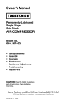
Owner's Manual
i CRHFTSMRN'i
Permanently
2-Stage
Twin V
Portable
Lubricated
AIR COMPRESSOR
Model No.
919.167783
•
Safety Guidelines
•
Assembly
•
Operation
•
Maintenance
•
Service
•
Troubleshooting
•
Repair
CAUTION:
and Adjustments
Parts
Read the Safety Guidelines
and All Instructions
Operating.
Carefully Before
Sears, Roebuck and Co., Hoffman Estates, IL 60179 U.S.A.
Visit our Craftsman website: www.sears.com/craftsman
D30087
Rev0
9/26/03
WARRANTY ................................................
SPECIFICATION CHART .....................................
SAFETY GUIDELINES ......................................
2
3
3-8
GLOSSARY ................................................
ACCESSORIES
.............................................
DUTY CYCLE ..............................................
9
9
9
ASSEMBLY ...............................................
INSTALLATION ..........................................
OPERATION ............................................
MAINTENANCE
.........................................
SERVICE AND ADJUSTMENTS
............................
10
11-12
13-15
16-17
18-19
STORAGE ................................................
TROUBLESHOOTING
GUIDE ..............................
REPAIR PARTS .........................................
ESPAI_IOL ..............................................
20
21-23
24-27
28-49
NOTES/NOTAS
............................................
REPAIR PROTECTION AGREEMENTS .........................
HOW TO ORDER REPAIR PARTS ......................
50
51
back cover
ltl__1;| ;[_I_ hi"
FULL ONE YEAR WARRANTY AIR COMPRESSOR
If this CRAFTSMAN Air Compressor fails due to a defect in material or
workmanship within one year from the date of purchase, Sears will at its
option repair or replace it free of charge. Contact your nearest Sears Service
Center (1-800-4-MY-HOME ®)to arrange for repair, or return the Air
Compressor to the place of purchase for replacement.
If this Air Compressor is used for commercial or rental purposes, this warrant
applies for only ninety days from the date of purchase.
This warranty gives you specific legal rights and you may have other rights
which vary from state to state.
Sears, Roebuck and Co., Dept. 817WA, Hoffman Estates, IL 60179
D30087
2* ENG
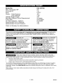
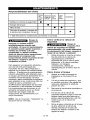
Model No.
Max. Developed HP
Running HP
Bore
Stroke
High Pressure
Low Pressure
Voltage-Single Phase
Minimum Branch Circuit Requirement
Fuse Type
Air Tank Capacity - Gallons
Approximate Cut-in Pressure
Approximate Cut-out Pressure
919-167783
3.5
1.6
2.375"
.54"
1.45"
120
15 amps
Time Delay
25 ASME
145
175
Refer to Glossary for abbreviations.
[-.'Y.,I
_1_ I_'d[€-lJ]Im]=1IqI_I ::_'_.,I m]::1_11
_1i II[e_]_._
This manual contains information that is important for you to know and understand. This information
relates to protecting YOUR SAFETY and PREVENTING EQUIPMENT PROBLEMS. To help you
recognize this information_ we use the symbols below. Please read the manual and pay attention to
these sections.
_lndicates
situation
an
imminently hazardous
if not avoided, will
which,
result in death
or serious
_lndicates
hazardous
which,
if not avoided,
death
or serious
_l_'_'_lndicates
hazardous
which, if not avoided, _
result in
minor or moderate injury.
injury.
a potentially
situation
could
a potentially
situation
_1_"_
Used without the
safety alert symbol
indicates a potentially hazardous
situation which, if not avoided, may
result in oroDertv damaae.
result in
injury.
IhSl_o]-']nq.,1+hd
b"Y.'_l_"_'d _[IP,[.._l_o]nj[o _]P,[..+
Some dust created by power sanding, sawing, grinding, drilling, and other
construction activities contains chemicals known (to the State of California) to
cause cancer, birth defects or other reproductive harm. Some example of these chemicals are:
lead from leed-based
crystalline
paints
silica from bricks and cement
arsenic and chromium
and other masonry products
from chemically*treated
lumber
Your risk from these exposures varies, depending on how often you do this type of work. To reduce
your exposure to these chemicals: work in a well ventilated area, and work with approved safety
equipment, a_ways wear MSHA/NIOSH
approved, properly fitting face mask or respirator when using
such tools.
When using air tools, basic safety precautions
personal injury.
should
3-ENG
always be followed
to reduce the risk of of
D30087
I I_ I_o] ;111P'.'q
+IInl[,.'9'.,_
_1_ &'i __JL_[,._)III,_]LI_+']IIT[_o
_+]L_,[,._
Save these instructions
Improper operation or maintenance of this product could result in serious injury and
property damage. Read and understand all warnings and operation instructions before
using this equipment,
,l;1"l'J "-In
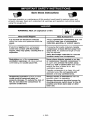
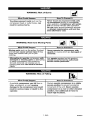
WARNING: Risk of explosion or fire
What Could Happen
How To Prevent It
It is normal for electrical contacts
within the motor and pressure switch to
spark,
Always operate the compressor in a well
ventilated area free of combustible
materials, gasoline, or solvent vapors.
If electrical sparks from compressor
come into contact with flammable
vapors, they may ignite, causing fire or
explosion,
If spraying flammable materials, locate
compressor at least 20 feet away from
spray area. An additional length of hose
may be required,
Store flammable materials in a secure
location away from compressor.
Restricting any of the compressor
ventilation openings will cause serious
overheating and could cause fire,
Never place objects against or on top
of compressor. Operate compressor in
an open area at least 12 inches away
from any wall or obstruction that would
restrict the flow of fresh air to the
ventilation openings.
Operate compressor in a clean, dry wall
ventilated area. Do not operate unit
indoors or in any confined area.
Unattended operation of this product
could result in personal injury or
property damage. To reduce the risk of
fire, do not allow the compressor to
operate unattended.
Always remain in attendance with the
)roduct when it is operating.
Always disconnect electrical power by
moving pressure switch lever to the off
}osition and drain tank daily or after
each use.
D30087
4* ENG
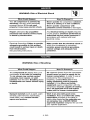
WARNING:
Risk of Bursting
Air Tank: The following conditions could lead to a weakening of the tank, and result
in a violent tank explosion and could cause property damage or serious injury,
What Could Haopen
How To Prevent It
Failure to properly drain condensed
water from tank, causing rust and
thinning of the steel tank.
Modifications
the tank.
or attempted
repairs
Unauthorized
modifications
to the
Drain tank daily or after each use. If
tank develops a leak, replace it
immediately with a new tank or replace
the entire compressor.
to
Never drill into, weld, or make any
modifications to the tank or its
attachments.
unloader valve, safety valve, or any
other components which control tank
pressure.
Excessive vibration can weaken the
air tank and cause rupture or
explosion
ATTACHMENTS
& ACCESSORIES:
Exceeding the pressure rating of air
tools, spray guns, air operated
accessories, tires, and other inflatables
can cause them to explode or fly apart,
and could result in serious injury.
WARNING:
The tank is designed to withstand specific
operating pressures. Never make
adjustments or parts substitutions to
alter the factory set operating
pressures=
For essential control of air pressure, you
must install a pressure regulator and
pressure gauge to the air outlet (if not
equipped) of your compressor. Follow the
equipment manufacturers
recommendation
and never exceed the
maximum allowable pressure rating of
attachments. Never use compressor to
inflate small low pressure objects such
as children's toys, footballs,
basketballs, etc.
Risk from Flying Objects
What Could Happen
The compressed air stream can cause
soft tissue damage to exposed skin
and can propel dirt, chips, loose
particles, and small objects at high
speed, resulting in property damage or
personal injury.
How To Prevent It
Always wear ANSI Z87.1 approved
safety
glasses with side shields when using the
compressor.
Never point any nozzle or sprayer
toward any part of the body or at other
people or animals.
Always turn the compressor off and
bleed pressure from the air hose and tank
before attempting maintenance, attaching
to0_s
5* ENG
Oi" accessories,
D30087
WARNING: Risk of Electrical Shock
What Could Happen
How To Prevent It
Your air compressor is powered by
electricity. Like any other electrically
powered device, If it is not used
properly it may cause electdc shock.
Never operate the compressor outdoors
when it is raining or in wet conditions.
Never operate compressor with
protective covers removed or damaged.
Repairs attempted by unqualified
personnel can result in serious injury
or death by electrocution.
Any electrical wiring or repairs required
on this product should be performed by
authorized service center personnel in
accordance with national and local
electrical codes.
Electrical Grounding: Failure to provide
adequate grounding to this product
could result in serious injury or death
from electrocution.
Make certain that the electrical circuit to
which the compressor is connected
provides proper electrical grounding,
correct voltage and adequate fuse
protection.
See grounding instructions.
,1:1"1'.111=
WARNING:
Risk of Breathing
What Could Happen
How To Prevent It
The compressed air directly from your
compressor is not safe for breathing.
The air stream may contain carbon
monoxide, toxic vapors, or solid
particles from the tank. Breathing these
contaminants can cause serious injury
or death.
Air obtained directly from the compressor
should never be used to supply air for
human consumption. In order to use air
produced by this compressor for
breathing, suitable filters and in-line
safety equipment must be properly
installed. In-line filters and safety
equipment used in conjunction with the
compressor must be capable of treating
air to all applicable local and federal
codes prior to human consumption.
Sprayed materials such as paint, paint
solvents, paint remover, insecticides,
weed killers, may contain harmful
vapors and poisons.
Work in an area with good cross
ventilation. Read and follow the safety
instructions
provided on the label or
safety data sheets for the materials you
ere spraying. Use a NtOSH/MSHA
approved respirator designed for use with
your specific application.
D30087
6 * ENG
WARNING: Risk of Burns
How To Prevent It
What Could Happen
Never touch any exposed metal parts
on compressor during or immediately
after operation. Compressor will remain
hot for several minutes after operation.
Do not reach around protective shrouds
or attempt maintenance until unit has
been allowed to cool.
Touching exposed metal such as the
compressor head or outlet tubes, can
result in serious burns.
,19",#.,_:
I=
WARNING:
Risk from
Moving
Parts
What Could Happen
How To Prevent It
Moving parts such as the pulley, flywheel,
and belt can cause serious injury if they
come into contact with you or your
clothing.
Never operate the compressor with
guards or covers which are damaged or
removed.
Attempting to operate compressor with
damaged or missing parts or attempting
to repair compressor with protective
shrouds removed can expose you to
moving parts and can result in serious
injury.
Any repairs required on this product
should be performed by authorized
service center personnel.
,19",#.,I:I =
WARNING:
Risk of Falling
What Could Happen
A portable compressor can fall from a
table, workbench, or roof causing
damage to the compressor and could
result in serious injury or death to the
operator,
How To Prevent It
Always operate compressor in a stable
secure position to prevent accidental
movement of the unit. Never operate
compressor on a roof or other elevated
position. Use additional air hose to
reach high locations.
7÷ ENG
D30087
WARNING:
Risk
Transporting
of Serious
Injury
or Property
Damage
When
Compressor
(Fire, Inhalation, Damage to VehicleSurfaces)
What Could Happen
How To Prevent It
Oil can leak or spill and could result in
fire or breathing hazard; serious injury or
death can result, oil leaks will damage
carpet, paint or other surfaces in
vehicles or trailers,
WARNING:
Risk of Unsafe
Always place COMPRESSOR on a
protective mat when transporting to
protect against damage to vehicle from
leaks. Remove COMPRESSOR from
vehicle immediately upon arrival at your
destination.
Operation
What Could Happen
How To Prevent It
Unsafe operation of your air compressor
could lead to serious injury or death to
you or others.
SAVE THESE
D30087
_1=
Review and understand all instructions
and warnings in this manual.
Become familiar with the operation and
controls of the air compressor.
Keep operating area clear of all persons,
pets, and obstacles.
Keep children away from the air
compressor at all times.
Do not operate the product when
fatigued or under the influence of
alcohol or drugs. Stay alert at all times.
Never defeat the safety features of this
product.
Equip area of operation with a fire
extinguisher.
DO not operate machine with missing,
broken, or unauthorized parts.
INSTRUCTIONS
8* ENG
Become familiar with these terms
before operating the unit.
CFM: Cubic feet per minute.
SCFM: Standard cubic feet per
minute; a unit of measure of air
delivery.
PSlG: Pounds per square inch
gauge; a unit of measure of pressure.
Code Certification:
Products that
bear one or more of the following
marks: UL, CUL, ETL, CETL, have
been evaluated by OSHA certified
independent safety laboratories and
meet the applicable Underwriters
Laboratories Standards for Safety.
Cut-In Pressure: While the motor is
off, air tank pressure drops as you
continue to use your accessory.
When the tank pressure drops to a
certain low level the motor will restart
automatically.
The low pressure at
which the motor automatically
restarts is called "cut-in" pressure.
Cut-Out Pressure: When an air
compressor is turned on and begins
to run, air pressure in the air tank
begins to build. It builds to a certain
high pressure before the motor
automatically shuts off, protecting
your air tank from pressure higher
than its capacity. The high pressure
at which the motor shuts off is called
"cut-out" pressure.
Branch Circuit: Circuit carrying
electricity from electrical panel to
outlet.
This unit is capable of powering the following Accessories. The accessories are
available through the current Power and Hand Tool Catalog or full-line Sears
stores.
Accessories
= In Line Filter
• Tire Air Chuck
•
•
•
Refer to the selection chart located
on the unit to select the tools this unit
is capable of powering.
•
Quick Connector Sets (various
sizes)
Air Pressure Regulators
ml_Tujnj_
[e,_
This air compressor pump is capable
of running continuously. However, to
prolong the life of your air
compressor, it is recommended that a
50%-75% average duty cycle be
Oil Fog Lubricators
Air Hose: 1/4", 3/8" or 1/2" I.D. in
various lengths
q=1
maintained; that is, the air
compressor pump should not run
more than 30-45 minutes in any given
hour.
9- ENG
D30087
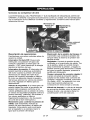
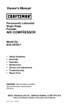
Contents
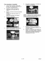
Assemble Wheels
of Carton
1 - Air Compressor
2-
It will be necessary
to brace or support
one side of the air compressor
when installing the wheels because
the compressor will have a
tendency to tip.
1. Attach wheels with shoulder
bolts and nuts as shown.
Wheels
2 - Shoulder Bolts, 3/8-16
2-
Hex Nuts, 3/8-16
2-
Rubber Bumpers
2 - Screws, 1/4-20
Tools Required
x .75"
for Assembly
[_
1 - 9/16" socket or open end wrench
r_
Rubber
___eet
1 - 1/2" socket or open end wrench
Unpacking
1.
2.
Remove all packaging leaving
the air compressor on the pallet.
Nut
Remove and discard the (4)
screws holding the air
compressor to the pallet.
_/_.
Shoulder
Bolt
2.
Tighten securely. NOTE: The air
compressor will sit level if the
wheels are properly installed.
I_'_'j_
It may be
necessary to brace
or support one side of the air
compressor when removing the
pallet because the air compressor
will have a tendency to tip.
3.
The wheels and
handle do not
provide adequate clearance,
stability or support for pulling the
unit up and down stairs or steps.
The unit must be lifted, or pushed
up a ramp.
Assemble Rubber Feet
1.
Attach rubber feet with the
screws provided as shown in
previous figure.
2.
Tighten securely.
Carefully remove the air
compressor from the pallet.
D30087
10_ ENG
I I_[-.'_1
f;_II Ir;'ul[o_J
HOW TO SET UP YOUR
IMPORTANT: The outlet being used
must be installed and grounded in
accordance with all local codes and
ordinances.
UNIT
Location of the Air Compressor
Locate the air compressor in a clean,
dry and well ventilated area. The air
compressor should be located at
least 12" away from the wall or other
obstructions that will interfere with
the flow of air. The air compressor
pump and shroud are designed to
allow for proper cooling. The
ventilation openings on the
compressor are necessary to
maintain proper operating
temperature. Do not place rags or
other containers on or near these
openings.The air filter must be kept
clear of obstructions which could
reduce air flow to the air compressor.
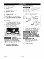
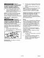
GROUNDING
Make sure the outlet being used
has the same configuration as
the grounded plug. DO NOT
USE AN ADAPTER. See
illustration.
2.
II_lu_j
_Groended
_
_Outlets
Grou_d_ing Pin
INSTRUCTIONS
of Electrical
Shock. In the event
of a short circuit, grounding
reduces the risk of shock by
providing an escape wire for the
electric current. This air
compressor must be properly
grounded.
The portable air compressor is
equipped with a cord having a
grounding wire with an appropriate
grounding plug (see following
illustrations). The plug must be used
with an outlet that has been installed
and grounded in accordance with all
local codes and ordinances.
3.
Inspect the plug and cord before
each use. Do not use if there are
signs of damage.
4.
If these grounding instructions
are not completely understood,
or if in doubt as to whether the
compressor is properly
grounded, have the installation
checked by a qualified
electrician.
_Risk
1.
_"_
Risk of Electrical
Shock. Improper
grounding can result in electrical
shock.
Do not modify the plug provided. If
it does not fit the available outlet, a
correct outlet should be installed
by a qualified electrician.
Repairs to the cord set or plug
MUST be made by a qualified
electrician.
The cord set and plug with this
unit contains a grounding pin.
This plug MUST be used with a
grounded outlet.
11_ ENG
D30087
Extension Cords
Voltage
Using extension cords is not
recommended. The use of extension
cords will cause voltage to drop
resulting in power loss to the motor
and overheating.
Refer to the specification chart for the
voltage and minimum branch circuit
requirements.
Protection
Risk of Unsafe
Operation. Certain
air compressors can be operated
on a 15 amp circuit if the following
conditions are met,
1. Voltage supply to circuit must
comply with the National
Electrical Code.
Instead of using an extension cord,
increase the working reach of the air
hose by attaching another length of
hose to its end. Attach additional
lengths of hose as needed.
If an extension cord must be used,
be sure it is:
a 3-wire extension cord that has
a 3-blade grounding plug, and a
3-slot receptacle that will accept
the plug on the product
•
and Circuit
2.
Circuit is not used to supply any
other electrical needs.
3.
Extension cords comply with
specifications.
4.
Circuit is equipped with a 15
amp circuit breaker or 15 amp
time delay fuse. NOTE: If
compressor is connected to a
circuit protected by fuses, use
only time delay fuses. Time delay
fuses should be marked "D" in
Canada and "T" in the US.
in good condition
no longer than 50 feet
12 gauge (AWG) or larger. (Wire
size increases as gauge number
decreases. 10 AWG and 8 AWG
may also be used. DO NOT
USE 14 OR 16 AWG.)
If any of the above conditions cannot
be met, or if operation of the
compressor repeatedly causes
interruption of the power, it may be
necessary to operate it from a 20
amp circuit. It is not necessary to
change the cord set.
D30087
12- ENG
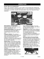
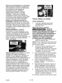
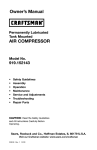
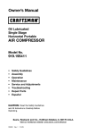
Know
Your Air Compressor
READ THIS OWNER'S MANUAL AND SAFETY RULES BEFORE OPERATING
YOUR UNIT. Compare the illustrations with your unit to familiarize yourself with
the location of various controls and adjustments. Save this manual for future
reference.
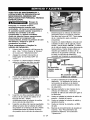
Universal
QuickConnect
Body
Regulator
Safety Valve
Description
of Operation
Become familiar with these controls
before operating the unit.
On/Auto/Off Switch: Turn this switch
ON to provide automatic power to
the pressure switch and OFF to
remove power at the end of each
use.
Pressure Switch: The pressure
switch automatically starts the motor
when the air tank pressure drops
below the factory set "cut-in"
pressure. It stops the motor when the
air tank pressure reaches the factory
set "cut-out" pressure.
Safety Valve: If the pressure switch
does not shut off the air compressor
at its "cut-out" pressure setting, the
safety valve will protect against high
pressure by "popping out" at its
factory set pressure (slightly higher
than the pressure switch "cut-out"
setting).
Outlet Pressure Gauge: The outlet
pressure gauge indicates the air
pressure available at the outlet side
of the regulator. This pressure is
controlled by the regulator and is
always less than or equal to the tank
pressure.
Tank Pressure Gauge: The tank
pressure gauge indicates the reserve
air pressure in the tank.
Regulator: Controls the air pressure
shown on the outlet pressure gauge.
Pull the knob out and turn clockwise
to increase pressure and
counterclockwise
to decrease
pressure. When the desired pressure
is reached push knob in to lock in
place.
Universal Quick-Connect Body:
The universal quick-connect body
accepts the three most popular styles
of quick-connect plugs: Industrial,
automotive (Tru-flate), and ARC. One
hand push-to-connect
operation
makes connections simple and easy.
Drain Valve: The drain valve is
located at the base of the air tank
and is used to drain condensation at
the end of each use.
13_ ENG
D30087
Cooling System (not shown): This
compressor contains an advanced
design cooling system. At the heart
of this cooling system is an
engineered fan. It is perfectly normal
for this fan to blow air through the
vent holes in large amounts. You
know that the cooling system is
working when air is being expelled.
Air Compressor
Pump (net shown):
Compresses air into the air tank.
Working air is not available until the
compressor has raised the air tank
pressure above that required at the
air outlet.
Check Valve: When the air
compressor is operating, the check
valve is "open", allowing compressed
air to enter the air tank. When the air
compressor reaches "cut-out"
pressure, the check valve "closes",
allowing air pressure to remain inside
the air tank.
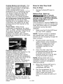
How to Use Your Unit
How to Stop:
1.
Set the On/Auto/Off lever to
"OFF".
Before
First
Start-up
Risk of Unsafe
Operation. Serious
damage may result if the following
break-in instructions are not
closely followed,
This procedure is required before the
air compressor is put into service and
when the check valve or a complete
compressor pump has been
replaced.
1. Make sure the On/Auto/Off lever
is in the "OFF" position.
NOTE: If quick connect is installed,
pull coupler back until it clicks to
prevent air from escaping through the
quick connect.
2.
Plug the power cord into the
correct branch circuit receptacle.
(Refer to Voltage and Circuit
Protection paragraph in the
Installation section of this
manual.)
3. Open the drain valve fully
Pressure Release Valve: The
(counterclockwise) to permit air
pressure release valve located on the
to escape and prevent air
side of the pressure switch, is
pressure build up in the air tank
designed to automatically release
during the break-in period.
compressed air from the compressor
head and the outlet tube when the air
NOTE: Always drain tank on a
compressor reaches "cut-out"
washable surface or in a suitable
pressure or is shut off. The pressure
container to prevent damaging or
release valve allows the motor to
staining surfaces.
restar_ freely.
When the
4.
Move the On/Auto/Off lever to
motor stops
"ON/AUTO" position. The
running, air
compressor will start.
will be heard
5.
Run the compressor for 15
escaping
minutes. Make sure the drain
from this
valve for a
valve is open and there is
few seconds.
minimal air pressure build-up in
No air should
tank.
be heard leaking when the motor is
running or after the unit reaches "cutout" pressure.
D30087
14_ENG
6. After15minutes,
closethedrain
valve(clockwise).
Theairreceiver
willfillto"cut-out"
pressure
and
themotorwill stop.
Thecompressor
is nowreadyforuse.
Before
1.
Each Start-Up:
Place On/Auto/Off lever to
"OFF" and close air regulator.
Risk of Bursting.
Too much air
pressure causes a hazardous risk
of bursting, Check the
manufacturer's maximum pressure
rating for air tools and accessories,
The regulator outlet pressure must
never exceed the maximum
pressure rating.
How to Start:
2.
Pull regulator knob out, turn
counterclockwise
until it stops.
Push knob in to lock in place.
3.
Attach hose and accessories.
NOTE: The hose or accessory
will require a quick connect plug
if the air outlet is equipped with a
quick connect socket.
1.
Turn the On/Auto/Off lever to
"AUTO" and allow tank pressure
to build. Motor will stop when
tank pressure reaches "cut-out"
pressure.
2.
Pull the regulator knob out and
turn clockwise to increase
pressure. When the desired
pressure is reached push knob in
to lock in place.
The compressor
15_ ENG
is ready for use.
D30087
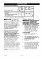
Customer
Responsibilities
Before Daily or
after
Every
_ach each
40
L_se
use
hours
Check Safety Valve
Every
100
_ours
Yearly
•
Drain Tank
•
Air Filter
Air compressor pump intake
and exhaust valves
•1
9
•
1- more frequent in dusty or humid conditions
Risk of Unsafe
Operation. Unit
cycles automatically when power is
on. When servicing, you may be
exposed to voltage sources,
compressed air, or moving parts.
Before servicing unit unplug or
disconnect electrical supply to the
air compressor, bleed tank of
pressure, and allow the air
compressor to cool.
To ensure efficient operation and
longer life of the air compressor
outfit, a routine maintenance
schedule should be prepared and
followed. The above routine
maintenance schedule is geared to
an outfit in a normal working
environment operating on a daily
basis. If necessary, the schedule
should be modified to suit the
conditions under which your
compressor is used. The
modifications will depend upon the
hours of operation and the working
environment. Compressor outfits in
an extremely dirty and/or hostile
environment will require a greater
frequency of all maintenance checks.
NOTE: See "Operation"
the location of controls.
D30087
To Check
Safety
Valve
Risk of Bursting. If
the safety valve
does not work properly, overpressurization may occur, causing
air tank rupture or an explosion.
1. Before starting compressor, pull
the ring on the safety valve to
make sure that the safety valve
operates freely. If the valve is
stuck or does not operate
smoothly, it must be replaced
with the same type of valve.
To Drain Tank
1.
Set the On/Auto/Off lever to
"OFF" and unplug unit.
2.
Pull the regulator knob out and
turn counter-clockwise
to set the
outlet pressure to zero.
3.
Remove the air tool or
accessory.
4.
Pull ring on safety valve allowing
air to bleed from the tank until
tank pressure is approximately
20 psi. Release safety valve ring.
5.
Drain water from air tank by
opening drain valve (counterclockwise) on bottom of tank.
section for
16_ ENG
IMPORTANT: Do not operate the
compressor with the air filter
removed.
I_
Risk of Bursting.
Water will
condense in the air tank. If not
drained, water will corrode and
weaken the air tank causing a risk
of air tank rupture.
6.
After the water has been drained,
close the drain valve (clockwise).
The air compressor can now be
stored.
NOTE: If drain valve is plugged,
release all air pressure. The valve
can then be removed, cleaned, the
reinstalled.
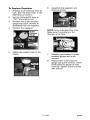
Air Filter Inspection
Replacement
A dirty air filter will not allow the
compressor to operate at full
capacity. Keep the air filter clean at
all times.
Remove the air filter cover.
Remove the air filter and make
sure it is clean.
4.
Replace air filter and air filter
cover.
NOTE: If the air filter is extremely
dirty it will need to be replaced. Refer
to the "Repair Parts" for the correct
part number.
Intake
Once a year have a Trained Service
Technician check the air compressor
pump intake and exhaust valves.
Risk of Burns.
Compressor head
and cylinder sleeve are very hot.
Do not touch. Allow compressor to
cool prior to servicing
2.
If dirty, rinse air filter with warm
water and squeeze dry.
Air Compressor
Pump
and Exhaust Valves
and
1.
3.
1
Motor
The motor has an automatic reset
thermal overload protector. If the
motor overheats for any reason, the
overload protector will shut off the
motor. The motor must be allowed to
cool down before restarting. The
compressor will automatically restart
after the motor cools.
If the overload protector shuts the
motor off frequently, check for a
possible voltage problem. Low
voltage can also be suspected when:
The motor does not get up to full
power or speed.
Air Filter
ir Filter
J/
Fuses blow out when starting
the motor; lights dim and remain
2.1" dim when motor is started and is
running.
17_ ENG
D30087
ALL MAINTENANCE AND REPAIR
OPERATIONS NOT LISTED MUST
BE PERFORMED BY A TRAINED
SERVICE TECHNICIAN.
Outlet Tube
Risk of Unsafe
Operation. Unit
cycles automatically when power is
on. When servicing, you may be
exposed to voltage sources,
compressed air, or moving parts.
Before servicing unit unplug or
disconnect electrical supply to the
air compressor, bleed tank of
pressure, and allow the air
compressor to cool.
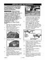
TO Replace or Clean Check
Valve
1.
2.
3.
7.
Unscrew the check valve (turn
counterclockwise)
using a 7/8"
open end wrench. Note the
orientation for reassembly.
8.
Using a screwdriver, carefully
push the valve disc up and
down. NOTE: The valve disc
should move freely up and down
on a spring which holds the valve
disc in the closed position; if not
the check valve needs to be
cleaned or replaced.
Release all air pressure from air
tank. See "To Drain Tank" in the
Maintenance section.
Set the On/Auto/Off lever to
"OFF" and unplug unit.
Using a phillips screwdriver,
remove the air filter cover.
open
position
nothing is
visible,
4.
tn closed position
disc is visible.
Remove the rear shrouds using
T-20 torx wrench.
9.
5.
Using an adjustable wrench,
loosen outlet tube nut at air tank.
Carefully move outlet tube away
from check valve.
6.
Using an adjustable wrench
loosen pressure relief tube nut at
air tank. Carefully move pressure
relief tube away from check
valve.
D30087
Clean or replace the check valve.
A solvent, such as paint or
varnish remover can be used to
clean the check valve.
10. Apply sealant to the check valve
threads. Reinstall the check valve
(turn clockwise).
11. Replace the pressure release
tube. Tighten nut.
12. Replace the outlet tube and
tighten nut.
13. Replace the shroud and air filter.
14. Perform the Break-in Procedure.
See "Break-in Procedure" in the
Operation section.
18- ENG
To Replace Regulator
1. Release all air pressure from air
tank. See "To Drain Tank" in the
Maintenance section.
2. Set the On/Auto/Off lever to
"OFF" and unplug unit.
3. Remove the outlet pressure
gauge and quick connect (if
equipped) from the regulator.
4. Remove the regulator.
6.
Assemble the regulator and
orient as shown.
NOTE: Arrow indicates flow of air.
Make sure it is pointing in the
direction of air flow.
Regulator
5.
Apply pipe sealant tape to the
nipple.
7.
Reapply pipe sealant to outlet
pressure gauge and quick
connect.
8.
Reassemble outlet pressure
gauge and quick connect. Orient
outlet pressure gauge to read
correctly. Tighten quick connect
with wrench.
19_ ENG
D30087
Before you store the air compressor,
make sure you do the following:
Risk of Bursting.
Water will
condense in the air tank. If not
drained, water will corrode and
weaken the air tank causing a risk
of air tank rupture.
1.
Review the "Maintenance"
section on the preceding pages
and perform scheduled
maintenance as necessary.
2.
Set the On/Auto/Off lever to
"OFF" and unplug unit.
7.
3.
Turn the regulator
counterclockwise
and set the
outlet pressure to zero.
4.
Remove the air tool or
NOTE: If drain valve is plugged,
release all air pressure. The valve
can then be removed, cleaned, then
reinstalled.
accessory.
5.
Pull ring on safety valve allowing
air to bleed from the tank until
tank pressure is approximately
20 psi. Release safety valve ring.
6.
Drain water from air tank by
opening drain valve on bottom of
tank.
D30087
After the water has been drained
close the drain or drain valve.
8.
Protect the electrical cord and air
hose from damage (such as
being stepped on or run over).
Wind them loosely around the
compressor handle.
9.
Store the air compressor
clean and dry location.
20_ ENG
in a
d:{ollJ :] il ::F,."]
-"[oIo]l III _[I
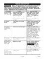
Risk of Unsafe Operation. Unit cycles automatically when
power is on. When servicing, you may be exposed to
voltage sources, compressed air, or moving parts. Before servicing unit
unplug or disconnect electrical supply to the air compressor, bleed tank of
pressure, and allow the air compressor to cool.
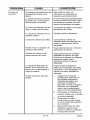
PROBLEM
CAUSE
CORRECTION
Pressure switch does not
shut off motor when
compressor reaches
"cut-out" pressure.
Move On/Auto/Off lever to
the "OFF" position, if the
outfit does not shut off
contact a Trained Service
Technician.
Pressure switch "cut-out"
too high.
Contact a Trained Service
Technician.
Air leaks at
fittings.
Tube fittings are not tight
enough.
Air leaks at or
inside check
valve.
Check valve seat damaged.
Tighten fittings where air can
be heard escaping. Check
fittings with soapy water
solution. Do Not
Overti_hten.
A defective check valve
results in a constant air leak
at the pressure release valve
when there is pressure in the
tank and the compressor is
shut off. Replace check
valve. Refer to the "To
Replace or Clean Check
Valve" in the "Service and
Adjustment" section.
Air leaks at
pressure switch
release valve.
Defective pressure switch
release valve.
Contact a Trained Service
Technician.
Air leaks in air
tank or at air
tank welds.
Defective air tank.
Air tank must be replaced.
Do not repair the leak.
Air leaks
between head
Leaking seal.
Excessive tank
pressure - safet
valve pops off.
Risk of
Bursting.
Do not drill into, weld or
otherwise modify air tank
or it will weaken. The tank
can rupture or explode.
Contact a Trained Service
Technician.
and valve plate.
21_ENG
D30087
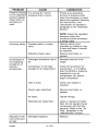
PROBLEM
Pressure reading
on the regulated
pressure gauge
drops when an
accessory is
used.
Knocking
Noise.
CAUSE
CORRECTION
It is normal for "some"
)ressure drop to occur.
Possible defect in safety
valve.
Defective check valve.
Compressor is
not supplying
enough air to
operate
accessories.
Regulator knob
has continuous
air leak.
D30087
If there is an excessive
amount of pressure drop
when the accessory is used,
adjust the regulator following
the instructions in the
"Description of Operation"
paragraph in the "Operation
Section."
NOTE: Adjust the regulated
)ressure under flow
conditions (while accessory
is being used).
Operate safety valve
manually by pulling on ring.
If valve still leaks, it should
be replaced.
Remove and clean, or
replace.
Prolonged excessive use of
air.
Decrease amount of air
usage.
Compressor is not large
enough for air requirement.
Check the accessory air
requirement. If it is higher
than the SCFM or pressure
supplied by your air
compressor, you need a
larger compressor.
Hole in hose.
Check and replace if
required.
Check valve restricted.
Remove and clean, or
replace.
Air leaks.
Tighten fittings.
Restricted air intake filter.
Clean or replace air intake
filter. Do not operate the air
compressor with the filter
removed. Refer to the "Air
Filter" paragraph in the
"Maintenance" section.
Damaged regulator.
Replace.
22_ ENG
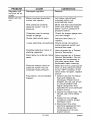
PROBLEM
CAUSE
CORRECTION
Regulator will
not shut off air
outlet.
Damaged regulator.
Replace.
Motor will not
run.
Motor overload protection
switch has tripped.
Let motor cool off and
overload switch will
automatically reset.
Tank pressure exceeds
pressure switch "cut-in"
Motor will start automatically
when tank pressure drops
below "cut-in" pressure of
)ressure switch.
pressure.
Extension cord is wrong
length or gauge.
Check for proper gauge wire
and cord length.
Check valve stuck open.
Loose electrical connections.
Remove and clean, or
replace.
Check wiring connection
inside pressure switch and
terminal box area.
Possible defective motor or
starting capacitor.
Have checked by a Trained
Service Technician.
Paint spray on internal motor
3arts.
Have checked by a Trained
Service Technician. Do not
operate the compressor in
the paint spray area. See
flammable vapor warning.
Bleed the line by pushing the
lever on the pressure switch
to the "OFF" position; if the
valve does not open, replace
switch.
1. Check fuse box for blown
fuse and replace as
necessary. Reset circuit
breaker. Do not use a fuse
or circuit breaker with
higher rating than that
specified for your particular
branch circuit.
2. Check for proper fuse. You
should use a time delay
fuse.
3. Check for low voltage
conditions and/or proper
extension cord.
4. Disconnect the other
electrical appliances from
circuit or operate the
compressor on its own
branch circuit.
Pressure release valve on
pressure switch has not
unloaded head pressure.
Fuse blown, circuit breaker
tripped.
23_ ENG
D30087
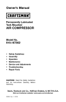
._I-'I_o]_V_l
*_-'!
_o]
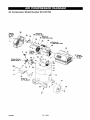
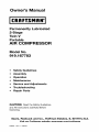
Air Compressor
To L_
tolr_25
in,4bs,
-IIm]¥,__€_,__
_v
Model Number 919.167783
36
Torque to
3 6-10 _n.-Ibs.
Torque to
_2 100-120 in,4bs.
3O
29Torque to
,
100-120 In.-Ibs.
28
J
26
41
25
27TO_lUe
to 15-25
_.-Ibs.
10
18
!
31
D30087
24_ ENG
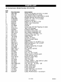
Air Compressor
Key
No.
1
2
3
4
5
6
8
9
10
11
12
13
14
15
16
17
18
19
20
21
22
23
25
26
27
28
29
30
31
32
33
34
35
36
37
38
39
40
41
43
44
45
46
60
Model Number 919.167783
PaN Number
SSF-990
ACG-18
D21929
SST-108
91895680
Z-D26613
D30198
D26615
D23067
AC-0609
D21172
Z-D21872
D20584
SSP-7811
SSP-7813
AC-0631
D23574
TIA-4200
AC-0774
D20675
D27253
SS-2071
SSP-6021
ACG-61-2
ACG-408
AC-0803
SSP-7821-1
SSG-3105
D23000
AC-0780
SSF-554
AC-0783
919-16433
ACG-14
AC-0558
AC-0781
AC-0802
SSF-8080-ZN
LA-3105
LA-3027
Z-D27352
LA-3021
LA-3108
D30079
Descr_tion
Screw 1/4-20UNC-2ATHD
(2 used)
Cup Saddle Mount (2 used)
Gauge Back Mount 300 PSIG (2 used)
Rubber Bumper 60 Durometer
Screw 1/4 - 20 x .75 (2 used)
Pressure Switch
Nipple 1/4-18 NPTx 2.50
Power Cord Assembly
Wheel 10"
Handle
Screw Hex HD Self Tapping (4 used)
Tank 20G Vertical
Pressure Relief Tube
Nut Sleeve Assembly 1/4"
Nut Sleeve Assembly 3/8"
Check Valve 7/8 HEX x 1/4
Shoulder Bolt 3/8 - 16
Safety Valve
Isolator (3 used)
Quick Connect Body
Regulator
Nipple Close 1/4-18 NPT x1.5
Busning Reducer 1/8-1/4 NPT
Shroud, Rear
Fastener Assembly (3 used)
Outlet Tube
Nut Tubing 3/8"0D
O-Ring
Drain Valve
Nut, 3/4-16 (2 used)
Screw 10-14 x 2.5 (2 used)
Intake Muffler Cover
Element Intake Filter
Shroud, Front
Grip .875 DIA
O-Ring .3621D x .103 width (2 used)
Interconnecting Tube
Hex Nut 3/8 - 16 UNC - 2B
Label, Craftsman
Label, Drain Tank
Pump Assembly
Label, Warning - not shown
Label, Hot Surface
Label, Performance - not shown
25_ ENG
D30087
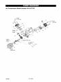
Air Compressor
Model Number 919.167783
12
9 Torque
7-10 ft,-Ibs.
16
14
J
13
8
_3
Torque
25-35 2
ft.qbs,
Torque25-35 ft,-Ibs.
_7Torque
75-90 in.qbs,
D30087
26_ ENG
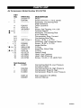
Air Compressor
KEY
NO.
1
2
3
•
•
*•
*•
4
6
7
#+8
9
9-2
9-3
9-4
+10
+ 11
12
#+ 13
14
#+ 15
+ 16
17
18
19
Model Number 919.167783
PART NO.
Z-D26717
D24596
D24597
ACG-22
39124607
SSF-3158-1
D20605
ACG-11
SSG-8156
Z-D29777
ACG-45
AC-0779
AC-0805
AC-0784
AC-0798
Not Illustated
•
K-0651
+
#
DESCRIPTION
Motor
Screw 5/16-24 x 1.75 (2 used))
Assembly, Connecting Rod
(High Pressure)
Outer Eccentric
Fan
Screw, Self Tapping 1/4 x 5/8
Cylinder Sleeve
Assembly, Connecting Rod
(Low Pressure)
Compression Ring, Formed
Connecting Rod Cap
Screw, 10-24 x .75 T25
Assembly, High Pressure Piston
Screw, 10-32 x .75 T25
Intake Muffler
O-Ring
Assembly, Valve Plate
O-Ring
Gasket Head
Head, Low Pressure
Head, High Pressure
Screw, 1/4-20 x 1.25 HHW THD
D24958
K-0648
K-0650
Connecting Rod Kit-Low Pressure
Includes K-0651
Connecting Rod Kit-High Pressure
Compression Ring Kit-High
Compression Ring Kit-Low Pressure
D29142
D30087
Sta_ Capacitor Kit(WEG)
Owne_ Manual
27_ ENG
D30087
GARANT|A
CUADRO
28
DE ESPECIFICACIONES
DEFINICIONES
DE NORMAS
IMPORTANTES
INSTRUCCIONES
GLOSARIO
......................................
DE SEGURIDAD
DE SEGURIDAD
29
......................
29-34
..........................................................
ACCESORIOS
35
.......................................................
CICLO DE SERVICIO
.......................................................
INSTALACION
.....................................................
OPERACION
36
37-38
39-41
.................................................
SERVICIOS Y REGULACIONES
42-43
......................................
44-45
.......................................................
GU(A DE DIAGNOSTICO
NOTES/NOTAS
35
......................................................
MANTENIMIENTO
ALMACENAJE
35
..................................................
ENSAMBLADO
CONTRATOS
29
.............................
DE PROBLEMAS
46
.............................
47-49
.......................................................
DE PROTECCION
50
PARA REPARACIONES
LISTA DE PARTES
.................................................
COMO SOLICITAR
PIEZAS PARA REPARACION
.....................
51
24-27
....................
GARANT|A TOTAL DE UN AI_IO DEL COMPRESOR
contratapa
DE AIRE
Si este compresor de aire Craftsman fallase debido a defectos de materiales
o de fabricaci6n dentro del aSo de su fecha de compra, Sears, a su opei6n, Io
reparar& o reemplazar& sin eosto alguno. Comuniquese con el Centro de
Servicio Sears m&s cercano (1-800-4-MY-HOME) para coordinar su
reparaci6n, o devuelva el compresor de aire al lugar donde Io compr6 para
que Io cambien.
Si este compresor de aire se usase con fines comerciales o para alquiler, esta
garantia se aplica s61o durante los primeros noventa dias a partir de su fecha
de compra.
Esta garantia le otorga derechos especfficos y usted podrfa tener otros
derechos que varian de un estado a otto.
Sears, Roebuck and Co., Dept. 817WA, Hoffman Estates, IL 60179
D30087
28- SP
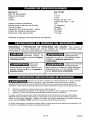
Modelo
M&x.
919.167783
3.5
1.6 HP
2.375"
Presi6n de alto -.54"
Presion de mugir - 1.45"
120
N°
HP desarrollado
Potencia
Orificio
de trabajo
Carter8
Voltaje-corriente manof&sica
Requerimientos Minimos de Circuito
Tipo de Fusible
Capacidad del Tanque de Aire - Galon
Presi6n de Arranque Aproximada
Presi6n de Corte Aproximada
Refierase al glosario para descifrar
15 Amperios
Retardo
25 ASME
145 psig
175 psig
las abreviaturas.
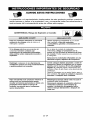
Im]=1all#l[+][o_]_J_._Im]=l_L_[']A6F_ Im]=[.'J=[dJJ ;11m].,1
m]
SEGURIDAD
Y PREVENCION
DE PROBLEMAS
DEL EQUIPO: Para ayudar al
reconocimiento
de esta informaei6n, hemos utilizado los simbolos mostrados abajo+
Sirvase leer el manual y prestar atenci6n a dichas secciones.
!ndiea una situaci6n de
mminente
riesgo,
la
cual, si no es evitada, causara la muerte
o lesiones series.
_
Indica una situaci6n
potencialmente
peligrosa, la cual, si no es evitada, podria
resultar en lesiones menores o
_
potencialmente riesgosa, que si no es
evitada, podda resultar en la
Usado sin el simbolo
de seguridad de
alerta indica una situacion potencialmente
riesgosa la que, si no es evitada, podria
lesiones
causar
set-ias,
I1_v_
I -,,[o];tl q..'t_ht =[--"]
_l]
_,[--_l[o"T_(o_
danos
en
la
DtoDiedada=
ID1_ [._='!1 ] ;,11
_7'.ID)
_
Algunos tipos de aserr[n creados pot m&quinas electricas de Iijado, aserrado,
3motado, perforado u otras actividades de la construcci6n, contienen
materiales qu_micos conocidos (en el Estado de California) como causantes de c&ncer, defectos de
nacimiento u otros d_os del aparato reproductivo. A_gunos ejemplos de dichos productos quimicos son:
•
El plomo contenido en algunas pinturas con base de pIomo
Silice cristalizado proveniente de los ladrillos, el cemento y otros productos
Ars6nioo y oromo provenientes del tr_tamiento quimico dado a la readers
de albaSilerla
Su r+esgo a dichas exposiciones variar& dependiendo de Is frecuencia con la que usted realice
diferentes tipos de trabajo. Para reducir su exposici6n a la acci6n de dichos agentes quimicos:
trabaje en zonas bien ventilada& y h&galo con equipo de seguridad aprobado, use siempre protecci6n
facial o respirador MSHA / NIOSFI aprobados cuando deba utilizar dichas herrarnientas.
AI utilizar herramientas neum&tioas tambi_n deben tomarse
de reducir la posibilidad de riesgo de lesiones personales.
29+ SP
precauciones
bAsicas de seguridad,
8 fin
D30087
GUARDE
ESTAS INSTRUCCIONES
La operaci6n o el mantenimiento
inadecuados
de este producto
serias lesiones y dafios a la propiedad.
Lea y comprenda todas
instrucciones
de funcionamiento
antes de utilizar este equipo.
podrian ocasionar
las advertencias
e
',]=lm[_ ;{_
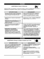
ADVERTENCIA:
qud
puede
Riesgo de Explosi6n o Incendio
occurrir
cbmo
prevenirlo
Para los contaotos el_ctricos es normal la
existencia de chispas entre el motor y el
intermptor a presi6n.
Opere siempre el compresor en un sector
bien ventilado y libre de materiales
combustibles, gasolina o emanaciones de
solvente=
Si Ias chispas el_=ctricas provenientes d_
compresor tomaran contacto con
emanaciones de materiales inflamables,
ellos podrian arder originando incendio o
explosibn.
En un &tea de rociado de materiales
infiamables, ubique al compresor por Io
menos a 6,1m (20 pies) de distancia del _rea
de rociado. Podrla requerirse una extensi6n de
la manguera,
Almacene
ubicaci6n
los materiales inflamables en una
segura, alejados del compreson
Restringir cualquiera de las aberturas de
ventilacibn causar_ un serio recalentamiento
y podrla producir un incendio.
Jamds coloque objetos apoyados o sobre el
compresor. Opere el compresor en un sector
abierto, por Io menos a 30 cm (12 pulgadas)
alejado de cualquier pared u obstrucci6n
que
restrinja el flujo de aim fresco alas aberturas de
ventilaci6n,
Opere el compresor en un sector limpio, seco, y
bien ventilado, NO opere la unidad en espacios
cerrados o cualquier drea confinada.
Dejar desatenido este producto mientras el
mismo est& en funcionamiento
puede
resultar en lesiones personales o da_os a la
propiedad= Para reducir el riesgo de
incendio, no permita que el oompresor
opere desatendido.
Mant_ngase siempre alerLa cada vez que el
_roducto este funcionando.
D30087
Desconecte siempre el suministro el_ctrico
moviendo la palanca conmutadora de
presi6n a la posici6n de apagado (off), y
drene el tanque diariamente o despu{_s de
cada uso=
30- SP
d=l![_;{q
F 3%q
ADVERTENCIA:
T_ue
de aire:
determinar
las siguientes
su explosibn
qud puede
Riesgo
de Explosibn
condiciones
violenta,
dafios
podrian,
causar
a la propiedad
occurrir
el debilitamiento
o serias
cbmo
del tanque,
prevenirlo
Drenaje inadecuado del agua condensada
en el tanque, siendo la causa del bxido que
reduce el espesor del tanque de acero,
Drene el tanque diariamente o despu_s de
cada uso. Si el tanque genera una p_rdida,
reempl&celo inmediatamente con un nuevo
tanque o reemplace el compresor completo.
Modificaciones
al tanque,
Jambs perfore, suelde, o efectOe modificacibn
alguna al tanque o sue accesorios.
o intento
de reparaciones
y
lesiones.
Modificaciones
no autorizadas
a la vblvula
de descarga, vblvula de seguridad o
cualquier otto componente
que controle la
presibn del tanque.
La vibracibn excesiva puede debilitar el
tanque de aire y causar su ruptura o
explosibn,
El tanque est& disebado para resistir presiones
operativas especfficas. Jambs efectbe ajustes
o sustituya partes que alteren las
regulaciones
de presibn originales de
fbbrica=
AGREGADOS Y ACCESORIOS
El exceso a los valores de presibn
establecidos para las hen amientas
_m_tic_,
pistoIas rociadoras, accesorios
activados por aire, cubiertas y otros obietos
inflables, puede causar su explosibn o set
arrojado& pudiendo ocasionar serias lesiones.
Para un control esencial de la presibn, debe
usted instalar un regulader y un medidor de
presibn a la salida del aire de su compresor. (Si
no estuviese equipado) Siga las recomendaciones
de los fabricantes de SU equipo y jam_s exceda
los vaIores m&ximos de presibn permifidos para
los accesorios, Jan_s use el compresor
para
inflar objetos que requieren poca o baja
presibn, tales como juguetes para los ni_os,
pelotas de ft_tbol, pelotas de basquat, etc=
d=l![d;{q
ADVERTENCIA:
Riesgo de Objetos
Arrojados pot el Aire
qud puede occurrir
cbmo prevenido
El chorro de aire comprimido puede causar
daflos sobre los tejidos blandos de la piel
expuesta, y puede propulsar suciedad,
astillas, partlculas sueltas y pequebos objetos a
alia velocidad, ocasionando dafios a la
propiedad o lesiones personales.
AI utilizar el compresor, use siempre anteojos
de seguridad ANSI Z87.1 aprobados, con
proteccibn lateral.
Jamds apunte ninguna boquilla o
pulverizador hacia partes del cuerpo, a otras
personas o
animales.
Apague siempre el compresor y purgue la
presibn de la manguera deI aire y deI tanque,
antes de intantar el mantanimiento, el acople
de herramientas o accesorios.
31- SP
D30087
•,,l
::1nnl
[_1r,{q
ADVERTENCIA:
qud
puede
Riesgo
de choque
eldctrico
occurrir
cbmo
_/F
prevenirlo
Su compresor de aire est& accionado pot
electricidad. Como cua_quier otto dispositivo
el_ctrico impu[sado e_'tricamente,
si no se Io
utiliza adecuadamente,
podria causarle una
descarga el_ctrica,
Jam_s opere el compresor a la intemperie
cuando est_ Iloviendo o en condiciones de
humedad.
Nunca opere el compresor sin sus defensas o
sus cubiertas removidas o da_adas.
Las reparaciones intentadas pot personal
no calificado podrian ocasionar serias
_esiones o la muerte por electrocuci6n,
Cua[quier conexibn el_ctrica o reparaci6n
requerida por este producto debe ser
efectuada pot personal autorizado
de los
servicentros de acuerdo a los c6digos
el_ctricos naciona[es y locales.
CONEXI(_N A TIERRA: Dejar de proveer una
adecuada conexibn a tierra a este producto
podr_a ccasionar lesiones serias o la muerte
por electrocucibn. Vet instrucciones para la
puesta a tierra.
Asegt_rese que el circuito el_ctrico al cual
est_ conectado el compresor, suministra
apropiada conexibn a tierra, tensi6n correcta
y una adecuada pmteccibn de fusibles.
[-,.]:4unl
It1:To]
ADVERTENCIA:
Riesgo de Inhalacibn
qud puede occutrit
cbmo prevenirlo
E_ aire comprimido proveniente del compresor
no es sano para respirar. El chorro de aire
puede contener mon6xido de carbono,
vapores t6xicos o partlculas sblidas
provenie_es del tanque. La inhalaci6n de
dichos contaminantes
puede Uegar a causar
serias lesiones o la muerte=
E_ aire obtenido directamente del compresor
am_is deber_ ser utilizado para proveer aim
_ara consumo humano. Para poder utilizar el
aire producido por este compresor y hacerlo
respirable, deber&n instalarse un filtro
adecuado y un equipo de segur[dad
intercalado= Los filtros intercalados tanto como
el equipo de seguridad utilizado en conjunto
con el compresor, deber_n ser capaces de
}rocesar el tratamiento del aire de acuerdo a
todos los cbdigos locales y federales, previo
al consumo humano.
El tociado de materiates tales como
so[ventes, removedores de pintura,
insecticidas, mata hierbas, contienen
emanaciones da_inas y venenosas.
Trabaje en un &tea con buena ventilacibn
cruzada. Lea y siga las instrucciones de
seguridad provistas en el r6tulo o en los datos
de $as hojas de seguridad del material que est_
}ulverizando.
Use el respirador aprobado
NIOSWMSHA
designado para utilizarse con su
aplicaci6n especffica.
D30087
pintura,
32_ SP
",,1
=ltq[_ t,{_
ADVERTENCIA:
Riesgo de Quemaduras
qu_ puede occurrir
cbmo
prevenitlo
Jam_is toque partes de metal expuestas en el
compresor durante o inmediatamente
despu_s
de la operaci6n, el compresor permanecerd
caliente pot ratios minutos luego de la
operaci6n,
Tocar el metal expuesto tal como el cabezal
del compresor o los tubos de sa_ida del
escape, puede ocasionarie serias
quemaduras.
No Io cubr8 con fundas protectoras o intente el
mantenimiento
basra que la unidad haya
alcanzado su enfriamiento.
",,1
=ltq[_ t,{_
ADVERTENCIA:
que
puede
Riesgo
de Partes
M6viles
occurrir
_)
cbmo
prevenitlo
Partes movibJes tales como Ia polea, el
volante y la correa podr{an set la causa de
serias lesiones si elias entraran en contacto
con usted o sus ropas.
Nunca opere el compresor sin sus defensas
o sus cubiertas removidas o da_adas.
Intentar
operar el compresor con sus
partes da_adas o faitantes, o la reparacibn
del compresor con sus protecciones
removidas, puede exponerlo a usted a
partes movibles, que podrlan resultar en
lesiones serias=
Cualquier reparaciSn requerida pot este
producto debe ser efectuada por personal
autorizado
de los servicentros.
",,1
=ltq[_ t,{_
ADVERTENCIA:
qu_
puede
Riesgo
de Caida
occurrir
Un compresor port&til puede caerse de la
mesa, el banco de trab_o o del techo da_ando
al compresor y pudiendo resultar en serias
lesiones o la muerte del operador=
_
cbmo
orevenitlo
Opere siempre el compresor en una posici6n
estable y segura a fin de prevenir el
movimiento accidental de la unidad. Jam_s
Opere el compresor sobre un techo u otra
posicibn elevada. Utilice mangueras
adicionales de aire para alcanzar posiciones
altas.
33- SP
D30087
ADVERTENCIA:
Riesgo de Serias
Transportat
el Compresor
(Fuego, inhalacibn,
qud
puede
Lesiones
o Da_os
da_o a la superficie
a la Propiedad
de vehlculos)
occurrir
c6mo
El aceite puede derramarse y ello podr[a
resultar en serias lesiones ota muerte debido
a[ riesgo de incendio o inhalaci6n. El derrame
de aceite dafia affombras, pinturas u otras
superficies de vehlculos o remolques,
al
prevenido
Deposite el compresor sobre una alfombrilla
protectora cuando Io transpor_e, a fin de
proteger a[ vehlculo de perdidas per goteo,
Retire el compresor del vehlcu_o
inmediatamente despu_s de su arribo al
destine.
'J=1![_1;{,
ADVERTENCIA:
qud
puede
Riesgo
de Operacibn
Insegura
occurrir
A
c6mo
La operacion insegura de su compresor de
aire podria ocasionarle serias lesiones o la
muerte a usted u otros.
prevenirlo
Revise y comprenda todas las instrucciones y
adver[encias conten[das en este manual
Familiaricese
con los n_todos de operaci6n
y control del compresor de aire.
Mantenga libre la zona de operac[ones de
persona alguna, anim_es dom_sticos y
obst_culos,
Mantenga alejados a Sos nifios del compresor
de aim en rode memento.
No opere el producto cuando se encuentre
fatigado o bajo la influencia del alcohol o
drogas. Est_ alerta en rode memento.
Jam_s altere los elementos
este producto.
de seguridad
Equipe la zona de operaciones
extinguidor de fuego.
con un
No opere la m_quina si _sta tiene partes
faltantes, rotas o no autorizadas=
CONSERVAR
D30087
ESTAS INSTRUCCIONES
34- SP
de
Familiarfcese con los siguiantes t_rminos,
antes de operar la unidad:
OFM: (Cubic feet per minute) Pies cQbicos
por minuto.
SCFM: (Stardard cubic feet per minute)
Pies ct_bicos est&ndar pot minuto; una
unidad de medida que permite medir la
cantidad de entrega de aire.
PSIG: (Pound per square inch) Libras por
pulgada cuadrada.
ASME: American Society of Mechanical
Engineers (Sociedad Americana de
Ingenieros Mecanicos); hecho probado
inspeccionado y registrado an
cumplimiento de los est&ndares de la
ASME.
Cbdigo de certificaci6n:
Los productos
que usan una o m&s de las siguientes
marcas: UL, CUL, ETL, CETL, hen sido
evaluados por OSHA, laboratorios
independientes certificados en seguridad,
y reunen los est&ndares suscriptos per los
laboratorios dedicados a la certificaci6n
de la seguridad.
Presibn minima de corte: Cuando el
motor est& apagado, la presiSn del tanque
de aire baja a medida que usted contint_a
usando su accesorio
Cuando la presi6n
del tanque baja al valor fijado an f&brica
como punto bajo, el motor volver& a
arrancar autom&ticamante.
La presion
baja ala cual el motor arranca
autom&ticamente,
se llama presion
"minima de corte".
Presibn mdxima de corte: Cuando un
compresor de aire se enciande y
comianza a funcionar, la presion de aire
an el tanque comianza a aumentar.
Aumanta haste un valor de presion alto
fijado an f&brica antes de que el motor
automaticamante
se apague protegiando
a su tanque de aire de presiones mas
altas que su capacidad.
La presion alta a
la cual el motor seapaga se llama presiSn
"m_Lxima de corte".
Ramal: Circuito electrico que transporta
electricidad desde el panel de control
haste el tomacorriante.
Esta unidad ss suficiente para ebastecer de energie electnca a los siguientss accesorios. Estos se
encuentran disponibles a traves del cat&logo pare herrernientas electrices y manuales, en
cualquiera de los comercios que mantiene la linea complete de SEARS.
Accesorios
• Lubricadores de niebla de aceite
• Filtro en linea
• Manguera de aire: 1/4 plug., 3/8 plug.
o 1/2 plug. D.L en varias medidas
• Entrada de aire a neum&ticos
• Juegos de conectores
tama_os)
• Reguladores
r&pidos (varios
de presion de aire
Refi_rase al grafico de selecci6n ubicado
sobre la unidad, para elegir el tipo de
herramienta que esta unidad es capaz de
hacer funcionar.
[e,][e,lEo]Ii] =1_oJ
Esta bomba compresora de aire es capaz
de funcionar continuamente, sin embargo
para prolongar la vida t_til de su
eompresor de aire se reeomienda
mantener un cielo promedio de servicio
[o]
que oscile entre el 50% y el 75%; ello
signifiea que la bomba compresora no
deberia trabajar mAs de 30 a 45 minutos
por hot&
35 - SP
D30087
Contenido
de la caja
1- Compresor
Ensamble
2- Ruedas
2- Pernos con resalto, 3/8" - 16
2- Tuercas hexagenales,
2- Parachoques
de las ruedas
de aire
3/8" - 16
del equipo cuando se instalan las
ruedas porque el compresor tenderd
voltearse.
I,
de goma
2- Tomillos, W' - 20 x .75
a
Fije las ruedas con pemos con
resalto y tuercas come se muestr&
Patas de
caucho
Herramientas necesarias para el
ensamble
1 - llave de tube o de boca de 9/16"
1 - llave de tube o de boca de 1/2"
Tuerca
Desempaque
1.
Retire todo el material de empaque
dejando al compresor de aire sobre
la tarima.
2,
Retire y descarte los (4) tomillos que
sostienen al compresor de aire en la
tarima.
Rueda
2,
Pernos con
resalto
Apriete firmemente, NOTA: El
equipo se asentara nivelado si las
ruedas est&n debidamente
instaladas,
_=_
LaSnge d aoSyel
proporcionan un despeje, estabUidad o
soporte adecuado para tirar de la
unidad hacia arriba y hacia abajo per
escaleras o gradas. La unidad debe ser
levantada o empujada per una rampa.
Puede set
necesario soportar
un lade del compresor de aire cuando
se retira la tarima porque el compresor
de aire tenderd a voltearse.
Ensamble de las patas de caucho
I,
Fije las patas de caucho con los
tomillos provistos come se muestra
an la figura previa,
3.
2,
Apdete firmemente
_==_
Retire cuidadosamente
de aire de la tarima.
D30087
el compresor
36- SP
C6MO PREPARAR LA UNIDAD
Ubicacibn
del comp_sor
2.
de aire
Ubique al compresor de aire en una zona
limpia, seca y bien ventilada. La bomba
del compresor de aire y su carcasa hen
sido disefiadas para permitir un
enfriamiento adecaado. Las aberturas de
ventilacion del compresor reanlten entonoes - necesarias para el
mantenimiento de una adecuada
Espiga de conexi6n
Inspancicne el enchufe y su corddn
antes de cada eso. No use si ex_stieran
signes de dar3os.
4.
Si les instruccionesde conexion a tierra
no fueran comp_amante
ccmprandidas, o si es estuviera ante la
duda acerca de qae el compresor
estuviees adecuadamente
conectado
a tierra, haga verificar la instalacion
pot un electricista competente.
compresor.
INSTRUCCIONES PARA CONECTAR A
TIERRA
1
a tierra
3.
que
eventualidad de un cortocircuito, Is
conexibn a tierra reduce el riesgo de
electrocucibn proveyendo un conductor
de escape para la corriente eldctrica.
Este compresor de aire debe estar
adecoadamente
conectado a tierra.
El compresor portatil de aire esta
equipado con un cable qae tiene an
conductor destinado a tierra, con una
espiga apropiada para su conexiSn (ver
las siguientes ilustraciones). El enchufe
debe ser utilizado con un toma corriente
que haya sido instalado y conectado a
tierra de acuerdo a todos los c6digos y
ordenanzas locales.
corrientes
conectados
a
tierra
Toma-
Enchufe
temperatura de funoionamiento. No
coloque generos o contenedores, encima,
ni en las proximidades de dichas
aberturas. E I filtro de aire debe
mantenerse libre de obstrucciones
poddan reducir el flujo de aire al
AsegQrese de que el tomacorriente
que sera utilizado tenga la misma
configaracion que el enchufe de
conexion a tierra. NO UTILtCE UN
ADAPTADOR. Ver figura.
F,_F_a_._r_-LJI_.LI_I
Riesgo de choque
eldctrico. La conexibn
inadecuada a tierra puede determinar
una descarga el_ctrica. No modiflque el
enchufe provisto. Si el mismo no
penetrara el tomacorriente disponible,
un electricista competente debera
instalar uno apropiado.
La reparacibn del cable o del enchufe
DEBERA ser efectuada por un
electricista competente.
El cable que acompafia a esta
unidad tiene ana espiga para
conexidn a tierra. Esta DEBE set
utilizada con un tomacorriente
conectado a tierra.
IMPORTANTE: El tomacorriente que set&
utilizado deber& haber sido conectado a
tierra conforme a todos los c6digos
locales y ordenanzas.
37_SP
D30087
Cables de extensibn
eldctrica
No se recomienda la utilizacion de cables
de extension el6ctrica. El uso de cables
de extension el6ctrica originar& una caida
de tensi6n, Io que determinar& una
perdida de potencia del motor asf como
su recalentamiento. En lugar de utilizar un
cable de extensi6n electrica, incremente
el alcance de la manguera de aire dentro
de la zona de trabajo, at3adiendole otto
largo de manguera a sa extremo. Conecte
los largos adicionales de manguera de
aeuerdo a su necesidad.
Si - no obstante
Protecci6n
2.
Que el circuito no sea utilizado para
alimentar ninguna otra necesidad
el_ctrica<
3.
Qae los cables de extensi6n
con las especificaciones<
4.
El circuito cuenta con un disyuntor de
15 amperios o un fusible de acci6n
retardada de 15 amperios. NOT,&= Si
el compresor est& conectado aun
circuito protegido por fusibles, use
s61o fusibles de acci6n retardada.
- debe atilizarse una
el_ctrica de 3
conductores, tenga an enchafe de
conexi6n a tierra de 3 hojas, y que
exista un receptaculo que acepte el
enchufe del prodacto.
y del circuito
_
Riesgo de
Operacibn
Laseguta. Ciertos comptesoree de aire
pueden set operados en un circuito de
15 A, siempre que se cumplan las
siguientes condiciones:
1
Que el voltaje saministrado a traves de
los tamales del circuito sea de 15 A.
extensi6n de cable, asegQrese de que:
La extensi6n
del voltaje
Acerca del voltaic y la mfnima cantidad de
circuitos requeridos, refi_rase al cuadro de
especifieaeiones.
Est_ en buenas condieiones.
No mas largo que 15,2 m (50 pies).
cumplan
Calibre 12 (AWG) o mayor. (La
medida de los cables se incrementa
Los fusibles de acci6n retardada
deben estar marcados con la letra
a medida que sa nQmero ordinal
decrece. 10 y 8 AWG pueden set
usados tambien. NO USE 14 N116
"D" en Canada y "T" en EE.UU.
AWG).
D30087
Si caalquiera de Ins condiciones
enumeradas no pudiese set camplida, o si
el funcionamiento
del compresor causara
reiteradas interrupciones de la energia con
la que se Io alimenta, podria set necesario
operar al mismo desde un circuito de 20
A. Para ello no ser& necesario cambiar su
cable de limentaci6n.
38- SP
Conozca su compresor de aire
LEA ESTE MANUAL DEL PROPIETARIO Y SUS NORMAS DE SEGURIDAD ANTES DE
OPERAR LA UNIDAD. Compare las ilustraciones contra su unidad a fin de familiarizarse
con la ubieaci6n de los distintos controles y regulaciones Conserve este manual para
referencias futuras.
Man6metro
de
i
,
i preslbn
isalida
de
de conexi6n
rdpida
Regulador
Descripcibn
de operaciones
Familiarfcese con estos controles antes de
operar la unidad.
Interruptor
On/Auto/Off:
Mueva este
interruptor a la posici6n ON para dar
contacto automatico al interruptor de
presi6n, y OFF para interrumpir la energia
electrica al t_rmino del uso.
Intertuptor
de presibn: El interruptor de
presi6n permite el arranque automatico
del motor cuando la presi6n del tanque
disminuye pot debajo del valor de la
presi6n de conexi6n regulada en f&bric&
El motor se detendr& cuando la presi6n
del tanque alcanee los valores de presi6n
de corte, regulado en fAbrica para su
desconexi6n.
Valvula de segutidad: Si el interruptor de
presi6n dejara de cortar el suministro de
presi6n del compresor conforme a los
valores prefijados para la presi6n de corte,
la v&lvula de seguridad protegera contra la
presi6n elevada, "saltando" de acuerdo a
los valores prefijados en fabrica
(ligeramente supedores a los de presi6n
de corte de la Ilave interruptora.)
Manbmetro para controlar le presibn de
salida. Este man6metro indieara la
presi6n de aire disponible a la salida del
regulador. Esta presi6n est& controlada
por el regulador y as siempre menor o
igual que la presi6n del tanque
Manbmetro de la ptesibn del tanque: El
man6metro que controla la presi6n del
tanque indiea la reserva de presi6n del
tanque de aire.
Regulado_ Controla la presi6n de aire
mostrada en el man6metro de salida. Tire
de la perilla y girela an sentido horario
para incrementar la presi6n, y h&galo en
sentido inverso para disminuirla. Cuando
se Iogre la presi6n deseada, presione la
perilla para bloquearla.
Cuerpo universal de conexi6n rapida: El
cuerpo universal de conexi6n r&pida
acepta los tres estilos m&s comunes de
conexi6n universah industrial, automotor
(Tru-flate) y ARO. La operaci6n con una
sola mano permite efectuar las
conexiones en forma simple y sencilla.
Valvula de drenaje: La valvula de drenaje
se encuentra abicada sobre la base del
tanque de aire y se usa para drenar la
condensaci6n al fin de cada uso.
39 + SP
Valvula de
drenaje
D30087
Sistema de enfriamiento (no mostrado):
Este compresor contiene un sistema de
avanzada para el control de enfriamiento.
En el nQcleo de este sistema de
enfriamiento hay un ventilador
especialmente disefiado. Resulta
perfectamente normal -para este
ventilador - soplar aire en grandes
cantidades a treves de los orificios de
ventilaci6n. De tal manera se podr& saber
que el sistema de enfriamiento trabaja
cuando el aire eats siendo expelido.
Bomba de compresi6n del aire (no
mostrada): Comprime el sire clentro clel
tanque. El aire de trabajo no se encuentra
disponible hasta que el compresor hays
alcanzado a Ilenar el tanque hasta un nivel
de presi6n pot encima del reqaerido pars
la salida del aire.
Valvula reguladora:
Cuando el
compresor de aire se encuentra
funcionando, la valvula reguladora esta
"abierta", permitiendo la entrada del sire
comprimido al tanque de aire. Cuando el
nivel de presi6n del tanque alcanza el
punto de "corte", la v&lvula regaladora "se
cierre _, reteniendo la presi6n del sire
dentro del tanque.
V_lvula
aliviadora
de presi6n
C6mo utilizar su unidad
Cbmo detenerla:
1
Coloque la posicion de la Ilave
interruptora On/Auto/Off en la
posici6n "OFF _.
Antes de poner
en marcha
Riesgo de
Opetaci6n
Inseguta. Si las siguientes instrucciones no
fuesen seguidas estrictamente, podrbn
oeurrir serios da_os.Este procedimiento es
neeesario antes de ponet en servicio al
compresor de aire, y cuando la v_lvula
regeladora o la bemba completa del
compresor hays sido reemplazade
1.
Aseg_rese qua la pslanca On/Auto/Off
ast_ an la pesici6n "OFF".
NOTA: Tire del aceplsmiante hscis atr&s haste
percibir el "clic" qua impide el escape del sire
de la conexi6n r_pida.
2.
Enchufe el cable de alimenteci6n an el
recept&cslo del ramal del circuite
correcte. (Referirse sI parrafo "Pretecci6n
del voltaic y del circuito" an la secci6n
"lnstslaci6n" de este manual).
Valvula aliviadora de presibn: La v_lvula
aliviadora de presi6n se encaentra
ubiceda en el costado del interruptor de
presion; ha sido disefiada para liberar
autom&ticamente el sire comprimido de la
cabeza compresora y el tabo de salida,
cuando el compresor de aire alcanza la
presion de "corte" o es apagado. La
v_lvula aliviadora de presi6n permite el
arranque libre del motor. Cuando el motor
se detiene, deberfa escucharse el escape
del sire a treves de dicha v&lvula durente
unos segundos. No debe escucharse
escape alguno mientras el motor est& en
marcha, ni p_rdidas continuas una vez
qua se alcanz6 la presion "de corte _.
3.
Abra cempletsmente Is valvLilade dranaje
(sentido antihorario) a fin de permitirla
salida del sire e impedir el sumente de la
presi6n dentro del tanqse de aire durante
el periodo de asentamiento.
4.
Mueva la palancs On/Auto/Off a la
posici6n "ON/AUTO". El compresor se
pondra an marcha.
5.
Hags funcionar el compresor durante 15
minutes. Aseg0rese de qua la v_lvula de
drenaje est_ sbierta y qua la presi6n de
aim acumulado an el tanque sea minima.
6.
Luego de 15 minutes, cierre la v_lvuls de
drensje (sentido horatio). El sire recibide
ira Ilenande hasts el panto de "corte" de
presi6n,y el motor se detendr&.
El compresor estara ahora listo pars ser usado.
D30087
40- SP
Antes de cada puesta en marcha:
Cbmo poner en marcha:
1.
Coloque ei interruptor On/Auto/Off en la
posici6n "OFF" y cierre ei regulador de
aire.
1.
2.
Tire de la perilla del regulador, gire en
sentido antihorario hasta el limite. Empuje
la perilla hasta su posici6n blocante.
Mueva la palanca On/Auto/Off a la
posici6n "AUTO" y deje que se
incremente la presi6n del tanque. El
motor se detendr& una vez alcanzado el
valor de presi6n "de corte" del tanque.
2.
Tire de la perilla del regulador y gire en
sentido horatio para incrementar la
presi6n. Cuando el valor deseado de
presi6n sea Iogrado,presione la perilla
hasta su posici6n blocante.
3.
Conecte la manguera y accesorios.
NOTA: Tanto la manguera como los
accesorios requeriran un enchufe de
conexi6n rapida si la salida del aire esta
equipada con un z6calo de conexi6n
rapida.
El compresor estara listo para ser usado.
Riesgo de
Explosibm
Demasiade presibn de aire podr_ set la
causa de riesgo de explosibn. Verifique los
valores de m_xima presibn dados por el
fabricante de las herramientas neumaticas y
los accesorios, La presibn de salida del
regulador jam_s debe excedet los valores
de m_xima presibn especificados.
41_ SP
D30087
lwff:l _bi _ _1hVlll_ _I I[I
Responsabilidades
del cliente
Antes
de
cada
[3ariarelte 3ada
01uegode 30
cedauso iotas
uso
Verifique la v&lvula de seguridad
Cada
t00
horas
Anuatmente
•
Drenaje del tanque
•
Filtro de aire
• 1
•
Valvulas de entrada y escape de
la bomba del compresor de aire
1- M&s frecuente en condiciones
•
polvorientas
o hQmedas.
Cbmo
Riesgo de
Operaci6n
Insegura: La unidad arranca
automaticamente
cuando esta
enchufada. AI hecer el mentenimiento,
el operador puede quedar expuesto a
fuentes de corriente y de aire
comprimido o a piezas movibles.
Antes de intentar hacer repareciones,
desconectar el compresor del
tomacorriente, drenar la presibn de eire
del tanque y eeperar a que el
compresor se enfrie.
Pera esagurar una operaci6n eficiente y
una vida Qtil mas prolongada del
compresor de aire, debe prepararse y
segairse un programa de mantenimiento
rutinario. El programa de mantenimiento
rutinario precedente est& diseSado para
un eqaipo que funciona diariamente en un
ambiente normal de trebejo. Si faese
necesario, debe modificerse el programa
para adaptarlo alas condiciones bajo las
cuales se usa su compresor. Las
modificaciones depender&n de las horas
de operacion y del ambiente de trabajo<
Los compresores qae funcionan en un
ambiente sumamente secio y/u hostil
requeriran que hagan todas las
inspecciones de mantenimiento con
mayor frecueneia.
NOTA: Vea en la seccion "Operaci6n"
ubicacion de los controles.
la vdlvula
de
_
Riesge de
Explosibn. Si la
vdlvula de segurided no trebaja
adecuadamente,
ello podrd determinar
le eobrepresibn del tanque, creando el
riesgo de su ruptura o explosibn.
1.
Antes de poner en marcha el motor,
tire del anillo de la valvula de
seguridad para confirmar la
seguridad de que la misma opera
libremente, si la valvula quedase
trabada o no trabajara
c6modamente, deber& ser
reemplezada pot el mismo tipo de
v&lvul&
Cbmo
drenar
el tanque
1
Apagar la unidad colocando el
interruptor en On/Auto/OFF en
"OFF".
2.
Tire de la perilla del regulador y gire
en sentido contrario e las agujas de
reloj para establecer la salida de
presion en cero.
3
Remueve la herramienta
el eccesorio.
4.
la
5.
D30087
verificar
seguridad
42_ SP
neumatica o
Tire del aro de la v&lvula de
segaddad dejando purgar el aire del
tanque hasta qae este redazca su
presion aproximadamente
a 20 PSL
Seelte el arc) de la vAlvula de
segaridad.
Drene el agua contenide en el tanque
de aire, abriendo la v&lvula de
dreneje ubicede en la base del
tanque (en sentido contrario alas
agujas de reloj).
Riesgo de
Explosibn. Dentto
del tanque se ptoducitd condensacibn
de agua. Si no drena, el agua Io
cortoerd y debilitard causando un
riesgo de ruptura del tanque de aire.
6=
Una vez drenada el agua, cierre la
valvula de drenaje (girando an
sentido horatio). Ahora el eompresor
de aire podr& set guardado.
NOTA: Si la v&lvula de drenaje fuera del
tipo enchufe, elimine toda la presi6n de
aire. La valvula podra entonces set
extrafda, limpiada y finalmente reinstalada.
Filtro de Aire
reemplazo
- Inspeccibn
y
_
Riesgo de
quemaduras.
cabezal y la manga del cilindro del
compresor se calientan mucho; no
tocatlos. Permitir que el compresor
enfr|e antes de datle servicio.
se
1,
Retire la tapa del fiitro de aire.
2
Retire el filtro de aire y aseg_rese de
qua est_ limpio
de
aire
Siesta sucio enjuague el filtro de aire
con agua tibia y exprimalo hasta que
seque.
4. Vuelva a colocar el filtro de aire y su
cubierta.
NOTA: Si el filtro de aire esta sumamente
sucio necesitar& ser reemplazado.
Consulte la secciSn "Repuestos" para
obtener el nemero correcto de la plaza.
Vdlvulas
bomba
de entrada
del compresor
y escape
de la
de aire
Una vez al a_o haga queun T_cnico
Capecitado de Servicio inspeccione las
valvulas de entrada y escape de la bomba
del compresor de aire.
Motor
El
Un filtro de aire sacio no permitira qua el
compresor opera a plena capecidad.
Mantenga el filtro de aire limpio en todo
momento.
_Filtro
3
El motor tiene un protector de sobrecarga
t_rmico de reposiciSn automatica.
Si el
motor se sobrecalienta por alguna razon,
el protector de sobrecarga apagar& el
motor. Debe dejar enfriar el motor antes
de volverlo a arrancar. El compresor
arrancara autom&ticamente
despues que
se enfrfe el motor.
Si el protector de sobrecarga apaga el
motor con mucha frecuencia, verifique si
hay algt_n posible
problema de voltaje. Tambi_n se puede
bajo voltaje cuando:
1.
El motor no alcanza toda su potencia
2.
tirtro de aire _
Los fusibles se queman cuando se
o velocidad.
arranca
sospechar
de el motor; las luces se
atent_an y siguen atenuadas cuando
el motor es arraecado y est& en
funcionamiento.
IMPORTANTE:
No opera el compresor
sin el filtro de aire
43- SP
D30087
TODO TIPO DE MANTENIMIENTO Y
OPERACIONES DE REPARACION NO
MENCIONADOS, DEBEPJ_N SER
EFECTUADOS POR PERSONAL TECNICO
ESPECIALIZADO.
Riesgo de
Operaci6n
Insegura: La unidad arranca
automaticamente
cuando esta
enchufada, AI hacer el mantenimiento,
el operador puede quedar expuesto a
fuentes de corriente y de aire
comprimido o a piezas movibles.
Antes de intenter hacer reparaciones,
desconectar el compresor del
tomacorriente, drenar la presidn de aire
del tanque y esperar a que el
compresor se enfrie.
Para reemplazar
o limpiar
vblvula de retencibn
Libere toda la presi6n del tanque de
aire. Vea "C6mo Drenar el Tanque"
en la secci6n "Mantenimiento".
2.
Apagar la unidad colocando el
interruptor en On/Auto/OFF en
"OFF".
3.
Usando un destornillador Phillips
retire la cubierta del filtro de aire.
4
Retire las cubiertas posteriores
usando una Ilave Torx T-20
6.
Usando una Ilave ajustable afloje la
tuerca de la tuberJa de salida en el
tanque de aire. Retire
cuidadosamente la tuberJa de salida
de la v&lvula de retenci6n.
Usando una Ilave de tuercas ajustable
afloje la tuerca de la tuberJa de alivio
de presi6n en el tanque de aire. Retire
cuidadosamente la tuberia de alivio
de presi6n de la vAIvula de retenci6n.
D30087
Desenrosque la v_vul8 de retenci6n
girandola hacia la izquierda usando
una Ilave de boca de 7/8". Tome nora
de la orientaci6n para volveda a
ensamblar.
8.
Usando un destornillador, empuje con
cuidado el disco de la v&lvula hacia
arriba y hacia abajo. NOTA: El disco
de la v&lvula debe moverse libremente
hacia arriba y hacia abajo sobre un
resorte que detiene el disco de la
valvula en la posici6n cerrada. Si no
Io hace, la valvula de retencJ6n
necesita ser limpiada o reemplazada.
la
1.
5.
7.
el disco es visible
9.
Limpie o reemplace la valvula de
retencJ6n. Un solvente, tal como un
removedor de pintura o de bamiz
puede usarse para limpiar la v_lvula
de retenci6n.
10.
Aplique sellador alas roscas de la
valvula de retenci6n. Vuelva a
instalar la valvula de retenci6n (gire a
la derecha).
Vuelva a instalar la tubeda de alJvio de
presi6n. Apriete la tuerca.
Vuelva a Jnstalar la tubeda de salida y
apriete la tuerca.
11.
12.
13.
Vuelva a colocar la cubierta y el filtro
de aire.
14.
Ejecute el procedimiente de puesta en
march& Vea "Procedimiento de
Puesta en Marcha" en la secci6n
"Operaci6n".
44- SP
Para reemplazar
el regulador
1
Libere toda la presi6n del aire del
tanque. Vea "Drenaje del tanque" en
la secci6n "Mantenimiento".
2
Apagar la unidad colocando el
interruptor en On/Auto/OFF en
"OFF".
3,
Usando una Ilave de tuercas ajustable
retire el
medidor de salida de presi6n y la
conexi6n
rapida del regulador (si la tiene),
4
Extraiga el regulador.
6.
NOTA: La flecha indica el sentido del flujo
del aire, AsegQrese que est_ apuntando a
la direccion en la que fluye el aire,
7,
5,
Aplique cinta selladora de cafierias
sobre el niple del tubo vertical
Ensamble el regulador y ori_ntelo de
acuerdo a Io mostrado
8.
45_ SP
Reaplique sellador de cafierias al
man6metro de presi6n extema y a la
conexi0n rapida.
Rearme el man6metro de presi6n de
salida y el conector rapido. Oriente el
manometro de salida para permitir su
lectura correctamente. Ajuste las
conexiones
COn 8, I]av,
D30087
Antes de guarder su compresor de aire,
asegQrese de haeer Io siguiente:
Riesgo de
Explosibn. El
agua se condensa dentro del tanque de
aire. Si no se drene, ella corroera
debilitando la paredes del tenque de
aire, originando un rieego de ruptura de
eus paredee.
Revise la secci6n "Mantenimiento"
de las p&ginas precedentes y ejecute
el mantenimiento programado de
aeuerdo a la necesidad.
2
Apagar la unidad colocando el
interruptor en On/Auto/OFF en
"OFF".
3
Gire el regulador en sentido
antihorario y fije la presi6n de salida
en cero.
NOTA: Si la v&lvula de drenaje estuviese
enchufeda, libere toda la presi6n de aire.
La valvula podr& ser extraida, {impiada y
luego reinstalada.
4
Extraiga la herramienta
el accesorio.
8=
Proteja el cable electrico y las
mangueras de aire de daSos (tales
como ser pisoteados o pasados pot
encima). Enrollelos en forma floja,
alrededor de la manija del compresor.
(Si asf estuviese equipado).
9
Almacene el compresor
sitio limpio y seco.
5=
neumatica
7
o
Tire del anillo de la v&lvula de
seguridad permitiendo el purgado del
aire del tanque hasta que {a presion
del mismo {legue aproximadamente
a
20 PSI. Suelte el aniUo de la vAIvula
de seguridad.
6
Drene el agua del tanque de aire
abriendo la valvula de drenaje
ubicada en el rondo del tanque.
D30087
46- SP
Una vez que el agua haya sido
drenada, cierre la valvula de drenaje.
de aire en un
[_l_.,_ Im]_ I m]p';l_]Z[T_--]lli[o,,[o]
I m]"_I _ :To]=]nil:4i_Y;%,."]
Riesgo de Operacibn Insegura: La unidad arranca
automaticamente
cuando esta enchufada.
AI hacer el
mantenimiento, el operador puede quedar expuesto a fuentes de corriente y de
aire comprimido o a piezas movibles. Antes de intentar hacer reparaciones,
desconectar el compresor del tomacorriente, drenar la presi6n de aire del tanque y
esperar a que el compresor se enfr|e.
PROBLEMA
Presi6n excesiva
CAUSA
CORRECCI_N
El interruptor de presion no
interrumpe ai motor cuando el
compresor aicanza la presion
"de corte ",
Mueva la palanca On/Auto/Off a
la posici6n "OFF", si el equipo
no corta, contacte a un t_cnico
calificado para el servicio.
El interruptor de presion "de
corte" esta calibrado demasiado
alto.
Contacte a an t_cnico de
;ervicio calificado.
Las conexiones
Las conexiones
pierden aire.
estAn suficientemente
Ajuste las conexiones en las que
el aire puede ser escuchado
escap&ndose. Verifique las
conexiones con soluoi6n
del tanque - la
valvula de
segaridad
dispara.
se
de los tubos no
ajustadas.
jabonosa y agu& NO
SOBREAJUSTE.
Hay fugas de
aire en la valvula
de retencion o
dentro de ella.
Compruebe si el asiento de la
v_lvula esta dafiado
Una v&lvula de retenci6n
defectuosa causa una fuga
constante de aire en la v&lvula
de alivio de presi6n cuando hay
_resi6n en el tanque y se apaga
el oompresor. Reemplaoe la
valvula de retencion. Consulte
"C6mo Reemplazar o Limpiar la
Valvula de Reteneion" en la
seccion "Servico y adjuste".
Perdida de presidn
de aire en el
Un interruptor de presion
defectuoso libera la valvula,
Contacte a un t_cnico caiificado
en servieio.
Perdida de aire en
el tanque de aire
o en las
soldaduras del
tanque de aire.
Tanque de aire defectuoso,
El tanque de aire debe ser
reemplazado. No repare la
perdida.
Perdida de aire
entre el eabezal
y el plato de
v_lvula.
Perdida en el sellado,
interruptor de la
v_lvula aiiviadora.
Riesgo
de
Explosibn. No perfore, suelde ni
modifique el tanque en forma
alguna porque se debUita_.
Contacte a un t_cnico caiificado
en servicio.
47_ SP
D30087
PROBLEMA
CORRECCION
CAUSA
Si habiese una caida excesiva de
La lectura de la
presion sobre an
mandmetro (si
viene equipado
con este)
desciende cuando
se utiliza un
accesorio.
Es normal que ocurra algen
descenso en la presion.
Golpeteo.
Posible defecto
de seguridad.
en la valvula
Opere la valvula de seguridad
manaalmente tirando de su anillo.
Si la v&lvula aun pierde, debera ser
reemplazad&
Posible defecto
de seguridad.
en la valvula
Extraiga y limpie o reemplace.
El compresor no
esta
suministrando
suficiente
cantidad de aire
para
operar los
presidn durante el uso del
accesorio, aiaste el regulador de
acuerdo alas instrucciones de la
seccion Operaci6n. NOTA: Ajuste la
presi6n regulada bajo condiciones de
flujo (mientras se est6 usando el
accesorio).
Excesivo y prolongado
aire.
uso del
Disminuya la cantidad
aire.
de uso de
El compresor no tiene
suficiente capacidad para el
requerimiento de aire al que
esta sometido.
Veriflque el requerimiento de aire
del accesorio. Si es mayor que
SCFM o la presidn suministrada
por su compresor de aire, se
necesita un compresor de mayor
capacidad.
Orificio en la manguera.
Vedfique y reemplace
necesado.
V&lvula reguladora
Extraiga, limpie o reemplace.
aocesorios,
restringida
si fuese
Perdida de aire
Ajuste las conexiones.
Filtro de entrada de aire
restringido.
Limpie o reemplace el filtro de
entrada de aire. No opere el
compresor de aire sin el filtro.
Consalte el parrafo "Filtro de Aire"
en la seccion "Mantenimiento".
El regulador tiene
una fuga
continua de aire.
Regulador daSado.
Reemplace.
El regulador no
cierra la salida
del aire.
Regulador daSado.
Reemplace.
D30087
48- SP
CAUSA
PROBLEMA
El motor no
funciona.
CORRECCION
El interruptor de protecci6n des
obrecarga del motor se ha
abierto<
Deje enfriar el motor y el
interruptor de sobrecarga se
reajustar& autom&ticamente
La presi6n del tanque excede
la presion de "corte maximo"
del interruptor de presi6n.
El motor arrancar& automaticamente
El cord6n de extensi6n es del
largo o calibre equivocados.
Compruebe el calibre y la Iongitud
apropiados del cord6n
La v&lvula de retenci6n se ha
Extraiga, Iimpie o reemplace.
cuando la presi6n del tanque caiga
For debajo de la presi6n de corte
m&xima del interruptor de presion<
quedado abiert&
Conexiones
electricas
sueltas.
Posible motor o capacitor
arranqae defectuosos.
de
Compruebe la conexi6n de
cableado dentro del interraptor de
presion y del area de la caja de
terminales.
Haga inspeccionar pot un tecnico
capacitado de servicio.
Rociado de pintura en las
)artes intemas del motor.
Haga inspeccionar FOr un tecnico
capacitado de servicio. No haga
funcionar el comprescr en el &tea de
pintura For rociado. Vea la
advertencia acerca de vapores
inflamables<
_a v&lvula de liberaci6n de
)resi6n en el interruptor de
)resi6n no ha descargado la
;arga de presi6n.
Purgue la Ifnea empujando la
palanca en el interruptor de presion
a la posici6n "OFF" [Apagado]; el la
v_lvula no se abre, reemplace el
interruptor,
Fusible quemado,
abierto.
1,
{nspaccione ]a caia de
fusibles para determinar si
hay fusibles qaemados y
reemplaee{os segQn sea
necesar{o. Reajaste e[
disyantor. No use an fusible o
disyuntor con capacidad
mayor qua la especificada
para su circuito especificado.
2.
Compruebe si el fusible es el
correcto. Debe usar un fusible
3.
Compruebe
4.
eondiciones de bajo voltaje
y/o si el cord6n de extensi6n
es el correcto.
Desconecte todos los otros
artefactos electricos del
circuito u opera el compresor
en su propio circuito.
disyuntor
de acci6n retardada.
49+ SP
si existen
D30087
D30087
50-SP
Repair
Protection
Agreements
Congratulations on making a smart
purchase. Your new Craftsman '_ product is
designed and manufactured for years of
dependable operation. But like all
products, it may require repair from time
to time. That's when having a Repair
Protection Agreement can save you
money and aggravation.
Purchase a Repair Protection Agreement
now and protect yourself from unexpected
hassle and expense.
Here's what's included
Contratos
de Preteccibn
Reparaciones
Felicitaciones
per hater una compra
inteligente, Su nueva unidad Craftsman ® est&
diseffada y fabricada para afros de operaci6n
confiable; pero come todos los productos de
ca_idad podrian requirir reparaciones
de vez
en cuando. Ahi es cuando e_ Contrato de
Protecc}6n para Reparac}ones
ahorrar dinero y motestias.
in the Agreement:
Et contrato
1_ Discount of 10% from regular price of
service and service-related parts not
covered by the agreement; also, 10%
off regular price of preventive
maintenance check
Descuento
Asistencia
y
telefbnica
rbpida
per personal
t6cnico de soporte de Sears para tas
unidades que requieran repararse en su
domocilio
en horarios convenientes
para usted.
Sears has over 12,000 professional repair
specialists, who have access to over 4.5
million quality parts and acceesodee.
That's the kind of professionalism you can
count on to help prolong the life of your
new purchase for years to come.
Purchase your Repair Protection
Agreement today!
Service
del 10% en servicios
repuestos
no eubiertos
per este contrato.
Tambi6n 10% de descuento
del precio
regular per cualquier inspecci6n
de
mantenimiento
preventive.
Once you purchase the Agreement, a
simple phone call is all that it takes for
you to schedule service. You can call
anytime day or night, or schedule a
service appointment online.
For Sears professional installation of home
appliances, garage door openers, water
heaters, and other major home items, in
the U.S.A. call f-800-4*MY-HOME
_
las
Reemplazo
de la unidad si su unidad
cubierta no puede repararse.
[_ Fast help by phone - phone support
from a Sears technician on products
requiring in-home repair, plus
convenient repair scheduling
Sears Installation
_o siguiente:
Servicio ilimitado
sin cargos per
repuestos
ni mane de obra per todas
reparaciones
cubiertas,
[_ Product replacement
if your covered
product can't be fixed
and exclusions apply.
incluye
Servicio Experto per uno de nuestros
12.000 profesionales
especializados
en
reparaciones.
[_ Unlimited service and no charge for
parts and labor on all covered repairs
For prices and additional information
call 1-800-827-6655.
le puede
Cornpre ahora un Contrato de Protecci6n
para Reparaciones
y prot_jase
contra apuros
y gastos inesperados,
[_ Expert service by our 12,000
professional repair specialists
Some limitations
para
Una vez que usted compre su Contrato,
s61o
necesita hacer una simple Ilamada telef6nica
para programar su servicio. Puede Ilamar a
cua_quier hera, en et dia o la noche, o
hacerlo per linea via intemet.
Sears tiene mas de 12.000 profesionales
especializados
en reparaciones
que tienen
acceso amas 4,5 millones de repuestos y
accesorios
de calidad. Ese es et tipo de
profesionalismo
con el cual usted puede
contar
para ayudarte a prologar la vida etil
de su unidad durante todos los afros per
venir, iCompre hey su Contrato de
Protecci6n
para Reparaciones]
Se aplican algunas limitaciones
y
exclusiones.
Para precios e irrformacibn
adicional,
Ilame al 1-800-827-6655.
Servicio
de Instalaciones
de Sears
,Data instalaciones
profesionales
per Sears de
artefactos
para el hogar, come abridores de
puertas de garajes calentadores
de agua y
otros artefactos grandes del hogar, en
EE.UU. Ilame al t-S00-4-MY-HOME
_
51 _ SP
D30087
Your Home
For repair - in your home - of all major brand appliances,
lawn and garden equipment, or heating and cooling systems,
no matter who made it, no matter who sold it!
For the replacement parts, accessories and
owner's manuals that you need to do-it-yourself.
For Sears professional installation of home appliances
and items like garage door openers and water heaters.
1-800-4-MY-HOME
®
(1-800-469-4663)
Anytime, day or night
(U.S,A. and Canada)
www.sears.com
www.sears.ca
Our Home
For repair of carry-in products like vacuums, lawn equipment,
and electronics, call or go on-line for the nearest
Sears Parts and Repair Center.
1-800-488-1222
Anytirne,dayor night(U.S.A.only)
www.sears.com
To purchase a protectionagreement (U.S.A.)
or maintenance agreement (Canada) on a product serviced by Sears:
1-800-827-6655
(U.S.A.)
Para pedir eerviciode reparaci6n
a domicilio,y para ordenar piezas:
1-888-SU4-1OGAR
su
1-800-361-6665 (Canada)
Au Canada pour serviceen fran£ais:
1-800-LE-FOYERMc
(1-8o0-5334_37)
www, sears,ca
(1-888-784-6427)
SE/AR$
©Sears, Roeb_:_ and Co.
® Registered Trademark / TMTrademark / st_ Service Mark of Sears, Roebuck and Co.
® Marca Registrada / TMMarca de F_brica / sM Marca de Servicio de Sears, Roebuck and Co.
MCMarque de commerce / MDMarque d_pos_e de Sears, Roebuck and Co.