1
Operator's Manual
I'cRnFTsMn°1
LAWN' TRACTOR
26.0 HP,*54" Mower
Electric Start
Automatic Transmission
Model No.
917.28861
• Espa5ol, p. 37
I
This product has a low emission engine which operates
I
differently from previously built engines. Before you start the
engine,
read
and understand
IMPORTANT:
Read and follow all Safety
Rules and Instructions before
operating this equipment.
this
Owner's
Manual.
I
For answers to your questions
about this product, Call:
1-800-659-5917
Sears Craftsman Help Line
5 am - 5 pm, Mon- Sat
Gasoline containing up to 10% ethanol (EIO) is acceptable for use inthis machine.
The use of any gasoline exceeding 10% ethanol (EIO) will void the product warranty.
Esta mdquina puede uUlizar gasolina con un contenido de hasta el 10% de etanol (El0).
El uso de una gasolina que supere el 10% de etanol (EIO) anulard la garantta del producto.
Sears Brands Management Corporation, Hoffman Estates IL 60179 U.S,A,
Visit our Craftsmanwebsite:www.sears.comictaftsman
*As rated bythe
engine
manuf=c_urer
441273 Rev. 2
Maintenance
Warranty .................................................. 2
Safety Rules ............................................ 3
Product Specifications ............................. 6
Assembly/Pre-O peration ......................... 8
Operation ............................................... 13
Maintenance Schedule .......................... 21
..........................................
21
Service and Adjustments ....................... 26
Storage ..................................................
31
Troubleshooting
.....................................
32
Sears Service .........................
Back Cover
Craftsman Riding Equipment Warranty
CRAFTSMAN FULL WARRANTY
FOR THREE YEARS from the date of purchase, all non-expendable parts of this riding equipment
are warranted against any defects in material or workmanship. A defective non-expendable part will
receive free in-home repair or replacement if repair is impossible.
FOR FIVE YEARS from the date of purchase, the frame and front axle of this riding equipment are
warranted against any defects in material or workmanship. A defective frame or front axle will receive
free in-home repair or replacement if repair is impossible.
FOR 90 DAYS from the date of purchase, the battery (an expendable part) of this riding equipment
is warranted against any defects in material or workmanship (our testing proves that it will not hold a
charge). A defective battery will receive free in-home replacement.
ADDITIONAL LIFETIME LIMITED WARRANTY on CAST IRON FRONT AXLE (if equipped)
FOR AS LONG AS IT IS USED by the original owner after the fifth year from the date of purchase, the
cast iron front axle (if equipped) of this riding equipment is warranted against any defects in material or
workmanship. With proof of purchase, a defective cast front axle will receive free in-home replacement.
WAR RANTY S ERVICE
For warranty coverage details to obtain free repair or replacement, call 1-800-659-5917 or visit the
web site: www.craffsman.com
[natl cases above, if part repair or replacement is impossible, the ridingequipment will be replaced
free of charge with the same or an equivalent model.
All of the above warranty coverage is void if this riding equipment is ever used while providing
commercial services or if rented to another person.
This warranty covers ONLY defects in matedal and workmanship. Warranty coverage does NOT
include:
• Expendable parts (except battery) that can wear out from normal use within the warrantyperiod,
including but not Jimited to blades, spark plugs, air cleaners, belts, and oil filters.
• Standard maintenance servicing, oil changes, or tune-ups.
• Tire replacement or repair caused by punctures from outside objects, such as nails, thorns,
stumps, or glass.
- Tire or wheel replacement or repair resulting from normal wear, accident, or improper operation or
maintenance.
• Repairs necessary because of operator abuse, including but not limited to damage caused by
towing objects beyond the capability of the riding equipment, impacting objects that bend the
frame, axle assembly or crankshaft, or ever-speeding the engine.
• Repairs necessary because of operator negligence, including but not limited to, electdcal and
mechanical damage caused by improper storage, failure to use the proper grade and amount
of engine oil, failure to keep the deck clear of flammable debris, or failure to maintain the riding
equipment according to the instructionscontained in the operator's manual.
• Engine (fuel system) cleaning or repairs caused by fuel determined to be contaminated or oxidized
(stale). In general, fuel should be used within 30 days of its purchase date.
• Norma! deterioration and wear of the exterior finishes, or product label replacement.
This warranty gives you specific legal rights, and you may also have other rights which vary from
state to state.
Sears
Brands
Management
Corporation,
Hoffman
2
Estates,
IL 60179
_DANGER:
This cutting machine is capable of amputating
hands and feet and
throwing objects, Failure to observe the following safety instructions
could result
in serious injury or death.
Never direct discharged material toward
anyone. Avoid discharging material
against a wall or obstruction. Material
may ricochet back toward the operator.
Stop the blades when crossing gravel
_IbWARNING: In orderto prevent accidental starting when setting up, transporting,
adjusting or making repairs, always disconnect spark plug wire and place wire where
it cannot contact spark plug.
su_aces,
_WARNING:
Do not coast down a hitf in
neutral, you may lose control of the tractor.
_t, WARNING: Tow only the attachments
that are recommended by and comply with
specifications of the manufacturer of your
tractor. Use common sense when towing.
Operate only at the lowest possible speed
when on a slope. Too heavy of a load, while
on a slope, is dangerous. Tires can lose
traction with the ground and cause you to
lose control of your tractor.
_WARNING:
Engine exhaust, some of
its constituents, and certain vehicle components contain or emit chemicals known to the
State of California to cause cancer and birth
defects or other reproductive harm.
_WARNING:
Battery posts, terminals and
related accessories contain lead and lead
compounds, chemicals known to the State of
California to cause cancer and birth defects
or other reproductive harm. Wash hands
after handling.
t
I. GENERAL OPERATION
* Read, understand, and followalt instructions on the machine and in the manual
before starting.
- Do not put hands or feet near rotating
parts or under the machine. Keep clear
of the discharge opening at all times.
, Only allow responsible adults, who are
familiar with the instructions, to operate
the machine.
• Clear the area of objects such as rocks,
toys, wire, etc., which could be picked
up and thrown by the blades.
, Be sure the area is clear of bystanders
before operating. Stop machine ifanyone
enters the area.
, Never carry passengers.
• Do not mow in reverse unless absolutely
necessary. Always look down and behind
before and while backing.
3
Do not operate machine withoutthe entire grass catcher, discharge chute, or
cther safety devices in place andworking.
Slow down before turning.
Never leave a running machine unattended. Always turn off blades, set
parking brake, stop engine, and remove
keys before dismounting.
Disengage blades when not mowing.
Shut off engine and wait for all parts to
come to a complete stop before cleaning
the machine, removing the grass catcher,
or unclogging the discharge chute,
Operate machine only in daylightorgood
artificial light.
Do not operate the machine while under
the influence of alcohol or drugs.
Watch for traffic when operating near or
crossing roadways.
Useextra carewhen loading or unloading
the machine into a trailer or truck.
Always wear eye protection when operating machine.
Data indicates that operators, age 60
years and above, are involvedin a large
percentage of riding mower-related injuries. These operators should evaluate
their ability to operate the riding mower
safely enough to protectthemselves and
others from serious injury.
Follow the manufacturer's recommendation for wheel weights or counterweights.
Keep machine free of grass, leaves or
other debris build-upwhichcantouch hot
exhaust / engine parts and burn. Do not
allow the mower to plow leaves or other
debris which can cause build-up to occur. Clean any oil or fuel spillage before
operating or storing the machine. Allow
machine to coot before storage.
II. SLOPE OPERATION
Slopes are a major factor related to loss of
control and tip-over accidents, which can
result in severe injury or death. Operation
on all slopes requires extra caution. If you
cannot back uptheslope orifyou feel uneasy
on it, do not mow it.
° Mow up and down slopes, not across,
. Watch for holes, ruts, bumps, rocks, or
other hidden objects. Uneven terrain
could overturn the machine. Tall grass
can hide obstacles.
• Choose a tow ground speed so that you
will not have to stop or shift while on the
slope,
• Do not mow on wet grass. Tires may lose
traction.
Always keep the machine in gear when
going down slopes. Do not shift to neutral
and coast downhill.
• Avoid starting, stopping, or turning on a
slope. Ifthetires lose traction, disengage
the blades and proceed slowly straight
down the slope.
• Keep all movement on the slopes slow
and gradual.
Do not make sudden
changes in speed or direction, which
could cause the machine to roll over.
• Use extra care while operating machine
with grass catchers or other attachments;
they can affect the stability of the machine. Do no use on steep slopes.
• Do not try to stabilize the machine by
putting your foot on the ground.
• Do not mow near drop-offs, ditches,
or embankments. The machine could
suddeniy roll over if a wheel is over the
edge or if the edge caves in.
II!. CHILDREN
Tragic accidents can occur if the operator
is not alert to the presence of children,
Children are often attracted to the machine
and the mowing activity. Never assume
that children will remain where you last
saw them.
• Keep children out of the mowing area
and inthe watchful care of a responsible
adult other than the operator.
. Be alert and turn machine off if a child
enters the area.
• Before and while backing, look behind
and down for small children.
•
•
•
Never carry children, even with the
blades shut off. They may fall off and
be seriously injured or interfere with safe
machine operation. Children who have
been given rides inthe past maysuddenly
appear in the mowing area for another
ride and be run over or backed over by
the machine.
Never allow children to operate the machine.
Use extra care when approaching blind
corners, shrubs, trees, or other objects
that may block your view of a child.
IV, TOWING
• Tow only with a machine that has a hitch
designed fortowing. Do not attach towed
equipment except at the hitch point,
• Fo]lowthe manufacturer's recommendation for weight limits for towed equipment
and towing on slopes.
° Never allow children or others in or on
towed equipment.
. On slopes, the weight ofthe towed equipment may cause loss of traction and loss
of control.
• Travel slowly and allow extra distance to
stop.
V, SERVICE
SAFE HANDLING OF GASOLINE
To avoid personal injury or property damage, use extreme care in handling gasoline.
Gasoline is extremely flammable and the
vapors are explosive.
° Extinguish all cigarettes, cigars, pipes,
and other sources of ignition.
• Use oniy approved gasoline container.
• Never remove gas cap or add fuel with
the engine running. Allow engine to cool
before refueling.
• Never fuelthe machine indoors,
• Never store the machine or fuet container
where there is an open flame, spark, or
pilot light such as on a water heater or
other appliances,
• Never fill containers inside a vehicle or
on a truck or trailer bed with plastic liner.
Always place containers on the ground
away from your vehicle when fit[ing.
° Remove gas-powered equipment from
the truck or trailer and refuel it on the
ground, tf this is not possible, then refuel
such equipment with a portable container,
rather than from a gasoline dispenser
nozzle.
•
-
Keep the nozzle in contact with the rim
of the fuel tank or container opening at
all times until fueling is complete. Do not
use a nozzle lock-open device.
. Iffuelisspilledonclothing,
change clothing immediately.
• Neverover{ill fueltank. Replace gas cap
and tighten securely.
GENERAL SERVICE
•
•
•
.
Never operate machine in a closed
area.
• Keep all nuts and boltstlghtto besurethe
" equipment is in safe working condition.
. Nevertamperwith safetydevices. Check
their proper operation regularly.
• Keep machine free of grass, leaves, or
other debris build-up. Clean oil or fuel
spillage and remove any fuel-soaked debds. Allow machineto coo! before storing.
•
•
•
•
If you strike a foreign object, stop and
inspectthe machine. Repair, if necessary,
before restarting.
Never make any adjustments or repairs
with the engine running.
Check grass catcher components andthe
discharge chute frequently and replace
with manufacturer's recommended parts,
when necessary.
Mowerbladesaresharp. Wraptheblade
or wear gloves, and use extra caution
when servicing them.
Checkbrakeoperationfrequently. Adjust
and service as required.
Maintain or replace safety andlnstruction
labels, as necessary.
Be sure the area is clear of bystanders
beforeoperating. Stop machineifanyone
enters the area.
Never carry passengers.
Before and while backing, look behind
and down for small children.
Mow up and down slopes (15° Max), not
across.
Choose a low ground speed so that you
will not have to stop or shift while on the
slope,
•
Avoid starting, stopping, or turning on a
slope. Ifthetlres Iosetraction, disengage
the blades and proceed slowly straight
down the slope.
If machine stops while going uphill,
disengage blades, shiit into reverse and
back down slowly.
Do not turn on slopes unless necessary,
and then, turn slowly and gradually
downhill, if possible.
Do not mow in reverse unless absolutely
necessary. Always look down and behind
before and while backing.
Never carry children, even with the
blades shut off. They may fall off and
be seriously injured or interfere with safe
machine operation. Children who have
been given rides in the past may suddenly
appear in the mowing area for another
ride and be run over or backed over by
the machine.
Keep children out of the mowing area
and in the watchful care of a responsible
adult other than the operator.
Be alert and turn machine off if a child
enters the area.
5
PRODUCT
SPECIFICATIONS
Gasoline Capacity
and Type:
Oil Type
AP1-SG-SL):
4 Gallons
UnleadedRegular
SAE 10W30(above32°F)
SAE 5W30(below 32°F)
Oil Capacity:
Spark Plug:
64 oz
Champion RC12YC
(Gap: .030")
Ground Speed
Forward:
0 - 7_8
(MPH)
Reverse:
0 - 2,9
Charging System: 15 Amps @ 3600 RPM
Battery:
Amp/Hr:
28
Min. CCA: 230
Case size: U1R
Blade Bolt
Torque:
45-55 Ft. Lbs.
CONGRATULATIONS on yourpurchase of
a new tractor. It has been designed, engi _neered and manufactured to give youthe best
possible dependability and performance.
Should you experience any problem you cannot easily remedy, please contact a Sears or
other qualified service center.We have competent,well-trained representatives and the
proper tools to service or repair this tractor.
Please read and retain this manual. The
instructions will enable you to assemble
and maintain your tractor properly, Always
observe the "SAFETY RULES".
CUSTOMER
RESPONSIBILITIES
• Read and observe the safety rules,
- Follow a regular schedule in maintaining,
caring for and using your tractor.
• Follow the instructions under "Maintenance" and "Storage" sections of this
owner's manual.
_J.WAR NING: This tractor is equipped with
an internal combustion engine and should not
be used on or near any unimproved forestcovered, brush-covered or grass-covered
land unless the engine's exhaust system is
equipped with a spark arrester meeting applicable local or state laws (if any). If a spark
arrester is used, it should be maintained in
effective working order by the operator.
In the state of Californiathe above is required
by law (Section 4442 of the California Public
Resources Code). Other states may have
similar laws. Federal laws apply on federal
lands. A spark arrester for the muffler is
available through your nearest Sears service
center (See REPAIR PARTS manua]).
REPAIR PROTECTION
AGREEMENTS
Congratulations on making a smart purchase.
Your new Craftsman® product is designed
and manufactured for years of dependable
operation. But like all products, it may require
repair from time to time. That's when having
a Repair Protection Agreement can save you
money and aggravation.
Purchase a Repair Protection Agreement
now and protect yourself from unexpected
hassle and expense.
Here's what's includedin the Agreement:
•
•
•
•
•
Expertservice byour 12,000 professional
repair specialists.
Unlimitedserviceandnochargefor
parts
and labor on all covered repairs.
Product replacement if your covered
product can't be fixed.
Discount of 10% from regular price of
service and service-related parts not
covered bythe agreement; also, 10% off
regular price of preventive maintenance
check.
Fast help by phone - phone support
from a Sears representative on products
requiring in-homerepair, plus convenient
repair scheduling.
Once you purchase the Agreement, a
simple phone call is all that it takes for you
to schedule service, You can call anytime
day or night, or schedule a service appointment online.
Sears has over 12,000 professiona] repair
specialists, who have access to over 4.5
million quality parts and accessories. That's
the kind of professionalism you can count on
to help prolongthe life of your new purchase
for years to come. Purchase your Repair
Protection Agreement today!
Some limitations and exclusions apply.
For prices and additional information call
1-800-827-6655.
SEARS INSTALLATION SERVICE
For Sears professional installation of home
appliances, garage door openers, water
heaters, and other major home items, in the
U.S.A. call 1-800-4-MY-HOME®
©
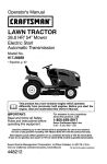
Mower Front Wheel
Mower
(2) Rear
Lift Link
Assemblies
(5) 1.3/16
O.D.
Washers
(1) Shoulder Bolt
(1) Small _
Retainer Springs
(5) Large
Retainer Springs
(1) Front _,
Lift Link
.'_\
Assembly
i , L,J,
")_
@
(1) Wheel
, Ji
(1) Oil DrainTube
if Equipped
(_
Keys
(1) Anti-Sway Bar
(1) 3/40.D.
Washers
(1) Small Retainer
Springs
(2) Keys
(t) 1-1/40.D.
Washer
@
(1)3/e-16
Locknut
Slope Sheet
Your new tractor has been assembled at the factory with exception of those parts left
unassembled for shipping purposes, To ensure safe and proper operation of your tractor
all parts and hardware you assemble must be tightened securely. Use the correct tools
as necessary to ensure proper tightness.
TOOLS REQUIRED FOR ASSEMBLY
ADJUST SEAT
A socket wrench set will make assembly
1. Sit in seat.
easier. Standard wrench sizes are listed.
2. Lift up adjustment lever (A) and slide seat
(2) 7/16" wrenches Utility knife
until a comfortable position is reached
which allows you to press clutch/brake
(1) 1/2" wrench
Tire pressure gauge
pedal all the way down,
(1) 3/4" wrench
Pliers
3, Release lever to lock seat in position.
(1) 3/4" socket w/drive ratchet
(I) 9/16" wrench
Flashlight
When right or left hand is mentioned in this
manual, it meanswhenyouareintheoperating
position (seated behind the steering wheel).
TO REMOVE TRACTOR FROM
CARTON
UNPACK CARTON
. Remove all accessible loose parts and
parts cartons from carton.
. Cut along dotted lines on all four panels
of carton. Remove end panels and lay
side panels flat.
• Remove mower and packing materials.
. Check for any additional loose parts or
cartons and remove.
BEFORE
REMOVING
FROM SKID
TO CHECK
NOTE: "Youmay now roll your tractor off the
skid. Followthe appropriate instruction below
to remove the tractor from the skid.
WARNING: Before starting, read, understand and follow all instructions in the
Operation section of this manual, Be sure
tractor is in a well-ventilated area. Be sure
the area in front of tractor is clear of other
people and objects.
TRACTOR
TO ROLL TRACTOR OFF SKID (See
Operation section for location and
function of controls)
1. Raise attachment lift lever to its highest
position.
2, Release parking brake by depressing
brake pedal,
3, Place freewheel control in disengaged
positionto disengagetransmission (See
"TO TRANSPORT" inthe Operation section of this manual).
4. Roll tractor forward off skid,
BATTERY
1, Lift hood to raised position.
NOTE: If this battery is put into service after
month and year indicated on label (label is
located between terminals) charge battery
for minimum of one hour at 6-10 amps. (See
"BATTERY" in Maintenance
section of this
manual for charging instructions).
•
Forbatteryand batterycableinstallationsee
"REPLACING
BATTERY" inthe"Service
and Adjustments" section inthis manual,
bel
8
TO INSTALL MOWER
1. Set parking brake lever and lower
attachment lift lever
o Depress clutch/brake pedal aif the way
down and hold+
. Pull parking brake lever up and hold,
release pressurefrom clutch!brake pedal,
then release parking brake lever. Pedal
should remain in brake position. Ensure
parking brake will hold tractor secure.
2. Assemble front gauge wheel (W) to
front of mower,
H. FrontMowerBracket X. ShoulderBolt
W. FrontGaugeWheel Y. 11AO.D.Washer
Z. 3/8+16Locknut
3. Turn steering wheel left and position
mower.
• Turnsteering wheel to the left as far as it
willgoandpositionmower onrightsideof
tractorwith deflectorshield(Q)tothe right.
Front
Brake Lever
_CAUTION:
Lift lever is spring loaded.
Have a tight grip on lift lever, lower it slowly
and engage in lowest position. Lift lever is
located on left side of fender.
Q, Deflector
Shield
A.
B+
C.
D.
E+
E
H.
I. Left Side Rear Mower Bracket
K. BeItTension Rod
Mower Side Suspension Arms
Retainer Spring
Rear Uft Unk(s)
Right Side Rear Mower Bracket
Front Uft Link Assembly
Front Suspension Bracket
Front Mower Bracket
L.
M.
Q+
S.
W.
9
Locking Bracket
Engine Clutch Pulley
Deflector Shield
Anti-Sway Bar
Front Gauge Wheel
4. Slide mower under tractor.
• Bring belt forward and check belt for
properrouting in all mower pulleygrooves,
NOTE: Be sure mower side suspension
arms (A) are pointing forward before sliding
mower under tractor,
• Slide mower under tractor until it is
centered under tractor.
Pivot the integrated washer end of antisway bar (S) towards mower deck bracket
on right side of mower, Insert integrated
washer end of bar into hole in rear mower
bracket (D). Move mower as needed to
insert integrated washer efld of bar into
rear mower bracket (D).
Secure with small washer and small
retainer spring as shown,
D. RightSide Rear
Mower
5. Install anti-sway bar (S) (If equipped)
Anti-Sway
Bar (S)
6. Attach mower side suspension arms
(A) to chassis.
• Positionfront hole in side suspension arm
(A) over pinon outsideoftractor chassis
and secure with large washer and large
retainer spring (B).
• Repeat on oppositeside of tractor.
Towards
Mower
Deck
d
90" End
Bracket
S. Anti-SwayBar
T, TransaxleBracket
IntegratedWasherEnd
From right side of mower, first insert
90 ° end of anti-sway bar (S) into hole in
transaxle bracket (T), located near left
rear tire in front of transaxle.
NOTE: Flashlight may be helpful.
Bar
_.,__=
............,.
I
Transaxle Bracket
Located Between Rear Tires
A, Mower Side Suspension Arms
B, Retainer Spring
D. Right Side Rear Mower Bracket
7. Attach rear lift links (C)
Insert rodend of rear liftlink (C) into hole
(U) in tractor lift shaft suspension arm
and pivot link down to mower.
° Lift rear corner of mower and position slot
in link assembly over pin on rear mower
bracket (D) and secure with largewasher
and large retainer spring.
• Repeat on opposite side of tractor.
T. TransaxleBracket
NOTE: Depending on model, bracket (T)may
be different than shown but hole for anti-sway
bar will be in same position/location.
10
9 Install Belt On Engine Clutch Pulley (M)
, Disengage belt tension rod (K) from
locking bracket (L).
° Install beltontoengine clutchpulley (M),
IMPORTANT: Check belt for proper routing in all mower puIley grooves and under
mandrel covers,
_ke(Sar)
Mower
Bracket
8 Attach front link (E)
• Turn steering wheel to position wheels
straight forward.
• From front of tractor, insert rod end of
front link (E) through front hole in tractor
front suspension bracket (F).
• Move to left sideof mower and and insert
large retainer spring (G) through hole in
front link (E) behind front suspension
bracket (F),
• Insert other end of link (E) into hole in
front mower bracket (H) and secure with
washer and small retainer spring (J).
NOTE: Requires deck lifting.
E.
E
G,
H,
J,
M.
Engage belt tension rod (K) on locking
bracket (L).
_ILCAUTION: Belt tension rod is spring
loaded. Have a tight grip on rod and
engage slowly,
- Raise attachment lift lever to highest
position.
• Ifnecessary,adjustgaugewheelsbefore
operatingmowerasshownintheownefs/
operator'smanual. Checkgaugewheels,
deck level and rake settings.
Front Lift Link Assembly
Front Suspension Bracket
Large Retainer Spring
Front Mower Bracket
Small Retainer Spring
Engine Clutch Pulley
11
CHECK TIRE PRESSURE
The tires on your tractor were over-inflated
at the factory for shipping purposes. Correct
tire pressure is important for best cutting
performance.
• Reducetire pressureto PSI shown ontires.
CHECK DECK LEVELNESS
For best cutting results, mower housing
should be properly leveled. See "TO LEVEL
MOWER" in the Service and Adjustments
section of this manual.
CHECKLIST
Before you operate your new tractor, we
wish to assure that you receive the best
performance and satisfaction from this
Quality Product.
Please review the following checklist:
J All assembly instructions have been
completed.
J" No remaining loose parts in carton.
_' Battery is properly prepared and
charged.
J" Seat is adjusted comfortably and tightened securely.
J All tires are properly inflated. (For shipping purposes, the tires were overinflated
at the factory).
J" Be sure mower deck is properly leveled
side-to-side/front-to-rear for best cutting
results. _ires must be properly inflated
for leveling).
J" Check mower and drive belts. Be sure
they are routed properly around pulleys
and inside all belt keepers.
J' Check wiring, See that all connections
are still secure and wires are properly
clamped.
!/" Before driving tractor, be sure freewheel
control is in "transmission engaged"
position (see "TO TRANSPORT" in the
Operation section of this manual).
CHECK FOR PROPER POSITION OF
ALL BELTS
See the figures that are shown for replacing
motion and mower blade drive belts in the
Service andAdjustments section of this manual, Verify that the belts are routed correctly.
CHECK BRAKE SYSTEM
After you learn how to operate your tractor,
check to see thatthe brake is operating properly. See"TO CHECKBRAKE" intheService
and Adjustments section of this manual.
While learning howto useyour tractor, payextra attention to the following important items:
J" Engine oil is at proper level,
J Fueltank isfilledwithfresh, clean, regular
unleaded gasoline.
-,/Become familiar with all controls, their
location and function. Operate them
before you start the engine.
Besure brake system is in safe operating
condition.
_" Be sure Operator Presence System and
Reverse Operation System (ROS) are
working properly (See the Operation and
Maintenance sections in this manual).
J' It is important to purge the transmission
before operating your tractor for the first
time. Follow proper starting andtransmission purging instructions (See 'q-OSTART
ENGINE"and"PURGETRANSMISSION"
inthe Operation section of this manual),
12
These symbols may appear on your tractor or in literature suppEiedwith the product.
Learn and understand their meaning.
R
N
REVERSE
H
NEUTRAL
i\!
L
HIGH
LOW
CHOKE
FAST
SLOW
IGNITION
ENGINE
OFF
LIGHTS
ON
REVERSE
OPERATION
SYSTEM (ROS)
FUEL
ATrACHMENT
CLUTCH
DISENGAGED
ENGINE
BATTERY
ON
ENGINE
REVERSE
A'rFACNMEN't"
CLUTCH
ENGAGED
START
PARKING
FORWARD
DANGER,
KEEP HANDS
AND FEET AWAY
BRAKE
CRUISE
KEEP
MOWER
AREA
OLFJ_R
(SEE
SAFE'r_
MOWER LIFT
HEIGHT
CONTROL
SWITCH
CLUTCH/BRAKE
PEDAL
SLOPE
RULES
HAZARDS
SECTION)
DANGER
will
result indicates
in death aorhazard
seriouswhich,
injury.if not avoided,
FREE
(Automstlo
WARNING
hazard
which,
if not avoided,
could resultindicates
in deatha or
serious
injury.
WHEEL
Models
only)
&
CAUTION
indicates
a hazard
which, injury.
if not avoided,
might
result
in minor
or moderate
CAUTION when used without the alert symbot,
indicates a situation that could result in damage
to the tractor and/or engine.
Failure to follow instructions
could result in serious injury or
death. The safety alert symbol
is used to identify safety information about hazards which can
result in death, serious injury'
and/or property damage.
HOT SURFACES indicates a hazard which,
if not avoided, could result In death, serious injury
and/or property damage.
FIRE indicates a hazard which, if not avoided,
could result in death, serious injury and/or
property damage.
13
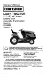
KNOW YOUR TRACTOR
READ THIS OWNER'S MANUAL AND SAFETY RULES BEFORE OPERATING YOUR
TRACTOR
Compare the illustrations with your tractor to familiarize yourself with the locations of
various controls and adjustments. Save this manual for future reference.
Our tractors conform to the applicable safety standards of the
American National Standards Institute.
(A) ATTACHMENT LIFT LEVER- Used to
raise and lower the mower or other attachmerits mounted to your tractor.
(B) BRAKE PEDAL- Used for braking the
tractor and starting the engine.
(C) PARKING BRAKE- Locks clutch/brake
pedal into the brake position.
(D) THROTTLE CONTROL- Used to control engine speed,
(E) ATTACHMENT CLUTCH SWITCH
- Used to engage the mower blades, or other
attachments mounted to your tractor.
(F) IGNITION SWITCH - Used for starting
and stopping the engine.
(G) REVERSE OPERATION SYSTEM
(ROS) "ON" POSITION- ALlows operation
of mower or other powered attachmentwhile
in reverse.
(H) LIGHT SWITCH - "liJrns the headlights
on and off.
(J) OR UISE CONTROL LEVER- Used to set
forward movement of tractor at desired speed
without holding the forward drive pedal
(K) FORWARD
DRIVE PEDAL - Used for
forward movement of tractor.
(L) REVERSE
DRIVE PEDALUsed for
reverse movement of tractor.
(N) CHOKE CONTROLUsed when starting
a cold engine.
(P) SERVICE REMINDER / HOUR METER
- indicates when service is required for the
engine and mower.
14
The operation of any tractor can result in foreign objectsthrown into the
eyes, which can result in severe eye damage. Always wear safety glasses
or eye shields while operating your tractor or performing any adjustments
or repairs. We recommend standard safety glasses or a wide vision safety
mask worn over spectacles.
ENGINE -
HOW TO USE YOUR TRACTOR
TO SET PARKING BRAKE
"Your tractor is equipped with an operator
presence sensing switch, When engine is
running, any attempt bythe operatorto leave
the seatwithout first setting the parking brake
will shut off the engine.
1. Depress brake pedal (B) all the waydown
and hold.
2. Pull parking brake lever (C) up and hold,
release pressure from brake pedal (B),
then release parking brake lever. Pedal
should remain in brake position. Make
sureparking brake will holdtractor secure,
• Movethrottle control (D) between halfand
full speed (fast) position.
NOTE: Failure to move throttle control between half and full speed (fast) position, before stopping, may cause engine to"backfire".
• Turn ignition key (F) to "STOP" position
and remove key. Always remove keywhen
leavingtractorto prevent unauthorized use.
• Never use choke (N) to stop engine.
IMPORTANT: Leaving the ignitionswitch in
any position other than "STOP" will cause
the battery to discharge and go dead.
NOTE: Under certain conditions when tractor
isstanding idle with the engine running, hot
engine exhaust gases may cause "browning" of grass. To eliminate this possibility,
always stop engine when stopping tractor
on grass areas.
_CAUTION:
Always stop tractor completely, as described above, before leaving
the operator's position.
STOPPING
MOWER BLADES ° To stop mower blades, move attachment
clutch clutch lever to disengaged position
TO USE THROI"rLE CONTROL (D)
Always operate engine at full speed (fast).
• Operating engine at less than full speed
(fast)reduces engine'soperatingefficiency.
• Full speed (fast) offers the best mower
performance,
(_).
(_1_1) Attachment
Clutch Control
"Engaged"
GROUND
(1"_1) Attachment
Clutch Control
"Disengaged"
DRIVE -
- To stop ground drive, depress brake pedal
all the way down,
IMPORTANT:
Forward and reverse drive
pedals return to neutral position when not
depressed,
TO USE CHOKE CONTROL (N)
Use choke controlwhenever youare starting
a cold engine. Do not use to start a warm
engine.
• To engage choke control, pull knob out.
Slowly push knob in to disengage.
15
TO MOVE FORWARD
AND BACKWARD
The direction and speed of movement is
controlled by the forward and reverse drive
pedals.
1, Start tractor
and release
parking
brake,
2. Slowly depress forward(K) or reverse(L)
drive pedal to begin movement, Ground
speed increases the further down the
pedal is depressed,
TO USE CRUISE CONTROL
The cruise control feature can be used for
forward travel only.
SYSTEM CHARACTERISTICS
The cruise control should only be used
while mowing or transporting on relatively
smooth, straight surfaces, Other conditions
such as trimming at slow speeds maycause
the cruise control to disengage. Do not use
the cruise control on slopes, rough terrian
or while trimmimg or turning.
• With forward drive pedal depressed to
desired speed, pull cruise control lever
(J) up and hold while lifting your foot off
the pedal, then release the lever.
To disengage the cruise control, depress the
brake pedal, tap on forward drive pedal or
push the cruise control lever down.
TO ADJUST
MOWER
CUTTING
The cutting height range is approximately
1" to 4". The heights are measured from the
groundtothebladetipwith the engine notrunning.These heights areapproximate and may
vary depending upon soil conditions, height
of grass and types of grass being mowed.
• The average lawn should be cut to approximately 2-1/2" during the cool season
and to over 3" during hot months. For
healthier and better looking lawns, mow
often and after moderate growth.
• For best cutting performance, grass over
6" in heightshould be mowed twice. Make
the first cut relatively high; the second to
desired height.
TO ADJUST GAUGE WHEELS
Gauge wheels are properlyadjusted when
they are slightly offthe ground when mower
is at the desired cutting height in operating
position. Gauge wheels then keep the deck
in proper positionto help prevent scalping
in most terrain conditions.
NOTE: Adjust gauge wheels with tractor on
a flat level surface.
1. Adjust mower to desired cutting height
(See "TO ADJUST MOWER CUTTING
HEIGHT" in this section of manual).
2. With mower in desired height of cut position. gauge wheels should be assembled
so they are slightly off the ground, Install
gauge wheel inappropriate hole. Tighten
securely.
3. Repeat for all, installing gauge wheel in
same adjustment hole.
HEIGHT
The position of the attachment lift lever (A)
determines the cutting height,
• Put attachment lift lever in desired cutting
height slot.
• Slide pointer tab (T) to desired cutting
height as a reminder for next timeyou mow.
TO OPERATE MOWER
Your tractor is equipped with an operator
presence sensing switch. Any attempt bythe
operator to leave the seat with the engine
running and the attachment clutch engaged
wilt shut off the engine. You must remain
fully and centrally positioned in the seat to
preventthe enginefrom hesitating or cutting
offwhen operating your equipment on rough,
rolling terrain or hills.
1. Select desired height of cut with attachment lift lever.
2. Start mower blades by engaging attachment clutch control.
16
TO STOP MOWER BLADES
Disengage attachment clutch control.
_CAUTION:
Do not operate the mower
without either the entire grass catcher, on
mowers so equipped, orthe deflector shield
iS) in place.
REVERSE OPERATION SYSTEM (ROS)
Your tractor is equipped with a Reverse
Operation System (ROS). Any attempt by
the operator to travel in the reverse direction
with the attachment clutch engaged will shut
off the engine uniess ignition key is placed
in the ROS "ON" position.
_WARNING:
Backing up with the attachment clutch engaged while mowing is
strongly discouraged. Turningthe ROS"ON",
to allow reverse operation with the attachment clutch engaged, should only be done
when the operator decides it is necessary to
reposition the machine with the attachment
engaged. Do not mow in reverse unless
absolutely necessary.
USINGTHE REVERSEOPERATIONSYSTEM
Only use ffyou are certain no children or other
bystanders will enter the mowing area.
1. Depress brake pedal all the way down.
2. With engine running, turn ignition key
counterclockwise to ROS "ON" position.
3. Look down and behind before and while
backing.
4. Slowly depress reverse drive pedal to
start movement.
5. When use of the ROS is no longer
needed, turn the ignition key clockwise
to engine "ON" position.
ROS
"ON ° Posilion
Engine "ON" Position
(Normal Operating)
e
17
TO OPERATE ON HILLS
AI_WARNING: Do not drive up or down
hillswith slopes greater than ! 5° and do not
drive across any slope. Use the slope guide
provided at the back of this manual.
• Choose the slowest speed before starting
up or down hills.
• Avoid stopping or changing speed on
hills.
- If stepping is absolutely necessary, push
brake pedal quickly to brake position and
engage parking brake,
• Torestart movement, slowly release parking brake and brake pedal.
• Slowly depress appropriate drive pedalto
slowest setting.
• Make a]l turns slowly.
TO TRANSPORT
When pushing or towing your tractor, be
sure to disengage transmission by placing
freewheel control in freewheeling position.
Free wheel control is located at the rear
drawbar of tractor.
• Raise attachment lift to highest position
with attachment lift control.
• Pull freewheel controlout and into the slot
and release so it is held inthe disengaged
position.
- Do not push or tow tractor at more than
two (2) MPH.
• To reengagetransmission, reverseabove
procedure.
NOTE: To protect hood from damage when
transporting yourtractor on atruckor atrailer,
besure hood isclosed and secured totractor.
Use an appropriate means of tying hood to
tractor (rope, cord, etc.).
TOWING CARTS AND OTHER ATTACHMENTS
Tow only the attachments that are recommended by and comply with specifications
of the manufacturer of your tractor. Use
common sense when towing. Too heavy of
a load, while on a slope, isdangerous. Tires
can lose traction with the ground and cause
you to lose control of your tractor.
SERVICE REMINDER/HOUR METER
Service reminder shows the total number
of hours the engine has run and flashes to
indicatethat the engine or mower needs servicing, When service is required, the service
reminder will flash for two hours. To service
engine and mower, see the Maintenance
section of this manual.
NOTE: Service reminder runs when the
ignition key is in any position but "STOP".
For acurate reading, be sure key remains
in the "STOP" position when engine is not
running.
BEFORE STARTING THE ENGINE
CHECK ENGINE OIL LEVEL
The engine inyour tractor has been shipped,
from the factory, already filled with summer
weight oil.
1, Check engine oil with tractor on level
ground.
2. Unthread and remove oil fill cap/dipstick;
wipe oil off. Reinsert the dipstick into the
tube and rest oil fill cap on the tube. Do
not thread the cap onto thetube. Remove
and read oil level. If necessary, add oil
until "FULl" mark on dipstick is reached.
Do not overfill,
3. For cold weather operation you should
change oil for easier starting (See the oil
viscosity chart in the Maintenance section
of this manua D,
4. Tochange engine oil,seethe Maintenance
section in this manual.
5. Fill fuel tank to bottom of filler neck. Do
not overfill. Use fresh, clean, regular
unleaded gasoline with a minimum of
87 octane. (Use of leaded gasoline will
increase carbon and lead oxide deposits
and reduce valve life). Do not mix oil
with gasoline. Purchase fuel in quantities that can be used within 30 days to
assure fuel freshness.
CAUTION: Wipe off any spilled oil or
, Do not store, spill or use gasoline
near an open flame.
IMPORTANT: When operating in temperatures below 32°F(0°C), use fresh, clean
winter grade gasoline to help ensure good
cold weather starting.
18
CAUTION: Alcohoi blended fuels (called
gasohoI or using ethanol or methanol) can
attract moisture which leads to separation
and formation of acids during storage. Acidic
gas can damage thefueI system of an engine
while in storage. To avoid engine problems,
the fuel system should be emptied before
storage of 30 days or longer. Drain the gas
tank, start the engine and tat it run until the
fuel linesand carburetor are empty. Usefresh
fuel next season. See Storage Instructions
for additional information, Never use engine
or carburetor cleaner products inthe fueitank
or permanent damage may occur.
RESERVE FUEL VALVE OPERATION
1. Raise seat to access reserve fuel
valve.
2. in normal operation,valve should be
set to primary(as shown in view)
3. If tractor runsout of fuel, rotatevalve
handle to reserve.
4. Drive tractor to be refueled.
5. After refueling, return valve to primary
position.
ReseFv'e
FuelValve
@
Primary
TO START ENGINE
When starting the engine for the first time or
if the engine has run out of fuel, it will take
extra cranking time to move fuel from the
tank to the engine,
1, Be sure freewheel control isin the transmission engaged position.
2. Siton seat in operating position, depress
brake pedal and set parking brake.
3. Move attachment clutch to disengaged
position.
4. Move throttle control to fast position
5. Pull choke control out for a c01dengine
start attempt. For a warm engine start
attempt the choke control may not be
needed.
NOTE: Before starting, read the warm and
cold starting procedures below.
6. Insert key into ignition and turn key
clockwise to start position and release
key as soon as engine starts. Do not run
starter continuously for more than fifteen
seconds per minute, if the engine does
not start after several attempts, push
choke control in, wait afew minutes and
try again. If engine stiJl does not start,
puil the choke control out and retry.
WARM WEATHER STARTING
(50°F (10°C) and above)
7. When engine starts, slowJy push choke
control in until the engine begins to run
smoothly. If the engine starts to run
roughly, pulfthe choke controlout slightly
for a few seconds and then continue to
push the control in slowly.
• The attachments and ground drive
can now be used, If the engine does
not accept the load, restart the engine
and allow it to warm up for one minute
using the choke as described above.
COLD WEATHER STARTING
(50°F (10°C) and below)
7. When engine starts, slowly push choke
contro] in until the engine begins to run
smoothly. Continue to push the choke
control insmall steps allowing the engine
to accept small changes in speed and
toad, until the choke control is fully in.
If the engine starts to run roughly, pull
the choke control out slightly for a few
seconds and then continue to push the
control in slowly. This may require an
engine warm-up period from several
seconds to several minutes, depending
on the temperature.
AUTOMATIC TRANSMISSION WARM UP
Before driving the unit in cold weather, the
transmission should be warmed up as follows:
1, Be sure the tractor is on level ground,
2. Release the parking brake and let the
brake slowly return to operating position.
3. Allow one minute for transmission to
warm up, This can be done during the
engine warm up period,
• The attachments can be used during
the engine warm-up period after the
transmission has been warmed up
and may require the choke control be
pulled out slightly.
NOTE: Ifat a high altitude (above 3000 feet)
or in cold temperatures (below 32°F (0°C))
the carburetor fuel mixture may need to be
adjusted for best engine performance (see
"TO ADJUST CAR BU RETOR" inthe Service
and Adjustments section of this manual).
19
PURGE TRANSMISSION
_I_CAUTION: Never engage or disengage
freewheel lever while the engine is running.
Toensure properoperation andperformance,
it is recommended that the transmission be
purged before operating tractor for the first
time. This procedure willremove anytrapped
air reside the transmission which may have
developed during shippingof your tractor.
IMPORTANT: Should your transmission
require removal for service or replacement,
it should be purged after reinstallation before
operating the tractor.
1. Place tractor safely on a level surface that is clear of objects and open - with
engine off and parking brake set,
2. Disengage transmission
by placing
freewheel control indisengaged position
(See "TO TRANSPORT" in this section
of manual).
3. Sitting in the tractor seat, start engine.
After the engine isrunning, move throttle
control to slow position. Disengage parking brake.
_CAUTION:
At any time, during step 4,
there may be movement of the drive wheels,
4. Depress forward drive pedalto full forward
position and hold forfive (5) seconds and
release pedal. Depress reverse drive
pedal to full reverse position and hold
for five (5) seconds and release pedal.
Repeat this procedure three (3) times.
5, Shutoff engine and set parking brake.
6. Engage transmission by placing freewheel control in engaged position (See
"TO TRANSPORT" in this section of
manual).
7. Sitting in the tractor seat, start engine.
After the engine is running, move throttle
control to half (1/2) speed. Disengage
parking brake.
8. Drive tractor forward for approximately
five feet then backwards for five feet,
Repeat this driving procedure three
times.
Your transmission is now purged and now
ready for normal operation.
MOWING
TIPS
• Tire chains cannot be used when the
mower housing is attached to tractor.
• Mower should be properlyleveled for best
mowing performance. See "TO LEVEL
MOWER HOUSING" in the Service and
Adjustments section of this manual.
• The left hand side of mower should be
used for trimming.
• Drive so that clippings are discharged onto
the area that has already been cut, Have
the cut area to the right of the tractor. This
will result in a more even distribution of
clippings and more uniform cutting.
• When mowing largeareas, start byturning
to the right so that clippings will discharge
away from shrubs, fences, driveways,
etc. After one or two rounds, mow in the
opposite direction making [eft hand turns
until finished.
f
J
• if grass is extremely
tall, it should be
mowed twice to reduce load and possible
fire hazard from dried clippings,
Make
first cut relatively high; the second to the
desired height.
• Do not mow grass when it is wet. Wet
grass will plug mower and leave undesirable c]umps.
Allow grass to dry before
mowing.
• Always operate engine at full throttle
when mowing to assure better mowing performance
and proper discharge
of material.
Regulate ground speed by
selecting a low enough speed to give the
mower cutting performance as well as the
quality of cut desired.
• When operating
attachments,
select a
ground speed that will suit the terrain and
give best performance
of the attachment
being used.
20
AINTENANCE
BEFORE
F.ACH
SCHEDULE
Check,Brake
Check
Tire
Operation
Peessure
Check Operelor
,,
Presence & ROS Systems
A
Check for Loose Fasteners
C
CheekJRep_ace
T
Lubrication
0
Check
R
CIe an Balte
Mower
EVERY
S
use
V'
_'_
V'
I/"
fk/
EVERY
25
Check
Tmnsaxle
......
Off
' '_
I
V
V*_
,,.
....
Terminals
V
Plate,
"
Coo,_,ing
....
V'
_
,
f
_
,
, ,
V"
Check Mower Levelness
V _''
Check V-Belts
Check
,,,
Oil
Engine
Change
Enql_ne
Change
Engine
Level
_,,,
E
Clean Air Fitter
Clean
"'_
Oil (with oil filter)
Oi| (without
G
|
V'_'._
oil filte,r)
V"
V'I,Z
J
_
.......
_.
AirScreen
Inspect
V'=
Mull]el/Spark
Arrester
i_
N i Replace Oil Filter (1!equipped)
_#_'=
E
V'2
C ean
Rep
,Engine
age
Re,place
Replace
Coolin_
Fins
Spe, rk Plug
Air Filter
Fuel
""
........
Blades
Steering
BEFORE
STORAGE
,
If
ry and
Oebrie
EVERY
SEASON
..
if
Level
Clean
EVERY
t00
'
Cha_t
Battery
EVERY
50
HOURSHOURS HOURSHOURS
Paper
Filter
V
Cartridge
=......
I_"
_t_
....
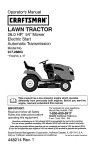
LUBRICATION CHART
GENERAL RECOMMENDATIONS
The warranty on thistractor does not cover
items that have been subjected to operator
abuse or negligence. To receive futlvalue
from the warranty, operator must maintain
tractoras instructedin this manual.
Some adjustments willneed to be made periodicallyto properly maintain your tractor.
At least once a season, check to see if
you should make any of the adjustments
described in the Service and Adjustments
section of this manual.
• At least once a year you should replace
the spark plug, clean or replace air filter,
and check blades and belts for wear. A
new spark plug and clean air filter assure
proper air-fuel mixture and help your engine run better and last longer.
BEFORE EACH USE
t, Check engine oil leve!,
2. Check brake operation.
3, Check tire pressure,
4. Check operator presence and
ROS systems for proper operation,
5, Check for loose fasteners,
(_SteeringPivotBolts
(_ Spindle----iF/_l_
Spindle
_Front I-
'12_41
"_.... [L..LJ"0 FrontWheel
_=____?earing
Zerk
Sector
[[
_.','_--_I
ix{
Teeth
L._
_
Gear
I Id_:_d.?._F:IIX
;":
_
\_)Mandrel
Zerks
OGeneral Purpose Grease
(_)Referto Maintenance"ENGINE" Section.
IMPORTANT: Do not oilor grease the pivot
points which have special nylon bearings.
Viscous lubricants will attract dust and dirt
thatwill shorten the lifeof the self-lubricating
bearings, Ifyou feel they must be lubricated,
use only a dry, powdered graphite type lubricant sparingly.
21
TRACTOR
Always observesafety ruleswhen performing
any maintenance.
BRAKE OPERATION
If tractor requires more than five (5) feet to
stop at highest speed in highest gear on a
level, dry concrete or paved surface, then
brake must be serviced. (See "TO CHECK
BRAKE" in the Service and Adjustments
section of this manual).
TIRES
* Maintain proper air pressure in all tires
(See PSI on tires).
- Keep tires free of gasoline, oil, or insect
control chemicals which can harm rubber.
° Avoid stumps, stones, deep ruts, sharp
objects and other hazards that may cause
tire damage.
NOTE: To seal tire punctures and prevent
flat tires due to slow leaks, tire sealant may
be purchased from your local parts dealer.
Tire sealant also prevents tire dry rot and
corrosion.
OPERATOR PRESENCE SYSTEM AND
REVERSE OPERATION SYSTEM (ROS)
Be sure operator presence and reverse
operation systems are working properly. If
your tractor does not function as described,
repair the problem immediately.
. The engine should not start unless the
brake pedal is futty depressed, and the
attachment clutch control is in the disengaged position.
CHECK
OPERATOR
PRESENCE
SYSTEM
• When the engine is running, any attempt
by the operator to leave the seat without
first setting the parking brake should shut
off the engine.
• When the engine is running and the attachment clutch is engaged, any attempt
by the operator to leave the seat should
shut off the engine,
. The attachment clutch should never operate unless the operator is in the seat.
ROS "ON" Position
Engine "ON" Position
(Normal Operating)
22
CHECK REVERSE OPERATION (ROS)
SYSTEM
• When the engine isrunning withtheignition
switch inthe engine "ON" position and the
attachment clutch engaged, any attempt
bythe operator to shift into reverse should
shut off the engine.
• Whenthe engine is running withthe ignition
switch in the ROS "ON" position and the
attachment clutch engaged, any attempt
by the operator to shift into reverse should
NOT shut off the engine.
BLADE CARE
For best results mower blades mustbe sharp.
eptace worn, bent or damaged blades.
CAUTION: Useonly a replacement blade
approved bythe manufacturer of yourtractor.
Using a blade not approved by the manufacturer of your tractor is hazardous, could
damage your tractor and void your warranty.
BLADE REMOVAL
1. Raise mowerto highest positiontoallow
access to blades,
NOTE: Protect your handswith gloves and/
or wrap blade with heavy cloth.
2, Remove blade bolt by turning countercloct{wise,
3. InstalInewbladewithstamped"THIS SIDE
UP" facing deck and mandrel assembly,
IMPORTANT: To ensure proper assembly,
center hole in blade must align with star on
mandrel assembly.
4. Install and tighten blade bolt securely
(45-55 Ft, Lbs. torque).
IMPORTANT: Special blade bolt is heat
treated.
Mandrel
Assembly
BATTERY
Center _lole _,_
Your tractor has a battery charging system
which is sufficientfor normal use. However,
periodic charging of the battery with an automotive charger will extend its life.
• Keep battery and terminals clean.
• Keep battery bolts tight.
• Keep small vent holes open.
• Recharge at 6-10 amperes for 1 hour.
NOTE: The original equipment battery on
your tractor is maintenance free. Do not
attempt to open or remove caps or covers.
Adding or checking level of electrolyte is
not necessary.
TOCLEAN
BATTERY
ANDTERMINALSChange the oil after every 50 hours of opor at least once a year ff the tractor
Corrosion
anddirtonthebatter]
andtermi- eration
not used for 50 hours in one year.
nalscancause
thebattery
to"leak"
power. isCheck
the crankcase oil level before start1. Remove
terminal
guard.
2. Disconnect
BLACK
battery
cablefirst ing the engine and after each eight (8)
thenREDbatterycableandremove hours of operation.
battery
fromtractor.
TO CHANGE ENGINE OIL
3. Rinsethe
batterywith
plain
water
anddry. Determine temperature range expected
4. Clean
terminals
andbattery
cableends before oil change. All oil must meet APf
withwirebrush
untilbright.
classificationSG-SL.
5. Coat
terminals
withgrease
orpetroleumservice
• Be sure tractor is on level surface.
jelly.
• Oil will drain more freely when warm.
6, Reinstall
battery(See"REPLACING
oil in a suitable container.
BATTERY"
intheSERVICE
ANDAD- •I. Catch
oil fill cap/dipstick. Be careful
JUSTMENTS
section
ofthismanual). Remove
not to allow dirt to enter the engine when
TRANSAXLE MAINTENANCE
Thetransmission fan and coolingfins should
be kept clean to assure proper cooling. Do
notattempt to clean fan ortransmissionwhile
engine is running or while the transmission
is hot. To prevent possible damage to seals,
do not use high pressure water or steam to
clean transaxle.
• Inspect cooling fan to be sure fan blades
are intactand clean.
• Inspectcooling fins for dirt, grass clippings
and other materials. Toprevent damageto
seats, do not use compressed air or high
pressure sprayer to clean cooling fins.
TRANSAXLE PUMP FLUID
The transaxle was sealed at the factory and
fluid maintenance is not required for the life
of the transaxle. Should the transaxle ever
leak or require servic!ng, contact your nearest Sears or other qualified service center.
changing oil.
2. Remove yellow cap from end of drain
valve and install the drain tube onto the
fitting.
3. Unlock drain valve by pushing inward
slightly and turning counterclockwise.
Oil Drain Valve
YellowCap_
4. To open, pull out on the drain valve.
5. Afteroil has drained comp[etely, close and
lock the drain valve by pushing inward
and turning clockwise until the pin is in
the locked position as shown.
6. Remove the drain tube and replace the
cap onto the end of the drain valve.
7. Refill engine with oilthrough oilfi!l dipstick
tube. Pour slowly. Do not overfill. For
approximate capacity see "PRODUCT
SPECIFICATIONS"sectionofthis manual.
8. Use gauge on oil fib cap!dipstick for
checking level. Insert dipstick into the
tube and rest the oil fill cap on the tube.
Do notth read the cap onto the tube when
taking reading. Keep oil at "FULL_'line
on dipstick. Tighten cap onto the tube
securely when finished.
V-BELTS
Check V-belts for deterioration andwearafter
100 hours of operation and replace ff necessary. The belts are not adjustable. Replace
belts if they begin to slip from wear.
ENGINE
LUBRICATION
Only use high quality detergent oil rated
with API service classification SG-SL.
Select the oil's SAE viscosity grade
according to your expected operating
temperature.
23
AIR FILTER
Your engine will not run properly using a
dirty air filter, Service paper cartridge every
two months or every 25 hours of operation,
whichever occurs first,
Service paper cartridge more often under
dusty conditions.
Replace the paper cartridge annually, or after
every 100 hours of operation,
TO SERVICE CARTRIDGE
• Replace a dirty, bent, or damaged cartridge. Handle new cartridge carefully; do
not use if the rubber seal is damaged,
NOTE: Do not wash the paper cartridge
or use pressurized air, as this will damage
the cartridge.
1. Open door (A) on the blower housing to
access the air cleaner element (B).
2.
3.
4.
5.
6.
Unhook the latch
element.
(C) and remove the
CLEAN AIR SCREEN
Air screen must be kept free of dirt and chaff
to prevent engine damage from overheating,
Clean with awire brush or compressed air to
remove dirt and stubborn dried gum fibers.
CLEAN AIR INTAKE/COOLING AREAS
To ensure proper cooling, make sure the
grass screen, cooling fins, and other external surfaces of the engine are kept clean
at all times.
Every 100 hours of operation (more often
under extremely dusty, dirty conditions),
remove the blower housing and other cooling
shrouds. Clean the cooling fins and external
surfaces as necessary. Makesurethe cooling
shrouds are reinstalled.
NOTE: Operating the engine with a blocked
grass screen, dirty or plugged cooling fins,
and!or cooling shrouds removed will cause
engine damage due to overheating.
MUFFLER
Inspect and replace corroded muffler and
spark arrestor (if equipped) as it could create
a fire hazard and/or damage.
SPARK PLUG(S)
Replace spark plug(s) at the beginning of
each mowing season or after every 100
hours of operation, whichever occurs first.
Spark plug type and gap setting are shown
in "PRODUCT SPECIFICATIONS" section
of this manual.
IN-LINE FUEL FILTER
The fuel filter should be replaced once each
season. If fuel filter becomes clogged, obstructing fuel flowto carburetor, replacement
is required.
1. With engine cool, remove filter and plug
fuel line sections.
2. Place new fuel filter in position infuel line
with arrow pointing towards carburetor.
3. Be sure there are no fuel line leaks and
clamps are properly positioned.
4, Immediately wipe up anyspilled gasoline.
Gentlytap the paper element to dislodge
dirt.
Clean all air cleaner components of any
accumulated
dirt or foreign
material.
Prevent any dirt from entering the throat
of carburetor.
Install cleaned or new element on the
base and secure with latch.
Close and latch the door.
Ctam_amp
Fuel Filter _.__J_
24
yd_
I
CLEANING
• Clean engine, battery, seat, finish, etc.
of all foreign matter.
• Clean debris from steering plate.
Debris can restrict clutch/brake pedal
shaft movement, causing belt slip and
loss of drive.
CAUTION: Avoid all pinch points and
movable parts
Clutch/brake
pedal
4.
Steering System, Dash,
Fender and Mower l_ot Shown
Pull back the lock collar of the nozzle
adapter and push the adapter onto the
deckwashout port at the left end of the
mower deck. Release the lock collar to
lock the adapter on the nozzle.
IMPORTANT: Tug hose ensuring connection is secure.
5. Turn the water on.
6. While s_ng in the operator's position
on the tractor, re-start the engine and
place the throttle lever in the Fast ",_"
position.
IMPORTANT: Recheck the area making
certain the area is clear.
7. Move the tractor's attachment clutch
control to the "ENGAGED" position.
Remain in the operator's position
with the cuttingdeck engaged untilthe
deck is cleaned.
8. Move the tractor's attachment clutch
control to the "DISENGAGED" position. Turnthe ignitionkey to the STOP
positionto turnthe tractor'sengine off.
Turn the water off.
9. Pull back the look collar of the nozzle
adapter to disconnectthe adapter from
the nozzle washout port.
10. Move the tractor to a dry area, preferably a concrete or paved area. Place
the attachment clutch control in the
"ENGAGED" positionto removeexcess
water andto help dry beforeputtingthe
tractoraway.
_WARNING: A brokenor missingwashout
fittingcould exposeyou or othersto thrown
objectsfrom contactwith the blade.
Replacebrokenor missingwashoutfitting
immediately,prior to using moweragain.
* Plug any holes in mower with bolts and
lock,
nuts,
CAUTION:
_Z_ Pinch
4131=Points
•
Keep finished surfaces and wheels
free of all gasoline, oil, etc.
° Protect painted surfaces with automotive type wax.
We do not recommend using a garden hose
or pressure washer to clean your tractor
unless the engine and transmission are
covered to keep water out, Water in engine
or transmission will shorten the useful life of
your tractor. Use compressed air or a leaf
blower to remove grass, leaves and trash
from tractor and mower.
DECK WASHOUT PORT
Your tractor's deck is equipped with a
washout port on its surface as part of its
deck wash system. It should be utilized after each use.
1. Drive the tractor to a level, clear spot
on your lawn, near enough to a water
spigot for your garden hose to reach.
IMPORTANT: Make certain the tractor's
discharge chute is directed AWAY from your
house, garage, parked cars, etc. Remove
bagger chute or mulch cover if attached.
2. Make sure the attachment clutch control
is in the "DISENGAGED" position,set
the parking brake, and stop the engine.
3. Thread the nozzle adapter (packaged
with your tractor's Operator's Manual)
onto the end of your garden hose.
25
t,
3,
4,
5.
6.
WARNING: TO AVOIDSERIOUS INJURY, BEFORE PERFORMING
ANY SERVICEOR
ADJUSTMENTS:
Depress clutch/brake pedal fully and set parking brake.
Place attachment clutch in "DISENGAGED" position.
Turn ignitionkey to "STOP" and remove key.
Make sure the blades and all moving partshave completely stopped.
Disconnect spark plug wire from spark plug and place wire where it cannot come
in contact with plug.
TO REMOVE MOWER
1, Place attachment clutch in "DISENGAGED" position,
2. Lower attachment lift lever to its lowest
position.
3. Disengage belttension rod (K) from lock
bracket (L).
_, CAUTION: Belt tension rod is spring
loaded. Have a tight grip on rod and release
slowly.
4. Remove mower belt from electric clutch
pulley (M).
5. Disconnect front link (E) from mowerremove retainer spring and washer.
6, Go to either side of mower and disconnect
mower suspension arm (A) from chassis and rear lift link (O) from rear mower
bracket (D) - remove retainer springs and
washers,
7. Go to othersideof mower anddisconnect
the suspension arm and rear lift link.
26
_lb CAUTION: After rear lift links are disconnected, the attachment lifflever will bespring
leaded. Have a tight grip on lift lever when
changing position of the lever.
8. From right side of mower, disconnect
anti-sway bar (S) from right rear mower
bracket (D) - remove retainer spring and
washer and pull mower toward you until
the bar falls from the hole in bracket.
9. Turn tractor steering wheel to the left as
far as it will go.
10, Slide mower out from under right side of
tractor.
TO INSTALL MOWER
Follow procedure described in "INSTALL
MOWERAND DRIVE BELT" intheAssembly
section of this manual.
TO LEVEL MOWER
Make sure tires are properly inflatedto the
PSi shown on tires, lftires are over or under
inflated, it may affect the appearance of your
lawn and lead you to think the mower is not
adjusted properly,
VISUAL SIDE-TO-SIDE ADJUSTMENT
1. With all tires properly inflated and if your
lawn appears unevenly cut, determine
which side of mower is cutting lower.
NOTE: As desired, you can raise the low
side of mower or lower the high side.
2. Go to side of mower you wish to adjust.
3. With a 3/4" or adjustable wrench, turn
lift link adjustment nut (A) to the left to
lower the mower, or, to the right to raise
the mower.
Turn nut right
to raise mower
Turn nut left
lower mower
NOTE: Each full turn of adjustment nut will
change mower height about 3/16".
4. Test your adjustment by mowing some
uncut grass and visually checking the
appearance. Readjust, ifnecessary, unti/
you are satisfied with the results.
PRECISION SIDE-TO-SIDE ADJUSTMENT
1. Wtth alltires properly inflated, parktractor
on level ground or driveway.
_I, CAUTION: Blades are sharp. Protect
your hands with g]oves and/or wrap blade
with heavy cloth.
2. Raise mower to its highest position.
3. At both sides of mower, position blade at
side and measure the distance (A) from
bottom edge of blade to the ground. The
distanceshould bethesameon bothsides.
27
4, If adjustment is necessary, see steps 2
and 3 in Visual Adjustment instructions
above.
5. Recheck measurements, adjust if necessary until both sides are equal.
FRONT-TO-BACK ADJUSTMENT
IMPORTANT: Deck must be level sideto-side.
To obtain the best cutting results, the mower
blades should be adjusted so the front tip is
1/8" to 1/2" lower than the rear tip when the
,_ower is in its highest position.
CAUTION: Blades are sharp. Protect
your hands with gloves and/or wrap blade
with heavy cloth.
• Raise mower to highest position.
• Position any blade so the tip is pointing
straight forward. Measure distance (B) to
the ground atfront and rear tip ofthe blade.
• If fronttip of blade is not 1/8" to 1/2" lower
than the rear tip, go to the front of tractor.
• With an 111'16" or adjustable wrench,
loosen jam nut A several turns to clear
adjustment nut B.
• With a 3/4" or adjustable wrench, turn
front link adjustment nut (B) clockwise
(Itighten) to raise the front of mower, or,
counterclockwise (loosen) to lower the
front mower.
Tighten adjust nut
B to raise mower
Loosen adjust
nutB tetower
mower
Loosenjam nutA first
NOTE: Each full turn of the adjustment nut
will change mower height about 1/8".
° Recheck measurements, adjust if necessary until front tip of blade is 1/8" to 1/2"
lower than the rear tip.
• Hold adjustment nut inposition with wrench
and tighten jam nut securely against adjustment nut.
TO REPLACE MOWER DRIVE BELT
MOWER DRIVE BELT REMOVAL
I. Park tractor on a level surface, Engage
parking brake,
2, Lower attachment lift lever to its lowest
position.
3. Disengage belt tension rod (K) from lock
boracket(L).
AUTION: Belttension rod isspring loaded. Have afirm grip on rod and releaseslowly.
4. Remove screws (P) from R.H. and L.H,
mandrel covers and remove covers (Q).
5. Remove anydirt or grass clippings which
may have accumulated around mandrels
and entire upper deck surface.
6, Remove belt from electric clutch pulley
(M), both mandrel pulleys (R) and all idler
pulleys (S),
MOWER DRIVE BELT INSTALLATION
1. Install belt around both mandrel pulleys
(R) and around idler pulleys (S) as shown.
2. Install belt onto electric clutch pulley (M).
IMPORTANT: Check belt for proper routing
in all mower pulley grooves,
3. Reassemble R.H. and LH. mandrelcovers (Q). Securely tighten all screws.
4, Engage belt tension rod (K) on locking
bracket (L).
_CAUTION: Betttension rod isspring loaded, Have aright grip on rodand engageslowly.
5. Raise attachment lift lever to highest
position,
TO REPLACE MOTION DRIVE BELT
Park the tractor on level surface, Engage
parking brake, For assistance, there is a
belt installation guide decal on bottom side
of left footrest.
BELT REMOVAL
1. Remove
MOWER"
-
mower (See "TO REMOVE
in this section of manual).
28
NOTE: Observe entire motion drive belt and
position of all belt guides and keepers,
2, Disconnect clutch wire harness (A).
3. Remove anti-rotation link (B) on rightside
of tractor,
4. Remove beltfrom stationary idler (C) and
clutching idler (D).
5, Pull belt slack toward rear of tractor.
Carefully remove belt upwards from
transmission inputpulley and over cooling fan blades (F).
6. Remove belt downward from engine
pulley and around electric clutch (G),
7, Slide belt toward rear of tractor, off the
steering plate (H) andremove fromtractor,
BELT INSTALLATION 1, Install new belt from tractor rear to front,
over the steering plate (H) and above
clutch brake pedal shaft (J),
2. Pull belttowardfront oftractor and roll belt
around electric clutch and onto engine
pulley (G),
3. Pull belt toward rear of tractor. Carefully
work belt down around transmission
cooling fan and onto the input pulley (F).
Be sure belt is inside the belt keeper,
4, Install belt through stationary idler (C)
and clutching idler (D).
5. Reinstall anti-rotation link (B) on right
side of tractor. Tighten securely.
6. Reconnect clutch harness (A),
7. Make sure belt is in all pulley grooves
and inside all belt guides and keepers.
8, Install mower (See "TO INSTALL MOWER" in this section of manual),
TO CHECK BRAKE
tf tractor requires more than five (5) feet to
stop at highest speed in highest gear on a
level, dry concrete or paved surface, then
brake must be serviced.
You may also check brake by:
1. Park tractor on a level, dry concrete or
paved surface, depress brake pedal a!l
the waydown and engage parking brake.
2. Disengage transmission
by placing
freewheel control in "transmission disengaged" position. Pull freewheel control
out and into the slot and release so it is
held in the disengaged position.
The rear wheels must lock and skid when
you try to manually push the tractor forward.
If the rear wheels rotate, then the brake
needs to be serviced. Contact a Sears or
other qualified service center.
FRONT WHEEL TOE-IN/CAMBER
Your new tractor front wheel toe-in and camber is set at the factory and is normal. The
front wheel toe-in and camber are not adjustable. If damage has occurred to affect the
factory set front wheel toe-in or camber, contact aSears or other qualified service center.
TO REMOVE WHEEL FOR REPAIRS
1. Block up axle securely.
2. Remove axle cover, retaining ring and
washers to allow wheel removal (rear
wheels have a square key- Do not lose).
3. Repair tire and reassemble.
NOTE; On rear wheels only: align grooves in
rear wheel hub and axle. Insertsquare key.
4. Replace washers and snap retaining ring
securely in axle groove.
5. Replace axle cover.
NOTE: To seal tire punctures and prevent
fiat tires due to slow leaks, purchase and
use tire sealantfrom Sears. Tire sealantalso
prevents tire dry rot and corrosion.
TO START ENGINE WITH A WEAK BATTERY
A(_WARNING: Lead-acid batteries generate explosive gases. Keep sparks, flame
and smoking materials away from batteries.
Always wear eye protection when around
batteries.
Ifyour battery istooweakto startthe engine, it
should be recharged. (Sea"BATTER'{" inthe
MAINTENANCE section of this manual),
If "jumper cables" are used for emergency
starting, follow this procedure:
IMPORTANT: Your tractor is equipped with
a 12 voltsystem. The othervehicle must also
be a 12 volt system. Do not use your tractor
battery to start other vehicles.
TO ATTACH JUMPER CABLES
1. Connect one end ofthe RED cable to the
POSITIVE (+)terminal of each battery(AB), taking care notto shortagainsttractor
chassis.
2. Connect one end of the BLACK cable
to the NEGATIVE (-) terminal (C) of fully
charged battery.
3. Connect the other end of the BLACK
cable (D) to good chassis ground, away
from fuel tank and battery.
TO REMOVE
CABLES,
REVERSE
ORDER
1. BLACK cable first from chassis and then
from the fully charged battery.
2. RED cable last from both batteries.
Weak or Dead
Battery
Washers
Retaining
Ring
1
Axle Cover
"_Square Key (Rear
WheelOnly)
29
Fully Charged
Battery
REPLACING BATTERY
_WARNING: Do notshort batteryterminals
by allowing a wrench or any other object to
contact both terminals at the same time.
Before connecting battery, remove metal
bracelets, wristwatch bands, rings, etc.
Positive terminal must be connected first to
prevent sparking from accidental grounding,
1. Lift hood to raised position.
2. DisconnectBLACKbatterycable(A) then
RED battery cable and carefully remove
battery from tractor.
3. Install new battery with terminals insame
position as old battery.
4. First connect RED battery cable (B) to
positive (+) battery terminal with hex bolt
and keps nutas shown. Tighten securely.
Slide terminal cover (C) over terminal.
5. ConnectBLACKgrounding cableto negative (-) battery terminal with remaining
hex bolt and keps nut. Tighten securely.
6. Close hood.
TO REMOVE HOOD AND GRILL
ASSEMBLY
1. Raise hood.
2. Unsnap headlight wire connector,
3. Stand in front oftractor. Grasp hood at
sides, tilt toward engine and lift off of
tractor.
4. Whenreplacing hood, besuretoreconnect
the headlight wire connector,
d
HeadlightWire
Connector
Negative
(Bfack)
Cable
Positive
(Red)
Cable
TO REPLACE HEADLIGHT BULB
1, Raise hood.
2. Remove bulb holderfrom the hole inthe
backside of the grill.
3. Replace bulb in holder and install bulb
holder securely back into the hole in the
backside of the grill,
4. Close hood.
INTERLOCKS AND RELAYS
Loose or damaged wiring may cause your
tractor to run poorly, stop running, or prevent
it from starting.
• Check wiring.
TO REPLACE FUSE
Repface with 30 amp automotive-type plugin fuse, The fuse holder is located behind
the dash.
TRANSMISSION REMOVAIJREPLACEMENT
Should your transmission require removal
for service or replacement, it should be
purged after reinsta[Iation and before operating the tractor. See "PURGE TRANSMISSION" in the Operation section of this
manual.
ENGINE
TO ADJUST THROTTLE CONTROL
CABLE
The throttle control has been preset at
the factory and adjustment should not be
necessary Check adjustment as described
below before loosening cable. If adjustment
is necessary, see engine manual,
TO ADJUST CHOKE CONTROL
The choke control has been preset at
the factory and adjustment should not be
necessary. If adjustment is necessary, see
engine manual.
TO ADJUST CARBURETOR
Your carburetor has been preset atthe factory
and adjustment should not be necessary.
However, minor adjustment may be required
to compensate for differences in fuel, temperature, altitude or load. If the engine does
need adjustment, see engine manual.
3O
ENGINE
Immediately prepare yourtractorfor storage
at the end of the season or if the tractor will FUEL SYSTEM
_:_tAbeused for 30 days or more.
IMPORTANT: It is important to prevent
RNING: Never store the tractor with
gum deposits from forming in essential fuel
gasoline in the tank inside a building where system parts such as carburetor, fuel hose,
fumes may reach an open flame or spark.
ortank during storage. Also, alcohol blended
Allow the engine to cool before storing in fuels (called gasohol or using ethanol or
any enclosure.
methanol) can attract moisture which leads
TRACTOR
to separation and formation of acids during
storage. Acidic gas can damage the fuel
Remove mower from tractor for winter
storage. When mower is to be stored for a system of an engine while in storage.
period of time, clean it thoroughly, remove • Emptythe fuel tank by starting the engine
and letting it run until the fuel lines and
all dirt, grease, leaves, etc. Store in a clean,
carburetor are empty.
dry area.
• Never use engine or carburetor cleaner
1. Clean entire tractor (See "CLEANING"
products in the fuel tank or permanent
in the Maintenance section of this
damage may occur.
manual).
2. Inspect and replace belts, if necessary - Use fresh fuel next season,
(See belt replacement instructions in the NOTE: Fuel stabilizer is an acceptable
Service and Adjustments section of this alternative in minimizing the formation of
fuel gum deposits during storage. Add
manual),
stabilizer to gasoline in fuel tank or storage
3, Lubricate as shown in the Maintenance
container, Always followthe mix ratio found
section of this manual.
4. Be sure that atl nuts, bolts and screws on stabilizer container. Run engine at least
10 minutes after adding stabilizer to allow
are securely fastened. Inspect moving
parts for damage, breakage and wear. the stabilizer to reach the carburetor. Do not
empty the gas tank and carburetor if using
Replace if necessary,
5. Touch up all rusted or chipped paint fuel stabilizer.
ENGINE OIL
surfaces; sand lightly before painting.
Drain oil (with engine warm) and replace
BATTERY
with clean engine oil. (See "ENGINE" in the
• Fully charge the battery for storage.
Maintenance section of this manual),
• After a period of time in storage, battery CYLINDER(S)
may require recharging.
1. Remove spark plug(s).
• To help prevent corrosion and power 2, Pourone ounce ofoilthroughspark plug
leakage during long periods of storage,
hole(s) into cylinder(s).
battery cables should be disconnected
ignition key to start positionfor a
and battery cleaned thoroughly (see "TO 3. Turn
few seconds to distribute oil,
CLEAN BATTERY AND TERMINALS" in
the Maintenance section of this manuat). 4. Replace with new spark plug(s).
OTHER
• Aftercleaning, leave cables disconnected
and placecables where they cannot come • Do notstore gasoline from one season to
in contact with battery terminals.
another.
• If battery is removed from tractor for • Replace your gasoline can ifyour can starts
storage, do not store battery directly on
to rust. Rust and/or dirt in your gasoline
concrete or damp surfaces.
will cause problems.
• if possible, store your tractor indoors and
cover it to give protectionfrom dustanddirt.
• Cover your tractor with a suitable protective cover that does not retain moisture,
Do not use plastic. Plastic cannotbreathe
which allows condensation to form andwill
cause your tractor to rust.
IMPORTANT: Never cover tractor while
engine and exhaust areas are still warm.
31
TROUBLESHOOTING
CHART:
See appropriate section in manual unless directed to Sears service center
PROBLEM
CAUSE
1
Out of fuel.
2
Engine not "CHOKED"
Will not start
,3
properly.
Fill fuel tank.
2 i See 'qO START ENGINE" in
Operation section.
a
Wait several minutes before
attempting to start.
4
Bad spark plug.
4
Replace spark p{ug.
5
Dirty air filter.
5
Clean!rePlace
6
Dirty fuel filter.
6
Replace fuel filter.
7
Water in fuel.
7
Empty fuel tank and carburetor,
refill tank with fresh gasoline and
replace fuel filter.
8
Loose or damaged wiring.
8
Check all wiring.
9
Carburetor
9
See "To Adjust Carburetor" in
SerVice and Adjustments section.
10
Contact a Sears or other qualified
service center.
out of adjustment.
Engine valves out of adjustment.
air fiJter.
1
Dirty air filter.
1
Clean/replace
2
Bad spark plug.
2
Replace spark plug.
air filter.
3
Weak or dead battery.
3
Recharge or replace battery.
4
Dirty fuel filter.
4
Replace fuel filter.
5
Stale or dirty fuel.
5
Empty fuel tank and refill tank witt
fresh, clean gasoline.
Check all wiring.
,6
Engine wi'l'lnot
turn over
1
Engine flooded.
10
Hard to start
CORR'ECTION
Loose or damaged wiring.
6
_7
Carburetor
7 =See "To Adjust Carburetor" in
Service and Adjustments section.
_8
Engine valves out of adjustment.
1
Clutch!brake
2
Attachment
3
out of adjustment.
pedal not depressed.
8
Contact a Sears or other qualified
service center.
1
Depress clutch!brake
2
Disengage
Weak or dead battery.
3
Recharge or replace battery.
4
Blown fuse.
4
Replace fuse.
5
Corroded battery terminals.
5
Clean battery terminals.
6
Loose or damaged wiring.
6
Check all wiring.
7
Faulty ignition switch.
7 ' Check!replace
ignition switch.
8
Faulty solenoid or starter,
8
Check/rep{ace
solenoid or starlet.
9
Faulty operator presence
switch(ea),
9
Contact a Sears or other qual{fied
service center.
clutch is engaged.
32
pedal.
attachment
clutch.
TROUBLESHOOTING CHART:
See appropriate section in manual unless directed to Sears service center
PROBLEM
CAUSE
CORRECTION
........
Engine clicks but
will not start
Loss of power
,,,, ,, ,,,,,,,,,,,,,,,,,,
Weak or dead battery.
1
Recharge or replace battery.
2
Corroded battery terminals.
2
Clean battery terminals.
3
Loose or damaged widng.
3
Check all wiring.
4
Faulty solenoid or starter.
!4
1
Checldrepface
solenoid or starter.
1
Cutting too much grass/too fast.
2
Throttle in "CHOKE" position.
I2
Adjust throttle control.
3
Build-up of grass, leaves and
trash under mower,
i 3
Clean underside
housing.
4
Dirty air filter,
i 4
Clear,replace
5
Low oil level/dirty oil.
i 5
Check oil leve!/change
6
Faulty spark plug.
7
Dirty fuel filter,
8
Stale or dirty fuel.
8
Empty fuel tank and refill tank with
fresh, clean gasoline.
9
Water in fuel.
9
Empty fuel tank and carburetor,
refill tank with fresh gasoline and
replace fuel filter.
10
Spark plug wire loose.
10
Connect & tighten spark plug wire.
11
Dirty engine air screen/fins.
11
Clean engine air screen/fins.
12
Dirty/clogged
12
Clean/replace
13
Loose or damaged wiring.
13
Check all wiring.
14
Carburetor
14
See "To Adjust Carburetor" in
Service and Adjustments section.
15
Engine valves out of adjustment.
15
Contact a Sears or other qualified
service center.
1
Engine continues
to
run when operator
leaves seat with attachment clutch engaged
,
1
6
i 7
muffler.
out of adjustment.
'_Worn, bent or Ioos'e'biade.
Raise cutting height/reduce
speed.
of mower
air filter.
oil.
Clean®aperchangesparkptug.
Replace fuel filter.
muffler.
1
Replace biade. Tighten blade bolt.
2
Sent biade mandrel
2
Contact a Sears or other quaiified
serVice center,
3
Loose/damaged
3
Tighten loose part(s),
Replace damaged pails.
1
Faulty operator-safety
control system,
1
Check wiring, switches and
connections. If not corrected,
contact a Sears or other
part(s}.
33
presence
TROUBLESHOOTING CHART:
See appropriate section in manual unless directed to Sears service center
CAUSE
PROBLEM
Poor cut - uneven
cutting
CORRECTION
1
Worn, bent or loose blade.
1
Replace blade. Tighten blade bolt
2
Mower deck not revel
2
Level mower deck,
3
8uiidup of grass, leaves, and
trash under mower.
3
Clean underside of mower
housing.
Bent blade mandrel.
4
will
5
Clean around mandrels
open vent holes.
1
Obstruction
1
Remove obstruction.
to
2
Worn/damaged
2
Replace mower drive belt.
3
Frozen idler pulley.
3
Replace idler pulley.
Frozen blade mandrel,
4
Contact a Sears or other
qualified service center.
,,,,,,
4
in clutch mechanism,
mower
drive belt.
Engine speed too slow.
Place throttle control in "FAST"
:osition.
discharge
2
Travel speed too fast,
2
Shift to slower speed.
3
Wet grass,
3
Allow grass to dry before mowing.
4
Mower deck not level.
4
Level mower deck.
5
Low/uneven
5
Check tires for proper PSI.
6
Worn, bent or loose blade,
6
Replaceisharpen
blade bolt,
tire air pressure.
8
Mower drive belt worn.
9
Blades improperly
installed,
blade. Tighten
Clean underside
housing.
Buildup of grass, leaves and
trash under mower,
Headlight(s)
not
working
(if so equipped)
Contact a Seers or other
qualified service center,
Clogged mower deck vent from
build-up of grass, leaves, and
trash around mandrels,
,,,,,,,,,,
Mower blades
not rotate
.........
8
of mower
Replace mower drive belt.
9
Reinstall blades sharp edge down
10
Improper blades used,
11
11 Clean around mandrels to
Clogged mower deck vent holes
from buildup of grass, leaves, and
' open vent holes.
trash around mandrels.
10
Replace with blades listed in
this manual.
1
Light switch is "OFF".
1
Turn light switch "ON".
2
Bulb(s) or Iamp{s) burned out.
2
Replace bulb(s) or Iamp(s).
3
Faulty light switch.
3
Checkireplace
4
Loose or damaged wiring.
4
Check wiring and connections.
5
Blown fuse.
5
Replace fuse.
....... !
34
light switch.
TROUBLESHOOTING CHART:
See appropriate section in manual unless directed to Sears service center
PROBLEM
CAUSE
CORRECTION
......
Battery
charge
,,,,, ,_ ,,,,,,,_,,,,,,,_,
will not
Loss of drive
1
Bad battery cell(s).
2
3
•
1
Replace battery,
Poor cable connections.
2
Check!clean
Faulty regulator (if so equipped).
3
Replace regulator.
4
Faulty alternator.
4
Replace alternator,
1
Freewheel control in
=DISENGAGED" position.
1
Place freewheel control in
"ENGAGED" position.
2
Debris on steering plate (if
equipped).
2
See "CLEANING"
in the
maintenance section.
3
Motion drive belt worn, damaged,
or broken.
3
Replace motion drive belt.
4
Air trapped in transmission
shipment or servicing.
4
Purge transmission.
5
Axle key missing.
5
Install axle key at rear wheel, See
"TO REMOVE WHEEL" in the
Service and Adjustments section.
during
.....
atl connections.
, ,, ,,,,, ,, ,, ,,, ,,,,,,,,,,,,,,,,,,,,,,,,,,
Engine "backfires"
when turning
engine "OFF'
1
Engine throttle
control not set t
between half and full speed (fast
position before stopping engine
Engine dies when
tractor is snittea
into reverse
1
Reverse operation system (ROS)
is not "ON" while mower or other
attachment is engaged,
Move throttle control between
half and full speed (fast) position
before atopping engine.
, , ,,, ,,, ,, ,,,,,,,,
.........
1
"liJrnignition key to ROS "ON"
position. See Operation section.
i N£EDMOREHELP?
I You'[[
findthe answerand more on managemyhome.com
-for free!
i " Findthis
andair
yourotherproduct
manualsonline,
_!
i
_i
" Get answers from our team
i " Get a persona[ized
! • Find information
of home experts.
maintenance
plan for your
and tooLs to he[p with
home.
home projects.
35
_!
_i
SUGGESTED
co
o3
GUIDE
FOR SIGHTING
SLOPES
FOR SAFE OPERATION
ONLY RiDE UP AND DOWN HILL,
NOT ACROSS HILL
15 DEGREES
!
MAX.
down the face of slopes, never across the face. Do not mow
WARNING:
To avoid
serious
Injury,
operate
tractor
and
slopes greater
than 15
degrees.
Make
turns your
gradually
to up
prevent
tipping or loss of control. Exercise extreme caution when
changing direction on slopes.
1. Fold this page along dotted line indicated above.
2. Hold page before you so that Its left edge is vertically parallel to a tree
trunk or other upright structure.
3. Sight across the fold in the direction of hill slope you want to measure.
4_ Compare the angle of the fold with the slope of the hill.
Garant{a .........................................................
Reglas de Seguridad .....................................
Espedficaciones del Producto .......................
MontajeiPre Operac[6n ..................................
Operaci6n ......................................................
Mantenimiento ...............................................
37
38
41
43
48
56
Programa de Mantenimiento ......................... 56
Servicio y Ajustes .......................................... 61
Almacenamiento ............................................ 66
Identificaci6n de Problemas .......................... 67
Servicio Sears ................................. Contratapa
Garantia para equipos tractores Craftsman
GARANTiA COMPLETA DE CRAFTSMAN
PeR TRES AI_OS desde {a fecha de compra, todas las partes no sustituibles de este equipo tractor est_n
garantizadas contra cualquier defecto de material o mane do obra. Una parts no sustituible defectuosa
recibir_ reparaci6n e reemplazo gratuito on casa si la reparaci6n es imposible.
PeR C]NCO At;JOS dearie la fecha de compra, el bastidor y el eje delantero de este equipo tractor estdn
garantizados contra cua_quier defecto de matedal o mane de obra. Un bastidor o eje defantero defec_uoso
recibir_, reparaci6n o reemp[azo gratuito en caea si Ia reparaci6n es imposible.
DURANTE 90 D{AS desde Ia fecha de compra, la bater[a (una parts sustituible) de este equipo tractor
estd garanlizada contra cua]quier defecto de matedal o mane de obra (nuestra prueba comprueba que no
contendr,_ carga). Una bater{a defectuesa recibir_i un reemplazo gratuito en casa.
GARANTiA LIMITADA
estb provisto)
DE PeR
VIDA ADIClONAL
on el EJE DELANTERO
DE HIERRO
COLADO
{s]
DURANTE EL TIEMPO EN QUE SE USE per e] propietario original despu_s del quinto aP,o a partir de la
fecha de compra, el eje delantero do hierro co]ado (si est_ provisto) de este equipo tractos estd garantizado
contra cualquier defecto de material o mane de obra. Con el comprobante de compra, un eje delantem de
hierro colado recibir& un reemplazo gratuito en casa.
SERVICIO
DE GARANTiA
Para conocer los detaffes de ta cobertura de garantia para obtener una reparaci6n
Ilame al 1-800-659-5917 _ visite el sitio web: www. craftsman.corn
o reempiazo
En todos los cases anteriores, si el reemplazo es imposible, el equipo tractor ser& sustituido
el mismo modelo o uno equivalente.
gratuito,
sin cargo con
Toda la cober_ura de garant|a anterior set& nula si este equipo tractor se utiliza alguna vez para bdndar
ser;icios comerciales o si se alquila a otra persona.
Esta garantfa cubre UNICAMENTE defectoede matedalymanode
obra. La cobertura de garantfa NO incluye:
• Partes sustituibles (excepto la bateria) que se puedan desgaetar per el use normal dentro del per{ode de
garantia inclueo, pete sin ]imitarse a, cuchillas, bujias, filtros de aire, correas y filtrea de aceite.
• Servicios de mantenimiento est&ndar, cambios de aceite o afinaciones.
• Reemplazo o reparaei6n do neum_ticos
per pinchazos causados per objetos externos come clavos,
espinas, tocones o viddos,
•
Reemplazo o reparaci6n de neum_.ticos o ruedas per deegaste
mantenimiento incorrectos.
normal, accidentes
•
o per operaci6n
o
Reparacienes necesadae per abuse deI operador inciueo, pete sin limitaree a, daSoe caueades per
remo{car objetos que superen la capaoidad del equipo tractor, chocar contra objetos que doblen el
bastidor, el ensamble deI eje o el cigOeSal o sobrepasar la velocidad deI motor.
• Reparaci_nesnecesariasp_rneg_igenciade_perad_r_inc{us_(per_sin_imitarsea_H_)da_e_ctric_s
y mec&n]cos causados per el almacenamiento incorrecto, per no usar el grade y la cantidad correctes de
aceite de motor, per no mantener del muelle tibrs do residues inflamables o per no mantener el equipo
tractor de acuerdo con las instrucciones que contiene el manual del operador.
• Limpieza o reparaciones
del motor (sisterna do combustible)
cuando so determina
que se us<_
combustib}e contaminado y oxidado (sarro). En general, e] combustible debe usarse dentro do los 80
d{as postedores a su compra.
• Deterioro y desgaste normal de los acabados extedores o sustituci6n de r6tulos de productes.
Esta garant{a le otorga derechos legales especificos, y ueted tambi_n puede tener otros derachos que
varian de un estado a etro.
Sears Brands Management Corporation, Hoffman Estates, IL 60179
37
_kPELIGRO: Esta Maquina cortadora es capaz de amputar |as manosy los pies y de lanzar
objetos, si no se observan las instrucciones de seguridad siguientes se pueden producir
tesiones graves o la muerte.
_DVERTENC|A:
Siempre desconecte el alambre de Ia bujia y p6ngalo donde no pueda entrar
en contacto con la bujia, para evitar el arranque
per accidents, durante la preparaciSn, el transporte, el ajuste o cuando se hacen reparaciones.
_I_-DVE RTENCIA,' No avance cuesta abajo a punto muerto ya que podria perderel con_o] del tractor.
_)&ADVERTENOIA:
Remolque solamente los
accesorios recomendados y conformes a las
caracterfsticas indicadas per el fabricante de su
tractor. Tenga cuidado y prudencia aI utiiizar ei
tractor. Cuando se encuentre en un declive, oper
utilizando sxclusivamente la velocidad m,_s baja.
En case de un declive una carga excesiva podria
resultar peligrosa.
Los neum&ticos pueden
perder la tracci6n con el sueto y hacerle perder
el control de su tractor.
_.DVERTENCIA:
El tube de escape del motor,
algunos de sus constituyentes y algunos componentes del veh_cule contienen o desprenden
productos quimicos conocidos en el Estado de
-California come causa de c&ncer y defectos al
nacimiento u otros da_os reproductivos.
_,DVERTENOIA:
Los bornes, terminales y accesorios relatives de la baterfa contienen plomo
o compuestos de plomo, productos quimicos
conocidos en el Estado de California come causa
de c&ncer y defectos aI nacimiento u otros da6os
reproduotivos. Lavar las manes despu_s de
rnanipularlos.
I. FUNClONAMIENTO
GENERAL
• Leer, entender y seguir todas las instrucciones
sobre la m&quina yen el manual antes de
empezar.
• No poner Ias manes o los pies cerca de partes
giratorias o debajo de Ia m&quina, mantener
siempre limpia Ia abertura de descarga.
• Permitir el funcionamiento de la m&quina s61o
a adultos que tengan familiaridad con las
instrucciones.
• Limpiar el &rea de objetos come piedras,
juguetes, cables, etc. que pueden set recogidos y disparados con las cuchillas.
• Asegurarse de que el &rea est_ libre de otras
personas antes de ponerla en marcha. Parar
ta m_quina si alguien entra en el &tea.
• Nunca Ilevar pasajeros.
• No cortar marcha atr_.s al no set absotutamente necesario. Mirar siempre abajo y
delante mientras se precede atr_ts.
• Nuncadirigirelmaterialdescargadohacianadie. Evitar descargar material contra paredes
u obstrucciones. El material podria rebotar
hacia el operador. Parar las cuchillas cuando
se pasan superficies de grava.
38
• No maneje la m&quina si no tiene la trampa
para c_sped completa, lacanaleta de descarga
u otros dispositivos de seguridad en su lugar
yen funcionamiento.
• RaIentizar antes de girar.
• Nunca dejar una m_.quina encendida sin vigilancia. Apagar siempre las cuchiUas, poner el
freno de estacionamiento, parar et motor, y
quitar las Ilaves antes de bajar.
• Desenganche
las hojas cuando no est_
cortando c_sped. Apague el motor y espere
hasta que todas tas partes se detengan per
complete antes de Iimpiar Ia m&quina, retirar
la trampa para c_sped o destapar Ia canaleta
de descarga.
• Hacer funcionar la m_.quina s61o con la luz del
d_a o Iuz artificial buena.
- No hacer funcionar la m_quina estando bajo
los efectos de alcohol o droga.
• Poner atenci6n al tr&fico cuando se opera
cerca de calles o se cruzan.
• Poner la m_ima atenci6n aI cargar o descargar la m&quina en una caravana o cami6n.
• Uevar siempre gafas de protecci6ncuando se
hace funcionar la m&quina.
• Los dates indican que los operadores a partir
de los 60 aSos est&n afectados per un gran
porcentaje de heridas relativas a la conducci6n
del cortacL=sped. Estos operadores tendrian
que evaluar su habilidad de hacer funcionar
el cortac_sped de mode Io bastante seguro
para proteger a si mismos y aotras personas
de heridas graves.
• Seguir las recomendaciones deI fabricante
para los pesos y contrapesos de las ruedas.
• Mantener la m&quina Iibre de hierba, hojas
u otros escombros que pueden tocar el
tube de escape / partes del motor calientes
y quemarse. No permitir que el puente de[
cortac_sped cargue hojas u otros residues
que pueden causar acumulaciones, Limpiar
toda salpicadura de aceite o carburante antes
de hacer operaciones sobre la m&quina o
guardarla. Dejarta enfriar antes de guardarla.
Ii. FUNOIONAMIENTO
EN PENDIENTES
Las pendientes son el mayor factor de accidentes relatives a la p_rdida de control y vueJco,
que pueden causar severas heridas o muerte.
El funcionamiento en pendientes requiere una
atenci6n extra. Si no es posible hacer marcha
atr&s en una pendiente o si te sientes incomodo,
no la cortes.
• Cortar hacia arriba y abajo de una pendiente,
no de mode horizontal.
• Poner atenciones a los hoyos, tas rafces, los
bultos, las piedras u otros objetos escondidos.
El terreno irregular puede volcar Ia m_quina.
La hierba atta puede esconder obst&culos.
,
Escoger una vetocidad de marcha baja de
modo que no sea necesario pararse o cambiar
estando en una pendiente.
• No cortar ]a hierba mojada. Las ruedas pueden
pettier tracci6n.
Poner siempre una marcha cuando se estd
en pendientes. No poner en punto muerto e ir
cuesta abajo.
• Evitar arrancar, pararse o gfrar en una pendiente. Si las ruedas pierden traccf6n, desconectar las cuchillas y proceder despacio cuesta
abajo en la pendiente.
• Mantener todo los movimfentos en las pendientes lentos y gradua!. No hacer cambios
repentinos de velocidad o direcci6n, ya que
pueden causar el escape de la mdqu[na.
° Poner la m_xima atenci6n cuando la m_.quina
funciona con captadores de hierba u otros
dispositivos enganchados; pueden afectar fa
estabilidad de la mdquina. No usar en pendientes empinados.
• No intentar estabilizar la m&quina poniendo el
pie en el terreno.
• No cortar cerca de bajadas, cunetas y odllas.
Las mdquina puede volcarse improvisamente
si una rueda est& en el horde o se hunde.
II!. NIl;lOS
Si el operador no pone atenciSn a la presencia
de los nii_os pueden ocurrir accidentes trdgicos.
Los nifios a menudo est&n atratdos por la m_uinay Ias actividad de cortar. No dar por hecho
de que los nifios se queden adonde estaban la
_ltima vez que los vistes.
• Mantener los nifios fuera del &tea de corte y
vigilados por un aduito responsable que no sea
el operador.
• Estar a]erta y apagar [a m&quina si un niSos
entra en el _.rea.
• Antes y durante la marcha atr_s, mirar adelante
y abajo para ver si hay nifios pequeSos.
• Nunca I]evar niSos, incluso si hay las cuchil}as
apagadas. Podrian caer y herirse seriamente
o interferir con el funcionamiento seguro de la
m_.quina, los nifios que se han Ilevado precedentemente pueden aparecer de pronto an el
&rea de corte pot otto paseo y ser atropeltados
o tumbados pot la m&quina.
• Nunca dejar que los nifios manipulen la
m_.quina.
• Tenet el m&ximo cuidado cuando se acerca a
cantos ciegos, arbustos, &rboles u otros objetos que pueden impedir Ia vista de niSos.
IV. REMOLQUE
• Remo]car s61o con una m_,quina que tenga un
gancho diseSado para remolcar. Enganchar e]
equipo o remolcar s61o en el punto dispuesto
al efecto.
• Seguir las recomendaciones dei productor con
respecto a los Ifmites del equipo por remolcar
y el remolque en pendientes,
• Nunca permitir que nifios u otras personas
est_n dentro del equipo pot remolcar.
• En pendientes, el peso del equipo remolcado
puede causar la p_rdida de tracci6n y la p_rdida de control.
• V_ajar despacio y dejar m_s distancia para
frenar.
V. SERMIClO
MANIPULACION SEGURA DE LA GASOLINA
Para evitar heridas personales o dafios alas
cosas, poner el m_ximo cuidado a la hora de manipular [a gaso[ina. La gasolina es extremamente
inflamable y los vapores son explosivos.
• Apagar todos los cigardllos, cigarros, pipas y
otras fuentes de ignicibn.
, Usar s6Io contenedores para gaso]ina aprobados.
• Nunca quitar el tap6n de la gasoiina o afiadir
carburante con el motor en marcha, dejar
enfriar el motor antes del abastecimiento de
la gasolina.
- Nunca abastecer la m&quina al interior de un
local.
- Nunca guardar la m&quina o el contenedor
del carburante donde haya una llama abierta,
chispas o una iuz pifoto como un calentador
de agua u otros dispositivos.
- Nunca Ilenar los contenedores al interior de
un vehiculo o en una caravana o camibn
recubiertos con un forro de pl&stico. Colocar
siempre los contenedores en el terreno lejos
del vehfculo cuando se est_ llenando.
- Quitar el equipo de gas del cami6n o caravana
y abastecerlo en el terreno. Si no es posible,
abastecer dicho equipo con un contenedor port,tit, m,_s bien que de un surtidor de gasolina.
• Mantener ta boquilta a contacto del borde
de[ dep6sito de carburante o la abertura del
contenedor durante toda la operaci6n de
abastecimiento. No utilizar un dispositivo con
boquilla cermda-abierta.
• Si se vierte carburante sobre la ropa, cambiarse la ropa inmediatamente.
• Nunca lienar el dep6sito m_s de Io debido.
Volver a colocar el tap6n deI gas y cerrar de
modo firme.
OPERACIONES DE SERVICIO GENERALES
• Nunca hacer funcionar la m_.quinaen un _.rea
cerrada.
• Mantener todas las tuercas y pemos apretados
para asegurarse de que trabaja en condiciones
seguras.
• Nunca modif{car los disposit[vos de seguddad.
Controlar su correcto funcionamiento regularmente.
39
• Mantener la m_.quina Ubre de hierba, hojas
u otros residuos acumulados. Limpiar Ias
salpicaduras de aceite o carburante y quitar
cualquier cosa mojada con carburante. Dejar
que Ia m&quina se enfrie antes de guardarIa.
o Si se goEpea un objeto ajeno, hay que pararse
e inspeccionar la m&quina. Reparar, si es necesario, antes de volver a porter en marcha.
• Nunca hacer ning_n ajuste o reparaci6n con
el motor en funci6n.
• Verifique los componentes de Ia trampa para
cesped y Ia canaleta de descarga con frecuenciay sustituya con repuestos recomendados
pot el fabricante cuando sea necesado.
• Las cuchillas del cortac_sped son af[ladas.
Envolver Ia cuchilla, ponerse guantes y porter
la m&xima atenci6n cuando se hacen operaciones en elias.
• Controlar eI funcionamiento del freno frecuentemente. Ajustar y hacer las operaciones de
mantenimiento cuando eso sea necesario.
• Mantener y sustituir Ias etiquetas de seguridad
e instrucci6n, cuando sea necesario.
• Asegurarse de que el &rea est_ libre de otras
personas antes de ponerla en marcha, para [a
m,_quina si alguien entra en el &rea..
• Nunca Ilevar pasajeros.
• No cortar marcha atr&s al no set absolutamente
necesario. Mirar siempre abaio y delante
mientras se procede atr&s.
• Nunca llevar nifios, inclusosi hay las cuchillas
apagadas. Podrian caer y herirse seriamente
o interferir con el funcionamiento seguro de la
mAquina, los nifios que se han Ilevado precedentemente pueden aparecer de pronto en el
&tea de corte por otto paseo y set atropellados
o tumbados por ]a m&quina.
• Mantener los nifios fuera del &tea de corte y
vigilados pot un adulto responsable que no sea
el operador.
• Estar alerta y apagar ta m_.quina si un nitros
entra en el firea.
o Antes y durante la marcha atr&s, mirar adelante
y abajo para ver si hay nifios pequefios.
• Cortar hacia arriba y abajo de una pendiente
(15° MAx), no de modo horizontal.
• Escoger una veIocidad de marcha baja de
modo que no sea necesado pararse o cambiar
estando en una pendiente.
• Evitar arrancar, pararse o girar en una pendiente. Si las ruedas pierden tracci6n, desconectar las cuchillas y proceder despacio cuesta
abajo en Ia pendiente.
• Si la m_.quina se para mientras va cuesta
arriba, desconectar [as cuchillas, porter la
marcha atr_.sy ir hacia atr&s despacio.
• No girar estando en pendientes si no es necesado, y luego girar despacio y gradualrnente
cuesta abajo, si es posible.
40
ESPECIFICACIONES DEL PRODUCTO
Capacidad y
Tipo de gasolina:
4 Galones (15.14 L)
Regular Sin Plomo
Tipo de Aceite:
(APf-SG-SL)
SAE 10W30 (Sabre
32_F/0oc)
SAESW30 (Debajo 32OF/0oC)
Capacidad
Aceite:
64 oZ. (1.96 L)
de
Bujia:
Champion RC12YC
Abertura: .030" (0,76 mm)
VeIocidad de
(mph/kph):
Delante: 0-7,8/12,5
Marcha Atr,_s: 0-2.9/4,7
Sistema de
Carga:
15 Amps @ 3600 RPM
Bateria:
Torsi6n de[
Perno de ta
Cuchi]la:
Amp/Hr:
28
Min. CCA: 230
Case Size: U1R
45-55 piesi]ibras
(62-75 Nm)
FELICITACIONES par Ia compra de su tractor.
Ha sido disefiado, planificado y fabricado para
darle la mejor confiabilidad y el mejor rendimiento
posible.
En el caso de que se encuentre con cualquier
problema que no pueda solucionar f_,cilmente,
haga el favor de ponerse en contacto con un
centre de servicio Sears o con un otto centro de
servicio cualificado. Cuenta con representantes
bien oapacitados y competentes y con ias herramientas adeouadas para darle servicio o para
reparar este tractor.
Haga el favor de leer y de guardar este manual.
Estas instruc-cioneste permitir&n rnontar y mantenet su unidad en forma adecuada. Siempre
observe las "REGLAS DE SEGUR[DAD/'
ACUERDO
DE REPUESTO
Este producto incluye un Acuerdo de Repuesto.
P6ngase en contacto con su tienda Sears m_s
cercana para informarse sabre los data]los.
RESPONSABIUDADES
DEL CLIENTE
• Lea y observe las regias de seguridad.
• Siga un programa regular de mantenimiento,
cuidado y usa de su tractor,
• Siga las instrucciones descritas en las secclones "Mantenimiento" y '_lmacenamiento"
de este Manual deI Duefio.
_LADVERTENCIA" Este tractor viene equipado
con un motorde combusti6ninterna y nose debe
usar sabre, o cerca, de unterreno nodesarrollado
cubierto de basques,
de arbustos o de c_sped, o menos que elsistema
de escape del motor venga equipado con un
amortiguador de chispas que cumpla con las
]eyes locales o estatales (si existen).Si se usa un
amortiguador de chispas, el operadordebe rnantenerlo en condioiones de trabajo eficientes.
41
En el estado de California, la ley exige Io anterior
(Secci6n 4442 del "California Public Resources
Code"). Otros estados pueden contar con otras
[eyes parecidas. Las Ieyes federales se aplican en
[a tierrasfederales. Su centrode Servicio m_Lscercano tiene disponibleamortiguadores de chispas
para el silenciador. (Vea la secci6n de Partes de
Repuesto en el manual Ingles del duefio.)
ACUERDOS
DE PROTECCiON
PARA
LA REPARACIC)N
Congratutaciones par su buena compra.
Su nuevo producto Craftsman® est&.disefiado
y fabricado para funcionar de modo fiab[e par
muchos arias. Pero coma todos los productos,
puede necesitar alguna reparaci6n de tanto
en tanto. En este caso toner un Acuerdo de
Protecoi6n para la Reparaci6n puede hacerles
ahorrar dinero y fastidios.
Compre ahora un Acuerdo de Protecci6n para
fa Reparaci6n y prot_gese de molestias y gastos
inesperados.
Un Acuerdo incluye los puntos siguientes:
• Servicio experto de nuestros 12.000 especialistas profesionales en la reparaci6n.
• Servicio ilimitado sin cargo alguno para
las partes y la mano de obra sabre todas Ias
reparaciones garantizadas.
• Sustituci6n
del producto si su producto
garantizado no puede ser arreglado.
• Descuento de110% sabre el precio corriente
deI servicio y de tas partes relativas al servicio
no cubiertas par el acuerdo; tarnbiL=nel 10%
menos sabre el precio corriente de un control
de mantenimiento preventivo.
• Ayuda rdpida par tel_fono- soporte telef6nico par parte de un representante Sears sabre
productosque requieren un arreglo en casa, y
ademds una programaci6n sabre los arreglos
m&s convenientes.
Cuando se ha comprado el Acuerdo, basta con
una Ilamada telef6nica para programar el servicio.
Puede llamar cuando quiera, dia y noche o
fijar en Iinea una cita para obtener el servicio.
Sears tiene m&s de 12.000 especialistas
profesionales en Ia reparaci6n, qua tienen
acceso a m_s de 4.5 millones de partes y
accesorios de calidad.
Este es el tipo de profesionalidad con qua puede
contar para ayudar a alargar la vida del producto que acaba de comprar, par muchos anos.
iCompre hay su Acuerdo de Protecci6n para fa
Reparaci6n]
Se aplican algunas [imitaciones y exclusiones.
Para conocer los precios y toner mds Informaci6n, Ilame al 1-800-827-6655.
SERVIClO DE INSTALACI6N
SEARS
Para la instalaci6n profesiona/ Sears de aparatos
de casa, puertas de garaje, calentadores de agua
y otros importantes
artlculos para ]a casa, en U.S.A Ilamar a
1-800-4-MY-HOME®
Segadora
Rueda Delantera De La Segadora
(2) C°njunt°
%_\
de eslabones
_\
de levantamiento
_
(5) t-3/16"
Arandela
(1) Perno
(I) t-1/4"
Arande|a
traseros
(1) Rueda
(1) 3/8-16"
Tuerca
(5) Abrazadera
grande de retenci6n
Si Los
Tiene
(1) Tubo de desagBe
Llaves
(1) Barra
Antioscilaci6n
(1) 3!4"
Arandela
(2) Llaves
(1) Abrazadera
pequefio
de retenci6n
42
Hoja de pendiente
Su tractor nuevo ha side montado en la f_brica con la excepci6n de aque[las partes que no se han montado por razones de envio. Para asegurarse que su tractor funcione en forma adecuada y segura todas
las partes y los art]culos de ferreter_a que se monten tienen que ser apretados en forma segura. Use las
herramientas correctas, segBn sea necesario, para asegurarse de que est_n apretados en forma segura.
HERRAMIENTAS
NECESARIAS
PARA
3. Desconecte Ia palanca para trabar el asiento
EL MONTAJE
en la posici6n.
Un juego de Ilaves de tubo facilitard el montaje.
A continuaci6n se enumeran los tamaSos de las
I]aves est&ndar.
(2) Llaves de 7/16"
Cuchillo
(1) Llaves de 1/2"
Medidor de presibn
(1) Uave de 3/4"
Pinzas
(1) Montura de 3/4 pulg.con mando de trinquete
AVISO: Ahora puede rodar su tractor fuera de la
(1) Uaves de 1/2"
Linterna
corredera. Siga las siguientesinetruccionespara
remover et tractor de la corredera.
Cuando en este manual se mencionan los t_rmi_1_ADVERTENCIA: Antes de empezar, leer, ennos"mane derecha" o "mano izquierda" se refiere
a cuando usted se encuentra en la posici6n de optender y seguir todas las instrucciones presentes
eraciSn (sentado/a de_&s del volante de direcci6n).
en la secci6n Operaciones de este manual.
PARA REMOVER
EL TRACTOR
DE LA
Asegurarse que e] tractor est@en un &tea bien
CAJA DE CARTON
ventilada, Asegurarse que la zona delante del
tractor est_ ]ibre de otras personas y objetos.
DESEMPAQUE LA CAJA DE CARTON
PARA HACER RODAR EL TRACTOR FUERA
.
Remueva todas las partes sueltas que est_n
DE LA CORR_DERA (VEA LA SECCION DE
accesibles, y las cajas de partes, de la caja
LA OPF_RACION PARA LA LOCALIDAD Y LA
de cart6n grande.
FUNCION DE LOS CONTROLES)
.
Cortar a loIargo de las]ineasde puntosen todos
.
Levante ]a palanca de Ievantamiento del aclos cuatropaneles de cart6n. Remover los pacesorio a su posici6nm_.s alta.
neles de cierrey aplanar lospanales taterales.
Suelte el freno de estacionamiento presio•
Remueva la segadora y los materiales del
nando el pedal del embragueifreno.
embalage.
•
Ponga el control de la rueda libre en la
Revise si hay partes sueltas adicienales o
posici6n de giro libre para desenganchar la
transmisi6n. (Vea"PARA TRANSPORTAR"
cart6n y remu@vaias.
en la secci6n de Operaci6n de este manual).
ANTES DE REMOVER EL TRACTOR
DE
•
Haga rodar el tractor hacia delante fuera de
LA CORREDERA
la corredera.
VERIFIQUE
LA BATERJA
Continuer con las siguientes instrucciones.
1. Levante del capota a la posici6nIevantada.
AVISO: Siesta baterfaesta utilizada despu@sdeI
INSTALE LA SEGADORA
mes y a_o indicado sobre Ia etiqueta (la etiqueta
ACCIONE LA PALANCA DEL FRENO DE ESque se encuen_a entre los terminales), cargue la
TACIONAMIENTOY LA PALANCADE LEVANbateria por un minimo de una hera a 6-10 amps.
TAMIENTO DEL ACCESORIO INFERIOR
(Vea "BATERIA_'en Ia secci6n de Mantenimento
PresioneeI pedal de embrague/freno complede este manual).
tamente hasta abajo y mant_ngalo apretado.
Para instale la bateria, y cable de la
Tire y mantenga [a palanca det freno de estabateria, realice el procedim)ento descdto en
cionamiento hacia arriba, libere la presi6n del
"REEM PLAZAR LA BATERtA_'deI capftulo de
pedal de embragueifreno y, tuego, suelte la
Servicio y Ajustes de este manual.
palanca delfreno de estacionamiento. EIpedal
debe permanecer en posici6n de frenado,
Aseg_rese de que elfreno de estacionamiento
mantendrz_ asegurado el tractor.
1"/
AJLISTE EL ASIENTO
1. Si_ntese sobre el asientc,
2. Levante ta palanca det ajuste (A) hacia arriba
y mueva el as[ento basra que atcance una
posici6n c6moda que Ie permita presionarcompletamente sobre el pedal dal embrague/freno,
43
Del Freno De
_li
PRECAUCION: La palanca de levantamiento
est&accionada porresorte.Sost@ngalafirmemente
apretada, b&jela lentamente y eng&nchela en la
posici6n m&s baja. Lapalancade levantamiento se
encuentra en el lado izquierdo de la defensa.
3.
GIRE ELVOLANTE HACIA LA [ZQUIERDA
Y UBIQUE LA CORTADORA DE Ct_SPED
EN SU LUGAR
•
Gire el volante completamente hac[a la
izquierda y ubique fa cortadora de c_sped
en el lado derecho del tractor con el blindaje
deflector (Q) a Jaderecha.
Parte Delantera
Motor
2, ARME LA RUEDA CALIBRADORA DELANTERA ('V'_ EN LA PART E DELANTERA DE
LA CORTADORA DE CESPED
Parte Trasera
H. Escuadra De La Cortadora De C@sped
Deiantera
W. Rueda Calibradora Delantera
X. Perno Con Resatto
Y. Arandela De 1-1/4
Z. Tuerca De Seguridad De 3/8-I6
Q. Blindaje Deflector
4.
DESLICE LA CORTADORA DE CESPED
DEBAJO DEL TRACTOR
•
Lleve Facorrea hacia adetante y verifique que
su trayecto ria sea correcta en todos los surcos
de la polea de Ia cortadora de cOsped.
NOTA: Aseg_rese
de que los brazos de
suspension lateral de la cortadora de cOsped (A)
estL_norientados hacia adelante antes de deslizar
ta cortadora de c_sped debajo del tractor.
•
Deslice la cortadora de c_sped debajo del
tractor hasta que se encuentre centrada
debajo del tractor.
A. Brazos De SuspensiOn Lateral De La
Cortadora De COsped
B. Resorte De RetenciOn
C. Eslabones De Levantamiento Traseros
D. Escuadra Trasera Derecha De La Cortadora
De COsped
E. Conjunto De Eslabones De Levantamiento
Delanteros
E Escuadra De SuspensiOn Delantera
H. Escuadra De La Cortadora De C_sped
Delantera
I. Escuadra Trasera Izquierda De La
Cortadora De C@sped
K. VariUaTensora De La Correa
L, Escuadra De Bloqueo
M. Polea De[ Embrague DeI Motor
Q. Blindaje Deflector
S. Barra Antibalanceo
W. Rueda Callbradora Delantera
44
•
•
Haga oscilar el extremo con la arandeia
integrada de la barra antibalanceo (S) hacia
la escuadra de la plataforma de ]a cortadora
de c_sped en el lado derecho de la cortadora.
Inserte el extremo con la amndela integrada
de la barra en el agujero de la escuadra
trasera de la cortadora de c_sped (D), Mueva
la cortadora de c_sped segt_n sea necesario
para insertar el extrerno con la arandela
integrada de la barra en la escuadra trasera
de la cortadora de cesped ([3).
Asegure conuna arandela pequefla y un resorte de retenci6n pequeSo, como se ilustm.
A.
Brazos De Suspensi6n Lateral De La
Cortadora De C_sped
Q,. Blindaje Deflector
..........
5.
SI LATIENE, tNSTALE LA BARRA
ANTIBALANCEO (S)
BARRA
ANTIBALANCEO
(S)
Transeje
De La Cortadora
Hacia El
Hacia La De
Plataforma
C_sped _I_
Extremo
En 90 °
VJ
g/
F_.xtremoCon
Arandeia Integrada
•
Desde el lado derecho de la cortadora de
c_sped, inserte prirnero el extremo en 90°de la
barm antibalanceo (S) dentro deLagujero de la
escuadra de transeje (T), ubicado cerca de la
rueda trasera izquierda adetante de/transeje.
NOTA: Puede resultar 6til usar una linterna,
Ubicaci6n
De La Barra
_'_
__
Antibalanceo (So).
_
_'
_..F;; ......
I
[
6.
•
_.
.
\
"'--4
D. Escuadra Trasera Derecha De La
Cortadora Do C_sped
S, Barra Antibalanceo
T. Escuadra Tra/n,seje
_
INSTALE LOS BRAZOS DE SUSPENSION
LATERALDE LACORTADORA DE CESPED
(A) EN EL CHASIS
Ubique el agujero delantero del brazo de
suspensi6n lateral (A) sobre la chaveta en la
parte exterior del chasis del tractor y asegure
con una arandela grande y un resorte de
retenci6n grande (B).
Repita en el lado opuesto del tractor.
Escuadra De Transeje (T)
Ubicada Entre Las Ruedas
A_Braz_pens,6n
Lateral DelLa
Cortadora De C_sped
B. Resorte De Retenci6n
D. Escuadra Tras-Era Derecha De La
Certadora De C_sped
7,
o
NOTA: Dependiendo del modelo, laescuadra (T)
puede set diferente de Ia que se Jlustra, pero el
agujero para la barra antibalancoo estar& en Ia
misma posici6n!ubicacibn.
45
INSTALE LOS ESLABONES DE LEVANTAMIENTO TRASEROS (C)
Inserte el extremo de varllla del eslab6n de
levantamiento trasero (C) dentro del agujero
(U) en el brazo de suspensi6n del ejede levantamiento del tractor y haga oscilar el eslabdn
hacia abajo hacia la cortadora de c_sped.
Mu6vase hasta el lado izquierdo de la cortadora e inserte un resorte de retenci6n grande
(G) a trav6s de] agujero del eslab6n delantero
(E) detr&s do la escuadra de suspensi6n
delantera (F).
Inserte el otro extremo del eslab6n (E) en el
agujero de Iaescuadraderechade lacortadora
de c6sped (H) y asegure con una arandela y
un resorte de retenci6n peque_o (J).
Levante la esq uina trasera de la cortadora de
c_sped y ubique laranuraen elconjunto deeslabones sobrela chavetaenlaescuadratrasera
de lacortadora (D); asegure con unaarandela
grande y un resorte de retenci6n grande.
Repita en el lado opuesto del tractor,
NOTA: Requiere levantar la plataforma.
9. INSTALE LA CORREA EN LA POLEA DEL
EMBRAGUE DEL MOTOR (M)
•
Desenganche la varilla tensora de la correa
(K) de la escuadra de bloqueo (L).
° Instate ta correa en la polea del embrague
deI motor (M)
Cortadora
De C_sped
U. Agujero
INSTALE EL ESLABON DELANTERO (E)
Gire el volante hasta ubicar las ruedas derechas en posici6n de avance,
Desde la parte delanteradel tractor, inserte el
extremo de varitla del eslab6n delantero (E)a
trav6s del agujero delantero de la escuadra
de suspensi6n delantera del tractor (F).
Ubicaci6n
Del EslabSn
Delantero
/f"
i
M, Polea Del
Embrague
Del Motor
IMPORTANTE: Verifique que Ia trayectoria de
la correa sea correcta en todos los surcos de la
polea do Ia cortadora de c_sped y debajo de las
cubiertas de mandril.
_ ---. i, ;
.......
_i / ...........
\
Enganche la varilla tensora de la correa (K)
en ]a escuadra de bloqueo (L).
PRECAUOION: lavarilla tensora de la correa
est& accionada por resorte. Sostenga Ia varilla
firmemente apretada y eng&nchela Ientamente.
° Eleve la palanca de levantamiento del accesorio hasta la posici6n m.'_ima.
° Si es necesario, ajuste ]as rueditas del calibre
antes de poner en funcionamiento la cortadora, como se ilustraen el capitulo de Manejo
de este manual
PARA REEMPLAZAR LA CORREA
DE LA SEGADORA
Realice el procedimiento descrito en "PARA
REEMPLAZAR LA CORREA DE LA CUCH1LLA
DE LA SEGADORA_' del capitulo de Servicio y
Ajustes de este manual
E
G.
H.
J.
M.
De Levantamiento
Escuadra De Suspensi6n De]antera
Resorte De Retenci6n Grande
EscuadraDeLaCortadora De C6spedDelantera
Resorte De Retenci6n Pequefio
Polea Del Embrague Del Motor
46
REVISION
DE LA PRESION
DE LAS
LLANTAS
Las [iantas en su unidad fueron infladas demasiado en Ia f&brica por razones de envio. La
presi6n de las Ilantas correetas es importante
para obtener el mejor rendimiento en el torte.
• Reduzca la presibn de los neum&ticos a la PS]
que se indica en estos.
REVISION
DE LA NIVELACION
DEL
CON JUNTO
Pare obtener los mejores resultados en el corte,
la caja de ia segadora tiene que estar n{velada
en la forma adecuada. Vea 'PARA NtVELAR
LA CAJA DE LA SEGADORA" en la secci6n de
Servioio y Ajustes de este manual.
REVISION DE LA POSICION
DE TODAS LAS CORREAS
ADECUADA
Vea Ias figures que aparecen pare cambiar las
correas de impulsi6n de la ouchilta de la segadora y de movimiento en la secci6n de Servicio y
Ajustes de este manual. Verifique que las correas
sLgan su paso correcto.
REVISION
DEL SISTEMA
DE FRENOS
Una vez que usted haya aprendido a manejar su
tractor, vefifique que el freno funcione correctamente. Vet "PARA VERtFICAR St FUNCIONA
BIEN EL FRENO" en el capitulo de servicio y
ajustes de este manual.
LISTA DE REVISION
Antes de operaryde disfrutardesutractor nuevo,
Jedeseamos querecJba el mejot rendJmJentoy Ja
mayor satisfacc[on de este productode calidad.
Haga el favor de reviser la lista a conUnuacion:
Se hen completado todas las instrucciones de
montaje.
v_ No quedan partes sueltasen taoaja de ear, n.
J' La baterla est_ preparada y cargada en forma
adecuada.
J El asiento ha side ajustado en forma cSmoda
y apretado en forma segura.
_'Todas las Ilantas hen eido infladas en forma
adecuada. (Paralines de envio, las Ilantas se
inflaron demasiado en la fdbrica,)
_" Aseg_rese que el conjunto segador est_
nivelado en forma adecuada, de lado a lado
y desde adelante hacia atr_Ls,pare obtener los
mejores resultados en el corte. (l.as llantas
tienen que estar tnfladas en forma adecuada
pare la nive[aoi6n.)
_( Revise las correas de imputsi6n y de la
segadora. Aseg(_rese que recorran el paso
adeeuado alrededor de las poleas y dentro
de todos los fijadores de las correas.
i/' Revise et alambrado. Fijese que todae las
conexiones todav[a est_n segurasy que los
alambres est_n sujetos en forma adecuada.
_" Antes de conducir el tractor, asegdrese que
ef control de rueda libre este en la posici6n
de "transmisiOn enganchada" (Vea "PARA
TRANSPORTAR" en la seccl6n de Ia Operaci6n de este manual).
At mismo tiempo que aprende a como user su
tractor, preste atencion extra a los puntos de
importanciaque se presentan a continuacion:
Jr [] aceite del motor tiene que llegar al nivel
adecuado.
J" E1estanque de combustibletieneque estar_leno
con gasoline sin plomo regular, nueva y limpia.
v( Famitiarieese con todos [os controles - su
ubicacibn y su funci6n. Op_relos antes de
hacer arrancar el motor.
V_ Aseg_rese que el sistema de #enos estd en
una condici6n de operaci6n segura,
=/" Asegurarse de que el Sistema de Presencia
del Operador y el Sistema de Funcionamiento
Atr&s (ROS) funcionan de modo adecuado
(Vet lee Seeciones de Funcionamiento y
Mantenimiento en este manual).
v/ Es importante purgar la transmis[6n antes
de opemr su tractor por la primera vez. Siga
las instrucoiones adecuadas pare el empiezo
y para purgar (Vea "PARA EMPESAR EL
MOTOR" y "PARA PURGAR LA TRANSMISION" en la seccibn de la Operaci6n de
este manual,
47
Estos simbolos pueden aparecer sobre su tractor o en la literature proporcionada con el producto.
.Aprenda y comprenda sus signif_cados°
R
MARCHA
N
ATR_,S
H
NEUTRO
L
ALTO
BAJO
ESTRANGU-
FL_.PIDO
LENTO
LAOION
MOTOR
APAGADO
_D
_
S|STEMA
MOTOR
ENCENDIDO
MOTOR
EN MARCHA
FUNC]ONAMIENTO
FRENODE
ALTURADE LA LEVANTAMIENTO
ESTACIONAM[ENTO SEGADORA DE LA SEGADORA
ATR'ikS(ROS)
E.SE.D,OAS
OOMBUST,
B'EBATER_A
M..C.A
MARO.APA_.OAOE.A.OO
PEDA.
OE_R_.O_
ATRAS HACIAADELANTE
CRUCERO
DE EMBRAGUE
m
ACCESORIO
DEL
EMBRAGUE
ENGANCHADO
ACCESORIO
DEL
EMBRAGUE
PELIGRO,
GUARDE
LAS
MANQSY
LOS
PIESLEJOS
DESENGANCHADO
MANTENGA
EL
PELIGROS
DE
AREADESPEJADA
PENDIENTES
(Vea lasecci6nde Iasreg_a_d_seguridad)
PELtGRO
indica on
peligro que,
si no se evita,
provooa muerte
o lesiones
graves.
ADVERTENCIA
onopeligro
que,graves.
si no se evita,
puede provocor indica
muerte
lesiones
RUEDA LIBRE
(Solamente pare |os
modelos automalico)
PRECAUCION
un peligro
que,
si no se evita.,
poede provooarindica
lesiones
ligeras
o moderadas.
PRECAUCION euando se utiliza sin el sfmbolo de aviso,
indica una situaci6n que puede provocar da_os al
tractor y/o o! motor.
No seguir lea 8igoientes instrucciones
poede provocar her!dos o muerte. LOB
simbolos de aviso de seguridadse utilizan
para identificar informaoiones de seguddad
relatives a peligros que poedenprovocar Ia
muerte, her]dos graves y/o daFLosala
m&quina.
SUPERFICIES CAUENTES indica un peligro que,
si no se evito, puede provocar la muerte, |esiones
,,_,'_f_1_,..._=,
graves y/odenos a la mdquina.
._
FUEGO indica un pe[igro que, si no se evita, puede
prOvocar la muerte, lesiones graves yto danos
ala mdquina,
48
FAMILIARICESE
CON SU TRACTOR
LEA ESTE MANUAL DEL DUEllO Y LAS REGLAS DE SEGURIDAD ANTES DE OPERAR
SU TRACTOR
Compare las ilustraciones con su tractor pare familladzarse con ]as ubicaciones de los diversos
contro]es y ajustes. Guarde este manual pare referencia en el futuro.
03079
Nuestros tractores cumplen con ios est_ndares de seguridad del
American National Standard Institute.
(A) PALANCA DEL LEVANTAMIENTO DEL
ACCESORtO -Se usa para levantar, bajar y
ajustar et conjuntosegador o los dem&saccesorios montados en su tractor.
(13)PEDAL DEL FRENO-Se usa pare frenar el
tractor y pare hater arrancar e{ motor.
((3) PALANCA DEL FRENO DE ESTACIONAMIENTO- Asegura el pedal deJembragueFTreno
en la posici6n del freno.
(D) CONTROL DE ACELERACION - $e usa
pare controlar Ia velocidad del motor.
(E) INTERRUPTOR DEL EMBRAGUE DELACCESORIO- Se usa para engancharlas cuchi_las
segadoras, o los dem&s accesorios montados
en su tractor.
(P) INTERRUPTOR DE IGNICION - Se usa para
hacer arrancar o hacer parer el motor.
(G) S ISTEMA DE FUNC1ONAMIENTO HACIA
ATRAS (ROS) EN POSICION "ON"- Permite la
operaci6n de/conjunto segador o otto accesorio
aecionado mienb'as que en rev_s,
49
(H) INTERRUPTOR DE LA LUZ- Enciende y
apaga las luces delanteras.
(J} PALANCA DE MANDO CRUCEROSe utilize pare fijar el movimiento hacia adelante
del tractor a [a velocidad deseada sin apretar el
pedal de marcha atrds,
(K) PEDAL DE MARCHA ADELANTESe utilize pare el movimlento del tractor hacia
adelante,
(L) PEDAL DE MARCHA ATRAS Se utilize pera e] movimiento del tractor hacia
atr&s.
(N) CONTROL DE ESTRANGULACI(_N -Se
usa cuando se hace arrancar un motor frio.
{P) DISPOSITIVO DE AVISO DE SERVICIO /
CRONOMETRO -lndica cudndo hay que hacerles e[ servicio al motor y a ]a cortadora,
La operaciSn de cualquier tractor puede hacer que salten objetes extrafies dentro
de sus ojos, 1oque puede producir daSos graves en L=stos.Siempre use anteojos
de seguridad o protecciones para los ojos mientras opere su tractor o cuando
haga ajustes o reparaciones. Recomendamos gafas de seguridad o una m_.scara
de visi6n arnplia de seguridad usada sobre las gafas.
MOTOR -
COMe USAR SU TRACTOR
PARA AJUSTAR EL FRENO DE ESTACIONAMIENTO
Su tractor viene equipado con un interrupter sensor que exige la presencia deI operador. Cuando
el motor est_ funcionando, si el operador trata de
baiarse dei asiento sin primero aplicar etfreno de
estacionamiento, se apagar& el motor.
1. Presione el pedal (B) del freno completamente y sostengalo.
2. Jale hacia arriba la palanca deI frene de
mane (C) y mant_ngala en esa posici6n;
suelte gradualmente e[ pedal de1embrague/
freno (B), y luego suelte Ia paianca det freno
de mane. El pedal tiene que quedar en la
posici6n de freno. Aseg_rese que el freno
de estacionamiento va a sujetar el tractor en
forma segura.
• Mover la palanca (D) de mando entre ta posici6n de velocidad media y maxima (r&pida).
AVISO:Si no se mueve Ia palanca de mando
entre [a posici6n de ve]ocidad media y maxima
(r&pida), antes de pararse, se puede causar un
"retorno de llama" del motor.
o Gire la llave de {gniciSn (F) a la posiciSn
de apagado "STOP" y remueva Ia llave al
abandonar et tractor para evitar el use no
auterizado.
* Nunca use la estranguiaci6n (N) para parar el
motor.
IMPORTANTE: Dejando el interrupter de la
ignici6n en cuatquier posici6n otra que "STOP"
causar i que la bateria se descargue (muerta).
AMISO: Bajo ciertas condiciones, cuando el tractor est& parade con el motor andando en vacio,
los gases de escape del motor caliente pueden
hacer que el c6sped se ponga "car6." Para
eliminar esta posibilidad,siernpre pare el motor
cuando pare el tractor en Areas con c_sped.
_kPRECAUCI6N:
Siernpre pare eltractor completamente, segOn se ha descrito anteriormente,
antes de abandonar la posici6n de] operador.
PARA USAR EL CONTROL DE LA ACELERACION (D)
Siempre opere el motor a una aceleraci6n
completa.
• Si el motor funciona a unavelocidad inferior a la
maxima (r&pida), st=rendimiento disminuye.
El rendimiento 6ptimo se obtiene a {avelocidad
maxima (r&pida)
PARADA
CUCHILLAS DE LA SEGADORA• Mueva elinterrupter deIembrague del accesodo
a la posici6n desenganchado ( _ ).
"Eoga.o.o o" "Deoe.g.oo"o
° o
(Engaged)
(Disengaged)
IMPULSION DE RECORRIDO • Para parar el rnecanismo impulsor, presione eI
pedal del Irene completamente.
IMPORTANTE: Los pedales de marcha adelante
y atrAs vuelven a ta posici6n neutra cuando no
est&n apretados.
PARA USAR EL CONTROL DE
ESTRANGULACION (N)
Use el control de estrangulaciSn cuando est_
haciendo arrancar un motor frlo. No 1ouse para
hacer arrancar un motor caliente.
• Para enganchar el control de estrangulaciSn,
tire la manilla hacia afuera. Lentamente,
empuje la manilta hacia adentro para desengancharlo.
50
MOVERSE HACtAADELANTE Y HACIAATRAS
La direcciSny Ia velocidad de movimientos est_n
controlados pot los pedales de marcha ade|ante
y atr&s.
1. Poner en marcha el tractor y quitar el freno
de mano.
2. Apretar ]entamente el pedal marcha adelante
(K) y atr&s (L) para iniciarel movimiento. M_LS
se aprieta el pedal y mayor es Ia velocidad.
UTILIZAR EL MANDO CRUCERO
El mando crucero se puede utilizars61o durante
la marcha hacia adelante.
CARACTERISTICAS TECNICAS
El control de velocidad crucero s61odebe usarse
mientras el tractor est_ en labores de siega o
transportaci6n, movi(}ndose sobre supe_cies que
est_n relativamente ptanas y rectas.
Otras condiciones de trabajo, como Ia poda, que
requiere ve[ocidades bajas, podrian desengranar
el control de velocidad crucero. No emptee el
contro] de velocidad crucero mientras el tractor se
desplaza por elevaciones, terrenos escarpados
o mientfas el tractor est6 en labores de poda o
virando.
1. Con el pedal (K) de marchaadelante apretado
a lavelocidad deseada, mover Ia palanca de
mando de crucero hacia adelante basra la
posici6n "SET" y mantenerla mientras se Ievanta el pie deI pedal, luego soltar la palanca
(J) de mando de crucero.
Para desconectar et mando de crucero, e pujar
la palanca hacia atr_,s en la posici6n "OFF", o
apretar completamente el pedal del freno.
La gama de la altura de corte es de aproximadamente 1 a 4 pulgadas. Las alturas se miden
desde el suelo a la punta de la cuchilla cuando
et motor no est,. funcionando. Estas alturas son
aproximadas y pueden variar dependiendo de las
c_ondicionesdel suelo, de Ia altura del c_sped y
del tipo del c_sped que se est& segando,
• El c_sped prornedio debe cortarse aproximadamente a 2-'[/2 pulgadas durante la temporada fr[a y sobre 3 pulgadas durante los meses
calurosos.Para obtener un c_)spedm_.ssaludable y de mejor apadencia, siegue a menudo
y despu_s de un crecimiento moderado.
• Para obtenerel mejor rendimiento de cotte, el
c6sped qua tiene rn&sde 6 pulgadas de altura
debesegarsedosveces. Hagael primer corte relativamente alto; el segundo a laalturadeseada.
PAPA AJUSTAR LAS RUEDAS CALIBRADORAS
Las ruedas calibradoras est&n bien ajustadas
cuando se encuentran un poco a distancia del
terreno al mismo tiempo qua la segadora est_ a
ia aitura de corte deseada. Entonces las ruedas
calibradoras rnantienen el conjunto segador en
posioi6n para prevenir el cort.e raspeo en casi
todos los terrenos.
AVISO: Ajuste las ruedas calibradoras con el
tractor en una superficie nivelada plana.
1. Ajuste ia segadora a la altura de corte
deseada con Ia rnanilla de ajuste de aI*
tura (Vea "PARA AJUSTAR LA ALTURA DE
CORTE DE LA SEGADOR,_' en la secci6n
de Operaci6n de este manual).
2. Con la segadora a la altura deseada para la
posici6n de corte, se tienen que montar tas
ruedas calibradoras de modo que queden
un poco sobre el suelo. Instale las ruedas
calibradoras en el agujero adecuado con el
perno con resalto, Ia arandeta de 3/8, y la
tuerca de seguridad de 3/8-16 y apri_telos
en forma segura.
3. Repita et procedimiento para el Iado opuesto
instalandota rueda calibradora en el misrno
agujero de ajuste.
PARA AJUSTAR LA ALTURA DE CORTE DE
LA SEGADORA
La posici6n de la palanca elevadora (B) determina
a qu6 altura se cortar& el c_sped.
• Coloque la palanca elevadora en Ia ranura de
]a altura deseada.
• Deslice el puntero de se_,alizacibn (T) hasta
esa altura, de modo de recordarla la pr6xirna
vez que corte el c6sped.
PAPA OPERAR LA SEGADOPA
Su tractor viene equipada con un interruptor
sensor que exige ]a presencia del operador. Si
el motor est_ funcionandoy el embrague del accesorio est& enganchado y el operador trata de
bajarse del asiento, se apagar& el motor. Tiene
que mantenerse sentado cornpleta y centralmente en el asiento para impedir que el motor
vacile o se apague cuando se opere su equipo
en terreno disparejo, dspero o en cerros.
51
1.
Elija a qu_ attura cortar& el cesped par rnedio
de ta palanca elevadera.
2+ Haga arrancar las cuchiltas de la segadora
enganchando el control del ernbrague del
accesorio.
PARA PARAR LAS CUCHtLLAS DE LA
SEGADORA
Desenganche el control del ernbrague del accesorio.
_IPRECAUCI6N:
No opere la segadora sin,
ya sea, el recogedor de c_sped completo en las
segadoras as{ equ{padas o con ta protecci6n
contra la descarga en su Iugar.
FUNClONAMIENTO ATPJ_S
Tu tractor est_ equipado con el Sisterna de Funcionamiento Atr&s (ROS). Cualquier tentativa del
operador de viajar marcha atr&s con et embrague
puesto apagar__el motor a menos que la tlave de
ignici6n s.eponga en la posici6n de "ON" del ROS.
ATENOION: Ir marcha atr_s con el embrague
puesto para cortar, no es recornendable. Poniendo el ROSen posici6n "ON", para perrnitir el
funcionarniento atr&s con el ernbrague puesto, se
tiene que hacer sSIo cuando et operador [o considera necesario para reposicionar la m&quina con
el dispositivo ernbragado. No siegue en revue a
menos que sea absolutamente necesario.
USAR EL SISTEMA DE FUNCtONAMIENTO
ATR,_S Utilice el tractor solamente siest& seguro de que
no ingresar&n niSos ni otras personas o anirnales
al &rea donde se va a cortar el c_sped.
I+ Presionar el pedal freno hasta el fondo+
2. Con el motor en marcha, girar la Ilave deI interruptor de la igniciSn en el sentido inverso al
de Ias agujas del reloj hasta la posici6n "ON".
3 Mire hacia abajo y hacia atr&s no s6Io antes
de ir rnarcha atrAs, sine mientras est@yendo
marcha atr&s+
4. Presione Ientamente el pedal reverso de la
impu[si6n para comenzar el movimiento,
5. Cuando el usa deI ROSes m_s necesario, d@
vuelta a Ia llave de ignici6n en el sentido de
{as agujas de] reloj basra ta posici6n "ON".
ROS "ON" Position
Engine "ON" Position
(Normal Operating)
52
PARA OPERAR EN CERROS
_J_DVERTENCIA: No rnaneje hacia arriba o hacia abajo en cerros con pendientes superioresa
15° y no rnaneje atravesando ninguna pendiente.
Utiticeta guia de la pendiente proporcionadaen
la parte posteriora de este manual,
- Escoja la velocidad m&s Ienta antes de arrancar hacia arriba o hacia abajo en cerros.
* Evite parar o cambiar la velocidad en cerros+
- Si esabsolutamente necesario el parar, ernpuje
el pedal deI embragueifreno r&pidamente a
Ia posici6n de freno y enganche el freno de
estacionarniento.
. Mueva la palanca de cambio a prirnera.
Aseg_rese que ha dejado suficiente lugar para
que el tractor pueda radar un poco cuando
vuelva a empezar el movimiento+
, Para volver a ernpezar el movimiento, suelte
lentamente el freno de estacionarniento y el
pedal del embragueifreno.
• Gire siempre lentamente.
PARA TRANSPORTAR
Cuando ernpuje o arrastre su tractor aseg_rese
de desenganchar Ia transmisi6n poniendo
el control de la rueda libre en la posici6n de
marcha de rueda Iibre+ El control de marcha de
rueda libre esta situado en la barra de tracci6n
trasera del tractor.
1. Levante ia palanca de levantamiento del
accesorio a su posici6n rn&s alta.
2. Tire del rnando de la rueda libre hacia afuera y hacia abajo hasta que se coloque en
la guia y su@ltatode manera que se mantenga en Ia posici6n de desenganchada.
• No empuje o arrastre el tractor a rn&s de dos
(2) MPH.
• Pare volver a accionar Ia transrnisi6n, invierta
este procedimiento.
Transmisi6n Enganchada
Transmisi6n Desenganchada
AVISO: Para proteger el cap6 contra el daSo
cuando transporte su tractor en un carniSn o rernolcador, asegSrese que el cap6 este cerrado
y asegurado al tractor. Use Ios medias apropiados para amarrar el cap5 ai tractor (cuerdas,
cordeles, etc.).
REMOLQUE DE CARRETILLAS O OTROS
ACCESORIOS
Rernolquesolamente los accesoriosrecornendadosy especificados par el fabric.ante del tractor.
Use sentidocomSn cuado este rernolcando. Las
cargas pesadas, cuando este yendo sabre una
pendiente, son peligrosas, las Ilantas pueden
perder su tracci6n con el terreno y pueden 0casionar que pierda el control de su tractor.
MECAI_ISMO DE AVISO DE SERVICIO /
CRONOMETRO
El mecanismo de aviso de servicio rnuestra el
nQmero total de horas que ha estado en funcionamiento el motor, y se enciende y se apaga
de manera intermitente cuando el motor o la
cortadora necesitan servicio. Cuando se requiere
servicio, el mecanismo de aviso de servicio se
enciende y se apaga intermitentemente por un
lapso de dos horas. Para hacerles el servicio al
motor y a la cortadora, lea el oapitulo de Mantenimiento do este manual.
NOTA, El dispositivo de aviso de servicio funciona cuando ta tlave de ignici6n o arranque
se encuentra en cualqufer posici6n menos en
"STOP" ("PARE"). A fin de garantizar la precisi6n
de Ia lectura, asegSrese de que el arranque
permanezca en la posici6n "STOP" cuando el
motor est_ apagado.
ANTES
DE HACER
ARRANCAR
EL MOTOR
REVISE EL NIVEL DE ACEITE DEL MOTOR
El motor en su tractor ha side enviado desde la
f,_brica Ileno con aceite de calidad para verano.
1. Revise el aceite de! motor con el tractor en
terreno nivelado.
2. DestomiIIeyremuevalatapa/varilJaindicadora
de niveI de relleno de aceite, limpie el acoite.
Vuetva a insertar la varilla indicadora de nivel
on el tube, y haga descansar la tapa del rellenodel aceite en el tube. No enrosque latapa
en el tube. Rernueva y lea el nivel deI aceite.
Si es necesario, agregue aceite basra se
llegue a la marca de ileno (FULL) en lavarilla
indicadora de nivel. No Io Uene demasiado.
• Para la operaci6n en clima frio, debe cambiar
el aceite para poder arrancar m&s f&cilmente
(Vea '3"abla de Viscosidad Det AceJte" en la
secci6n de Mantenimento de este manual),
• Para cambiar el aceite dal motor, vea la seccibn
de Mantenimiento en este manual,
PRECAUCI6N: Combustibles mezclados con
alcohol (conocidos como gasohol, o el uso do
etanol o metanol) pueden atraer la humedad,
la que conduce a la separaci6n y formaci6n de
_.cidos durante el almacenamiento, La gasolina
acidica puede da_ar el sistema deI combustible
de un motor durante el alrnaconamiento. Para
evitar los problemas con el motor, se debe vaciar
el sistema de combustibleantes de guardarlo por
un periodo de 30 dias o rods. Vacie el estanque
de combustible, haga arrancar el motor y h_galo
funcionar hasta que las lineas deI combustibley el
carburador queden vacios. La pr6ximatemporada
use combustible nuevo. Vea /as Instrucoiones
para el Almacenamiento para m&s informacibn.
Nunca use productos de [impieza para el motor o
para el carburador en el estanque del combustible
pues se pueden producir daSos permanentes.
PARA OPERAR DE LA VALVULA DE GASOLINA DE RESERVA
1. Levantan el asiento per acceso a valvula do
gasotina de reserva.
2.
Per operacibn normal, Valvula esta deberta
en posioi6n "Primario" (segQn se muestra).
3. Si eltractoresta sin gasolina,mueva la manija
de valvuta a posicibn "Reserva",
4. Conduzca el tractor y consiga m&s gasolina.
5. Despu_sde reabastecimie nt_de gasolina,mueva la manija de valvula a posici6n"Primario".
AGREGUE GASOLINA
• Llene el estanque de combustible. Llene
hasta la parte inferior del cuello de relleno
del estanque de gasolina. No 1o ]lone de+
masiado. Use gasolina regular, sin plomo,
nueva y limpia con el minimo de 87 octanes.
(El use de gasolina con plorno aumentara.
los dep6sitos de 6xido de plomo y carbono
y se reducir_ la duraci6n de la v&lvula). No
mezcle el aceite con la gaso[ina. Para asegurar que ]a gasolina utilizada sea fresca
compre estanques los cuales puedan ser
utilizados durante los primeros 30 dias.
_I, PREGAUOION: Limpie el aceite o el combustible derramado. No atmacene, derrame o use
gaso]ina corca de una llama expuesta,
IMPORTANTE: Cuando se opere en temperaturas per debajo de 32°F (0°C) use gasolina de
invierno limpia y nueva para auedar a asegurar
un buen arranque en clima fdo.
PAPA HACER ARRANCAR EL MOTOR
/_\\'_._\1\ Valvu/a. De Gasolina
AI hacer arrancar el motor per la primera vez o
si se ha acabado el combustible del motor, so
necesitar& tiempo para el arranque extra para
mover el combustible desde el estanque hasta
el motor.
1.
2.
3.
4.
5.
53
Aseg_rese que el control de rueda libre este
en la posici6n enganchada.
Si_ntase en el silI6n en la posici6n de oper.
aci6n, suelte el pedal del freno yponga el freno
de estacionamiento.
Mueva el embrague det accesorto a ta posici6n
desenganchado.
Mueva el control de la aceleraci6n a la
posici6n de r&pido,
Tire el control de estrangulaci6n a la posici6n
de estrangutaci6n para el arranque de un
motor frJo. Para el arrancar un motor caliente
el use del control de la estrangulaci6n puede
que no sea necesario.
5.
Inserte la Ilave en la ignici6n y gire la Ilave en
el sentido que giran las manillas deI reloj a la
posici6n de arranque start, y suefte la Ilave tan
pronto como arranque el motor. No haga funcionar el arrancador continuamente por m__s
de quince segundos pot minuto. Si el motor no
arranca despu@sde varios intentados, mueva
el control de ta aceleraci6n a la posici6n de
r&pido, espere unos cuantos minutos y 1Tatede
nuevo. Si el motor sigue sin funcionar, mueva
el control de Ia aceleraci6n a la posici6n de
estrangulaci6n y intente de nuevo.
ARRANQUE CON TIEMPO TEMPLADO
(50 ° F/t 0°C y re&s)
6. Cuando arranque el motor, mueva el control
de la aceleraci6n a Ia posici6n de r&pido.
* Los accesorios y el embrague ahora pueden
ser utilizados. Si el motor no acepta esta
carga, vuelva a arrancar el motor para permitirle que se caliente por un minuto utilizando el estrangulador como describido arnba.
ARRANQUE CON TIEMPO FR[O
(50 ° F/10°C y menos)
6. AI hater arrancar el motor, rnantenga el
control de la aceleraci6n a Ia posici6n de estrangulaci6n hasta que el motor se caliente y
empieze funcionar maI. Una vez que empieze
a funcionar maI, mueva inmediatamente el
control de la aceleraci6n a la posici6n rapid&
El calentamiento del motor puede tomar a
partir de varios segundos a varies minutos
(cuanto m&s fria es la temperatura, m&s largo
es el calentamiento).
CALENTAMIENTO
AUTOMAT1CA
PARA LA TRANSMISION
Antes de conducir ta unidad en un tiempo frio, Ia
transmisi6n debe set calentada eomo Ias instrucciones siguientes:
1. AsegQrese que el tractor este situado en una
superficie nivelada.
2.
3.
Alivie el freno de estacionamiento y deie que
el freno vuetva a la posici6nde operacton.
Permita que la transmisibn se caUentedurante
un minuto. Esto puede ser echo durante el
tiempo de calentamiento del motor.
• Los accesorios pueden ser utilizados durante el periodo del recalentamiento del
motor despu@s que la transmisi6n halla
sido calentada.
AVISO: Si se encuentra a mucha altura (sobre
3000 pies) o en clima frio (por debajo de 32°F
[0°C]), Ia mezcla del combustible del carburador
debe ser ajustada para el mejor rendimiento dei
motor. (Vea "PARA AJUSTAR EL CARBURADOR" en Ia secci6n de Servicio y Ajustes de este
manual).
54
RGAR LA TRANSMISION
PRECAUCION: Nunca enganche o desenganche la palanca del control de rueda libre
cuando el motor esta funcionando.
Para asegurar la operaci6n y ejecuci6n adecuada, es recomendado que la transmisi6n sea
purgada antes de operar el tractor para la pdmera vez. Este proceso remover& cualquier aire
adentro de Ia transmisi6n que se halla formado
durante el transporte de su tractor.
IMPORTANTE: Si por acaso su transmisi6ndebe
ser removida para servicio o reemplazo, debe
set purgada despu@sde la reinstalaci6n y antes
de operar el tractor.
t. Para mayor seguridad, ubique el tractor en
una superficie nivelada, despejada de cualquier objeto y abierta, con e[ motor apagado
y el freno de mano puesto.
2. Desenganche la transmisi6n poniendo e!
controlde rueda libreen laposici6nde desenganchado (Vea"PARA ELTRANSPORTE" en
esta secci6n de este manuat).
3. Sentado en el asiento del tractor, empiece
el motor. Despu6s que este cordendo el motor, mueva el control de estrangulaci6n a la
posici6nde.lento. Quitar el freno de mano.
_PRECAUCION:
En el transcurso del paso 4,
puede que de pronto se pongan en movimiento
las ruedas.
4. Apretar el pedal de marcha adelante hasta
el fondo, mantener por cinco (5) segundos y
soltar el pedal. Apretar el pedal de marcha
atrAs hasta el rondo, mantener por cinco (5)
segundos y soltar el pedal. Repetir el procedimiento tres (3) veces.
5. Apague el motor y embrague el freno de
estacionamiento.
6. Enganche la transmisi6n poniendo e] control
de rueda tibre en la posici6nde conducir (Vea
"PARA TRANSPORTAR" en esta seccibn del
manual).
7. Sentado en el asiento del tractor, empiece el
motor. Despu6s que este corriendo el motor,
mueva el control de estrangulaci6n media
(1/2) velocidad. Quitar el freno de mano
8. Conduzca su tractor hacia adelante durante
aproximadamente cinco pies y entonces hacia marcha atr&s cinco pies (150 cm). Repita
este proceso tres (3) veees.
Su transmisi6n esta ahora purgado y dispuesto
para la operaci6n normal.
CONSEJOS
PARA SEGAR
• No se pueden usar lascadenas para las Ilantas
cuando [a caja de la segadora est_ adjunta aI
tTactor.
• La segadora debe estar nivelada en forma
adecuada para obtener el mejor rendimiento
al segar. Vea "PARA NWELAR LA CAJA DE
LA SEGADOP_' en la secci6n de Servicio y
Ajustes de este manual
• El [ado izquierdo de la segadora se debe usar
para recorte.
•. Maneje de modo que los recortes se descarguen en el &tea que ya ha sido cortada. Mantenga el &rea de corte a la derecha deI tractor.
Esto producir& una distfibuci6n m&s pareja de
los recortes y un corte m&s uniforme.
• At segar las _.rea grandes, empiece girando a
la derecha de modo que los recortes se descarguen, atej&ndose de los arbustos, cercos,
entradas de autombviles, etc. Despu_s de una
o dos vueltas, siegue en Ia direcci6n opuesta,
haciendo virajes a la izquierda, hasta que
terrnine.
f
,,,,,J
• Si el c6sped est& demasiado alto, se debe
segar dos veces para reducir la carga y los
posibles peligros de incendio debido a los.
recortes secos. Haga el primer corte relativamente alto; el segundo a {a altura deseada.
° No siegue et c_sped cuando est& rnojado. El
cL=spedrnojado taponar& ]a segadora y dejar,_
montones indeseables. Perrnita que se seque
el c_sped antes de segado.
° Siempre opere el motor con una aceleraci6n
completa cuando siegue para asegurarse
de conseguir un rnejor rendimiento y una
descarga apropiada de los materiales. Regule
la velocidad de recorrido se[eccionando un
cambioI0 suficienternentebajo para obtenerun
rendimiento de corte de parte de su segadora
y tarnbi_n ta calidad de] corte deseada.
• Cuando opere con accesorios, seleccione una
velocidad de recorrido que se acomode at terreno y le permita obtener el mejor rendirniento
del accesorio que se es_ usando.
55
PROGRAMA
DE
MANTENIM|ENTO
_l_s
DE
CADAusa
llU
ReViS_ la OpSraci6n del lrei_
Flevitli_,r ta prs_i6n
V
de !as Ira,_t_s
V_ rifi_z la co mmarv_a
V*
V
_
,,,
i_l_3
v"
el enfritmil
.....
r_ebe
I_s_e_i_ne
La N_e_aci_P=
D_I
I_s ¢otr _as
Impala
el nlvel
del aceilc
I_I
V_S
_¢_,pede=
_3_les
W
motor
_1#,,
V
t ,i,lt _iciado,/
amor_uador
d_ chisp_s
_
_ 11
111111111111
I##l.:_
_!,,!fl
'_ _°_'°
i"ns__c;i .....
......
i J
.
[if
.....
v',,_
....
Vt2
.......
.....
C_r_bla= el tillro d_ aceile (_i e4ulpad_)
I,i_, __
UI
V
l_lz_ aletlf
_e,_ldami_nl_
Camblar _ b_ifa
el,lit_
de
"
_/i,
I/_
T Umpial
lareiilla
deaire
R
_
iiii
IM _o_,_,o,
ooo;o
_o,
_o_,o,_,,,o> ......
0
,,',i/
,
Cambia_ el _eeit_ de_m_l_r (con fillr_)
Cambla[
,/
,,
lz
nto d#l tr_sel_
Limpie los _/i_lu01 de la plala de direc;i6n.
f_ll
_Ac_,_r_
el _iVS[
i Revi_r
O _
caw
TEMPOItADI
.....
.........
R L,o,P_t_
b_!o<_:,_
........ ,o_
Revisat
CmA
loo
HO_S
V
Ahla'r/c'_mbiarlft_cuoltillasclelasegadlli'+a
Camp
CAO_
so
HOP, AS
if
T T_.oiob_÷_o.._
Revf_ar
CAOA
,_
HORAS
d_ pre,_sr,,_e
d*op_l_|e ur eI I_ lli@_e
ma d ROS
C
r
CAC_
8
HORAS
_
_
li#
_
combiistfbl8
V
RECOMENDACIONES
GENERALES
La garantia de este tractor no cubre los articulos que han estado sujetos a! abuse 0 a la neg]igencia deI operador. Para recibir todo el valor
de ta garantfa, el operador tiene que mantener
la segadora segt_n las instrucciones descritas
en este manual.
Hay algunos ajustes que se tienen que hacer
en forma periddica para poder mantener su
tractor adecuadamente.
AI menos una vez carla estaci6n comprobar
si es necesario efectuar los adjustes descritos
en las secciones de Servicio y Ajustes de este
manual.
* Una vez al aho, cambie la bujia, Iimpie o
cambie el filtro de aire y revise si las cuchillas y las correas estAn desgastadas. Una bujia nueva y un filtro de aire limpioaseguran
una mezcta de aire-combustible adecuada y
te ayudan a que su motor funcione mejor y
que dure m_.s.
ANTES DE CADA usa
1, Revise el nivel del aceite deI motor.
2, Revise la operaci6n de los frenos.
3. Revise la presi6n de las Ilantas.
4. Verifique que el sistema de presencia del
operado y ROS funcionen adecuatamente.
5. Revise si hay sujetadores sueltos.
TABLA
_
_
DE LUBRICACION
OPerno articuladodelvolant
(_ Accesoriode_t_--._(_
Accesoriode
Grasa ,elArbol _.-_-_-"_
r_i_/=
k-_ l[-_l G'rasadelArboI
O Accesorio_ L; j]_" -:" ,i,-llL; [-.--.-_(_1
Accesorio
de Grasadel
_ _ %,.-\. I _
de Grasadel
Hoaamien[oae
=_.- .._=-_-".. "_
Rodamiento
Rt_eda
._/_"
#'-I _
lie la Rueda
uelamefa
_\
--:_it.. Delantera
(_Plancha/
_:_
I,_"
!
"_&",/
\',.r..
delengrana_e {" _ _
_ "k
(_ Motor
deSectorde I i =J_-_,:_-'=__:=
I l\
Di,eccl6n
II
I..._.J
II "® ooo or,o
_
de grasa
deI mandril
_Grasa de proposito general
@ Refierase a la secci6n del "MOTOR" en
Mantenimiento
IMPORTANTE: No aceite o engrase los puntos
pivotes, los que tienen rodamientos de nil6n
especiales. Los Iubricantes viscosos atraer&n
polvo y mugre, Io que acortara la duraci6n de
los rodamientos. Si cree que lubricarse, use soiamente un tubricante ripe grafito de polvo seco
en forma moderada.
56
TRACTOR
Siempre observe las reglas de seguddad cuando
d_ mantenimiento.
OPERACION DEL FRENO
Si et tractor necesita m_.s de cinco (5) pies pare
detenerse ala m&_ima velocidad al cambio m&s
alto en una superficie nivelada, de hormig6n o
pavimentada, hay que hacerle el servicio aI freno.
Vet "PARA VERIFICAR SI FUNCIONA BtEN EL
FRENO" en et capitulo de Servicio y ajustes de
este manual.
LLANTAS
• Mantengatodos los neum&ticos con la presi6n
de aire adecuada (Ver la PSI que se indica en
estos).
• Mantenga las Ilantas sin gasolina, aceite o
substancias quTmicespare control de insectos
que pueden daSar la goma.
• Evite los tocones, las piedras, las grietas profundas, los objetos afilados y otros petigros que
pueden daSar alas Ilantas.
AVISO:
Para arreglar las Ilantas perforadas
y p@ra prevenir que tenga Ilantas pinchadas a
causa de pequenas fugas, puede comprar el
sello pare Ilantas de su comerciante de partes de
repuesto m&s cercano. Elsetlo previene que ]as
I)antas se sequen y tambi_n ta corrosibn.
S|STEMA PRESENCIAOPERADORY SISTEMA
FUNClONAMIENTO ATRAS (ROS)
Asegurarse de que el sisterna de presencia del
operador, el sistema de trabajo y el sistema funcionamiento atr&s funcionen bien. Si tu tractor
no funci6n como descrito, reparar e! problema
inmediatamente.
, El motor no arrancar& si el pedal de embrague/freno est,_ completamente presionado y
el mando del embrague del accesono est&
desconectado;
VERIFIE_Z SISTEMA PRESENCIA OPERADOR
• Cuando el motor est& en marcha, cualquier
tentative del operador de abandoner el asiento
sin haber puesto el freno de estacionamiento
primero, apagar& el motor.
• Cuando el motor est& en marcha y el embrague del accesorio est& conectado, cualquier
tentative del operador de abandoner el asiento,
apagar_, el motor.
• El embrague deIaccesorio no tendria que funcionat nunca si el operador no est& en su asiento.
Posici6n
ROS "ON"
Motor en posici6n "ON"
(Operaci6n Normal)
VI_RIFII_Z SISTE MA FUNCIONAMIENTO ATRAS
(ROS)
• Cuando el motor ester en marcha con el interruptor de Ilave en posioi6n de motor"ON" y el
embrague dal accesorio conectado, cualquier
tentatk_ de1operador de viajar marcha atr#,s,
apagar& el motor.
57
• Cuando el motor est,. en marcha con el interruptor de Ilave del sistema de funcionamiento
atr&s (ROS) en la posioi6n "ON" y el embrague
del accesorio conectado, cualquiertentative del
operador de viajar marcha atr#.s, NO apagar&
el motor.
CUIDADO DE LA CUCHILLA
Pare obtener resultadce 6ptimos, las cuchillasde
la cortadora deben ester afiladas. Reemptace Ias
c_chUlasque est6n gastadas, dobladas o dafiadas.
_BLPRF-CAUCI6N: Usar soLamente la hojas
de repuesto aprobada pot el fabricante de su
cortac_sped, Usar una hoja no aprobada por el
fabricante de su cortac@spedes peligroso, puede
daSar su cortac_sped y anular su garantia,
REMOCION DE LA CUCHILLA
1. Levante la segadora a su posicibn m&s alta
pare permitir el acceso a las cuchillas.
AVISO: Proteja sus manos con guantes y/o
envuelva la cuchilla con una tela gruesa.
2. Remuevael pemo dela cuchiUadandolevuellas
en el sentido inverso al de las agujas deLreloj.
3. Instale la nueva cuchilla o cuchilla afilada con
el estampado "THIS SiDE UP" en ta direccion
de la segadora y del conjunto del mandril
IMPORTANTE: Pare asegurar la instalacion apropiada, posicione el agujero central de la cuchilIa
con ]a estreIIa del conjunto dal mandril.
4. Instale y apriete el pernode la cuchilla firrnemente (Par 45-55 pies/Iibras).
IMPORTANTE: El perno de la cuchilla es tratado
a calo. Si es necessario sustituirlos pernos, sustituirlos s6Io con pernos aprobados mostrados en
Partes de Reparaci6n.
Con]unto del
Mandrif
Cuchilla
Pernode la
Cuchina
BATERiA
Su tractor cuenta con un sistema de carga de Ia
bateria que es suficiente para et use normal. Sin
embargo, si se carga la bateria peribdicamente,
con un cargador de autom6vites, se prolonger&
su duraci6n.
• Mantenga Ia baterta y los terminales limpios.
• Mantenga los pernos de la bateria apretados.
- Mantenga los agujeros de ventilacibn peque5os abiertos.
• Vuelva a cargar de 6-10 amperes pot t hora.
AMISO: La bateria del equipo original de su
tractor no becesita servicio. No intente abdr o
remover las tapes o cubiertas. No esnecesario
aSadir o verificar el nivet del e[ectr61ito.
PARA UMPIAR LA BATER[A Y LOS TERMINALES
La corrosi6n y la rnugre de ra baterla y de los
terrninales pueden producir"escapes" de potencia
en la bater[a.
1. Rernueva la protecci6n de los tetminales.
2. Desconecte el cable de la bateria NEGRO
prirnero y luego el cable de Ia bateria ROJO
y remueva la bateria det tractor.
3, Enjuague Ia bateria con agua corriente y
s_quela.
4. Lirnpie los terminales y los extremes de] cable
de la bateria con un cepillo de 81ambre hasta
que queden brillantes.
5. Cubra los terrninales con grasa o parafina.
6. Reinstale la bateria (Vea "Reemplazar la
Bateria" en 18secci6n de Servic[o y 8justes
de este manual).
ENFRIAMIENTO DEL TRANSEJE
Las aletas de enfriamiento y el ventilador de 18
ttansmisi6n tienen que mantenerse Iimpios para
asegurar el enfriarniento 8decuado.
No trate de tirnpiar et ventilador o la transrnisi6n
cuando el motor est_ funcionando o rnientras 1a
transmisi6n est6 caliente.
- Inspeccione el ventilador de enfdamiento para
asegurarse que tas aspas del ventilador est6n
intactasy limpias.
• ]nspeccione las aletas de enfriamiento para verificar si hay rnugre, recortes de c_sped u otros
materiales. Par8 irnpedir dafios alas juntas, no
use un rociador de aire compresado o de alt8
presi6n para lirnpiar las aletas de enfdarniento
NIVEL DEL FLUIDO DE LA BOMBA DEL
TRANSEJE
El transeje ha side sellado en la f_.brica y el
mantenimiento del fluido no es necesario para 18
vid8 del transeje, En el case de que el transeje
se fittrase o necesitase servicio, haga el favor de
ponerse en contacte con un centre de servicio
Sears o con un otro centre de servieio cualificado.
OORREAS V
Revise las correas V para verificar si existe
deterioro y desgaste despu_s de 100 betas de
operacibn y c&mbielas si es necesario. I_ascorreas no son ajustables. Cambie ]as correas si
empiezan a deslizarse debido al desgaste.
MOTOR
LUBRICACION
Usesolarnente aceite de detergente de alta calidad
clasificado con la clasificaci6n SG-SL de servicio
API. Seleccione 18calidad de viscosidad deI aceJte
SAE seg_n sutemperstura deoperaci6n esperada,
58
Cambie el aceite despu_s de 50 horas de operaci6n o per to rnenos una vez 81afio si el tractor
se utiliza menos 50 horas el afio.
Revise el nivel del aceite del c_.rterantes de arrancar el motor y despu_s de cada echo (8) horas
de use continuado.
PAPA CAMBIAR EL ACEITE DEL MOTOR
Determine la garna de la temperatura espersd8
antes de cambiar el aceite. Tedo el aceite debe
curnplir con Iaclasificaci6n de servicio AP! SG-SL
• AsegSrese que eltractor est_ en unasupe_cie
nivelada.
• El aceite se drenar& m_,s f&cilrnente cuando
est_ caliente.
• Recoja el aceite en un envase adecusdo,
I. Remueva la tapajvarill8 indicadora de nivel
para relleno deI aceite. Tenga cuidado de
no permitir que la mugre entre en el motor
cuando carnbie el aceite,
2. Quite el casquilloamarillo de I8 parte inferior
de la v&lvula de desag0e e instale el tube de
desag(_e sobre !a guarnici6n.
3. Abra ta v_,lvulade desag0e empujando hacia
dentro y dando vuetta a la izquierda.
4. Para abrirse, tire hacia fuera Ia v&lvula de
desagOe.
V,_lvulade desag0edel aceite
Posicibn
bloqueada _
.
J
.
_..._
bede
/
Oasqui[[o
5.
Despu_s de que el aceite haya drenado
totalmente, cerrsr y bloquee la v&lvula de
desag0e ernpujando hacia dentro y dando
vuelta en sentido de las agujas de un reloj
hasta que ta clavija est& en la posici6n bloqueada segSn Io rnostrado,
6. Rernueva el tube de desagSe y substituya
et casquillo sobre la guarnici6n inferiorde la
v__lvulade desagOe.
7. Vuelva a l[enar el motor con aceite a trav_s
del tube de la varilI8 indicadora de nivel para
relleno del aceite. Vscle]o lentamente. No to
Itene dernasiado. Para Ia capaeidad aproximsd8 yea 18s"EspecifJcaciones del Producto"
secci6n de este manual,
8. Use un medidor en la tapa!varilla indicadora
de] nivei para relleno deI 8ceite pare revisar el
nivel, Inserte la varilla indicadora de nivet en
el tube, y haga descansar latapa deI depSsito
para relleno del aceite en e! tube al leer Ias
rnedidas. No enrosque el tapSn cuando este
tornando un8 lectura. Mantenga el nivel del
aceite en !8 rnarca de Iteno (FULL) en lavarilla
indicadora de niveL Apriete ta tapa en eltubo
en forrna segura cuando termine.
LIMPIEZA DE LA REJILLA DE AIRE
La rejilla de aira debe mantenerse sin mugre y
paja para evitar el da5o al motor debido at sobrecatentamiento. Lfmpielacon un cepillode alambre
o con aire compdmido para remover la mugre y
las fibras de goma secas, pegadas.
FILTRO DE ACEITE DEL MOTOR
Cambie et filtro de aceite del motor cada temporada ovez por medio que cambie el aceite, si el
tractor se usa m_.s de 100 horas en un argo.
FILTRO DE AIRE
Su motor no va a funcionar en forma adecuada
si usa un filtro sucio, lnspeccione el cartucho de
papel cada dos meses o despu_s de 25 horas de
opevaci6n, el cu_l suceda primero,
D_le servicio a[ filtro de aire m&s a menudo si se
usa en condiciones poivorosas,
Reemplace el cartucho de papeI cada a_o, o
despu@s de cada 100 horas de operaci6n.
PARA DAR SERVICIO AL CARTUCHO
•
Cambie un cartucho que est@sucio, doblado
o daSado. Maneje el cartucho nuevo cuidadosamente; no Io utilice si el selIo de gorna
esta daSado
AVILSO: No lave el cartucho de papel o use aire
a presi6n, pues esto dafar_, el cartucho.
1. Abra ta puerta (A) en ta caja del ventilador
para obtener acceso ai e]emento de filtro de
aire (B).
2.
Libere et cierre (C) y remueva el elemento.
LIMPIEZA DE LA ENTRADA DE AIRF_.JAREAS
DE ENFRIAMENTO
Para asegurar un enfriamiento adecuado,
aseg_rese que Ia rejilla del c_sped, las aletas de
enfriamiento,y otras superficiesextemas del motor se mantengan limpias en todo momento,
Cada I00 horas de operaci6n (rods a menudo
bajo condiciones extremadamente polvorosas
o sucias), remueva la ca._adel ventilador y otras
tapas de enfriamiento. LImpie las aletas de enfriamiento y las superficies externas, seg_n sea
necesario. AsegSrese que se vuelvan a instalar
las tapas de enfdamiento.
AVISO: Si se opera la m_quina con una rejilIa
del c_sped bloqueada, sucia, o con las aletas
de enfriamiento taponadas, y/o tas tapas de
enfriamiento removidas se producir&daSo en el
motor debido aI calentamiento excesivo,
SlLENCIADOR
Inspeccione y cambie el silenciador corrofdo y el
amo_guador de chispas (si vtene equipado) pues
pueden crear un peligro de incendio y/o da_os.
BUJIA(S)
Cambie las bujfa(s) at comienzo de cada temdPoradade siega o despu_s de cada 100 horas
e operacibn, Io que suceda primero, El tipo de
bujiay el ajuste de ta abertura aparecen en "ESPECIFICACIONES DEL PRODUCTO" seccibn
de este manual.
FILTRO DE COMBUSTIBLE EN LINEA
El fi[tro de combustible debe cambiarse una vez
cada temporada. Si el filt!o de combustible se
tapona, obstruyendoel flujodel combustiblehacia
el carburador, es necesario cambiarlo.
1. Con el motor frlo, remueva el filtro y tapone
las secciones de la linea de combustible.
2. Ponga el filtro de combustible nuevo en su
posici6n en la Ifnea de combustible con la
fleoha seSala.ndohacia el carburador,
3, Aseg_rese de que no hayan fugas en la
Ifnea del combu_ble y que Ias grapas est_n
colocadas en forma adecuada.
4. lnmediatamente limpie toda la gaso]ina tierramada,
Abrazadera ----........_ _\
combustible
3. Golpee Iigeramente el elemento de papel para
desalojar ta suciedad.
4. Umpie todos las partes del filtro de aire de
cualquier suciedad o materiai acumulada.
5. Evite que cualquier suciedad entre en la
abertura del carburador, Instale el elemento
limpiado o nuevo en Ia base y aseg_relo con
el cierre.
6. Cierre con et picaporte Ia puerta.
59
_k.__
Al_razadera
LIMPIEZA
2.
Mueva el controJ del embrague del accesorio
a la posici6n "DESENGANCHADO", ponga el
freno de estacionamiento y apague el motor.
3. Enrosque el adaptador de la boquilla (empaquetado con el manual del operador del tractor) en el extreme de la manguera del jardin.
4. Eehe haeia atr_s la abrazadera de cierre del
adaptader de la boquilla y empuje 6ste en el
puerto de lavado de la cubierta en el extreme
izquierdo de Ia cubierta de la segadora.
Suelte la abrazadera de cierre pare fijar el
adaptador en la boquilFa.
*
Limpie todo material extra£1o del motor, la
bater{a, el asiento, el pulido, etc.
,
Limpie los desechos de Ia placa guia. Los
desechos pueden Iimitar el movimiento deeeje
del pedal del freno/embrague, !oque har__que
patine la correa y que se pierda la tracci6n.
A0_PRECAUCI6N; Evite todos los puntos de
enganche y las piezas m6viles.
Pedal Del
jEmbragueiFreno
_222_
Puerto de
Lavado
Adaptador
],/ Superior
f_
Place
De
Direcci6n -_
\
_
PRECAUCION:
PUNTOS DE
ENGANCHE
IMPORTANTE: Tire de Ia manguera para aseguterse de que ]a conexiSn est,. bien fija.
SISTEMA DE DIRECCION, SALPICADERO,
GUARDABARROS Y SEGADORA NO MOSTRADOS
•
•
No recomendamos que se utilice una manguera
de jardin o ague a presi6n pare Iimpiar el
tractor a no ser que el motor y la transmisi6n
est_n cubiertos pare protegerlos deI agua.
El ague en el motor y Ia transmisi6n acortan la
vide 5tit del tractor. Utilizer aire comprimido o un
soplador de hojas pare remover hierba, hojas y
basura deI tractor y cortac_spedes.
PUERTO DE LAVADO DE LA CUBIERTA
La cubierta de su tractor est,. equipada con un
puerto de lavado sobre Ia superficie que forma
parte deI sistema de lavado de la cubierta. Se deberla utilizercada vez que se haya usado el tractor.
1.
5. Abra la tlave del ague.
6. Desde la posiciSn del operador det tractor, vuelva a arrancar el motor y ponga Fa
palanca de aceleraciSn en la posiciSn "Fast"
(r&pido).
Mantenga [as superficies pulidas y las ruedas
sin derrames de gasolina, aceite, etc.
Proteja las superficies pintadas con cera ripe
automotriz.
Lleve el tractor a un lugar horizontal y
despejado de su c6sped, Io bastante cerca
de una boca de riego come pare que Itegue
Ia manguera del jardin,
IMPORTANTE: AsegSrese de que
descarga del tractor est_ odentada
su case, garaje, coches aparcados,
la boca de ensacado o cubierta de
est& acoplada.
IMPORTANTE: Vuelva a comprobar Ia zone pare
asegurarse de que est& despejada.
7,
Mueva el control de[ embraguedel acceserio a
la posicibn"ENGANCHAR".Mant_ngase en la
posiciSn del operador con la cubierta de corte
acoplada hasta que la cubierta est_ limpia.
8. Mueva el control del embrague de] accesor[oa
la posici6n"DESENGANCHADO", Gire Ia Ilave
de encendido a la posicibnSTOP pare apagar
el motor del tractor. Cierre la Ilave del ague.
9. Tire hacia atrds la abrazadera de cierre del
adaptador de fa boquilla para desconectar el
adaptador deI puerto de lavado de Ia cubierta.
10. Lleve el tractor a una zona seca, preferentemente de cemento o pavimentada. Mueva
el control del embrague dei accesodo a la
posiciSn "ENGANCHAR" pare quitar el exceso de ague y ayudar a que se seque antes
de _uardar el tractor.
la boca de
LEJOS de
etc. Quite
mantillo si
lavado
estd rote Sio el
noaccesorio
estd, Ud.dey
ADVERTENCIA:
otras personas estardn expuestos
a qua la hoja les lance aquellos objetos con los que entre an contacto.
- Sustituya inmediatamente el accesorio
de lavado rote o que falta antes devolver
a usar la segadora.
• Tape redes los orificios de la segadora
con pernos y tuercas de seguridad.
6O
_
1.
2.
3.
4.
5.
6.
ADVERTENCIA:PARA EVITAR LESIONES SERIAS, ANTES DE DAR CUALQUIER SERVI
CIO O DE HACER AJUSTES:
"
Presione el pedal deI embrague!freno completamente y aplique el freno de estacionamiento.
Ponga la patanca de control de movimiento en ta posici6n de neutro,
Ponga eI embrague del accesorio en la posicibn desenganchado (DISENGAGED).
Ponga la Ilave de ignici6n en la posici6n de apagado (STOP) y remu_vala.
Aseg0rese que las cuchillas y que todas [a.spartes movibles se hayan detenido completamente.
Desconecte ef alambre de la bujia y p6ngalo en donde no pueda entrar en contacto con @sta,
PARA DESMONTAR
LA CORTADORA
DE
CESPED
1. Suelte el embrague poni_ndolo en la posiciSn
"DISENGAGED" ("DESACTIVADO").
2. Baje ]a palanca elevadora de montaje a la
posici6n de rods abajo.
3. Retire la barra de tensibn de la correa (K) de
_lla barra de sujeci6n (L).
PRECAUCION: La barra de tensi6n de la
correa funciona a resorte. Suj_tela con fuerza y
su_ltela despacio.
4. Retire la correa de la cortadora de la polea del
embrague el_ctrico (M).
5. Desconecte la pieza de uniSn anterior (E) de
la cortadora - retire el resorte de contenciSn y
[a arandela.
6. Pot uno de fos lados de Ia cortadora, desconecte
el brazo de suspensi6n de la cortadora (A) del
chasis y la pieza de uni6n posterior(C) de la
barra posterior de la cortadora (D) - retire los
resortes de contencidn y las arandelas.
7. Por el otro lado de la cortadora, desconecte
el brazo de suspensi6n y ]a pieza de uni6n
posterior.
61
PRECAUCI6N: Una vez quese desconecten
las piezas de uni6npostedores, la palanca elevadora funcionard a resorte. Sujete con fuerza Ia
palanca elevadora al cambiarla de posici6n.
8. Por el ladoderecho de tacortadora, desconecte
la barra anti-balanceo (S) de la barra posterior
derecha de la cortadora (D) - retire el resorte
de contenci6n y la arandela, y jale Ia cortadora
hacia usted hasta que ta barra se salga del
orificio de la barra.
9. Haga girar el volante del tractor todo Io posible
a Ia izquierda.
10.Deslice la cortadora por debajo del lado
derecho de111"actor.
PARA INSTALAR LA SEGADORA
Realice el procedimiento deserito en "PARA
INSTALAR LA SEGADORA Y LA CORREA DE
TRANSMtSK_N" del cap|tulo de Armado de este
manual.
4.
En case quesea necesario realizar un ajuste,
lea los pasos 2 y 3 de las instrucciones de
Regulaci6n visual que aparecen m_.s arriba.
5. Vuetva averificar las medidas y ajuste nuevamente, en case necesario, hasta que ambos
lades queden iguales.
AJUSTE DE DELANTE A ATR_,S
PARA NIVELAR LA SEGADORA
Aseg_rese de que los neum&ticos est_n inflados a
ta PS! que se indicaen estos. Si est&ndemasiado
infladoso poco inflados,el c6sped no le quedar&
bien cortado, Io cual podr&llevado a pensar que
la SEGADORA no est& bien regulada.
REGULACION VISUAL DE LADe A LADe
1. Si redes los neum&ticos est&n correctamente
inflados y el c_sped parece haber quedado
cortado desparejo, determine qu6 Iado de la
cortadora est& cortando ma.s al ras.
NOTA: Seg_n 1odesee, puede subir el lade m&s
bajo o bajar el tado m&s alto de la segadora,
2. Aborde elIado de lacortadoraque quiera regular.
3. Con una flare inglesa de 3/4" o de calibre
regulable, haga girar hacia la izquierda la
tuerca de ajuste de la pieza de uni6n (A) para
bajar la cortadora, o bien h&gala girar hacia
Ia derecha para subirta.
NOTA: Cada vuelta compLeta de la tuerca de
ajuste har& variar ]a altura de la cortadera aproximadamente 3/t 6".
IMPORTANTE: El piso debe quedar bien nivelade de lade a lade.
Para que el c@spedIe quede perfectamente cortado, Ias cuchillas de la cortadora deben ajustarse
de tal manera que la punta anterior quede 1/8" a
1/2" m&s abajo que la punta posterior cuando la
eortadora se encuentre en su posiciSn m&s alta.
_I_CUtDADO: Las cuchillas son afiladas. Prot_jase las manes conguantes o envuelva las cuchillas con tela gruesa, o bien haga ambas cosas.
• Suba la SEGADORA a la posici6n m&s alta.
• Ubique cualquiera de fas hojas de Ia cuchiUa
de taI manera que la punta quede apuntando
directamente hacia adelante. Mida la distancia
(B) que hay entre la punta anterior y e] suelo
y entre la punta posterior y el suelo,
• Si la punta anterior de ta hoja de Ia cuchilla no
est& 1/8" a 1/2" m&s abajo que la punta posterior, dirijase a Ia parte de adelante det tractor,
• Con una Ilave inglesa de 11/16" o de calibre
regulable, afloje la tuerca A, d_.ndole varias
vueltas para despejar Ia tuerca de ajuste B.
• Con una Ilave inglesa de 3/4" o de calibre
regulable, haga girar ta tuerca de ajuste de la
pieza de uni6n anterior (B) en sentido horario
(ajustar) para elevar Ia parte de adelante de la
cortadora, o bien en sentido antihorario (aflojar)
para bajarla.
irar [a
la derecha
para subir la
segadom
tuerca hacia la
izquierda para
segadora
02948
4.
Pruebe la regutaci6n realizada cortando
c_sped que aun no haya cortado y observando cSmo queda. Vuelva a ajustar, en
case necesario, hasta obtener resultados
satisfactorios.
REGULACI6N DE LA PRECISI6N DE LADe
A LADe
1. Con todos los neum&ticos correctamente
inflados, estacione et tractor a nivel del suelo
o en la entrada a la casa.
_CUIDADO:
Las cuchillas son afiladas. Prot@jase las manes con guantes o envuelva las cuchiI]as con tela gruesa, o bien haga ambas cosas.
2. Suba Ia SEGADORA a Ia posiei6n m&s afta.
3.
A ambos lades de ta cortadora, ubique la
cuchilla hacia un lade y rnida Ia distanoia (A)
que hay entre el berde inferior de Ia cuchilla
y el suelo, Dicha distancia debe ser la misma
a ambos lades.
62
Aj
de regulaci6n
de a]tura
B
para ievantar
]a segadora
tuerca
de regulaci6n
de altura B para
la tuerca
A primero
NOTA: Carla vuelta completa de la tuerca de
ajuste har& variar ta altura de la cortadora 1/8".
• Vuelva a verificar las medidas y ajuste nuevarnente, en case necesario, hasta que la punta
anterior de la hoja de la cuchilla quede t/8" a
1/2" m&s abajo que Ia punta posterior.
• Mantenga en ta posici6n la tuerca de ajuste
per medio de una Ilave inglesa, y apriete bien
la tuerca contra dicha tuerca de ajuste.
PAPA
REEMPLAZAR
LA CORREA
DE LA
CUCHILLA
DE LA SEGADORA
DESMONTAJE DE LA CORREA DE LA SEGADORA
1,
2.
3,
Estacione
el tractor en una supefficie
nivetada, Ponga el freno de mano.
Baje ta palanca elevadora
a la posici6n de
m_.s abajo.
Retire la barra de tensi6n de Ia correa (K) de
Ia barra de sujeci6n (L).
A
dlICUIDADO:
La barra de tensi6n func[ona a
resorte. $uj_tela con fuerza y su_ltela despacio,
4. Quite los torniltos (P) de las cubiertas derecha e izquierda y retirelas (Q).
5. Quite toda suciedad y restos de hierbas que
pueda haberse acumulado alrededor de
los dispositivos de recolecciSn y de toda la
superficie superior.
6. Retire fa correa de Ia polea del embrague
eI_ctrico (M), las dos poleas de los dispositiros de recolecci6n (R) y Ias poleas de los
pi_ones (S).
MONTAJE DE LA CORREA DE LA SEGADORA
1, Instale la correa pas_ndola alredeclor de la_s
poleas (R) y aJrededor de Ias po[eas (S),
como se muestra en Ia figura.
2. Pase la correa por encima de ia poJea del
embrague eE_ctrico (M).
IMPORTANTE: Verifique que la correa caice bien
en todas las ranuras de ]as poleas de lacortadora.
3. Vuelva a colocar las cubiertas derecha e izquierda (Q). Ajuste bien todos los tornillos.
4. Coloque la barra de tensi6n de la correa (K)
_lb_n la barra de sujeci6n (C).
UIDADO: La barra de tensiSn funciona a resorte. Suj_tela con fuerza y pbngala despacio.
5. Suba la palanca elevadora a la posici6n de
m&s arriba.
PARA CAMBIAR LA CORREA DE IMPULSION
DE MOVIMIENTO
Estacione el tractor en una supe_cie nivelada.
Ponga el freno de mano. Si necesita asistencia,
dei ]ado de abajo del apoyapi_s izquierdo hay una
gula prdctica para el montaje de ta correa
DESMONTAJE DE LA CORREA
1. Desrnonte la SEGADORA (Ver"PARA DESMONTAR LA SEGADORA en este capitu]o
del manual).
63
NOTE: Observe toda la correa de impulsiSn de
movimiento y Ia posici6n de todas Jas guias y
guardacorreas.
2. Desconecte elam_sdelcable delembrague (A).
3. Quite la pieza de uni6n anti-rotacibn (B) que
est& de[ lado derecho del tractor.
4. Retire la correa del pifi6n estacionario (C) y
del pifi6n del embrague (D).
5. Retire la correa del piSbn central (E).
6. Jale el cable de la correa hacia la parte de
atr_.s del tractor, Con mucho cuiclado, retire
la correa jalando hacia arriba desde la polea
de entrada de Ia transmisi6n y por encima de
las paletas del ventilador (F).
7. Retire ta correa jalando hacia abajo desde
la polea del motor y alrededor del embrague
el6ctrico (G).
8, Des]ice la correa hacia Ia parte de atr_.s del
tractor, retfrela de la place de direccibn (H) y
s&quela del tractor.
MONTAJE DE LA CORREA
1. lnstale lacorrea nueva pas_.ndola de la parte
de atr&s a la parte de adelante del tractor,
por encima de ]a plata de direcci6n (H) y del
vAstago del pedal del ernbrague/freno (J).
2. Jale la correa hacia la parte de adelante del
tractor y p_Lselaalrededor del embrague y por
sobre la polea del motor (G).
3, Jale la correa hacia la parte de atr_s deI
tractor. Con mucho cuidado, pase Ia correa
de arriba a abajo alrededor del ventilador de
transmisi6n y pot sobre la polea de entrada
(F). AsegQrese de que la correa est_ dentro
del guardacorrea,
4. Monte la correa en el pi56n central (E).
5. P&sela a trav(_s del pifi6n estacionario (C) y
del piSOndel embrague (D).
6. Vuelva a instalar la pieza de unibn antirotaci6n (B) del lado derecho del tractor.
Aj6stela bien.
7, Vuelva a conectar el arn6s del embrague (A).
8. Aseg_rese de que la correa calce en todas
las ranuras de las poleas y dentro de todas
las guias y guardacorreas.
9. Monte Ia SEGADORA (Vet "PARA MONTAR
LA SEGADORA" en este ca )itulodeI manual).
VERIFIQUE EL FRENO
Si el tractor exige m&s de cinco (5) pies para
pararse a una velocidad m&s alta en el cambio
m_.s alto en una superficie nivelada de hormig6n
seco o pavimentada, entonces se debe controlar
y ajustar el #eno.
CONTROL DEL FRENO
1. Aparcar el tractor en una superficie nivelada
de hormigSn seco o pavimentada, presionar
el pedal del freno hasta el rondo y accionar
eEfreno de estacionamiento.
2. Desembragar la transmisi6n colocando el
mando de ]a rueda libre en la posici6n"transmisi6n desembragada". Tirar el mando de Ia
rueda libre fuera y dentro la ranura y sottar
asf se coloca en Ia posici6n desembragada,
Las ruedas traseras tiene que bloquearse y patinar cuando se intenta empujar hacia adelante
e] tractor manualmente, Sustituir las zapatas del
freno o contactar con Sears o con un otto centro
de servicio cualificado.
IMPRESI()N/|NCLINACION
DE LAS RUEDAS
DELANTERAS
La impresi6n e inclinaci6n de las ruedas deianteras de su nuevo tractor vienen asi de fdbrica y
son normales. La impresi6n y la inclinaci6nde las
ruedas detanteras no son regulables. En caso
que se produzca algSn daSo que afecte ]a impresi6n o la inclinaciSn de las ruedas delanteras
tal como vinieron de f&brica, p6ngase en contacto
con un centro de servicios Sears u otto centro de
servicios autorizado.
PARA REMOVER LAS RUEDAS PARA HACER
REPARACIONES
1. Bloquee el eje en forma segura,
2. Remueva la cubierta del eje, el anilIo de retenci6n y Ias arandelas para permitir ta remoci6n
de las ruedas (ta rueda trasera contiene una
Ilave cuadrada - no la pierda),
PARA HACER ARRANCAR EL MOTOR CON
UNA BATER|A BAJA
_kADVERTENCIA: I_as baterias de _cido-plomo generan gases explosivos. Mantenga las
chispas, las llamas y los rnateriales para fumar
alejados de tas baterias. Siempre use una protecci6n para los ojos alrededor de las baterfas.
Si su bateria est& demasiado baja como para
hacer arrancar el motor tiene que volverse a
cargar. (Vea "Bateda" en la secci6n de Mantenimiento de aste manual).
Si se usan "cables de ernpalme" para un arranque de emergencia, siga este procedimiento:
IMPORTANTE: Su tractor esta equipado con un
sistema de 12 volts. El otro veh_culo tambi@ntiene
quetoner un sistema de 12 volts. No use Ia bateria
de su tractor para hacer arrancar a otrosvehTculos.
PARAADJUNTAR LOS CABLES DE EMPALME1. Conecte cadaextrerno de] cable ROJO con e[
terminal (A-B) F'OSITIVO (+) de cada bateria,
preocup&ndosede no hacer cortocircuitoen
el chasis.
2. Conecte un extremo del cable NEGRO con
el terminal (C) NEGATIVO (-) de una baterfa
completamente cargada.
3. Conecte el otro extremo de] cable (D) NEGRO
con un buena CONEXION A TIERRA DEL
CHASIS, alejado del estanque de combustible y de la bateda.
PARA REMOVER LOS CABLES, INVIERTA EL
ORDEN
t. EJcable NEGRO primero del chasis y luego de
la bateria completamente cargada,
2. El cable ROJO al tiltimo de ambas baterfas,
m®u
Arandelas
Anitto de
Reteaci6n
Cubierta
\
del _"
Batetia D_bil o
Descargada
LlaveCuad_ada(rueda_
tmsera so_amente)
3. Repare la Ilanta y vu(_lvala a montar.
AVISO: En las ruedas traseras solamente: alinee
las ranuras en el cubo de la rueda trasera en el
eje. ]nserte la ltave cuadrada.
4. Vuelva a colocar las arandelas e inserte eIanilIo
de retenci6nenformaseguraenla ranuradeleje.
5, Vuelva a co]ocar la cubierta del eje.
AVtSO: Para arreglar las Ilantas perforadas
y p6ra prevenir que tonga I_antas pinchadas a
causa de pequeSas fugas, comprar de su commerciante Sears y utilizar el sello para tlantas.
Elsello previene que las Ilantas se sequen y
tambi@n la corrosi6n.
64
Bateria
Gompletamente
Cargada
REEMPLAZAR LA BATERIA
_DVERTENCIA:
No haga cortoCircuitoconlos
terminales de Ia bateria aI permitir que una Ilave
de tuerca o eualquierotto objeto entre en contacto
con ambos terminales a la misma vez. Antes de
instalar la baterJaremueva las pulseras de metal,
los relojes de pulsera de metal, los anillos, etc.
El terminal positive tiene que conectarse primero
para evitar las chispas debido a la conexi6n a
tierra per accidente.
1. Levante el asiento a la posici6n elevada.
2. Desconecte el cable de ta bateria NEGRO (A)
primero y [uego el cabte de Ia baterla ROJO
y remueva la bateria del tractor.
3. Instale Ia nueva bateria con los t6rminos en
misma posici6n come la bateria vieja.
4. Primero, conecte el cable de la bateria ROJO
(B) con el terminal positive (+) con el pemo
hexagonal y la tuerca seg_n se muestra.
ApriStelos en forma segura. Deslize la cubierta terminal ((3) sobre el terminal.
5. Conecte el cable de conexi6n a tierra NEGRO
altermina[ negative (-) con el pemo hexagonal
y la tuerca que queden. Apd6telos en forma
segura.
6, Sierre el cape.
PARA CAMBIAR EL FUSIBLE
Cdmbie{o per un fusible tipo enchufable de 30
amps, tipo automotriz. El sujetador de[ fusible
est,. ubicado detrds del tablero.
PARA REMOVER EL CONJUNTO DEL CAP6
Y DEL ENREJADO
t. Levante el cap6.
2. Desabroche el conector del alambre de Ias
luces delanteras,
3. P,_rese delante del tractor. Agarre el cap6 en
los Iados, inclinelo un poco hacia el motor y
s&quelo del tractor.
4. Para vofver a instalar el cap5, asegSrese de
volver a conectar el conector del alambre de
las luces.
Conector deI
alambre de las Luces
Delanteras
(Negative)
Cable negro
TRANSMISION
REMOCI6N!REEMPLAZODELATRANSMtSION
Si per acaso su transmisi6n debe ser removida
para servicio o reemp[azo, debe ser purgada
despuSs de la reinstalac]Sny antes de operar et
tractor. Vea "PURGAR LA TRANSMISION" en ]a
secoi6n de la Operaci6n de este manual.
(Positive)
Gable
roje
MOTOR
PARA CAMBIAR LA BOMBILLA DE LA LUZ
DELANTERA
1. Levante el cap6.
2. Tire el sujetador de la bombilla fuera deI
agujero en la parte trasera del enrejado.
3. Cambie Ia bombilla en el sujetador y empuje
el sujetadorde _abombilla, en forma segura,
hacia atr,_sen el agujero en la parte trasera
del enrejado.
- 4. Cierre el cap6.
ENTREGIERRE Y RELES
El alambrado suelto o dar_ado puede producir el
real funcionamiento de su tractor, o que deje de
funcionar, o ]e impida el arrancar.
° ReviseeI alambrado. Vea eldiagrama del alambradoel6ctricoenlasecci6nde Partesde Repuesto.
PARA AJUSTAR EL CABLE DE CONTROL DE
LA ACELERACION
El control de la aceleraci6n ha side preajustadoen
la _brica y no deberta necesitar ajustes. Revise
Ios ajustes quese descdben a conlinuaci6n, antes
de soltar el cable. Si el ajuste es necesario, vea
de manual de motor.
PARA AJUSTAR EL CONTROL DE
ESTRANGULACION
El control de fa estrangulaci6n ha side preajustado
en la f&brica y no deberia necesitar ajustes.
PARA AJUSTAR EL CARBURADOR
El carburador ha side preajustado en la f&brica
y no deber{a necasitar ajustes. Sin embargo, se
pueden necesitar ajustes de rnenor importancia
para compensarper tasdiferencias en el combustible,temperatura, altura o carga. Si el carburador
necasita ajustes, yea de manual de motor.
65
duce a la separaci6n y a la formaci6n de acudos
durante elatmacenamiento. La gasolina acidica
puede dafiar el sistema de combustible de un
motor durante el periodo de almacenamiento.
• Vaciar el dep6sito del carburante poniendoen
marcha el motor y dej_ndolo t_Jncionarhasta que
el carburante termine el carburador est_ vacio.
• Nunca use los productos para Iimpieza del
carburador o del motor en el estanque de
combustible pues se pueden producir dafios
permanentes.
• Use combustible nuevo Ia pr6xima
temporada.
AVISO: El estabitizador de combustible es una
alternativa aceptable para reducir a un minimo
la formaci6n de dep6sitos de goma en el combustible durante el perledo de almacenamiento.
Agregue estabilizador a Ia gasolina en el estanque
de combustible o en el envase para el almacenamiento. Siempre siga la proporci6n de mezcla
que se encuentra en el envase del estabilizador.
Haga funcionar el motor per Io menos 10 minutes
despu_s de agregar el estabilizador,para permitir
que _ste ]legue aI carburador. No vaciar ta gasolina dot estanque de gasolina y et carburador si se
est,. usando estabilizador de combustible.
ACEITE DEL MOTOR
Drene el aceite (con el motor caliente) y c&mbielo
con aceite de motor ]impio. (Vea "MOTOR" en la
secci6n de Mantenimiento" de este manual.)
ClUNDRO(S)
t. Remueva la(s) bujla(s).
2. Vacie una onza de aceite a tray, s del
agujero(s) de ]a bujia en el cilindro(s).
3. Gire ia Ilave de ignici6n a Ia posici6n de '_Arranque" (Start), per unos cuantos segundos
para distribuir el aceite.
4. Cambie per bujla(s) nueva(s).
OTROS
• No guarde la gasolina de una temporada a la
otra.
. Cambie el envase de ta gasolina si se empieza
a oxidar. La exidaci6n y!o la mugre en su gasolina producir&nproblemas.
• Si es posible, guarde su unidad en un recinto
cerrado y c6brala para protegerla contra el
polvo y la mugre.
• Cubra su unidad con un forro protector adecuado que no retenga Ia humedad. No use
pl&stico. El pl_.stico no puede respirar, Io que
permite la formaci6n de condensaci6n, Io que
producir& Ia oxidaci6n de su unidad.
IMPORTANTE: Nunca cubra el tractor mientras
et motor y las areas de escape todavia estan
calientes.
Inmediatamente prepare su tractor para el almacenamiento al final de la temporada o si e!
tractor no se va a usar per 30 alias o m&s.
_ADVERTENCIA:
Nunca almacene el tractor
con gasolina en el estanque dentro de un edificio
en donde los gases pueden alcanzar una llama
expuesta o una chispa. Permita que el motor se
enfr{e antes de almacenarlo en cualquier recinto
privado.
TRACTOR
Remueva Ia segadora deI tractor para el aimacenamiento per el invierno. Cuando la segadora
se va a almacenar per cierto per{ode de tiempo,
limpiela cuidadosamente, quite toda la mugre,
la grasa, las hojas, etc. Gu&rdela en una _rea
limpia y seca.
1. Limpie todo el tractor (yea "LIMPIEZ_._'en la
secci6n de Mantenimiento en este manual).
2.
Inspeccione y cambie las correas, si es necesarie (yea las instrucciones para el cambio
de las correas en la secci6n de Servicio y
Ajustes de este manual).
3. Lubriquelo, seg6n se muestra en la secci6n
de Mantenimiento de este manual.
4, Asegerese que todas las tuercas, los pernos y
los tornillos est_n sujetados en forma segura,
inspecciene las partes movibles para vedficar
si hay daSo, rotura o desgaste, C&mbielas si
es necesario,
5, Retoque todas superficies pintadas oxidadas
o picadas; apIique lija antes de pintar.
BATERiA
• Cargue ta bateria cornpletamente antes de
guardarla.
• Despu_s de cierto periodo de tiempo en
a[macenamiento, la bateria puede necesitar
volver a cargarse.
• Para ayudar a evitar la corrosi6n y [asfugas de
potencia durante largos periodos de almacenamiento, se deben desconectar los cables de
la bateria y se debe Iimpiar cuidadosamente
(yea "PARA L[MPIAR LA BATERIA Y LOS
TERMINALES"
en la secci6n de Mantenimiento de este manual).
• Despu(_s de fimpiarla,
deje los cables
desconectados
y pongalos en donde no
puedan entrar en contacto con los terminales
de la bateria.
• Si se remueve la bateda del tractor para et
almaeenamiento, no Ia guarde directamente
sobre concrete e sobre superficies h6medas,
MOTOR
SISTEMA DE COMBUSTIBLE
IMPORTANTE: Es important evitar que se forman depositos de goma en partes fundamentales del sistema de combus-tible tales come el
carburador, el filtro deI combustible, la manguera
deI combustibles
mezclados
con alcohol
(conocido come gasohol o que tienen etanoI o
metanol) pueden atraer humedad, Io que con-
66
IDENTIFICACtON DE PROBLEMAS:
Vea la secciSn apropiada en el manual a menos que est_ dirigido a un centre de ser¢icio Sears,
CORRECC|ON
CAUSA
No arranca
1_
2.
1.
2,
3.
Sin combustible,
Motorsin ]a"ESTRANGULAOION"
(CHOKE) adecuada,
Motor ahogado,
4.
5.
6.
Buj{a mala.
Filtro de airs sucio,
Filtro de combustible sucio.
7.
Ague en el combustible,
4.
5.
6,
7,
Cambie la bujia.
Limpie/cambie el filtro de airs,
Cambie el filtro de combustible,
Vaciar e[ estanque de combustible y el
carburador, vuelva a Ilenar e] estanque
con gasolina nueva cambie el flltro de
combustible,
8_
Alambrado sue]to 0 da£1ado,
8.
Revise todo el alarnbrado.
9.
Carbumdor desajustado,
9.
Vea =PARAAJUSTAR EL CARBURADOR"
en ]a secciSn de Servicto y Ajustes.
10.
3.
V&lvulas del motor desajustadas.
lo,
Liens el estanque de combustible.
Vea "PARA HACER ARRANCAR EL MOTOR" en _asecciSn de operaclSn,
Espere varies minutes antes detratar de
arrancar,
Pongase en contacto con un centre de
servicio cual_cado =SEARS".
, , ,,,,,,,,,
Dificil de
arrancar
El motor no
a vuelta
El motor
suena pero
no arranca
t.
2.
Filtro de airs sucio,
1.
Limpie/cambie el flltro de aim,
Bujfa mala.
2,
Gamble la buj_a.
3,
4.
Baterfa baja o desoargada.
F31tmde combustible sucio.
&
4.
Vuek,a a cargar 0 cambieIa bateria.
Oarnbie el filtro de combustible.
,5.
Combustible rancio e sucio,
5.
6.
Alambrado suelto o dafiado.
6.
Vaciar el estanque de comb ustible y vuelva
e ltenarlo con gasoline nueva.
Revise todo el alambrado.
7.
Carburador desajustado.
7.
Vea"PARA AJUSTAR EL CARB U RADOR_
en la secciSn de Setvicioy Ajustes.
8,
V_lvulas del motor desajustadas,
8.
Pongase en contacto con un centro de
servicio cualificado "SEARS".
1.
2,
Pedal deI franc no presionedo.
1.
Pmsione el pedal del franc,
Elemb mguedelaccesodo est&e nganchado_
2.
Desenganche elembrague de] accesorio.
3,
Bater{a beja o descargada,
3,
Vuelva a cargar o cambie la bateda.
4,
4.
Cambie el fusible,
5,
Fusible quemado,
Terminales de le bateria Co_oidos.
6,
Alambrado suelto o daSado,
5.
6.
Umpie los termina]es de la baler,s,
Revise todo el alambrado.
7.
Interrupter de la igniciSn falIado,
7.
Revise/cambieelinterruptorde[aigniciSn,
8.
Solenoids o errancador fallados.
8,
Reviseicambie el solenoide 0 arrancador.
9.
tnterruptoz(es) qua exige[n) la pzesencia
del operador fallado.
9.
Pon_ase en contacto con un centro de
servtcio cualh3cado"SEARS",
1.
Vuelva a cargar o cambie la baterfa.
2.
3.
Utopia los terminales de Ia bateria,
Revise lode el alambrado.
1+ Bateria baja'o"descargada
.2.
Terminales de la baterla corroidos,
3. Alambrado suelto o dahado.
4,
Solenoids o artancador fallados,
4.
Revis,eicamb,ie el solenoids o arcancador.
t.
2.
Corta touche c_sped, muy r,_pido,
AceleraciSn en la posiciSn de "ESTP_.NGULACION" (CHOKE).
AcumulaciSn de c_sped, hojas y basura
debajo de la segadora.
1.
2,
Elevelaalturadecorte/_uzcalavelocid&d
Ajuste el control de Is aceleraciSn.
3.
Limpie la parte inferior de la cajade la
segadora,
6.
FUtm de airs sucio,
Nivel de aceite bajo/aceite sucio,
Buj{a fallada.
4.
5.
s.
7.
8.
Filtm de combustible sucio,
Combustible rancio o sucio.
7.
8.
Umpie/cambie el filtro de airs,
Revise el niveI de aceitelcambie el aceite.
Limpie y vuelva a a|ustar la abertura o
cambie la buj[a.
Camb[e el filtm de combustible.
Vaciarelestanque de combustible y vue[va
a Ilenado con gasoline nusva,
,,,,, ,,
P_rdide de
_Jerza
............
44
5.
67
IDENTIFICACION
DE PROBLEMAS:
Vea la secci6n apropiada en el manual a menos qua est_ dirigido a un centre de servicio
Sears.
PROBLEMA
P6rdida de
fuer-za
(sigue)
CAUSA
9.
CORRECCION
Agua an el combustible.
9,
lo,
11.
12.
13.
Alambrado de la bujia suelto.
Rejillaiatetas de aire del motor sucias.
SBenciadorsucio/taponado.
Alambrado sueJtoo daSado.
";0.
11.
12.
13.
I4.
Carburadordesajustado.
14.
15.
Vi_lvulas del motor desajustadas,
15.
, ,,, ,,, , ,,i,
Vibraci6n
excesiva
1.
Cuchilla desgastada, doblada o sue[ta.
1.
2.
3.
Mandril de Ia cuch{I]a dob_ado.
Par_e(s) sueha(s)/daSada(s).
2.
3.
,
El motor contint}afuricionando
cuando el operado¥ se baJa
delasiento con
el embrague
del accesoHo
enganchado
El carte
dispare|o
,, ,,,,,,,,,,,,,,,,,,,,,,,,,,
Gamble la cuchilIa. Apdete el perno de
la cuchilla.
Gamble la mandril de la cuchilla.
Apriete la(s) parte(s). Cambie ]as partes
dafiadas.
Revise el atambrado, los interruptores
y la eone×iones.Si no estAn correotas,
Pon_ase en contac_o con un centre de
servmcmcualificade "SEARS".
1,
Cuchilla desgastada, doblada o suetta.
1,
2.
El coniunto segador no est,4nivetado.
Acumulacibn de cesped, hoias y basura
debajo de Ia segadora,
Mandril de la cuchilia doblado.
2,
3.
5.
Los agujeros de ventilaciSn del conjunto
segador taponadosdebido a la acumu*
lac)bn dec6-sped, hejas y basu_:a al_ededorde los mandriles.
5.
Limpie alrededor de los mandriles para
abrir los de ventilaciSn.
1,
Obsttucci6nenelmeca_qismodelembrague,
La correa de impulsi6n de la segadora est_
desgastada!daSada.
Polea de gu{a atascada.
Mandril de ia cuchilIa atascado.
1.
2.
Remueva la obstrucci6n.
Cambie la correa de impulsiSn de la
segadora.
Gamble la polea de guia.
Gamble ta mandril de la cuchilla.
4.
2.
3.
4h
Mala descarga del
c6sped
Vea"PARAAJUSTARELGARBURADOR"
en la seccien de Ser_icio y Ajustes,
Pongase en contacto con un ceatro de
servicio cualificado "SEARS",
,,, ,,,,,,,,,,,,,,
Sistema de control que e×ige la presencia
dei operador -seguridad falfado.
3,
Las cuchiP
las segadoras no reran
, ,,
Vaciarelestanquedecombustib]eyelcarburadar,vuelva a lienar e]estanqua con gasona nuevayoamb ee fiitro decombustib e.
Conecte y apriete el alambre de la bujla.
Limpie las reji[laialetas de aire del motor.
Limp]eicambie els[lenciador_
Revise rode el alambrado.
4.
3.
4.
Velocidad del motor muy lenta.
1.
2.
3.
Velocidad de recorrido demasiado r&pida.
C6sped mojado.
2.
3.
4.
5.
El conjunto segador no est&nivelado.
Presibn de aire de Ias Ilantas baja o
dispareja.
Cuchilla desgastada, doblada o suelta.
4.
5.
Acumulaci6n de c_sped, hojas y basura
debajo de la segadora.
Lacorrea de impulsibn de la segadora est6
desgastada o desajustada.
Las cuchUlas est&n mal coninstaladas.
7,
6.
7,
8.
9.
6.
e.
9,
10.
Cuchillas
11,
Los agujeros de ventiiaciSn deI conjunto '__1.
agujeros segador taponados debido a la
acurnulaci6n de c_sped, hojas y basura
alrededor de los mandriles.
inadecuadas
lo.
ee use.
68
Cambie ]a cuchilla. Apriete el perno de
la cuchitla.
Nivele el conjunto segader.
Limpie la parte inferior de la ca,fade la
segadora.
Cambie la mandril de Ia cuchilIa.
Ponga ei cor_$i _e la aceleraci6n en la
posicibn de "RAP[DO" (fast},
Cambie a una velocidad m_s ienta.
Permita que se seque el c_spedantes
de segar.
Nivele el conjunto segador,
Revise las llantas para verificarque tienen
la presi6n de aire,
Cambieiafila la cuchilIa. Apriete el perno
de la cuchilla.
Limpie la parte inferior de la cajade la
segadora.
Cambiaiajuste la correa de impulsi6n de
la segadora.
Vuelva a instalarlas cuchillas elborde afilado
hacia abajo.
Oambie per las cuchilIas enumeradas en
este manual.
Limpie alrededor de los mandriles para
abrir ]as de ventilaci6n.
IDENTIRCACION
Veala secci6n
Sears.
DE PROBLEMAS:
apropiada
La bater|a
no carga
J,,,,,,,
P_rdida de
impulsi6n
a manes
qua estd dirigido a un centre de servicio
CORRECCION
CAUSA
PROBLEMA
L_s luz (ces)
de lantera(e)
no funcionando
en el manual
1.
El interrupter eat& 'APAGADO"(OFF).
1.
"ENO]ENDA" (ONi el interrupt0r,
2.
Bombi[la(s) o IAmpara(s) quemeda(s),
2.
Cambie la bombiIla(s) o I&mpa.ra(s).
8.
Interrupter de Ia luz fallado,
3.
Revise/cambJe elinterruptor de la _uz.
4.
Afambrado suelto o daC_ado,
5.
Fusible..Ruemado,
4.
5.
Reviseel alambmdo y las conexiones,
Cambie el fusible.
1.
2.
3.
4.
Elemento(s) de la bateria ma_o(s).
Males conexionesde cables.
Regulador falIado (si equipado).
Altemador fallado.
4,
Cambie la bater|a,
2.
3,
4.
Revise/limpie todas las cables.
Cambte el regulador.
Cambie el a[ternador.
1.
Et control de rueda libre es_ enla posici6n
"DESENGANCHADO" (disengaged),
Residues es en de la place de direcci6n
(Si los tiene),
La correa de impulsi6n de impulsi6n de
movimiento,
Aire atrapado en la transperte o elservicia.
Llave cuadrada de eje es ausente.
2.
3.
4,
5.
,,
4.
2.
3.
4,
5.
, ,,, ,,,,,
Pangs et control de rueda libra enla
posici6n "ENGANCHADO"(disengaged).
Vea"LIMPIEZA" en lasacci6n de Mantenimonte de este manuaL,
Reemplace la cortes de movimien-te esta
! gastada, da_ada o rata,
Pu_gue la transmisi6n.
Yea "PARA REMOVER LAS RUEDAS"
en la secci6n de Servicio y Ajustes de
este manual.
,,,,,,,,
El motortien
"contraexplosiones"
cuando
se
"APAGA"
1,
EIcontrol detaaceleraci6n del motor no rue
ajustado en la posici6n de velocidad media
y m&xima (r&pida) antes de pare el motor.
El tractor se
ponen mar€ha at_s
1.
El sistema de funcionamiento arms (ROS)
no est& "ON", cuando enganche la segadora o otro accesorio,
69
Mueva el control de ]a aceleraci6n a]a
posici6n de velocidad media y m&xima
(r&pida) antes de pare el motor.
1,
Girar el ROS en laoposici6n "ON",Vea la
seccl6n de oparacJon.
7O
GUJASUGERIDAPARA MEDIR LAS PENDIENTESCON LA VISTA PARAUNA
OPERACIONSEGURA
'rp,,
ADVERTENCIA:
Para evitar rialtos graves, haga funcionar su tractor arrlba I '
y al0aJode las pond[antes nunca transversalmente
con raspecto alas
pendientas. No cortar pendlantes mayores de t5 grados. Haga ios
vlraJes gradualmante para evltar vo[carse o ]a p6rdrda de contm|.
]
Tanga mucho cuidado cuando cambte de dlreccE6n en las pendientes.
J
1. Plegar eata pdgina a Io largo de la I_nea punteada arriba Indlcada.
2. Tener |a p,_glna ante de s| mismos de modo qua su horde izquierdo sea vertical
paralelo al tronco del drbot u otra estmctura
vertical
3. Mirar a tray,s delpliegue en d]reccI6ndelapendientaquesequiaremedlr..
4. Comparar el dngulo del pliegue con |a pendiente del terreno.
I
NEED MORE HELP?
You'l_ fi_d
the ans-ae_
omd more o_ managerayhente.eem
- for
free!
• Find thisand al[ your other productmanualsontine.
* Get answers from our team of home experts,
• Get a personalized maintenance plan for yourhome.
, Find inforraaLion and toQls to hetp with home projecL_.
manage_horne
i
b:ro_ght t_ you l_y $_;
Your
Home
For repair - in your home - of all major brand appliances,
lawn and garden equipment, or heating and cooling systems,
no matter who made it, no matter who sold itt
For the replacement parts, accessories and
owner's manuals that you need _o do-it-yourself.
For Sears professional installation of home appliances
and items like garage door openers and 'water heaters,
1-800-4_MY-HOME
(1-800-469-4663)
www,sears,com
®
Anytime,day or night
(U.S,A. ao(tCanada)
wwvv,sears,ca
OurHome
For repair of carry-in products like vacuums, lawn equipment,
and electronics, call or go on-line for the nearest
Sears Parts and Repair Center.
1-800-488-t222
Anytime,day or night(U.S.A, only)
k_rw1N,sears.Gom
To pumhese a protection agreement (U.S.A.)
or maintenance agreement (Canada) on a product se_ced
1-800-827-6655
(o,s_.)
1-800-36'I-6665
by Sears:
(Canada)
Para pedir se_Jo de reparad6n
a domicilio, y para ordenar piezas:
1-888-,SU-HOGAR _
(1.88s-78_642/3
© Se_a_sBrands. LLC
® Registered
Trademad_
@ M_,ma Registrada
_¢ Marque
04.14.11 GL
/T_
de commerce
/T_ Trademark
Marco cl_ F_b_ca
/ v._ Marque
/ s= Sen_c¢ M_tk of Se_rs Brands,
LLC
/ _ Marca de S_rvicio de _ears Sr_flds,
LLC
d/_pos/_a de Sears Brands, LLC
Printed in the U.S.A.