1
16-bit timer
ST72361xx-Auto
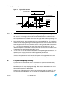
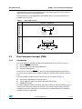
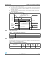
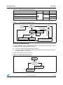
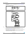
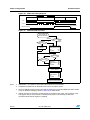
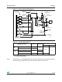
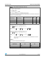
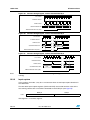
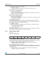
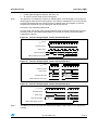
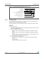
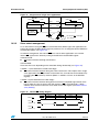
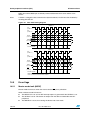
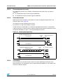
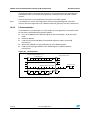
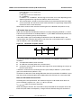
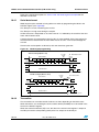
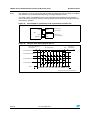
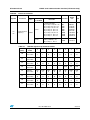
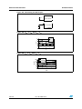
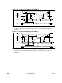
Figure 49. Counter timing diagram, internal clock divided by 2
CPU CLOCK
INTERNAL RESET
TIMER CLOCK
FFFD FFFE FFFF 0000
COUNTER REGISTER
0001
0002
0003
TIMER OVERFLOW FLAG (TOF)
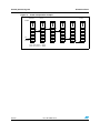
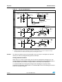
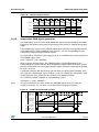
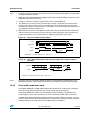
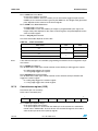
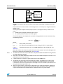
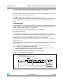
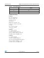
Figure 50. Counter timing diagram, internal clock divided by 4
CPU CLOCK
INTERNAL RESET
TIMER CLOCK
COUNTER REGISTER
FFFC
FFFD
0000
0001
TIMER OVERFLOW FLAG (TOF)
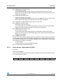
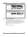
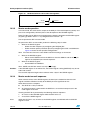
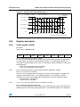
Figure 51. Counter timing diagram, internal clock divided by 8
CPU CLOCK
INTERNAL RESET
TIMER CLOCK
COUNTER REGISTER
FFFC
0000
FFFD
TIMER OVERFLOW FLAG (TOF)
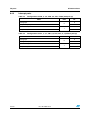
Note:
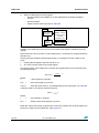
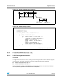
The MCU is in reset state when the internal reset signal is high, when it is low the MCU is
running.
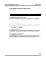
12.3.3
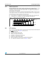
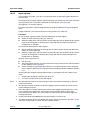
Input capture
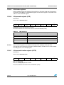
In this section, the index, i, may be 1 or 2 because there are two input capture functions in
the 16-bit timer.
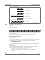
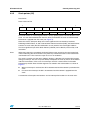
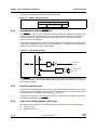
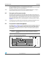
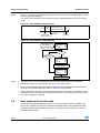
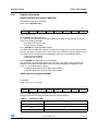
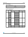
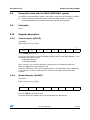
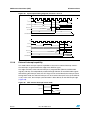
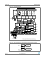
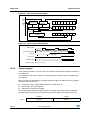
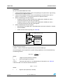
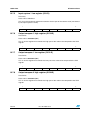
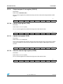
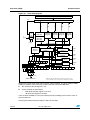
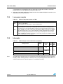
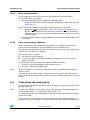
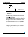
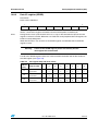
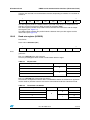
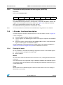
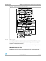
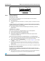
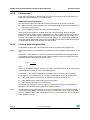
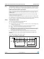
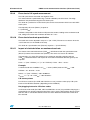
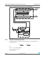
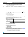
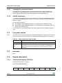
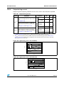
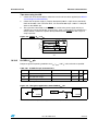
The two 16-bit input capture registers (IC1R and IC2R) are used to latch the value of the
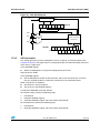
free running counter after a transition is detected on the ICAPi pin (see Figure 5).
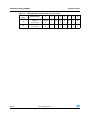
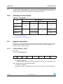
ICiR
MS Byte
LS Byte
ICiHR
ICiLR
ICiR register is a read-only register.
106/279
Doc ID 12468 Rev 3