1
Operating instructions
Diaphragm Motor-Driven Metering Pump
Sigma / 2 Basic Type S2Ba
P_SI_0074_SW
Please carefully read these operating instructions before use! · Do not discard!
The operator shall be liable for any damage caused by installation or operating errors!
Technical changes reserved.
Part no. 985908
Original operating instructions (2006/42/EC)
BA SI 063 01/14 EN
Supplemental instructions
Supplementary information
Read the following supplementary information in its entirety! Should you
already know this information, you will benefit more from referring to the
operating instructions.
The following are highlighted separately in the document:
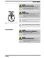
Fig. 1: Please read!
n
Enumerated lists
Operating guidelines
ð Outcome of the operating guidelines
- see (reference)
Information
This provides important information relating to the correct
operation of the unit or is intended to make your work easier.
Safety notes
Safety notes are identified by pictograms - see Safety Chapter.
Validity
These operating instructions conform to current EU regulations applicable
at the time of publication.
State the identity code and serial number
Please state identity code and serial number, which you can find on the
nameplate when you contact us or order spare parts. This enables the
device type and material versions to be clearly identified.
2
Table of contents
Table of contents
1
Identity code.................................................................................... 4
2
Safety chapter................................................................................. 6
3
Storage, transport and unpacking................................................. 11
4
Overview of equipment and control elements............................... 12
5
Functional description.................................................................... 14
5.1
5.2
5.3
5.4
Pump.....................................................................................
Liquid end..............................................................................
Integral relief valve................................................................
Multi-layer safety diaphragm.................................................
14
14
14
15
6
Assembly....................................................................................... 16
7
Installation, hydraulic..................................................................... 18
7.1 Basic installation notes.......................................................... 22
8
Installation, electrical..................................................................... 23
9
Start up.......................................................................................... 28
10
Maintenance.................................................................................. 31
11
Repairs.......................................................................................... 34
11.1 Cleaning valves................................................................... 35
11.2 Replacing the diaphragm.................................................... 36
12
Troubleshooting............................................................................. 40
13
Decommissioning.......................................................................... 43
14
Technical data............................................................................... 45
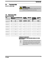
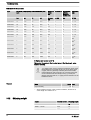
14.1 Performance data................................................................
14.2 Shipping weight...................................................................
14.3 Wetted materials.................................................................
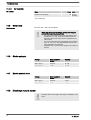
14.4 Ambient conditions..............................................................
14.4.1 Ambient temperatures......................................................
14.4.2 Media temperatures.........................................................
14.4.3 Air humidity......................................................................
14.5 Motor data...........................................................................
14.6 Stroke actuator....................................................................
14.7 Stroke control drive.............................................................
14.8 Diaphragm rupture sensor..................................................
14.9 Stroke sensor "Sigma"........................................................
14.10 Relay.................................................................................
14.11 Gear oil..............................................................................
14.12 Sound pressure level........................................................
14.13 Supplementary information for modified versions.............
45
46
47
47
47
47
48
48
48
48
48
49
50
50
50
50
15
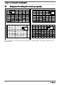
Diagrams for setting the metering capacity................................... 52
16
Dimensional drawings................................................................... 53
17
Motor data sheet standard motor.................................................. 56
18
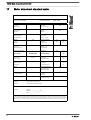
Liquid ends Sigma/ 2..................................................................... 57
19
Wear parts for Sigma/ 2................................................................. 61
19.1 Standard.............................................................................. 61
19.2 Physiological safety............................................................. 61
20
EC Declaration of Conformity for Machinery................................. 63
21
EC Declaration of Conformity for Machinery Used in Areas at
Risk of Explosion........................................................................... 64
3
Identity code
1
Identity code
S2Ba Sigma 2 Basic Type
H
Main power end, diaphragm
Type:
Capacity
____
__
Performance data at maximum back pressure and type: see nameplate on pump housing
Dosing head material
PV
PVDF
SS
Stainless steel
Seal material
T
PTFE seal
Displacement body
S
Multi-layer safety diaphragm with optical rupture indicator
A
Multi-layer safety diaphragm with diaphragm rupture signalling (contact)
H
Diaphragm for hygienic pump head
Dosing head design
0
no valve springs
1
with 2 valve springs, Hastelloy C; 0.1 bar
4 **
with relief valve, FPM seal, no valve spring
5 **
with relief valve, FPM seal, with valve springs
6 **
with relief valve, EPDM seal, no valve spring
7 **
with relief valve, EPDM seal, with valve springs
H
Hygienic pump head with tri-clamp connectors (max. 10 bar)
Hydraulic connector
0
Standard threaded connector (in line with technical data)
1
Union nut and PVC insert
2
Union nut and PP insert
3
Union nut and PVDF insert
4
Union nut and SS insert
7
Union nut and PVDF tube nozzle
8
Union nut and SS tube nozzle
9
Union nut and SS welding sleeve
Design
0
With ProMinent® logo (standard)
1
Without ProMinent® logo
F
Physiological safety with
regard to wetted mate‐
rials
FDA No. 21 CFR §177.1550
(PTFE)
Modified*
* order-related design, refer to
order paperwork for pump
features
M
Electric power supply
4
FDA No. 21 CFR §177.2510
(PVDF)
Identity code
S2Ba Sigma 2 Basic Type
_
Connection data - refer to nameplate on motor
1
No motor, with B14 flange, size 71 (DIN)
2
No motor, with C 42 flange (NEMA)
3
No motor, with B 5, size 56 (DIN)
Degree of protection
0
IP 55 (standard)
1
Exe design ATEX-T3
2
Exd version ATEX-T4
Stroke sensor
0
No stroke sensor (standard)
2
Pacing relay (reed relay)
3
Stroke sensor (Namur) for haz‐
ardous locations
Stroke length adjustment
0
Manual (standard)
1
With servomotor, 230 V,
50/60 Hz
2
With servomotor, 115 V,
50/60 Hz
3
With control motor 0...20 mA
230 V, 50/60 Hz
4
With control motor 4...20 mA
230 V, 50/60 Hz
5
With control motor 0...20 mA
115 V, 50/60 Hz
6
With control motor 4...20 mA
115 V, 50/60 Hz
FPM = fluorine rubber
** Standard with hose nozzle in the bypass Threaded connection on
request.
5
Safety chapter
2
Safety chapter
CAUTION!
These operating instructions include notes and quotes from
German guidelines relating to the system operator's scope of
responsibility. This information does not discharge the oper‐
ator from his responsibility as an operator and is intended
only to remind him or make him aware of specific problem
areas. This information does not lay claim to being complete,
nor applicable to every country and every type of application,
nor to being unconditionally up-to-date.
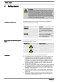
Identification of safety notes
Warning signs denoting different types of
danger
The following signal words are used in these operating instructions to
denote different severities of danger:
Signal word
Meaning
WARNING
Denotes a possibly dangerous sit‐
uation. If this is disregarded, you
are in a life-threatening situation
and this can result in serious inju‐
ries.
CAUTION
Denotes a possibly dangerous sit‐
uation. If this is disregarded, it
could result in slight or minor inju‐
ries or material damage.
The following warning signs are used in these operating instructions to
denote different types of danger:
Warning signs
Type of danger
Warning – high-voltage.
Warning – danger zone.
Intended use
n
n
n
n
n
6
Only use the pump to meter liquid metering chemicals.
In potentially explosive atmospheres in zone 1, device category II 2G,
explosion group II C, only operate the pump with the appropriate
nameplate (and the respective EC Declaration of Conformity) for
pumps for use in areas at risk of explosion in compliance with Direc‐
tive 94/9/EC in accordance with the European guidelines. The explo‐
sion group, category and degree of protection specified on the label
should correspond to or be better than the conditions given in the
intended field of application.
Only pumps with the identity code option "Multi-layer safety diaphragm
with visual rupture display" and "Multi-layer safety diaphragm with rup‐
ture signalling (contact)" are approved for use with flammable feed
chemicals, at back pressures of over 2 bar and if the operator takes
appropriate safety measures.
Only pumps with the design "F - Physiological safety with regard to
wetted materials" are approved for use with physiologically harmless
applications.
Only start up the pump after it has been correctly installed and com‐
missioned in accordance with the technical data and specifications
contained in the operating instructions.
Safety chapter
n
n
n
n
n
n
n
n
n
Qualification of personnel
Observe the general limitations with regard to viscosity limits, chem‐
ical resistance and density - see also ProMinent Resistance List (in
the Product Catalogue or at www.prominent.com/en/downloads)!
All other uses or modifications are prohibited.
Never operate pumps without the relevant nameplate (and the respec‐
tive EC Declaration of Conformity) for pumps for use in atmospheres
at risk from explosion in atmospheres potentially at risk from explo‐
sion.
The pump is not intended for the metering of gaseous media or solids.
The pump is not intended to meter explosive substances and mix‐
tures.
The pump is not intended for unprotected outside use.
The pump is only intended for industrial use.
The pump should only be operated by trained and authorised per‐
sonnel.
Observe the information contained in the operating instructions at the
different phases of the device's service life.
Action
Qualification
Storage, transport, unpacking
Instructed person
Assembly
Technical personnel, service
Planning hydraulic installation
Qualified personnel who have a
thorough knowledge of oscillating
diaphragm pumps.
Hydraulic installation
Technical personnel, service
Installation, electrical
Electrical technician
Operation
Instructed person
Maintenance, repair
Technical personnel, service
Decommissioning, disposal
Technical personnel, service
Troubleshooting
Technical personnel, electrical
technician, instructed person,
service
Explanation of the terms:
Technical personnel
A qualified employee is deemed to be a person who is able to assess the
tasks assigned to him and recognise possible dangers based on his/her
technical training, knowledge and experience, as well as knowledge of
pertinent regulations.
Note:
A qualification of equal validity to a technical qualification can also be
gained by several years employment in the relevant work area.
Electrical technician
Electrical technicians are deemed to be people, who are able to complete
work on electrical systems and recognise and avoid possible dangers
independently based on their technical training and experience, as well as
knowledge of pertinent standards and regulations.
Electrical technicians should be specifically trained for the working envi‐
ronment in which they are employed and know the relevant standards and
regulations.
Electrical technicians must comply with the provisions of the applicable
statutory directives on accident prevention.
Instructed person
7
Safety chapter
An instructed person is deemed to be a person who has been instructed
and, if required, trained in the tasks assigned to him/her and possible dan‐
gers that could result from improper behaviour, as well as having been
instructed in the required protective equipment and protective measures.
Service
Customer Service department refers to service technicians, who have
received proven training and have been authorised by ProMinent or Pro‐
Maqua to work on the system.
Safety notes
WARNING!
–
–
–
–
–
–
Observe the European Operator Directive 99/92/EC
(ATEX 137), implemented in Germany by the Industrial
Health and Safety Regulation and the German Ordi‐
nance on Hazardous Substances, for the installation and
operation of equipment in areas at risk from explosion.
Observe the European standards EN 1127-1, EN
60079-10, EN 60079-14, EN 60079-17 and EN
60079-25 and EN 50039 for inherently safe electrical cir‐
cuits. (In Germany these standards are partly imple‐
mented by VDE 0165 and VDE 0118).
Adhere to the respective national regulations outside of
the EU.
Ensure that installations in areas at risk from explosion
are checked by a "recognisably trained" skilled opera‐
tive. This applies specifically to intrinsically safe elec‐
trical circuits.
The following information relates essentially to the
unique characteristics in areas at risk from explosion but
does not replace the standard operating instructions.
Only clean plastic parts carefully with a damp cloth to
avoid electrostatic charges and sparks.
WARNING!
Warning of dangerous or unknown feed chemical
Should a dangerous or unknown feed chemical be used: It
may escape from the hydraulic components when working
on the pump.
–
–
Take appropriate protective measures before working on
the pump (e.g. safety glasses, safety gloves, ...).
Observe the safety data sheet for the feed chemical.
Drain and flush the liquid end before working on the
pump.
WARNING!
Danger from hazardous substances!
Possible consequence: Fatal or very serious injuries.
Please ensure when handling hazardous substances that
you have read the latest safety data sheets provided by the
manufacture of the hazardous substance. The actions
required are described in the safety data sheet. Check the
safety data sheet regularly and replace, if necessary, as the
hazard potential of a substance can be re-evaluated at any
time based on new findings.
The system operator is responsible for ensuring that these
safety data sheets are available and that they are kept up to
date, as well as for producing an associated hazard assess‐
ment for the workstations affected.
8
Safety chapter
CAUTION!
Warning of feed chemical spraying around
Feed chemical can spray out of the hydraulic components if
they are manipulated or opened due to pressure in the liquid
end and adjacent parts of the system.
–
–
Disconnect the pump from the mains power supply and
ensure that it cannot be switched on again by unauthor‐
ised persons.
Depressurise the system before commencing any work
on hydraulic parts.
CAUTION!
Warning of feed chemical spraying around
An unsuitable feed chemical can damage the parts of the
pump that come into contact with the chemical.
–
Take into account the resistance of the wetted materials
when selecting the feed chemical - see the ProMinent
product catalogue or visit www.prominent.com/en/down‐
loads.
CAUTION!
Danger of personnel injury and material damage
The use of untested third party parts can result in personnel
injuries and material damage.
–
Only fit parts to metering pumps, which have been
tested and recommended by ProMinent.
CAUTION!
Danger from incorrectly operated or inadequately maintained
pumps
Danger can arise from a poorly accessible pump due to
incorrect operation and poor maintenance.
–
–
Ensure that the pump is accessible at all times.
Adhere to the maintenance intervals.
Safety equipment
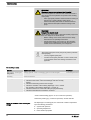
WARNING!
– Attach the following safety note to pumps that contain
parts made of electrically non-conductive plastic.
– Ensure that the label is always fitted and legible.
WARNING
Electrostatic charge may
cause an explosion!
Clean plastic parts very
carefully using a damp cloth!
Fig. 2
Isolating protective equipment
All isolating protective equipment must be installed for operation:
9
Safety chapter
n
n
n
Drive front cover
Motor fan cowling
Terminal box cover, motor
Only remove them when the operating instructions request you to do so.
Information in the event of an emergency
In the event of an electrical accident, disconnect the mains cable from the
mains or press the emergency cut-off switch fitted on the side of the
system!
If feed chemical escapes, also depressurise the hydraulic system around
the pump as necessary. Adhere to the safety data sheet for the feed
chemical.
Safety information relating to the operating
instructions
Prior to commissioning the system or system component, the system oper‐
ator is obliged to obtain the latest safety data sheet from the supplier for
the chemicals / resources to be used with the system. The operator should
create the legal framework for safe operation of the system or system
component, such as for example the preparation of operating instructions
(operator duties), based on the information provided in the data sheets
concerning health and safety, water and environmental protection and
taking into consideration the actual operating environment on site.
Sound pressure level
Sound pressure level LpA < 70 dB according to EN ISO 20361
at maximum stroke length, maximum stroke rate, maximum back pressure
(water)
10
Storage, transport and unpacking
3
Storage, transport and unpacking
Safety notes
WARNING!
Only return the metering pump for repair in a cleaned state
and with a flushed liquid end - refer to the chapter "Decom‐
missioning"!
Only return metering pumps with a completed Decontamina‐
tion Declaration form. The Decontamination Declaration con‐
stitutes an integral part of an inspection / repair order. A unit
can only be inspected or repaired when a Declaration of
Decontamination Form is submitted that has been completed
correctly and in full by an authorised and qualified person on
behalf of the pump operator.
The "Decontamination Declaration Form" can be found at
www.prominent.com/en/downloads.
WARNING!
Slings can tear
ProMinent only supplies non-reusable slings. These can tear
with repeated use.
–
Only use the slings once.
CAUTION!
Danger of material damage
The device can be damaged by incorrect or improper storage
or transportation!
–
–
–
–
The unit should only be stored or transported in a well
packaged state - preferably in its original packaging.
Only transport the unit when the red gear bleeding plug
is pushed in.
The packaged unit should also only be stored or trans‐
ported in accordance with the stipulated storage condi‐
tions.
The packaged unit should be protected from moisture
and the ingress of chemicals.
Scope of supply
Compare the delivery note with the scope of supply:
Storage
Personnel:
n
Technical personnel
1.
Plug the caps on the valves.
2.
Check if the red gear bleeding plug is pushed in.
3.
Preferably place the pump standing vertically on a pallet and secure
against falling over.
4.
Cover the pump with a tarpaulin cover - allowing rear ventilation.
Store the pump in a dry, sealed place under the ambient conditions
according to chapter "Technical Data".
11
Overview of equipment and control elements
4
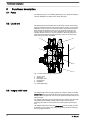
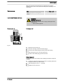
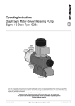
Overview of equipment and control elements
1
2
4
3
5
P_SI_0068_SW
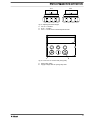
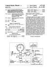
Fig. 3: Overview of equipment and control elements S2Ba
1
2
3
4
5
Drive motor
Drive unit
Stroke length adjustment knob
Liquid end with relief valve
Diaphragm rupture sensor
1
2
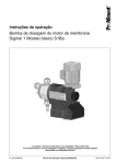
P_SI_0088_SW
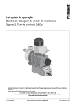
Fig. 4: Sigma control elements
1
2
12
Relief valve
Diaphragm rupture sensor (visual)
Overview of equipment and control elements
75%
0
50
25
75
20
30%
0
0
25
5
5
0
10
P_SI_0095_SW
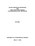
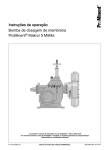
Fig. 5: Adjusting the stroke length
n
n
n
100 % = 4 rotations
25 % = 1 rotation
0.5 % = 1 scale mark on stroke adjustment dial
PG9
PG11
1
2
3
P_SI_0036
A
B
Fig. 6: Front cover for version with pacing relay
A
B
Pacing relay cable
Supply voltage cable for pacing relay PCB
13
Functional description
5
Functional description
5.1 Pump
The metering pump is an oscillating diaphragm pump, the stroke length of
which is adjustable. An electric motor drives the pump.
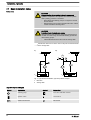
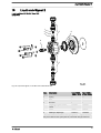
5.2 Liquid end
The diaphragm (2) hermetically shuts off the pump volume of the dosing
head (4) towards the outside. The suction valve (1) closes as soon as the
diaphragm (2) is moved in to the dosing head (4) and the feed chemical
flows through the discharge valve (3) out of the dosing head. The dis‐
charge valve (3) closes as soon as the diaphragm (2) is moved in the
opposite direction due to the vacuum pressure in the dosing head and
fresh feed chemical flows through the suction valve (1) into the dosing
head. One cycle is thus completed.
3
4
5
13
2
1
Fig. 7: Cross-section through the liquid end
1
2
3
4
5
13
Suction valve
Diaphragm
Discharge valve
Dosing head
Backplate
Safety diaphragm
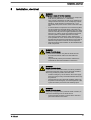
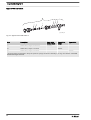
5.3 Integral relief valve
The integral relief valve normally operates as a simple, directly controlled
bleeder valve. The feed chemical then flows out through the hose connec‐
tion, e.g. into a storage tank, as soon as the pressure exceeds the pre-set
pressure value.
The integral relief valve can only protect the motor and the gear, and then
only against impermissible positive pressure that is caused by the
metering pump itself. It cannot protect the system against positive pres‐
sure.
The integral relief valve works as a bleed valve if the rotary dial is turned
clockwise up to the "open" stop, acting as a priming aid when starting up
the pump against pressure.
14
Functional description
1
2
3
4
5
P_SI_0019
Fig. 8: Integral relief valve
1
2
3
4
5
Spring, large
Ball
Rotary dial
Spring, small
Hose connection
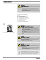
5.4 Multi-layer safety diaphragm
With visual diaphragm rupture sensors, in the event of a diaphragm rup‐
ture, the lowered red cylinder (6) springs forward beneath the transparent
cover (7) so that it then becomes clearly visible - see Fig. 9.
With the electrical diaphragm rupture sensor, a switch is switched. A sig‐
nalling device must be connected to signal the diaphragm rupture.
Fig. 9: Visual diaphragm rupture sensor, triggered and untriggered
15
Assembly
6
Assembly
Compare the dimensions on the dimension sheet and pump.
Base
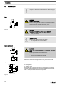
WARNING!
Danger of electric shock
If water or other electrically conducting liquids penetrate into
the drive housing, in any other manner than via the pump's
suction connection, an electric shock may occur.
–
h
Position the pump so that it cannot be flooded.
P_MOZ_0016_SW
Fig. 10
WARNING!
The pump can break through the base or slide off it
– Ensure that the base is horizontal, smooth and perma‐
nently load-bearing.
Capacity too low
Vibrations can disrupt the liquid end valves.
–
The supporting floor must not vibrate.
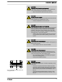
Space requirement
CAUTION!
Danger from incorrectly operated or inadequately maintained
pumps
Danger can arise from a poorly accessible pump due to
incorrect operation and poor maintenance.
A
–
–
A
Ensure that the pump is accessible at all times.
Adhere to the maintenance intervals.
Position the pump so that control elements such as the stroke length
adjustment knob or the indicating dial A are easily accessible.
P_MOZ_0018_SW
Fig. 11
f
1
2
f
f
3
P_MOZ_0017_SW
Fig. 12
16
1
2
3
Discharge valve
Dosing head
Suction valve
Ensure that there is sufficient free space (f) around the dosing head, as
well as the suction and discharge valve, so that maintenance and repair
work can easily be carried out on these components.
Assembly
Liquid end alignment
Capacity too low
The liquid end valves cannot close correctly if they are not
upright.
–
Ensure that the discharge valve is upright.
Fastening
Capacity too low
Vibrations can disrupt the liquid end valves.
–
m
DN
Secure the metering pump so that no vibrations can
occur.
Take the dimensions (m) for the fastening holes from the appropriate
dimensional drawings or data sheets.
Fix the pump base to the base with suitable screws.
m
P_MOZ_0015_SW
Fig. 13
17
Installation, hydraulic
7
Installation, hydraulic
WARNING!
EX pumps in areas at risk from explosion
– It is essential that metering pumps to be used in areas at
risk from explosion are fitted with an appropriate safety
relief valve on the outlet side of the metering pump (to
protect it from excessive heating up from overloading
and from impact sparks resulting from overloading trig‐
gered by the breakage of drive parts).
– In the event of different temperature classes with the
various components, the possible uses of the complete
pump are based on the component with the lowest tem‐
perature class.
– Diaphragm pump with mechanically actuated diaphragm,
e.g. MTMa.., TZMa.., Sigmas S1Ba...., S2BaHM...,
S3Ba: no additional action is required, but in principle
use the design with Ex"i" diaphragm rupture indicator.
– Ensure that installations in areas at risk from explosion
are checked by a "recognisably qualified and skilled"
operative.
– Please observe the relevant national regulations and
guidelines during installation!
WARNING!
Danger of fire with flammable feed chemicals
– Combustible media may only be transported using stain‐
less steel dosing heads. In exceptional cases where this
is not possible, PTFE with carbon can be used, whereby
our TT_ versions are manufactured from this conducting
plastic. Here, the operator is urged to take special care
due to the low mechanical strength.
– Only designs of metering pump with Ex"i" diaphragm
rupture indicators are permitted in principle to meter
flammable media.
– The following applies to all metering pumps for the
metering of combustible media:
During filling and draining of the liquid end, an expert
must ensure that feed chemical does not come into con‐
tact with oxygen.
WARNING!
Warning of feed chemical reactions to water
Feed chemicals that should not come into contact with water
may react to residual water in the liquid end that may origi‐
nate from works testing.
–
–
Blow the liquid end dry with compressed air through the
suction connector.
Then flush the liquid end with a suitable medium through
the suction connector.
WARNING!
The following measures are an advantage when working with
highly aggressive or hazardous feed chemicals:
–
–
18
Install a bleed valve with recirculation in the storage
tank.
Install an additional shut-off valve on the discharge or
suction ends.
Installation, hydraulic
CAUTION!
Warning of feed chemical spraying around
PTFE seals, which have already been used / compressed,
can no longer reliably seal a hydraulic connection.
–
New, unused PTFE seals must always be used.
CAUTION!
Suction problems possible
The valves may no longer close properly with feed chemicals
with a particle size of greater than 0.3 mm.
–
Install a suitable filter in the suction line.
CAUTION!
Warning against the discharge line bursting
With a closed discharge line (e.g. due to a clogged discharge
line or by closing a valve), the pressure that the metering
pump generates can reach several times the permissible
pressure of the system or the metering pump. This could
lead to lines bursting, resulting in dangerous consequences
with aggressive or toxic feed chemicals.
–
Install a relief valve that limits the pressure of the pump
to the maximum permissible operating pressure of the
system.
CAUTION!
Uncontrolled flow of feed chemical
Feed chemicals can leak through a stopped metering pump if
there is back pressure.
–
Use an injection valve or a vacuum breaker.
CAUTION!
Uncontrolled flow of feed chemical
Feed chemical can leak through the metering pump in an
uncontrolled manner in the event of excessive priming pres‐
sure on the suction side of the metering pump.
–
–
Do not exceed the maximum permissible priming pres‐
sure for the metering pump.
Arrange the installation properly.
CAUTION!
Warning against leaks
Leaks can occur on the pump connection depending on the
insert used.
–
P_SI_0021
Fig. 14: Moulded composite seals with
corrugated insert
–
The pump is supplied with PTFE moulded composite
seals with a flare, which are used for the pump connec‐
tions. They seal the connections between grooved pump
valves and the grooved inserts from ProMinent - see
Fig. 14.
In the event that an unflared insert is used (e.g. third
party part), an elastomer flat seal must be used - see
Fig. 15.
19
Installation, hydraulic
CAUTION!
Warning of backflow
Liquid ends, foot valves, back pressure valves, relief valves
or spring-loaded injection valves do not constitute absolutely
leak-tight sealing elements.
P_SI_0022
–
Use a shut-off valve, a solenoid valve or a vacuum
breaker for this purpose.
Fig. 15: Elastomer flat seal for a smooth
insert
Integral relief valve
WARNING!
Product can be dangerously contaminated
Only with the design "Physiologically safety with regard to
wetted materials".
If the integral bleed valve or the integral relief valve opens,
the feed chemical comes into contact with physiologically
harmful seals.
–
Do not route feed chemical that escapes from the inte‐
gral bleed valve or the integral relief valve back into the
process.
CAUTION!
Danger due to incorrect use of the integral relief valve
The integral relief valve can only protect the motor and the
gear, and then only against impermissible positive pressure
that is caused by the metering pump itself. It cannot protect
the system against positive pressure.
–
–
Protect the motor and gear of the system against posi‐
tive pressure using other mechanisms.
Protect the system against illegal positive pressure using
other mechanisms.
CAUTION!
Warning of feed chemical spraying around
If no relief valve was connected to the overflow line, the feed
chemical sprays out of the hose connection as soon as the
relief valve opens.
–
An overflow line must always be connected to the inte‐
gral relief valve and be fed back to the storage tank or if required by the regulations - into a special storage
tank.
CAUTION!
Danger of cracking
Cracking of the PVT liquid end can occur if a metal overflow
line is connected to the relief valve.
–
20
Never connect a metal overflow line to the relief valve.
Installation, hydraulic
CAUTION!
Danger of the integral relief valve failing
The integral relief valve no longer operates reliably with feed
chemicals having a viscosity of greater than 200 mPa s.
–
Only use the integral relief valve with feed chemicals
having a viscosity up to 200 mPa s.
CAUTION!
Warning against leaks
Feed chemical which remains in the overflow line at the relief
valve, can attack the valve or cause it to leak
–
Route the overflow line with a continuous slope and
moreover with the tube nozzle pointed downwards - see
Fig. 16.
If the overflow line is fed into the suction line, the bleed func‐
tion is blocked.
P_SI_0023
Fig. 16: Permissible alignment of the relief
valve
Therefore lead the overflow line back into the storage tank.
When operating the integral relief valve close to the opening
pressure, a minimal overflow into the overflow line can occur.
Diaphragm rupture sensor
CAUTION!
Danger resulting from unnoticed diaphragm rupture
If the pump has been ordered with an electric diaphragm rup‐
ture sensor, it still has to be installed.
–
Screw the enclosed diaphragm rupture sensor into the
liquid end.
CAUTION!
Warning of unnoticed diaphragm rupture
Only above approximately 2 bar system back pressure is a
signal generated upon a diaphragm rupture.
–
Only rely on the diaphragm rupture sensor at back pres‐
sures greater than 2 bar.
21
Installation, hydraulic
7.1 Basic installation notes
Safety notes
CAUTION!
Danger resulting from rupturing hydraulic components
Hydraulic components can rupture if the maximum permis‐
sible operating pressure is exceeded.
–
–
Never allow the metering pump to run against a closed
shut-off device.
With metering pumps without integral relief valve: Install
a relief valve in the discharge line.
CAUTION!
Hazardous feed chemicals can escape
With hazardous feed chemicals: Hazardous feed chemical
can leak out when using conventional bleeding procedures
with metering pumps.
–
Install a bleed line with a return into the storage tank.
Shorten the return line so that it does not dip into the feed chemical
in the storage tank.
A)
B)
1
1
PD
*
2
2
P_MOZ_0043_SW
Fig. 17: (A) standard installation, (B) with pulsation damper
1
2
Main line
Storage tank
Legend for hydraulic diagram
Symbol
22
Explanation
Symbol
Explanation
Metering pump
Foot valve with filter meshes
Injection valve
Level switch
Multifunctional valve
Manometer
Installation, electrical
8
Installation, electrical
WARNING!
EX pumps in areas at risk from explosion
– Potential-free switches can be evaluated as simple elec‐
trical devices (EN 60079-14 or EN 50020).
– Only connect potential-free as well as non-isolating low
voltage switch accessories, such as diaphragm rupture
indicators, stroke frequency instruments etc., to an
intrinsically safe power circuit in areas at risk from explo‐
sion.
– If several electrical components are connected together,
test and confirm the technical safety of the entire con‐
nected system. This can either be in the form of a decla‐
ration of conformity from the supplier (ProMinent) for the
entire unit or, with the supply of individual components,
with the operator's explosion protection document.
– Only motor protection switches, mains switches and
fuses permitted for use in areas at risk from explosion in
line with the manufacturer's information may be used as
electrical components in areas at risk from explosion.
– Note the enclosed documentation for the individual elec‐
trical components.
WARNING!
Danger of electric shock
Unprofessional installation may lead to electric shocks.
–
–
Provide all shortened cable cores with cable end
sleeves.
Only technically trained personnel are authorised to
undertake the electrical installation of the device.
WARNING!
Danger of electric shock
In the event of an electrical accident, it must be possible to
quickly disconnect the pump, and any electrical ancillaries
which may possibly be present, from the mains.
–
–
Install an emergency cut-off switch in the mains supply
line to the pump and any electrical ancillaries which may
be present or
Integrate the pump and electrical ancillaries which may
be present in the emergency cut-off management of the
system and inform personnel of the isolating option.
WARNING!
Danger of electric shock
This pump is equipped with a protective earth conductor, to
reduce the risk arising from an electric shock.
–
Connect the PE conductor to "earth" with a clean and
permanent electrical connection.
23
Installation, electrical
WARNING!
Danger of electric shock
A mains voltage may exist inside the motor or electrical ancil‐
laries.
–
If the housing of the motor or electrical ancillaries has
been damaged, you must disconnect it from the mains
immediately. The pump must only be returned to service
after an authorised repair.
What requires electrical installation?
n
n
n
n
n
n
n
n
Motor
External fan (optional)
Stroke control drive (optional)
Stroke adjusting drive (optional)
Diaphragm rupture sensor (Option)
Stroke sensor (optional)
Pacing relay (option)
Frequency converter (optional)
Motor
P_SI_0012_SW
Fig. 18: Direction of rotation of motor
WARNING!
EX pumps in areas at risk from explosion
– Protect drive motors with appropriate motor protection
switches. Only use motor protection permitted for this
kind of application with Ex"e" motors. (Protection against
heating from overloading)
– Ensure that motors are only installed and inspected by a
"recognisably trained" skilled operative in areas at risk
from explosion.
– Observe the enclosed operating instructions for the Ex
motor.
CAUTION!
The motor can be damaged
Provide appropriate motor protection devices (e.g. motor pro‐
tection switch with thermal overcurrent trip) to protect the
motor against overloading.
Fuses do not provide motor protection.
CAUTION!
The pump can be damaged
The pump can be damaged if the motor drives the pump in
the wrong direction.
–
When connecting the motor, pay attention to the correct
direction of rotation indicated by the arrow on the fan
cover, as shown in Fig. 18.
Install an electrical isolating device in the mains supply
cable, e.g. a mains switch, to be able to switch off the pump
independently of the entire installation (e.g. for repair).
24
Installation, electrical
1.
Install a motor protection switch, as the motors have no fuse.
2.
Install an emergency cut-off switch or include the motor in the emer‐
gency cut-off management plan for the system.
3.
Only connect the motor to the voltage supply using a suitable cable.
–
–
Key motor data can be found on the nameplate.
The terminal wiring diagram is located in the terminal
box.
Motor data sheets, special motors, special motor flanges,
external fan, temperature monitoring
– For further information for the motor with identity code
specification "S", refer to the motor data sheet in the
Appendix. Motor data sheets can be requested for all
other motors.
– For motors other than those with identity code specifica‐
tions "S", "M" or "N": Pay special attention to the oper‐
ating instructions for the motors.
– Special motors or special motor flanges are possible on
request.
External fans
CAUTION!
Provide a separate power supply for the external fan with
motors with external fans (identity code specification "R" or
"Z").
Variable speed motors with frequency
converter
Connect up the motor as per the wiring diagram for the controller, if it is
controlled by an electronic control unit (such as direct current motors by a
frequency converter).
Stroke length actuators / control drives
Connect the motors as per the enclosed wiring diagram or the wiring dia‐
gram on the inside of the housing.
CAUTION!
Only operate stroke length actuators / control drives when
the pump is running!
Otherwise they will be damaged.
Diaphragm rupture sensor (Option)
WARNING!
Risk of electric shock
In event of a defect, there is a risk of electric shock when
conductive feed chemical are used.
–
For safety reasons we recommend connecting to a pro‐
tective low voltage, e.g. in accordance with EN 60335-1
(SELV ).
25
Installation, electrical
CAUTION!
Danger resulting from unnoticed diaphragm rupture
If the pump has been ordered with an electric diaphragm rup‐
ture sensor, it must also be electrically installed.
–
Install the enclosed diaphragm rupture sensor electri‐
cally to a suitable monitoring device.
a) Diaphragm rupture sensor with switch contact
–
The cable can be poled as required.
b) Namur sensor, inherently safe
The monitor / power supply installed by the customer must be able to eval‐
uate the current variations of the Namur sensor for indicating a diaphragm
rupture!
Stroke sensor (identity code specification
"Stroke sensor": 3)
Connect the stroke sensor to a suitable monitoring device according
to the technical data provided with the monitoring device and that of
the stroke sensor - see chapter "Technical data".
Pacing relay (identity code specification
"Stroke sensor": 2)
1.
Install the cable which originates from the pacing relay - see the
figure in the chapter entitled "Overview of equipment and control
elements": Cable A, left.
The cable polarity is unimportant.
2.
Install the power supply cable to the pacing relay PCB - see the
figure in the chapter entitled "Overview of equipment and control
elements": Cable B, right.
CAUTION!
Warning of overload
If the current through the relay becomes too high, it
can be destroyed by heating.
–
Fit a circuit breaker.
Pacing relay terminal output data
Data
Maximum voltage
24 VDC
Maximum current
100 mA
Closing duration, approx.
100 ms
Service life *
26
Value Unit
50 x 106 (10 V, Play
10 mA)
Installation, electrical
* at rated load
The contacts are potential-free.
The pacing relay is a N/O as standard.
Supply voltage for pacing relay PCB
Available supply vol‐
tages
Mains supply fre‐
quency
Power consumption
230 V AC (180-254 V)
50 / 60 Hz
10 mA (at 230 V, 50 Hz)
115 V AC (90-134 V)
50 / 60 Hz
15 mA (at 115 V, 60 Hz)
24 V DC (20-28 V)
-
10 mA (at 24 V DC)
Heating cartridge
Install the heating cartridge according to its documentation. It must
only be connected to the supplied power supply!
Other units
Install the other units in line with their documentation.
27
Start up
9
Start up
Safety notes
WARNING!
EX pumps in areas at risk from explosion
– An appropriately skilled operative should check whether
the appropriate installation information from the "Installa‐
tion " chapter has been implemented correctly.
WARNING!
Fire hazard with flammable media
Only with combustible media: These may start to burn when
combined with oxygen.
–
During filling and draining of the liquid end, an expert
must ensure that feed chemical does not come into con‐
tact with oxygen.
CAUTION!
Feed chemical could escape
– Check suction and discharge lines and liquid end with
valves for leak-tightness and tighten if necessary.
– Check whether the necessary flushing pipes or bleed
lines have been connected.
CAUTION!
Prior to commissioning, check that the power end motor and
corresponding ancillary equipment is connected in compli‐
ance with the regulations.
CAUTION!
When using pumps with speed control, observe the instruc‐
tions in the frequency converter operating instructions.
Diaphragm rupture sensor
CAUTION!
Danger resulting from unnoticed diaphragm rupture
If the pump has been ordered with an electric diaphragm rup‐
ture sensor, it still has to be installed.
–
Screw the enclosed diaphragm rupture sensor into the
liquid end.
CAUTION!
Warning of unnoticed diaphragm rupture
Only above approximately 2 bar system back pressure is a
signal generated upon a diaphragm rupture.
–
28
Only rely on the diaphragm rupture sensor at back pres‐
sures greater than 2 bar.
Start up
CAUTION!
Possible environmental and material damage
In event the red gear bleeding plug is sealed, during opera‐
tion it prevents any pressure compensation between the
drive housing and the surroundings. This ensure that oil can
be pushed from the drive housing.
–
Remove the gear bleeding plug before commissioning.
Remove the gearbox vent stopper
Before start up pull the red gearbox vent stopper off, see chapter "Over‐
view of equipment and control elements".
Checking the oil level
When the pump is idle, check whether the oil level in the pump is in the
middle of the oil level indicator.
This will rule out the pump losing oil and suffering damage.
Checking the direction of rotation
When commissioning the unit, check whether the drive motor is rotating
correctly - check this against the arrow on the motor housing or the dia‐
gram in the chapter entitled "Electrical Installation."
Using the integral relief valve
CAUTION!
Danger due to incorrect use of the integral relief valve
The integral relief valve can only protect the motor and the
gear, and then only against impermissible positive pressure
that is caused by the metering pump itself. It cannot protect
the system against positive pressure.
–
–
Protect the motor and gear of the system against posi‐
tive pressure using other mechanisms.
Protect the system against illegal positive pressure using
other mechanisms.
CAUTION!
Danger of the integral relief valve failing
The integral relief valve no longer operates reliably with feed
chemicals having a viscosity of greater than 200 mPa s.
–
Priming against pressure
Only use the integral relief valve with feed chemicals
having a viscosity up to 200 mPa s.
1.
Hydraulically isolate the discharge line from the pump using an iso‐
lation device.
2.
Turn the rotary dial on the integral relief valve in a counter-clockwise
direction as far as the "open" stop.
ð The excess pressure escapes through the hose connector.
3.
Run the pump until the feed chemical coming out of the hose con‐
nector is free from bubbles.
4.
Turn the rotary dial on the integral relief valve in a clockwise direc‐
tion up to the "close" stop.
ð The pump can be started.
29
Start up
When operating the integral relief valve close to the opening
pressure, a minimal overflow into the overflow line can occur.
Adjusting the stroke length
Only adjust the stroke length when the pump is running. This
is easier and also better for the pump.
75%
0
50
25
75
20
30%
0
0
25
5
0
5
10
P_SI_0095_SW
Fig. 19: Adjusting the stroke length
n
n
n
30
100 % = 4 rotations
25 % = 1 rotation
0.5 % = 1 scale mark on stroke adjustment dial
Maintenance
10
Maintenance
Safety notes
WARNING!
EX pumps in areas at risk from explosion
– Ensure correct operation in general, particularly of the
power end and bearing, by regular monitoring (for leaks,
noises, temperatures, smell ...).
– Do not allow the pump to become hot due to a lack of oil.
Regularly check lubricated metering pumps for the exis‐
tence of lubricant, for example by checking the liquid
level, visual leak control etc. If oil is leaking, examine the
leakage point immediately and eliminate the cause.
– Check the correct operation of the relief valve down‐
stream of the pump. In premises at risk from explosion,
the relief valve should prevent the gear from becoming
overloaded and becoming hot.
– When cleaning plastic components, ensure that no elec‐
trostatic charges are generated by excessive friction. see warning label.
– Replace wear parts, such as bearings, as soon as unac‐
ceptable wear is detected. (The nominal service life
cannot be calculated with lubricated bearings).
– Use genuine spare parts for replacement.
– Only perform tests and repairs in compliance with DIN
EN IEC 60079-17 and only permit "experienced per‐
sonnel who have the requisite knowledge" to perform the
work.
– These measures constitute the minimum protective
measurements stipulated by ProMinent. It is the duty of
the operator to eliminate any other dangers identified by
appropriate measures.
WARNING!
Fire hazard with flammable media
Only with combustible media: These may start to burn when
combined with oxygen.
–
During filling and draining of the liquid end, an expert
must ensure that feed chemical does not come into con‐
tact with oxygen.
WARNING!
It is mandatory that you read the safety information and
specifications in the "Storage, Transport and Unpacking"
chapter prior to shipping the pump.
CAUTION!
Warning of feed chemical spraying around
Feed chemical can spray out of the hydraulic components if
they are manipulated or opened due to pressure in the liquid
end and adjacent parts of the system.
–
–
Disconnect the pump from the mains power supply and
ensure that it cannot be switched on again by unauthor‐
ised persons.
Depressurise the system before commencing any work
on hydraulic parts.
31
Maintenance
WARNING!
Warning of dangerous or unknown feed chemical
Should a dangerous or unknown feed chemical be used: It
may escape from the hydraulic components when working
on the pump.
–
–
Take appropriate protective measures before working on
the pump (e.g. safety glasses, safety gloves, ...).
Observe the safety data sheet for the feed chemical.
Drain and flush the liquid end before working on the
pump.
WARNING!
Danger of an electric shock
When working on the motor or electrical auxiliary equipment,
there is a danger of an electric shock.
–
–
Before working on the motor, take note of the safety
instructions in its operating instructions!
Should external fans, servomotors or other auxiliary
equipment be installed, these should also be discon‐
nected and checked that they are voltage free.
Third party spare parts for the pumps may lead to problems
when pumping.
–
–
Use only original spare parts.
Use the correct spare parts kits. In case of doubt, refer
to the exploded views and ordering information in the
appendix.
Standard liquid ends:
Interval
Maintenance work
Personnel
After approx. 5,000 oper‐
ating hours
Change gear oil - refer to "Changing gear oil" in this chapter.
Instructed personnel
Quarterly
Check the oil level.
Quarterly*
n
n
n
n
n
n
Check that the metering lines are fixed firmly to the liquid end.
Check that the suction valve and discharge valve are correctly
seated.
Check that the dosing head screws are tight.
Check the condition of the metering diaphragm - see Ä ‘Check
the condition of the metering diaphragm’ on page 32.
Check that the flow is correct: Allow the pump to prime briefly.
Check that the electrical connections are intact.
Technical personnel
* Under normal loading (approx. 30 % of continuous operation).
Under heavy loading (e.g. continuous operation): shorter intervals.
Check the condition of the metering dia‐
phragm
The diaphragm is a wearing part, the service life of which is dependent
upon the following parameters:
n
n
n
32
System back pressure
Operating temperature
Feed chemical properties
Maintenance
When using abrasive feed chemicals, the diaphragm service life is
reduced. In such cases, more frequent checking of the diaphragm is rec‐
ommended.
Tightening torques
Data
Value Unit
Tightening torques for dosing head
screws:
4.5 ... 5.0 Nm
Liquid ends with integral relief valve
WARNING!
Warning of eye injuries
When opening the relief valve, a spring under high tension
can jump out.
–
Wear protective glasses.
Draining gear oil
Changing gear oil
1
3
2
P_SI_0143_SW
Fig. 20
1.
Remove the vent screw (1).
2.
Place an oil trough under the oil drain plug (2).
3.
Unscrew the oil drain plug (2) from the power end housing.
4.
Allow the gear oil to run out of the power end.
5.
Screw in the oil drain plug (2) with a new seal.
Filling with gear oil
Prerequisites: Gear oil according to the "Ordering information" chapter is
available.
1.
Slowly pour gear oil through the vent screw (1) opening until the oil
inspection window (3) is half covered.
2.
Allow the pump to run for 1... 2 minutes
3.
Replace the vent screw (1).
33
Repairs
11
Repairs
Safety notes
WARNING!
EX pumps in areas at risk from explosion
– Generally check the proper operation of the system, par‐
ticularly of the power end and bearings, by regular moni‐
toring (for leaks, noises, temperatures, smell .... ).
WARNING!
Fire hazard with flammable media
Only with combustible media: These may start to burn when
combined with oxygen.
–
During filling and draining of the liquid end, an expert
must ensure that feed chemical does not come into con‐
tact with oxygen.
WARNING!
It is mandatory that you read the safety information and
specifications in the "Storage, Transport and Unpacking"
chapter prior to shipping the pump.
CAUTION!
Warning of feed chemical spraying around
Feed chemical can spray out of the hydraulic components if
they are manipulated or opened due to pressure in the liquid
end and adjacent parts of the system.
–
–
Disconnect the pump from the mains power supply and
ensure that it cannot be switched on again by unauthor‐
ised persons.
Depressurise the system before commencing any work
on hydraulic parts.
WARNING!
Warning of dangerous or unknown feed chemical
Should a dangerous or unknown feed chemical be used: It
may escape from the hydraulic components when working
on the pump.
–
–
34
Take appropriate protective measures before working on
the pump (e.g. safety glasses, safety gloves, ...).
Observe the safety data sheet for the feed chemical.
Drain and flush the liquid end before working on the
pump.
Repairs
11.1
Cleaning valves
Unsuitable spare parts for the valves may lead to problems
for the pumps.
–
–
Only use new components that are especially adapted to
fit your valve (both in terms of shape and chemical
resistance).
Use the correct spare parts kits. In case of doubt, refer
to the exploded views and ordering information in the
appendix.
Only with the "Physiologically safe" design:
WARNING!
Product can be dangerously contaminated
Only use the spare parts from the "Physiologically safe"
spare parts kits.
Personnel:
n
Technical personnel
Repairing ball valves
CAUTION!
Warning of personal injury and material damage
Feed chemical may escape from the liquid end, for example,
if ball valves not repaired correctly.
–
–
Only use new components which fit your valve - both in
terms of shape and chemical resistance!
Note the flow direction of the discharge and suction con‐
nectors when fitting the valve.
CAUTION!
Warning of feed chemical spraying around
PTFE seals, which have already been used / compressed,
can no longer reliably seal a hydraulic connection.
–
New, unused PTFE seals must always be used.
1
2
3
4
5
P_SI_0013_SW
Fig. 21: Simple cross-section through ball valve
1
2
3
4
5
Flat seal
Valve body
Valve ball
Valve seat
Valve cap
35
Repairs
11.2
Replacing the diaphragm
Third party spare parts for the pumps may lead to problems
when pumping.
–
–
Personnel:
Use only original spare parts.
Use the correct spare parts kits. In case of doubt, refer
to the exploded views and ordering information in the
appendix.
n
Technical personnel
Requirements:
n
n
n
If necessary take protective measures.
Adhere to the safety data sheet for the feed chemical.
Ensure that the system is at atmospheric pressure.
1.
Drain the liquid end: Place the liquid end on its head and allow the
feed chemical to run out; flush out with a suitable medium; flush the
liquid end thoroughly when using hazardous feed chemicals!
2.
With the pump running, move the stroke adjustment dial to the stop
at 0 % stroke length.
ð The drive axle is now difficult to turn.
3.
Switch off the pump.
4.
Unscrew the hydraulic connectors on the discharge and suction
side.
5.
Unscrew the diaphragm rupture sensor from the dosing head.
6.
Remove the 6 screws on the dosing head.
7.
Remove the dosing head.
8.
Check the condition of the diaphragm rupture sensor - see Ä ‘
9.
Loosen the diaphragm from the drive axle with a gentle backwards
turn in the anti-clockwise direction.
10.
Completely unscrew the diaphragm from the drive axle.
11.
Tentatively screw the new diaphragm anticlockwise up to the stop
on the drive axle.
Checking the condition of the diaphragm rupture sensor’
on page 38.
ð The diaphragm now is now seated against the stop of the
thread while the diaphragm flap is within the tolerance range.
36
Repairs
1
2
3
A
P_SI_0029
Fig. 22: Tolerance range of the flap on the backplate
1
2
3
A
12.
Diaphragm
Backplate
Flap
Tolerance range
Should this not work, remove dirt or swarf out of the thread and
screw the diaphragm correctly onto the drive axle this time.
ð If this is still unsuccessful, contact ProMinent-ProMaqua cus‐
tomer service.
13.
Place the dosing head with the screws onto the diaphragm - the
suction connector must be pointing downwards in the pump's fitting
position.
14.
Tighten the screws gently to start with.
15.
Screw the diaphragm rupture sensor into the dosing head.
16.
Start up the pump and adjust the stroke length to 100 %.
17.
Stop the pump and tighten the screws crosswise. Tightening torque
- see Ä ‘Tightening torques’ on page 33.
18.
Start the pump and at maximum pressure, check for leaks.
CAUTION!
Warning of escaping feed chemical
The liquid end may leak should it not be possible to check
the tightening torque of the screws.
–
–
Check the tightening torque of the screws after 24 hours
of operation!
With PP, PC and TT dosing heads also re-check the
tightening torques quarterly!
37
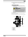
Repairs
Checking the condition of the diaphragm
rupture sensor
1.
If the inside of the diaphragm rupture sensor has become damp or
dirt has penetrated it: replace.
1
7
6
5
4
2
3
P_SI_0020_SW
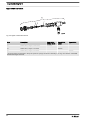
Fig. 23: Section through the Sigma diaphragm rupture warning system
("Visual break indicator" version)
1
2
3
4
5
6
7
Working layer (≙ operating diaphragm)
Safety layer (≙ safety diaphragm)
Flap
Piston
Diaphragm rupture sensor
Cylinder, red
Cover, transparent
2.
If the piston of the diaphragm rupture sensor - see Fig. 23, item 4 should have become dirty or damp, clean both it and the hole in
which it runs.
3.
Check whether it can move freely in the hole.
4.
Refit the clean diaphragm rupture sensor with the clean piston.
5.
Test the diaphragm rupture sensor.
Optical diaphragm rupture sensor
1.
Unscrew the transparent cover from the diaphragm rupture sensor.
2.
Press the red cylinder into the diaphragm rupture sensor until it
engages.
3.
Press the piston on the other side of the diaphragm rupture sensor
with a blunt, smooth object into the dosing head (approximately 4
mm) until it triggers.
CAUTION!
Feed chemical may escape
If the expandable flap of the diaphragm is damaged,
then feed chemical can escape when there is a dia‐
phragm rupture.
The piston must not be scratched, it must remain com‐
pletely smooth so that during operation it does not
damage the expandable flap of the diaphragm.
38
4.
Press the red cylinder into the diaphragm rupture sensor again and
repeat the test.
5.
If it does not trigger both times, replace the membrane rupture
sensor.
Repairs
6.
After a successful test, screw the transparent cover onto the dia‐
phragm rupture sensor and then continue at the top by fitting the
diaphragm.
Electrical diaphragm rupture sensor
1.
Press the piston of the diaphragm rupture sensor with a blunt,
smooth object into the dosing head (approximately 4 mm) until the
monitor triggers alarm.
CAUTION!
Feed chemical may escape
If the expandable flap of the diaphragm is damaged,
then feed chemical can escape when there is a dia‐
phragm rupture.
The piston must not be scratched, it must remain com‐
pletely smooth so that during operation it does not
damage the expandable flap of the diaphragm.
2.
Repeat the test.
3.
If the monitor does not trigger an alarm both times, replace the
membrane rupture sensor.
4.
After a successful test, continue at the top by fitting the diaphragm.
5
3
13
4
2
1
P_SI_0038
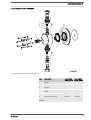
Fig. 24: Cross-section through the liquid end
1
2
3
4
5
13
Suction valve
Diaphragm
Discharge valve
Dosing head
Backplate
Safety diaphragm
39
Troubleshooting
12
Troubleshooting
Safety notes
WARNING!
EX pumps in areas at risk from explosion
– Ensure correct operation in general (no leaks, unusual
noises, high temperatures, unusual smells etc.), particu‐
larly of the power end and bearings.
– Do not allow the pump to become hot due to a lack of oil!
If oil is escaping, investigate the leak immediately and
eliminate the cause.
– When cleaning plastic parts, ensure that excessive fric‐
tion does not cause electrical charges - see warning
label.
– Replace wear parts, such as bearings, as soon as unac‐
ceptable wear is detected. (The nominal service life
cannot be calculated with lubricated bearings).
– Use genuine spare parts for replacement.
– Only perform tests and repairs in compliance with DIN
EN IEC 60079-17 and only permit "experienced per‐
sonnel who have the requisite knowledge" to perform the
work.
WARNING!
Fire hazard with flammable media
Only with combustible media: These may start to burn when
combined with oxygen.
–
During filling and draining of the liquid end, an expert
must ensure that feed chemical does not come into con‐
tact with oxygen.
WARNING!
Danger of an electric shock
Personnel working on electrical parts can be electrocuted if
all electrical lines carrying current have not been discon‐
nected.
–
–
–
Disconnect the supply cable before working on the motor
and prevent it from being reconnected accidentally.
Any separately driven fans, servo motors, speed control‐
lers or diaphragm rupture sensors fitted should also be
disconnected.
Check that the supply cables are de-energised.
WARNING!
Warning of dangerous or unknown feed chemical
Should a dangerous or unknown feed chemical be used: It
may escape from the hydraulic components when working
on the pump.
–
–
40
Take appropriate protective measures before working on
the pump (e.g. safety glasses, safety gloves, ...).
Observe the safety data sheet for the feed chemical.
Drain and flush the liquid end before working on the
pump.
Troubleshooting
CAUTION!
Warning of feed chemical spraying around
Feed chemical can spray out of the hydraulic components if
they are manipulated or opened due to pressure in the liquid
end and adjacent parts of the system.
–
–
Disconnect the pump from the mains power supply and
ensure that it cannot be switched on again by unauthor‐
ised persons.
Depressurise the system before commencing any work
on hydraulic parts.
Tasks
Fault description
Cause
Remedy
Pump does not prime in spite of
full stroke motion and bleeding.
The valves are dirty or
worn.
Repair the valves - see chapter enti‐ Technical per‐
tled "Repair".
sonnel
The feed chemical has par‐ Install a suitable filter in the suction
ticles larger than 0.3 mm.
line.
Pump does not reach high pres‐ The valves are dirty or
sure rates.
worn.
Personnel
Technical per‐
sonnel
Repair the valves - see chapter enti‐ Technical per‐
tled "Repair".
sonnel
The motor is wired incor‐
rectly.
1. Check the mains voltage and
mains frequency.
Electrician
2. Wire the motor correctly.
The mains voltage has
failed.
Eliminate the cause.
Electrician
The dosing head screws
are no longer tight enough.
Tighten the screws crosswise to the
specified tightening torque.
Technical per‐
sonnel
The diaphragm leaks.**
Replace the diaphragm - refer to the Technical per‐
"Repair" chapter.
sonnel
Large leaks occur at the relief
valve.
The ball or ball seat are
dirty or worn.
Clean or replace the ball and ball
seat.
The diaphragm rupture sensor
has triggered.
The operating diaphragm
has ruptured.**
Replace the diaphragm - refer to the Technical per‐
"Repair" chapter.
sonnel
The drive motor is very hot.
The discharge line is seri‐
ously constricted.
Rectify any constriction of the dis‐
charge line.
All other faults.
Other causes.
Call the ProMinent customer serv‐
ices.
Fluid is escaping from the back‐
plate.
Technical per‐
sonnel
Technical per‐
sonnel
* If necessary use the cross-section drawing of the integral relief valve in
the "Functional Description" chapter.
WARNING!
Warning of eye injuries
When opening the relief valve, a spring under high tension
can jump out.
–
Wear protective glasses.
41
Troubleshooting
**
WARNING!
Warning of escaping feed chemical
When dosing combustible feed chemicals or in hazardous
locations, under no circumstances must the second dia‐
phragm also rupture.
–
If the pump diaphragm rupture sensor triggers, stop the
pump immediately and only operate once a new multilayer safety diaphragm has been fitted.
CAUTION!
Warning of inaccurate dosing
Once the operating membrane has ruptured, precise dosing
of the pump can no longer be guaranteed.
–
–
Do not continue to use the pump for critical process
dosing.
For uncritical processes, the pump can continue to be
operated for some time after the break in emergency
service mode at full operating pressure and free from
leaks up until replacement of the diaphragm.
Only with the "Physiologically safe" design:
WARNING!
Following a rupture of the diaphragm, the pump loses its
FDA approval until the diaphragm has been replaced.
42
Decommissioning
13
Decommissioning
Decommissioning
WARNING!
Fire hazard with flammable media
Only with combustible media: These may start to burn when
combined with oxygen.
–
During filling and draining of the liquid end, an expert
must ensure that feed chemical does not come into con‐
tact with oxygen.
WARNING!
Danger of an electric shock
When working on the motor or electrical auxiliary equipment,
there is a danger of an electric shock.
–
–
Before working on the motor, take note of the safety
instructions in its operating instructions!
Should external fans, servomotors or other auxiliary
equipment be installed, these should also be discon‐
nected and checked that they are voltage free.
WARNING!
Danger from chemical residue
There is normally chemical residue in the liquid end and on
the housing after operation. This chemical residue could be
hazardous to people.
–
–
It is mandatory that the safety notes relating to the
"Storage, Transport and Unpacking" chapter are read
before shipping or transporting the unit.
Thoroughly clean the liquid end and the housing of
chemicals and dirt. Adhere to the safety data sheet for
the feed chemical.
WARNING!
Warning of dangerous or unknown feed chemical
Should a dangerous or unknown feed chemical be used: It
may escape from the hydraulic components when working
on the pump.
–
–
Take appropriate protective measures before working on
the pump (e.g. safety glasses, safety gloves, ...).
Observe the safety data sheet for the feed chemical.
Drain and flush the liquid end before working on the
pump.
CAUTION!
Warning of feed chemical spraying around
Feed chemical can spray out of the hydraulic components if
they are manipulated or opened due to pressure in the liquid
end and adjacent parts of the system.
–
–
Disconnect the pump from the mains power supply and
ensure that it cannot be switched on again by unauthor‐
ised persons.
Depressurise the system before commencing any work
on hydraulic parts.
43
Decommissioning
WARNING!
Warning of eye injuries
When opening the relief valve, a spring under high tension
can jump out.
–
Wear protective glasses.
CAUTION!
Danger of damage to the device
The device can be damaged by incorrect and improper
storage or transportation.
–
(Temporary) decommissioning
Take into account the information in the "Storage, Trans‐
port and Unpacking" chapter if the system is decommis‐
sioned for a temporary period.
1.
Disconnect the pump from the mains power supply.
2.
Depressurise and bleed the hydraulic system around the pump.
3.
Drain the liquid end by turning the pump upside down and allowing
the feed chemical to run out.
4.
Flush the liquid end with a suitable medium - Observe the safety
data sheet! Flush the dosing head thoroughly when using haz‐
ardous feed chemicals!
5.
Possible additional work - see chapter "Storage, Transport and
Unpacking".
Final decommissioning
Also drain the gear oil - refer to the chapter entitled "Maintenance".
Disposal
CAUTION!
Environmental hazard due to incorrect disposal
– Note the local guidelines currently applicable in your
country, particularly in regard to electronic waste!
CAUTION!
Environmental hazard due to gear oil
The pump contains gear oil, which can cause damage to the
environment.
–
–
44
Drain the gear oil from the pump.
Note the local guidelines currently applicable in your
country!
Technical data
14
Technical data
Only for "M - modified" design:
WARNING!
Risk of personal injuries
Please observe the ”Supplement for modified version“ at the
end of the chapter!
It replaces and supplements the technical data!
14.1
Performance data
S2Ba under 50 Hz operation
Type
Minimum pump capacity at maximum
back pressure
Maximum
stroke rate
Suction lift
Permissible
priming pres‐
sure, suction
side
Connector
size
bar
l/h
ml/stroke
Strokes/min
m WS
bar
R"-DN
16050 PVT
10
50
11.4
73
7
3
1" - 15
16050 SST
16
47
11.4
73
7
3
1" - 15
16090 PVT
10
88
11.4
132
7
3
1" - 15
16090 SST
16
82
11.4
132
7
3
1" - 15
16130 PVT
10
135
10.9
198
7
3
1" - 15
16130 SST
16
124
10.9
198
7
3
1" - 15
07120 PVT
7
126
27.4
73
5
1
20*
07120 SST
7
126
27.4
73
5
1
20*
07220 PVT
7
220
27.7
132
5
1
20*
07220 SST
7
220
27.7
132
5
1
20*
04350 PVT
4
350
29.4
198
5
1
20*
04350 SST
4
350
29.4
198
5
1
20*
All figures refer to water at 20 °C.
The suction lift applies to filled suction line and filled liquid end - when
installed correctly.
* For Sigma types 07120, 07220 and 04350 the valves in the
dosing head are of type DN 25 (G1 1/2). As for these types
of pipes, DN 20 is generally sufficient (see technical data,
suction/discharge side connector), the connector parts that
can be ordered under the identity code (e.g. inserts) are
already reduced to DN 20, i.e. piping and accessories can be
installed in DN 20.
45
Technical data
S2Ba under 60 Hz operation
Type
Minimum pump capacity at maximum back pres‐
sure
Maximum
stroke
rate
Suction lift
Permissible
priming
pressure,
suction side
Connector
size
bar
psi
l/h
gph
Strokes/
min
m WS
bar
R"-DN
16050 PVT
10
145
60
15.9
87
7
3
1" - 15
16050 SST
16
232
56
14.8
87
7
3
1" - 15
16090 PVT
10
145
106
27.8
158
7
3
1" - 15
16090 SST
16
232
98
26.0
158
7
3
1" - 15
16130 PVT
10
145
156
41.0
238
7
3
1" - 15
16130 SST
16
232
148
39.2
238
7
3
1" - 15
07120 PVT
7
102
150
39.7
87
5
1
1 1/2" 25*
07120 SST
7
102
150
39.7
87
5
1
1 1/2" 25*
07220 PVT
7
102
264
69.7
158
5
1
1 1/2" 25*
07220 SST
7
102
264
69.7
158
5
1
1 1/2" 25*
04350 PVT
4
58
420
108.0
238
5
1
1 1/2" 25*
04350 SST
4
58
420
108.0
238
5
1
1 1/2" 25*
All figures refer to water at 20 °C.
The suction lift applies to filled suction line and filled liquid end - when
installed correctly.
* For Sigma types 07120, 07220 and 04350 the valves in the
dosing head are of type DN 25 (G1 1/2). As for these types
of pipes, DN 20 is generally sufficient (see technical data,
suction/discharge side connector), the connector parts that
can be ordered under the identity code (e.g. inserts) are
already reduced to DN 20, i.e. piping and accessories can be
installed in DN 20.
Precision
Data
Value Unit
Reproducibility
±2 % *
* - when installed correctly, under constant conditions, at least 30 %
stroke length and water at 20 °C
14.2
Shipping weight
Types
Material version
Shipping weight
kg
16050 ... 16130
46
PVT
15
SST
20
Technical data
Types
Material version
Shipping weight
kg
07120 ... 04350
14.3
PVT
16
SST
24
Wetted materials
Material ver‐
sion
Liquid end
Suction/pres‐
Seals* / ball
sure connector seat
Balls
Springs
Integral relief
valve
PVT
PVDF
PVDF
PTFE/PTFE
Ceramic /
glass **
Hastelloy C
PVDF/FPM or
EPDM
SST
Stainless steel
1.4404
Stainless steel
1.4581
PTFE/PTFE
Stainless steel
1.4404
Hastelloy C
Stainless
steel/FPM or
EPDM
* Metering diaphragm is PTFE coated
** Types 07120, 07220, 04350
14.4
14.4.1
Ambient conditions
Ambient temperatures
Pump, compl.
14.4.2
Data
Value Unit
Storage and transport temperature
-10 ... +50 °C
Ambient temperature in operation (drive +
motor):
-10 ... +45 °C
Media temperatures
PVT liquid end
SST liquid end
Data
Value Unit
Max. temperature long-term at max. oper‐
ating pressure
65 °C
Max. temperature for 15 min at max. 2 bar
100 °C
Minimum temperature
-10 °C
Data
Value Unit
Max. temperature long-term at max. oper‐
ating pressure
90 °C
Max. temperature for 15 min at max. 2 bar
120 °C
Minimum temperature
-10 °C
47
Technical data
14.4.3
Air humidity
Air humidity
Data
Value Unit
Maximum air humidity *:
92 % rel.
humidity
* non-condensing
14.5
Motor data
Electrical data
For motor data - refer to the nameplate.
Motor data sheets, special motors, special motor flanges,
external fan, temperature monitoring
– For further information for the motor with identity code
specification "S", refer to the motor data sheet in the
Appendix. Motor data sheets can be requested for all
other motors.
– For motors other than those with identity code specifica‐
tions "S", "M" or "N": Pay special attention to the oper‐
ating instructions for the motors.
– Special motors or special motor flanges are possible on
request.
14.6
14.7
14.8
Stroke actuator
Voltage
Mains supply fre‐
quency
Capacity
230 V ±10 %
50/60 Hz
11.7 W.
115 V ±10 %
60 Hz.
11.7 W.
Voltage
Mains supply fre‐
quency
Capacity
230 V ±10 %
50/60 Hz
6.5 W
115 V ±10 %
60 Hz
6.5 W
Stroke control drive
Diaphragm rupture sensor
Install the sensor according to the chapter "Installation, elec‐
trical".
48
Technical data
a) Contact (Standard for identity code
specification "Displacement body“: A)
Contact loading, max.
at voltage
Maximum current
30 V DC
1 A.
The diaphragm rupture sensor is an NC.
–
–
a) Namur sensor (for identity code specifi‐
cation "Displacement body“: A)
For safety reasons we recommend connecting to a pro‐
tective low voltage, e.g. in accordance with EN 60335-1
(SELV ).
The cable can be connected as required.
5–25 V DC, in accordance with Namur or DIN 60947-5-6, potential-free
design.
Data
Value Unit
Nominal voltage *
8 VDC
Power consumption - active surface
uncovered
> 3 mA
Power consumption - active surface cov‐
ered
< 1 mA
Rated switching distance
1.5 mm
* Ri ~ 1 kΩ
14.9
Cable colour
Polarity
blue
-
brown
+
Stroke sensor "Sigma"
Install the sensor according to the chapter "Installation, elec‐
trical".
a) Pacing relay (stroke sensor with ...)
(Identity code specification "Stroke
sensor": 2)
For more information, see "Pacing relay" in the "Relay" chapter.
49
Technical data
b) Namur sensor (identity code specifica‐
tion "Stroke sensor": 3)
5–25 V DC, in accordance with Namur or DIN 60947-5-6, potential-free
design.
Data
Value Unit
Nominal voltage *
8 VDC
Power consumption - active surface
uncovered
> 3 mA
Power consumption - active surface cov‐
ered
< 1 mA
Rated switching distance
1.5 mm
* Ri ~ 1 kΩ
Cable colour
Polarity
blue
-
brown
+
14.10 Relay
The electrical data for the relay are contained in the chapter
"Installation, electrical".
14.11 Gear oil
Manufac‐ Name
turer
Mobil
Viscosity
class
(ISO
3442)
Mobil
VG 460
Gear 634
*
Part no.
Oil volume,
supplied
Oil
volume,
needed
1004542
1.0 l
0.5 l
* or comparative gear oil
14.12 Sound pressure level
Sound pressure level
Sound pressure level LpA < 70 dB according to EN ISO 20361
at maximum stroke length, maximum stroke rate, maximum back pressure
(water)
14.13 Supplementary information for modified versions
(With identity code specification "Version": "M" - "modified")
Technical data
50
Technical data of pumps in the modified version can deviate from those of
the standard pumps. They can be queried by stating the details of the
serial number.
Technical data
During operation with an automatic stroke length adjustment control
together with a variable speed motor, the stroke rate must not fall below
30 strokes / min. Otherwise technical problems occur, because the
mechanical resistance of the stroke adjustment spindle becomes too high.
motor
The motor data sheets for the modified version are valid. They may
deviate from the standard motor data sheets.
Spare parts
With a modified version, it is absolutely necessary to specify the details of
the serial number requesting and ordering the spare and replacement
parts.
51
Diagrams for setting the metering capacity
15
Diagrams for setting the metering capacity
A
A
S2Ba (50 Hz)
C [l/h]
450
04350
07220
07120
16130
16090
16050
400
350
300
S2Ba (60 Hz)
C [l/h]
500
450
04350
07220
07120
16130
16090
16050
400
350
300
250
250
200
200
150
150
100
100
50
50
0
0
0
B
450
20
40
60
S [%]
80
100
120
0
20
40
60
80
100
120
S [%]
B
C [l/h]
C [l/h]
500
04350
07220
07120
16130
16090
16050
450
400
04350
07220
07120
16130
16090
16050
350
300
400
350
300
250
250
200
200
150
150
100
100
50
50
0
0
0
2
4
6
8
p [bar]
10
12
14
16
0
2
4
6
8
10
12
14
p [bar]
Fig. 25: A) Capacity C at minimum back pressure dependent on the stroke length s. B) Capacity C dependent on the
back pressure p.
52
16
Dimensional drawings
16
Dimensional drawings
–
–
Compare the dimensions on the dimension sheet and
pump.
All dimensions are in mm.
53
Dimensional drawings
54
Dimensional drawings
55
Motor data sheet standard motor
17
Motor data sheet standard motor
Motor Datenblatt / Motor data sheet / Fiche technique pour moteur
Bestell Nr.
order no. / no. de commade
1011036
Motor- Typ
AF63/4C-7
Hersteller
producer / producteur
ATB
Mat.Nr.. 376108
Leistungsfaktor
0,64
motor type
power factor
0,66
type du moteur
facteur de puissance
Maschinenart
Wirkungsgrad
66%
type of machine
efficiency
69%
désignation
rendement
Schutzart
3 Ph. Motor
IP55
Bemessungsfrequenz
degree of protection
rated frequency
degré de protection
fréquence nominale
Bauform
Bemessungsdrehzahl
1380
mounting
rated speed
1680
construction
vitesse nominale
Bemessungsleistung
IMB5
50 / 60 Hz
0,250kW
temperature class
puissance nominale
class d'isolement
rpm
t/mn
Wärmeklasse
rated output
U/min
F
/Δ
Anzugsstrom
rated voltage
380-420/220-240V
starting current
fold
tension nominale
380-480/220-280V
380-480/220-280V
courant de démarrage
fois
Bemessungsspannung
3,5/4,0
fach
Bemessungsstrom
0,89/1,54A
Anzugsmoment
rated current
0,80/1,47A
starting torque
fold
couple de démarrage
fois
courant nominale
Geprüft nach
EN60034
Kippmoment
2,3/2,4
fach
2,4/2,7
fach
tested in acc. with
pull-out torque
fold
contrôlé selon
couple de décrochage
fois
ATEX Nr.
Umgebungstemperatur
40°C
ambient temperature
température ambiante
Ex-Schutzklasse
Schaltung
ex-protective system
connection
/Δ
branchement
Drehzahlregelbereich
speed ajustment range
Anmerkung
* auf Anfrage beim Hersteller
comments
* upon request at manufacturer
observation
* sur demande auprès du producteur
ProMinent
Pumpentyp
S2BaHM _ _ _ _ _ _ _ _ _ _ _ _ S _ _ _
S2CaHM _ _ _ _ _ _ _ _ _ _ _ _ U _ _ _ _ _ _
SiBa _ _ _ _ _ _ _ _ _ _ _ _ S _ _
Die Daten
Di
D t entsprechen
t
h den
d Angaben
A
b der
d Motorenhersteller.
M t
h t ll Kenndaten
K
d t funktionsgleicher
f kti
l i h Motoren
M t
anderer
d
Hersteller
H t ll ändern
ä d
sich
i h nur unwesentlich.
tli h
Angaben ohne Gewähr. The data correspond to the details given by the motor manufacturers. Ratings of motors with the same functions made by
other producers show insignificant changes only. This information is supplied without liability. Les données techniques correspondent au descriptif du
fabricant des moteurs. Les données techniques des moteurs similaires chez d’ autres fabricants varient très peu. Données sont d’ ordre général.
56
Liquid ends Sigma/ 2
18
Liquid ends Sigma/ 2
Liquid end Sigma/ 2 130-DN 15 and 350DN 25 PVT
1
2
3
5
6
4
5
P_SI_0024
Fig. 26: Liquid end Sigma/ 2 130-DN 15 and 350-DN 25 PVT
Item.
Description
Type 16050, Type 04350,
16090, 16130 07120, 07220
1
Spring
**
**
2
Ball
*
*
3
Ball seat
*
*
4
Diaphragm rupture sensor,
visual
1033323
1033323
5
Valve
792517*
740615*
6
Multi-layer diaphragm
1029771*
1033422*
* The items listed are included in the spare parts kit. ** Special accesso‐
ries (not included in the spare parts kit). Technical changes reserved.
57
Liquid ends Sigma/ 2
Sigma/ 2 PVA relief valve-A
10
* * *
* *
*
P_SI_0086_SW
Fig. 27: Sigma/ 2 PVA relief valve-A
Item.
Description
Type 16050,
16090, 16130
10
Relief valve, compl. 10 bar PVA
1018947
10
Relief valve, compl. 7 bar PVA
10
Relief valve, compl. 4 bar PVA
Type 07120,
07220
Type 04350,
740811
740812
* The items listed are included in the spare parts kit. Springs made from Hastelloy C, O-rings from FPM-A and EPDM.
Technical changes reserved.
58
Liquid ends Sigma/ 2
Liquid end Sigma/ 2 130 and 350 SST
1
2
3
5
6
4
5
P_SI_0025_SW
Fig. 28: Liquid end Sigma/ 2 130 and 350 SST
Item.
Description
Type 16050, Type 04350,
16090, 16130 07120, 07220
1
Spring
*
*
2
Ball
*
*
3
Ball seat
*
*
4
Diaphragm rupture sensor,
visual
1033323
1033323
5
Valve
809404
803708
6
Multi-layer diaphragm
1029771*
1033422*
* The items listed are included in the spare parts kit. Technical changes
reserved.
59
Liquid ends Sigma/ 2
Sigma/ 2 SSA relief valve-A
10
* *
*
P_SI_0087
Fig. 29: Sigma/ 2 SSA relief valve-A
Item.
Description
Type 16050,
16090, 16130
10
Relief valve, compl. 16 bar SSA
1019246
10
Relief valve, compl. 7 bar SSA
10
Relief valve, compl. 4 bar SSA
Type 07120,
07220
Type 04350,
740815
740814
* The items listed are included in the spare parts kit. Springs made from Hastelloy C, O-rings from FPM-A and EPDM.
Technical changes reserved.
60
Wear parts for Sigma/ 2
19
19.1
Wear parts for Sigma/ 2
Standard
Spare parts kits PVT (liquid ends)
Spare parts kit
Types 16050, 16090, 16130
FM 130 - DN15
1035951
FM 350 - DN25
Types 04350, 07120, 07220
1035953
Scope of supply: see exploded view drawings.
Spare parts kits SST (liquid ends)
Spare parts kit
Types 16050, 16090, 16130
FM 130 - DN15
1035957
FM 130 - DN15 with 2 complete valves
1035954
Types 04350, 07120, 07220
FM 350 - DN25
1035960
FM 350 - DN25 with 2 complete valves
1035959
Scope of supply: see exploded view drawings.
Spare parts kits for integrated relief valve
Spare parts kit
for material version
Seals
Part no.
SPK PRV 4 bar
PVT/SST
FPM-A / EPDM
1031199
SPK PRV 7 bar
PVT/SST
FPM-A / EPDM
1031200
SPK PRV 10 bar
PVT
FPM-A / EPDM
1031201
SPK PRV 16 bar
SST
FPM-A / EPDM
1031203
Scope of supply: see exploded view drawings.
19.2
Physiological safety
Spare parts kits
Scope of supply with PVT material version
1 x Diaphragm, 2 x Suction valve complete, 1 x Discharge valve complete, 1 x Valve balls
1 x Elastomer sealing set (EPDM)
2 x Ball seat housings, 2 x Ball seat discs, 4 x Composite seals
1x Seal washer (for bleed valve or relief valve)
Scope of supply with SST material version
1 x Diaphragm, 2 x Valve balls
2 x Cover rings
4 x Composite seals
1x Seal washer (for bleed valve or relief valve)
61
Wear parts for Sigma/ 2
Ordering Information
Spare parts kits PVT (liquid ends)
Liquid end
Types 16050, 16090, 16130
Types 07120, 07220, 04350
FM 130 - DN 15
1046472
-
FM 350 - DN 25
-
1046475
Liquid end
Types 16050, 16090, 16130
Types 07120, 07220, 04350
FM 130 - DN 15
1046473
-
FM 130 - DN 15 with 2 valves com‐
plete
1046474
-
FM 65 - DN 10
-
1046476
FM 65 - DN 10 with 2 valves complete -
1046477
Spare parts kits SST (liquid ends)
Wetted materials – "Physiologically safety
with regard to wetted materials" design
Material version
Liquid end
Suction / pressure Seals* / ball seat
connector
Balls
Integrated bleed
valve or relief
valve
PVT
PVDF
PVDF
PTFE / PVDF
Ceramic / glass ** PVDF / EPDM
SST
Stainless steel
1.4404
Stainless steel
1.4581
PTFE / PVDF
Stainless steel
1.4404
Stainless steel /
EPDM
* Metering diaphragm is PTFE-coated; seals are PTFE composite seals
PTFE: FDA No. 21 CFR §177.1550
PVDF: FDA No. 21 CFR §177.2510
** with 07120, 07220, 04350
62
EC Declaration of Conformity for Machinery
20
EC Declaration of Conformity for Machinery
For pumps without explosion protection:
In accordance with DIRECTIVE 2006/42/EC OF THE EUROPEAN PAR‐
LIAMENT AND OF THE COUNCIL, Appendix I, BASIC HEALTH AND
SAFETY REQUIREMENTS, section 1.7.4.2. C.
We,
n
n
n
ProMinent Dosiertechnik GmbH
Im Schuhmachergewann 5 - 11
D - 69123 Heidelberg,
hereby declares that the product specified in the following, complies with
the relevant basic health and safety requirements of the EC Directive, on
the basis of its functional concept and design and in the version distributed
by us.
This declaration loses its validity in the event of a modification to the
product not agreed with us.
Designation of the product:
Metering pump, Sigma product range
Product type:
S2Ba...
Serial number:
refer to nameplate on the device
Relevant EC directives:
EC Machinery Directive (2006/42/EC)
EC EMC Directive (2004/108/EC)
Compliance with the protection targets of the Low Voltage Directive (2006/95/EC)
according to Appendix I, No. 1.5.1 of the Machinery Directive 2006/42/EC
Harmonised standards applied, in
particular:
EN ISO 12100
EN 809
EN 61010-1
EN 61000-6-2/3
Date: 20/09/2013
63
EC Declaration of Conformity for Machinery Used in Areas at Risk of Explosion
21
EC Declaration of Conformity for Machinery Used in Areas at
Risk of Explosion
For pumps with explosion protection:
We,
n
n
n
ProMinent Dosiertechnik GmbH
Im Schuhmachergewann 5 - 11
DE - 69123 Heidelberg,
hereby declares that the product specified in the following, complies with
the relevant basic health and safety requirements of the EC Directive, on
the basis of its functional concept and design and in the version distributed
by us.
This declaration loses its validity in the event of a modification to the
product not agreed with us.
Designation of the product:
Metering pump, Sigma 2 product range.
Version "Explosion protection" in accordance with "ATEX 95"
Product type:
S2Ba_ _ _ _ _ _ _ _ _ _ _ _ _ _XY_ _
Characteristic value "X" = "P" or "L",
and characteristic value Y = "1" or "2"
or "X" = "1, 2, 3, 4 or 5" and "Y" = "A"
Serial number:
refer to nameplate on the device
Relevant EC directives:
EC Machinery Directive (2006/42/EC)
EC EMC Directive (2004/108/EC)
EC Explosion Prevention Directive (94/9/EC)
Harmonised standards applied, in
particular:
Pump without motor: EN ISO 12100-1/2, EN 809, EN 13463-1/5
Motor Ex "e": EN 50014, EN 50019
Motor Ex "d": EN 60079-0, EN 60079-1, EN 60079-7, EN 61241-0, EN 61241-1
Stroke sensor: EN 60079-0, EN 60079-11, EN 60079-26
The combination of the components does not give rise to any new Ex-related dangers
Ex-designations:
Pump without motor: II 2G c IIC T4 X
Motor (characteristic value "Y"="1") : II 2G EEx e IIC T3
Motor (characteristic value "Y"="2") : II 2G EEx de IIC T4
Diaphragm rupture sensor: II 1G Ex ia IIC T6
Overall system: II 2G c IIC T3 X (for "Y"="1") or II 2G c IIC T4 X (for "Y"="2" or
"A")
Date: 26/05/2010
64
65
66
67
ProMinent Dosiertechnik GmbH
Im Schuhmachergewann 5-11
69123 Heidelberg
Germany
Telephone: +49 6221 842-0
Fax: +49 6221 842-612
email: [email protected]
Internet: www.prominent.com
986271, 2, en_GB
© 2011