1
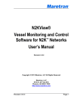
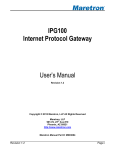
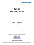
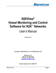
®
Linksys® E2500 Wireless-N Router
Configuration Guide
Revision 1.0
Copyright © 2012 Maretron, LLP All Rights Reserved
Maretron, LLP
9014 N. 23rd Ave #10
Phoenix, AZ 85021-7850
http://www.maretron.com
Maretron Manual Part #: M003030
Revision 1.0
Page 1
Linksys® E2500 Wireless-N Router Configuration Guide
Revision History
Rev.
1.0
Page 2
Description
Original document
Revision 1.0
®
Table of Contents
1 Introduction ...........................................................................................................................4 2 Configuring the WiFi/Router ..................................................................................................6 2.1 Connecting to the WiFi/Router ................................................................................. 6 2.2 Adding an IPG100 to the Network ............................................................................ 9 2.3 Adding a PC based N2KServer® to the Network. ................................................... 12 2.4 Adding a MBB100 N2KView Client to the Network ................................................. 14 2.5 Adding a DSM800, TSM800, or TSM1330 N2KView Client to the Network ........... 15 2.6 Adding a Wired PC N2KView Client to the Network ............................................... 15 2.7 Adding a Wireless PC N2KView Client to the Network ........................................... 16 2.8 Adding a Mobile N2KView Client to the Network .................................................... 16 3 Resetting the WiFi/Router to Maretron Configuration .......................................................... 17 3.1 Physically Reset the WiFi/Router ........................................................................... 17 3.2 Opt out of the Cisco Connect ................................................................................. 17 3.3 Give your Wireless Network a name ...................................................................... 19 3.4 Programming network security ............................................................................... 20 Appendix A- Client/Server Architecture ............................................................................. 22 A.1 Examples of NMEA 2000® Client/Server Architectures ......................................... 23 A.2 TCP/IP Networks .................................................................................................... 24 A.3 NAT (Network Address Translation) ....................................................................... 25 A.4 PAT (Port Address Translation) .............................................................................. 25 A.5 Static and Dynamic IP Addressing ......................................................................... 26 A.6 Software Firewall Configuration .............................................................................. 26 A.7 Data Security and Encryption ................................................................................. 26 Table of Figures
Figure 1 - Typical WiFi/Router Connection ................................................................................ 4 Figure 2 – LAN Client/Server Architecture Example with USB100 .......................................... 23 Figure 3 – WAN Client/Server Architecture Example through the Internet .............................. 23 Figure 4 – LAN Client/Server Architecture Example with IPG100 ........................................... 24 Revision 1.0
Page 3
Linksys® E2500 Wireless-N Router Configuration Guide
1
Introduction
Thank you for purchasing the Maretron preconfigured Linksys® E2500 Wireless-N Router (from
here on referred to as WiFi/Router). The WiFi/Router is used to interconnect one or more wired
or wireless devices running Maretron’s N2KView® vessel monitoring and control software with
a device running Maretron’s N2KServer® (i.e., N2KServer® runs on Maretron’s Internet
Protocol Gateway (IPG100) or a PC connected to an NMEA 2000® network via Maretron’s
USB gateway (USB100)). Figure 1 shows a typical configuration where multiple devices
running Maretron’s N2KView® software (e.g., laptop computer, desktop computer, smart
phone, tablet, Maretron DSM800 display, or Maretron MBB100 black box) are connected back
to an NMEA 2000® network through the WiFi/Router and the Maretron Internet Protocol
Gateway (IPG100).
Figure 1 - Typical WiFi/Router Connection
Although the WiFi/Router is mostly pre-configured by Maretron, there are a few steps that must
be performed to establish the connection between Maretron’s N2KView® vessel monitoring
Page 4
Revision 1.0
®
and control software (client) and Maretron’s N2KServer® (server). If you are installing a system
similar to Figure 1 where the N2KServer® is running on the IPG100, then you should read
paragraphs 2, 2.1 and 2.2 (skip paragraph 2.3). If you are installing a system where
N2KServer is running on a PC then you should read paragraphs 2, 2.1 and 2.3 (skip paragraph
2.2).
Revision 1.0
Page 5
Linksys® E2500 Wireless-N Router Configuration Guide
2
Configuring the WiFi/Router
The settings in the WiFi/Router are changed using a web browser such as Internet Explorer,
Safari, or Mozilla Firefox.
2.1
Connecting to the WiFi/Router
Connect the WiFi/Router to your PC using the blue Ethernet cable supplied in the box. Use the
supplied AC adapter to power the WiFi/Router.
Open your Internet browser and type 192.168.1.1 in the address field, and then press Enter. If
you connect successfully to the router, the browser will display a screen requesting a
username and password.
For Mozilla Firefox, this would look like:
and for Internet Explorer the corresponding screens would be:
Page 6
Revision 1.0
®
From now on, we will just show one set of browser screens – the screens from other browsers
will be very similar.
Leave the User name blank, and enter the default Password, which is admin and press the
OK button.
You may see the following message:
Cisco connect is a utility that comes with the router. It generalizes the setup procedures, but
we will not be using it to configure the WiFi/Router, so press the OK button to remove the
message.
Revision 1.0
Page 7
Linksys® E2500 Wireless-N Router Configuration Guide
You are now connected to the WiFi/Router, and should see the following basic setup screen.
Page 8
Revision 1.0
®
Whenever you make a change to the configuration, you will see the following message:
You can press Continue whenever this message is displayed to get back to the configuration
screens.
2.2
Adding an IPG100 to the Network
Connect Maretron’s Internet Protocol Gateway (IPG100) to the WiFi/Router using an Ethernet
Cable. The cable plugs into one of the blue Ethernet sockets at the back of the router. Reset
the IPG100 by removing the NMEA 2000® cable and re-attaching it. This forces the IPG100 to
connect to this router, and removes previously allocated addresses.
Now we want to get the MAC address of the IPG100, so that we can reserve an IP Address for
it. Having a constant, reserved IP Address for the IPG100, makes it easy for N2KView® clients
to find the IPG100 on the network. We will choose to use the address 192.168.1.3 for the
IPG100. Note that if you have more than one IPG100 or PC-based N2KServer®, then each one
must have a unique reserved address, but this is beyond the scope of these instructions, so
please contact Maretron Technical Support for assistance.
Inside the WiFi/Router is a DHCP Server, which is responsible for assigning IP addresses to
other network devices that request them. DHCP stands for Dynamic Host Configuration
Protocol.
The IPG100 on the network will be identified by the Client Name of IPG100_<serial number>.
Revision 1.0
Page 9
Linksys® E2500 Wireless-N Router Configuration Guide
From the Basic Setup page, open the DHCP Reservation Table by pressing the DHCP
Reservation button.
The DHCP Reservation table is displayed as shown below:
If you do not see an IPG100 in the top part of the table, then it has not requested an address
from the DHCP Server. Ensure that DHCP is set to Yes in the device configuration of the
IPG100 (refer to the IPG100 manual).
Carefully copy the Client Name and MAC Address for the IPG100 from the top table to the
second table. Set the assigned IP Address for the IPG100 to 192.168.1.3.
Page 10
Revision 1.0
®
Press Add Clients to add the IPG100 to the table:
Press Save Settings and then Close.
To make these settings take effect, reset the IPG100 by disconnecting the NMEA 2000® cable,
and then re-connecting.
Revision 1.0
Page 11
Linksys® E2500 Wireless-N Router Configuration Guide
2.3
Adding a PC based N2KServer® to the Network.
In addition to the PC connected to the WiFi/Router used to configure the WiFi/Router, also
connect the PC slated to run the N2KServer® to the WiFi/Router using an Ethernet Cable. The
cable plugs into one of the blue Ethernet sockets at the back of the WiFI/Router.
Now we want to get the MAC address of the PC running N2KServer®, so that we can reserve
an IP Address for it. Having a constant, reserved IP Address for N2KServer®, makes it easy for
N2KView® clients to find N2KServer® on the network. We will choose to use the address
192.168.1.3 for the N2KServer®. Note that if you have more than one IPG100 or PC-based
N2KServer®, then each one must have a unique reserved address, but this is beyond the
scope of these instructions, so please contact Maretron Technical Support for assistance.
Inside the WiFi/Router is a DHCP Server, which is responsible for assigning IP addresses to
other network devices that request them. DHCP stands for Dynamic Host Configuration
Protocol.
The PC running N2KServer® on the network will be identified by name of the PC.
From the Basic Setup page, open the DHCP Reservation Table by pressing the DHCP
Reservation button.
Page 12
Revision 1.0
®
The DHCP Reservation table is displayed as shown below:
Carefully copy the Client Name and MAC Address for the PC from the top table to the second
table. Set the assigned IP Address for the PC to 192.168.1.3.
Revision 1.0
Page 13
Linksys® E2500 Wireless-N Router Configuration Guide
Press Add Client to add the PC to the table.
Press Save Settings and then Close.
To make these settings take effect, disconnect and then reconnect the Ethernet cable to the
PC.
Note that if the PC containing N2KServer® is the same PC that you are working on, your
session will be disconnected as the PC is given its new address.
2.4
Adding a MBB100 N2KView Client to the Network
Connect Maretron’s Black Box (MBB100) to the WiFi/Router using an Ethernet Cable. The
cable plugs into one of the blue Ethernet sockets at the back of the router.
Open the Configuration Dialog on the MBB100 by clicking on the Configuration tab on the right
of the screen. In the Network Configuration section, ensure that the Use DHCP box is
selected. If it is not, click on the square to display the check mark and press the Update button.
The screen may blank for a couple of minutes while the change is applied.
Close the Configuration Dialog and open the Connections Dialog by clicking on the
Connections tab on the right of the screen.
In the N2KServer Connection section, press the Disconnect button, type the IP address of the
IPG100 or PC-based N2KServer.
Page 14
Revision 1.0
®
If the default values are used this should be 192.168.1.3. A message should be displayed at
the bottom left of the section stating that an IPG100 or N2KServer has been found, and giving
its IP Address.
Press the Connect button to establish the connection.
2.5
Adding a DSM800, TSM800, or TSM1330 N2KView
Client to the Network
Connect the DSM800/TSM800/TSM1330 to the WiFi/Router using an Ethernet Cable. The
cable plugs into one of the blue Ethernet sockets at the back of the router.
Open the Configuration Dialog on the DSM800/TSM800/TSM1330 by clicking on the
Configuration tab on the right of the screen. In the Network Configuration section, ensure that
the Use DHCP box is selected. If it is not, click on the square to display the check mark and
press the Update button. The screen may blank for a couple of minutes while the change is
applied.
Close the Configuration Dialog and open the Connections Dialog by clicking on the
Connections tab on the right of the screen.
In the N2KServer Connection section, press the Disconnect button, type the IP address of the
IPG100 or PC-based N2KServer.
If the default values are used this should be 192.168.1.3. A message should be displayed at
the bottom left of the section stating that an IPG100 or N2KServer has been found, and giving
its IP Address.
Press the Connect button to establish the connection.
2.6
Adding a Wired PC N2KView Client to the Network
Connect the PC to the WiFi/Router using an Ethernet Cable. The cable plugs into one of the
blue Ethernet sockets at the back of the router.
Using the Network Configuration tools supplied with the Windows Operating System, ensure
that DHCP is enabled.
Open the Connections Dialog by clicking on the Connections tab on the right of the screen.
In the N2KServer Connection section, press the Disconnect button, type the IP address of the
IPG100 or PC-based N2KServer.
If the default values are used this should be 192.168.1.3. A message should be displayed at
the bottom left of the section stating that an IPG100 or N2KServer has been found, and giving
its IP Address.
Revision 1.0
Page 15
Linksys® E2500 Wireless-N Router Configuration Guide
Press the Connect button to establish the connection.
2.7
Adding a Wireless PC N2KView Client to the Network
Using the Wireless Configuration programs supplied with the PC, connect to the Wireless
Network identified by the SSID written on the label affixed to the bottom of your router. When
prompted to enter the passphrase, enter the passphrase from the same label. If requested to
enter the type of security used by the wireless network, select the option WPA/WPA2.
Open the Connections Dialog by clicking on the Connections tab on the right of the screen.
In the N2KServer Connection section, press the Disconnect button, type the IP address of the
IPG100 or PC-based N2KServer.
If the default values are used this should be 192.168.1.3. A message should be displayed at
the bottom left of the section stating that an IPG100 or N2KServer has been found, and giving
its IP Address.
Press the Connect button to establish the connection.
2.8
Adding a Mobile N2KView Client to the Network
Mobile N2KView Clients may be iPads, iPhones, Android smart phones, etc.
Using the Wireless Configuration programs supplied with the device, connect to the Wireless
Network identified by the SSID written on the label affixed to the bottom of your router. When
prompted to enter the passphrase, enter the passphrase from the same label. If requested to
enter the type of security used by the wireless network, select the option WPA/WPA2.
In N2KView Mobile, press the Menu button at the top of the screen, and then the Settings
button to enter the Setting dialog. Type the IP address of the IPG100 or PC-based N2KServer.
If the default values are used this should be 192.168.1.3.
Press the Connect button to establish the connection.
Page 16
Revision 1.0
®
3
Resetting the WiFi/Router to Maretron
Configuration
In addition to the parameters that must be set by the user described in paragraph 2, several
parameters are set by Maretron at the factory. If the factory settings are ever lost, then you can
reset the WiFi/Router and program the factory setting by following the instructions outlined in
the following paragraphs.
3.1
Physically Reset the WiFi/Router
On the bottom of the WiFi/Router is a small red button. Hold it down until the lights at the top of
the router turn yellow (about 5 seconds). You router has now been reset to the original factory
configuration, and now needs the original Maretron configuration to be restored.
3.2
Opt out of the Cisco Connect
When you reset the WiFi/Router to the Cisco factory default configuration, it will ask you to
install the Cisco Connect software. We will not be using the Cisco Connect software to
configure the router, so click “Continue with an open and unsecured network”. We will be
securing the network ourselves in the following steps, so don’t worry.
Revision 1.0
Page 17
Linksys® E2500 Wireless-N Router Configuration Guide
You will now see another warning screen. Click the checkbox next to “I understand that my
network is currently open and not secure. I would like to manually configure my router’s
security settings.”, and then press the Continue button.
You will now see one more warning message. Click Do not show me this again, and then
click OK.
Page 18
Revision 1.0
®
You will now see the router’s manual configuration screen, and can proceed to the next steps.
3.3
Give your Wireless Network a name
When you connect a device to a router using the wireless connection, you are generally shown
a list of wireless devices to which you can connect. The name that you give to your router will
help you identify this router. The name will be preset to Maretron followed by the last five
digits of the router’s serial number.
Make sure that you are looking at the Basic Wireless Settings page, by clicking on Wireless
and then Basic Wireless Settings. These will both show white lettering on a blue background
when you are on the correct page.
Change the Configuration View to Manual.
Revision 1.0
Page 19
Linksys® E2500 Wireless-N Router Configuration Guide
There are two Network Name (SSID) fields, in both of them, replace the word Cisco with
Maretron, leaving the 5 digits from the serial number intact.
3.4
Programming network security
This section details the programming of WiFi/Router to ensure that wireless messages to and
from the router are encrypted against eavesdropping.
Make sure that you are looking at the Wireless Security page, by clicking on Wireless and
then Wireless Security.
Change the Security Mode to WPA2/WPA Mixed Mode for both the 5 GHz Wireless Security
and the 2.4 GHz Wireless Security categories.
Page 20
Revision 1.0
®
The Passphrase is used to encrypt the data passed between the router and wireless devices.
It must be entered identically on all wireless devices connected to the router. Maretron will
choose a secure passphrase, and attach a copy of it to the underside of the router. Carefully
enter this phrase into the Passphrase box in the above dialog, for both the 5 GHz Wireless
Security and the 2.4 GHz Wireless Security categories.
Every WiFi/Router will be pre-programmed with a different passphrase, so that if more than
one boat in close proximity have WiFi/Routers, their security will not be compromised.
Revision 1.0
Page 21
Linksys® E2500 Wireless-N Router Configuration Guide
Appendix A-
Client/Server Architecture
The N2KView® Vessel Monitoring and Control System is based on a client/server architecture.
In this context, a server is defined as a component that provides services over a network and a
client is defined as a station that requests and uses those services.
Within the N2KView® System, there is generally one server (called N2KServer®) and one or
more stations or clients (called N2KView®). The server component is implemented by either an
IPG100 or N2KServer® software running on a Windows PC, and the station or client
components are implemented by the N2KView® software. N2KView® software may run on a
Windows PC, Mac, or Maretron®’s MBB100 or DSM800. Mobile versions of N2KView®
software are available for iPod Touch, iPhone, iPad and most Android devices. The service
offered by the server to the stations (clients) is access to the NMEA 2000® network data that
the server receives from the NMEA 2000® network via its NMEA 2000® gateway. The network
over which this service is offered is implemented as a TCP/IP (Transmission Control
Protocol/Internet Protocol) network, which is discussed in the next section.
Page 22
Revision 1.0
®
A.1 Examples of NMEA 2000® Client/Server Architectures
N2KServer® may run on a Windows PC (using Maretron’s USB100 gateway - see Section 2.3)
or N2KServer® may run directly on an IPG100 (see Figure 2).
Figure 2 – LAN Client/Server Architecture Example with USB100
Figure 2 shows an example of a Local Area Network (LAN) connection including the PC to
NMEA 2000®network connection through a USB100 gateway. A copy of N2KServer® must run
on the PC connected to the USB100, and an N2KView® Hardware License Key must be
plugged in to the PC to supply sufficient licenses for the maximum number of simultaneously
connected clients. N2KView® clients may run on either the PC connected to the USB100, or to
another PC connected to the router, or to a laptop or mobile device connected wirelessly.
LAN
WAN
Figure 3 – WAN Client/Server Architecture Example through the Internet
Revision 1.0
Page 23
Linksys® E2500 Wireless-N Router Configuration Guide
Figure 3 extends the example shown in Figure 2by adding an external internet access point
across a Wide Area Network (WAN). Although it is possible to setup the network as shown in
Figure 3, ensuring that the remote N2KView® clients can find the IP Address of the
N2KServer® at the correct port (6543 or 6544) requires considerable IT expertise.
Figure 4 – LAN Client/Server Architecture Example with IPG100
Figure 4 shows an example of an IPG100 connected between the NMEA 2000® network and a
Wi-Fi/router connected to a PC running an N2KView® client. A copy of N2KServer®
automatically runs on the IPG100; however an N2KView® Hardware License Key must be
plugged in to the IPG100 to supply sufficient licenses for the maximum number of
simultaneously connected clients. As in the previous examples, N2KView® Clients may run on
any computer able to access the N2KServer® on the Ethernet network.
A.2 TCP/IP Networks
The networking protocol that is used for the communication between the server and stations in
the N2KView® system is the TCP/IP protocol. This protocol is used by the World Wide Web,
FTP (File Transfer Protocol), and many others of the most popular applications on the Internet.
The TCP/IP connection can be made over an Ethernet connection, a Wi-Fi connection, cellular
phone data connection, and many other types of media. In fact, a single packet of TCP/IP
data may traverse multiple types of media on its journey. The TCP/IP protocol is natively
supported by Microsoft Windows XP and Microsoft Windows Vista, as well as Internetconnected cellular phones.
Each computer on a TCP/IP network is identified by an IP address unique to that network. An
IP address consists of four numbers, each ranging between 0 and 255, separated by periods.
This is referred to a dotted decimal notation. Examples of IP addresses in this format are
10.0.0.1, and 62.12.31.188.
The IP address may either be hard coded into the computer (this means that the address is
static which makes the computer easier to find) or assigned at each startup by a DHCP server,
Page 24
Revision 1.0
®
typically found as part of a router. The router can be configured to reserve a specific address
for the computer and then assign that same address each time at startup. If the router chooses
a different address each time, then the computer may be difficult to find on the network. This is
not a problem for a client such as N2KView®, but servers such as N2KServer® or the IPG100
must be at a known address.
A.3 NAT (Network Address Translation)
If you wish to use N2KView® to view data from an N2KServer® on a WAN through an Internet
connection, please read this section. If your N2KServer® and N2KView® computers are on the
same LAN, you may skip this section.
In the early days of the Internet, each computer connected to the Internet had its own IP
address. With the explosive growth of the Internet, the number of distinct IP addresses is
starting to run out. It is no longer practical for an Internet Service Provider (ISP) to provide its
customers with individual IP addresses for each component the customer wishes to connect to
the Internet. Rather, the ISP normally assigns each customer a single IP address, and a
router implementing Network Address Translation (NAT) is connected to the Internet
connection (sometimes referred to as the Wide Area Network, or WAN, connection) on one
side, and to the Local Area Network, or LAN, on the other side. Each computer on the LAN
side of the connection will be assigned its own IP address, typically in the ranges 192.168.x.x,
10.x.x.x, and 172.16.x.x through 172.31.x.x, where x can be any number in the range 0-255.
The WAN connection will be assigned a single IP address by the ISP.
Generally, network address translation is performed by a router that is connected to the
Internet via a Cable or DSL connection on the WAN side, and to the local area network (LAN)
via Ethernet or Wi-Fi connections. In order to access an N2KServer® on the local area
network from an N2KView® outside of the LAN. You must configure the router to allow
incoming connections on port 6544 and to forward these connections to the IP address of the
N2KServer® computer. Consult the documentation that came with your router for details.
A.4 PAT (Port Address Translation)
If you wish to use N2KView® to view data from an N2KServer® on a WAN through an Internet
connection and your Internet Service Provider does not allow communication on port 6544,
please read this section. If your N2KServer® and N2KView® computers are on the same LAN,
or your ISP allows communication over port 6544, you may skip this section.
N2KServer® requires a connection to be made on port 6544. Routers that support Port
Address Translation can be set up to accept incoming connections on a different port and to
forward these connections to port 6544 on the IP address of the N2KServer® computer. This
change in the port address is known as the ability to do Port Address Translation as well as
Network Address Translation. Not all routers have this ability; please consult the
documentation that came with your router for details.
Revision 1.0
Page 25
Linksys® E2500 Wireless-N Router Configuration Guide
N2KView® must then be set up to request a connection to the WAN IP Address of the router
and the new port number.
A.5 Static and Dynamic IP Addressing
If you wish to use N2KView® to view data from an N2KServer® on a WAN through an Internet
connection, please read this section. If your N2KServer® and N2KView® computers are on the
same LAN, you may skip this section.
If you request a Static IP Address from your ISP when you set up your Internet connection, the
WAN IP address will always be the same. If you didn’t make this request, your ISP will assign
you a Dynamic IP Address, which may actually change from time to time. In this way, the ISP
only needs to have enough addresses to cover its customers who are connected to the
Internet at any given time. If you stop or lose your Internet connection, your Dynamic IP
address will be released and may be reassigned to someone else.
If you wish to connect to an N2KServer® from outside your vessel’s LAN via an Internet
connection, you have two choices. First, you can request a static IP address from the ISP for
your vessel; secondly, you may register your N2KServer®’s IP address with a “dynamic DNS
service”, such as the ones offered freely by www.dyndns.org, among others. Please visit their
websites for more information on how dynamic DNS services operate.
A.6 Software Firewall Configuration
If you wish to run N2KView® and N2KServer® on two separate computers and are running a
software firewall product other than Windows Firewall, please read this section. Otherwise,
you may skip this section.
A firewall is designed to protect your computer from unfettered access from the Internet.
There are two kinds of firewalls: software and hardware. A software firewall is a component
such as Windows Firewall or Norton Internet Security. A major function of these programs is to
allow your computer to initiate connections out onto the Internet, but to block your computer
from receiving incoming connections from the Internet. If you wish to be able to view your
vessel’s data from another computer, your N2KServer® computer’s software firewall must be
configured to allow incoming connections from N2KView® stations. The N2KServer® makes
these adjustments to the Windows Firewall software when it is installed. If you are running
firewall software from another vendor, you may have to configure your firewall software to
allow this incoming TCP protocol connection on port 6544.
A.7 Data Security and Encryption
Making your vessel’s data available over local networks or the internet presents multiple
security concerns. First, it is desirable to keep anyone from viewing your vessel’s data without
authorization. Second, and more important, it is imperative that no unauthorized persons be
able to place data onto your vessel’s NMEA 2000® network.
Page 26
Revision 1.0
®
The N2KView® system protects your vessel’s data with multiple levels of protection.
First, any data that passes between the N2KServer® server component and any N2KView®
station components is protected using industry-standard SSL encryption. This encryption
standard is widely used to protect financial information on the internet. Each communication
session negotiates a random encryption key every time a connection is established. This
makes the data secure over public and private Wi-Fi networks, as well as the internet.
Second, each N2KView® station that wishes to connect to an N2KServer® server component
must authenticate itself by means of a server password. The server password is transmitted
by the N2KView® station to the N2KServer® server over the encrypted communication link.
The N2KServer® compares the server password to the one it was programmed with. Only if
the server password received from the station matches the server’s stored password is the
station granted access to the NMEA 2000® network data.
Third, access to the Router itself can be protected through passwords and the data flowing
through the router over wireless connections can be encrypted (scrambled) using a pass
phase.
Revision 1.0
Page 27