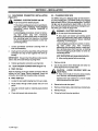
1
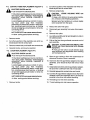
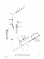
February
IMPORTANT Read
and
understand
the
entire
Effective With
manual, with special emphasis on
the safety material throughout the manual, before
contents of this
installing, operating,
or
maintaining
this
1989
Style
FORM:
No. JG-20
equip
This unit and these instructions are for use
only by persons trained and experienced in the safe
operation of welding equipment. Do not allow un
ment.
trained persons to install, operate, or maintain this
unit. Contact your distributor if you do not fully
understand these instructions.
OWN ERS
MANUAL
AUTOi~J
MILLER ELECTRIC MFG. Co.
718 S. BOUNDS ST. P.O. Box 1079
APPLETON, WI 54912 USA
ADDITIONAL COPY PRICE 35 CENTS
NWSA CODE NO. 4579
PRINTED IN U.S.A.
MODEL
AUTO ARC
MWG 160
MWG 160B
112934
ONEYEARLIMITEDWARRANTY
Miller Electric Mfg. Co. warrants to the buyer
for personal,
purchases this Auto Arc Welder (Welder)
that this Welder
family or household purposes (Consumer)
will be free from defects in material and workmanship for a
period of one year from the date of purchase. This warranty
covers only the original purchaser of this Welder. Miller Electric
does not authorize any party, including its authorized
distributors, to offer any other warranty on behalf of Miller
Electric. Upon expiration of the warranty period, Miller Electric
shall have no further liability related to the Welder, except on
warranty claims made during the warranty period.
COVERAGE
-
who
(4
~?
~
(
THIS WARRANTY IS OFFERED IN LIEU OF ANY OTHER
~
(4
EXPRESS WARRANTY; AND, EXCEPT TO THE EXTENT
PROHIBITED BY APPLICABLE LAW, THE DURATION OF
IMPLIED
ALL
WARRANTIES, INCLUDING BUT NOT
LIMITED TO THE IMPLIED WARRANTIES OF MERCHANTABILITY AND FITNESS FOR A PARTICULAR PURPOSE, IS
LIMITED TO THE DURATION OF THIS WARRANTY.
Some states do not allow limitations
~
(4
on
long an implied
not apply to you.
how
warranty lasts, so the above limitation may
This warranty gives you specific legal rights, and you may also
have other
rights which
vary from state to state.
REMEDY FOR DEFECTIVE WELDER
Upon receipt of any
defective Welder. Miller Electric will, at its option, repair or
replace the defective Welder at its expense, refund or credit
-
the
purchase price (less
tual use),
or
reasonable
depreciation based
on ac-
replacement
provided that the purchaser of that Welder has followed the
procedure for obtaining warranty performance set forth below.
The Welder so repaired or used as a replacement will be ship
ped to the purchaser of the defective Welder, with transporta
tion charges prepaid to any destination in the continental
United States (transportation charges on shipments to Alaska
or Hawaii will be paid only to the nearest port of export).
PURCHASERS
THE
(
reimburse the Consumer for the cost of repair or
at an approved Miller Electric warranty station,
REMEDIES
FOR
A
c~
DEFECTIVE
WELDER, TO THE EXTENT PERMITTED BY APPLICABLE
LAW, ARE LIMITED TO THE REMEDY PROVIDED BY THIS
WARRANTY:
AND, TO THE EXTENT ENFORCEABLE
UNDER APPLICABLE LAW, MILLER ELECTRIC SHALL IN
NO EVENT BE LIABLE FOR CONSEQUENTIAL, INCIDENTAL
OR SPECIAL DAMAGES ARISING OUT OF THE USE OF, OR
INABILITY TO USE, THE WELDER, WHETHER BASED ON
BREACH OF THIS WARRANTY, MILLER ELECTRICS
NEGLIGENCE OR OTHER TORT, OR ON ANY THEORY OF
4
STRICT LIABILITY.
specified below, Millers warranty does not apply
to components having normal useful life of less than one (1)
year, such as spot welder tips, relay and contactor points,
parts that come in contact with the welding wire including
Except
~
~
as
nozzles and nozzle insulators where failure does not result from
defect in workmanship
or
Some
states do not
allow the exclusion
sequential or incidental damages,
not apply to you.
so
or
limitation of
con
the above limitations may
material.
PROCEDURE FOR OBTAINING WARRANTY PERFORMANCE
Miller shall be
within the
~
to
Equipment
following periods
to the original user:
ranted
ment
honor warranty claims
in the event of failure resulting from
required
from the date of
on
a
war-
defect
delivery of Equip-
1. Arc
1 year
welders, power sources, and components
3 years
Original main power rectifiers
1 year only)
(labor
3. All welding guns, feeder/gunsand plasma torches... BOdeyS
4. Replacement or repair parts, exclusive of labor
60 days
2
As soon as any defect in a Welder becomes known, the pur
chaser of the Welder must, within thirty (30) days, notify an
approved Warranty Station or Miller Electric in writing of the
defect. The purchaser must then, within the one year warranty
period. return the Welder to Miller Electric at the following address:
-
..
Miller Electric
Mfg. Co.
718 South Bounds Street
Box 1079
WHAT IS NOT COVERED
subjected
warranty repair by anyone except Miller Electric. Further, this
warranty only extends to those purchasing the Welder for personal, family or household purposes. Commercial and in
dustrial users are given a different warranty.
to
~Q
any Welder
This warranty does not extend
to misuse, neglect, accident, or in-
Appleton,
-
All
Wisconsin
54912
transportation charges
must be
prepaid.
to
Warranty Station
or
Miller Electric
~
TABLE OF CONTENTS
Section No.
SECTION 1
Page
INTRODUCTION
1-1.
General Information And
1-2.
Receiving-Handling
Description
Duty Cycle
1-3.
1-4.
SECTION 2
Safety
Gun/Feeder Connector Installation
2-2.
Gun
SECTION 3
Trigger Connections
Changing Wire Size
Gas Metal Arc Welding (GMAW)
Flux Cored Arc Welding (FCAW)
3-3.
Shutting
SECTION 4
4-1.
4-2.
4-3.
1
1
2
2
2
SEQUENCE OF OPERATION
3-2.
3-1.
1
INSTALLATION
2-1.
2-3.
1
Down
3
3
4
MAINTENANCE
And
Upkeep
Contact Tube Replacement
Liner Replacement
Inspection
4
5
5
No.
SECTION 1
Wire
Ampere Rating
60/~ Duty Cycle
Diameter
0.023 in. (.6 mm)
0.030 in. ~.8 mm)
160 Amperes
With
CO2
Cooling
Length
Method
10 ft.
(3.05 m)
1-1.
GENERAL INFORMATION AND SAFETY
Information
I
Net
Ship
2.8 lbs.
Air
5.4 lbs.
(1.3 kg)
(2.4 kg)
Specifications
1-2.
RECEIVING-HANDLING
installing this equipment, clean all packing mate
carefully inspect for any
have
that
occurred
damage
during shipment. Any
may
claims for loss or damage that may have occurred in
transit must be filed by the purchaser with the carrier. A
copy of the bill of lading will be furnished by the manu
facturer on request if occasion to file claim arises.
Before
presented
in this manual and
various la
on
bels, tags, and plates on the unit pertains to equipment
design, installation, operation, maintenance, and
troubleshooting which should be read, understood, and
followed forthe safe and effective use of this
equipment.
Safety
B.
Weight
I
General
A.
INTRODUCTION
Cable
Figure
1-1.
-
rial from around the unit and
requesting information concerning this equip
ment, it is essential that Model Description and Style
When
The
and
installation,
maintenance,
operation,
of
arc
welding equipment requires prac
troubleshooting
procedures which ensure personal safety and
the safety of others. Therefore, this equipment is to be
installed, operated, and maintained only by qualified
persons in accordance with this manual and all applica
Number of the
be
equipment
supplied.
tices and
ble codes such as, but not limited to, those listed at the
end of Section 1
Safety Rules For Operation Of Arc
-
Welding
Power Source.
Safety instructions specifically pertaining to this unit ap
pear throughout this manual highlighted by the signal
words WARNING and CAUTION which identify differ
ent levels of hazard.
carefully
or
procedures
practices which if not
serious personal injury
or
followed could result in
loss of life.
CAUTION statements include installation, operation,
and maintenance procedures or practices which if not
carefully followed could result in minor personal injury or
damage to this equipment.
A third
signal word, IMPORTANT highlights instruc
special emphasis to obtain the most ef
ficient operation of this equipment.
tions which need
DESCRIPTION
This unit is
an
air-cooled semiautomatic Gas Metal Arc
Welding (OMAW)
or
Flux Cored Arc
gun. The MWG 160 gun is
Welding (FCAW)
shipped ready to feed 0.023
(0.6 mm) welding wire. The MWG 160B gun is
shipped ready to feed 0.030 in (0.8 mm) welding wire.
To change wire size, see Section 2-3.
in.
1-4.
The
DUTY CYCLE
of a welding gun is the percentage of a
period that a gun can be operated at a given
duty cycle
ten minute
WARNING statements include installation, operation,
and maintenance
1-3.
load. This gun is rated at 60% duty cycle using CO2
gas. This means that the gun can be oper
ated six minutes out of every ten with the CO2 gas
shielding
shielding.
The
be idle to
permit proper cooling.
4A
remaining
four minutes the gun should
CAUTION:
EXCEEDING THE RATED AM
PERAGE WITH CO2 OR FAILING TO RE
DUCE THE WELDING AMPERAGE OR DUTY
CYCLE WHEN USING A MIXED SHIELDING
GAS can result In damage to the gun.
Do not exceed rated amperage when
using
C02.
Operate at 30% duty cycle
shielding gases.
when
using mixed
112934 Paael
SECTION 2
2-1.
GUN/FEEDER CONNECTOR INSTALLATION
(Figure 4-1)
a
2-3.
CHANGING WIRE SIZE
The MWG 160 gun is shipped ready to feed 0.023 in.
(0.6 mm) welding wire. The MWG 1 60B gun is shipped
WARNING: ELECTRIC SHOCK can kill.
Do not touch live electrical parts.
redytofeed
Shut down
160 gun can be converted to feed 0.035 in. (0.9 mm)
wire. Only the contact tube needs to be changed to per
welding po wersource and discon
input power employing lockout/tagging
procedures before installing, inspecting, or
servicing gun.
nect
Lockout/tagging procedures consist of remov
ing input power plug from receptacle,
padlocking line disconnect switch in open posi
tion, removing fuses from fuse box, or shutting
off and red-tagging circuit breaker or other dis
connecting device.
1.
INSTALLATION
a
2-2.
A.
2.
4.
kill.
Do not touch live electrical parts.
Shut down wire feeder and welding power
and disconnect input power employing
lockout/tagging procedures before installing,
inspecting,
or
servicing gun.
Insert gun into wire drive assembly until gun/feeder
stop is flush against wire drive as
sembly.
HOT SURFACES
gun/feeder connector securing
assembly.
knob on
Tighten gun/feeder connector securing
GUN TRIGGER CONNECTIONS
as
pos
knob.
(Figure 4-1)
Allow
can cause severe
burns.
cooling period before servicing.
1.
Remove nozzle.
2.
Cut off any portion of the electrode wire which
tends beyond end of contact tube.
ex
MWG 160 Gun
the
a
the
MWG16OBGun
CAUTION:
Spooled
Locate the two leads
hanging
Route leads through small
hole
on
front
Securely
panel.
connect leads to
Close and
112934
Page
2
secure
side
wire has
door.
tendency to unravel rapidly
spool.
3.
Retract wire onto wire
4.
Remove contact tube, and install
5.
Reinstall nozzle.
6.
Thread wire and resume
matching leads behind
access
can
when loosened from the
free from gun cable.
access
LOOSE WELDING WIRE
Injury.
Keep a firm hold on the wire during installa
tion, removal, and threading operations.
cause
panel.
3.
can
source
connector and rotate the threaded collar clockwise.
1.
WARNING: ELECTRIC SHOCK
connector hex
Loosen
Align the keyway on the gun switch connector with
keyway on the Trigger Control receptacle. Insert
B.
larger wire.
Lockout/tagging procedures consist of remov
ing input power plug from receptacle,
padlocking line disconnect switch in open posi
tion, removing fuses from fuse box, or shutting
off and red-tagging circuit breaker or other dis
connecting device.
IMPORTANT: The gun liner should be as close
sible to the drive rolls without touching them.
3.
(0.8 mm) welding wire. The MWG
mit either gun to feed the
wire drive
2.
0.030 in.
spool.
new
operation.
contact tube.
SECTION 3- SEQUENCE OF OPERATION
a
WARNING: ELECTRIC SHOCK can kill.
1.
Do not touch live electrical parts.
RAYS, SPARKS, AND HOT SURFACES
skin; NOISE can damage
hearing.
Wear correct eye, ear, and body protection.
Ensure that proper electrical connections have
been made to the welding power source and wire
feeder.
ARC
can
burn eyes and
FUMES AND GASES
your health.
Ventilate to keep
can
from
seriously
WELDING
Ensure
3.
shielding gas
is connected to
valve.
that
welding wire
has
been
properly
threaded and that correct initial tensions have been
set on drive rolls.
breathing fumes and
inadequate,
WIRE
shielding gas
harm
gases.
If ventilation is
breathing device.
Ensure that proper
2.
use
4.
Turn
5.
Place controls
approved
on
shielding gas supply.
wire feeder in
the
welding power source and
required position for the welding
on
setup.
can
puncture
cause
6.
Energize welding power
source
and wire feeder.
wounds.
Do not point gun toward any part of the
or other personnel.
body
SLAG
can
HOT METAL, SPATTER,
fire and burns.
AND
cause
Watch forfie.
Have a fire
how to use it.
extinguisher nearby,
and know
IMPORTANT: When installing new equipment, or after
prolonged shutdown, allow shielding gas to flow con
tinuously for at least one minute prior to welding to purge
the shielding gas line. To avoid wasting wire while purg
ing, loosen pressure adjustment knob on drive assem
bly, and pivot free from cover.
7.
Press
button on the wire feeder (if applica
roll cover and press gun switch to
drive
ble)
open
line.
purge gas
Purge
or
Allow work and equipment to cool before han
dling.
8.
Close drive roll
cover
and
adjust
tension.
MAGNETIC FIELDS FROM HIGH CURRENTS
can
affect
9.
pacemaker operation.
Wearers should consult with their doctor be
fore going near arc welding, gouging, or spot
welding operations.
See Section 1
Safety Rules For Operation Of
Arc Welding Power Source for basic welding
safety information.
-
a
EXCEEDING THE RATED AM
PERAGE WITH CO2 OR FAILING TO RE
DUCE THE WELDING AMPERAGE OR DUTY
CYCLE WHEN USING A MIXED SHIELDING
GAS can result in damage to the gun.
when
3-1.
12. After the controls on the
wire feeder have been
tion, welding power
(12.7
welding power
source
and
for normal opera
and wire feeder will
adjusted
source
function
automatically whenever the gun trigger is
pressed. Releasing the trigger will extinguish the
arc
using mixed
3-2.
and
cause
wire feed and gas flow to stop.
FLUX CORED ARC WELDING
(FCAW)
IMPORTANT: Read the warning information at the be
ginning of Section 3- SEQUENCE OF OPERATION be
fore operating.
1.
Ensure that proper electrical connections have
been made to the welding power source and wire
feeder.
2.
Ensure that welding wire has been properly
threaded and that correct initial tensions have been
set on drive rolls.
GAS METAL ARC WELDING (GMAW)
IMPORTANT: Read the warning in formation at the be
ginning of Section 3- SEQUENCE OF OPERATION be
fore operating.
1/2 in.
slippage is noticed, tighten drive roll pressure ad
justment 1/4 turn at a time until slippage stops. Do
not overtighten.
using
IMPORTANT: For welding wire threading, drive roll ad
justment, welding power source, or wire feeder control
in formation, see the appropriate Owners Manual.
approximatey
11. Press the gun trigger. Gas will start to flow, wire will
start to feed, and the arc will be established. If wire
CO2.
Operate at 30% duty cycle
shielding gases.
trigger or Jog button on the wire
(if applicable) to run wire out beyond end of
gas nozzle. Cut wire off so it sticks out approxi
mately 1/4 to 3/8 in. (6.4 to 9.5 mm) from nozzle.
10. Hold end of gas nozzle
mm) from workpiece.
CAUTION:
Do not exceed rated amperage when
Actuate the gun
feeder
112934
Pac,A3
Place controls
3.
wire feeder in
the
welding power source and
required positions for the welding
on
7.
After the controls on the
wire feeder have been
tion, welding power
setup.
welding power source and
adjusted for normal opera
source
and wire feeder will
automatically whenever the gun trigger is
pressed. Releasing the trigger will extinguish the
arc and stop the wire from feeding.
function
Actuate gun
4.
trigger or Jog button on the wire feeder
beyond the nozzle. Cut wire off so it
approximately 0.25 in. (6.4 mm).
to run wire out
sticks out
5.
6.
Hold the gun approximately 0.50 in.
the workpiece.
from
(12.8 mm)
Press the gun trigger. Wire will start to feed and the
arc will be established. If wire slippage is noticed,
tighten drive roll pressure adjustment 1/4 turn
time until slippage stops. Do not overtighten.
at a
3-3.
SHUTIING DOWN
1.
Stop welding.
2.
Turn off
3.
If used, turn off the
a
welding power
source
and wire feeder.
shielding gas
at the source.
WARNING:
HIGH CONCENTRATION OF
SHIELDING GAS can harm health or kill.
Shut off gas
supply when
not in use.
SECTION 4- MAINTENANCE
4-1.
INSPECTION AND UPKEEP
Usage
and
shop
conditions will determine
and type of maintenance
a
6.
frequency
Blow out gun casing or liner with compressed air
whenever the wire or liner is removed.
required.
ELECTRIC SHOCK
can
kIll.
Do not touch live electrical parts.
Shut down
welding powersource and discon
input power employing lockouttagging
procedures before installing, inspecting, or
servicing gun.
nect
Tube
Lockoutitagging procedures consist of remov
ing input power plug from receptacle,
padlocking line disconnect switch in open posi
tion, removing fuses from fuse box, or shutting
off and red-tagging circuit breaker or other dis
connecting device.
HOT SURFACES
Allow
can cause severe
cooling period before servicing.
Inspect gun for broken areas, cracks, and loose
parts; tighten, repair, and replace as required.
2.
Carefully remove any weld spatter or foreign matter
which may accumulate around the nozzle opening.
3.
Remove any accumulation around the switch.
4.
Repair or replace as required all hose and cabling;
give particular attention to frayed and cracking insu
lation and areas where hose and cabling enter
equipment.
Remove grease and
ture from electrical
a
MWG 160B
burns.
1.
5.
Tube
grime from components;
Collet
mois
Adapter
parts and cables.
CAUTION: FLYING DIRT AND METAL PAR
TICLES can Injure personnel and damage
equipment.
Point gun liner only in a safe direction away
from personnel and equipment when cleaning
with compressed air.
TB-hO 831
Ref. 18-121 447
Figure
112934
Page
4
4-1.
Gun Parts Replacement
4-2.
CONTACT TUBE REPLACEMENT (Figure 4-1)
2.
Cut off any
tends
a
ELECTRIC SHOCK
can
kill.
3.
Do not touch live electrical parts.
welding powersource and discon
nect input power employing lockout/tagging
procedures before installing, inspecting, or
servicing gun.
Shutdown
Lockout/tagging procedures consist of remov
ing input power plug from receptacle,
padlocking line disconnect switch in open posi
tion, removing fuses from fuse box, or shutting
off and red-tagging a circuit breaker or other dis
connecting device.
portion of the electrode
beyond end of contact tube.
wire which ex
Remove contact tube.
a
CAUTION:
LOOSE WELDING WIRE
injury.
Keep a firm
can
cause
hold
on
the wire
during installa
tion, removal, and threading operations.
Spooled wire has tendency to unravel
when loosened from the spool.
4.
5.
Retract wire onto wire
Disconnect gun
rapidly
spool.
assembly from wire drive
assem
bly.
HOT SURFACES
can cause severe
burns.
6.
Allow
cooling period
before
7.
1.
Remove nozzle.
2.
Cut off any portion of the electrode wire which
tends beyond end of contact tube.
3.
Remove contact tube, and install
4.
Reinstall nozzle, and
resume
LINER REPLACEMENT
a
ELECTRIC SHOCK
new
8.
Lay
cable
the
cable/conduit).
contact tube.
4A
operation.
Do not touch live electrical parts.
9.
gun/feeder
Lockout/tagging procedures consist of remov
ing input power plug from receptacle,
padlocking line disconnect switch in open posi
tion, removing fuses from fuse box, or shutting
off and red-tagging circuit breaker or other dis
connecting device.
equipment.
Blow out gun
burns.
casing
whenever the wire
10. Insert
new
or
or
liner with
compressed
air
liner is removed.
liner into
gun/feeder adapter end of gun
Liner should be flush with end of head
tube.
11. Install collet onto liner and into
Be
gun/feeder adapter.
liner is still flush with end of head tube.
sure
12. Reinstall
appropriate
contact tube and nozzle.
13. Cut liner off at
gun/feeder adapter end so that when
assembly liner is as close as
the drive rolls without touching.
installed in wire drive
cooling period before servicing.
to
14. Reinstall gun to wire drive
Remove nozzle.
connector end of
CAUTION: FLYING DIRT AND METAL PAR
TICLES can Injure personnel and damage
possible
1.
coils in
assembly.
assembly.
servicing gun.
Allow
straight (no
Point gun liner only in a safe direction away
from personnel and equipment when cleaning
with compressed air.
kill.
can cause severe
out flat and
Pull out the liner from
gun
(Figure 4-1)
can
assembly
ex
Shut down welding powersource and discon
nect input power employing lockout/tagging
procedures before installing, inspecting, or
HOT SURFACES
Remove liner collet.
servicing.
15. Thread
welding
assembly.
wire and resume
operation.
112934
Page
5
Februaryl989
Effective With
PARTS
LIST
FORM: 112934
Style No. JG-20
8
5
3~
2
1
r
11
14
2
16
17
TC-11O 832
Figure A
112934
Page
1
-
Exploded
View Of MWG 160 Gun
Item
No.
Figure
Part
No.
A
Exploded
1
110793
2
110780
View Of Gun
HANDLE ASSEMBLY
3
NUT,MlOxl
110779 JACKET, head tube
4
110781
5
110795 TUBE, head
110782 SPRING ,nozzle
6
7
STOP,
8
8
113022
8
113020
8
1
2
1
nozzle
TUBE, contact .024 wire (MWG 160)
112751 TUBE, contact .030 wire (MWG 1 60B)
112747 NOZZLE, slip type 1/2 orifice
113018
NOZZLE, slip type 3/8 orifice
7
Quantity
Description
1
1
1
112743
110794
TRIGGER SWITCH ASSEMBLY
10
079878
HOUSING PLUG & PINS (MWG 160)
TERMINAL, male
10
047994
11
048834
12
112745
12
121 905
13
110784
13
120715
14
110796
15
079974
16
110797
17
110792
1
1
1
NOZZLE, spot-flat
NOZZLE, spot
9
079535
1
1
1
1
(consisting of)
1
4
TERMINAL, friction-female (MWG 160B)
CLAMP, cable (MWG 160)
LINER, .024 wire 10 ft. (MWG 160) (consisting of)
LINER, .030 wire 10 ft. (MWG 160B) (consisting of)
COLLET, liner .024 wire (MWG 160)
COLLET, liner .030 wire (MWG 1 60B)
ADAPTER, gun/feeder
0-RING, 1/2 ID x .103
SLEEVE, rubber
CABLE, lOft
2
1
1
1
1
1
1
2
1
1
Optional Equipment
BE SURE TO PROVIDE MODEL AND STYLE NUMBER WHEN ORDERING REPLACEMENT PARTS.
112 934
Page
2