1
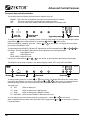
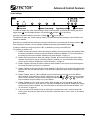
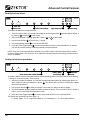
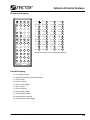
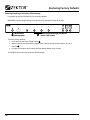
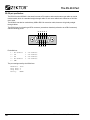
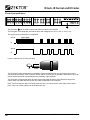
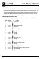
Home Theater Solutions HDS4x2 Component Video / Audio Matrix Switch Table of Contents What’s Inside.. ....................................................................................... 1 Thank you for your purchase!. . . . . . . . . . . . . . . . . . . . . . . . . . . . . . . . . . . . . . . . . . . . . . . . . . . . . . . . . 1 Features. . . . . . . . . . . . . . . . . . . . . . . . . . . . . . . . . . . . . . . . . . . . . . . . . . . . . . . . . . . . . . . . . . . . . . . . . 1 Overview of the HDS4x2........................................................................ 2 Front panel controls. . . . . . . . . . . . . . . . . . . . . . . . . . . . . . . . . . . . . . . . . . . . . . . . . . . . . . . . . . . . . . . . Rear Panel Connections . . . . . . . . . . . . . . . . . . . . . . . . . . . . . . . . . . . . . . . . . . . . . . . . . . . . . . . . . . . . Remote Control . . . . . . . . . . . . . . . . . . . . . . . . . . . . . . . . . . . . . . . . . . . . . . . . . . . . . . . . . . . . . . . . . . . Inserting the Remote Control’s Battery. . . . . . . . . . . . . . . . . . . . . . . . . . . . . . . . . . . . . . . . . . . . . . . . . 2 2 3 3 Getting Started (Quick Reference).. ....................................................... 4 Turning the HDS4x2 on or off. . . . . . . . . . . . . . . . . . . . . . . . . . . . . . . . . . . . . . . . . . . . . . . . . . . . . . . . . Mapping an input to an output zone. . . . . . . . . . . . . . . . . . . . . . . . . . . . . . . . . . . . . . . . . . . . . . . . . . . . Using the audio / video breakaway feature . . . . . . . . . . . . . . . . . . . . . . . . . . . . . . . . . . . . . . . . . . . . . . Sequencing through inputs. . . . . . . . . . . . . . . . . . . . . . . . . . . . . . . . . . . . . . . . . . . . . . . . . . . . . . . . . . . Mapping an input to an output zone using the remote control’s direct select buttons. . . . . . . . . . . . . . 4 4 4 5 5 Presets (User Defined Discretes).. ......................................................... 6 Programming a preset (a user defined IR discrete code). . . . . . . . . . . . . . . . . . . . . . . . . . . . . . . . . . . . 6 Unprogramming a preset. . . . . . . . . . . . . . . . . . . . . . . . . . . . . . . . . . . . . . . . . . . . . . . . . . . . . . . . . . . . 6 An example of defining a preset. . . . . . . . . . . . . . . . . . . . . . . . . . . . . . . . . . . . . . . . . . . . . . . . . . . . . . . 7 Initial Power On Settings.. ..................................................................... 8 Changing the initial power on settings. . . . . . . . . . . . . . . . . . . . . . . . . . . . . . . . . . . . . . . . . . . . . . . . . . 8 Advanced Control Features................................................................... 9 Setup mode overview (read this first). . . . . . . . . . . . . . . . . . . . . . . . . . . . . . . . . . . . . . . . . . . . . . . . . . . 9 Front panel display intensity and modes . . . . . . . . . . . . . . . . . . . . . . . . . . . . . . . . . . . . . . . . . . . . . . . 10 Control settings . . . . . . . . . . . . . . . . . . . . . . . . . . . . . . . . . . . . . . . . . . . . . . . . . . . . . . . . . . . . . . . . . . 11 Disabling front panel buttons. . . . . . . . . . . . . . . . . . . . . . . . . . . . . . . . . . . . . . . . . . . . . . . . . . . . . . . . 12 Disabling individual front panel buttons. . . . . . . . . . . . . . . . . . . . . . . . . . . . . . . . . . . . . . . . . . . . . . . . 12 Disabling the IR remote buttons. . . . . . . . . . . . . . . . . . . . . . . . . . . . . . . . . . . . . . . . . . . . . . . . . . . . . . 13 Disabling individual IR remote buttons. . . . . . . . . . . . . . . . . . . . . . . . . . . . . . . . . . . . . . . . . . . . . . . . . 13 Learning new IR codes. . . . . . . . . . . . . . . . . . . . . . . . . . . . . . . . . . . . . . . . . . . . . . . . . . . . . . . . . . . . . 14 IR remote button mapping. . . . . . . . . . . . . . . . . . . . . . . . . . . . . . . . . . . . . . . . . . . . . . . . . . . . . . . . . . 15 Extended IR mapping. . . . . . . . . . . . . . . . . . . . . . . . . . . . . . . . . . . . . . . . . . . . . . . . . . . . . . . . . . . . . . 15 Restoring Factory Defaults.. ................................................................ 16 Restoring everything to the factory default settings. . . . . . . . . . . . . . . . . . . . . . . . . . . . . . . . . . . . . . . 16 The RS-232 Port.. ................................................................................. 18 RS-232 port specifications. . . . . . . . . . . . . . . . . . . . . . . . . . . . . . . . . . . . . . . . . . . . . . . . . . . . . . . . . . 18 RS-232 protocol (overview). . . . . . . . . . . . . . . . . . . . . . . . . . . . . . . . . . . . . . . . . . . . . . . . . . . . . . . . . 19 IR Jack, IR Format and IR Codes......................................................... 20 IR control jack specifications . . . . . . . . . . . . . . . . . . . . . . . . . . . . . . . . . . . . . . . . . . . . . . . . . . . . . . . . IR format. . . . . . . . . . . . . . . . . . . . . . . . . . . . . . . . . . . . . . . . . . . . . . . . . . . . . . . . . . . . . . . . . . . . . . . . Remote IR codes (generated by the ZRM2) . . . . . . . . . . . . . . . . . . . . . . . . . . . . . . . . . . . . . . . . . . . . Extended IR codes. . . . . . . . . . . . . . . . . . . . . . . . . . . . . . . . . . . . . . . . . . . . . . . . . . . . . . . . . . . . . . . . 12V on / off control. . . . . . . . . . . . . . . . . . . . . . . . . . . . . . . . . . . . . . . . . . . . . . . . . . . . . . . . . . . . . . . . 20 21 22 24 25 Specifications.. .................................................................................... 26 Warranty.............................................................................................. 27 Warranty Policy . . . . . . . . . . . . . . . . . . . . . . . . . . . . . . . . . . . . . . . . . . . . . . . . . . . . . . . . . . . . . . . . . . Return & Exchange . . . . . . . . . . . . . . . . . . . . . . . . . . . . . . . . . . . . . . . . . . . . . . . . . . . . . . . . . . . . . . . Instructions for Returning Items. . . . . . . . . . . . . . . . . . . . . . . . . . . . . . . . . . . . . . . . . . . . . . . . . . . . . . Customer Service Contact Information . . . . . . . . . . . . . . . . . . . . . . . . . . . . . . . . . . . . . . . . . . . . . . . . ii 27 27 27 27 HDS4x2 User Guide, Rev 1.1, 08-31-07 What’s Inside Thank you for your purchase! Thank you for your purchase of the HDS4x2 Component Video Matrix switch. Every care has been taken to assure you of a successful installation and the subsequent operation of your new HDS4x2 video switch, however should something go wrong, and warranty repair work is needed, we request that you hold on to the original packaging materials. Please take this time to verify the contents of the HDS4x2 box. The following should be included: • HDS4x2 Component Video Matrix Switch • Remote Control (ZRM2) • Power Supply Module • This User’s Manual If anything is missing please get in touch with us as soon as possible so that we can correct the situation. Features 1. 4x2 active matrix switch. 2. Ultrawide video bandwidth: 400MHz. 3. Switches component video, analog audio, coax and optical digital audio paths. 4. 480i through 1440p60 resolution, including 1080p24 and 1080p60. 5. High current outputs for driving 500+ feet of cable. 6. Can also switch RGB video with sync on green. 7. All audio types supported (analog, coax and optical digital). 8. All discrete codes available including on, off, and codes for mapping any input to any output. 9. 24 user defined presets with auto power on. 10. Hardwired IR jack, any polarity, modulated or unmodulated, opto-isolated. 11. RS-232 control. 12. Available in black or silver. 13. Made in U.S.A. 14. Two year warranty. HDS4x2 User Guide, Rev 1.1, 08-31-07 Overview of the HDS4x2 Front panel controls 5 6 1 2 3 1 4 2 7 8 B/A 3 4 HDS4x2 Most functions of the HDS4x2 can be done using front panel controls. The controls are defined as: 1 Power toggle button. 2 Input selection buttons 1 - 4. 3 Breakaway selection button. 4 Zone selection buttons 1 & 2. Status LED indicators are defined as: 5 Standby mode indicator, lit when in standby mode. 6 IR indicator, flashes when an IR code is received. 7 Current audio / video breakaway selection. 8 Current input mappings for each zone (1 & 2). Rear Panel Connections Pr/R Pb/B Pr/R 1 Pb/B Pr/R OUT-2 IN-4 IN-3 Y/G Y/G Y/G Pb/B Pr/R Y/G Pb/B Pr/R 2 R R IN-1 IN-3 L R L R IN-2 IN-4 L L 3 5 R OUT-1 L IN-1 6 IN-2 R OUT-2 L 4 7 8 OUT-1 DIGITAL AUDIO Pb/B 4 ANALOG AUDIO OUTPUT Y/G 3 OUT-1 Pr/R IN-2 Pb/B IN-1 Y/G 2 ANALOG AUDIO INPUT 1 IN-1 IN-2 IN-3 IN-4 OUT-1 OUT-2 IR-IN IN-3 IN-4 5 OUT-2 6 9 RS232 9VDC 10 11 Rear panel connections are defined as: 1 Component video inputs. Accepts component Y/Pb/Pr or RGB with sync on green. 2 Component video outputs. 3 Analog audio inputs. 4 Analog audio outputs. 5 Digital audio coax inputs. 6 Digital audio coax outputs. 7 Digital audio optical inputs. 8 Digital audio optical outputs. 9 IR jack. 10 RS-232 serial connector. 11 Power connection. Center connector is positive (+). HDS4x2 User Guide, Rev 1.1, 08-31-07 Overview of the HDS4x2 Remote Control The remote control buttons are defined as: ON OFF BRI 1 2 3 4 5 6 7 8 O1 O2 O3 O4 SQ1 SQ2 SQ3 SQ4 SET A/V AUD VID 1 ►1 2 ►1 3 ►1 4 ►1 1 ►1 2 ►1 3 ►1 4 ►1 5 ►1 6 ►1 7 ►1 8 ►1 ► 5 1 ► 6 1 ► 1 2 2 2 ► 1 2 ► 2 2 ► 3 2 4 2 3 ►2 4 ►2 5 ►2 6 ►2 5 ►2 6 ►2 7 ►2 8 ►2 1 ►3 2 ►3 3 ►3 4 ►3 ► ► A B C D 5 ►3 6 ►3 1 ►4 2 ►4 E F G H 3 ►4 4 ►4 5 ►4 6 ►4 ZEKTOR Toggles power. ON Powers on the HDS4x2. OFF Powers off the HDS4x2. BRI Brightens a dimmed display. 1 - 4 Selects an input. O1 - O2 Selects an output zone. SQ1 - SQ2 Sequences a zone through inputs. A/V Turns off breakaway feature, both audio and video will be switched. AUD Sets audio breakaway, only audio will be switched. VID Sets video breakaway, only video will be switched. 1 ►1 - 4 ►1 Maps Inputs 1 - 4 to output Zone 1. 1 ►2 - 4 ►2 Maps Inputs 1 - 4 to output Zone 2. 5 ►2 - 8 ►2 Are predefined to map Inputs 1 - 4 to output Zones 1 & 2. SET Used to enter HDS4x2 setup modes. A ZRM2 - H User definable discrete presets. Buttons that are grayed out are not used by the HDS4x2. Inserting the Remote Control’s Battery 1. Turn over the remote control, the battery compartment is on the bottom. 2. Press the small tab towards the center of the remote to unlatch the battery compartment. 3. Pull the battery holder downward to open the battery compartment. 4. Insert the battery so that the (+) side is facing upwards. CR2025 3V + 5. Push the battery holder back into the remote control, until it latches in place. To open: Press tab, Pull downwards. HDS4x2 User Guide, Rev 1.1, 08-31-07 Getting Started (Quick Reference) Turning the HDS4x2 on or off To toggle the power on the HDS4x2 press the power toggle button 1 , or the control. To power on the HDS4x2, you can press the ON button on the remote control. To power off the HDS4x2, you can press the OFF button on the remote control. button on the remote Pressing any button on the front panel, or most buttons on the remote control will also power on the HDS4x2. Mapping an input to an output zone 1 2 3 4 B/A 2 Select input 1 Toggle power HDS4x2 3 Select zone To map any input to any zone (output): 1. Select the zone or zones to be mapped by pressing one or both of the zone buttons 3 , or pressing the O1 and O2 buttons on the remote control. When a zone is selected the zone’s LED will flash (allowing the selection to be seen easily from across the room) and its decimal point will light up. By pressing a flashing zone’s button again, you can unselect the zone. 2. Once a zone (or zones) have been selected, pressing an input button 2 , or pressing the buttons 1 - 4 on the remote control, maps the chosen input to the selected zone(s). The zone LED(s) will stop flashing, but will remain selected, (the decimal point will remain lit). To remap the currently selected zone(s) to a different input, simply press another input button. Using the audio / video breakaway feature 1 2 RED indicates audio switching 3 5 6 BLUE indicates video switching 4 B/A Toggles breakaway modes HDS4x2 4 The HDS4x2 has an audio / video breakaway feature that allows the audio and video signals to be switched independent of each other. To switch only the audio channels of a zone (audio breakaway): 1. Press the audio / video breakaway selection button 4 until only the RED LED is lit 5 , or press the AUD button on the remote control. 2. Following the instructions for “Mapping an input to an output zone”. When only the RED LED is lit, only the audio channels will change when mapping an input to an output zone. HDS4x2 User Guide, Rev 1.1, 08-31-07 Getting Started (Quick Reference) Using the audio / video breakaway feature (continued) To switch only the video channels of a zone (video breakaway): 1. Press the audio / video breakaway selection button 4 until only the BLUE LED is lit 6 , or press the VID button on the remote control. 2. Following the instructions for “Mapping an input to an output zone”. When only the BLUE LED is lit, only the video channels will change when mapping an input to an output zone. To switch both the audio and video channels of a zone (normal operation): 1. Press the audio / video breakaway selection button 4 until the RED and the BLUE LEDs are lit 5 and 6 , or press the A/V button on the remote control. 2. Following the instructions for “Mapping an input to an output zone”. When both the RED and the BLUE LEDs are lit, both the Audio and Video channels will change when mapping an input to an output zone. Sequencing through inputs To sequence a zone through its inputs you must use the remote control. Press the SQ1 button to sequence Zone 1 through the four inputs. Press the SQ2 button to sequence Zone 2 through the four inputs. You can sequence through a zone’s inputs whether or not it’s selected. Mapping an input to an output zone using the remote control’s direct select buttons You can map any input to any output zone with the press of a single button on the remote control. To map an input to Zone 1, press 1 ►1 - 4 ►1 on the remote. To map an input to Zone 2, press 1 ►2 - 4 ►2 on the remote. The first number on the remote control’s button represent the input, the number after the arrow represents the zone. For instance 3 ►1 maps Input 3 to Zone 1, while 4 ►2 maps Input 4 to Zone 2. The buttons 5 ►2 - 8 ►2 have been redefined for the HDS4x2 and allow mirrored outputs by mapping the Inputs 1 through 4 to both Zones. To map Input 1 to Zones 1 & 2, press 5 ►2 on the remote. To map Input 2 to Zones 1 & 2, press 6 ►2 on the remote. To map Input 3 to Zones 1 & 2, press 7 ►2 on the remote. To map Input 4 to Zones 1 & 2, press 8 ►2 on the remote. HDS4x2 User Guide, Rev 1.1, 08-31-07 Presets (User Defined Discretes) Programming a preset (a user defined IR discrete code) The HDS4x2 allows you to setup a preset mapping of inputs to output zones and recall it with a single IR button press. Installations can be made more reliable, and IR programming for universal remotes becomes very simple. A single IR button press can turn on the HDS4x2, and remap either or both zones to your predefined inputs. The HDS4x2 has 8 general use preset buttons, though any of the discrete mapping buttons can be redefined, allowing for up to 24 defined presets. Defining a preset on the HDS4x2 is similar to setting a station on a car radio: 1. Setup the HDS4x2 to the mapping you wish to save as a preset. 2. Use the Zone select buttons to select the zone or zones you want saved as part of the preset. Only the zones that are flashing will be saved as part of the preset. For instance if Zone 1 is flashing, and Zone 2 is not, then only Zone 1 will be affected by the preset, Zone 2 will be left unchanged when pressing the preset. 3. Once you have selected the zones to be saved as part of the preset, press the SET button, the zones you have selected (the ones that were flashing) will display ‘v’s, those that were not selected will display ‘o’s. If only dashes ‘-’ are displayed, then no zones were flashing when you pressed the SET button. If this is the case, you can press the SET button again to cancel, and start over. 4. Once the display is showing ‘v’s and ‘o’s, press one of the user defined buttons will flash quickly 3 times and the preset will be programmed. A - G . The display Now when the newly programmed button is pressed, the HDS4x2 will power on (if it is not already on), and remap the zone(s) you selected to the inputs you specified. Similar to a preset on a car radio. NOTE: The buttons A through G are available as general use presets, however any of the buttons through 5 ►2 may also be used as presets, allowing for 24 user defined presets. 5 ►2 Unprogramming a preset The buttons A - G are initially unprogrammed. An unprogrammed preset is ignored when pressed. Any preset can be unprogrammed. To unprogram a preset: 1. Press the SET button, each zone will display a ‘-’. 2. Press the OFF button, each zone will display a ‘o’. 3. Press one of the user defined buttons unprogrammed. A - G . The display will flash quickly 3 times and preset will be HDS4x2 User Guide, Rev 1.1, 08-31-07 Presets (User Defined Discretes) An example of defining a preset 1 Assuming we want to define preset 2 A 3 4 B/A HDS4x2 to map Input 1 to Zone 1 and Input 4 to Zone 2. The above illustration shows the HDS4x2 setup in the desired mode, using normal operations setup the HDS4x2 so that Zone 1 is mapped to Input 1 and Zone 2 is mapped to Input 4 as shown (don’t worry about the decimal points). To program the A preset: 1. Press the O1 and 2. Press the SET button, both Zones display’s should now be displaying ‘v’s. 3. Press the A O2 buttons. Both Zones display’s should now be flashing. preset button, the display will flash quickly three times. To test the newly programmed preset, setup the HDS4x2 to anything but the above setup. Now press the A preset, if the HDS4x2 was powered off, it will power itself on, Zone 1 will be mapped to Input 1, and Zone 2 will be mapped to Input 4. A universal remote can now be programmed to send just the single discrete IR code for the A . By sending this single code, the HDS4x2 will power itself on and map both zones. There’s no need to use macro programming on your universal remote. Since only a single IR code is sent, there’s no chance of missing one in a series of IR codes, and there are no timing issues of sending a code sequence that’s too fast or too slow. HDS4x2 User Guide, Rev 1.1, 08-31-07 Initial Power On Settings Changing the initial power on settings As long as power is applied to the HDS4x2 it will remember its current state when toggled from on to standby mode, and back to on. However if power is lost (the HDS4x2 is unplugged, or switched off using a power strip, or a power failure, etc.), the HDS4x2 will power up using its predefined settings. By default, when power is first applied to the HDS4x2, it powers up in the standby mode, with Zone 1 selected, and both Zones 1 and 2 mapped to Input 1. These defaults can be easily changed. 1 2 3 Press and hold the 1 power toggle button... 4 B/A HDS4x2 ...while holding the power toggle, press and hold the breakaway button 2 Start by setting the HDS4x2 to the new power on state desired. For example, the above illustration shows the HDS4x2 turned on, with Zone 1 selected and mapped to Input 1, and Zone 2 unselected and mapped to Input 4. Once you’ve set the HDS4x2 into the power on state of choice, you can save these settings as the new power on defaults. To set new power on defaults using the front panel: 1. Press and hold the Power Toggle button 1 . 2. While continuing to hold the Power Toggle button, also press and hold the Breakaway button 2 . 3. Continue to hold both these buttons until the display flashes quickly 3 times. To set new power on defaults using the remote control: 1. On the remote, press the SET button followed by the ON button. 2. The display will flash quickly 3 times. After a power failure, the HDS4x2 will now power up using the new settings. HDS4x2 User Guide, Rev 1.1, 08-31-07 Advanced Control Features Setup mode overview (read this first) 1 Display flashes 2 1 Press and hold 3 4 B/A 3 HDS4x2 2 Control mode selection All control functions of the HDS4x2 are accessed through the setup mode, and all the following instruction will ask you to “Enter the setup mode” as their first step. To enter the setup mode: 1. Press and hold the power toggle button 1 until the display starts doing the “wave”, or you can enter the setup mode, using the remote, by pressing SET and then . 2. The display will be flashing wildly 3 . Once the display is flashing, you are in the setup mode. To abort the setup mode (if you’ve changed your mind), press the power toggle button 1 , or mote control. The HDS4x2 will return to normal operation. on the re- NOTE: At this point you should refer to the section in the manual that describes the control mode of interest. The following is simply a short description of each of the available control modes, but not how to use them. Control modes are entered by pressing one of the input select buttons 2 , or 1 - 3 on the remote control, the modes are defined in detail in the following sections, but briefly they are (listed by selection number): 1. Front panel dimming and intensity settings. 2. Control settings. This includes front panel and IR enabling and disabling, IR Jack control, and auto power on when a button is pressed. 3. Reserved. 4. IR Learning. This mode allows the HDS4x2 to learn new IR codes, allowing it to use a remote different from the one supplied. This is useful when using more than one HDS4x2 in the same room. This mode cannot be entered using the remote control, you must press the ‘4’ button on the HDS4x2’s front panel. NOTE: All control changes made to the HDS4x2, will be saved in non-volatile memory, and will be retained through a power failure. HDS4x2 User Guide, Rev 1.1, 08-31-07 Advanced Control Features Front panel display intensity and modes The HDS4x2 has three intensity levels that can be adjusted, they are: BRIGHT - This is the level of brightness seen when a front panel button is pressed. DIM - This is the intensity level reached after the display auto-dims. OFF - This is the level of the standby LED when the HDS4x2 is in standby mode. 1 Enter / Exit 1 setup mode 2 3 4 Select front panel 2 control mode B/A HDS4x2 Toggle intensity settings 3 4 Adjust intensities To change the LEDs intensity, or operating modes: “Enter the setup mode” by pressing and holding the power toggle button 1 until the display flashes, or by pressing SET and then on the remote. Once the front panel is flashing, press the ‘1’ button 2 , or the intensity of the BRIGHT level. on the remote. The display will now indicate 1 To toggle between the BRIGHT, DIM and OFF adjustments use the breakaway button 3 , or the remote. The RED and BLUE LEDs indicate which adjustment level is being displayed: A/V , AUD , VID on BLUE - Adjust BRIGHT level. RED - Adjust DIM level. BLUE & RED- Adjust OFF level. Use the zone select buttons 4 , or O1 - O2 on the remote, to raise and lower the intensity of the display. The HDS4x2 can be setup to operate in four different display modes: OFF, LOW, HIGH, AUTODIM. 1 Exit setup 5 Select “Intensities” 6 2 3 4 B/A 7 Select “Modes” HDS4x2 Choose mode 8 To change modes, press the ‘2’ button 7 , or 2 on the remote. The display will indicate the current operating mode of the HDS4x2. Use the zone select buttons 8 , or O1 - O2 on the remote, to toggle between the different operating modes, the current operating mode is displayed using the input selection LEDs. The modes are: OF - OFF LO - LOW H1 - HIGH AU - AUTODIM LEDs are always off. LEDs are always at the DIM intensity. LEDs are always at the BRIGHT intensity. LEDs dim from BRIGHT to DIM when not in use. You can change back to the intensity setting by pressing the ‘1’ button 6 , or When all adjustments have been made, press the Power Toggle button 5 , or normal operations. 10 1 on the remote. on the remote, to return to HDS4x2 User Guide, Rev 1.1, 08-31-07 Advanced Control Features Control settings 1 Enter / Exit 1 setup mode 2 3 4 2 Select “Control settings” B/A Toggle setting on/off 3 HDS4x2 4 Select setting To enable or disable any of the control settings: “Enter the setup mode”, by pressing and holding the power toggle button 1 until the display flashes, or by pressing SET and then on the remote. Once the front panel is flashing, press the ‘2’ button 2 , or 2 on the remote. The HDS4x2 is now in the “Control settings” mode. This mode allows different settings of the HDS4x2 to be enabled or disabled. Each setting is numbered, and selected by using the Zone buttons to scroll through the setting numbers 4 . Once a setting is selected, it can be enabled / disabled by pressing the Breakaway button 3 . A setting is enable by turning on the BLUE LED, it’s disabled by turning on the RED LED. The settings, by number, are: 01 Enable all front panel buttons. When this setting is enabled, all front panel buttons are enabled. When this setting is disabled, each button can be individually enabled or disabled. For more information in this setting see the section entitled: “Disabling front panel buttons”, on page 12. 02 Enable all IR remote buttons. When this setting is enabled, all IR remote buttons are active. When disabled, each IR button can be individually enabled / disabled. For more information in this setting see the section entitled: “Disabling the remote IR buttons”, on page 13. 03 Enable / Disable front panel IR sensor hardware. When disabled, no IR can be received through the front panel IR sensor, the IR jack is not affected. 04 Enable / Disable the rear panel IR jack. When disabled, no IR codes can be received through the rear panel IR Jack, the front panel IR sensor is not affected. Enabling this option requires setting 06 to be disabled. 05 Enable / Disable “Auto on”. When enabled, any front panel button press will turn on the HDS4x2. When disabled, only pressing the Power Toggle button (or the and ON buttons on the remote), 1 ► will turn on the HDS4x2. This option does not affect the IR buttons 2 - 8 ►2 or A - H , if these buttons are enabled, they will always turn on the HDS4x2. 06 Enable / Disable the “12V on/off control” option. When enabled, and 12V is applied to the IR Jack, the HDS4x2 will power on, when the 12V is removed, the HDS4x2 will power off. Enabling this setting requires setting 04 to be disabled. For more information in this setting see the section entitled: “12V on / off control”, on page 25. 07 If set, then video will be muted as well as audio when a mute discrete code is received by the HDS4x2. If reset, then only the audio will be muted when a discrete code, to mute a zone, is received by the HDS4x2. HDS4x2 User Guide, Rev 1.1, 08-31-07 11 Advanced Control Features Disabling front panel buttons 1 Enter / Exit 1 setup mode 2 3 4 2 Select “Control settings” B/A Toggle setting on/off 3 HDS4x2 4 Select setting To enable or disable the front panel buttons: 1. “Enter the setup mode”, by pressing and holding the power toggle button 1 until the display flashes, or by pressing SET and then on the remote. 2. Once the front panel is flashing, press the ‘2’ button 2 , or 2 on the remote. 3. Use the Zone buttons 4 , to scroll to the 01 setting. 4. Use the Breakaway button 3 , to turn on the RED LED. 5. Press the Power Toggle button 1 , exit the setup mode and return to normal operations, or continue onto the next section entitled: “Disabling individual front panel buttons”. NOTE: Even with the front panel buttons disabled, you will still be able to enter the setup mode by holding the Power Toggle button. This allows you to re-enable the front panel buttons even though the buttons themselves are disabled. Disabling individual front panel buttons 1 2 Select “Button enable / disable” Mode 3 5 4 B/A Enable / Disable 6 selected button HDS4x2 7 Select button number To enable / disable individual front panel buttons, start by disabling all the front panel buttons, by performing ‘1’ through ‘4’ of the above steps. Then proceed: 1. After the front panel is disabled, you can now re-enable individual buttons by selecting the “Button enable / disable” mode, by pressing the ‘3’ button 5 . The decimal point on Zone 2 will light up to indicate the new mode selection. 2. Use the Zone buttons 7 to select the number of the button you want to enable or disable. 3. Use the Breakaway button to enable or disable the selected button. Turn on the BLUE LED to enable a button, or turn on the RED LED to disable a button. 4. Press the Power Toggle button 1 , to exit the setup mode and return to normal operations. The buttons are numbered from left to right, 1-8. 01 = Power Toggle, 02-05 = Input Select Buttons, 06 = Breakaway, 07-08 = Zone Select Buttons. 12 HDS4x2 User Guide, Rev 1.1, 08-31-07 Advanced Control Features Disabling the IR remote buttons 1 Enter / Exit 1 setup mode 2 3 4 2 Select “Control settings” B/A Toggle setting on/off 3 HDS4x2 4 Select setting To enable or disable the IR remote control buttons: 1. “Enter the setup mode”, by pressing and holding the power toggle button 1 until the display flashes, or by pressing SET and then on the remote. 2. Once the front panel is flashing, press the ‘2’ button 2 , or 2 on the remote. 3. Use the Zone buttons 4 , to scroll to the 02 setting. 4. Use the Breakaway button 3 , to turn on the RED LED. 5. Press the Power Toggle button 1 , exit the setup mode and return to normal operations, or continue onto the next section entitled: “Disabling individual IR remote buttons”. NOTE: Only the IR remote control buttons are enabled or disabled. This setting has no effect on IR codes sent through the IR Jack. Disabling individual IR remote buttons 1 2 3 Select “IR button enable / disable” Mode 4 5 B/A Enable / Disable 6 selected IR button HDS4x2 7 Select IR button number To enable / disable individual front panel buttons, start by disabling all the front panel buttons, by performing ‘1’ through ‘4’ of the above steps. 1. After the front panel is disabled, you can now re-enable individual buttons by selecting the “IR button enable / disable” mode, by pressing the ‘4’ button 5 . The decimal points on Zones 1 & 2 will light up to indicate the new mode selection. 2. Use the Zone buttons 7 to select the number of the IR button you want to enable or disable. 3. Use the Breakaway button 6 to enable or disable the selected IR button. Turn on the BLUE LED to enable a button, or turn on the RED LED to disable a button. 4. Press the Power Toggle button 1 , exit the setup mode and return to normal operations. The IR buttons are numbered from left to right, top to bottom, as shown in the section entitled: “IR remote button mapping”, on page 15. HDS4x2 User Guide, Rev 1.1, 08-31-07 13 Advanced Control Features Learning new IR codes The HDS4x2 is uses Zektor’s Intelligent-IR™ system and is capable of learning new IR codes for all its IR functions. This allows more than one HDS4x2 to be used in the same room, or “trick” installations where an IR code is received by both the HDS4x2 and some other product, allowing for instance an IR code that turns on a device to also map an input to an output zone on the HDS4x2. 1 Enter / Exit 1 setup mode IR LED and 2 IR window 2 3 4 Select “Learn IR codes” 3 B/A Delete IR code (Use carefully!) 4 5 HDS4x2 Select IR code to learn Start by making sure there are no IR sources being used in the same room as the HDS4x2, once the HDS4x2 has entered the IR learn mode, any IR signals received will be learned by the HDS4x2. To enter the IR learning mode: 1. “Enter the setup mode”, by pressing and holding the power toggle button 1 until the display flashes. 2. Once the front panel is flashing, press the ‘4’ button 3 . The HDS4x2 is now in the “Learn IR codes” mode. Use the Zone buttons 5 to select the number of the IR code to be learned. The mapping of IR remote control buttons to an IR code number is, left to right, top to bottom, and is shown in the section entitled: “IR remote button mapping”, on page 15. Once the proper IR code number is selected, point the new remote control at the HDS4x2’s IR window 2 and press the desired button. If the new code is accepted, the IR LED will flash, and the IR code number will be incremented by one. If the LEDs do not sequence, and the IR LED does not flash when a remote button is pressed, then the HDS4x2 does not recognize the IR code being sent. Make sure the remote's batteries are fresh. The HDS4x2 will work with most remotes, however there are a few exceptions. Some of the technical reasons for not working with some remotes are: The remote may be using a carrier frequency outside the range of the HDS4x2 (34KHz to 42KHz), or it may be using one of the few protocols the HDS4x2 does not understand, like the Philip's RC5 and RC6 protocols. If the HDS4x2 does not learn the remote codes you are trying to use, you will have to use another remote, or in the case of using a universal remote, you will have to pick a different manufacturer's code. Press the Power Toggle button 5 , to exit the IR learn mode and return to normal operations. Deleting an IR code You can use the Breakaway button 4 to delete an IR code from the HDS4x2’s memory. A RED LED indicates the IR code has been deleted from memory, the BLUE LED indicates a code currently exists in memory. NOTE: Once an IR code has been deleted, the only way to restore it is to re-learn an IR code, or do a full factory restore! A factory restore resets all the IR codes to their factory defaults! Deleting an IR code is not the same as disabling an IR button. When an IR code is deleted, it will also be unavailable to the IR Jack. To disable an IR button, refer to the section entitled: “Disabling individual IR control buttons”. There’s seldom a reason to delete an IR code, and the results can be confusing, use this option sparingly, if ever. 14 HDS4x2 User Guide, Rev 1.1, 08-31-07 Advanced Control Features IR remote button mapping ON OFF BRI 1 2 3 4 5 6 7 8 O1 O2 O3 O4 SQ1 SQ2 SQ3 SQ4 SET A/V AUD VID 1 ►1 2 ►1 3 ►1 4 ►1 1 ►1 2 ►1 3 ►1 4 ►1 5 ►1 6 ►1 7 ►1 8 ►1 5 ►1 6 ►1 1 ►2 2 ►2 1 ►2 2 ►2 3 ►2 4 ►2 3 ►2 4 ►2 5 ►2 6 ►2 5 ►2 6 ►2 7 ►2 8 ►2 1 ►3 2 ►3 3 ►3 4 ►3 A B C D 5 ►3 6 ►3 1 ►4 2 ►4 E F G H 3 ►4 4 ►4 5 ►4 6 ►4 ZEKTOR 01 = 02 = ON 03 = OFF 04 = BRI 05 = 1 06 = 2 07 = 3 08 = 4 09 = 5 10 = 6 11 = 7 12 = 8 13 = O1 14 = O2 15 = O3 16 = O4 17 = SQ1 18 = SQ2 19 = SQ3 20 = SQ4 21 = SET 22 = A/V 23 = AUD 25 = 1 ►1 26 = 2 ►1 27 = 29 = 5 ►1 30 = 6 ►1 33 = 1 ►2 34 = 37 = 5 ►2 41 = 45 = 24 = VID 3 ►1 28 = 4 ►1 31 = 7 ►1 32 = 8 ►1 2 ►2 35 = 3 ►2 36 = 4 ►2 38 = 6 ►2 39 = 7 ►2 40 = 8 ►2 A 42 = B 43 = C 44 = D E 46 = F 47 = G 48 = H Grayed out buttons are not used by the HDS4x2. ZRM2 Extended IR mapping 49 = A/V Toggle function 50 = Sequence selected zones through inputs 51 = Zone 1 Mute 52 = Zone 1 Unmute 53 = Zone 1 Mute Toggle 54 = Zone 2 Mute 55 = Zone 2 Unmute 56 = Zone 2 Mute Toggle 57 = Selected Zones Mute 58 = Selected Zones Unmute 59 = Selected Zones Mute Toggle HDS4x2 User Guide, Rev 1.1, 08-31-07 15 Restoring Factory Defaults Restoring everything to the factory default settings It’s possible to reset the HDS4x2 back to its factory defaults. WARNING: All preset programming will be lost! All newly learned IR codes will be lost! 1 Press and hold the 1 power toggle button... 2 3 2 4 B/A HDS4x2 ...while holding the power toggle, press and hold both the ‘2’ and ‘3’ buttons. To reset to factory defaults: 1. Press and hold the Power Toggle button 1 . 2. While continuing to hold the Power Toggle button, also press and hold the both the ‘2’ and ‘3’ buttons 2 . 3. Continue to hold these three buttons until the display flashes slowly 4 times. The HDS4x2 will now be reset to factory default settings. 16 HDS4x2 User Guide, Rev 1.1, 08-31-07 HDS4x2 User Guide, Rev 1.1, 08-31-07 17 The RS-232 Port RS-232 port specifications The RS-232 on the HDS4x2 is the same format as a PC‑modem, and uses the same type cable as a serial modem would, which is a standard straight through cable. Do not use a cable that is marked as a “Null Modem” cable. The HDS4x2 can also be used with any USB to RS-232 conversion cable, these are all typically straight through cables. The RS-232 port is a female type DE-9 connector (sometimes mistakenly referred to as a DB-9 connector) with the following pinout: 5 4 3 2 1 9 8 7 6 Pin definitions: 1 2 3 4 5 - No Connect 6 TX 7 RX 8 No Connect 9 GND - No No No No Connect Connect Connect Connect The port settings used by the HDS4x2 are: Baudrate: 9600 Data Bits:8 Stop Bits:1 Parity: NONE 18 HDS4x2 User Guide, Rev 1.1, 08-31-07 The RS-232 Port RS-232 protocol (overview) The communications protocol used is Zektor’s exclusive K.I.S.S.™ (Keep It Simple Serial™) protocol. Zektor’s exclusive K.I.S.S.™ (Keep It Simple Serial™) protocol was designed by engineers who have been controlling RS-232 devices for most of their careers and understand the pitfalls of a badly designed protocol. A few features of the K.I.S.S.™ protocol are: • A simple and logically consistent command structure. • Fully bi-directional operations and can be operated in both a Master/Slave mode (only responds when spoken to), or in an Asynchronous mode (state changes are sent as they occur). • All commands and responses can optionally use a checksum or a CRC‑8 checkcode to insure reliable communications. • A command will always generate a response! There are no “timeout” states as part of the protocol. A timeout will always indicate some type of physical connection error (loose cable, extreme noise, etc.). • Commands and responses have been designed for simple parsing in any language. • Easy to test using a terminal, or terminal emulation software. (Hyperterm, SecureCRT, etc.) A few features of the HDS4x2 command set are: • A full featured command set that goes far beyond simple front panel control operations! Allows full control over all features of the HDS4x2. • All front panel functions supported. • Full notification of state changes. • The ability to disable the front panel, and still have front panel button presses sent to the serial port. • High resolution control over all timing settings. • The ability to read all IR codes sent to the HDS4x2 by any remote, even IR codes not used by the HDS4x2. Many more features, too numerous to list here... For a full description of K.I.S.S.™ and a list of the commands supported by the HDS4x2, download the HDS4x2 supplemental manual at: www.zektor.com/hds4x2/downloads.htm HDS4x2 User Guide, Rev 1.1, 08-31-07 19 IR Jack, IR Format and IR Codes Pr/R Pb/B Pr/R Pb/B Pr/R OUT-2 IN-4 IN-3 Y/G Y/G Y/G Pb/B Pr/R Y/G Pb/B Pr/R R R IN-1 IN-3 L L R R IN-2 IN-4 L L R OUT-1 L IN-1 IN-2 OUT-1 DIGITAL AUDIO Pb/B ANALOG AUDIO OUTPUT Y/G OUT-1 Pr/R IN-2 Pb/B IN-1 Y/G ANALOG AUDIO INPUT IR control jack specifications R OUT-2 L IN-1 IN-2 IN-3 IN-4 OUT-1 OUT-2 IR-IN IN-3 IN-4 OUT-2 RS232 9VDC 1 The IR-IN jack 1 can be used to control the HDS4x2 using any IR controller. The IR-IN jack is non-polarized, and can be driven with voltages from +3V to +15V, or -3V to -15V. The signal can be modulated or un-modulated: 3V to 15V 30KHz to 500KHz 0V MODULATED SIGNAL 3V to 15V 0V UNMODULATED SIGNAL It uses a standard 1/8” (3.5mm) mini-plug: TIP SLEEVE The IR-IN jack is opto-isolated and non-polarized. It does not matter which way you connect your source across the tip and sleeve of the connector. Neither side of the IR-IN jack is grounded, and either the tip or the sleeve can be connected to ground without the possibility of ground loops. The IR-IN jack recognizes the same IR codes as the front panel IR sensor. If the HDS4x2 is taught new codes, these new codes will become the new codes recognized by the IR-IN jack. Note: The IR control jack option is mutually exclusive with “12V on/off control” option (they use the same jack!). Only one of these options can be enabled at a time. 20 HDS4x2 User Guide, Rev 1.1, 08-31-07 IR Jack, IR Format and IR Codes IR format The default IR codes used by the HDS4x2 are 32 bits long, based on the NEC transmission protocol and use a carrier frequency of 38KHz. Typical IR Code. Example Code = 807D08F7 (hex): Leader Data Bits Repeat Code Stop Bit 8 0 7 D 0 8 F 7 108 mS 108 mS A magnified view of the Leader and first three data bits: 1 Bit 0 Bit 0.56 mS 9 mS 4.5 mS 2.25 mS 1.125 mS A magnified view of the Repeat Code (sent when key is held down): 0.56 mS 9 mS HDS4x2 User Guide, Rev 1.1, 08-31-07 2.25 mS 21 IR Jack, IR Format and IR Codes IR codes The HDS4x2 responds to 59 unique IR codes, 48 of them are available as buttons on the supplied remote control, the rest are extended codes. All the IR codes of the HDS4x2 can be redefined by learning a code new code from a different remote, allowing more than one HDS4x2 to be used in the same room. The factory default codes are listed here. These are the codes programmed into the HDS4x2 at the factory, and are the codes that are reprogrammed into the HDS4x2 when a “Reset to factory defaults” command sequence is executed. Remote IR codes (generated by the ZRM2) The following are the codes generated by the ZRM2, the remote control supplied with the HDS4x2, these codes are the factory default codes used by the HDS4x2: Index Hex Code Key Function Power toggle 01 807E00FF 22 02 807E20DF ON Discrete power on 03 807E10EF OFF Discrete power off 04 807E30CF BRI Brighten a dimmed display 05 807E08F7 1 Select input 1 06 807E28D7 2 Select input 2 07 807E18E7 3 Select input 3 08 807E38C7 4 Select input 4 09 807E807F 5 Unused 10 807EA05F 6 Unused 11 807E906F 7 Unused 12 807EB04F 8 Unused 13 807E8877 O1 Select output zone 1 14 807EA857 O2 Select output zone 2 15 807E9867 O3 Unused 16 807EB847 O4 Unused 17 807E40BF SQ1 Sequence zone 1 through inputs 18 807E609F SQ2 Sequence zone 2 through inputs 19 807E50AF SQ3 Unused 20 807E708F SQ4 Unused 21 807E48B7 SET Enter setup modes 22 807E6897 A/V No breakaway (both Audio and Video switched) 23 807E58A7 AUD 24 807E7887 VID Audio breakaway Video breakaway HDS4x2 User Guide, Rev 1.1, 08-31-07 IR Jack, IR Format and IR Codes Remote IR codes (generated by the ZRM2) (continued) Index Hex Code Key Function 25 807EC03F 1 ►1 Map input 1 to zone 1 26 807EE01F 2 ►1 Map input 2 to zone 1 27 807ED02F 3 ►1 Map input 3 to zone 1 28 807EF00F 4 ►1 Map input 4 to zone 1 29 807EC837 5 ►1 Unused 30 807EE817 6 ►1 Unused 31 807ED827 7 ►1 Unused 32 807EF807 8 ►1 Unused 33 807E02FD 1 ►2 Map input 1 to zone 2 34 807E22DD 2 ►2 Map input 2 to zone 2 35 807E12ED 3 ►2 Map input 3 to zone 2 36 807E32CD 4 ►2 Map input 4 to zone 2 37 807E0AF5 5 ►2 Map input 1 to Zones 1 & 2 38 807E2AD5 6 ►2 Map input 2 to Zones 1 & 2 39 807E1AE5 7 ►2 Map input 3 to Zones 1 & 2 40 807E3AC5 8 ►2 Map input 4 to Zones 1 & 2 41 807E827D A User defined discrete preset 42 807EA25D B User defined discrete preset 43 807E926D C User defined discrete preset 44 807EB24D D User defined discrete preset 45 807E8A75 E User defined discrete preset 46 807EAA55 F User defined discrete preset 47 807E9A65 G User defined discrete preset 48 807EBA45 H User defined discrete preset HDS4x2 User Guide, Rev 1.1, 08-31-07 23 IR Jack, IR Format and IR Codes Extended IR codes The HDS4x2 will also respond to the following codes, though they are not available as buttons on the remote control, they can also be reprogrammed. Index Hex Code Function 49 807E04FB A/V Toggle (acts the same as the breakaway button on the front panel) 50 807E14EB Sequence selected zones through inputs 51 807E24DB Zone 1 Mute 52 807E34CB Zone 1 Unmute 53 807E44BB Zone 1 Mute Toggle 54 807E54AB Zone 2 Mute 55 807E649B Zone 2 Unmute 56 807E748B Zone 2 Mute Toggle 57 807E847B Selected Zones Mute 58 807E946B Selected Zones Unmute 59 807EA45B Selected Zones Mute Toggle 24 HDS4x2 User Guide, Rev 1.1, 08-31-07 IR Jack, IR Format and IR Codes Pr/R Pb/B Pr/R Pb/B Pr/R OUT-2 IN-4 IN-3 Y/G Y/G Y/G Pb/B Pr/R Y/G Pb/B Pr/R R R IN-1 IN-3 L L R R IN-2 IN-4 L L R OUT-1 L IN-1 IN-2 OUT-1 DIGITAL AUDIO Pb/B ANALOG AUDIO OUTPUT Y/G OUT-1 Pr/R IN-2 Pb/B IN-1 Y/G ANALOG AUDIO INPUT 12V on / off control R OUT-2 L IN-1 IN-2 IN-3 IN-4 OUT-1 OUT-2 IR-IN IN-3 IN-4 OUT-2 RS232 9VDC 1 1 The rear panel IR-IN jack , if not being used as an IR control jack, can be used as to turn the HDS4x2 on and off with a 12V control voltage. To enable or disable the 12V on/off control option, see the section entitled: “Control settings”, on page 11. By enabling the 12V on/off control option, the HDS4x2 will turn itself on whenever the voltage going into the IR-IN jack goes from low to high, and it will turn itself off whenever the voltage goes from high to low. The HDS4x2 only looks at transitions on the IR-IN jack. For instance if it detects a low to high transition it will turn itself on. The user can then use the power toggle button to turn off the HDS4x2. After which the voltage on the IR-IN jack would have to go from high to low and then back to high, to once again turn on the HDS4x2. The 12V on/off control option uses a standard 1/8” (3.5mm) mini-plug: TIP SLEEVE The IR-IN jack is opto-isolated and non-polarized. It does not matter which way you connect your source across the tip and sleeve of the connector. Neither side of the IR-IN is grounded, and either the tip or the sleeve can be connected to ground without the possibility of ground loops. The voltage level is non-polarized and opto-isolated. It doesn't matter which way you connect your voltage source across the tip and sleeve of the connector. Neither side of the IR-IN is grounded, and either the tip or the sleeve can be connected to ground without the possibility of ground loops. A HIGH level is any voltage from +3V to +15V, or any voltage from -3V to -15V. A LOW level is any voltage between -0.2V and +0.2V. All levels between these levels are undefined. Note: The “12V on/off control” option is mutually exclusive with using the IR-IN jack as a hardwired IR control jack (they use the same jack!). Only one of these options can be enabled at a time. HDS4x2 User Guide, Rev 1.1, 08-31-07 25 Specifications Video Bandwidth . . . . . . . . . . . . . . . . . . . . . . . . . . . . . . . . . . . . . 0Hz-400MHz @ +0/-3dB, driving 75 ohms Differential Gain Error (dG) . . . . . . . . . . . . . . . . . . . . . . . . . . . . . . . . . . . . . . . . . . . . . . . . . . . 0.008% Differential Phase Error (dP). . . . . . . . . . . . . . . . . . . . . . . . . . . . . . . . . . . . . . . . . . . . . . . . . . . 0.01% Input coupling. . . . . . . . . . . . . . . . . . . . . . . . . . . . . . . . . . D.C. (maximum allowable D.C. offset: 1.5V) Output coupling. . . . . . . . . . . . . . . . . . . . . . . . . . . . . . . . . . . . . . . . D.C. (D.C. offset less than 40mV) Resolution. . . . . . . . . . . . . . . . . . . . 480i - 1440p60, all HDTV modes, includes 1080p24 & 1080p60 Input impedance . . . . . . . . . . . . . . . . . . . . . . . . . . . . . . . . . . . . . . . . . . . . . . . . . . . . . . . . . . 75 ohms Output impedance @ 0dB gain. . . . . . . . . . . . . . . . . . . . . . . . . . . . . . . . . . . . . . . . . . . . . . . 75 ohms Video modes:. . . . . . . . . . . YPbPr, RGB with sync on green, Composite, S-Video (w/adapter cable) Analog Audio Bandwidth . . . . . . . . . . . . . . . . . . . . . . . . . . . . . . . . . . . . . . . . . . . . . . . . . . . 0Hz-125KHz @ +0/-3dB Signal to noise ratio. . . . . . . . . . . . . . . . . . . . . . . . . . . . . . . . . . . . . . > 80dB, 0Hz-22KHz unweighted Input impedance . . . . . . . . . . . . . . . . . . . . . . . . . . . . . . . . . . . . . . . . . . . . . . . . . . . . . . . . . . 5K Ohms Digital Audio S/PDIF inputs. . . . . . . . . . . . . . . . . . . . . . . . 4 Coax, 4 Optical (w/ auto conversion between formats) S/PDIF outputs. . . . . . . . . . . . . . . . . . . . . . . . . 2 Coax, 2 Optical (coax mirrors optical for each zone) Transfer rates. . . . . . . . . . . . . . . . . . . . . . . . . . . . . . . . . . . . . . . . . . Optical: 13.2Mb/S, Coax: 50Mb/S Digital audio modes. . . . . . . . . . . . . . . . . . . . . . . . . . . . . . . . . . . . . . . . . PCM,DD5.1,DTS,All modes Coax input levels. . . . . . . . . . . . . . . . . . . . . . . . . . . . . . . . 200mV - 7.0V (PC soundcard compatible) Coax output level. . . . . . . . . . . . . . . . . . . . . . . . . . . . . . . . . . . . . . . . . . . 500mV nominal @ 75 Ohms Control Front panel IR sensor . . . . . . . . . . . . . . . . . . . . . . . . . . . . . . . . Modulation frequency: 34KHz-42KHz IR jack. . . . . . . . . . . . . . . . . . . . . . 3V to 15V, any polarity, modulated or unmodulated, opto-isolated 12V on / off control. . . . . . . . . . . . . . . . . . . . . . . . 3V to 15V for on, less than 0.2V for off, any polarity Serial port. . . . . . . . . . . . . . . . . . . . . . . . . 9600 8N1, USB serial cable compatible, K.I.S.S™ protocol Firmware . . . . . . . . . . . . . . . . . . . . . . . . . . . . . . . . . . . . . . . . . . . . . . . Upgradable through serial port Power and Dimensions Mains voltage. . . . . . . . . . . . . . . . . . . . . . . . . . . . . . . . . . . . . . . 90V-264V, 47Hz-63Hz, auto-sensing Power supply. . . . . . . . . . . . . . . . . . . . . . . . . . . . . . . . . Wall mount 9V @ 1.2A, U.L listed, switching Dimensions . . . . . . . . . . . . . . . . . . . . . Rack mountable (with feet removed): 17”W x 6.5”D x 1.75”H 26 HDS4x2 User Guide, Rev 1.1, 08-31-07 Warranty Warranty Policy ZEKTOR warrants this product against defects in material and workmanship under normal use and service for two years from the original date of purchase. ZEKTOR, at its option, shall repair or replace the defective unit covered by this warranty. In order to keep this warranty in effect, the product must have been handled and used as prescribed in the instructions accompanying this warranty. This warranty does not cover any damage due to accident, misuse, abuse, or negligence. This warranty is valid only if the product is used as specified in the product documentation. Repair or replacement, as provided under this warranty, is your exclusive remedy. ZEKTOR shall not be liable for any incidental or consequential damages. Implied warranties of merchantability and fitness for a particular purpose on this product are limited in duration to the duration of this warranty. Some states/countries do not allow the exclusion or limitation of incidental or consequential damages, so the above limitation or exclusion may not apply to you. Some states/countries do not allow limitations on how long an implied warranty lasts, so the above limitation may not apply to you. This warranty gives you specific legal rights, and you may also have other rights that vary from state to state and country to country. Return & Exchange Shipment of product is as advertised by product. Upon receipt of merchandise inspect product carefully, should you find that the product does not meet your expectations, or satisfaction, contact us at once and tell us your concerns, so we may make every effort to satisfy your purchase. Instructions for Returning Items Please retain the dated sales receipt as evidence of the date of purchase. You will need it for any warranty service. If you bought the product through a dealer, installer, or reseller, you will need to return the product to the point of sale. E-mail or call us, using the information listed under “Customer Service Contact Information”, for a Return to Manufacturer Authorization (RMA) number. Describe briefly the reasons for your requested return. You must receive an RMA # before you return any goods to us. The RMA # must appear on your return packing label or on the outside of the box. Merchandise without an RMA # will be refused. RMA’s are valid for twenty (20) days from date of issuance. All returned merchandise must be shipped in the original packaging. If it is not in the original packaging, ZEKTOR will not be held liable for damage during shipment. Shipments of returns must be prepaid, and we will not accept COD returns. Customer Service Contact Information Address: ZEKTOR 12675 Danielson Ct. Suite 401 Poway, CA 92064 HDS4x2 User Guide, Rev 1.1, 08-31-07 Email: Website: Phone: Fax: [email protected] www.zektor.com 858-748-8250 858-748-8224 27 ZEKTOR 12675 Danielson Ct Suite 401 Poway, CA 92064 858•748•8250 www.zektor.com