1
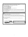
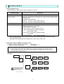
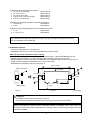
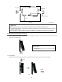
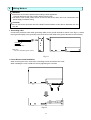
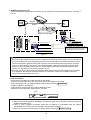
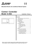
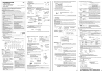
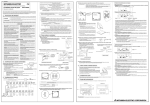
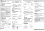
Mitsubishi Electric Air-conditioner Network System
Central Controller
Model: GB-50A
Installation Manual
Contents
1. Safety Precautions to be Observed without Fail ..........1
2. Confirmation of Parts .................................................3
3. Product Feature .........................................................4
4. System Diagram ........................................................5
5. Installation Method ....................................................7
1. Part prepared at site ..............................................7
2. Allowable length of M-NET transmission lines.........7
3. Installation method ................................................8
6. Wiring Method .........................................................11
1. Grounding cable. .................................................11
2. Cover removal and installation .............................11
3. M-NET transmission line ......................................12
4. LAN connection ...................................................12
7. Initial setting ............................................................13
1. How to set the IP address with dip switches .........14
2. Setting of the service switch.................................14
8. Test Run .................................................................15
1. Collective operation ON/OFF ...............................15
2. Service LED display.............................................15
9. Example for System Configuration............................16
1. To control a K control model ................................16
2. To use system controllers on multiple units ..........16
10. External Input/Output Usage Method ......................16
1. External signal input function ...............................16
2. External signal output function .............................18
Before using the controller, please read this Installation Manual carefully to ensure correct
operation. Store this Installation Manual in a location that is easy to find.
This manual describes the installation of the central controller and wiring to the air conditioner. Refer to the
installation manual of the air conditioner. Carefully read item “1 Safety precautions to be observed without fail”
before installing the unit.
1
Safety Precautions to be Observed without Fail
* Hazards and levels of danger that can occur due to incorrect handling are classified by the following symbols.
WARNING
Incorrect handling can result in death, serious injury, etc.
CAUTION
Incorrect handling can result in injury or damage to the building or its contents.
* After reading this manual, keep in a handy place. When removing or repairing the unit, give this manual to the
installer. When the user changes, also give to the new user.
WARNING
Ask your dealer or technical
representative to install.
If incorrect installation is done by a customer, it
may cause an electric shock, fire, etc.
Securely install the controller according
to the installation manual.
If installation is not correct, it may cause an
electric shock, fire, etc.
Securely install in a place which can
withstand the weight of the controller.
If it is not enough, the unit may fall and
cause an injury.
The electric work should be perform by
authorized personal according to the
installation manual.
Any lack of electric circuit or any deficiency
caused by installation may result in an
electric shock or fire.
Securely connect the wiring using the
specified cables and fix them so that the
stress from the cables is not applied to
the terminal connection sections.
If connection or fixing is not reliably
connected, it may cause heat generation, a
fire, etc.
Do not move and re-install the unit by
yourself.
If installation is not correct, it may cause an
electric shock, fire, etc.
Ask your dealer or technical representative.
This appliance must be earthed (grounded).
Make sure to install a protect earth(PE)/grounding line .
Do not connect the PE (grounding) line to gas or water
pipes, lightning conductors or telephone grounding lines.
Improper grounding may cause an electric shock.
Never modify or repair by yourself.
If the controller is modified or a repair is not
correct, it may cause an electric shock, fire,
etc.
Consult your dealer if repairs are necessary.
CAUTION
Do not install the controller in a place
where flammable gas could leak.
If gas leaks and collects around the unit, it
may cause a fire or explosion.
Do not install this controller in a place
where the ambient temperature exceeds
40ºC (104ºF) or drops below 0ºC (32ºF),
also do not install in a place where it is
exposed to direct sunlight.
It may cause a deformation or malfunction.
Do not use this controller in an
abnormal environment.
If the controller is used in a place where there is
much oil (including machine oil), steam or
sulfide gas, the performance of the controller
may deteriorate or parts may be damaged.
Do not install this controller in a place
where steam is generated such as
bathroom, kitchen, etc.
Avoid placing where water condenses on
the walls. It may cause an electric shock or
malfunction.
1
CAUTION
Perform wiring so the tension is not
applied.
If tension is applied, it may cause
disconnection, heat generation or a fire.
Do not install this controller in a place
where an acid or alkaline solution,
special spray, etc. is used frequently.
It may cause an electric shock or
malfunction.
Do not wash this controller with water.
It may cause an electric shock or
malfunction.
Do not press the switches with sharp
objects.
It may cause an electric shock or
malfunction.
Use specified wires corresponding to
the current capacity for wiring.
Otherwise it may cause power leakage, heat
generation or fire.
Do not connect an AC power source to the
M-NET terminal blocks of this device.
It may cause a breakdown or fire.
Do not touch the PCB (Printed Circuit
Board) with your hand or a tool. Also do
not get dirt on the PCB.
It may cause a fire or malfunction.
Do not touch the switches with wet hands.
It may cause an electric shock or
malfunction.
2
2
Confirmation of Parts
*Please confirm that in addition to this Installation Manual the following items are enclosed in the box.
No.
Part name
Qty.
1
Central controller
1
2
L-fitting
2
3
M3 (8mm (5/16in)) round head screw (for fixation of the fitting described in 2 above)
4
4
DIN rail attachment
2
5
M3 (6mm (1/4in)) round head screw (for fixation of the attachment described in 4 above)
8
6
Installation manual (this book)
1
7
Installation book
1
* The screws for installing to the control panel are not included. (M4 screws)
* In addition to the parts above, a power supply unit for transmission line, which supplies the power to the central controller
through the transmission line, must be purchased. When R410A, however, the power can be supplied also from the
R410A outdoor unit.
Unit that supplies the
power to GB-50A
PAC-SC50KUA
R410A outdoor unit
(connected to the
transmission line for
central control)
Outdoor unit other than
described above
(connected to
the indoor/outdoor
transmission line)
The number of
connectable GB-50A
2 units *1
Remarks
● When only one GB-50A unit is connected
Up to three other system controllers can be
connected to the transmission line for central
control
(Up to three ON/OFF remote controllers, up to six
system remote controllers, up to six schedule
timers, or up to six group remote controllers can
be connected.)
● When two GB-50A units are connected
No other system controllers can be connected.
Replace CN41 (power-supply switch connector) with
CN40 on only one outdoor unit.
Connectable number of indoor units will decrease by
4 units.
Connectable number of indoor units will decrease by
4 units.
1 unit
1 unit
*1: Cannot be connected to the different transmission line for central control in the different system.
* Use PAC-SC50KUA (power supply unit) when “Charge” function is used, or multiple outdoor units are connected. Connect
only the M-NET terminal (TB2) on PAC-SC50KUA to the M-NET terminal on GB-50A.
3
3
Product Feature
1. Specification
Item
Interface
Environmental condition
Dimensions
Weight
Installation Environment
Contents
M-NET
:DC30V/24V;0.13/0.15A
External I/O :DC12V or 24V (External power supply)
Ethernet
:10Base-T
Temperature
Operating range 0 to 40ºC / 32 to 104ºF
Storage range -20 to 60ºC / -4 to 140ºF
Humidity
30~90%RH (No condensation)
130(H) x 250(W) x 38 (D) mm/51/8 (H) x97/8 (W) x 11/2 (D)in
1.1kg/21/2lb
In the control panel box (indoor)
*This unit is installed and used in a business office or equivalent environment.
2. Outline dimensions
38 (11/2)
Main body
130 (51/8)
POWER LAN LINK/ACT
123456
250 (97/8)
Fig. 3-1
Unit:mm(in)
L-fittings
20 (25/32)
10 (25/64)
20 (25/32)
Fig. 3-2
4
Unit:mm(in)
4
System Diagram
PAR-20/21MAA (MA)
Note
●This diagram does not show
the AC power supply wiring.
Only the configuration for the
transmission line is shown.
* Address setting for each M-NET device (The address cannot be duplicated.)
* The K transmission converter (PAC-SC25KAA) and OA processing unit (LOSSNAY) are not included in
systems shipped to North America (USA & Canada).
Indoor unit
Outdoor unit
BC controller/OS controller
* OS: Subsidiary Outdoor unit
K control side remote controller
M-NET remote controller
MA remote controller
OA processing unit/LOSSNAY
K transmission converter
Address setting method
Set the indoor unit you want to make them master unit in
the same group to the minimum address, and sequentially
set the indoor unit address in the same group.
Address
1-50
Min. indoor unit address in same refrigerant system + 50
Outdoor unit address in same refrigerant system + 1
However, for Sub-BC controller, minimum indoor unit
address that connects the local refrigerant piping + 50.
Same address as indoor unit master unit
Set to the minimum indoor unit master address in the
same group + 100.
Address setting is unnecessary.
After setting all the indoor units, set an arbitrary address.
Min. address of K control indoor unit + 200
51-100
52-100
5
1-50
101-200
1-50
201-250
NOTE
* The following precautions will apply when using the K transmission converter (model: PAC-SC25KAA)
and controlling the M-NET model and K control model with the same controller.
Refer to the K transmission converter installation manual for details.
1) Central controller address
Always set the controller address to “00”.
(Refer to section 7 Initial setting .)
2) Central controller function selects
Always set the No.3 function selects of the controller to "ON".
(Refer to section 7 Initial setting .)
3) Indoor unit address
Set all M-NET model indoor units from the No.1 unit, and then set the K control model addresses.
Indoor unit No.1 unit – M-NET indoor unit max. address->K control indoor unit min. address – 50.
4) K control model group No.
The min. indoor address No. of that group becomes the group No. (Same for K control side local
remote controller.)
NOTE
* This system controller is designed as a main controller, not as a sub controller.
● Main system controller (main SC)
The main system controller is designed to control all units including the units that other system
controllers control. When there is only one system controller in a system, it will become the main
system controller. Group setting or interlock setting can be made only with the main system controller.
● Sub system controller (sub SC)
The sub system controller is designed to have its control area to be controlled by the main
system controller.
Control area of main SC
Control area of sub SC
Group
Group
Group
This system controller is designed as a main controller,
so it cannot be controlled by a main SC (such as
Gateway).
6
5
Installation Method
1. Parts prepared at site
Please prepare the following parts before installation of the unit.
Preparation parts
Unit fixing screw
Protective earth cable
(Ground cable)
Specification
M4 screw x 4pcs (when using L-fittings) *1
Use sheathed vinyl cord or wire.
Wire type : Wire should not be lighter than ordinary PVC sheathed flexible
cord IEC 60227
(designation 60227 IEC 53)
Wire size : 0.75mm2 to 2mm2 (AWG 18 to 14)
Wire color : The color combination green/yellow
Round terminal
M4 screw size terminal (used for protective earth cable)
Transmission cable
Type of the cable; Sheathed vinyl cords or cable which comply with the
following specifications or equivalent.
● CPEVΦ1.2mm to Φ1.6mm
● CVVS 1.25mm2 to 2mm2 (AWG 16 to 14)
*CPEV: PE insulated PVC jacketed shielded
communication cable
*CVVS: PVC insulated PVC jacketed shielded
control cable
PE: Polyethylene
PVC: Polyvinyl chloride
*1: When installing DIN rail, prepare 35mm(1.38inch) DIN rail. Mounting screws for DIN rail must be
also procured separately.
Applicable DIN rail types (IEC 60715/DIN 60715): TH35-7.5Fe, TH35-7.5Al
2. Allowable length of M-NET transmission lines
● Maximum length of M-NET transmission
=500m/1640 ft *1
● Maximum power feeding length
=200m/656 ft *1
NOTE
* 1: Not including the remote control cables up to 10m (32 ft) in length. If the remote control
cable exceeds 10m (32 ft), the excess must be added to the total length in order to avoid
exceeding the maximum length.
Example
ℓ1
Outdoor
unit
GB-50A
ℓ3
ℓ2
Indoor
Indoor
ℓ4
Remote controller
Power
supply
unit
Indoor
Indoor
ℓ5
Indoor
ℓ7
ℓ6
M-NET transmission line
(Centralized control line)
M-NET transmission line
(Indoor control line)
Indoor
Outdoor
Indoor
ℓ8
Indoor
Remote controller
7
Indoor
1) Maximum length of M-NET transmission
1 L2+L3+L4+ℓ1+ℓ2+ℓ3 (ℓ4)
2 L2+L3+L4+ℓ1+ℓ5
3 L2+L3+L5+ℓ6+ℓ7 (ℓ8)
4 ℓ3 (ℓ4)+ ℓ2+ℓ1+L4+L5+ℓ6+ℓ7 (ℓ8)
5 ℓ5+ℓ1+L4+L5+ℓ6+ℓ7 (ℓ8)
=500m/1640 ft
=500m/1640 ft
=500m/1640 ft
=500m/1640 ft
=500m/1640ft
2) Maximum power feeding length for the indoor control line
1 ℓ1+ℓ2+ℓ3 (ℓ4)
=200m/656 ft
2 ℓ1+ℓ5
=200m/656 ft
3) Maximum power feeding length for the centralized control line
1 L1+L2
=200m/656 ft
2 L1+L3+L4 (L5)
=200m/656 ft
NOTE
If the remote control cable (ℓ4, ℓ8) do not exceed 10m (32 ft) in length, the length for ℓ4, ℓ8 may
not be considered to the total length.
3. Installation method
Central controller GB-50A is not waterproof.
Installation methods for the central controller GB-50A are shown below.
Method1: Horizontal installation using L-fittings
Attach two L-fittings to GB-50A using the supplied screws (Fig.5-1), then install GB-50A (Fig.5-2).
GB-50A shall be installed in a control panel box (steel: thickness 1mm (3/64 in) or more).
Please prepare the control panel box in consideration with installation space as shown in the Fig.5-2.
(Install in an area capable of withstanding a 1.1 kg (2 1/2 lb) load.)
Install GB-50A horizontally as shown in the Fig.5-2.
290 (11 13/32)
M4
Total of 4 screws
20 (13/16)
M3
20 (13/16) *1
20 (13/16)
(Both sides)
50 (2)
Fig.5-1
Fig.5-2
unit:mm(in)
CAUTION
● L-fittings must be fixed at two points on the unit.
● The unit with L-fittings must be fixed at four points to prevent the unit from falling.
NOTE(*1)
When connecting the protective earth cable after GB-50A is installed, leave some space for
mounting screws. When there is little space for mounting screws, connect the grounding wire before
GB-50A is installed.
8
Method2: Vertical installation using L-fittings
After removing the screws on GB-50A, attach two L-fittings to GB-50A using the supplied screws (Fig.5-3),
then install GB-50A (Fig.5-4).
GB-50A shall be installed in a control panel box (steel : thickness 1mm (3/64 in) or more).
Please prepare the control panel box in consideration with installation space as shown in the Fig.5.4.
(Install in an area capable of withstanding a 1.1 kg (2 1/2 lb) load.)
Install GB-50A vertically as shown in the Fig.5-4.
(Reference) When GB-50A is installed inside the control board, it is recommended that it be installed after
the wiring work, so that the installation becomes easy.
M3
M3 (8(5/16))
20 (13/16)
L-fitting
NOTE(*1)
When performing wiring
work after GB-50A is
installed, leave some space
for mounting screw.
20 (13/16)
20 (13/16)*1
290 (11 13/32)
(Both sides)
20 (3/16)
Fig.5-3
Fig.5-4
unit:mm(in)
CAUTION
● L-fittings must be fixed at two points on the unit.
● The unit with L-fittings must be fixed at four points to prevent the unit from falling.
Method3: Installation using DIN rail
GB-50A can be attached to DIN rail (35mm(1.38inch)).
Attach DIN rail attachment to GB-50A using the supplied screws (Fig.5-5), then install GB-50A (Fig.5-6).
GB-50A shall be installed in a control panel box (steel : thickness 1mm (3/64 in) or more).
Please prepare the control panel box in consideration with installation space as shown in the Fig.5-6.
(Install in an area capable of withstanding a 1.1 kg (2 1/2 lb) load.)
Install GB-50A vertically as shown in the Fig.5-6.
Left view
Rear view
M3 (6(1/4))
Total of 8 screws
Top
Under
Fig.5-5
9
unit:mm(in)
20 (13/16)
20 (13/16)
20 (13/16)
DIN rail (35mm)
50 (2)
Fig.5-6
unit:mm(in)
CAUTION
● DIN rail attachment must be fixed at four points on the unit using two attachments.
● To secure the strength, screw pitch of 200mm(7.88inch) or less is required when DIN rail is fixed
on the control board.
● Use GB-50A in a place where it receives no vibrations. Use studs as necessary to fix GB-50A.
Installation and de-installation on DIN rail
1) Installation
Put the upper side of attachment on DIN rail, and push the bottom of the unit in the direction of the arrow
shown in the figure below.
CAUTION
● Check that the attachment is fixed securely to
the DIN rail.
Fig.5-7
2) De-installation
Push the unit downwards, and pull it in the direction of the arrow shown in the figure below.
Step1
Step2
Fig.5-8
10
6
Wiring Method
WARNING
● All electric work must be performed according to local regulations.
Improper electrical work may result in electric shock or fire.
● Be sure to shut off the power source of the unit and the all other unit to be connected to the
power supply unit before wiring.
CAUTION
●Do not connect the AC power line to the M-NET terminal blocks of this device. Otherwise, the unit
may fall.
1. Grounding cable
Connect the protective earth cable (grounding cable) to the ground terminal as shown in the Fig.6-1. Attach
the ring terminal (M4) to the grounding cable, and connect the cable to the ground terminal on the unit body.
Protective
earth cable
(Grounding cable)
Cable color
: The color combination green / yellow
Fig. 6-1
2. Cover Removal and Installation
When removing the cover, remove the 2 mounting screws and remove the cover.
When installing the cover, install the cover by tightening the 2 screws.
Fig.6-2
11
3. M-NET transmission line
Connect the M-NET transmission line to the A, B (non-polarity) and S (shield) terminal block, as shown in
Fig. 6-3.
PACSC50
KUA
Outdoor
unit
GB-50A
M-NET
TB7
TB2
M-NET
M-NET terminal block
A B S
Shield
Shield
Vinyl tape etc. (*1)
M-NET transmission A, B line
(Non-polarity DC24V)
Vinyl tape etc. (*1)
M-NET transmission A, B line
(Non-polarity DC24V)
(*1) Insulate the shielded wire with
vinyl tape except for the end where it
is connected to the terminal screw.
Fig.6-3
CAUTION
DC power to the M-NET transmission line is supplied from either the power supply unit PAC-SC50KUA
or R410A outdoor unit. When supplying the power from R410A outdoor unit to the transmission line for
central control (TB7), disconnect the male connector from the female power supply switch connector
(CN41: no power supply) and connect it to the female power supply switch connector (CN40: power
supply) on only one of the outdoor units. For further details, refer to the transmission manual of the
outdoor unit. Not doing so may cause unit failure or fire.
Securely connect the wiring using the specified cables and fix them so that the stress from the cables
is not applied to the terminal connection sections. If connection or fixing is not reliably connected,
it may cause heat generation, a fire, etc.
4. LAN connection
Connect the LAN cable to the LAN connector of this device.
● Procure the LAN cable at the site, and use an enhanced category 5UTP cable.
● For a description of the IP address setting method, refer to section 7 Initial setting . .
● LAN is 10 BASE-T Specification.
● The maximum wiring length from HUB to GB-50A is 100m.
● GB-50A is connected to the monitoring PC via HUB.
LAN
NOTE
● Perform the LAN wiring before installation, and wire up to the unit by the same method as wiring of
M-NET transmission line.
● When a LAN is already connected, decide the IP address by consultation with the system
administrator and connect the LAN port after changing the IP address.
● Space for the connector and wiring is required. Refer to section 5 Installation method .
12
7
Initial Setting
Initial setting steps
Step 1: IP address setting
Step 2: License number registration
Step 3: Group setting
Step 4: Other settings
Step 5: Test run
*License must be registered before use.
Note
● Initial setting can be set with either the initial setting tool or the initial setting web through LAN. More
functions can be set with the initial setting web. The license is not registered at factory shipment,
and monitor or operation cannot be performed on the air conditioner.
In this section, the functions that can be initialized using this unit are described. Refer to the
operation manuals for the initial setting tool or the initial setting web for more information.
● The format in which the Web page address for each GB-50A is expressed on the Initial Setting
Web, as well as the default setting user name and password are shown below.
http:// [IP address of the GB-50A]/g-50/ administrator.html
Note: For example, type “http://192.168.1.1/g-50/administrator.html” if the GB-50A IP
address is [192.168.1.1].
User
Default
user name
Default
password
Maintenance user
initial
init
The function list of GB-50A main body, the Initial Setting Tool, and the Initial Setting Web is shown below.
Initial
Setting Tool
√
√
Initial Setting
Web
√
√
Function selection
√
√
Group registration
√
√
√
√
√
√
Items
This unit
M-NET address setting
IP address setting
√
(simple setting)
Registration of interlocked
operation with the
ventilation unit
Service switch
Other settings
Remarks
The default value is 0.
*The settings of the simple setting
have the priority over other settings.
Presence/absence of K transmission
converter connection, local operation
prohibition setting, and external input
mode
√
13
Available functions vary depending on
the tool.
1. How to set the IP address with dip switches
IP addresses between 192.168.1.1 and15 can be set using the 4-pin dip switch on SW2.
Set this switch before turning the power on.
1
2
3
4
Contents (IP address)
Address that is set with Initial Setting Tool or
OFF OFF OFF OFF
Initial Setting Web
(Default IP address setting is 192.168.1.1
(Factory setting))
OFF OFF OFF ON Starts from 192.168.1.1
(Inside the cover)
OFF OFF ON OFF Starts from 192.168.1.2
OFF OFF ON
ON Starts from 192.168.1.3
OFF ON OFF OFF Starts from 192.168.1.4
OFF ON OFF ON Starts from 192.168.1.5
OFF ON
ON OFF Starts from 192.168.1.6
OFF ON
ON
ON OFF OFF ON Starts from 192.168.1.9
ON
OFF
1 2 3
ON Starts from 192.168.1.7
ON OFF OFF OFF Starts from 192.168.1.8
SW 2
ON OFF ON OFF Starts from 192.168.1.10
ON OFF ON
4
ON
ON Starts from 192.168.1.11
ON OFF OFF Starts from 192.168.1.12
ON
ON OFF ON Starts from 192.168.1.13
ON
ON
ON OFF Starts from 192.168.1.14
ON
ON
ON
ON Starts from 192.168.1.15
NOTE
● When setting IP addresses with the Initial Setting Web or the Initial Setting Tool, set all four
dipswitches on SW2 to OFF.
● If the IP address of GB-50A is forgotten, check the IP address that is registered on the
monitoring PC (Web or TG-2000A). GB-50A can be started by changing the setting of SW2 on
GB-50A IP address and using an arbitrary fixed IP address as a temporary IP address. It is
recommended to paste a sticker with the IP address on that unit, so that the IP address of
GB-50A is available at all times.
2. Setting of the service switch
The switches must be OFF for normal use. The switch setting change works when the power is turned on next
time.
SW 1
ON
OFF
1 2 3
4
Not to be used
1
2
Contents
OFF
OFF
ON
OFF
-
Setting is prohibited.
OFF
ON
-
Setting is prohibited.
Start up with the normal
mode
Remarks
*This setting is for normal use.
*The software can be updated with the
ON
ON
Start up with the update
mode
normal mode. If the update fails, or the
software does not work properly, use
this setting to update the software
again.
*SW1-3 and SW1-4 are always OFF.
14
8
Test Run
1. Collective operation ON/OFF
* After setting the group or interlocked setting, confirm that the controller has started up, and then perform a
test run.
* It may take approx. 10 minutes for local remote controller operation to be enabled after the power is turned
ON. In this case, press the collective ON/OFF switch on the controller to enable immediate local remote
controller operation.
(Test run procedure)
1. Turn ON the Power to the controller and all the units.
2. When the LED1 on the main unit turns OFF from ON, press SW3. The units registered in the same
group will start a group operation. When the group operation starts, the LED2 on this turns ON.
3. Confirm the run state during the test run.
4. When each unit has been confirmed, stop the unit with the controller or local remote controller.
* Refer to the installation manual for the connected indoor unit for details on the test run method.
* The test run mode cannot be selected with this collective
ON/OFF switch (SW3). The operation mode will be the
current operating mode.
SW 3
Note
● Use the local remote controller to change the mode to the “Test run” mode.
● The operation mode other than the “Test run” mode can be selected on the Web browser.
● The format in which the Web page address for each GB-50A is expressed on the Web browser, as
well as the default setting user name and password are shown below. For further detail, refer to the
manual for Web browser.
http:// [IP address of the GB-50A] / administrator.html
Note: For example, type “http://192.168.1.1/administrator.html” if the GB-50A IP address is [192.168.1.1].
Default
user name
administrator
User
Managers
Default
password
admin
2. Service LED display
The LED display the status of the unit as follows.
LED No.
Power supply
LED
LAN
LAN
LED1
LED2
LED3
LED4
LED5
LED6
Items
Powering status
LAN LINK
LAN ACT
Start-up
Operation ON/OFF
Error
(not defined)
(not defined)
M-NET communication
(transmission)
POWER LAN LINK/ACT
Power supply
LED
LAN
Contents
ON
: Power is supplied
ON : During LINK
Flicker: During communication
ON
: Start-up not completed
ON
: 1 or more units are ON
Flicker: Error occurred on 1 or more units
Flicker : During communication
123456
LED1-6
15
/ OFF: Power is cut off
/ OFF: No LINK
/ OFF: No communication
/ OFF: Start-up completed
/ OFF: All OFF
/ OFF: Normal state
/ OFF: No communication
9
Example for System Configuration
1. To control a K control model
GB-50A
● Set GB-50A address to “000” when a K transmission
000
Converter is connected. Always set to the master system
(Main system controller)
Controller when the address is “000”.
● When using a group setting for the K control model, set
Only the indoor unit that belongs to that group.
● Set the min. indoor unit address in the group for the K
control model group No.
The K transmission converter address is “K control model
address + 200”. Set the address to K transmission converter
main body, and register it to GB-50A using the Initial Setting
Web or the Initial Setting Tool.
● Set the master system controller function select
No.4 to “OFF” (operation prohibit transmission valid)
When the K transmission controller is connected.
2. To use system controllers on multiple units
● Make the initial setting such as group setting or interlock
setting using the Initial Setting Web or the Initial Setting
Tool on GB-50A.
● Set one system controller that is allowed to
send operation prohibition within a system.
M-NET
20 indoor units
Group 1 to Group 10
221
20 indoor units (for control)
Group 21 to Group 38
K transmission converter
(Model: PAC-SC25KAA)
Power supply unit
(Model PAC-SC50KUA)
50 Indoor units
Group 1 to 20)
GB-50A
000
(Main system controller)
ON/OFF remote
controller 201
(Sub system controller)
Power supply unit
(Model PAC-SC50KUA)
10
External Input/Output Usage Method
1. External signal input function
* External signal input requires the external I/O adapter (Model: PAC-YG10HA) sold separately.
CN2
(1) External input
Emergency stop/normal, run/stop and prohibit/enable of local remote controller operation can be
controlled for all air conditioners being controlled by using a voltage (DC12V or DC24V) contact signal
from an external source. (Select with the function select setting using the Initial Setting Web or the Initial
Setting Tool.)
No.
1
2
External signal input function
Do not use external input signal (factory
setting)
Execute emergency stop/normal with level
signal
Function
No.6 No.7
OFF OFF
OFF
ON
Perform ON/OFF with level signal
ON
OFF
Perform ON/OFF, prohibit/enable with pulse
signals
ON
ON
3
4
16
Remarks
The local remote controller ON/OFF operations, and
the controller ON/OFF operation and prohibit/enable
change operations will be prohibited during
emergency stop.
The local remote controller ON/OFF operations, and
the controller ON/OFF operations and
prohibit/enable change operations will be prohibited.
Set the pulse width while the contact is ON to 0.5 to
1 sec.
(2) Level signal and pulse signal (DC12V or DC24V)
(3) External input specification
CN2
No.5
No.6
No.7
No.8
No.9
Lead wire
Orange
Yellow
Blue
Gray
Red
Emergency stop/normal level
signal
ON/OFF,
level signal
ON/OFF, prohibit/enable pulse signal
Emergency stop/normal input
Not used
Not used
Not used
External DC source “+”
ON/OFF input
Not used
Not used
Not used
ON input
OFF input
Local remote controller operation prohibit input
Local remote controller operation enable input
(A) For level signal
1 When the emergency stop/normal signal is selected, the status will change from normal to emergency
stop when the external input signal contact changes from OFF to ON, and will change from emergency
stop to normal when the contact changes from ON to OFF. Emergency stop signal will bring the air
conditioners to stop, and canceling the emergency stop will not automatically reset these units. To go
back to the previous operation status, they must be manually turned back on.
2 When the ON/OFF signal is selected, the status will change from OFF to ON when the external input
signal contact changes from OFF to ON, and will change from ON to OFF when the contact changes
from ON to OFF.
(B) For pulse signal
1 Even if the ON signal is input during ON, the status will remain ON.
2 If the local remote controller is prohibited, the ON/OFF operation mode and temperature setting
operations by the local remote controller will be prohibited.
3 Set the pulse width (contact ON time) to 0.5 to 1 sec.
(4) Recommended circuit example
1 The contact relay, DC power source, extension cable, etc, must be prepared separately at the site.
2 The connection cable can be extended up to 10m (32 ft). (Use a 0.3mm2 (AWG 22) or larger wire.)
3 Strip the extra cable near the connector, and securely insulate the exposed section with tape, etc.
17
2. External signal output function
* External signal output requires the external I/O adapter (Model: PAC-YG10HA) sold separately.
(1) External output
When one or more air conditioners are running, the “ON” signal will be output and if a malfunction occurs
in one or more air conditioners, the “Malfunction” signal will be shown.
(2) External output specifications
CN2
No.1
No.2
No.3
No.9
Lead wire
Green
Black
Brown
Red
Details of each terminal
Common (External ground)
ON/OFF
Malfunction/normal
Common (External power supply) (*1)
1 “ON” signal and “Malfunction”
signal will both be shown.
(3) Recommended circuit example
Use Z1 and Z2 relays having the following specifications.
Operation coil
Rated voltage
: DC12V, DC24V
Power consumption
: 09.W or less
(*1) Prepare a power supply separately according to the relay
being used. (DC12V or DC24V)
(*2) Always insert a diode on both ends the relay coil.
1 Each element will turn on while ON operation or a malfunction occurs.
2 The connection cable can be extended up to 10m (32 ft).
3 The relays, lamps, diodes and extension cables, etc, must be prepared separately at the site.
18
0