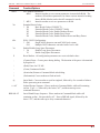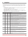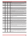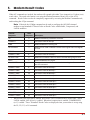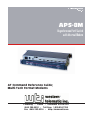
1
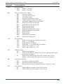
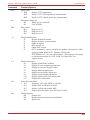
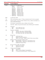
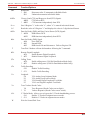
WTI Part No.: 13203
Rev. A
APS-8M
Asynchronous Port Switch
with Internal Modem
AT Command Reference Guide;
Multi-Tech Format Modems
5 Sterling · Irvine · California 92618-2517
(949) 586-9950 · Toll Free: 1-800-854-7226
Fax: (949) 583-9514 · http://www.wti.com
Table of Contents
1.
Introduction . . . . . . . . . . . . . . . . . . . . . . . . . . . . . . . . . . . . . . . . . . . . . . 1-1
2.
Communicating with the Internal Modem . . . . . . . . . . . . . . . . . . . . . . . . . . . . . 2-1
3.
AT Command Set. . . . . . . . . . . . . . . . . . . . . . . . . . . . . . . . . . . . . . . . . . . 3-1
4.
S-Registers . . . . . . . . . . . . . . . . . . . . . . . . . . . . . . . . . . . . . . . . . . . . . . 4-1
5.
Modem Result Codes . . . . . . . . . . . . . . . . . . . . . . . . . . . . . . . . . . . . . . . . . 5-1
i
1.
Introduction
WTI’s APS-8M Asynchronous Port Switch allows reliable, high-speed connections between PCs,
modems, and other devices using dissimilar baud rates, parity, and flow control. The APS-8M supports
communication at speeds up to 115.2 Kbps, and features full RTS/CTS hardware handshaking and a
33.6K internal modem. Lightening-swift data throughput and full flow control make the APS-8M the
perfect data switch for today’s high speed communications applications.
In addition to the APS-8M's Menu Driven configuration functions, the internal modem will also accept
AT commands. This document describes the AT command set for the Multi-Tech format modem, and
lists the function of each command.
If necessary, the AT commands can be used to select advanced modem configuration parameters. AT
commands can be sent directly to the modem, or added to the user defined initialization string via Port 8
Configuration Menu.
Note: For information on general APS-8M installation, configuration, and operation
procedures, please refer to the APS-8M User's Guide (WTI P/N 13202).
1-1
2.
Communicating with the Internal Modem
In order to invoke AT commands manually, you must communicate directly with the APS-8M's internal
modem or include commands in the Port 8 Configuration Menu's "Init String" field. Please note that
although APS-8M Port 8 is the internal modem port, any APS-8M port can also be configured for
connection to an external modem.
To communicate with the APS-8M's internal modem, proceed as follows:
1. Access the APS command mode as described in Section 5.1 in the APS-8M User's Guide.
Notes:
• If you log on to the APS-8M using a Port Password (rather than the Supervisor Password),
you will only be able to connect to Port 8 if your password allows access to that port. The
Supervisor Password always allows access to Port 8.
• To access the internal modem's command mode from a remote location, you must first dial
into an external modem installed at one of the other RS232 ports, and then proceed as
described below. The internal modem command mode cannot be accessed via a remote
connection to the internal modem.
2. When the "APS>" command prompt appears, type /C 8 and press [Enter] to connect to the
internal modem port (Port 8)..
3. When the connection is established, the APS-8M will respond with a message that reads
"Connected: 08", and lists the port name and currently selected disconnect command.
4. To terminate the connection to the internal modem, invoke the currently selected disconnect
command (Default = ^X)
2-1
3.
AT Command Set
This section describes the AT command set. Note the following:
· Type commands in either upper or lower case. Do not use a combination of upper and lower case
characters.
· Use the Backspace key to delete errors.
· All commands begin with the AT prefix, and are invoked by pressing [Enter] (Carriage Return). The
only exceptions are the A/ command (Repeat previous command) and +++ (Exit to on-line command
mode).
· The maximum command length is 40 characters. This does not include the AT prefix, Carriage
Returns, or spaces.
· Defaults are marked with an asterisk (*).
Command
AT
Function/Options
Attention Command. Required prefix for most command strings except A/, A: and
Escape Codes.
A
Forced Answer. Answers call, even if no ring is present.
A/
Re-execute Last Command. Used mainly to redial. Does not require the AT prefix or a
Carriage Return to execute.
A:
Continuous Redial. Redials last number dialed until answered.
$
Calling Card Symbol. When placed in the dialing string, this character allows the modem
to detect AT&T's "Call Card" tones to access the user's calling card when originating an
on-line connection.
$An
Discard / Buffer Data during Auto-Reliable Linking.
$A0
Discards data during auto-reliable linking.
$A1
Buffers data during auto-reliable linking.
#An
Selects Initial Handshake
* #A0
Detect all speeds during handshake.
#A1
14.4K bps only if V.32Bis, 9600 bps only if V.32.
#A2
Detect high speed only (14.4K, 9600, 4800 bps).
#A3
Disable high speed detect (2400, 1200, 300 bps).
&Bn
Transmit Buffer Size
* &B0
Normal transmit buffer size (2K).
&B1
Reduced transmit buffer size (512).
&BSn
Transmit Block Size
&BS0
Maximum transmit block size of 64 characters.
* &BS1
Maximum transmit block size of 256 characters
(MNP mode) / 128 characters (LAP-M mode).
3-1
APS-8M ; Modem AT Command Reference Guide
Command
Bn
Function/Options
CCITT Mode / Bell Mode
* B0
V.21 for 300 bps operation (CCITT Mode).
B1
300 bps operation (Bell Mode).
$BAn
Speed Conversion
* $BA0
Enable Speed Conversion (Baud Adjust Off).
$BA1
Disable Speed Conversion (Baud Adjust On).
&Cn
Data Carrier Detect (DCD) Signal.
&C0
Forced DCD signal ON.
* &C1
Normal DCD operation (required by most software).
&C2
DCD drops upon disconnect (follows Register S24).
&C4
Reset modem when DCD drops.
&CDn
Ds
AT Command Set
Cleardown on Disconnect.
* &CD0
Execute cleardown on disconnect.
&CD1
Do not execute cleardown on disconnect.
Dial Command. Dial the telephone number "s", where s may include up to 60 characters
or T, P, R, comma and ; characters.
DsNd
Store Telephone Number, where "s" is the phone number and "d" is the desired
directory number.
&Dn
Data Terminal Ready (DTR) signal.
&D0
Ignore DTR.
&D1
Modem returns to command mode.
* &D2
Normal DTR.
&D3
DTR drop causes modem to reset to default parameters.
$Dn
Data Terminal Ready (DTR) Dialing.
* $D0
Disable DTR Dialing.
$D1
Enable DTR Dialing.
%DFn
V.34 Line Probe Data Format.
* %DF0
V.34 Line Probe Data in Graph Format.
%DF1
V.34 Line Probe Data in Table Format.
%DPn
Read Line Probe Information.
* %DP0
Do not read Line Probe Information from DSP during handshaking.
%DP1
Read Line Probe Information from DSP during handshaking.
>DTn
Detect DTMF tones.
* >DT0
Disable modem detecting of DTMF tones.
>DT1
Enable modem detecting and reporting of DTMF tones
when off-hook.
En
Set Modem Command Mode Echo.
E0
Disable echoing of command mode characters.
* E1
Enable echoing of command mode characters.
3-2
APS-8M ; Modem AT Command Reference Guide
Command
AT Command Set
Function/Options
$EBn
Eleven Bit Mode.
* $EB0
Disable 11 bit mode.
$EB1
Enable 11 bit mode.
&En
Error Correction / Flow Control.
&E0
No Error Correction.
* &E1
V.42 Auto-reliable mode.
&E2
V.42 Reliable mode.
&E3
No modem-initiated flow control.
* &E4
CTS/RTS modem-initiated flow control.
&E5
XON/XOFF modem initiated flow control.
* &E6
Disable XON/XOFF pass-through.
&E7
Enable XON/XOFF pass-through.
&E8
Disable Enq/Ack pacing.
&E9
Enable Enq/Ack pacing.
* &E10
Disable Normal Mode flow control.
&E11
Enable Normal Mode flow control.
&E12
Disable pacing.
* &E13
Enable pacing.
&E14
Disable Data Compression.
* &E15
Enable Data Compression.
%En
Escape Method.
%E0
Disable escape sequence (modem won't escape).
* %E1
Enable +++ AT Method
%E2
Enable BREAK AT Method.
%E3
Enable both +++AT and BREAK AT Methods.
%E4
Disable "OK" response to +++AT.
%E5
Enable "OK" response to +++AT.
#Fn
Fallback Settings.
#F0
Disable on-line fallback.
#F1
Enable on-line fallback; Fallback from 33.6K to 4800 bps when on-line
(increments of 2400 bps).
* #F2
Enable on-line fallback and fall forward. Fallback from 33.6K to
4800 bps. Fall forward if line improves (increments of 2400 bps).
&Fn
Load Factory Defaults.
&F0
Load factory defaults from ROM.
* &F8
Reads factory defaults when &F is issued.
&F9
Read parameters stored in nonvolatile memory when &F is issued.
$Fn
Link Fallback.
$F0
Disable fallback to normal connect if CR received.
* $F1
Enable fallback to normal connect if CR received.
3-3
APS-8M ; Modem AT Command Reference Guide
Command
&Gn
AT Command Set
Function/Options
Guard Tone.
* &G0
Disable CCITT guard tones.
&G1
Enable CCITT 550 Hz guard tone (international).
&G2
Enable CCITT 1800 Hz guard tone (international).
Hn
Disconnect (Hang Up).
H0
Hangs up (goes on hook).
H1
Goes off hook.
$Hn
Help Screen.
$H1
Help Screen #1.
$H2
Help Screen #2.
$H3
Help Screen #3.
In
Modem Identification.
I0
Request modem ID number.
I1
Request firmware revision number.
I2
Model of modem.
I3
MTS internal use.
I5
Output DSP version.
I9
The I9 command is a query to display the modem's characteristics when
operating within Windows 95. Entering ATI9 invokes
ZPX 28800 FAX CT on your video monitor. (The response to this query
reveals that this modem is a ZPX, 28.8K, FAX and Class Two
capable device.)
Ln
Display Parameters.
L0
Display Stored Phone Numbers.
L5
Display all current operating parameters.
L6
Display all current S-Register values.
L7
Display additional parameters.
L8
Display current on-line diagnostics.
L9
Display signal strength information.
L10
Display signal to noise ratio information.
L11
Display noise information.
#Ln
Select Detection Phase.
* #L0
Negotiates V.42 mode (MNP or LAP-M).
#L1
Enables MNP and disables LAP-M.
#L2
Enables LAP-M and disables MNP.
#L3
Disables detection phase, goes directly to LAP-M.
Mn
Modem Speaker.
M0
Speaker Off.
M1
Speaker On until connection is established.
M3
Speaker On.
3-4
APS-8M ; Modem AT Command Reference Guide
Command
AT Command Set
Function/Options
$MBn
Modem (Telco Port) Baud Rate.
$MB75
CCITT V.23 mode.
$MB300
300 bps on-line.
$MB1200
1200 bps on-line.
$MB2400
2400 bps on-line.
$MB4800
4800 bps on-line.
$MB9600
9600 bps on-line.
$MB14400 14,400 bps on-line.
$MB19200 19,200 bps on-line.
$MB28800 28,800 bps on-line.
* $MB33600 33,600 bps on-line.
&M0
Asynchronous Mode.
Nd
Dial stored telephone number "d" (Do not include the letter D in this command.)
NdNe
Number Linking. If the first number dialed (d) is busy, another stored number (e)
may be dialed automatically
O
Exit Modem Command Mode and go to Modem On-Line Mode.
P
Pulse Dial. Modem will pulse dial a number entered following the P command.
&Pn
Pulse Ratio.
&P0
* &P1
#Pn
Parity for 11 Bit Mode.
#P0
No Parity when using 11 Bit Mode ($EB1).
#P1
Odd Parity when using 11 Bit Mode ($EB1).
#P2
Even Parity when using 11 Bit Mode ($EB1).
Qn
Result Codes.
* Q0
Send Result Codes.
Q1
Suppress Result Codes (Quiet).
Q2
Dumb Answer Mode. Suppress Result Codes in Answer Mode.
&Qn
Rn
&Rn
Selects 60/40 pulse ratio.
Selects 67/33 pulse ratio.
Reliable, Compressed and LAP-M Result Codes.
* &Q0
Enable Reliable / Compressed / LAP-M Result Codes.
&Q1
Disable Reliable / Compressed / LAP-M Result Codes
(Standard AT Result Codes).
Reverse to Answer Mode After Dialing.
* R0
Disable Reverse Mode.
R1
Enable Reverse Mode.
Clear to Send (CTS) Signal.
&R0
Normal CTS
* &R1
Forces CTS on in Modem Command Mode.
&R2
CTS forced ON until disconnect. Follows Register S24.
3-5
APS-8M ; Modem AT Command Reference Guide
Command
$Rn
AT Command Set
Function/Options
Retransmit.
* $R0
$R1
Disconnect after 12 retransmits in Reliable Mode.
Unlimited retransmits in Reliable Mode.
&RFn
Clear to Send (CTS) and Request to Send (RTS) Signals.
&RF0
CTS follows RTS.
* &RF1
CTS functions independently from RTS.
Sr=n
Sets S-Register "r" to the value "n", where "n" is entered in decimal format.
Sr?
Reads the value of S-Register "r" and displays the value in 3-digit decimal format.
&SFn
Data Set Ready (DSR) and Data Carrier Detect (DCD) Signals.
* &SF0
DSR follows DCD.
&SF1
DSR functions independently from DCD.
&Sn
Data Set Ready (DSR) Signal.
&S0
Force DSR On.
* &S1
Normal DSR.
&S2
DSR forced ON until disconnect. Follows Register S24.
T
Tone Dial. Modem will tone dial numbers following the T command.
&Tn
Remote Digital Loopback.
&T4
Enable Remote Digital Loopback.
* &T5
Disable Remote Digital Loopback.
$Tn
Calling Tones.
&T0
Enable calling tones (1300 Hz Data/Modem Mode Only).
* &T1
Disable calling tones (1300 Hz Data/Modem Mode Only).
#Tn
Trellis Encoding.
#T0
Disable Trellis Encoding.
* #T1
Enable Trellis Encoding.
Un
Loopback.
U0
U1
U2
U3
Vn
Terse/Verbose Result Codes.
V0
Terse Response (Result Codes sent as digits).
* V1
Verbose Response (Result Codes sent as words).
#Vn
V.32terbo Mode. Allows user to bypass the V.32terbo handshaking process.
#V0
Enables V.32terbo in originate/answer modes.
* #V1
Disables V.32terbo in originate/answer modes.
W
V.54 Analog Loop Originate Mode.
V.54 Analog Loop Answer Mode.
V.54 Remote Digital Loopback Test Mode.
V.54 Local Digital Loopback Test Mode.
Wait for Second Dial-Tone.
3-6
APS-8M ; Modem AT Command Reference Guide
Command
&Wn
AT Command Set
Function/Options
Save Modem Parameters.
&W0
Instructs modem to save current parameters in nonvolatile RAM. The
modem will load these parameters for future sessions instead of reading
factory ROM defaults (unless the &F command is issued).
* &W1
Instructs modem to not save parameters to RAM.
Xn
Extended Result Codes.
* X0
Basic Result Codes (CONNECT).
X1
Extended Result Codes (CONNECT 9600).
X2
Extended Result Codes, Enable Dialtone Detect.
X3
Extended Result Codes, Enable Busy Detect.
X4
Extended Result Codes, Enable Dialtone Detect and Busy Detect.
#Xn
XON / XOFF Configuration.
* #X0
Single XOFF character sent until XON level returns.
#X1
Multiple XOFF characters sent after buffer level is full.
Yn
Enable/Disable Long Space Disconnect.
* Y0
Disable Long Space Disconnect.
Y1
Enable Long Space Disconnect.
Z
Reset Modem. All configuration parameters are reset to default values.
,
(Comma) Pause. Creates pause during dialing. The duration of the pause is determined
by Register S6.
/
(Slash) Pause for 125 MS.
:
(Colon) Continuous Redial.
;
(Semicolon) Return to Command Mode after dialing.
!
(Exclamation) Causes modem to flash on-hook.
@
Quiet Mode. Causes modem to wait for ringback, followed by five seconds of silence
before processing next command.
+++AT
BREAK AT
In-band Escape Sequence. Places modem in Command Mode, while still remaining
on-line. Type +++ followed by the letters "AT", and then enter up to ten
command characters.
Out-of-Band Escape Sequence. Places modem in Command Mode while still
remaining on-line. Not preceded by AT. Enter a BREAK signal, followed by the
letters "AT", and then enter up to sixty command characters.
3-7
4.
S-Registers
The S-Registers are used to store modem configuration parameters, display modem status, and initiate
modem test and diagnostic functions. In order to invoke commands to change or display the contents of
the S-Registers, you must first access the modem command mode as described in Section 2. Note the
following:
· View Status Screen: To display the modem status screen, which lists the current values assigned to
most S-Registers, type ATL6 and press [Enter].
· View S-Register Value: To display the value currently assigned to a specific S-Register, type
ATSr? and press [Enter] (Where r is the desired S-Register).
· Change S-Register Value: To change the value assigned to an S-Register, type ATSr=n and press
[Enter] (Where r is the desired S-Register, and n is the desired value).
Register
Range
Default
Function
S00
0 - 255
0
Auto Answer. Sets the number of rings that will elapse before the modem answers in
Auto Answer Mode. When set to 0, Auto Answer is disabled.
S01
0 - 255
0
Ring Count. Counts the number of rings that
have occurred.
S02
0 - 127
43
Escape Character Code. Stores the ASCII decimal code for the escape code character.
The default value of 43, defines the escape code character as "+" (plus sign).
S03
0 - 127
13
Carriage Return Character. Stores the ASCII code for the Carriage Return character.
The default value is 013 (normal carriage return).
S04
0 - 127
10
Line Feed Character. Stores the ASCII decimal code for the Line Feed character. The
default value is 010 (normal line feed).
S05
0 - 127
8
Backspace Character. Stores the ASCII decimal code for the Backspace character.
The default value is 008 (normal backspace character).
S06
2 - 255
2
Wait for Dial Tone. Sets the amount of time (in seconds) that the modem will wait
between going off-hook and beginning dialing.
S07
1 - 255
45
Wait for Carrier. Sets the number of seconds the modem will wait for a carrier signal
from a remote modem. If a carrier is not received, the modem will hang-up and send
the NO CARRIER message. Often used to select a longer duration when the modem
is originating an international connection.
S08
0 - 255
2
Pause Time. Determines the duration (in seconds) for the pause that is generated
when the pause character (,) is inserted into a dialing command line.
S09
1 - 225
6
Carrier Detect Response Time. Determines the length of time (in tenths of a second)
required for the modem to recognize the incoming carrier signal from the remote
modem, and turn on the DCD.
S10
1 - 255
7
Carrier Loss Disconnect Delay Time. Sets the length of time (in 100 Ms increments)
that the modem will wait after loss of carrier before hanging up. If this value is set
lower than the value contained in S09, a loss of carrier will always result in
disconnection.
4-1
APS-8M ; Modem AT Command Reference Guide
S-Registers
Register
Range
Default
Function
S11
1 - 255
70
Tone Dialing; Tone Spacing and Duration. Sets the duration and spacing (in
milliseconds) between DTMF (touch tone) dialing characters.
S12 to S16
---
---
Not Used.
S17
0 - 250
250
Change Break Time. Defines the break time (space) (in 10 Ms increments) to local
PC.
S18 to S23
---
---
Not Used.
S24
0 - 255
20
PBX/CBX Disconnect Drop Time for DSR/CTS/DCD. Defines the DSR/CTS/DCD
drop out time in 50 mSec increments. The default value of "20 equals one second.
S25
0 - 255
0
DTR Dropout Time. Defines DTR dropout time in 100 mSec increments. The default
value of "0" equals 50 Msec.
S26
0 - 255
0
Failed Password Attempts. Counts the number of failed password attempts.
S27 to S28
---
---
Not Used.
S29
1 - 255
20
Local Inactivity Timer. Defines the amount of idle time (in minutes) that can elapse
between AT commands after the SETUP password has been entered.
S30
0 - 255
0
Inactivity Timer. Sets the length of time (in minutes) that the modem will stay on-line
before disconnecting when no data is
sent or received.
S31
---
---
Not Used.
S32
0 - 255
20
Time Elapse for Escape Sequence. Determines the period of time (in seconds) that the
modem will wait for a <CR> to be entered during escape sequence execution.
S33
---
---
Not Used.
S34
0 - 60
10
Buffer Length of Command Mode (After On-line Escape Sequence). Sets the buffer
length (in ASCII characters) of the command mode after on-line escape sequence.
S35
---
---
Not Used.
S36
0 - 255
0
Time Between DTR Inactive and Modem Off- Hook. Sets the time (in seconds)
between DTR inactive (low) and the modem going off-hook. When Register S36=0,
the DTR Busy-out feature is disabled.
S37
0 - 255
5
Time Between DTR Active and Modem On-Hook. Sets the time (in seconds) that will
elapse between the DTR signal becoming active and the modem going on-hook (not
busy).
S38 to S47
---
---
Not Used
S48
33, 31, 28,
26, 21, 19,
16, 14, 12,
9, 4 or 0
0
Program V.34 Connect Speeds. Defines which speed modem connects within V.34
mode scope (e.g., S48=21 means maximum connect speed is 21.6K). This register
compensates for line conditions that will not support higher V.34 speeds (e.g., 33.6K,
31.2K, 28K, 26.4K, 24K, and etc.). The default value of 0 specifies a connection
attempt at 33.6K.
4-2
5.
Modem Result Codes
When AT commands are invoked, the modem will respond with either Terse (numeric) or Verbose (text)
result codes. The result code format is set using the Modem Parameters Menu (/M), or the ATVn
command. Result Codes can also be completely suppressed by accessing the Modem Command mode,
and invoking the ATQn command.
Note: If desired, the AT&Qn command can be used to configure the APS-8M's internal
modem to send standard AT Result Codes or Result Codes with Reliable, Compressed, and
LAP-M modifiers.
Verbose
Response
Terse
Response
Description
OK
0
Modem Successfully executed a command.
CONNECT
1
Connection made at 300 bps.
RING
2
Modem detected an incoming call.
NO CARRIER
3
Modem lost or could not detect a remote carrier signal within the Register
S7 time.
ERROR
4
Modem found an error in the command line.
CONNECT 1200
5*
Connection made at 1200 bps. *
NO DIALTONE
6
Modem did not detect a dial tone within 5 seconds after going off-hook.
BUSY
7
Modem detected a busy signal.
NO ANSWER
8
Five seconds of silence was not detected when using the @ command in
the ATD command.
CONNECT 2400
9*
Connection made at 2400 bps. *
CONNECT 4800
11*
Connection made at 4800 bps. *
CONNECT 9600
12*
Connection made at 9600 bps. *
CONNECT 14400
13*
Connection made at 14400 bps. *
CONNECT 19200
19*
Connection made at 19200 bps. *
CONNECT 21600
21*
Connection made at 21600 bps. *
CONNECT 24000
24*
Connection made at 24000 bps. *
CONNECT 26400
26*
Connection made at 26400 bps. *
CONNECT 28800
28*
Connection made at 28800 bps. *
CONNECT 31200
31*
Connection made at 31200 bps. *
CONNECT 33600
33*
Connection made at 33600 bps. *
*
When MNP error correction is enabled, RELIABLE (or R) is added to these result codes. When
LAP-M enabled, LAP-M (or L) is added. When data compression is enabled, COMPRESSED
(or C) is added. These "Extended" Result Codes are displayed when your modem is set-up using
the X1, X2, X3, or X4 command.
5-1
APS-8M ; Modem AT Command Reference Guide
Modem Result Codes
Customer Service
Customer Service hours are from 8:00 AM to 5:00 PM, PST, Monday through Friday. When calling,
please be prepared to give the name and make of the unit, its serial number and a description of its
symptoms. If the unit should need to be returned for factory repair it must be accompanied by a Return
Authorization number from Customer Service.
WTI Customer Service
5 Sterling
Irvine, California 92618
Local Phone: (949) 586-9950
Toll Free: 1-888-280-7227
Fax: (949) 457-8138
Email: [email protected]
Trademark and Copyright Information
WTI and Western Telematic are trademarks of Western Telematic, Inc. All other product names
mentioned in this publication are trademarks or registered trademarks of their respective companies.
Information and descriptions contained herein are the property of Western Telematic, Inc. Such
information and descriptions may not be copied disseminated or distributed without the express written
consent of Western Telematic, Inc.
© Copyright Western Telematic, Inc. 2001
November 2001
Part Number: 13203 Revision: A
5-2