1
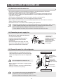
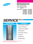
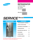
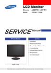
REFRIGERATOR
Model Name : RB195/215B*
(Model Code)
REFRIGERATOR
PRODUCT FEATURE
● Reversible Door
● Auto Ice-Maker
● Fridge Wire Box
For the latest parts information, Please access to our service web site (http://itself.sec.samsung.co.kr)
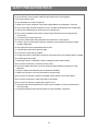
WARNING
IMPORTANT SAFETY NOTICE
The service guide is for service men with adequate backgrounds of
electrical, electronic, and mechanical experience. Any attempt to repair a
major appliance may result in personal injury and property damage. The
manufacturer or dealer cannot be responsible for the interpretation of this
information.
SAMSUNG ELECTRONICS AMERICA, INC.
Technical Service Guide
Copyright ⓒ2005
All rights reserved. This service guide may not be reproduced in whole or in
part in any form without written permission from the SAMSUNG ELECTRONICS
Company.
2
Contents
1. INSTALLATION
∙∙∙∙∙∙∙∙∙∙∙∙∙∙∙∙∙∙∙∙∙∙∙∙∙∙∙∙∙∙∙∙∙∙∙
4
2. NOMENCLATURE∙∙∙∙∙∙∙∙∙∙∙∙∙∙∙∙∙∙∙∙∙∙∙∙∙∙∙∙∙∙∙∙∙∙4
3. PRODUCT SPECIFICATIONS ∙∙∙∙∙∙∙∙∙∙∙∙∙∙∙∙∙∙∙∙∙∙∙∙∙∙∙5
4. ELECTRICAL PART SPECIFICATIONS & STANDARD∙∙∙∙∙∙∙∙∙∙∙∙∙5
5. WARRANTY INFORMATION
∙∙∙∙∙∙∙∙∙∙∙∙∙∙∙∙∙∙∙∙∙∙∙∙∙∙∙7
6. INTERIOR VIEWS AND DIMENSIONS∙∙∙∙∙∙∙∙∙∙∙∙∙∙∙∙∙∙∙∙∙∙8
7. REFRIGERATION CYCLE AND COOL AIR CIRCULATION ROUTE
∙∙∙∙10
8. MECHANICAL DISASSEMBLY ∙∙∙∙∙∙∙∙∙∙∙∙∙∙∙∙∙∙∙∙∙∙∙∙∙∙12
9. REVERSIBLE THE DOOR SWING∙∙∙∙∙∙∙∙∙∙∙∙∙∙∙∙∙∙∙∙∙∙∙∙19
10. INSTALLATION OF THE WATER LINE ∙∙∙∙∙∙∙∙∙∙∙∙∙∙∙∙∙∙∙∙∙24
11. TEMP CONTROL &OPERATION FUNCTIONS ∙∙∙∙∙∙∙∙∙∙∙∙∙∙∙∙25
12. OPERATION PRINCIPLES BY PARTS OF CIRCUIT ∙∙∙∙∙∙∙∙∙∙∙∙∙46
13. DIAGNOSTICS
∙∙∙∙∙∙∙∙∙∙∙∙∙∙∙∙∙∙∙∙∙∙∙∙∙∙∙∙∙∙∙∙∙∙54
14. ILLUSTRATED PARTS CATALOG∙∙∙∙∙∙∙∙∙∙∙∙∙∙∙∙∙∙∙∙∙∙∙∙71
15. OTHER ∙∙∙∙∙∙∙∙∙∙∙∙∙∙∙∙∙∙∙∙∙∙∙∙∙∙∙∙∙∙∙∙∙∙∙∙∙∙∙81
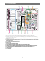
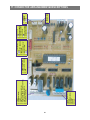
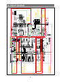
16. PCB DIAGRAM
∙∙∙∙∙∙∙∙∙∙∙∙∙∙∙∙∙∙∙∙∙∙∙∙∙∙∙∙∙∙∙∙∙∙84
17. CONNECTOR ARRANGEMENT&DESCRIPTIONS
18. BLOCK DIAGRAM
∙∙∙∙∙∙∙∙∙∙∙∙∙85
∙∙∙∙∙∙∙∙∙∙∙∙∙∙∙∙∙∙∙∙∙∙∙∙∙∙∙∙∙∙∙∙86
19. CIRCUIT DIAGRAM
∙∙∙∙∙∙∙∙∙∙∙∙∙∙∙∙∙∙∙∙∙∙∙∙∙∙∙∙∙∙∙87
20. WIRING SCHEMATIC
∙∙∙∙∙∙∙∙∙∙∙∙∙∙∙∙∙∙∙∙∙∙∙∙∙∙∙∙∙∙88
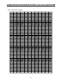
21. TEMP TO RESISTANCE OF SENSOR &MICOM PORT VOLTAGE
3
∙∙∙∙89
1. INSTALLATION
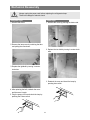
1) To protect refrigerator in movement
Use padded hand truck from side only.
2) Remove all protective tape and pad from the refrigerators.
Connect power cord. Adjust the clearance between the doors.
3) Temperature controls and preset in the factory for
recommended settings.
The refrigerator should runs smoothly and lower the
temperature gradually.
4) Once the refrigerator temperature is sufficiently low
It is recommended to store foods in the refrigerator.
It takes a few hours to reach the preset temperatures.
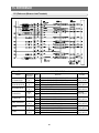
2. NOMENCLATURE
2005 Models
R
B 19 5
B
S SB
/
XAA
Company Name
COLOR ; SB-STAINLESS PLATINUM, SW-SNOW WHITE
VQ-BISQUE GLOSSY, BB-BLACK
S : W2-PJT
Buyer : BEST BUY
OPTION ; BETTER
Capacity ; 19:19CU,FT 21:21CU,FT
B - BOTTOM MOUNTED FREEZER (BMF)
Product ; R - REFRIGERATOR
Label Location
4
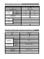
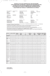
3. PRODUCT SPECIFICATIONS
Model
RB195BSSW, RB195BSSB, RB195BSVQ, RB195BSBB RB215BSSW, RB215BSSB, RB215BSBB, RB215BSVQ
Type
BMF 2 Door
Temperature control
Electronic control
Total
18.7
20.4
Freezer
5.9
6.5
Refrigerator
12.8
13.9
32.3 X 28.3 X 69.9
32.3 X 30.3 X 69.9
Net Capacity
3
(ft )
Net dimension
(W X D X H)
Foam
Cabinet insulation
CYCLO-PENTANE
Door insulation
CYCLO-PENTANE
Cabinet
A.B.S
Door
A.B.S
Liner
227
Net weight(Ib)
241
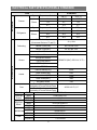
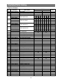
4. ELECTRICAL PART SPECIFICATIONS & STANDARD
STANDARD
ITEM
Model
RB195BSSW, RB195BSSB, RB195BSVQ, RB195BSBB
RB215BSSW, RB215BSSB, RB215BSBB, RB215BSVQ
Rated Voltage
115V
Frequency
60HZ
Compressor
Model
MK172C-L2U
Starting type
RSCR
Refrigerant
R134a
Oil Charge
Freol α-10c(Ester), 265cc
Freezer
Split Fin & Tube Type
Refrigerator
Split Fin & Tube Type
Evaporator
Condenser
Forced & Natural Convection Type
Dryer
Molecular Sieve XH-9
Capillary tube
ID0.82 X L3000
Earth screw
BSBN(Brass screw)
Door switch
AC125V 1.4A(SSD-6D)
5
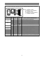
ELECTRICAL PART SPECIFICATIONS & STANDARD
ITEM
STANDARD
Temperature
Type
Freezer
F-Sensor
Type
Refrigerator
R-Sensor
Temperature Selection
ON(℉)
OFF(℉)
–14℉
–12.0℉
–16.0℉
–2℉
0℉
–4℉
8℉
10℉
6℉
Temperature Selection
ON(℉)
OFF(℉)
34℉
36℉
32℉
38℉
40℉
36℉
46℉
48℉
44℉
First Defrost Cycle
(Concurrent Defrost of F and R)
Defrosting
4hr ±10min
Defrost Cycle(FRE)
Min. 12hrs, Max. 22Hrs
Defrost Cycle(REF)
Min. 6hrs, Max. 11Hrs
Pause Time
10±2min
Freezer-Sensor
Refrigerator-Sensor
Sensor
FRE Evap-Sensor
THERMISTOR (502AT), SPEC:5.0KΩ AT 77℉
Electrical parts
REF Evap-Sensor
Ambient TEMP-Sensor
Heater
Defrost Heater(FRE)
242W
Drain Heater(FRE)
52W
Defrost Heater(REF)
120W
Drain Heater(REF)
38W
Ice-maker Heater
10W
Thermal-Fuse for preventing
overheating of Freezer Defrost-Heater
AC250V 10A 77±5˚C
Fuse
Thermal-Fuse for preventing
overheating of Freezer Defrost-Heater
Capacitor
RUNNING
RSCR 250VAC, 12㎌
MODEL
4TM437RHBYY-53
Over-Load
Protector
TEMP. ON
130±5
TEMP. OFF
69±9
STARTINGMODEL
J531Q33E100M200-2
RELAY
OPERATION
10±20%
FRE.
IS3210-SNP6D
REF.
MOTOR-FAN
IS3208-SNP6H
CIRCUIT
IS3208-SCH6A
FRE(INCANDESCENT)
110V-130V/15W X2
LAMP
REF(INCANDESCENT)
110V-130V/30W
6
5. WARRANTY INFORMATION
7
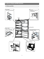
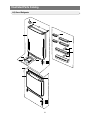
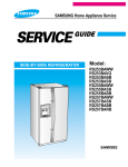
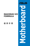
6. Interior Views and Dimensions
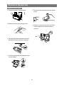
6-1) Shelves and Bins
• Deli drawer
• Door Bin
Pull it out to disassemble.
Push it up and slide it out
to disassemble.
Light
•
•
•
• Gallon Bin
• Glass Shelf
•
Pull it out until its stop
Tilt down and slide it out.
•
• Vegetable Drawer
•
•
• Freezer Drawer
• Ice trays
8
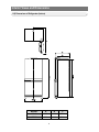
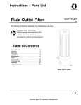
Interior Views and Dimensions
6-2) Dimensions of Refrigerator (Inches)
MODEL
A
B
C
RB195
RB215
24.3
28.3
57.8
26.3
30.3
59.8
9
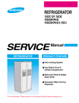
7. Refrigeration Cycle and Cool Air Circulation Route
7-1) Refrigerant Route in Refrigeration cycle
Compressor → Sub condenser → Cluster pipe → Hot pipe → Dryer → Capillary tube
→ R-Evaporator → F-Evaporator → Accumulator → Suction pipe → Compressor
10
Refrigeration Cycle and Cool Air Circulation Route
7-2) Cool Air Circulation
11
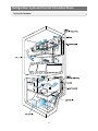
8. Mechanical Disassembly
Refrigerator Disassembly
Control Panel
∙∙∙∙∙∙∙∙∙∙∙∙∙∙∙∙∙∙∙∙∙∙∙∙∙∙∙∙∙∙∙∙∙∙∙∙∙∙∙∙
13
Refrigerator Light ∙∙∙∙∙∙∙∙∙∙∙∙∙∙∙∙∙∙∙∙∙∙∙∙∙∙∙∙∙∙∙∙∙∙∙∙∙∙ 14
Freezer Light
∙∙∙∙∙∙∙∙∙∙∙∙∙∙∙∙∙∙∙∙∙∙∙∙∙∙∙∙∙∙∙∙∙∙∙∙∙∙∙∙
Evaporator Cover in the Refrigerator
∙∙∙∙∙∙∙∙∙∙∙∙∙∙∙∙∙∙∙∙∙∙∙∙∙∙
15
∙∙∙∙∙∙∙∙∙∙∙∙∙∙∙∙∙∙∙∙∙∙∙∙∙∙∙∙∙
16
∙∙∙∙∙∙∙∙∙∙∙∙∙∙∙∙∙∙∙∙∙∙∙∙∙∙∙∙∙∙∙∙∙
17
Evaporator Cover in the Freezer
Evaporator in the Freezer
14
Evaporator in the Refrigerator
∙∙∙∙∙∙∙∙∙∙∙∙∙∙∙∙∙∙∙∙∙∙∙∙∙∙∙∙∙∙
17
Machine Compartment & Electric Box ∙∙∙∙∙∙∙∙∙∙∙∙∙∙∙∙∙∙∙∙∙∙∙∙∙∙18
12
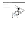
Mechanical Disassembly
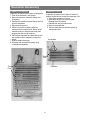
Control Panel
1. Remove the screws.
2. Pull out the control panel.
3. Disconnect the wire connector.
13
Mechanical Disassembly
Warning
Always unplug the power cord before replacing the refrigerator lamp.
There is the danger of electric shock.
Refrigerator Light
Freezer Light
1. Remove the screw.
1. Remove the cover by pressing the bottom tab.
2. Remove the lamp cover by unlocking the tabs
and pulling the cover down.
2. Replace the two bulb by turning it counter-clock
wise.
3. Replace the lightbulb by turning it counterclockwise.
3. Reattach the cover and check the lamp by
pressing door switch.
4. After replacing the bulb, reattach the cover
and the screw it again.
5. Plug the power cord in and check the lamp by
pressing the R-door switch.
14
Mechanical Disassembly
Evaporator Cover in the Refrigerator
6. Disconnect the wire connector.
1. Remove all shelves and drawers from the
refrigerator.
2. Pull out the screw caps with a small flat-blade
screwdriver.
3. Remove 6 Phillps screws from the cover.
■Ductwork of the evaporator fan assembly.
4. Unlock the 2 tabs with a flat-blade screwdriver
on each side of the bottom cover.
5. Remove the evaporator cover by pulling out
from the bottom of the evaporator cover.
15
Mechanical Disassembly
Evaporator Cover in Freezer
5. Disconnect wire connector from the top-left
corner.
1. Remove all drawers from the freezer.
2. Remove screws (2) from the support rail.
6. Remove 2 screws from the rear cover of the
freezer evaporator and unlock the tabs to
remove it.
2 screws
3. Pull down the holder of the support rail and
disconnect the wire connector to remove it.
①
②
4. Unlock the tabs around the evaporator cover
from the buttom.
②
③
①
16
Mechanical Disassembly
Evaporator in Refrigerator
Evaporator in Freezer
Evaporator is located in the bottom of refrigerator.
1. Take off the ductwork in refrigerator.
2. Disconnect the wire connector.(Heater and
Thermistor)
3. Desolder the capillary tube and the suction line
from the evaporator.
4. Remove the evaporator.
5. With a file, score the capillary tube just
upstream of the soldered point. Break off the
soldered section to help prevent solder from
plugging the tube during soldering.
6. Place a new evaporator and braze the suction
and capillary tube to evaporator using silver
solder.
7. Install a replacement dryer.
8. Evacuate and recharge the system using
reasonable procedures.
Evaporator is located in the bottom of freezer to
produce cold air driven across the evaporator coils.
1. Take off the ductwork in Freezer.
2. Disconnect the wire connector (Heater,
Bimental, and Thermistor).
3. Desolder the inlet and outlet tubes.
4. Remove the evaporator.
5. Take the same steps to seal the system as
mentioned earlier.
Accumulator
Thermal
Fuse
Thermal
Fuse
Thermistor
Thermistor
17
Mechanical Disassembly
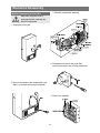
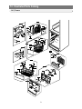
Machine Compartment & Electric Box
3. Mechine compartment assembly
Make sure the power cord is
unplugged before replacing any
Warning electric components.
1. Unplug the power cord.
4. Disassemble the electric box cover after
removing the screws with a Phillips screwdriver.
2. Remove the screws of the compartment cover.
Slide it up and take out from the refrigerator.
5. Electric box assembly
18
9. REVERSING THE DOOR SWING
Read these instructions completely and carefully
- IMPORTANT NOTES
Warning
Unplug the refrigerator from its electrical outlet.
Empty all door guards / racks.
1. If you want to change the door direction, call 1-800-SAMSUNG.
2. Read the instructions carefully before starting.
3. Handle parts carefully to avoid scratching paint.
4. Set screws down by their related parts to avoid using them in the wrong places.
5. Provide a non-scratching work surface for the doors. (ex : blanket)
6. During door reversing, refrigerator should not be stained with oil.
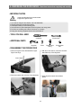
- TOOLS YOU WILL NEED
screwdriver
10 inch wrench
- ADDITIONAL PARTS
Hinge Mid
Screw
Compression
Fitting
Compression
Nut
- DISASSEMBLY THE FRIDGE DOOR
1. After removing the screw, disassemble the Upper
Right Cover Hinge.
3. With the 10 inch wrench, remove the four bolts
that hold the top of the refrigerator.
Cover Hinge
2. Disconnect electric wire on the top of the refrigerator.
4. Apart Hinge from electric wire as below
picture.
19
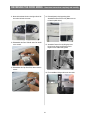
REVERSING THE DOOR SWING
5. Disassemble the fridge door by lifting it upward.
Be careful not to drop and scratch the fridge door.
Read these instructions completely and carefully
- ASSEMBLY OF FREEZER DOOR
8. After removing the screw, disassemble the
Cover Hinge(left) and the Hinge(right).
Hinge
Cover Hinge
- DISASSEMBLY OF FREEZER DOOR
9. Move the hardware found on the right side
of the cabinet to the left and vice-versa.
6. After removing the screw and two bolts,
disassemble Hinge Mid.
Hinge Mid
10. After removing the left and right side
screws, disassemble the Grommet, Stopper
Door and Stopper-Mid of the right bottom of
freezer-door.
7. Disassemble the Freezer Door by lifting it upward.
Be careful not to drop and scratch the Freezer
door.
Stopper Mid
Stopper Door
Grommet
20
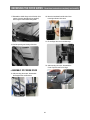
REVERSING THE DOOR SWING
11. Move the hardware found on the right side of the
door to the left and vice-versa.
12. Disassemble the Door S/W with tools. Be careful
not to scratch.
Read these instructions completely and carefully
14. Re-install parts in their opposing sides.
Assemble the Door S/W as it is. (Make sure not
to insert it upside down)
15. Assemble Freezer Door by fitting the lower
hinge into the hinge grommet hole. Don't
forget to insert washer with grease.
Door S/W
Washer
13. Disassemble the Cap Door S/W, Sleeve and the
screws.
16. Fix the additional Hinge mid into the door hole.
Cap Door S/W
Additional
Hinge mid
Sleeve
21
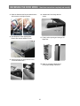
REVERSING THE DOOR SWING
17. Reinstall the middle hinge on the left side of the
cabinet. (Use the alternative hinge supplied)
Don't forget to insert washer with grease.
Read these instructions completely and carefully
20. Move the hardware from left side of door
to the right side and vice-versa.
Washer
21. Fit the fridge door into the middle hinge.
18. Confirm opening and closing of the door.
22. After removing the screw, dissemble the
Cover-Cap Door and Cover Hinge.
- ASSEMBLY OF FRIDGE DOOR
19. After removing the screws, disassemble
the Stopper Door and Grommet.
Cover Hinge
Grommet
Cover Cap Door
Stopper Door
22
REVERSING THE DOOR SWING
Read these instructions completely and carefully
23. Place the Grommet and Cap wire taken from the
left connector on the right connector.
26. Assemble the Cover Hinge with the
screws.
Cover Hinge
Grommet
Cap wire
24. Re-install parts in their opposing sides.
Electric wires must be sealed in covers.
27. Finally, confirm opening and closing of the
fridge door.
25. After securing the top hinge with the screws,
connect the electric wire.
28. Make any necessary adjustments to
insure proper sealing of the doors.
23
10. INSTALLATION OF THE WATER LINE
10-1) Before You Install the water line
• This water line installation is not warranted by the refrigerator or icemaker manufacturer. Follow these
instructions carefully to minimize the risk of expensive water damage.
• Banging pipes (water banging in the pipes) in house plumbing can cause damage to refrigerator parts and
lead to water leakage or flooding. Call a qualified plumber to correct the problem before installing the water
supply line to the refrigerator.
• To prevent burns and product damage, do not hook up the water line to the hot water line.
• Do not install the icemaker tubing in areas where temperatures fall below freezing.
• When using any electrical device (such as a power drill) during installation, be sure the device is insulated or
wired in a manner to prevent electric shock.
• All installations must be in a accordance with local plumbing code requirements.
NOTE
- Water line Kit and water filter are not covered by Samsung Warranty and manufacturer(or dealer, installer)
of them should be responsible for the defect and all the loss caused by water filter & water line kit .
- Filter should be replaced according to manufacturer (or dealer)'s instruction.
- To order additional water filters, please contact the manufacturer (or dealer) of the filter.
10-2) Connecting to water supply line
- Shut off the main water supply line and turn the
Ice maker to the off position.
- Locate the nearest cold drinking water line.
- Follow the instructions in the ice maker
installation kit.
- After connecting the water supply with water
filter, turn on water supply and flush 4 or more
gallons into a bucket to clear the water filter
1. Cold Water line
2. Pipe Clamp.
3.Copper (or Plastic) line
4.Compression Nut
5.Compression Sleeve
6.Shut Off Valve
7.Packing Nut.
10-3) Connect the water line to the refrigerator
- Slip the compression nut through the plastic tube.
- After inserting the compression nut into plastic tube,
tighten the compression nut onto 1/4” compression
fitting.
Household water line
Compression
Nut (Purchased)
Ferrule
(Purchased)
Compression
fitting (Provided)
Do not overtighten the compression nut.
NOTE
- Slip the compression ferrule and nut on copper(or plastic)
tubing as shown.
Tighten the compression nut onto the compression fitting.
- Turn water on and check for any leakege.
Compression
Nut (Provided)
Refrigerator
NOTE
- You can purchase the necessary parts through BEST BUY.
- Waterline must be connected to drinkable water only
- Compression fitting and nut will be given inside of ice bucket.
24
11. Temp Control &Operation Functions
11-1) DISPLAY DESIGN ∙∙∙∙∙∙∙∙∙∙∙∙∙∙∙∙∙∙∙∙∙∙∙∙∙∙∙∙∙∙∙∙26
11-2) Temp Control Function∙∙∙∙∙∙∙∙∙∙∙∙∙∙∙∙∙∙∙∙∙∙∙∙∙∙∙∙∙∙26
11-3) Super Freeze Function and Super Cool Functions ∙∙∙∙∙∙∙∙∙∙∙∙∙∙∙27
11-4) Ice Off Function
∙∙∙∙∙∙∙∙∙∙∙∙∙∙∙∙∙∙∙∙∙∙∙∙∙∙∙∙∙∙∙∙∙29
11-5) Child Lock Function
∙∙∙∙∙∙∙∙∙∙∙∙∙∙∙∙∙∙∙∙∙∙∙∙∙∙∙∙∙∙∙29
11-6) Buzzer Alarm Function ∙∙∙∙∙∙∙∙∙∙∙∙∙∙∙∙∙∙∙∙∙∙∙∙∙∙∙∙∙30
11-7) Machine Compartment F-Fan Motor Delay Function ∙∙∙∙∙∙∙∙∙∙∙∙30
11-8) Ice Maker Function (Only applicable to Model with the Auto Ice Maker function)
∙∙∙31
11-9) Defrost Function ∙∙∙∙∙∙∙∙∙∙∙∙∙∙∙∙∙∙∙∙∙∙∙∙∙∙∙∙∙∙∙∙∙35
11-10) Test Function∙∙∙∙∙∙∙∙∙∙∙∙∙∙∙∙∙∙∙∙∙∙∙∙∙∙∙∙∙∙∙∙∙∙35
11-11) Function when the power is applied for the first time. ∙∙∙∙∙∙∙∙∙∙∙36
11-12) Power Compensation Function
11-13) Self Diagnosis Function
∙∙∙∙∙∙∙∙∙∙∙∙∙∙∙∙∙∙∙∙∙∙∙∙37
∙∙∙∙∙∙∙∙∙∙∙∙∙∙∙∙∙∙∙∙∙∙∙∙∙∙∙∙37
11-14) Power Compensation Function
∙∙∙∙∙∙∙∙∙∙∙∙∙∙∙∙∙∙∙∙∙∙∙∙40
11-15) Option Setting Function (EEPROM)
11-16) Option Table
∙∙∙∙∙∙∙∙∙∙∙∙∙∙∙∙∙∙∙∙∙41
∙∙∙∙∙∙∙∙∙∙∙∙∙∙∙∙∙∙∙∙∙∙∙∙∙∙∙∙∙∙∙∙∙∙43
25
Temp Control &Operation Functions
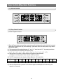
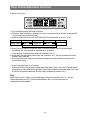
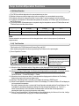
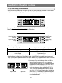
11-1) DISPLAY DESIGN
11-2) Temp Control Function
1) Freezer Temperature Control
※ When the Freezer button is pressed,the current set temp will be displayed.And, when the button is pressed
again within 5 seconds,it will carry out the following 1-2)and when there is no button press,it will go back to
the previous display.
1-1) The temperature will be selected between 8 ℉ and -14 ℉ at an interval of 2 ℉ by pressing one button.
1-2) The temperature will be selected in the following order.
(-2 ℉→-4 ℉→-6 ℉→-8 ℉→-10 ℉→-12 ℉→-14 ℉→8 ℉→6 ℉→4 ℉→2 ℉→0 ℉)
1-3) When power is on or there is a power failure,it will display the real temperature.
(It displays the real temperature when a function button is pressed)
1-4) The STD temperature for each step is as follows.(Based on 1/3H copper bar)
Step
1
2
3
4
5
6
7
8
9
Temp
8℉
6℉
4℉
2℉
0℉
-2℉
-4℉
-6℉
-8℉
10
11
-10℉ -12℉ -14℉
1-5) When the Freezer button is pressed,7-SEG will be changed immediately.But, its function will go into
operation in 10 seconds.
26
12
Temp Control &Operation Functions
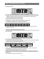
2) Fridge Temperature Control
2-1) The temperature will be selected between 46 ℉ and 34 ℉ at an interval of 2 ℉ by pressing one button.
2-2) When the Fridge button is pressed, the current set temp will be displayed.And, when the button is pressed
again within 5 seconds, it will carry out the following 2 -3) and when there is no button press for 10
seconds, it will display the finally selected temperature.
2-3) The temperature will be selected in the following order.
(38 ℉→36 ℉→34 ℉→46 ℉→44 ℉→42 ℉→40 ℉)
2-4) When power is on or there is a power failure,it will display the real temperature.
(It displays the real temperature when a function button is pressed)
2-5) The STD temperature for each step is as follows.(Based on 1/3H copper bar)
Step
1
2
3
4
5
6
7
Temp
45℉
44℉
42℉
40℉
38℉
36℉
34℉
2-6) When the Fridge button is pressed, 7-SEG will be changed immediately. But, its function will go into
operation in 10 seconds.
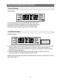
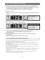
11-3) Super Freeze Function and Super Cool Functions
1) Super Freeze Function
1-1) It is selected by pressing the Super Freeze button.
1-2) When the Super Freeze button is pressed once,Super Freeze will be turned on.And then, it will repeat Off
and On each time you press the button after the above
1-3) With the initial Power On,the LED is off. (When the F-Room temperature is over 41℉ (5 ℃))
Category
Initial Power On
Pressed Once
Pressed Again
Display Change
OFF
Super Freeze
OFF
Other
A. When it goes into Super Freeze with the Super Freeze button pressed, the LED will be changed
immediately. But, its function will go into operation in 10 seconds.
(Comp and Fan will operate continuously for 2 and a half hours.)
B. When Super Freeze is selected,it goes into operation regardless of the compartment temperature.
C. During the operation of Super Freeze,the fridge compartment will be controlled according to the Fridge
Notch setting.
D. The Freezer display will show the real temperature.
27
Temp Control &Operation Functions
2) Super Cool Function
2-1) It is selected by pressing the Super Cool button.
2-2) When the Super Cool button is pressed once, Super Cool will be turned on. And then, it will repeat Off
and On each time you press the button.
2-3) With the initial Power On, the LED is off. (When the F-Room temperature is over 41℉ (5 ℃))
Category
Initial Power On
Pressed Once
Pressed Again
Display Change
OFF
Super Cool
OFF
Other
A. When it goes into Super Cool with the Super Cool button pressed, the LED will be changed
immediately. But, its function will go into operation in 10 seconds.
(Comp and Fan will operate continuously until it reaches to 28 ℉.)
B. Comp and R-Fan will operate continuously until it reaches to 28 ℉. But, the operation time will not
exceed 2 and a half hours.
C. During the operation of Super Cool, the freezer compartment will be controlled according to the
Freezer Notch setting.
※ Super Freeze and Super Cool Functions
Each function will go into operation independently. With Super Freeze, Comp and F-Fan will operate
continuously for 2 and a half hours regardless of the Fridge compartment and with Super Cool, Comp
and R-Fan will operate continuously until the Fridge compartment reaches to 28 ℉.
Note
When Super Freezer or Super Cool is selected with the Freezer temperature over 14 ℉ and the
Fridge temperature over 50 ¢™F,it will operate differently. But, it is not a normal case.So,
the explanation will be skipped.
28
Temp Control &Operation Functions
11-4) Ice Off Function
1) Ice Off Function
1-1) Year 2005 W2 Model is one with Auto Ice Maker and Ice Water Valve.
1-2) When the Ice Off button is pressed,the Auto Ice Maker does not operate.
1-3) Ice stored in the ice bin is available with the Ice Off button selected.
1-4) The Auto Ice Maker function is introduced in the Ice Maker function.
11-5) Child Lock Function
1) Child Lock Function
It operates with the
Child Lock button
pressed for 3 seconds.
1-1) When the Child Lock is selected,the Child Lock LED will light up.Press the button one more time to cancel
its function. When t he Chi l d Lock i s sel ect ed,al l of t he f unct i on but t ons do not operate.So,
temperature control ,Super and Ice Off functions wi l l keep their current settings.It is devised to prevent
children from changing the settings.
1-2) When the Child Lock button is pressed,the Child Lock LED will light up and when its function is
cancelled,the Child Lock LED will go off and other buttons will work.
- Select the function if necessary. But, keep it in mind that this function can bring up consumer calls. So, have a
better understanding of it.
29
Temp Control &Operation Functions
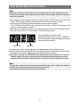
11-6) Buzzer Alarm Function
1) Button Touch Tone ("DING-DONG")
1-1) When each button on the control panel is pressed,it will send out an input signaling "DINGDONG"sound.
1-2) When buttons are not pressed correctly,it won't send out the "DING-DONG"sound.
1-3) Buttons are recognized within 0.2 sec and when buttons are pressed continuously, it sends out only
a "DING"sound.
1-4) This Button Touch sound has priority over other alarm sounds.
2) Door-Open Alarm Sound
2-1) With either of the doors open for more than 2 minutes continuously, it sends out a “ Ding Dong”
sound.
2-2) When the door keeps being opened, it will send out the "DING-DONG"sound every minute.
2-3) The alarm sound will stop immediately when both of the doors are closed.
3) Alarm Sound for Forced Operation &Forced Defrost ("BEEP" Sound)
3-1) When Forced Operation or Forced Defrost is selected, it will send out a "BEEP"sound.
3-2) When the Forced Operation button is pressed once,the "BEEP"sound (0.25Sec ON/0.75Sec OFF)
will keep on until it is cancelled automatically (24 Hr)or forcefully.
3-3) During Forced Operation, it will send out a "BEEP"sound until the Defrost is completed (idling time
included)or the cancellation is selected.)
3-4) With Forced R-Defrost,it will send out a "BEEP"sound (0.1sec ON/0.75sec OFF)and with Forced
F/R-Defrost,it will send out a "BEEP"sound (0.5sec ON/0.5sec OFF).
11-7) Machine Compartment F-Fan Motor Delay Function
1) The refrigerator is automatically controlled by temperature control programs according to the ambient
temperature. The machine compartment fan is controlled as follows according t o t he a mbi ent
temperature. The fan does operate or does not operate according to operating conditions with Comp
on. So, make sure to take it into consideration during service.
Machine
Compartment
Fan Delay
Function
Temp Range
Load Operation Status
Ambient Temp 71.6℉(22℃)or over
Machine Compartment Fan On with Comp On
Ambient Temp 62.6℉(17℃)~69.8℉(21℃) Machine Compartment Fan On in 3 minutes after Comp On
Ambient Temp 53.6 ℉(12 ℃)~60.8℉(16℃) Machine Compartment Fan On in 6 minutes after Comp On
Ambient Temp 44.6℉(7℃)~51.8℉(11℃) Machine Compartment Fan On in 9 minutes after Comp On
Machine Compartment Fan Off regardless of Comp
Ambient Temp 42.8℉(6℃)or under
30
Temp Control &Operation Functions
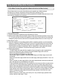
11-8) Ice Maker Function (Only applicable to Model with the Auto Ice Maker function)
- This Ice Maker function is an option.So,the following can be applied only to Model mentioned.
- Ice Maker has an automatic ice production function without extra controlling by users.
It is a kit performing a series of automatic ice producing operation that it supplies water and stores ice in the
ice bin upon the completion of ice production.
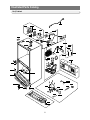
ICE-WAKER, KIT
EJECT-MOTOR
SUPT-RUBBER
EJECT-SENSOR
LEVELING-SWITCH
TEST-SWITCH
ICE
Full-SWITCH
SCREW
TRAY-ICE
FIXER-SENSOR
COVER-SENSOR
KNOB-TOUCH GUIDE-ICE(Lever to check ice full)
1) Initial Operation Function
1-1) When the initial power is applied,the ice tray will stand by for 2 hours.
1-2) After the 2-hour standby time,the Ice Maker Sensor will check the temperature and when it is lower than
5℉(-15℃)for more than 5 minutes,it will separate the ice from the ice tray into the ice bin by rotating and
twisting the ice tray.At this time,it carries out the ice separation whether there is ice in the ice tray or not.
2) Water Supply Function
2-1) Upon the completion of ice separating operation (initial ice separating operation, normal ice separating
operation,ice separating operation by Test funct i on) and t he horizontal leveling of the ice tray, when it is
evaluated that the ice tray is horizontally leveled, water will be supplied to the ice tray by turning on the
Water Solenoid in the machine compartment. (When it is detected as no water supply with low water
pressure taken into consideration, it will perform water supply operation up to 4 times.)
2-2) Water Supply Operation
- The Water Supply Valve opens after the completion of normal ice ejection, water is supplied for the
previously set option time (Factory set value:5.0 sec)and the Water Supply Valve is shut off.
- Water is to be supplied regardless of F/R-Door Open.
- The Ice Test S/W does not operate during water supply.
- After the water supply is completed, it will evaluate Water Supply or No Water Supply one and a half
minutes later.
- When it becomes water supply condition due to no water supply, water supply time will be 1.5 sec,1 sec
and 2 sec.
- When it is judged to do water supply after the 4-time water supply attempts, water supply operation will
stop. In this case,the ice eject will standby for 58 minutes.
- To prevent additional water supply due to the remaining ice in the ice tray slot with the ice maker sensor
on the bottom of it,it will stop water supply operation when there are no water supply signals keep on
after the water supply attempts for the number of previous water supply.For the first time water supply
after the power on,it will perform water supply once and if it is sensed as no water supply,it will stop water
supply operation.If the number of previous water supply is 3 times,it will try to supply water for 3 times.
And, if it is sensed as no water supply,it will stop water supply operation, In this case, the ice eject
standby time is 70~110 minutes.
- When it is sensed as no water suppl y conti nuousl y,it wi l l carry out water suppl y operation for the
number of previous water supply +1 times.
31
Temp Control &Operation Functions
2-3) Water Supply/No Water Supply Evaluation by Ice Maker Sensor
- When it passes one and a half minutes after the completion of water supply, it will evaluate Water
Supply/No Water Supply by comparing the temp changes of the Ice Maker Sensor on the bottom of the
Ice Tray. If the temperature of the Ice Maker Sensor is 35.6 ℉(2 ℃) (5 COUNT)higher when it is
measured in one and a half minutes after the completion of water supply operation than when it is
measured upon the completion of water supply,it will be evaluated as Water Supply.And, if it is increased
by lower than 35.6 ℉(2℃)or decreased,it will be evaluated as No Water Supply.
2-4) Water Supply Operation Spec with Ice Test S/W Input
- It will carry out water supply for once regardless of the previous water supply status.
- The ice eject standby time after the completion of water supply is the same as that after the completion of
the previous water supply regardless of the recognition of Water Supply/No Water Supply.
- The number of the previous water supply does not change.In other words, if the number of water supply
before the Ice Test S/W is pressed is 3 times, the number of previous water supply after the completion of
water supply by the Ice Test S/W is 3 times.
※ Example of Water Supply according to Water Pressure
On the Assumption of Room Temp over 18 ℃
Low Water Pressure
5s
5s
Initial 2HR Standby
1.5s
95+(5)MIN
5s
1.5s 1s
70+(5)MIN
No Water Supply
70+(5)MIN
No Water Supply
No Water Supply
Power On
High Water Pressure
5s
5s
58+(5)MIN
5s
95+(5)MIN
Water Supply
No Water Supply
58+(5)MIN
Water Supply
When ice is not
When ice is
separated from the separated from the
ice tray slot with the ice tray slot with the
sensor on it
sensor on it
High Water Pressure→ Low Water Pressure
5s
5s
58+(5)
MIN
Water
Supply
5s
95+(5)MIN
No Water Supply
1.5s
5s
1.5s 1s
70+(5)MIN
58+(5)MIN
No Water Supply
Water Supply
High Water Pressure Low Water Pressure
32
Temp Control &Operation Functions
Low Water Pressure → High Water Pressure
5s
1.5s 1s
2s
5s
5s
58+(5)MIN
58+(5)MIN
58+(5)MIN
Water Supply
Water Supply
Water Supply
High Water Pressure Low Water Pressure
3) Ice Making Function
- It is until the water in the Ice Tray is judged as completely frozen after the completion of water supply
operation. And, it is judged by the sensor temperature (can be set to other values).
3-1) When it passes 58 minutes after water is supplied to the Ice Tray,the Ice Maker Sensor temperature will
be.
3-2) When the Ice Maker Sensor maintains lower than 5℉ (-15℃)for 5 minutes,it will be evaluated as the
completion of ice making.
3-3) Standby for One Cycle:After the completion of the initialization with the power on, it will standby for a cycle
(2 hours)and carry out the ice ejecting operation even if the temperature conditions of the Ice Maker
Sensor are satisfied.
4) Ice Ejection Function
- After the completion of the ice making operation, the operation of ice separation from the ice tray will be
carried out as follows.Ice ejection will be performed by checking the status and the time of the Horizontal S/W
(if available)and the Lever S/W. When it is sensed as No Water Supply,it will carry out ice ejection for twice in
case ice is not seperated from the ice tray.
※ Motor Rotating Directions
- CW Rotation:The motor rotates in clockwise direction.
- CCW Rotation:The motor rotates in counter clockwise direction.
4-1) 1) Detailed movements by step during Ejection.
-1st step : Ejection Temp Check
Check whether the temp sensor is below -15 ℃ and whether the Ejection Standby time after Water
Supply has passed. At this time,the Ejection Standby time will be reset when it goes into F-Defrost
during the standby and it will be recounted from the beginning after the completion of Defrost.Then, it
checks if 58(58~110)minutes has passed.If the Ice Maker Sensor temp gets 5 ℉(-15℃)or lower and
maintains it for 5 minutes,it will carry on the next step.
- 2nd step : Full Ice Bin Check
To check if the ice bin is full,it will check whether the Ice Full S/W is ON/OFF (Low/High).
If the Ice Full S/W is ON (Low),it means the ice bin is full and it will standby without ejection.And as the
Ice Full S/W signal is changed to OFF and it will carry out the ejection in 40 minutes.
- 3rd step : Ice Tray Rotation (clockwise)
The Eject Motor rotates clockwise for a certain time and turns over the ice tray.At this point, the Feeler
Arm will be raised up to prevent ice from contacting it The ice tray will rotate for up to one minute or until
the Leveling S/W is ON(Low)after 5 sec.from the beginning of the third step when referring to the
Leveling S/W.If F-Door is open,it will stop rotating and resume the operation when the door is
closed.During the pause, clockwise rotation will is not counted.
- 4th step : Ice Ejection (Standby for 2 sec.at the maximum twist point)
It is operation twisting the ice tray one more time with its reversed state to separate ice from the ice tray
completely.The ice tray will standby for 2 seconds at the maximum twist point.
33
Temp Control &Operation Functions
- 5th step:Restoration to Horizontal State (counter clockwise)
The ice tray restores to its horizontal position by rotating the Ice Eject Motor counter clockwise When the
Leveling S/W is ON (Low)after 5 seconds, it will stop rotating. At this point, the raised Feeler Arm will get
lowered again and set on the highest point of stored ice to check the ice level.
- 6th step:Initialization of motor (clockwise)
Upon the completion of ice ejection, it will carry out 2)Water Supply to fill the ice tray.
5) Test Function
- It is to operate forcefully for the purpose of operation tests,A/S,maintenance,etc. And, it operates when the Ice
Test S/W (refer to Ice Maker Kit)is pressed for more than one and a half seconds.
5-1) This test button is not selected during water supply or ice ejection. It will carry out the test function when
being selected with water supply or ice ejection being completed. When the test button is selected, the Ice
Eject Motor will rotate ejecting ice regardless of the ice making temperature.And then, it will be restored to
the horizontal level and supply water to the ice tray.
5-2) It operates normally regardless of the F,R-Door opening
5-3) The other functions are the same as the ice ejection and the water supply operation.
5-4) Even when it stops ice-maki ng due to errors more than 3 times during normal operation,the Test S/W
shall work.At this time,when it performs normal ice ejection and water supply by pressing the Test S/W,it
will send out a “Ding Dong” sound before supplying water and carry out normal ice production by
canceling the 3-time error mode.
6) Ice Making Stop (Ice Off Function)
- When there is no demand for ice,turn off the Ice Off button on the display and stop ice making.
6-1) Whenever the Ice Off button is pressed on the display,the Ice Off LED will repeat On (light up)and Off (go off).
6-2) When power comes on,it will check the previously setting and display it.(The F-Room temperature should
be lower than 50 ℉.)
6-3) If necessary,turn off the ice maker by pressing the Ice Off button.Then, the ice maker will not produce ice.
6-4) When the function is selected,the indicator will be off immediately. But, when the ice maker is supplying
water,ejecting ice or performing horizontal leveling,it will stop operating after the completion of the next
water supply.
6-5) When the ice making function is selected again,it will accumulate time from the point of the selection and
carry out the normal ice making and ejection functions after checking the Ice Maker Sensor temperature in
90 minutes.
7) Function according to F-Door Open
- When F-Door is open,it will stop the operation to minimize the noise.
7-1) When F-Door is open during the ice ejection or horizontal leveling,it will stop operating and resume its
operation right after the door is closed again.
7-2) During water supply,it will carry on the water supply regardless of the state of the doors.
7-3) Therefore,when the freezer door is opened,the Ice Tray will stop operating.So you can find that the Ice
Tray is slanted or rotated partially with the door open.So,shut off the freezer door and wait for more than
30 seconds.Then,check if the Ice Tray is leveled horizontally.If not,it can be regarded as product
failure.When the ice ejection stops upon the opening of the freezer door,the Test function does not work
because it is normal operation and it will operate upon the completion of the water supply.
34
Temp Control &Operation Functions
11-9) Defrost Function
1) The F/R-Room defrost depends on the accumulated comp-on time.
2) With the initial power on,defrost starts at the both rooms after 4 hour accumulated comp-on time.
3) The defrost cycle can be changed from Min 6 hours to Max 7 hours according to various conditions.
4) The defrost cycle depends on the ambient temperature,the frequency of F/R-Door open and the duration of
the F/R-Door open.
5) The Defrost Heater Off temperatures are compared using the temperature values of R-Defrost Sensor and
F-Defrost Sensor and they are as follows.
Defrost Start
Defrost Restoration Temp
R-Room
Lower than 50℉(10℃)
62.6℉(17℃)
F-Room
Lower than 23℉(-5℃)
53.6℉(12℃)
Etc
Note
Defrost restoration temperatures could be changed without notice for the purpose of performance
improvements.
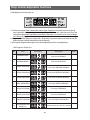
11-10) Test Function
�This function is for PCB,Product and Process Test, and SVC.
�After checking the product functions by selecting Test S/W,turn on the power again.
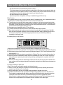
1) Forced Operation Function
Display for Forced Operation
Display for Forced Operation and How to Turn it On
① (Press for 8 seconds simultaneously) +
② All LEDs Off, Press one of the following
buttons (Super Freeze, Super
Cool,Freezer, Fridge Key)
1-1) When the Super Cool button and the Fridge button on the display panel are pressed for 8 seconds
simultaneously,the display panel will be shifted to the Test Setting Mode and all the LEDs will be off.
1-2) When any of Super Freeze,Super Cool,Freezer and Fridge buttons is pressed within 15 seconds with the
display panel shifted to the Test Setting Mode, it will be selected in the order of Forced Operation →
Forced R-Defrost → Forced F/R-Defrost → Cancel.
1-3) When there is no button press within 15 seconds after the display panel is shifted to the Test Setting
Mode,it will go back to the previous display mode.
1-4) When the Test Setting Mode is selected or cancelled,it will send out a "BEEP"sound.
1-5) When Forced Operation is selected,the F-Room LED will display "FF"and the R-Room LED will display its
real compartment temperature.
But, when it passes more than a minute with Forced Operation selected,and then Forced Defrost or Test
Cancellation is selected,the temperature setting will not be changed (maintaining -14 ℉and 34℉)
When Forced Defrost or Test Cancellation is selected within a minute after Forced Operation is
selected,the Notch will go back to the previous notch setting.
1-6) During Forced Operation,the Full-Down function will be maintained only for 24 hour s.Af t er t hat, it will go
in to normal operation after carrying out F/R-Defrost automatically.
35
Temp Control &Operation Functions
1-7) To cancel For ced Oper at i on,t ur n of f and on t he power or select the Test Cancellation Mode.
1-8) It will send out an alarm sound (0.25sec ON/0.75sec OFF)during Forced Operation until it is completed.
It will keep on alarming regardless of the selection or cancellation of the alarm button.
1-9) When Forced Operation is selected, Super Freeze and Super Cool won't operate.
2) Forced Defrost Function
2-1) When the Test button is pressed one more time during Forced Operation, it will go into R-Room Forced
Defrost.
Display for Forced R-Defrost
-. Press one of Super Freeze, Super Cool,
Freezer, Fridge buttons once during
Forced Operation
2-2) When it is selected once more, it will go into F/R-Defrost.
Display for Forced F/R-Defrost
Display for Forced F/R-Defrost
-.Press one of Super Freeze, Super
Cool,Freezer,Fridge buttons once during
Forced R-Defrost Operation
2-3) When it goes into Forced Defrost,Forced Operation will be cancelled automatically.
And then, it will carry out normal operation after completing Forced Defrost.
3) Test Cancellation Mode
3-1) When the Test button is pressed once more during F/R-Forced Defrost, it will go back to
normal operation.
3-2) When the Test Cancellation Mode is selected, it will stop alarming.
11-11) Function when the power is applied for the first time.
1) When power is applied,it will carry out the initial self diagnosis. And, if there is no error, all the
LEDs on the display panel will light up for 2 seconds.
2) When there is any error found during the initial self diagnosis,relevant LEDs will blink at an
interval of 0.5 sec.
3) After lighting up all the LEDs for 2 seconds,the display panel will display the real temperatures
of the F-Room and the R-Room.
4) It will turn on R-Defrost Heater and F-Defrost Heater at an interval of 0.5 sec and keep them
being turned on for 3 seconds.
5) When the initial F/R-Defrost is completed,COMP, C-FAN,F-FAN and R-FAN will be on at an
interval of 0.5 sec and t hey wi l l operat e for 5 mi nut es regardless of the compartment
temperatures.
6) When the Test S/W is pressed during 4)and 5),the functions related to 4)and 5)will stop
immediately and it will go into the Test function.
36
Temp Control &Operation Functions
11-12) Power Compensation Function
1) Notch Save Function
1-1) Whenever the Super Freeze, Super Cool, Fridge or Freezer button is pressed, it will save the current
display setting. And, when the power goes off and comes back on, it will display the stored setting.
(But, the Test Mode will not be saved.)
1-2) Upon the initial power on,the above 1-1)will be performed when the F-Room temperature is lower than
41℉(5℃)and it will operate on the initial mode regardless of the saved setting when the temperature is
over 41℉(5℃).
1-3) When the power goes off during Super Freeze and comes back on, it will carry out Super Freeze when
the F-Room temperature is lower than 41℉(5℃). But, the previously accumulated operating time will be
reset and it will count from the start.
1-4) When the power goes off during Super Cool and comes back on, it will carry out Super Cool when the FRoom temperature is lower than 41℉(5℃). But, the previously accumulated operating time will be reset
and it will count from the start.
1-5) When the power is off with various functions in operation, it will light up the entire display for about 3
seconds from the power-on point regardless of the notch save if the F-Room temperature is lower than
41℉(5℃).
※ Exhibition Mode
- When the Super Freeze and the Freezer buttons are pressed for 5 s econds simultaneously, it will go into the
Exhibition Mode with a “Ding-Dong” sound.
- With the Exhibition Mode selected, the compressor will be off immediately and there will be no defrost.
- Press the Super Freeze and the Freezer buttons for 5 seconds simultaneously to cancel the Exhibition Mode.
Then, it will carry out the normal operation.
11-13) Self Diagnosis Function
1) Self-diagnosis with initial power on
1-1) With power on, MICOM checks the temperature sensors for errors in a second.
1-2) If inferior sensor is found by self-diagnosis, relevant display LEDs will be all on and off at the interval of 0.5
sec. (There will be no beep sound with at this time.)
1-3) When display LEDs are blinking with inferior sensors found, it only recognizes the self-diagnosis buttons
and normal temp control will be on hold.
1-4) Upon self-diagnosis error, when the faulty sensor is repaired or when the Super Freeze button and the
Super Cool button are pressed for 5 sec simultaneously, the initial self diagnosis will be canceled
automatically. (Below, How to Select)
37
Temp Control &Operation Functions
2) Self-diagnosis with initial power on
2-1) When pressing the Super Freeze button and the Super Cool button simultaneously for 6 sec during
normal operation, the entire temperature setting display will blink for 2 sec at the interval of 0.5 sec and
when pressing the Super Cool button and the Super Cool button si mul taneousl y for 8 sec including 2
sec blinking, self-diagnosis will be selected.
2-2) It goes into the Self Diagnosis function with a “Ding-Dong” sound and it shows error codes on the LED
display.And then,it will be restored to the normal operation.
2-3) During self-diagnosis,button inputs will not be recognized but only the canceling buttons.
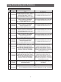
- Self Diagnosis Check List
No
Error
LED Display
Description
1
F-SENSOR ERROR
Fault rated F-SENSOR?
2
R-SENSOR ERROR
Fault rated R-SENSOR?
3
F-DEFROST SENSOR ERROR
Fault rated F-DEFROST SENSOR?
4
R-DEFROST SENSOR ERROR
Fault rated R-DEFROST SENSOR?
5
ICE MAKER SENSOR ERROR
Fault rated ICE MAKER SENSOR?
6
AMBIENT SENSOR ERROR
Fault rated AMBIENT SENSOR?
7
F-DEFROST HEATER ERROR
Fault rated F-DEFROST?
8
R-DEFROST HEATER ERROR
Fault rated R-DEFROST?
9
ICE MAKER FUNCTION ERROR
Fault ICE MAKER OPERATION?
10 UART COMMUNICATION
ERROR (PLC)
Communication error with PLC modem
38
Others
Temp Control &Operation Functions
- Descriptions for each Self Diagnosis Lamp
No
Item
Error
Self Diagnosis
SENSOR HOUSING SLIP-OUT, CONTACT
VOLTAGE BETWEEN MAIN PCB CN30
DEFECT,WIRE CUT, WIRE SHORT,
SENSOR TEMP MORE THAN 122℉
2↔3 SHALL BE WITHIN 4.5V~1.0V.
(+50℃) OR LOWER THAN 122℉(-50℃)
1
F-SENSOR
2
SENSOR HOUSING SLIP-OUT, CONTACT
VOLTAGE BETWEEN MAIN PCB CN30
DEFECT, WIRE CUT, WIRE SHORT,
R-SENSOR
SENSOR TEMP MORE THAN
6↔7 SHALL BE WITHIN 4.5V~1.0V.
122℉(+50℃)OR LOWER THAN 122℉(-50℃)
3
F-DEFROST
SENSOR
SENSOR HOUSING SLIP-OUT, CONTACT
VOLTAGE BETWEEN MAIN PCB CN30
DEFECT, WIRE CUT, WIRE SHORT,
SENSOR TEMP MORE THAN
2↔4 SHALL BE WITHIN 4.5V~1.0V.
122℉(+50℃)OR LOWER THAN 122℉(-50℃)
4
R-DEFROST
SENSOR
SENSOR HOUSING SLIP-OUT, CONTACT
VOLTAGE BETWEEN MAIN PCB CN30
DEFECT, WIRE CUT, WIRE SHORT,
SENSOR TEMP MORE THAN 122℉
6↔8 SHALL BE WITHIN 4.5V~1.0V.
(+50℃)OR LOWER THAN 122℉(-50℃)
5
SENSOR HOUSING SLIP-OUT, CONTACT
VOLTAGE BETWEEN MAIN PCB CN90
DEFECT, WIRE CUT, WIRE SHORT,
I/M-SENSOR
SENSOR TEMP MORE THAN
3↔4 SHALL BE WITHIN 4.5V~1.0V.
122℉(+50℃)OR LOWER THAN 122℉(-50℃)
6
7
8
9
AMBIENT
SENSOR
SENSOR HOUSING SLIP-OUT, CONTACT
VOLTAGE BETWEEN MAIN PCB CN31
DEFECT, WIRE CUT, WIRE SHORT,
SENSOR TEMP MORE THAN
1↔4 SHALL BE WITHIN 4.5V~1.0V.
122℉(+50℃)OR LOWER THAN 122℉(-50℃)
F-ROOM HEATER (SENSOR HOUSING SLIP- AFTER SEPARATING THE MAIN PCB CN70 WIRE FROM
OUT, CONTACT DEFECT, WIRE CUT, WIRE PCB, CHECK THE RESISTANCE BETWEEN BROWN ↔
SHORT OR TEMP FUSE DEFECT)
ORANGE. IT SHALL BE WITHIN ***OHM. (THE
F-DEFROST
WHEN DEFROST DOES NOT FINISH EVEN
RESISTANCE VARIES ACCORDING TO THE INPUT
ERROR
AFTER A 70-MINUTE CONTINUOUS
POWER.) WHEN THE RESISTANCE IS 0 OHM,CHECK IF
HEATING, IT DISPLAYS THE ERROR.
THE HEATER IS SHORT AND WHEN IT IS ∞OHM, CHECK
IF THE WIRE/TEMP FUSE IS OPEN
R-ROOM HEATER (SENSOR HOUSING
AFTER SEPARATING THE MAIN PCB CN70 WIRE FROM
SLIP-OUT, CONTACT DEFECT, WIRE CUT,
PCB,CHECK THE RESISTANCE BETWEEN WHITE ↔
ORANGE.IT SHALL BE WITHIN ***OHM. (THE
R-DEFROST WIRE SHORT OR TEMP FUSE DEFECT)
WHEN
DEFROST
DOES
NOT
FINISH
EVEN
RESISTANCE
VARIES ACCORDING TO THE INPUT
ERROR
AFTER A 80-MINUTE CONTINUOUS
POWER.) WHEN THE RESISTANCE IS 0 OHM,CHECK IF
HEATING, IT DISPLAYS THE ERROR.
THE HEATER IS SHORT AND WHEN IT IS ∞OHM,CHECK
IF THE WIRE/TEMP FUSE IS OPEN
MORE THAN 3 TIMES OF ICE MAKER
I/M
FUNCTION KIT ICE EJECTION OR HORIZONTAL
LEVELING ERROR
ERROR
ONLY APPLIED TO MODEL WITH
ICE MAKER
Communication error with PLC modem
When it is not connected with PLC modem
Uart
Communication
Note) PLC Communication modem will be applied optionally.
10
Error (PLC)
So even if the appliance which does not apply PLC displays this error digit, It is not defect.
39
Temp Control &Operation Functions
11-14) Power Compensation Function
It is the initial Sensor Error Display. Hold
on the Super Freeze and the Super Cool
buttons for 3 seconds and take off the
fingers. Then, press the Fridge button.
1) During the normal operation,when the Super Freeze and the Super Cool buttons are pressed for 3 seconds
at the same time, the Freezer and the Fridge temp LEDs will blink for 2 seconds at the interval of 0.5 second.
2) At this time, when pressing the Fridge button (“Ding-Dong “ goes off)after taking off the fingers from the
Super Freeze and the Super Cool buttons, it will be changed to the Load Status Display Mode.
3) The Load Status Display Mode only shows the status of the load operation command from MICOM.
MICOM sends out command signals. So, it does not mean the related components are in operation. For
example, even though it shows that a load is operating,it is not operating due to the load defect or the PCB
relay defect.It can be applied to A/S.
4) The Load Status Display function maintains for 30 seconds and it goes back to the normal operation.
- Self Diagnosis Check List
LOAD
DISPLAY
R-FAN
R-Room second digit "a"
R-DEFROST HEATER
R-Room second digit "c"
COMPRESSOR
F-Room second digit "a"
F-FAN
F-Room second digit "b"
F-DEFROST HEATER
F-Room second digit "b"
INITIAL START MODE
R-Room second digit "b"
OVERLOAD MODE
R-Room second digit "e"
LOW TEMP MODE
R-Room second digit "f"
R-LAMP
F-Room first digit "b"
F-LAMP
F-Room first digit "a"
EXIHIBITION MODE
R-Room second digit "g"
40
OTHERS
Temp Control &Operation Functions
11-15) Option Setting Function (EEPROM)
- During the normal operation,when the Super Cool and the Freezer buttons are pressed for 12 seconds,the
Fridge or Freezer temp setting display will be shifted to the Option Setting Mode.
How to Control Option Mode Shift Button by Model
When the Super Cool and the Freezer buttons are pressed for 12 seconds at the same time, the
Fridge/Freezer display will be shifted to the Option Setting Mode.
How to Control Button after shifting into Option Mode
Option Value Setting
Down Key
Option Setting
Down Key
Option Value Setting
Up Key
Option Setting
Up Key
※ Button Press at Option Mode
Press Super Freeze
Option Value Down (Decrease)
Press Freezer
Option Value Up (Increase)
Press Super Cool
Option Moving Down
Press Fridge
Option Moving Up
- When the display is shifted to the Option Setting Mode, all the LEDs will be turned off except Freezer and
Fridge. (All the options operate according to the Option Table. So, only Fridge and Freezer will be introduced.)
Option Value
Option Item
1) For example,if you want to change option and shift the
standard temp of R-Room to 28.4℉(-2℃),follow the
directions below. This function is to change the standard
temp and if the current standard temp of F-Room is -2℉(19℃), it can be lowered by 28.4℉(-2℃)using the options
and the standard temp will be controlled at -6℉(-21℃).
That is, in the case of changing temp options, although
you set it to -2℉(-19℃)on the display panel, the fridge will
operate to -6℉(-21℃)internally. Therefore, the temp will
be controlled by lowering 28.4 ¢µ(-2℃)compared to that
set on the display panel.
41
Temp Control &Operation Functions
Note
Basically,when sending out products,their option will be all cleared. That is,their set values are all “0”.
However, for the purpose of quality improvement, set values could be changed. Therefore, make sure to
check quality information
2) After changing to the Option Mode,the display panel will blink "0"(ALL OFF)for R-Room and "0"(ALL OFF)for
F-Room. (When sending out products, there shall be "0"set for R-Room and "0"set for F-Room.
But,for the purpose of quality improvement,the standard set values can be changed.)
- If only "0"for R-Room blinks,F-Room temp option item will be set and the current F-Room temp set value will
be shown on the temp display of F-Room.
3) After setting "0"for R-Room and selecting "6"as in the option table of F-Room below, the standard temp of FRoom will be lowered by 28.4℉(-2.0℃). (Refer to F-Room temp change figure)
: In 20 seconds after the completion of the
adjustment,MICOM will store the set value in EEPROM
and it will be restored to the normal display and the option
setting mode will be cancelled.
Option Value
Option Item
4) The above option setting method is the same for all models whether they have Ice Maker or not.
5) With the same as the above method,R-Room Temp,Water Supply Qty, Ice Maker Eject Temp/Time,Defrost
Restoration Temp, Hysteresis & Notch Gap for each temperature can be controlled.
6) Since option is already set in EEPROM while sending out products at the factory, do not change it
randomly except for special occasions and do not turn off power before restoring to the normal
display because option will be completed when it is restored to the normal display in 20 seconds.
Note
There are other options including the functions mentioned above. But, they are related to the refrigerator
controlling.They are dropped here since they are not relevant to A/S.
(Do not set other options except for those in this A/S manual.)
42
Temp Control &Operation Functions
11-16) Option Table
1) F-Room Temp Shift Table
Set Item
F-Room Temp Shift
Model
Common (All Models)
Option Item
Set Value
Freezer LED
Fridge LED
0
Option Value
0
0
1
31.1℉(-0.5℃)
2
30.2℉(-1.0℃)
3
29.3℉(-1.5℃)
4
28.4℉(-2.0℃)
5
27.5℉(-2.5℃)
6
26.6℉(-3.0℃)
7
25.7℉(-3.5℃)
8
32.9℉(+0.5℃)
9
33.8℉(+1.0℃)
10
34.7℉(+1.5℃)
11
35.6℉(+2.0℃)
12
36.5℉(+2.5℃)
13
37.4℉(+3.0℃)
14
38.3℉(+3.5℃)
15
39.2℉(+4.0℃)
Option Value
Option Item
Ex) When raising the Freezer standard temperature
by 28.4℉(-2℃)
43
Temp Control &Operation Functions
2) R-Room Temp Shift Table
Set Item
R-Room Temp Shift
Model
Common (All Models)
Option Item
Set Value
Fridge LED
Fridge LED
1
Option Value
0
0
1
31.1℉(-0.5℃)
2
30.2℉(-1.0℃)
3
29.3℉(-1.5℃)
4
28.4℉(-2.0℃)
5
27.5℉(-2.5℃)
6
26.6℉(-3.0℃)
7
25.7℉(-3.5℃)
8
32.9℉(+0.5℃)
9
33.8℉(+1.0℃)
10
34.7℉(+1.5℃)
11
35.6℉(+2.0℃)
12
36.5℉(+2.5℃)
13
37.4℉(+3.0℃)
14
38.3℉(+3.5℃)
15
39.2℉(+4.0℃)
Option Value
Option Item
Ex) When raising the fridge standard temperature
by 35.6℉(+2℃)
44
Temp Control &Operation Functions
- The following options are only applicable to the models with Ice Maker.
The following can not be set to the models without Ice Maker
3) Ice Maker Sensor Temp Shift
This is the standard temperature checking if ice in
the ice tray is frozen completely.
4) Ice Maker Water Supply Time Control Function
It is an option for Water Supply Time and it may be
deleted when the time is confirmed at the factory.
Set Item
LED
(Fridge)
Set Item
LED
(Fridge)
Ice Maker Sensor
Standard Temp Control
4
Ice Maker Water
Supply Time Control
20
Set Value
F-Room Temp Set Value
Set Value
Option Value
F-Room Temp Set Value
Option Value
0
5.0℉(-15℃)
0
5 sec
1
3.2℉(-16℃)
1
6 sec
2
1.4℉-17℃)
2
7 sec
3
7.8℉(-14℃)
3
8 sec
4
8.6℉(-13℃)
4
9 sec
5
10.4℉(-12℃)
5
10 sec
6
12.2℉(-11℃)
6
11 sec
7
14.0℉(-10℃)
7
12 sec
Ex) When changing the Defrost Sensor
temperature to 1.4℉(-17℃)
Option Value
Ex) When changing the water supply time to 9
seconds
Option Item
Option Value
45
Option Item
12. OPERATION PRINCIPLES BY PARTS OF CIRCUIT
12-1) SOURCE POWER CIRCUIT
∙∙∙∙∙∙∙∙∙∙∙∙∙∙∙∙∙∙∙∙∙∙∙∙∙47
12-2) OSCILLATION CIRCUIT ∙∙∙∙∙∙∙∙∙∙∙∙∙∙∙∙∙∙∙∙∙∙∙∙∙∙∙∙47
12-3) RESET CIRCUIT ∙∙∙∙∙∙∙∙∙∙∙∙∙∙∙∙∙∙∙∙∙∙∙∙∙∙∙∙∙∙∙48
12-4) EEPROM DETECTION CIRCUIT ∙∙∙∙∙∙∙∙∙∙∙∙∙∙∙∙∙∙∙∙∙∙∙48
12-5) DOOR SWITCH DETECTON CIRCUIT
12-6) TEMP SENSING CIRCUIT
∙∙∙∙∙∙∙∙∙∙∙∙∙∙∙∙∙∙∙48
∙∙∙∙∙∙∙∙∙∙∙∙∙∙∙∙∙∙∙∙∙∙∙∙∙∙49
12-7) ICE MAKER OPERATION CIRCUIT
12-8) DISPLAY DRIVING CIRCUIT
∙∙∙∙∙∙∙∙∙∙∙∙∙∙∙∙∙∙∙∙∙50
∙∙∙∙∙∙∙∙∙∙∙∙∙∙∙∙∙∙∙∙∙∙∙∙∙51
12-9) LOAD DRIVING CIRCUIT ∙∙∙∙∙∙∙∙∙∙∙∙∙∙∙∙∙∙∙∙∙∙∙∙∙∙∙52
12-10) BUZZER CIRCUIT DIAGRAM ∙∙∙∙∙∙∙∙∙∙∙∙∙∙∙∙∙∙∙∙∙∙∙∙53
12-11) MODEL OPTION CIRCUIT
∙∙∙∙∙∙∙∙∙∙∙∙∙∙∙∙∙∙∙∙∙∙∙∙∙53
46
OPERATION PRINCIPLES BY PARTS OF CIRCUIT
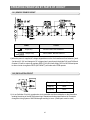
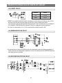
12-1) SOURCE POWER CIRCUIT
Circuit
Power
Vcc(DC 5V)
MICOM POWER AND SENSORS
+12V(DC 12V)
RELAY,PANEL DRIVING CIRCUIT
1) When the power is supplied,AC voltage stepped down on the 2nd transformer flows between ①and
③at about AC 16V and changes to DC voltage when it goes through the diode D101 and D108,and
constant 12V will be output via regulator REG1(7812).And,it will supply DC5V to MICOM and power
to other circuits via regulator REG2 (MC7805ACT),and make entire PCB operate.
12-2) OSCILLATION CIRCUIT
Terminal
Oscillation Freq.
Xin(#19)
8MHz
Xout(#18)
8MHz
1) It is an Oscillation Circuit for synchronism clock generation and time calculation on the information
sending &receiving of the MICOM internal logic elements and when specifications for Resonator
change,the timing system of MICOM changes resulting in errors. (Rated parts must be used)
47
OPERATION PRINCIPLES BY PARTS OF CIRCUIT
12-3) RESET CIRCUIT
Terminal
Power
Vcc
DC 5V
Reset
DC 5V
1) RESET Circuit allows the whole program to go back to the initial setting by initializing parts such as
the RAM in MICOM with the power supply into MICOM or with an instant power failure.
Upon the power supply,the reset terminal voltage becomes "LOW" for several tens of ㎲ compared to
Vcc voltage(DC 5V)at MICOM,and it maintains "HIGH"(Vcc Voltage)during normal operation.
But, when Vcc drops down to 3.4~3.7V, the reset terminal voltage becomes "LOW".
12-4) EEPROM DETECTION CIRCUIT
1) A semiconductor memory EEPROM stores data remembering previous settings regardless of
power-off,which are indispensable especially in power fluctuating areas.Also,EEPROM sets and
uses other options in principle.
12-5) DOOR SWITCH DETECTON CIRCUIT
48
OPERATION PRINCIPLES BY PARTS OF CIRCUIT
ITEM
DOOR OPEN/CLOSE
DOOR S/W CONTACT POINT
CLOSE
MICOM
PIN NO
“HIGH”
OPEN
F
# 42
OPEN
CLOSE
CLOSE
OPEN
“LOW”
“HIGH”
R
# 43
OPEN
MICOM INPUT
CLOSE
“LOW”
1) If F-Door is opened,the contact point of the door switch (4-1)becomes closed.Then,the power of
the PCB line flows to the door switch through R404 and 0V is applied to the MICOM
terminal.And, when the door is closed,the contact point of the door switch (4-1)becomes
open.Then,the power of the PCB line supplies 5V to MICOM via R404 and R401,which
recognize the door as closed,turn on the fan at the extra load terminal and control the Room
Lamp Relay (K73)turning off the lamp.
2) If R-Door is opened,the contact point of the door switch (2-1)becomes closed.Then,the power of
the PCB line flows to the door switch through R403 and 0V is applied to the MICOM
terminal.And, when the door is closed,the contact point of the door switch (2-1)becomes
open.Then,the power of the PCB line supplies 5V to MICOM via R403 and R402,which
recognize the door as closed,turn on the fan at the extra load terminal and control the Room
Lamp Relay (K75)turning off the lamp.
12-6) TEMP SENSING CIRCUIT
1) Sensor uses a thermistor which has a temp coefficient of negative resistance and controls
resistance.When the heat goes up,the resistance gets down and vice versa.R301~R305and
C301~C303 are parts for noise prevention but they are not related to temp sensing
characteristics.
2) If Vf is the incoming voltage to MICOM in case of F-Sensor,Vf equals (Rth *Vcc)/((R312 +Rth).
Where Rth is resistance of THERMISTOR corresponding to Temp.Please refer to the Appendix
Temp-to-Sensor Resistance/Voltage conversion table(Temp-to-MICOM Terminal Voltage
included)on A/S. (89page)
49
OPERATION PRINCIPLES BY PARTS OF CIRCUIT
12-7) ICE MAKER OPERATION CIRCUIT
1) The ice maker circuit above is to control the ice maker kit installed on the F room.
This circuit is the hardware to control ejection and horizontal positioning,ice making temperature
detection and full icing detection. Temperature detection circuit is the same as temperature
detection circuit on 4-6 and the explanation will be skipped and only the ejection circuit will be
explained. If MICOM PORT NO #7 is outputted with High to rotate motor in ejection direction
and the pin #5 of IC90 is inputted,12V is outputted on pin #2 of IC90,goes to motor and supplied
to pin #10 of IC90. The current flows to the pin #10 of IC90 making motor rotates.This motor
rotates the gear and rotates the ejection tray.The tray twists to separate the ice from the tray
and return to the horizontal state. For restoration,motor stops for 2 seconds when the ejection is
completed and to rotate in opposite direction,output horizontal MICOM PORT NO #46 with high
and perform horizontal positioning. Motor rotation for ejection operates for 8.3 seconds and
stays for 2 seconds.Horizontal positioning rotates motor in opposite direction and it stops when
the horizontal switch becomes ON (Low)or when the voltage of the motor voltage sensing part
(MICOM PORT #60)is over 0.55V. The test S/W is off in normal cases and MICOM PORT 50
stays high.When necessary,press the switch for more than 1.5 seconds executing forced
ejection.Full S/W has a lever that detects the amount of ice in the ice-maker kit and based on
the status of MICRO S/W connected to the lever, if ice is full in the container,ejection is not
executed,and only if it is off (MICOM PORT 48 is high), the ejection is executed.
50
OPERATION PRINCIPLES BY PARTS OF CIRCUIT
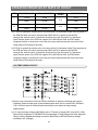
12-8) DISPLAY DRIVING CIRCUIT
1) KEY SCAN &DISPLAY DRIVING PRINCIPLE
As shown in the wave diagram below,Micom sends out “high ”signals through the MICOM 6
terminals of NO #1→2→3→4→5→6 for 2ms each every 12ms.This signal goes to output terminal
via input terminal of IC51 (TD62783AP or KID65783AP). Here, the peak to peak voltage of the
square wave is 11~12V DC and each output wave is as follows.
V
2msec
10msec
GRID #1
GRID #2
GRID #3
GRID #4
GRID #5
GRID #6
T
51
OPERATION PRINCIPLES BY PARTS OF CIRCUIT
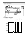
12-9) LOAD DRIVING CIRCUIT
1) The main PCB processes most of the load control for electronic refrigerators.
2) Compressor,F-Room,defrost heater,and other functions are controlled by relays.
3) For example,to operate the compressor,MICOM Pin #22 outputs high (5V)signals which go into IC70 Pin
#7.The IC70 Pin #7 plays the same role as the base of NPN TR.The Pin #12 works as the collector of TR.
So,if 5V is supplied to the Pin #7 of IC70,the Pin #12 will be turned on and connected to the
ground.Then,the relay K72 and the coil connected to the Pin #12 of IC70 becomes low (OV)and +12V
(opposite side of coil)flows to the Pin #12 of IC70 via the coil and goes into the ground.
While current flows to the coil,the magnetic power arise,it turns on the secondary contact point inside
K72,and operates when the AC power is supplied to the both sides of the compressor.
When MICOM Pin #22 becomes Low(0V),IC70 Pin #7 becomes Low which cut out the power and the
current of RY75 RELAY.So,the secondary contact becomes off due to the magnetic field cut,which
turns off the compressor.
All other loads work based on the same principle.The defrost heater operates only if the
compressor is turned off like the circuit above and it is connected like the equivalent circuit below.
- COMP & DEFROST HEATER EQUIVALENT
CIRCUIT AC~INPUT POWER
52
OPERATION PRINCIPLES BY PARTS OF CIRCUIT
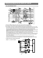
12-10) Buzzer Circuit Diagram
1) The circuit is composed of like the above and MICOM controls the alarm function with 2KHz.12V is
always applied to the circuit.So,when MICOM sends alarm signals to Q801 Transistor Bass,the
transistor is turned on applying 12V to the buzzer,which operates the buzzer. 4.7Kohm of R801 is a
resistance for the production of quality buzzer sound.
53
13. DIAGNOSTICS
13-1) When power is not supplied ∙∙∙∙∙∙∙∙∙∙∙∙∙∙∙∙∙∙∙∙∙∙∙∙∙∙55
13-2) If there is a trouble with self-diagnosis ∙∙∙∙∙∙∙∙∙∙∙∙∙∙∙∙∙∙∙∙56
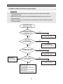
13-3) When COMP does not operate
13-4) When FAN does not operate
∙∙∙∙∙∙∙∙∙∙∙∙∙∙∙∙∙∙∙∙∙∙∙∙59
∙∙∙∙∙∙∙∙∙∙∙∙∙∙∙∙∙∙∙∙∙∙∙∙∙60
13-5) When Defrost does not operate ∙∙∙∙∙∙∙∙∙∙∙∙∙∙∙∙∙∙∙∙∙∙∙∙63
13-6) When Alarm Sound continues without stop
∙∙∙∙∙∙∙∙∙∙∙∙∙∙∙∙∙65
13-7) Panel PCB Defect∙∙∙∙∙∙∙∙∙∙∙∙∙∙∙∙∙∙∙∙∙∙∙∙∙∙∙∙∙∙∙∙66
13-8) When Room Lamp does not light up(F &R Rooms are the same)
13-9) When Ice Water Valve does not operate (Option)
∙∙∙∙67
∙∙∙∙∙∙∙∙∙∙∙∙∙69
13-10) When Ice Maker does not operate (Option:Model installed) ∙∙∙∙∙∙∙70
54
Diagnostics
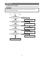
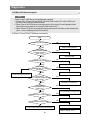
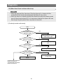
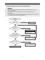
13-1) When power is not supplied
Pre-Check
1.Check if power is supplied at Concent and Power Cord is connected properly before repair
2.Check by referring to the followings.
Start
Is Power of
primery DC -TRANS applied?
(Power/Voltage)
NO
YES
Is Power of
secondary DC -TRANS applied?
(PCB CN10 �~�AC16V)
NO
YES
Check assembly of
wires and do repairing
Change DC-TRANS
Is 12V terminal
normal? (PCB V105 both terminal
Voltage)
NO
YES
Is 5V terminal
normal? (PCB V104 both termind
Voltage)
NO
YES
Are wire
connections of PANEL
PCB normal?
NO
Check PCB.REG1
(7812)/Change PCB
Check PCB.REG2
(7805) / Change PCB
Change the refrigerator Set
YES
Recheck/Change MAIN PCB ASS'Y
55
Diagnostics
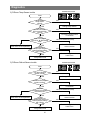
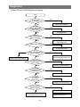
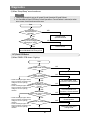
13-2) If there is a trouble with self-diagnosis
1) Ambient Sensor trouble =>(applied to Ambient Sensor Temp type)
ERROR INDICATION
Start
Is Ambient Sensor
normal?(At the top right hinge of
the refrigerator)
NO
YES
Change Ambient Sensor
Is MAIN PCB (CN31)
insertion normal?
NO
YES
Is the
connection wire
between MAIN PCB
connector (CN32)and Temp
Sensor normal (at the top
right of the
door)?
YES
Is the
voltage of Ambient
Sensor �~� of MAIN PCB
Connector (CN31)
normal?
Refer to Temp detechion
circuit sensor of the circuit
explanation.
Connector contact trouble
/re-insertion
NO
Short between connector
Sensors (Check wires
according to the change
of the door opening direction)
NO (0.5V>Measured value)
Reconfirm electric wire
connect section
YES
Is MICOM
Pin#57 input voltage
normal? (Identical Voltage
�~� of CN31)
YES
NO (0.5V>Measured value >4.5V)
Check soldering fault,short,
Lead Touch
Change PCB
56
Diagnostics
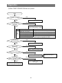
2) R-Room Temp Sensor trouble
ERROR INDICATION
Start
Is R-Room
Temp Sensor
normal?
NO
Change Temp Sensor
YES
Is the
insertion of MAIN
PCB connector(CN30)
normal?
NO
Connector contact trouble
/ re-insertion
YES
Is both trminal Voltage of
MAIN PCB �~� (BLUE-BROWN)
normal?
Refer to Temp detechion circuit
sensor of the circuit explanation.
YES
Is MICOM
Pin#51 input voltage
normal? (Identical Voltage
�~� of CN30)
NO (0.5V>Measured value)
Reconfirm electric wire
connect section
NO
Check soldering fault,short,
Lead Touch
YES
Change MAIN PCB
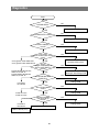
3) R-Room Defrost Sensor trouble
ERROR INDICATION
Start
Is R-Room Defrost
Sensor normal?
NO
Change Defrost Sensor
YES
Is MAIN PCB (CN30)
insertion normal?
NO
Connector contact trouble
/ re-insertion
YES
Is both trminal
Voltage of MAIN PCB Connector CN30 �~�
(PURPLE-BROWN) normal?
Refer to Temp detection circuit
sensor of the circuit explanation.
NO (0.5V>Measured value)
Reconfirm electric wire
connect section
YES
Is MICOM
Pin#54 input voltage
normal? (Identical Voltage
�~� of CN30)
YES
Change MAIN PCB
57
NO
Check soldering fault,short,
Lead Touch
Diagnostics
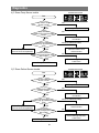
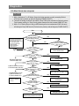
4) F-Room Temp Sensor trouble
ERROR INDICATION
Start
Is F-Room Temp
Sensor normal?
NO
Change Temp Sensor
YES
Is the insertion
of MAIN PCB connector(CN80)
normal?
NO
Connector contact trouble
/re-insertion
YES
Is both trminal voltago of
MAIN PCB �~� (Yellow-BROWN)
normal?
NO (0.5V>Measured value)
Reconfirm electric wire
connect section
YES
Refer to Temp detection circuit
sensor of the circuit explanation.
Is MICOM Pin#51
input voltage normal? Identical Voltage
�~� of CN30)
NO
Check soldering fault,short,
Lead Touch
YES
Change MAIN PCB
5) F-Room Defrost Sensor trouble
ERROR INDICATION
Start
Is F-Room Defrost
Sensor normal?
NO
Change Defrost Sensor
YES
Is MAIN PCB (CN30)
insertion normal?
NO
Connector contact trouble
/re-insertion
YES
Is both trminal Voltage of
MAIN PCB �~� (ORANGE-BROWN)
normal?
Refer to Temp detection circuit
sensor of the circuit explanation.
NO (0.5V>Measured value)
Reconfirm electric wire
connect section
YES
Is MICOM Pin#52
input voltage normal?(Identical Voltage
�~� of CN30)
YES
Change MAIN PCB
58
NO
Check soldering fault,short,
Lead Touch
Diagnostics
13-3) When COMP does not operate
Pre-Check
“Check out the COMP with the Forced Operation selected”
1. If it does not pass 5 min after a desired Temp reached,COMP does not operate.
2. During Defrost,COMP does not operate.
3. With the disconnected F-Sensor or R-Sensor,COMP does not operate because low
temperature is detected.
Start
Is Forced Operation on?
YES
Is the
MICOM #22 output
"HIGH"(5V)?
NO
Run Forced Operation
NO
YES
Is the IC70 #12
"LOW"(0.7V)?
NO
YES
Is COMP RELAY normal?
NO
Soldering checkout/
Change MICOM or PCB
Change or repair IC04/
Change PCB
YES
Is the contact
of CONNECTOR CN70
contact normal
Check RELAY /
Change PCB
YES
Insert Connector completely /
Check its connection
NO
Does
COMP ASS'Y Function
normally?
YES
NO
Change/repair COMP
Check wire assembly/connection
59
• Refer to the list (15-1)
Diagnostics
13-4) When FAN does not operate
Note
"Check out the F-FAN with the Forced Operation selected"
1. F-Room FAN, R-Room FAN and COMP COOLING FAN remains OFF while COMP is off.
(R-FAN can be on with the defrost function.)
2. When Comp is ON,R-FAN does not always remain ON (including Forced Operaation) and
when R-Room temp reaches to set temp,R-FAN remains OFF.
3. When R-Room &F-Room are closed after being opened,each FAN starts up with a delay time
(5sec ~1min) immediately.(Comp ON condition)
1) When F-Room FAN(F-FAN)does not operate
Start
Is it during Forced Operation?
NO
YES
Start Forced Operation
Does Fan
operate with DOOR S/W
presses? (Including
Delay Time)
YES
Normal R-FAN
NO
Is DOOR S/W normal?
NO
YES
Change DOOR S/W
Is the voltage
of MICOM #42 5V (Close
condition)?
NO
YES
Check soldering /Change PCB
Freezer Door Switch input #42
Is insertion of
CN71⑪PIN(YELLOW)of MAIN
PCB normal?
NO
Re-insert ConnectorCN71
YES
Is voltage
of MICOM Pin #27
"HIGH"(5V)?
NO
YES
Check soldering /Change PCB
Is voltage of IC70 #14 “LOW”(0.7V)?
NO
YES
Check IC70 /Change PCB
Is F-FAN RELAY(SSR71) normal?
Check wire assembled status/Change MAIN PCB ASS’Y
NO
Check RELAY /Change PCB
• Refer to the list (15-1)
60
Diagnostics
2) When R-Room FAN(R-FAN)does not operate
Start
Is it during
Forced Operation?
NO
YES
Start Forced Operation
Does Fan
operate with DOOR
S/W presses?(Including
Delay Time)
YES
Normal R-FAN
NO
Is the
R-Room temperature a
Fan-On condition?
NO
YES
Is DOOR S/W normal?
NO
YES
Change DOOR S/W
Is the
voltage of MICOM #43 5V
(Close condition)?
Freezer Door Switch input #43
Check temp conditions,
Select Super Cool
NO
YES
Is insertion of
CN71(W/BLUE)of MAIN
PCB normal?
Check soldering /Change PCB
NO
Re-insert ConnectorCN71
YES
Is voltage
of MICOM Pin #30
"HIGH"(5V)?
NO
YES
Check soldering /Change PCB
Is voltage
of IC70 #17
“LOW”(0.7V)?
NO
Check IC70 /Change PCB
YES
Is R-FAN RELAY
(SSR72) normal?
NO
Check RELAY /Change PCB
Check wire assembled status/
Change MAIN PCB AASS’Y
61
• Refer to the list (15-1)
Diagnostics
3) When COMP COOLING FAN does not operate
Start
Is COMP operating?
NO
Operate Forced Operation
YES
Is it COMP
COOLING FAN ON
condition?
NO
Stand by for FAN ON condition
Confirm FAN operating condition
YES
Ambient Temp Range
Higher than 71.6℉(22℃)
Comp Between 62.6℉(17℃)~69.8℉(21℃)
Fan Between 53.6℉(12℃)~69.8℉(16℃)
DELAY
Between 44.6℉(7℃)~51.8℉(11℃)
Lower than 42.8℉(6℃)
Is MICOM Pin
#28 "HIGH"(5V)?
NO
YES
Is IC3 #15
"LOW"(0.7V)?
Check soldering /Change PCB
NO
Check soldering /Change PCB
YES
Is RELAY(K74)normal?
NO
Check Relay / Change PCB
YES
Is contact of
Connector CN71� PIN (BLUE)
normal?
YES
Check wire assembled
status/Chang MAIN PCB ASS’Y
Load Operation Status
Comp Fan operates immediately upon COMP ON
Comp Fan operates in 3 min after COMP ON
Comp Fan operates in 6 min after COMP ON
Comp Fan operates in 9 min after COMP ON
Comp Fan gets off regardless of COMP
NO
Check contact of Connector
CN71 again
62
• Refer to the list (15-1)
Diagnostics
13-5) When Defrost does not operate
Pre-Check
1. With a shorted-out F or R Defrost Sensor,the fridge operates normally excepting Defrost
(The fault can be picked up with self-diagnosis,POWER ON/OFF).
2. There will be Heating trouble with a shorted-out Temp FUSE,which contributes to Defrost by natural
Temp increase resulting in a Temp Control problem stemmed from the increased COMP OFF time.
3. When a F or R Defrost Sensor is faulty as OPEN,Heating will not be terminated,and COMP will remain
off following the Temp FUSE short-off.(The fault can be picked up with self-diagnosis, POWER ON/OFF)
Start
PANEL PCB KEY
Press Super Cool and Fridge
at the same time for 5 sec.
Press any button 3 times when
the entire display blinks.
-.Once:Forced Operation
-.Twice:R Defrost
-.3 times:F/R Defrost
-.4 times:Cancel
A
Dose Defrost
start operating when F or R
Forced Defrost button
pushed?
NO
Is concerned
Defrost Sensor Temp higher
than 12 ℃?
NO
YES
YES
Is power supplied to
Defrost Heater?
Maintain Forced Operation
for a certain time
YES
Are MICOM #21 
"HIGH"(5V)?
R Defrost Heater #21
F Defrost Heater #15
R Defrost Heater IC70 #11
F Defrost Heater IC52 #17
COMMON RELAY K72
R Defrost Heater K71
F Defrost Heater K70
• Refer to the list
(15-1)
NO
Change PCB
YES
NO
Are IC70 #11 &IC52
#17 "LOW"(0.7V)?
Check IC70 &IC52 /
Change PCB
YES
Is Defrost
Heater Relay (K71,K70)
normal?
NO
Check RELAY /Change PCB
YES
Is contact of
Connector N70 normal?
NO
Check contact of Connector
CN70 again
YES
NO
Is Temp FUSE
on EVAP. normal?
Change Temp FUSE
YES
NO
Is Defrost Heater
shorted out?
YES
Check wire assembled
status/Chang MAIN PCB ASS’Y
63
Change EVAP.ASS'Y
Diagnostics
A
Does the
Function return to the normal
after Heating ?
YES
Normal
NO
Is each
concerned Defrost
Sensor Temp higher than the
terminated Temp?
NO
Standby until it reaches a
certain temperature ,Change
concerned Sensor
Refer to concerned Sensor resistance
(Appendix.Temp Sensing Circuit Table)
YES
Is the input
voltage of MICOM #54
4 higher than the voltage
upon the terminated
Temp?
Refer to concerned Sensor resistance
(Appendix.Temp Sensing Circuit Table)
R Defrost Sensor #54
F Defrost Sensor #52
YES
Change PCB
64
NO
Check temp pick-up part,
Change PCB
Diagnostics
13-6) When Alarm Sound continues without stop
Note
1. When Door gets open,Door Open alarm ("Ding Dong")goes off in 2 minutes with Door
opened.When Door remains open after this,the alarm goes off every minute.
2. When Door Switch is not pressed well,MICOM considers it as opened and alarming sound
goes off. Room Lamp becomes OFF in 10 minutes since it detects Door Open.In this case,
even though Door gets opened, Room Lamp does not comes ON.
1) If melody sounds continuously
Start
Is insertion
of MAIN PCB Connector
(CN30)normal?
NO
Contact trouble of Connector
CN30,Insert it again
YES
Does DOOR S/W
come in & out well?
NO
Repair DOOR S/W pressing
part
YES
Is DOOR S/W
good in condition?
NO
Change DOOR S/W
YES
Are MICOM #43
& #42 "HIGH"(5V)?
NO
Check DOOR S/W Circuit,
Change PCB
YES
Normal
R DOOR SIGNAL MICOM #43
OPEN :0V,CLOSE :5V
F DOOR SIGNAL MICOM #42
OPEN :0V,CLOSE :5V
65
Diagnostics
2) When “Beep Beep” sound continues
Note
1. "Beep-Beep"sounds do not go off except Forced Operation &Forced Defrost.
2. It is checkable at Panel PCB when Forced Operation or Forced Defrost is selected,so when
error occurs, check it and correct the error.
Start
Is Forced
Operation/Defrost
selected?
YES
Cancel Forced
Operation/Defrost
NO
Does buzzing
sound go off when plugging out
and plugging in again?
NO
PCB is normal
YES
Check Lead Touch &foreign substances
around PBA MAIN TEST/Change PCB
13-7) Panel PCB Defect
1) When PANEL PCB doesn 't light up
Start
Is PANEL PCB normal?
NO
YES
Change PANEL PCB
Is insertion of PANEL PCB
Connector normal?
• Check the left/right upper cabinet
YES
hinge connection according to the
change of the door opening
Is insertion of
direction.
PANEL PCB(CN50) Connector
• Check the left/right upper door
normal?
hinge connection according to the
change of the door opening
YES
direction.
Is insertion of
Upper Hinge Cover Connector
normal?
• Check the left/right upper cabinet
YES
hinge connection according to the
change of the door opening
Is MAIN PCB 12V normal? (REG1)
direction.
• Check the left/right upper door
hinge connection according to the
change of the door opening
direction.
No Problem / Re-Check
66
NO
Re-insert PANEL PCB
Connector, Check contacts
NO
Re-insert MAIN PCB
Connector, Check contacts
NO
NO
Re-insert Connector,
Check contacts
Check REF(7812) part /
Change PCB
Diagnostics
2) When PANEL PCB Buttons do not work
Start
Is Connector
of Upper Hinge Cover inserted
well?
NO
YES
Is insertion
of MAIN PCB Connector (CN50)
normal?
NO
YES
Is insertion
of PANEL PCB Connector
normal?
NO
YES
Is there any
of 6 buttons pressed?
NO
YES
YES
Is CHILD LOCK BUTTON
pressed?
Re-insert Connector,
Check contacts
Re-insert MAIN PCB
Connector, Check contacts
Re-insert PANEL PCB
Connector, Check contacts
Re-assemble PANEL PCB
COVER
Release CHILD LOCK
YES
Recheck/Change MAIN PCB ASS'Y
13-8) When Room Lamp does not light up(F &R Rooms are the same)
1) When F &R Room Lamps do not light up
Pre-Check
- Room Lamp(F,R)
1. Check F-Room Lamp ON after opening Freezer Door.
2. Check F-Room Lamp OFF by pushing Door S/W.
3. Check R-Room with using the same method �,� after closing Freezer Door.
4. When it’s problems, check Room Lamp and Door S/W (Refer to Door S/W sensor circuit)
5. Check the electric wire connect status.
67
Diagnostics
Start
YES
Is DOOR OPEN?
NO
DOOR OPEN
YES
Is DOOR SWITCH normal?
NO
Change DOOR SWITCH
YES
Is Room LAMP(R,F)
normal?
NO
Change LAMP
Is the contact
state of connector CN70 & CN71
normal?
CN70 � PIN;F LAMP WIRE PINK
CN71 � PIN;R LAMP WIRE BLACK
Re-check the ccutact of the
connector CN70 & CN71
YES
Are the
voltages of MICOM #42 &
#43 for DOOR SWITCH
normal?
R DOOR SIGNAL MICOM #43
OPEN :0V,CLOSE :5V
F DOOR SIGNAL MICOM #42
OPEN :0V,CLOSE :5V
FLA MP#24
RLA MP#29
Check connector CN30,
soldering & short/Change PCB
Are MICOM #24 
"HIGH"(5V)?
NO
Change PCB
YES
NO
Change PCB
YES
Are lamp controlling
relay (K73 &K75)
normal?
FLA MPK73
RLA MPK75
NO
YES
Are IC70 #13 
"LOW"?
F LAMP IC70 #13
F LAMP IC70 #16
NO
YES
NO
Change PCB
Normal / Re-check
• Refer to the list (15-1)
68
13-9) When Ice Water Valve does not operate (Option)
Pre-Check
1. While disassembling,make sure to cut off water since the ice water valve is directly
connected with water.
2. Make sure to avoid the electric shock while disassembling because one end of wire is
applied with power.
3. Check the operation of the ice water valve only after the ice maker test switch is pressed.
(F-Room Ice Maker)
ICE WATER VALVE
OPERATION CHECK
Is the
confirming sound of
the valve operation heard when
Ice Maker Test S/W
pushed?
NO
Normal (check the
ice water valve hose)
YES
Does Main
PCB MICOM #31
have high (+5V)output?
NO
Check short-out
Soldering / PCB change
YES
Does Main PCB IC70 #18
have low (0V)output?
NO
Soldering short
check/PCB change
YES
- Reference
* Load terminal
check-up method
Is the contact
point of main PCB RELAY
K71 normal?
NO
Soldering short
check/PCB change
YES
Main PCB Normal
- Check other parts
① Wire between ice water value
and main PCB
② Water Value defect or Connector
contact defect
③ Check Connection Hose defect
69
13-10) When Ice Maker does not operate (Option:Model installed)
Pre-Check
1. Water is automatically supplied to the Ice Maker and it dispenses cubed or crushed ice
according to its setting.
2. Power is applied to one of its wires.So,be sure to refer to its exploded view when
disassembling.
3. To check the operation of the Ice Maker,press the Ice Maker Test S/W.(F-Room Ice Maker) It
is not possible to check with the power disengaged.
Ice Check
YES
Does Ice come
out normally?
Normal
NO
Does it
rotate with the Ice
Maker Test S/W
pressed?
YES
Check wires and Ice Maker Sensor
NO
- Refer to Sensor Voltage Table
of Thermistor Circuit
Is the voltage
at PBA MAIN CN90
�~� more than 11V with
the Ice Maker Test S/W
pressed?
YES
Press Test S/W
again/Replace Ice Maker
NO
Is voltage
applied to IC90 PIN #7
(DC11~12v)?
NO
Check Transformer or Other
Power Related Circuits
YES
Replace PCB
70
14 . Illustrated Parts Catalog.
14-1) Freezer
RI071
R M 001
RI095
R F031
R M 010
RI096
RI080
RI081
R M 01 7
R M 001
RI021
R W4 33
R S 090
R W 648
R F069
R H 029
R M 00 3
R F070
R F00 2
R F081
R F00 4
R F050
R F011
R S 08 7
RI074
R F001
R F067
R F026
R F068
R F010
R H 029
R W 648
R F079
R F010
R F051
R F036
R W 394
RI08 5
R F00 6
71
Illustrated Parts Catalog.
■ Parts List of Freezer
NO
CODE-NO
RF011
RS087
RI074
RF026
RF004
DA97-00192F
DA32-00006C
DA47-00095E
DA97-00195D
DA97-02790A
DA97-02793A
DA97-02793B
DA61-02165A
DA61-02166A
DA63-02523A
DA66-00328A
DA66-00348A
DA66-10104A
DA71-20145A
DA97-02797A
DA97-02797B
DA61-02163A
DA61-02164A
DA63-02524A
DA66-00329A
DA66-00347A
DA66-10104A
DA71-20145A
DA97-02798A
DA97-02799A
DA31-00002V
DA31-00019A
DA61-00081B
DA63-00771A
DA63-02567A
DA97-02800A
DA97-02800B
4713-001173
DA32-10105S
DA47-00112H
DA61-02167A
DA61-02168A
DA63-02522A
DA63-02569A
DA63-40006A
DA97-02203E
DA61-01800A
DA61-01805A
DA61-02183A
DA63-02183A
DA63-02529A
DA97-00258E
DA63-02525A
RF002
RF069
RF070
RF050
RF002
RW648
RH029
RF001
RF067
RF068
RF051
RF001
RW648
RH029
RF006
RF010
RF038
RI085
RF036
RW394
RF010
RI071
RI081
RS090
RI080
RI095
RI096
RF031
RW374
RM001
RM017
RW433
RM010
RI021
RM012
RM001
RM003
OPTION
PART NAME
RB195BSSB RB195BSSW RB195BSVQ RB195BSBB RB215BSSB RB215BSSW RB215BSVQ RB215BSBB
ASSY-EVAP FRE
SENSOR ASSY
THERMO FUSE-ASSY
ASSY-PLATE DRAIN,FRE
ASSY TRAY-ICE CUBE
ASSY-WIRE BASKET UPP
GUIDE-BASKET UPP L
GUIDE-BASKET UPP R
COVER-WIRE BASKET UPP
WIRE-BASKET UPP
ROLLER-FRE
FIXER-ROLLER
ASSY-WIRE BASKET LOW
GUIDE-BASKET LOW L
GUIDE-BASKET LOW R
COVER-WIRE BASKET LOW
WIRE-BASKET LOW
ROLLER-FRE
FIXER-ROLLER
ASSY COVER EVAP-FRONT FRE
ASSY COVER EVAP-REAR FRE
MOTOR FAN
FAN-PROPELLER
CASE-MOTOR
GROMMET-FAN MOTOR
COVER-EVAP REAR
ASSY-SUPT FRE
LAMP-INCANDESCENT
SENSOR ASSY
LAMP HOLDER
SUPPORT-FRE L
SUPPORT-FRE R
●
●
●
●
●
●
●
●
●
●
●
●
●
●
●
●
●
●
●
●
●
●
●
●
●
●
●
COVER LAMP-FRE
●
●
●
●
●
●
GROMMET
ASSY ICE MAKER-MECH
FIXER-SENSOR
GUIDE ICE-FULL
SUPPORT-ICE MAKER
COVER-SENSOR
TRAY ICE
ASSY ICE MAKER
COVER-ICE MAKER
●
●
●
●
●
●
●
●
●
72
●
●
●
●
●
●
●
●
●
●
●
●
●
●
●
●
●
●
●
●
●
●
●
●
●
●
●
●
●
●
●
●
●
●
●
●
●
●
●
●
●
●
SPEC
Illustrated Parts Catalog.
14-2) Fridge
RI074
R S 087
RI015
RI081
RI07 8
RI00 8
R F037
R W 394
RI00 8
RI085
R F038
R S 091
R W 74 2
RI04 1
RI035
RI036
RI018
R W 829
RI021
RI040
RI99 7
R W 648
RI091
R F00 5
R H 029
RI99 8
RI99 8
RI030
RI010
R W 648
R H 029
RI010
73
Illustrated Parts Catalog.
■ Parts List of Fridge
NO
CODE-NO
RI081
RI078
4713-001197
DA63-00925B
DA61-00761B
DA61-00760B
DA67-40250E
DA47-00095D
DA32-00006C
DA97-00296L
DA97-00296M
DA97-00441B
DA97-00459N
DA31-00003N
DA31-00016A
DA32-10105T
DA63-00183B
DA63-00771A
DA63-00932A
DA63-00933B
DA63-0093A
DA97-00663C
DA97-00663D
DA64-00449B
DA64-00448B
DA97-00664E
DA97-00664F
DA61-00368B
DA61-00367B
DA61-00370B
DA61-00369B
DA61-01795B
DA97-00664G
DA97-00664H
DA97-00681E
DA97-00681F
DA61-00759B
DA61-00762B
DA63-01270B
DA66-10104A
DA71-20145A
RI030
RW829
RI074
RS087
RI018
RI015
RI008
RF038
RI085
RS091
RF037
RW394
RI008
RF005
RI021
RI997
RI091
RI041
RI035
RI036
RW742
RI040
RI998
RI998
RI010
RW648
RH029
OPTION
PART NAME
RB195BSSB RB195BSSW RB195BSVQ RB195BSBB RB215BSSB RB215BSSW RB215BSVQ RB215BSBB
LAMP-INCANDESCENT
COVER-LAMP,REF
●
●
●
RAIL-VEG, MID
TRAY-UTILITY
THERMO FUSE-ASSY
SENSOR ASSY
ASSY TRAY-CHILLED ROOM
ASSY DRAIN-PLATE,REF
ASSY COVER EVAP-REF
MOTOR FAN
FAN-CIRCUIT
SENSOR ASSY
COVER-MOTOR
GROMMET-FAN MOTOR
COVER-EVAP RE,REF
COVER-EVAP FR,FRE
COVER-SENSOR
●
●
●
●
●
●
●
●
●
●
●
●
●
●
●
ASSY COVER-VEG
●
●
●
●
●
●
●
●
●
●
●
●
●
●
●
●
●
●
●
TRIM-COVER VEG
●
●
ASSY SHELF REF-UPP
●
●
RAIL-CHILLED, L
●
●
RAIL-CHILLED, R
SUPPORT-CHILLED
●
●
ASSY SHELF REF-MID
●
●
●
●
ASSY CASE VEG
●
●
CASE-VEG, REF
COVER-VEG REF
ROLLER-FRE
FIXER-ROLLER
●
●
●
74
●
●
●
●
SPEC
Illustrated Parts Catalog.
14-3) Door of Refrigerator
RE0 58
20
RE0 62
RE001
RE0 63
RE0 21
RE0 25
R D 025
R D 025
R O 052
RE0 43
R O 11 6
R O 058
R D 001
RE0 53
R O 11 6
RE0 43
RE0 43
75
Illustrated Parts Catalog.
■ Parts List of Refrigerator Door
NO
RE001
RE043
RO116
RD001
RE043
RE043
RO116
RE053
RE021
RE024
RE024
RE025
RD025
RO052
RD025
RE058
RO058
CODE-NO
DA91-02052A
DA91-02052B
DA90-02052C
DA90-02052D
DA61-02158A
DA63-02516A
DA91-02051A
DA91-02051B
DA91-02051C
DA91-02051D
DA61-02157A
DA61-02158A
DA63-02516A
DA63-01052A
DA61-00365C
DA63-00926B
DA63-00927B
DA63-01263C
DA97-02788A
DA97-02788B
DA97-02788C
DA41-00264A
DA63-02518A
DA63-02518B
DA63-02518C
DA63-02517A
DA67-01230A
OPTION
PART NAME
RB195BSSB RB195BSSW RB195BSVQ RB195BSBB RB215BSSB RB215BSSW RB215BSVQ RB215BSBB
●
●
●
ASSY DOOR FOAM REF
●
●
●
●
STOPPER-MID
GROMMET HINGE
●
●
●
●
●
●
●
●
ASSY DOOR FOAM FRE
●
●
●
●
STOPPER-DOOR LOW
STOPPER-MID
GROMMET HINGE
GASKET DOOR-SUB,FRE
GUIDE BOTTLE
GUARD-REF UPP,L
GUARD-REF UPP,R
GUARD-REF LOW
●
●
●
●
●
●
●
●
●
●
●
●
●
●
●
●
●
●
●
●
●
ASSY COVER-CONTROL PANEL
●
●
●
PBA PANEL
●
●
●
●
COVER-CONTROL PANEL
●
●
76
●
●
●
COVER-CAP DOOR REF UPP
CAP-HANDLE
●
●
●
●
●
●
SPEC
Illustrated Parts Catalog.
14-4) Cabinet
RO0 05
RO0 48
RO0 66
RO0 07
RO0 50
R F018
R F059
RO0 04
RO 120
RO0 40
R F025
RO 11 9
RO0 89
RO0 45
R H 00 3
RO0 90
RO0 40
R F038
R W 011
R W3 90
R H 008
R W 903
R W3 91
R H 023
R H 00 1
R W 139
RO 11 7
R I076
RO0 39
RO0 03
R W 00 7
RO0 36
R H 021
R H 00 2
R H 014
R H 00 5
R E 04 6
RO0 01
R H 00 6
R W 931
R H 011
R H 019
77
R H 004
Illustrated Parts Catalog.
■ Parts List of Cabinet
NO
CODE-NO
RO001
RO036
RE046
DA61-01051B
DA61-02162A
DA64-20138B
DA63-02530B
DA63-02530A
DA63-02530C
DA63-02531B
DA63-02531A
DA63-02531C
DA63-02520A
DA63-02520B
DA63-02520C
DA63-02521A
DA63-02521B
DA63-02521C
DA67-00178A
DA97-02782A
DA97-02783A
DA62-00633G
DA62-00930A
DA99-00240D
DA97-00979A
DA97-00209H
DA63-02469A
2501-001045
DA26-00022B
DA31-00010E
DA34-10003D
DA34-10122D
DA35-10013N
DA39-20389E
DA41-00293A
DA61-00758A
DA61-01957A
DA62-20001Q
DA63-00951A
DA63-01866A
DA63-02533A
DA63-40171D
DA73-30102B
DA97-00278A
DA62-20001Q
DA63-00951B
DA97-00408D
DA60-90146A
DA61-40126B
DA97-00921A
DA97-02792A
DA31-10110G
DA63-02205A
MK172CL2U/E08
RO117
RO003
RO044
RO045
RW139
RO040
RO039
RO090
RO089
RO120
RO119
RF018
RF025
RO004
RO066
RF038
RH005
RI076
RH006
RW931
RO007
RO048
RH021
RW903
RW390
RH004
RO048
RH023
RH014
RW011
RW903
RW391
RH001
RH019
RH011
RW007
RH003
RH008
RH022
RH002
OPTION
PART NAME
RB195BSSB RB195BSSW RB195BSVQ RB195BSBB RB215BSSB RB215BSSW RB215BSVQ RB215BSBB
FOOT-FRONT
HINGE-LOW
TRIM-PLATE ABSORBER
●
●
●
●
●
●
●
●
●
●
COVER HINGE-LOW
●
●
●
●
●
●
●
●
COVER LEG-FRONT
●
●
●
●
●
●
●
●
COVER HINGE-UPP L
●
●
●
●
●
COVER HINGE-UPP R
78
●
●
●
●
CAP DOOR-S/W
ASSY HINGE UPP
ASSY HINGE MID
PIPE-WATER LINE
VALVE WATER-ONE WAY FITTING
ASSY PACKING-SUB
ASSY COVER-PIPE WATER
ASSY PIPE-WATER
GROMMET-PIPE WATER FILL IN
C-OIL
TRANS POWER
FAN-ASSY
RELAY PROTECTOR O/L
SWITCH-DOOR
RELAY-PTC
WIRE HARNESS-EARTH
PBA MAIN
CASE-PCB PANEL
CLIP-DRYER
TUBE PVC
GROMMET-DRAIN,HOSE
COVER RELAY
COVER PCB-PANEL
GROMMET-SUCT PIPE
DRYER-ASSY
ASSY TUBE-DRAIN
TUBE PVC
GROMMET-DRAIN,HOSE
ASSY COVER-COMP
PIN-CASTER
CASTER-REAR
ASSY PIPE-SUCT
ASSY TRAY-DRAIN WATER
MOTOR CIRCUIT
GROMMET-SUB CONDENSER
COMPRESSOR
●
●
●
●
●
●
●
●
●
●
●
●
●
●
●
●
●
●
●
●
●
●
●
●
●
●
●
●
●
●
●
●
●
●
●
●
●
●
●
●
●
●
●
●
●
●
●
●
●
●
●
●
●
●
●
●
●
●
●
●
●
●
●
●
●
●
●
●
●
●
●
●
●
●
●
SPEC
SAFETY PRECAUTIONS FOR AS
● Upon electronic Control system repair/change,make sure the set unplugged.
� Be ware of electric shock.
● Use rated electronic Control equipment.
� Make sure to check out ModeL name,Rated voltage,Rated current,Operation Temp,etc.
● Upon repair,make sure that harnesses are not to be water-penetrated and are bundled tight.
� Should not be detached by a certain amount of external force.
● Upon repair,completely remove dust or other foreign substances from housing,harness,
connector,etc.
� To prevent fire by tracking,short,etc.
● Check out whether water has penetrated into the electronic Control system.
� If there is any kind of trace,take necessary measures such as related component change,
insulation tapping,etc.
● After repair,check out the assembled state of parts.
� It should be the same as the previous state.
● Check out the surrounding conditions.
� Change the location,if the fridge is located at humid,wet places or the installed state is unstable.
● If needed,ground the fridge.
� Especially,if there is a possibility of electric leakage,ground is indispensable.
● Do not allow consumers to overload a certain outlet.
● Check out whether the power cord or the outlet is broken,squeezed,chopped off or heatdeformed.
� Repair or replace the defective power cord/outlet immediately.
� Make sure the power cord is not punctuated or stomped down.
● Do not allow consumers to keep food unstable or place bottles in the Freezer Room.
● Do not allow consumers to repair the fridge for themselves.
● Do not allow consumers to keep things except for food.
� Pharmaceutical,Chemical substances :These are not possible to be fine-Controlled with a
consumer fridge.
� Flammable material (alcohol,benzene,ether,LPG,etc):possibility of explosion.
79
15. REFERENCE
15-1) Reference (Measure Load Terminals)
* Turn off Power, disassemble Housing connected to MAIN PCB CN70,71 and measure followings
LOAD
MEASURING
TERMINALS
PCB MAIN
1) F DEFROST HEATER
2) F DRAIN HEATER
CN70
⑬&⑦
1)R DEFROST HEATER
2)ICE WATER PIPE HEATER
CN71
⑨&⑦
ICE WATER VALVE
CN71
①&⑤
F FAN MOTOR
CN71
⑪&⑤
R FAN MOTOR
CN71
③&⑤
COMP. FAN MOTOR
CN71
⑨&⑤
R LAMP
CN71
⑦&⑤
F LAMP
CN70
①&⑪
VALUE
0Ϊ
�Ϊ
0Ϊ
�Ϊ
0Ϊ
�Ϊ
0Ϊ
�Ϊ
0Ϊ
�Ϊ
0Ϊ
�Ϊ
0Ϊ
�Ϊ
0Ϊ
�Ϊ
DEFECTS
THERMAL FUSE,HEATER,WIRE SHORT
THERMAL FUSE,HEATER,WIRE CUT
THERMAL FUSE,HEATER,WIRE SHORT
THERMAL FUSE,HEATER,WIRE CUT
COIL,WIRE SHORT
COIL,WIRE CUT
MOTOR,WIRE SHORT MOTOR,WIRE
CUT,HOUSING SLIPPED AWAY
MOTOR,WIRE SHORT MOTOR,WIRE
CUT,HOUSING SLIPPED AWAY
MOTOR,WIRE SHORT MOTOR,WIRE
CUT,HOUSING SLIPPED AWAY
LAMP,WIRE SHORT LAMP,WIRE
CUT,HOUSING/LAMP SLIPPED AWAY
LAMP,WIRE SHORT LAMP,WIRE
CUT,HOUSING/LAMP SLIPPED AWAY
80
OTHERS
VALUE FOR
NORMAL HETAER
VALUE FOR
NORMAL MOTOR
VALUE FOR
NORMAL MOTOR
VALUE FOR
NORMAL MOTOR
VALUE FOR
NORMAL MOTOR
VALUE FOR
NORMAL MOTOR
VALUE FOR
NORMAL MOTOR
VALUE FOR
NORMAL MOTOR
* Turn on Power and check status of Relay &Driving Circuit by checking followings according to load operation .
3-CONTACT 3-CONTACT
NO
C
NC
PCB
Note) NC →NORMAL CLOSE
(C-TERMINAL & ON-TERMINAL)
NO →NORMAL OPEN
(C-TERMINAL & OPEN-TERMINAL)
C →COMMON TERMINAL
CN70
COIL TERMINAL
TEIGER
COIL
TERMINAL
OPERATION
Measure after
separating
RELAY TERMINALS
K70
R,F DEFROST &
COMP OFF
CN71
K71
K72
K70
COMP ON
K71
K72
R DEFROST ON K71
K72
K70
F DEFROST ON
K72
F FAN ON R FAN SSR71
ON C FAN ON SSR72
K74
ICE WATER
K76
VALVE ON R
K75
LAMP ON
K73
F LAMP ON
CN70 ⑪-⑬
CN70 ⑪-⑨
CN70 ⑤-③
CN70 ⑪-⑬
CN70 ⑪-⑨
CN70 ⑤-③
CN70 ⑪-⑬
CN70 ⑪-⑨
CN70 ⑤-③
CN71 ⑬-⑨
CN71 ⑪-CN70 ③
CN71 ③-CN70 ③
CN71 ⑨-CN70 ③
CN71 ①-CN70 ③
CN70 ①-③
CN71 ⑦-CN70 ③
VALUE
WHEN IT IS DIFFERENT FROM MEASURED VALUE
SUPPLY
VOLTAGE (SV)
SV
SV
5~30V
5~30V
0V
0V
SV
0V
SV
0V
0V
0V
0V
0V
0V
K70 CONTACT SHORT,FAULTY DRIVING CIRCUIT
K71 CONTACT SHORT,FAULTY DRIVING CIRCUIT
K72 NO CONTACT SHORT,FAULTY DRIVING CIRCUIT
FAULTY K70 OR K72 NC CONTACT SHORT,FAULTY DRIVING CIRCUIT
FAULTY K71 OR K72 NC CONTACT SHORT,FAULTY DRIVING CIRCUIT
K72 NO CONTACT OPEN,FAULTY DRIVING CIRCUIT
FAULTY K71,K72 NC CONTACT OPEN,FAULTY DRIVING CIRCUIT
K72 NO CONTACT SHORT,FAULTY DRIVING CIRCUIT
K70 CONTACT SHORT,FAULTY DRIVING CIRCUIT
K72 NO CONTACT SHORT,FAULTY DRIVING CIRCUIT
SSR71 OPEN,FAULTY DRIVING CIRCUIT
SSR72 OPEN,FAULTY DRIVING CIRCUIT
K74 NO CONTACT OPEN,,FAULTY DRIVING CIRCUIT
K76 NO CONTACT SHORT,FAULTY DRIVING CIRCUIT
K75 NO CONTACT OPEN,FAULTY DRIVING CIRCUIT(DOOR SWITCH)
K73 NO CONTACT SHORT,FAULTY DRIVING CIRCUIT(DOOR SWITCH)
81
15-2) Reference (Measure Sensor Terminals)
* Check after disassembling connected to MAIN PCB CN30&CN32
* Because it is NTC TYPE Sensor,risistance decreases as temp increases
1. Measure resistance between CN30 ⑦ and ⑥ for R-Sensor.
2. Measure resistance between CN30 ② and ③ for F-Sensor.
3. Measure resistance between CN30 ⑧ and ⑥ for R Defrost Sensor.
4. Measure resistance between CN30 ② and ④ for F Defrost Sensor.
5. Measure resistance between CN31 ① and ④ for Ambient Sensor.
6. Compare the above values with current temps of Sensor locations
(21.Temp Sensing Circuit Table)and Part Spec in Manual and evaluate them.
15-3) Others (Measure Load Terminals)
NO
1
2
ITEM
PBA MAIN
PBA PANEL
3
TRANS DC
4
SENSOR
SPEC
05 W2 PBA MAIN
05 W2 PBA PANEL,BLUE
115V/60Hz
220V/50,60Hz
127V/60Hz
230V/60Hz
F DEFROST SENSOR
R DEFROST SENSOR
F SENSOR
R SENSOR
AMBIENT SENSOR
CODE NO
DA41-00293A
DA41-00264A
DA26-00022B
DA26-00022C
DA26-00022D
DA26-00022E
DA32-00006C
DA32-00006C
DA32-10105S
DA32-10105T
DA32-00011L
REMARK
- The second part (DA41-XXXXX?)of CODE for MAIN PCB ASS'Y PART may change according to
MICOM or Option change,so check it when asking for parts.
82
16. PCB DIAGRAM
⑧
⑫
⑩
⑪
⑥
②
⑨
⑤⑦
③
④
①
1. AC is input via Connector CN10 and DC12V,5V and GND are supplied via Regulator.
2. Oscillator generating clocks required for the MICOM program control &Reset circuit initializing
programs upon power on/off.
3. EEPROM:It stores data.
4. It receives various sensor signals such as F/R Door S/W On/Off and sends them to MICOM after
filtering their noises.
5. PLC (Power Line Communication)Circuit
6. Buzzer Circuit
7. Circuit for model classifying options
8. It is the display driving part controlling the LEDs and the button signals.
9. It carries out the Ice Maker operation,supplies power to the motor and detects the S/W on/off.
10. It is Relay controlling AC load and operates by receiving drive signals through IC ⑪.
11. Relay Driver IC
12. AC connector
83
F LAMP
COMMON LINE(N)
COMP
HEATER COMMON LINE(N)
R HEATER (R DRAIN. ICE WATER PIPE)
HEATER COMMON LINE(L)
F HEATER (F DRAIN)
①ICE WATER VALVE
③R FAN
⑤COMMON LINE(L)
⑦R LAMP
⑨C FAN
⑪F FAN
①
③
⑤
⑦
⑨
⑪
⑬
① PANEL PCB WIRE
③ PANEL GRID SIGNAL
⑤ KEY
①,② ICE MAKER MOTOR
③ GND
④ ICE EJECT SENSOR
⑤ TEST S/W
⑥ HORIZONTAL S//W
⑦ ICE FULL S//W
⑧ GND
①
②
③
④
⑤
⑥
⑦
⑧
F-DOOR S/W
GND
F-ROOM SENSOR
F-DEFROST SENSOR
R-DOOR S/W
GND
R-ROOM SENSOR
R-DEFROST SENSOR
①TRANS IN AC
③TRANS IN AC
① AMBIENT
SENSOR
④ GND
17. CONNECTOR ARRANGEMENT&DESCRIPTIONS
84
85
DOOR SWITCH
R DOOR SWITCH
F DOOR SWITCH
DRIVING PART
R ROOM LAMP
F ROOM LAMP
ICE WATER VALVE
R ROOM FAN
F ROOM FAN
COMPRESSOR COOL FAN
AC COMPRESSOR
R DEF HEATER
+
R DRAIN HEATER
+
ICE WATER PIPE HEATER
F DEF HEATER
+
F DRAIN HEATER
DOOR CONTROL
DRIVING PART CONTROL
POWER CONTROL
AC/DC POWER CIRCUIT
TRANSFORMER
AMBIENT SENSOR
SENSOR
R DEF SENSOR
F DEF SENSOR
R ROOM SENSOR
BUZZER CIRCUIT
MOTOR
EJECT
ICE MAKER KIT
FULL SWITCH
HORIZONTAL
SWITCH
TEST SWITCH
EEPROM
OSCILLATOR CIRCUIT
PANEL PCB
BUTTON INPUT
LED DISPLAY
DISPLAY CONTROL
CIRCUIT
BUTTON CONTROL
DISPLAY MODE CONTROL
RESET CIRCUIT
UART COMMUNICATION CONTROL
BUZZER CONTROL
EEPROM CONTROL
EJECTJING MOTOR OVERLOAD SWITCH MOTOR
SENSOR CIRCUIT DETECTION DETECTION CONTROL
ICE MAKER CONTROL CIRCUIT
ICE MAKER CONTROL
STATUS CONTROL
NORMAL MODE CONTROL
TEST MODE CONTROL
OPTION CIRCUIT
EJECTING SENSOR
SENSOR
DETECTION CIRCUIT
AD CONVERT CONTROL
F ROOM SENSOR
DOOR S/W
DETECTION CIRCUIT
DRIVING
PART
CONTROL
CIRCUIT
MAIN PCB
AC POWER INPUT
POWER CORD
AC100~240V
18. BLOCK DIAGRAM
86
OPTION CIRCUIT
DOOR S/W
DEFECTION CIRCUIT
SENSOR DETECTION CIRCUIT
DRIVING PART
CONTROL CIRCUIT
AC/DC
POWER CIRCUIT
BUZZER CIRCUIT
RESET CIRCUIT
OSCILLATOR CIRCUIT
EEPROM
CONTROL CIRCUIT
ICE MAKER
CONTROL CIRCUIT
DISPLAY
CONTROL CIRCUIT
19. CIRCUIT DIAGRAM
20. WIRING SCHEMATIC
87
21. Temp to Resistance of Sensor &MICOM PORT Voltage
Sensor CHIP:PX41C Standard
℃
-50
-49
-48
-47
-46
-45
-44
-43
-42
-41
-40
-39
-38
-37
-36
-35
-34
-33
-32
-31
-30
-29
-28
-27
-26
-25
-24
-23
-22
-21
-20
-19
-18
-17
-16
-15
-14
-13
-12
-11
-10
-9
-8
-7
-6
℉
-58
-56.2
-54.4
-52.6
-50.8
-49
-47.2
-45.4
-43.6
-41.8
-40
-38.2
-36.4
-34.6
-32.8
-31
-29.2
-27.4
-25.6
-23.8
-22
-20.2
-18.4
-16.6
-14.8
-13
-11.2
-9.4
-7.6
-5.8
-4
-2.2
-0.4
1.4
3.2
5
6.8
8.6
10.4
12.2
14
15.8
17.6
19.4
21.2
V
4.694
4.677
4.659
4.641
4.622
4.602
4.581
4.560
4.537
4.514
4.490
4.465
4.439
4.412
4.385
4.356
4.326
4.296
4.264
4.232
4.199
4.165
4.129
4.093
4.056
4.018
3.980
3.940
3.899
3.858
3.816
3.773
3.729
3.685
3.640
3.594
3.548
3.501
3.453
3.405
3.356
3.307
3.258
3.208
3.158
Ϊ
153319
144794
136798
129294
122248
115631
109413
103569
98073
92903
88037
83456
79142
75077
71246
67634
64227
61012
57977
55112
52406
49848
47431
45146
42984
40938
39002
37169
35433
33788
32230
30752
29350
28021
26760
25562
24425
23345
22320
21345
20418
19537
18698
17901
17142
℃
-5
-4
-3
-2
-1
0
1
2
3
4
5
6
7
8
9
10
11
12
13
14
15
16
17
18
19
20
21
22
23
24
25
26
27
28
29
30
31
32
33
34
35
36
37
38
39
℉
23
24.8
26.6
28.4
30.2
32
33.8
35.6
37.4
39.2
41
42.8
44.6
46.4
48.2
50
51.8
53.6
55.4
57.2
59
60.8
62.6
64.4
66.2
68
69.8
71.6
73.4
75.2
77
78.8
80.6
82.4
84.2
86
87.8
89.6
91.4
93.2
95
96.8
98.6
100.4
102.2
V
3.107
3.057
3.006
2.955
2.904
2.853
2.802
2.751
2.700
2.649
2.599
2.548
2.498
2.449
2.399
2.350
2.301
2.253
2.205
2.158
2.111
2.064
2.019
1.974
1.929
1.885
1.842
1.799
1.757
1.716
1.675
1.636
1.596
1.558
1.520
1.483
1.447
1.412
1.377
1.343
1.309
1.277
1.253
1.213
1.183
88
Ϊ
16419
15731
15076
14452
13857
13290
12749
12233
11741
11271
10823
10395
9986
9596
9223
8867
8526
8200
7888
7590
7305
7032
6771
6521
6281
6052
5832
5621
5419
5225
5039
4861
4690
4526
4369
4218
4072
3933
3799
3670
3547
3428
3344
3204
3098
℃
40
41
42
43
44
45
46
47
48
49
50
51
52
53
54
55
56
57
58
59
60
61
62
63
64
65
66
67
68
69
70
71
72
73
74
75
76
77
78
79
80
81
82
83
84
℉
104
105.8
107.6
109.4
111.2
113
114.8
116.6
118.4
120.2
122
123.8
125.6
127.4
129.2
131
132.8
134.6
136.4
138.2
140
141.8
143.6
145.4
147.2
149
150.8
152.6
154.4
156.2
158
159.8
161.6
163.4
165.2
167
168.8
170.6
172.4
174.2
176
177.8
179.6
181.4
183.2
V
1.153
1.124
1.095
1.068
1.040
1.014
0.988
0.963
0.938
0.914
0.891
0.868
0.846
0.824
0.803
0.783
0.762
0.743
0.724
0.706
0.688
0.670
0.653
0.636
0.620
0.604
0.589
0.574
0.560
0.546
0.532
0.519
0.506
0.493
0.481
0.469
0.457
0.446
0.435
0.424
0.414
0.404
0.394
0.384
0.375
Ϊ
2997
2899
2805
2714
2627
2543
2462
2384
2309
2237
2167
2100
2036
1973
1913
1855
1799
1745
1693
1642
1594
1547
1502
1458
1416
1375
1335
1297
1260
1225
1190
1157
1125
1093
1063
1034
1006
978
952
926
902
877
854
832
810
272, Oseon-Dong, Kwangsan-Gu,
Kwangju-City, Korea, 506-253
TEL : 82-62-950-6810, 6811
FAX : 82-62-950-6829
© Samsung Electronics Co., Ltd.
Refrigerator Division 2006. 05
Printed in Korea