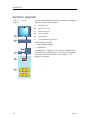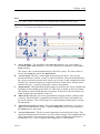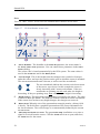
1
Operator manual
Simrad PI50
Catch monitoring system
www.simrad.com
TECHNOLOGY
FOR
SUSTAINABLE
FISHERIES
Simrad PI50
Operator manual
Release 1.0.1
This manual provides you with the basic information
required to operate the Simrad PI50. For a more detailed
description of the operation and functionality, including
menus and all parameters, refer to the Simrad PI50
Reference manual.
328457/A
09.11.2010
©
Kongsberg Maritime AS
Revision status
Document: 328457 / ISBN-13: 978-82-8066-121-0 / Rev.A
Rev.A
09.11.2010
First release with SW version 1.0.1.
License information
When you have obtained the necessary licenses to operate the PI50, we strongly advice that you
write down the hardware ID and the license codes on this page.
Function
Purpose
Hardware ID:
N/A
Code
License code
License code
License code
Copyright
©2010 Kongsberg Maritime AS
The information contained in this document remains the sole property of Kongsberg Maritime AS. No part
of this document may be copied or reproduced in any form or by any means, and the information contained
within it is not to be communicated to a third party, without the prior written consent of Kongsberg
Maritime AS. The document, or any part of it, may not be translated to any other language without the
written approval from Kongsberg Maritime AS.
Disclaimer
Kongsberg Maritime AS endeavours to ensure that all information in this document is correct and fairly
stated, but does not accept liability for any errors or omissions.
Warning
The equipment to which this manual applies must only be used for the purpose for which it
was designed. Improper use or maintenance may cause damage to the equipment and/or injury
to personnel. The user must be familiar with the contents of the appropriate manuals before
attempting to install, operate or work on the equipment.
Kongsberg Maritime AS disclaims any responsibility for damage or injury caused by improper
installation, use or maintenance of the equipment.
Support information
If you require maintenance or repair, contact your local dealer. You can also contact us using the
following address: [email protected]. If you need information about our other products, visit
http://www.simrad.com. On this website you will also find a list of our dealers and distributors.
Kongsberg Maritime AS
www.kongsberg.com
Operator manual
Table of contents
ABOUT THIS MANUAL ....................................................... 7
SIMRAD PI50 .................................................................... 8
Important ..................................................................................................................8
System description ...................................................................................................9
System diagram ......................................................................................................10
System units ........................................................................................................... 11
Colour display ............................................................................................ 11
Processor Unit ............................................................................................ 11
Sensor Receiver.......................................................................................... 12
Hydrophone ............................................................................................... 13
Catch monitoring sensors ............................................................................ 14
Support information ...............................................................................................14
GETTING STARTED.......................................................... 16
Power On/Off procedures.......................................................................................16
Power on.................................................................................................... 16
Power off ................................................................................................... 17
Using the trackball..................................................................................................17
Sensor presentations ...............................................................................................18
Starting normal operation .......................................................................................19
How to select menu language ...................................................................... 19
How to reset the PI50 to factory default parameters....................................... 19
How to select and set up the sensors............................................................. 20
How to save the current user settings............................................................ 23
How to calibrate the depth sensors ............................................................... 24
Title Bar..................................................................................................................25
The menu system....................................................................................................26
The menu hierarchy .................................................................................... 26
Menu buttons.............................................................................................. 26
DISPLAY VIEWS.............................................................. 29
Display organisation...............................................................................................30
Menu system...........................................................................................................32
Title Bar..................................................................................................................33
Logo and product name............................................................................... 33
Operation buttons ....................................................................................... 34
Navigational information............................................................................. 34
Function buttons ......................................................................................... 35
Sensor views...........................................................................................................37
PI Bottom Contact sensor view .................................................................... 37
328457/A
3
Simrad PI50
PI Catch sensor view................................................................................... 38
PI Depth sensor view .................................................................................. 39
PI Depth vertical geometry sensor view........................................................ 41
PI Height sensor view ................................................................................. 41
PI Spread sensor view ................................................................................. 43
PI Twin Spread sensor view......................................................................... 44
PI Spread/Depth sensor view ....................................................................... 45
PI Temperature sensor view......................................................................... 47
PI Temperature/Depth sensor view............................................................... 48
PI Geometry sensor view............................................................................. 50
PI Geometry Differential sensor view........................................................... 52
PI Height/Depth sensor view ....................................................................... 54
PI SeineSounder sensor view ....................................................................... 55
PI Remote/Depth sensor view ...................................................................... 57
PI Rip sensor view ...................................................................................... 57
Trend views ............................................................................................................59
PI Bottom Contact trend view...................................................................... 59
PI Catch trend view..................................................................................... 59
PI Depth trend view .................................................................................... 60
PI Height trend view ................................................................................... 60
PI Spread trend view ................................................................................... 61
PI Twin Spread trend view........................................................................... 61
PI Spread/Depth trend view ......................................................................... 62
PI Temperature trend view........................................................................... 62
PI Temperature/Depth trend view................................................................. 62
PI Geometry trend view .............................................................................. 63
PI Height/Depth trend view ......................................................................... 63
PI SeineSounder trend view......................................................................... 63
PI Remote/Depth trend view........................................................................ 64
PI Rip trend view........................................................................................ 64
Screen captures.......................................................................................................65
OPERATIONAL PROCEDURES .......................................... 66
User settings ...........................................................................................................67
How to save the current user settings............................................................ 67
How to use previously saved settings ........................................................... 68
How to reset the PI50 to factory default parameters....................................... 68
User preferences .....................................................................................................69
How to select menu language ...................................................................... 69
How to choose colour presentation theme (palette)........................................ 69
How to choose screen brightness.................................................................. 70
How to select measurement units ................................................................. 70
How to control the order of the sensor views ................................................ 71
4
328457/A
Operator manual
How to select and set up the sensors ......................................................................72
Generic procedure....................................................................................... 72
How to set up the PI Bottom Contact sensor ................................................. 75
How to set up the PI Catch sensor ................................................................ 76
How to set up the PI Depth sensor................................................................ 78
How to set up the PI Height sensor............................................................... 79
How to set up the PI Spread sensor .............................................................. 80
How to set up the PI Temperature sensor ...................................................... 82
How to set up the PI Temperature/Depth sensor ............................................ 83
How to set up the PI Geometry sensor .......................................................... 84
How to set up the PI Height/Depth sensor..................................................... 86
How to set up the PI Spread/Depth sensor .................................................... 87
How to set up the PI Twin Spread sensor ...................................................... 89
How to set up the PI SeineSounder sensor .................................................... 90
How to set up the PI Remote/Depth sensor ................................................... 90
How to set up the PI Rip sensor ................................................................... 91
Sensor presentation procedures ..............................................................................92
How to calibrate the depth sensors ............................................................... 92
How to reset the sensor counter ................................................................... 93
How to smooth out the bottom and catch readings......................................... 93
How to smooth out the data reception........................................................... 94
How to remove noise from the sensor data.................................................... 95
How to set up spread and depth sensors to measure vertical geometry ............ 95
How to set up depth and height sensors to measure total water depth.............. 97
How to set up the height sensor to show the trawl opening............................. 97
Receiver settings.....................................................................................................98
How to adjust the receiver sensitivity ........................................................... 98
How to fight interference............................................................................. 99
Alarms and messages ...........................................................................................100
How to read and acknowledge alarms and messages.................................... 100
How to set up sensor alarms ...................................................................... 100
How to access the log files......................................................................... 101
Software procedures .............................................................................................103
How to install the PI50 software ................................................................ 103
How to obtain the PI50 license .................................................................. 104
How to upgrade the PI50 software ............................................................. 104
How to remove the PI50 software .............................................................. 105
THE MENU SYSTEM ....................................................... 106
About menus and buttons .....................................................................................106
Button types..........................................................................................................107
Main menu............................................................................................................109
Operation menu .................................................................................................... 110
328457/A
5
Simrad PI50
Display menu........................................................................................................ 111
Setup menu ........................................................................................................... 112
6
328457/A
About this manual
About this manual
Purpose
The purpose of this operator manual is to present the descriptions and procedures
required to operate the Simrad PI50 in a safe and efficient manner.
It is not within the tasks of this manual to describe all functions and parameters in detail.
It is therefore also important that you study the other documents that are provided with
your system. For detailed descriptions of all functions and parameters, refer to the
Simrad PI50 Reference manual.
Click “Help”!
Installed on your Simrad PI50 you will find a comprehensive on-line help system.
You may not find it in your language, but everything you can read in the Simrad PI50
Reference manual can also be found in the context sensitive on-line help.
To access this information click [?] on the Title Bar menu, or the [?] button in one of
the dialogs.
Note that when you open the help system it will place itself on the top of the display
presentation!
References
The following user manuals have been provided for the Simrad PI50. English manuals
are provided with the PI50 when it is shipped. When available, manuals in other
languages may be downloaded from http://www.simrad.com.
•
English:
– Simrad PI50 Operator Manual [328457]
– Simrad PI50 Reference Manual [328458]
– Simrad PI50 Installation Manual [328459]
•
Spanish:
– Simrad PI50 Operator Manual [349277]
– Simrad PI50 Reference Manual [349276]
328457/A
7
Simrad PI50
Simrad PI50
Study this chapter to familiarize yourself with the Simrad PI50.
Topics
• Important on page 8
• System description on page 9
• System diagram on page 10
• System units on page 11
• Support information on page 14
Important
As with all other advanced instruments, there are a few important things that you must be
aware of.
When the PI50 is not used
When you do not use the PI50, switch off the display and the computer.
You may switch of the PI50 Sensor Receiver too. It is not equipped with an on/off switch,
but you can unplug the power supply if you are not going to use the PI50 for a while.
If something breaks down
If you believe that something has broken down, contact your local dealer. He will be
able to assist.
A list of all our dealers is provided on http://www.simrad.com. If you are unable to
contact a dealer, observe the support information in this chapter.
→ Support information on page 14
When you switch off the PI50
You must NEVER switch off the PI50 by means of the on/off switch on the computer.
You must ALWAYS exit the PI50 application by clicking the Exit button on the Title Bar.
If you power down the PI50 by means of the computer switch you may damage the
software application and the interface parameters to external devices.
8
328457/A
Simrad PI50
System description
The Simrad PI50 is designed for the professional fishery community implementing the
latest innovations. The catch monitoring system allows you to stay in full control of the
gear and its behaviour. The system is designed to be equally useful for all fishing types.
Bottom trawlers, pelagic trawlers, purse or danish seiners - whatever kind of gear you
use, all vessels can take advantage of the functionality provided by the PI50.
The Simrad PI50 comprises the following units:
• Colour display
• Processor Unit (The PI50 Marine Computer may be provided)
• Sensor Receiver
• Hydrophone
The hydrophone is mounted under the vessel’s hull.
The system further comprises a number of small and robust sensors measuring the
conditions on your fishing gear. The Simrad PI50 can receive information from six
sensors simultaneously.
One or more sensor battery chargers are also required.
The sensors are powered by built-in rechargeable batteries. They are housed in titanium
casings, and designed using advanced shock absorbing materials. The information
collected by the sensors are sent through the water to the hydrophone by means of coded
sound waves. The Sensor Receiver amplifies and decodes the information, converts it to
digital format, and sends it to the Processor Unit (computer). The computer interprets the
information, and finally presents it to you.
328457/A
9
Simrad PI50
System diagram
Figure 1
diagram
System
A basic system diagram is provided. Interface capabilities
and power cables are not shown.
A
Display Unit
B
Processor Unit
C
Sensor Receiver
D
Power Supply
E
Hydrophone
F
Catch Monitoring Sensors
Additional units include:
• Sensor Battery Charger
• Loudspeaker
A loudspeaker is optional, and it must be installed if you
wish to hear the audible alarms. Note that a loudspeaker
can not be connected directly to the computer. An
amplifier is required.
10
328457/A
Simrad PI50
System units
Each system unit is described in more detail.
Colour display
Any commercial colour display can be used with the Simrad PI50 system provided that
the display meets the basic specifications.
These specifications are:
•
Minimum screen resolution: 1280 x 1024
Processor Unit
A dedicated maritime computer may be provided with the Simrad PI50 system.
Figure 2
PI50 Marine Computer
When this computer is supplied, it is readily set up with all necessary software. The
computer is customized by Simrad to contain no moving parts.
The computer is normally mounted in the wheelhouse. If you wish to take advantage
of the audible alarms offered, the computer must be installed in such manner that the
built-in loudspeaker can be heard. As an alternative, an external powered loudspeaker
can be connected.
Note
The PI50 Marine Computer does not contain any fans. It will be very warm, even during
normal operation.
Any commercial computer can also be used with the Simrad system provided that the
computer meets the basic minimum specifications.
Minimum computer requirements
Observe the following minimum computer requirements.
•
Operating system: Microsoft® Windows® XP® (32–bit) or Microsoft® Windows®
7 (32–bit) [1]
On new installations, we recommend that Microsoft® Windows® 7 is used.
•
Processor speed: 2 GHz Dual core
1.
The PI50 software does not support Microsoft© Windows© NT or older operating systems.
328457/A
11
Simrad PI50
•
Memory: 2 Gb
•
Free hard disk space: 30 Gb
•
Chipset: Intel
•
Graphic adapter: DirectX9.0c compatible with Direct3d and OpenGL[2]
•
Interfaces:
– One serial (RS-232) interface to communicate with the Receiver Unit
Note that “PCI Express” serial interface boards are not supported.
– One Ethernet interface to communicate with ship’s local area network (if required)
– One or more serial line interfaces (depends on how many interfaces that are
required for the specific integration)
Note
USB to Serial adapter are not supported under Windows XP.
•
Display resolution: 1280 x 1024[3]
Sensor Receiver
The Simrad PI50 uses a custom built receiver.
Figure 3
PI50 Receiver
The PI50 Sensor Receiver is housed in a small cabinet. All necessary input and output
sockets easily available. The unit is powered by a small external power supply.
The Sensor Receiver provides the following interfaces:
• Serial line cable to the Processor Unit.
• One hydrophone
• External power supply
The maximum length of the serial line cable between the Sensor Receiver and the
Processor Unit is 50 meters.
2.
3.
12
A large number of commercial graphic adapters are available, and Simrad has not tested all of them.
Even adapters meeting the minimum specifications may in some cases prove to fail with the PI50
software. We welcome any feedback with comments or experiences with graphic adapters.
This is the minimum resolution. As with all other Windows applications, the PI50 software will work
with higher resolutions, provided that it is supported by the graphic adapter in the computer and the
display connected.
328457/A
Simrad PI50
Hydrophone
Two hull mounted hydrophones are available, one for purse seining operations, and one
for trawl operations. You can install both, and then select active hydrophone by means of
a selector box on the bulkhead.
Purse seine hydrophone
Figure 4
Purse seine hydrophone
The hull mounted hydrophone for purse seining
operations has a 90 degrees horizontal beam
and a 30 degrees vertical beam to provide the
PI50 with optimal reception from the sensors
on a purse seine.
This specific beam pattern is especially suited for
purse seining and the wide coverage area reduces
the need for careful alignment.
Trawl hydrophone
The hull mounted hydrophone for trawling operations has a 50 degrees horizontal beam
and a 30 degrees vertical beam to provide the PI50 with optimal reception from the
sensors on a bottom or pelagic trawl.
This specific beam pattern is especially suited for trawling and the wide coverage area
reduces the need for careful alignment.
Portable hydrophone
Figure 5
Portable hydrophone
A portable hydrophone is also available. It is
designed as a temporary measure until a fixed
hydrophone can be installed at the vessel’s next
planned dry docking. It has an omnidirectional
beam and a 50 meter integrated cable.
The cable is sheathed in polyurethane providing
robust external protection to compliment its 150
kg tensile strength.
The cable is supplied on a reel for convenient
retrieval and stowage, and is equipped with a
plug for easy attachment to the Receiver Unit.
328457/A
13
Simrad PI50
Catch monitoring sensors
A large selection of sensors can be used with the PI50 system.
The current software version supports the following sensors:
• Bottom Contact
• Catch
• Depth
• Spread
• Temperature
• Height
• Spread/Depth
• Twin Spread
• Height/Depth
• SeineSounder
• Geometry
Related topics
• Sensor views on page 37
• Trend views on page 59
• How to select and set up the sensors on page 72
Support information
If you need additional technical support for your Simrad PI50 you must contact your
local dealer, or one of our support departments.
Norway (Main office)
• Address: Strandpromenaden 50, 3190 Horten, Norway
• Telephone: +47 33 03 40 00
• Telefax: +47 33 04 29 87
• E-mail address: [email protected]
• Website: http://www.simrad.no
Spain
• Address: Poligono Partida Torres 38, 03570 Villajoyosa, Spain
• Telephone: +34 966 810 149
• Telefax: +34 966 852 304
• E-mail address: [email protected]
• Website: http://www.simrad.es
14
328457/A
Simrad PI50
USA
•
Address: 19210 33rd Ave W, Lynnwood, WA 98036, USA
•
Telephone: +1 425 712 1136
•
Telefax: +1 425 712 1193
•
E-mail address: [email protected]
•
Website: http://www.simrad.com
328457/A
15
Simrad PI50
Getting started
This chapter describes how to get started with the basic operation of the PI50.
Topics
•
Power On/Off procedures on page 16
•
Using the trackball on page 17
•
Sensor presentations on page 18
•
Starting normal operation on page 19
•
Title Bar on page 25
•
The menu system on page 26
Power On/Off procedures
Observe these procedures to switch the Simrad PI50 on and off.
Power on
This procedure explains how to power up the Simrad PI50.
1
Power up the PI50 Sensor Receiver.
The PI50 Sensor Receiver is not fitted with an on/off switch. You may leave the unit
permanently powered up. If you are not using the PI50 for a long period of time,
disconnect the power supply.
2
Power up the PI50 computer and the display.
Wait for the computer to start up.
3
If necessary, double-click the PI50 icon on the desktop to start the program.
4
Wait while the PI50 program starts on the computer.
During the program initialisation, a dialog appears to let you choose from the
current user settings available on the PI50. The dialog is only visible a few seconds.
You do not need to make a choice here. You can select user setting at any time by
means of the User Settings dialog on the Main menu.
5
16
Observe that the PI50 starts.
328457/A
Getting started
The PI50 starts up using the same operational parameters as the last time you used
it. If these parameters are acceptable, continue operation. If you wish to alter basic
operational parameters, see the dedicated procedures.
→
Starting normal operation on page 19
Power off
This procedure explains how to power off the Simrad PI50.
Note
You must never switch off the PI50 only by means of the on/off switch on the computer.
This may damage the software or the interface parameters for external devices. You
must ALWAYS use this procedure.
1
Click the Exit button on the Title Bar in the top right corner of the PI50 presentation.
2
Observe that the PI50 application closes down.
3
If the computer does not switch itself off automatically, use the functionality
provided by the operating system to switch it off manually.
4
Switch off the display.
5
Switch off the PI50 Sensor Receiver.
The PI50 Sensor Receiver is not fitted with an on/off switch. You may leave the unit
permanently powered up. If you are not using the PI50 for a long period of time,
disconnect the power supply.
Using the trackball
Figure 6
Trackball
All PI50 functions are controlled with the
trackball. The ball controls the movements
of the cursor, and the buttons are used to click
on buttons and select parameters.
C
A
D
(CD010216A)
B
A
Control wheel
B
Trackball
C
Right mouse button
D
Left mouse button
This trackball is connected to the computer,
and by means of the buttons and the wheel
you can control all the dialogs and parameter
settings.
328457/A
17
Simrad PI50
A standard computer mouse can also be used. If you wish to use a mouse, we recommend
that you find one equipped with a control wheel.
Sensor presentations
The PI50 can be used with several different sensors, but only six sensors simultaneously.
Figure 7 Sensor presentation example with sensor
views and trend views shown
When sensors are selected,
the presentation of these
are made automatically.
The following views are
available:
• Sensor views: The
information from each
sensor is presented in
a rectangle. “Dual”
sensors use two
channels, and they
use two rectangles
for presentation. The
rectangle holds the key
information provided
by sensor, as well as a
History view. This is a
small rectangle within
the sensor view. It
offers the changes in
the sensor data for the last 20 minutes.
• Trend views: For each sensor, you can also retrieve a “trend view”. This is a graph
providing the historic values from the sensor. Both the vertical and horizontal
resolutions of the graph can be adjusted.
– The Range and Range Start buttons on the Main menu controls the vertical
resolution.
– The Trend History Length button on the Display menu controls the horizontal
resolution (5 to 1440 minutes).
The presentation of the various views are made automatically, and the size of each view
depends on the space available. When no trend views are open, the sensor views will
stretch from the left to the right edge of the presentation. When a trend view is opened, it
will position itself on the left side, and the size of the sensor views will be reduced by
removing the History view. If additional trend views are opened, they will be positioned
on top of each other, and the vertical size of each view is adjusted automatically.
The order of the sensor views is defined by the setting made in the Select Sensors dialog.
The location of the trend views do not follow his order. The first trend view fills the entire
vertical space, the next are placed on top of the first in the same order they are opened.
18
328457/A
Getting started
Starting normal operation
Once you have powered up the complete PI50 system, you are ready to start the actual
operation. When started up, the PI50 will automatically apply its previous setup
parameters.
These procedures are partly provided to get you acquainted with the basic functionality
provided by the PI50, and partly to set up the system for normal use. If you already
know the PI50, or the current parameters are acceptable, you do not need to carry out
the procedures.
Topics
•
How to select menu language on page 19
•
How to reset the PI50 to factory default parameters on page 19
•
How to select and set up the sensors on page 20
•
How to save the current user settings on page 23
•
How to calibrate the depth sensors on page 24
How to select menu language
The menu buttons – as well as other text – in the PI50 presentation are available in
several languages.
1
Observe the Main menu. It is normally located on the right hand side of the PI50
presentation.
2
Click the Display icon under the Main menu to open the Display menu.
→
Display menu on page 111
3
Click the middle of the Language button to open the list of available languages.
4
Click once on the language you wish to use.
5
Observe that the sub-menu is closed, and that all text in the menu buttons change to
the selected language.
How to reset the PI50 to factory default parameters
If the current settings are unreliable, or you simply wish to reset the PI50 to a known set
of parameters, choose the factory setting provided.
1
Observe the Main menu. It is normally located on the right hand side of the PI50
presentation.
328457/A
19
Simrad PI50
2
Click the User Settings button to open the User Settings dialog.
3
In the User Settings dialog, click one of the factory settings in the top text field:
4
•
Simrad Factory Default
•
Simrad Purse Setup
•
Simrad Trawl Setup
Click the Activate Selected Setting, then click Close.
How to select and set up the sensors
The PI50 allows you to put the entire PI sensor range to use. However, you must select
the sensors that you wish to use, set them up in the order you wish to see them on
the screen, and select the operational parameters. Both the sensor selection and the
parameter setup are done in the Select Sensors dialog.
Tip
If you have several sensor configurations dedicated for different gears or different tasks,
we strongly recommend that you save these for future use.
→
How to save the current user settings on page 67
1
Observe the Main menu. It is normally located on the right hand side of the PI50
presentation.
2
Click the Setup icon under the Main menu to open the Setup menu.
→
Setup menu on page 112
3
Click the Select Sensors button to open the Select Sensors dialog.
4
Observe the Available Sensors field on the upper left side of the dialog. It lists all
the sensor types supported by the PI50.
5
Click once a sensor type to select it.
6
Click the [►] button to copy the chosen sensor to the Selected Sensors list.
7
Repeat to select all requested sensors.
The PI50 system will keep track of the quantity of sensors you are adding to the
Selected Sensors list. If you try to add too many sensors, a message will let you know.
If you need to remove a sensor from the Selected Sensors list, click on it, and then
click the [◄] button.
20
328457/A
Getting started
8
In the Select Sensors dialog, observe the items in the Selected Sensors list.
Note
The order of the sensors in this list is also reflected to the order of the sensor view
rectangles
→
9
How to control the order of the sensor views on page 71
Click once a sensor type to select it.
10 Click one of the [▲] or [▼] buttons to move the sensor up or down on the list in
the Selected Sensors field.
The order in this list also controls the order in which the sensors are presented in the
Sensor Configuration field, as well as the vertical order of the sensor view rectangles
in the PI50 display presentation.
→
How to control the order of the sensor views on page 71
11 Observe the list of sensors in the Sensor Configuration field at the bottom of the
dialog.
12 For each sensor in the Sensor Configuration field:
A
Choose Label ID (identification).
a
Label ID
This number is used to identify the sensor.
The ID must be unique for each sensor, and we recommend that you let it
match the physical label placed on the sensor. The number you choose will
be used in the Sensor view.
→
b
B
Sensor views on page 37
The order in which the Sensor views are presented is defined by the order
in the Selected Sensors list.
Choose Label Name.
•
Label Name
By default, the Label Name is the same as the sensor name listed with the
Available sensors.
Click in the field to enter another name.
If you do not have a computer keyboard connected to your PI50 system,
click the Keyboard button to open an on-screen keyboard.
The Label Name is only shown in this dialog.
328457/A
21
Simrad PI50
C
Choose Update Rate.
a
Update Rate
This parameter i used to select the sensor’s update rate.
This is how often the PI50 can expect to receive information from the
sensor.
Note
The Update Rate parameter is vital. The update rate you choose here must
comply to the update rate programmed into the sensor. If these do not
match, the communication will not work.
D
E
The default update rates for the various sensors are listed in chapter PI50
Sensors.
To change the channel number in the sensor, use the PI Configurator utility.
Choose Sensor Value Name.
a
Sensor Value Name
By default, the Sensor Value Name is the same as the sensor name listed in
the Available Sensors list. If you have a keyboard connected to the PI50
computer, you can click in the field, and enter another name. You can
also open the on-screen keyboard.
The Sensor Value Name is used in the Sensor views. If you are setting up a
dual sensor, you can enter two different names, for example “Port door”
and “Starboard door”.
→ Sensor views on page 37
Example: If you have three PI Catch sensors on your trawl, you can name
them “20 Ton”, “40 Ton” and “60 Ton”.
Choose Channel Number.
a
Channel Number
This is the communication channel used between the sensor and the PI50
system.
Note
The Channel Number parameter is vital. The communication channel
number you choose here must comply to the channel number programmed
into the sensor. If these do not match, the communication will not work. By
default, the channel number will match the factory setting.
If you use more than one sensors of the same type at the same time , the
channel number of one of the sensors must be changed to make it unique
for the sensor. This must be changed both in the actual sensor, and in the
Select Sensors dialog during configuration.
The default communication channels for the various sensors are listed in
chapter PI50 Sensors.
To change the channel number on the sensor, use the PI Configurator utility.
22
328457/A
Getting started
F
Observe the Offset value.
a
Offset
Sensors measuring spread and depth can have an offset value.
The offset value for the depth sensors are determined during calibration.
→
How to calibrate the depth sensors on page 24
The offset value for the spread sensor must be entered manually based
on your knowledge about the physical locations of the sensors and the
properties of the gear.
13 Click Apply to save the sensor configuration.
14 Check that all sensors are shown in the PI50 presentation.
15 Click OK to save the current settings and close the dialog.
How to save the current user settings
This procedure explains how to save the current configuration and parameter settings.
If you have several users with favourite configurations, if you work with different gears,
or with different hardware configurations, depth or bottom conditions, we recommend
that you save the PI50 operational parameters for future use.
If you have several different sensor configurations dedicated for various gears or different
tasks, we also strongly recommend that you save these.
The settings saved using the User Settings functionality includes all receiver settings,
interface parameters, as well as the currently selected sensors and their communication
parameters. This is useful if you operate a combined trawler and seiner using different
sensor setup on the different gears.
1
Observe the Main menu. It is normally located on the right hand side of the PI50
presentation.
2
Click the User Settings button to open the User Settings dialog.
3
In the User Setting dialog, click the Save Current Setting button.
4
In the Setting dialog, click OK to accept the suggested name.
5
You can also choose a different name.
If you have a keyboard connected to the PI50 computer, you can click in the text
field, remove the suggestion, and enter any name.
If you do not have a computer keyboard connected to your PI50 system, click the
Keyboard button to open an on-screen keyboard.
Click OK to save the settings with the chosen name.
6
Observe that the name you have chosen appears on the Saved Settings list.
7
Click OK to save the current settings and close the dialog.
328457/A
23
Simrad PI50
How to calibrate the depth sensors
Only depth sensors can be calibrated. The purpose is to make sure that the depth reported
by the sensor is as accurate as possible. This procedure is carried out on board the vessel.
Note
In order to calibrate the sensor, it must be submerged in salt water.
The software provided for calibration assumes that the sensor is lowered to 1 meter deep.
If you need to lower it even deeper, you will need to add this additional depth to the
Offset value when you select and set up the sensor in the Select Sensors dialog.
Example: If you lower your sensor to 5 meters depth for calibration, you must enter
4 (meters) into the Offset for the sensor.
1
Mount a rope to the top fastening lugs on the sensor.
2
Tighten the rope, and measure one meter from the bottom of the sensor to a spot on
the rope. Place a visual marker on the rope at that location.
3
Lower the sensor over the side of the vessel and into the water. Lower it until the
visual marker on the rope is even with the surface.
You may wish to use a different depth reference than the sea surface. If this is the
case, change the marking on the rope to fit you preference, for example the depth of
the keel or the depth of an echo sounder transducer.
It is also possible to attach the sensor 1 meter under a floating device. Test this
arrangement before you use, and make sure that the pressure sensor on the depth
sensor is located 1 meter below the sea surface when lowered into the water.
4
Observe the numerical presentation of the sensor depth, and allow the reading to
stabilize itself.
5
Observe the Main menu. It is normally located on the right hand side of the PI50
presentation.
6
Click the Setup icon under the Main menu to open the Setup menu.
→
Setup menu on page 112
7
Click Calibration.
8
In the Calibration dialog, click Start Calibration.
9
Wait for the PI50 system to do the calibration.
When the Calibration dialog closes, the calibration has finished. Click Close to
close the dialog.
10 Observe the numerical presentation of the sensor depth, and verify that it reads 1 m.
11 Retrieve the sensor from the water.
24
328457/A
Getting started
Title Bar
The PI50 Title Bar is located on the top of the display presentation, and it is stretched
from the far left to the far right side.
The Title Bar provides buttons to hide or show the menu, to make a screen capture, to
open the Messages dialog, and to open the context sensitive on-line help. It also provides
navigational information, as well as a few buttons related to operating system features.
For more detailed information about the Title Bar, see chapter Display views.
→
Title Bar on page 33
Figure 8
Title Bar
The following information elements are placed on the Title Bar:
a
Logo and product name: This element identifies the manufacturer and the product.
→
b
Operation buttons: These buttons are used to control basic operational functions.
→
c
Logo and product name on page 33
Operation buttons on page 34
Navigational information: These are not buttons, but information fields providing
current data related to the vessel movements.
→
d
Navigational information on page 34
Function buttons: These buttons are used to control basic functions such as screen
captures, help, menu appearance
→
328457/A
Function buttons on page 35
25
Simrad PI50
The menu system
This section provides a short introduction to the menu system, and explains the basic use
of the PI50 menu buttons.
For more information about the menu system, see The menu system on page 106.
Topics
•
The menu hierarchy on page 26
•
Menu buttons on page 26
The menu hierarchy
Figure 9 The
Main menu
(top) with
the Operation
sub-menu below
The menu system on the PI50 is by default placed on the right hand
side of the display presentation. You can however easily move the
menu to the left side using the Display Options dialog, or hide it
from view with the Menu button on the Title Bar.
The main menu is short, and the three sub-menus are opened by
clicking on the three icons.
1
The Main menu provides the parameters most frequently used
during normal operation.
2
The Operation menu controls the main operational parameters.
3
The Display menu controls the visual aspects of the system,
such as parameters related to the display presentation.
4
The Setup menu allows you to control the configuration
of the signal processing, as well as system installation and
maintenance, and the interfaces to peripheral devices.
Menu buttons
Each menu contains several menu buttons. Each button shows the function of the button,
some of them also display the current parameter setting. The majority of the buttons in
each menu provide one or more of these functions:
• You can increase and decrease parameter values by clicking the [+] and [–] fields
on the button.
• You can change parameter values by clicking on the button, holding the mouse
depressed, and then moving the cursor sideways.
• You can change parameter values by means of the scroll wheel on the mouse or
trackball.
• You can enter parameter values from the keyboard (if you have one).
• You can select parameter value from the button’s sub-menu.
• You can open a dedicated dialog.
26
328457/A
Getting started
How to select a numerical parameter using the +/- buttons
1
Move the cursor to either side of the button, and observe that the background colour
changes.
a
Click on the left side of the button to decrease the numerical value.
b
Click on the right side of the button to increase the numerical value.
How to select a numerical parameter by moving the cursor horizontally
1
Place the cursor on the middle of the button.
2
Click and hold the left mouse button depressed.
3
Move the cursor horizontally: left to decrease the parameter value, or right to
increase it.
4
Release the mouse button when the requested value is shown.
How to select a numerical parameter by means of the scroll wheel
1
Place the cursor on the middle of the button.
2
Spin the scroll wheel in either direction to increase or decrease the parameter value.
3
Release the scroll wheel when the requested value is shown.
How to select a numerical parameter using the keyboard
1
Click the middle section of the button to open a text field.
2
Enter the numerical value into the text field.
If the numerical value exceeds the permitted range for the parameter, the frame in
the text field will be red. You will then not be able to enter the value.
3
Press the Enter key.
328457/A
27
Simrad PI50
How to select a parameter using a sub-menu
1
Click the middle section of the button to open a sub-menu, then click the requested
parameter value.
The chosen value is applied, and the sub-menu is automatically closed.
2
Whenever applicable, you can also access the sub-menu by clicking the left and
right side of the button, but this method will not show you the menu choices.
a
Click on the left side of the button to select a lower sub-menu choice.
b
Click on the right side of the button to select a higher sub-menu choice.
How to select parameters using a dialog
1
28
Click anywhere on the button to open a separate dialog.
328457/A
Display views
Display views
The display views provided by the Simrad PI50 are based on the award winning design
of the Simrad ME70 multibeam echo sounder. The menu system, presentation of data
in the operational modes, and the user interface elements, have been created in close
cooperation with designers and users.
This chapter provides a brief overview of the information displayed by the Simrad PI50,
and how the information is organised.
Topics
•
Display organisation on page 30
•
Title Bar on page 33
•
Menu system on page 32
•
Sensor views on page 37
•
Trend views on page 59
•
Screen captures on page 65
328457/A
29
Simrad PI50
Display organisation
A typical PI50 system display presentation is shown.
Figure 10
A
Sensor presentation example with sensor views and trend views shown
Title Bar
The Title Bar identifies the logo, and provides several icons and buttons. These are
used to hide or retrieve the menu system, and to enable basic system functions.
→
B
Title Bar on page 33
Sensor views
The sensor views are automatically placed on top of each other. They reflect the
sensors you have chosen in the Select Sensors dialog, and the order you have given
the sensors when you defined them.
If you have opened one or more trend views, the sensor view rectangles are
automatically reduced in size. If you hide the menu, they will enlarge and fill the
vacant space left by the menu system.
C
Trend views
Each sensor presentation can be expanded into a trend view to show the historic
development of the information provided by the sensor.
Each trend view comprises a graph. These are placed on the left side of the screen,
on top of each other, in the order you open them.
30
328457/A
Display views
D
Main menu
The Main menu is by default located on the right hand side of the presentation. To
open any of the sub-menus, click the icons. To hide or retrieve the Main menu,
click the Menu button on the Title Bar.
→
E
Menu system on page 32
Sub-menus
Three sub-menus may be opened from the three icons in the bottom of the Main
menu.
→
328457/A
Menu system on page 32
31
Simrad PI50
Menu system
Figure 11 The
Main menu (top)
with the Display
menu below
The PI50 menu is located at the right side of the display. A detailed
breakdown of the commands and parameters available from the
menu system is given in the Menu system chapter.
→
The menu system on page 106
You can place the menu on the left side of the PI50 presentation
by means of the Menu on the right side option in the Display Options
dialog.
You can also hide the menu from view if you do not need it. Use
the Menu button on the Title Bar. Click once to hide the menu,
click one more time to retrieve it.
To access the parameters and functions provided by the sub-menus,
click one of the menu icons under the Main menu. One click on
an icon opens the sub-menu, the next click closes it.
1
The Main menu provides the parameters most frequently used during normal
operation.
2
The Operation menu controls the main operational parameters.
3
The Display menu controls the visual aspects of the system, such as parameters
related to the display presentation.
4
The Setup menu allows you to control the configuration of the signal processing, as
well as system installation and maintenance, and the interfaces to peripheral devices.
For more information about the menu system, see the Menu System chapter.
→
32
The menu system on page 106
328457/A
Display views
Title Bar
The PI50 Title Bar is located on the top of the display presentation, and it is stretched
from the far left to the far right side.
The Title Bar provides buttons to hide or show the menu, to make a screen capture, to
open the Messages dialog, and to open the context sensitive on-line help. It also provides
navigational information, as well as a few buttons related to operating system features.
Figure 12
Title Bar
A
Logo and product name: This element identifies the manufacturer and the product.
B
Menu: Click this button to hide or recall the menu system.
C
Screen capture: Click this button to make a screen capture.
D
Navigation: These are not buttons, but information fields providing current data
related to the vessel movements.
E
Alarm: Click this button to open the Messages dialog. This button will flash to
indicate that a message is posted.
F
G
Help: Click this button to open the on-line help.
Function: These buttons are used to control basic operating system functions, and
to close the PI50 application.
Topics
•
Logo and product name on page 33
•
Operation buttons on page 34
•
Navigational information on page 34
•
Function buttons on page 35
Logo and product name
The Simrad logo and the product name (PI50) is shown.
Double-click the Simrad logo to reduce the size of the PI50 presentation. Double-click
one more time to restore the original size.
328457/A
33
Simrad PI50
Operation buttons
Menu button
Click once on the Menu button to hide the menu, and one more time to bring
it back again. When the menu is hidden, it will temporarily be shown on the
left or right hand side of the display if you move the cursor to that position.
→
The menu system on page 106
Screen capture button
Click this button once to create a screen capture of the current echogram
presentation. To view the recorded image, click Screen Capture on the Taskbar
to open the image browser.
→
Screen captures on page 65
Navigational information
These are not buttons, but fields providing useful information related to the vessel
movements. You can choose which information to be displayed if you open the Display
Options dialog from the Display sub-menu.
Note
This navigational information on the Title Bar must not be used for navigation!
Geographical location
Provided that a GPS system is connected to the PI50, this field
on the Title Bar will display the vessel’s geographical position
in longitude and latitude.
The communication with the external GPS system is set up using the Navigation button
on the Setup menu.
Vessel heading
Provided that a GPS or compass system is connected to the PI50, this
field on the Title Bar will display the vessel’s current heading.
The communication with the external GPS system, heading sensor or
gyro compass is set up using the Navigation button on the Setup menu.
34
328457/A
Display views
Vessel speed
Provided that a GPS or speed log system is connected to the PI50, this
field on the Title Bar will display the vessel’s current speed.
The communication with the external GPS system or speed sensor is set
up using the Navigation button on the Setup menu.
Water temperature
Provided that a temperature sensor is connected to the PI50, this field
on the Title Bar will display the water temperature.
Note
This functionality is not implemented in the current SW version.
Depth
Provided that an external echo sounder is connected to the PI50 to
provide the information, the current bottom depth can be shown.
Function buttons
The five function buttons are located on the far right side of the Title Bar.
Message button
This Message button will indicate when the PI50 system has issued a message.
Click the button to open the Message dialog. If you hold the mouse cursor
over the button, a tooltip rectangle will provide a list of the messages that
you have not acknowledged.
Help button
Click this button to open the PI50 context sensitive on-line help. The button
opens the help system on its start page.
Context sensitive on-line help is also available from the various dialogs in the
PI50. Click any Help button [?] in the top right corner of any dialog to open the help
system.
328457/A
35
Simrad PI50
Minimize button
Click this button to minimize the PI50 display presentation. This is an
operating system function.
To restore the presentation to its previous size, click the PI50 button on the
operating system’s taskbar.
Resize button
Click this button to change the size of the PI50 display presentation. This is
an operating system function.
To restore the presentation to its previous size, click one more time on the
Resize button.
Exit button
Click this button to close the PI50 program.
Observe the dedicated procedure to power down the PI50 system.
→
36
Power off on page 17
328457/A
Display views
Sensor views
Each sensor providing information to the PI50 system uses a dedicated rectangle – a
Sensor view – to display this information.
These rectangles are dynamic. This means that you can change their size. The text font
and the amount of information in the rectangle will change as the rectangle is made larger
or smaller. All the size adjustments are made autom,atically depending on how many
sensors you have in use, and how much information you wish to see.
Topics
•
PI Bottom Contact sensor view on page 37
•
PI Catch sensor view on page 38
•
PI Depth sensor view on page 39
•
PI Depth vertical geometry sensor view on page 41
•
PI Height sensor view on page 41
•
PI Spread sensor view on page 43
•
PI Twin Spread sensor view on page 44
•
PI Spread/Depth sensor view on page 45
•
PI Temperature sensor view on page 47
•
PI Temperature/Depth sensor view on page 48
•
PI Geometry sensor view on page 50
•
PI Geometry Differential sensor view on page 52
•
PI Height/Depth sensor view on page 54
•
PI SeineSounder sensor view on page 55
•
PI Remote/Depth sensor view on page 57
•
PI Rip sensor view on page 57
PI Bottom Contact sensor view
The purpose of the Simrad PI Bottom Contact sensor is to detect if a bottom trawl is
accidentally lifted up from the seabed. This will allow fish to escape under the gear.
• On a pelagic trawl, the sensor will notify you if you move the gear too close to the
bottom.
• Used on a purse seine you will be notified once the seine reaches the bottom, and this
allows you to fish even on a rough bottom.
• On a Danish seine the Simrad PI Bottom Contact sensor will let you know when the
net has a stable bottom contact, and when it is time to haul.
328457/A
37
Simrad PI50
Figure 13
Bottom Contact sensor view
A
Sensor identifier: The identifier is the Label ID parameter, the sensor name is
the Sensor Value Name parameter. You can control these parameters in the Select
Sensors dialog.
B
Bottom contact status icon: The arrow displays “bottom contact”.
This is graphically represented by making contact with
the horizontal black line (seabed). When bottom contact
is lost, the arrow will rise from the seabed and change
appearance.
• Left icon: The sensor has lifted off the seabed.
• Right icon: The sensor is in physical contact with the seabed.
C
Timer: This timer records how many minutes that have elapsed since the sensor
was activated (lost bottom contact or touched the bottom depending on gear type).
If the bottom contact is regained, the timer stops. It is then restarted once the status
changes again. The timer can be manually reset by clicking the Reset Counters
button on the Operation menu.
D
History field: When the size of the presentation rectangle permits, a history field
is shown. The field offers a graphical presentation of the sensor information for
the last 20 minutes. The vertical range is set automatically defined by the current
measurements.
E
Pulse lamp and Trend view icons: The green Pulse lamp icon flashes every time a
signal is received from the sensor. Click the Trend view icon to open (and close)
the Trend view for the sensor.
PI Catch sensor view
Using the Simrad PI Catch sensor, you can easily monitor the filling rate and the amount
of catch in the trawl. The sensor simply monitors the expansion of the meshes in the
cod-end. Once the volume caught is enough to expand the meshes, they will pull the
detector wires and engage the sensor. The sensitivity of the sensor can easily be adjusted
by extending the detection rubber bands to span additional meshes.
38
328457/A
Display views
To monitor the filling rate, we recommend that you use minimum two sensors. Place the
first sensor at the far end of the cod-end, it will tell you that the trawl is actually fishing.
Place the second sensor closer to the trawl opening. Once the trawl is filled to the chosen
location, the sensor is engaged, and you know that it is time to haul.
Figure 14
Catch sensor view
A
Sensor identifier: The identifier is the Label ID parameter, the sensor name is
the Sensor Value Name parameter. You can control these parameters in the Select
Sensors dialog.
B
Catch status icon: An icon visualizes sensor activation.
If the icon contains a small yellow rectangle, this means
that the sensor is not activated. A red rectangle in the
icon means that the trawl has been filled with fish, and
this has triggered the sensor.
• Left icon: The sensor is activated.
• Right icon: The sensor is not activated.
A grey rectangle inside the icon means that you have lost contact with the sensor.
C
Timer: This timer records how many minutes that have elapsed since the sensor
was activated. The timer can be manually reset by clicking the Reset Counters
button on the Operation menu.
D
History field: When the size of the presentation rectangle permits, a history field
is shown. The field offers a graphical presentation of the sensor information for
the last 20 minutes. The vertical range is set automatically defined by the current
measurements.
E
Pulse lamp and Trend view icons: The green Pulse lamp icon flashes every time a
signal is received from the sensor. Click the Trend view icon to open (and close)
the Trend view for the sensor.
PI Depth sensor view
The Simrad PI Depth sensor provides information about the current depth and the depth
changes of your gear.
328457/A
39
Simrad PI50
• On a bottom trawl, you will use the sensor to achieve full control when shooting,
and to position the trawl on the slope.
• During pelagic trawling, you know how important it is to position the trawl relative
to the largest concentration of fish. By using a PI Depth sensor, you can monitor the
exact depth relative to the surface, and adjust the trawl depth accordingly. Additional
depth sensors on the doors will monitor if the doors stay at the same depth.
• During seining, use the PI Depth sensor to monitor the depth of the net, and the
descending speed of the net. Then you will know when to start pursing, and which
speed to use.
• Mounted on a Danish Seine the PI Depth sensor monitors the sinking speed of the net,
and it will tell you when to start hauling once the net has stopped sinking.
Three sensor versions are available. These are set up for maximum depth 300 m, 600
m or 1000 m. The depth range is fixed by the factory, and can not be changed in the PI
Configurator utility.
Figure 15
A
PI Depth sensor view
Sensor identifier: The identifier is the Label ID parameter, the sensor name is
the Sensor Value Name parameter. You can control these parameters in the Select
Sensors dialog.
The colour code is issued automatically by the PI50 system. The same colour is
used in the Trend view and in the History field.
B
Current depth: This the current depth measured by the sensor. The current
measurement unit is shown, as well as a blue arrowhead. The arrowhead indicates
the current vertical movement of the sensor; up or down. In this example the sensor
measures 82,5 meters from the sea surface and down to the sensor, and the sensor –
and thus the gear – is slowly rising with 3 meters each minute.
C
Depth changes: This digit shows depth changes recorded by the sensor, and thus the
ascending or descending speed of the net. The value is shown in units per minute.
The direction is shown with the blue arrowhead. If the sensor does not detect any
depth changes, the arrowhead is removed.
D
40
History field: When the size of the presentation rectangle permits, a history field
is shown. The field offers a graphical presentation of the sensor information for
the last 20 minutes. The vertical range is set automatically defined by the current
measurements.
328457/A
Display views
E
Pulse lamp and Trend view icons: The green Pulse lamp icon flashes every time a
signal is received from the sensor. Click the Trend view icon to open (and close)
the Trend view for the sensor.
PI Depth vertical geometry sensor view
The vertical geometry view is created if you have one Depth sensor on each trawl door.
The PI50 will then calculate the difference. Any type of Depth sensor will do.
Note that this is not a dedicated sensor, but a presentation generated by the PI50 based on
information from other sensors.
Two sensor view rectangles are used, one to present the information from the two depth
sensors, and one to provide the geometry information.
To set up the two depth sensors, use the Advanced Sensor Configuration functionality in
the Select Sensors dialog.
Figure 16
PI Depth dual sensor view
Figure 17
Vertical geometry sensor view
Related topics
•
How to set up spread and depth sensors to measure vertical geometry on page 95
PI Height sensor view
The Simrad PI Height sensor measures the height over the bottom, that is the distance
from the bottom and up to wherever the sensor is located. This provides you with a
valuable range of applications for bottom and pelagic trawling.
• On a bottom trawl, place the sensor behind the headrope. From this position it will
tell you the height of the trawl opening. This allows you to adjust you equipment
immediately if the opening is reduced, and you will avoid losing catch.
328457/A
41
Simrad PI50
• On a pelagic trawl, place the sensor behind the footrope. You will then know at once
if the trawl approaches the bottom. If you use a second sensor behind the headrope,
the difference between the two measurements will give you the height of the trawl
opening.
The sensor contains a small echo sounder to measure the height above the bottom.
Figure 18
A
PI Height sensor view
Sensor identifier: The identifier is the Label ID parameter, the sensor name is
the Sensor Value Name parameter. You can control these parameters in the Select
Sensors dialog.
The colour code is issued automatically by the PI50 system. The same colour is
used in the Trend view and in the History field.
B
Current height: This is the height from the strongest echo (seabed or footrope)
under the sensor, and up to the position on the gear in which the sensor is mounted.
The current measurement unit is shown, as well as two blue arrowheads.
The two arrowheads indicate the current vertical movement
of the sensor; up or down. In this example the sensor is
slowly increasing with 5 meters each minute. If the two
arrowheads are pointing towards each other, the height is
decreasing. If they are pointing away from each other, the height is increasing.
C
Height changes: This digit shows height changes recorded by the sensor. The value
is shown in units per minute. The direction is shown with the two blue arrowheads.
If the sensor does not detect any height changes, the triangles are removed.
D
History field: When the size of the presentation rectangle permits, a history field
is shown. The field offers a graphical presentation of the sensor information for
the last 20 minutes. The vertical range is set automatically defined by the current
measurements.
E
Pulse lamp and Trend view icons: The green Pulse lamp icon flashes every time a
signal is received from the sensor. Click the Trend view icon to open (and close)
the Trend view for the sensor.
42
328457/A
Display views
PI Spread sensor view
The purpose of the Simrad PI Spread sensor system is to measure the distance between
the two trawl doors. The PI Spread sensor will always require a PI Remote sensor on
the other door to carry out this measurement. The PI Spread sensor system has been
developed to be used on both bottom and pelagic trawls.
• Use a PI Spread sensor on the port door and a PI Remote sensor on the starboard door.
• The two sensors communicate using a special transverse acoustic link.
• Using this link the PI Spread sensor measures the exact distance between the two
sensors.
Two Spread versions are available. These are set up for standard or extended (XT) spread
range. This configuration can be changed in the PI Configurator utility.
Figure 19
A
PI Spread sensor view
Sensor identifier: The identifier is the Label ID parameter, the sensor name is
the Sensor Value Name parameter. You can control these parameters in the Select
Sensors dialog.
The colour code is issued automatically by the PI50 system. The same colour is
used in the Trend view and in the History field.
B
Current spread: This the current distance between the trawl doors as measured by
the sensor. The current measurement unit is shown, as well as two blue arrowheads.
The arrowheads indicate the current changes in the
spread distance; increasing or decreasing. In this
example the spread distance is slowly decreasing with
2 meters per minute. If the two arrowheads are pointing towards each other, the
spread distance is decreasing. If they are pointing away from each other, the spread
distance is increasing.
C
Spread changes: This digit shows the spread distance changes recorded by the
sensor, and thus the increasing or decreasing distance between the two trawl doors.
The value is shown in units per minute. The direction is shown with the blue
triangles. If the sensor does not detect any spread changes, the arrows are removed.
328457/A
43
Simrad PI50
History field: When the size of the presentation rectangle permits, a history field
D
is shown. The field offers a graphical presentation of the sensor information for
the last 20 minutes. The vertical range is set automatically defined by the current
measurements.
E
Pulse lamp and Trend view icons: The green Pulse lamp icon flashes every time a
signal is received from the sensor. Click the Trend view icon to open (and close)
the Trend view for the sensor.
Related topics
•
PI Spread sensor view on page 43
•
PI Spread trend view on page 61
•
How to set up the PI Spread sensor on page 80
•
How to set up spread and depth sensors to measure vertical geometry on page 95
PI Twin Spread sensor view
The purpose of the Simrad PI Twin Spread sensor system is to measure the distances
between the two trawl openings on a dual bottom or pelagic trawl. A PI Twin Spread
sensor is mounted on the port door, while two PI Remote sensors are placed on the
centre clump and on the starboard door.
The three sensors communicate using special transverse acoustic links. Using these links
the PI Twin Spread sensor measures the exact distance between the three sensors.
Note
This is a “dual” sensor. It will seize two communication channels on the PI50.
Figure 20
44
PI Twin Spread sensor view
328457/A
Display views
A
Sensor identifier: The identifier is the Label ID parameter, the sensor name is
the Sensor Value Name parameter. You can control these parameters in the Select
Sensors dialog.
The colour code is issued automatically by the PI50 system. The same colour is
used in the Trend view and in the History field.
B
Total spread: This the current distance between the two outer trawl doors as
measured by the sensor. The current measurement unit is shown, as well as two blue
arrowheads. The total spread is the sum of the port and starboard spread distances
shown below.
The arrowheads indicate the current changes in the
spread distance; increasing or decreasing. In this
example the spread distance is slowly decreasing with 2
meters each minute. If the two arrowheads are pointing towards each other, the total
spread distance is decreasing. If they are pointing away from each other, the total
spread distance is increasing.
C
Spread changes: This digit shows the total spread distance changes recorded by the
sensor, and thus the increasing or decreasing distance between the two outer trawl
doors. The value is shown in units per minute. The direction is shown with the
blue arrowheads. If the sensor does not detect any spread changes, the arrowheads
are removed.
D
History field: When the size of the presentation rectangle permits, a history field
is shown. The field offers a graphical presentation of the sensor information for
the last 20 minutes. The vertical range is set automatically defined by the current
measurements.
E
Pulse lamp and Trend view icons: The green Pulse lamp icon flashes every time a
signal is received from the sensor. Click the Trend view icon to open (and close)
the Trend view for the sensor.
F
Port spread: This the current distance between the port trawl door and the centre
clump as measured by the sensor. The current measurement unit is shown, as well
as two blue triangles to indicate if the spread distance is increasing or decreasing.
G
Starboard spread: This the current distance between the centre clump and the
starboard trawl door as measured by the sensor. The current measurement unit is
shown, as well as two blue triangles to indicate if the spread distance is increasing
or decreasing.
H
History field: When the size of the presentation rectangle permits, a history field
is shown. The field offers a graphical presentation of the sensor information for
the last 20 minutes. The vertical range is set automatically defined by the current
measurements.
PI Spread/Depth sensor view
The purpose of the Simrad PI Spread/Depth dual sensor is to achieve accurate
measurements of both the water depth and the distance between the two trawl doors.
328457/A
45
Simrad PI50
The PI Spread/Depth sensor thus contains both a pressure sensor to measure the water
depth, and a spread sensor to measure the distance to the Remote sensor on the other
trawl door. The PI Spread/Depth sensor has been developed to be used on both bottom
and pelagic trawls.
The sensor is normally installed on the port trawl door using an adapter.
Three sensor versions are available. These are set up for maximum depth 300 m, 600
m or 1000 m. The depth range is fixed by the factory, and can not be changed in the PI
Configurator utility.
Note
This is a “dual” sensor. It will seize two communication channels on the PI50.
Figure 21
A
PI Spread/Depth sensor view
Sensor identifier: The identifier is the Label ID parameter, the sensor name is
the Sensor Value Name parameter. You can control these parameters in the Select
Sensors dialog.
The colour code is issued automatically by the PI50 system. The same colour is
used in the Trend view and in the History field.
B
Current spread: This the current distance between the trawl doors as measured by
the sensor. The current measurement unit is shown, as well as two blue arrowheads.
The arrowheads indicate the current changes in the
spread distance; increasing or decreasing. In this
example the spread distance is slowly decreasing with
2 meters per minute. If the two arrowheads are pointing towards each other, the
spread distance is decreasing. If they are pointing away from each other, the spread
distance is increasing.
46
328457/A
Display views
C
Spread changes: This digit shows the spread distance changes recorded by the
sensor, and thus the increasing or decreasing distance between the two trawl doors.
The value is shown in units per minute. The direction is shown with the blue
triangles. If the sensor does not detect any spread changes, the arrows are removed.
D
History field: When the size of the presentation rectangle permits, a history field
is shown. The field offers a graphical presentation of the sensor information for
the last 20 minutes. The vertical range is set automatically defined by the current
measurements.
E
Pulse lamp and Trend view icons: The green Pulse lamp icon flashes every time a
signal is received from the sensor. Click the Trend view icon to open (and close)
the Trend view for the sensor.
F
Current depth: This the current depth measured by the sensor. The current
measurement unit is shown, as well as a blue arrowhead. The arrowhead indicates
the current vertical movement of the sensor; up or down. In this example the sensor
measures 82,5 meters from the sea surface and down to the sensor, and the sensor –
and thus the gear – is slowly rising with 3 meters each minute.
G
Depth changes: This digit shows depth changes recorded by the sensor, and thus the
ascending or descending speed of the net. The value is shown in units per minute.
The direction is shown with the blue arrowhead. If the sensor does not detect any
depth changes, the arrowhead is removed.
H
History field: When the size of the presentation rectangle permits, a history field
is shown. The field offers a graphical presentation of the sensor information for
the last 20 minutes. The vertical range is set automatically defined by the current
measurements.
Related topics
•
PI Spread/Depth sensor view on page 45
•
PI Spread/Depth trend view on page 62
•
How to set up the PI Spread/Depth sensor on page 87
PI Temperature sensor view
The Simrad PI Temperature sensor tells you the exact sea water temperature while you
are fishing.
The water temperature is an important parameter. Fish and bait are temperature sensitive,
and they are normally found within specific temperature zones for feeding and spawning.
However, the temperature layers in the water are constantly changing, and for this reason
the temperature must be monitored constantly.
328457/A
47
Simrad PI50
Figure 22
A
PI Spread sensor view
Sensor identifier: The identifier is the Label ID parameter, the sensor name is
the Sensor Value Name parameter. You can control these parameters in the Select
Sensors dialog.
The colour code is issued automatically by the PI50 system. The same colour is
used in the Trend view and in the History field.
B
Current temperature: This the current temperature measured by the sensor. The
current measurement unit is shown, as well as a blue triangle. The triangle indicates
if the temperature is increasing or decreasing. In this example the temperature is
measured to 4,5°C, and it is rapidly increasing with 2°C each minute.
C
Temperature changes: This digit shows temperature changes recorded by the sensor.
The value is shown in units per minute. The direction of the temperature change is
shown with the blue triangle. If the sensor does not detect any temperature changes,
the arrow is removed.
D
History field: When the size of the presentation rectangle permits, a history field
is shown. The field offers a graphical presentation of the sensor information for
the last 20 minutes. The vertical range is set automatically defined by the current
measurements.
E
Pulse lamp and Trend view icons: The green Pulse lamp icon flashes every time a
signal is received from the sensor. Click the Trend view icon to open (and close)
the Trend view for the sensor.
PI Temperature/Depth sensor view
The purpose of the Simrad PI Temperature/Depth dual sensor is to achieve accurate
measurements of both the water depth and the temperature.
The PI Temperature/Depth sensor thus contains both a pressure sensor to measure the
water depth, and a temperature sensor to measure the temperature. The sensor has been
developed to be used on both bottom and pelagic trawls, as well as seines.
On a trawl, she sensor is normally installed on the headrope or footrope.
Three sensor versions are available. These are set up for maximum depth 300 m, 600
m or 1000 m. The depth range is fixed by the factory, and can not be changed in the PI
Configurator utility.
48
328457/A
Display views
Note
This is a “dual” sensor. It will seize two communication channels on the PI50.
Figure 23
A
B
C
D
E
F
PI Temperature/Depth sensor view
Sensor identifier: The identifier is the Label ID parameter, the sensor name is
the Sensor Value Name parameter. You can control these parameters in the Select
Sensors dialog.
The colour code is issued automatically by the PI50 system. The same colour is
used in the Trend view and in the History field.
Current depth: This the current depth measured by the sensor. The current
measurement unit is shown, as well as a blue arrowhead. The arrowhead indicates
the current vertical movement of the sensor; up or down. In this example the sensor
measures 82,5 meters from the sea surface and down to the sensor, and the sensor –
and thus the gear – is slowly rising with 3 meters each minute.
Depth changes: This digit shows depth changes recorded by the sensor, and thus the
ascending or descending speed of the net. The value is shown in units per minute.
The direction is shown with the blue arrowhead. If the sensor does not detect any
depth changes, the arrowhead is removed.
History field: When the size of the presentation rectangle permits, a history field
is shown. The field offers a graphical presentation of the sensor information for
the last 20 minutes. The vertical range is set automatically defined by the current
measurements.
Pulse lamp and Trend view icons: The green Pulse lamp icon flashes every time a
signal is received from the sensor. Click the Trend view icon to open (and close)
the Trend view for the sensor.
Current temperature: This the current temperature measured by the sensor. The
current measurement unit is shown, as well as a blue triangle. The triangle indicates
if the temperature is increasing or decreasing. In this example the temperature is
measured to 4,5°C, and it is rapidly increasing with 2°C each minute.
328457/A
49
Simrad PI50
G
Temperature changes: This digit shows temperature changes recorded by the sensor.
The value is shown in units per minute. The direction of the temperature change is
shown with the blue triangle. If the sensor does not detect any temperature changes,
the arrow is removed.
H
History field: When the size of the presentation rectangle permits, a history field
is shown. The field offers a graphical presentation of the sensor information for
the last 20 minutes. The vertical range is set automatically defined by the current
measurements.
PI Geometry sensor view
The purpose of the Simrad PI Geometry sensor system is to monitor the geometry of
your trawl or danish seine.
This is achieved by making accurate measurements of the distances between the centre
of the headrope above the trawl opening (or the footrope at the bottom) and each of the
trawl doors or wing ends. If these distances are not identical the trawl (or danish seine)
will be skewed and unbalanced, and this reduces the catch efficiency.
The following PI Geometry versions exist:
•
Geometry Fine – High resolution icon to detect smaller changes
•
Geometry Coarse – Low resolution icon to detect larger changes
•
Geometry XT (Extended) Fine – Extended range, high resolution icon to detect smaller
changes
•
Geometry XT (Extended) Coarse – Extended range, low resolution icon to detect
larger changes
•
Geometry DF (Differential) Fine – differential measurement (single channel), high
resolution icon to detect smaller changes
•
Geometry DF (Differential) Coarse – differential measurement (single channel), low
resolution icon to detect larger changes
The DF (Differential) Geometry sensor setting will only use one channel on the PI system,
but will not provided extended range.
The Coarse or Fine settings are not defined by the sensor configuration, but in the PI
menu system.
On the PI44/54 systems the phrases Sensitive and Coarse are used.
The Simrad PI Geometry sensor system has been developed to be used on both bottom
and pelagic trawls, as well as pair trawls and danish seiners. In addition to the PI
Geometry sensor, the system uses two PI Mini-R transponders. These are mounted on
the trawl doors (or trawl wings).
Note
The PI Geometry Differential (DF) sensor versions are both “single” sensors. The
other PI Geometry versions are all “dual” sensors. They will seize two communication
channels on the PI50.
50
328457/A
Display views
Figure 24
A
B
C
D
E
PI Geometry sensor view (dual channel)
Sensor identifier: The identifier is the Label ID parameter, the sensor name is
the Sensor Value Name parameter. You can control these parameters in the Select
Sensors dialog.
The colour code is issued automatically by the PI50 system. The same colour is
used in the Trend view and in the History field.
Geometry icon: This icon provides the current status of your trawl geometry.
The sensor system makes accurate measurements of the
distances between the centre of the headrope and each
of the trawl doors or wing ends. If these distances are not identical the trawl (or
danish seine) is skewed and unbalanced.
• Left icon: The wire on the port trawl door is shorter than the wire on the starboard
door. The length difference is shown on the right side of the icon. You must pay
out on the port side to correct the skewed gear.
• Right icon: The wire on the starboard trawl door is shorter than the wire on the
port door. The length difference is shown on the right side of the icon. You must
pay out on the starboard side to correct the skewed gear.
The height of each icon gives a visual indication of the status. A large difference in
length will make the icon high. If the two lengths are identical, the icon is shaped
like a flat rectangle.
Length difference: This is the difference in length between the port and starboard
wires, as measured from the headrope to each Mini-R transponder.
History field: When the size of the presentation rectangle permits, a history field
is shown. The field offers a graphical presentation of the sensor information for
the last 20 minutes. The vertical range is set automatically defined by the current
measurements.
Pulse lamp and Trend view icons: The green Pulse lamp icon flashes every time a
signal is received from the sensor. Click the Trend view icon to open (and close)
the Trend view for the sensor.
328457/A
51
Simrad PI50
F
Port length: This is the length of the wire between the headrope and the port
Mini-R transponder. The current measurement unit is shown, as well as two blue
arrowheads. These arrowheads indicate the current horizontal length changes. If the
two arrowheads are pointing towards each other, the distance is decreasing.
G
Starboard length: This is the length of the wire between the headrope and the
starboard Mini-R transponder. The current measurement unit is shown, as well
as two blue arrowheads. These arrowheads indicate the current horizontal length
changes. If the two arrowheads are pointing towards each other, the distance is
decreasing.
H
History field: When the size of the presentation rectangle permits, a history field
is shown. The field offers a graphical presentation of the sensor information for
the last 20 minutes. The vertical range is set automatically defined by the current
measurements.
PI Geometry Differential sensor view
The purpose of the Simrad PI Geometry sensor system is to monitor the geometry of
your trawl or danish seine.
This is achieved by making accurate measurements of the distances between the centre
of the headrope above the trawl opening (or the footrope at the bottom) and each of the
trawl doors or wing ends. If these distances are not identical the trawl (or danish seine)
will be skewed and unbalanced, and this reduces the catch efficiency.
The following PI Geometry versions exist:
•
Geometry Fine – High resolution icon to detect smaller changes
•
Geometry Coarse – Low resolution icon to detect larger changes
•
Geometry XT (Extended) Fine – Extended range, high resolution icon to detect smaller
changes
•
Geometry XT (Extended) Coarse – Extended range, low resolution icon to detect
larger changes
•
Geometry DF (Differential) Fine – differential measurement (single channel), high
resolution icon to detect smaller changes
•
Geometry DF (Differential) Coarse – differential measurement (single channel), low
resolution icon to detect larger changes
The DF (Differential) Geometry sensor setting will only use one channel on the PI system,
but will not provided extended range.
The Coarse or Fine settings are not defined by the sensor configuration, but in the PI
menu system.
On the PI44/54 systems the phrases Sensitive and Coarse are used.
The Simrad PI Geometry sensor system has been developed to be used on both bottom
and pelagic trawls, as well as pair trawls and danish seiners. In addition to the PI
Geometry sensor, the system uses two PI Mini-R transponders. These are mounted on
the trawl doors (or trawl wings).
52
328457/A
Display views
Note
The PI Geometry Differential (DF) sensor versions are both “single” sensors. The
other PI Geometry versions are all “dual” sensors. They will seize two communication
channels on the PI50.
Figure 25
PI Geometry Differential sensor view (single channel)
4: Geometry Diff (GD)
8 .3
A
B
C
D
E
350
m
-50
(CD0121 15-034)
Sensor identifier: The identifier is the Label ID parameter, the sensor name is
the Sensor Value Name parameter. You can control these parameters in the Select
Sensors dialog.
The colour code is issued automatically by the PI50 system. The same colour is
used in the Trend view and in the History field.
Geometry icon: This icon provides the current status of your trawl geometry.
The sensor system makes accurate measurements of the
distances between the centre of the headrope and each
of the trawl doors or wing ends. If these distances are not identical the trawl (or
danish seine) is skewed and unbalanced.
• Left icon: The wire on the port trawl door is shorter than the wire on the starboard
door. The length difference is shown on the right side of the icon. You must pay
out on the port side to correct the skewed gear.
• Right icon: The wire on the starboard trawl door is shorter than the wire on the
port door. The length difference is shown on the right side of the icon. You must
pay out on the starboard side to correct the skewed gear.
The height of each icon gives a visual indication of the status. A large difference in
length will make the icon high. If the two lengths are identical, the icon is shaped
like a flat rectangle.
Length difference: This is the difference in length between the port and starboard
wires, as measured from the headrope to each Mini-R transponder.
History field: When the size of the presentation rectangle permits, a history field
is shown. The field offers a graphical presentation of the sensor information for
the last 20 minutes. The vertical range is set automatically defined by the current
measurements.
Pulse lamp and Trend view icons: The green Pulse lamp icon flashes every time a
signal is received from the sensor. Click the Trend view icon to open (and close)
the Trend view for the sensor.
328457/A
53
Simrad PI50
PI Height/Depth sensor view
The purpose of the Simrad PI Height/Depth dual sensor is to achieve accurate
measurements of both the water depth and the distance from the sensor and down
to the bottom.
The PI Height/Depth sensor thus contains both a pressure sensor to measure the water
depth, and a small echo sounder to measure the height above the bottom. The PI
Height/Depth sensor has been developed to be used on both bottom and pelagic trawls.
The sensor is normally installed on the headrope or footrope.
Three sensor versions are available. These are set up for maximum depth 300 m, 600
m or 1000 m. The depth range is fixed by the factory, and can not be changed in the PI
Configurator utility.
Note
This is a “dual” sensor. It will seize two communication channels on the PI50.
Figure 26
A
PI Height/Depth sensor view
Sensor identifier: The identifier is the Label ID parameter, the sensor name is
the Sensor Value Name parameter. You can control these parameters in the Select
Sensors dialog.
The colour code is issued automatically by the PI50 system. The same colour is
used in the Trend view and in the History field.
B
Current height: This is the height from the strongest echo (seabed or footrope)
under the sensor, and up to the position on the gear in which the sensor is mounted.
The current measurement unit is shown, as well as two blue arrowheads.
54
328457/A
Display views
C
D
E
F
G
H
The two arrowheads indicate the current vertical movement
of the sensor; up or down. In this example the sensor is
slowly increasing with 5 meters each minute. If the two
arrowheads are pointing towards each other, the height is
decreasing. If they are pointing away from each other, the height is increasing.
Height changes: This digit shows height changes recorded by the sensor. The value
is shown in units per minute. The direction is shown with the two blue arrowheads.
If the sensor does not detect any height changes, the triangles are removed.
History field: When the size of the presentation rectangle permits, a history field
is shown. The field offers a graphical presentation of the sensor information for
the last 20 minutes. The vertical range is set automatically defined by the current
measurements.
Pulse lamp and Trend view icons: The green Pulse lamp icon flashes every time a
signal is received from the sensor. Click the Trend view icon to open (and close)
the Trend view for the sensor.
Current depth: This the current depth measured by the sensor. The current
measurement unit is shown, as well as a blue arrowhead. The arrowhead indicates
the current vertical movement of the sensor; up or down. In this example the sensor
measures 82,5 meters from the sea surface and down to the sensor, and the sensor –
and thus the gear – is slowly rising with 3 meters each minute.
Depth changes: This digit shows depth changes recorded by the sensor, and thus the
ascending or descending speed of the net. The value is shown in units per minute.
The direction is shown with the blue arrowhead. If the sensor does not detect any
depth changes, the arrowhead is removed.
History field: When the size of the presentation rectangle permits, a history field
is shown. The field offers a graphical presentation of the sensor information for
the last 20 minutes. The vertical range is set automatically defined by the current
measurements.
Related topics
• PI Height/Depth sensor view on page 54
• PI Height/Depth trend view on page 63
• How to set up the PI Height/Depth sensor on page 86
PI SeineSounder sensor view
The purpose of the Simrad PI SeineSounder dual sensor is to achieve accurate
measurements of both the water depth and the height above the seabed with a single
sensor.
The PI SeineSounder thus contains both a pressure sensor to measure the water depth,
and an echo sounder with two transducers to measure the height above the seabed.
The Simrad PI SeineSounder has been developed to be used on both bottom and pelagic
trawls and on purse and Danish seiners. The sensor must be installed in two different
ways depending on the application. On a trawl, it is mounted horizontally behind the
headrope. On a purse seine, it is mounted vertically below the footrope.
328457/A
55
Simrad PI50
Note
This is a “dual” sensor. It will seize two communication channels on the PI50.
Figure 27
A
PI SeineSounder sensor view
Sensor identifier: The identifier is the Label ID parameter, the sensor name is
the Sensor Value Name parameter. You can control these parameters in the Select
Sensors dialog.
The colour code is issued automatically by the PI50 system. The same colour is
used in the Trend view and in the History field.
B
Current height: This is the height from the strongest echo (seabed or footrope)
under the sensor, and up to the position on the gear in which the sensor is mounted.
The current measurement unit is shown, as well as two blue arrowheads.
The two arrowheads indicate the current vertical movement
of the sensor; up or down. In this example the sensor is
slowly increasing with 5 meters each minute. If the two
arrowheads are pointing towards each other, the height is
decreasing. If they are pointing away from each other, the height is increasing.
C
Height changes: This digit shows height changes recorded by the sensor. The value
is shown in units per minute. The direction is shown with the two blue arrowheads.
If the sensor does not detect any height changes, the triangles are removed.
D
History field: When the size of the presentation rectangle permits, a history field
is shown. The field offers a graphical presentation of the sensor information for
the last 20 minutes. The vertical range is set automatically defined by the current
measurements.
E
56
Pulse lamp and Trend view icons: The green Pulse lamp icon flashes every time a
signal is received from the sensor. Click the Trend view icon to open (and close)
the Trend view for the sensor.
328457/A
Display views
F
Current depth: This the current depth measured by the sensor. The current
measurement unit is shown, as well as a blue arrowhead. The arrowhead indicates
the current vertical movement of the sensor; up or down. In this example the sensor
measures 82,5 meters from the sea surface and down to the sensor, and the sensor –
and thus the gear – is slowly rising with 3 meters each minute.
G
Depth changes: This digit shows depth changes recorded by the sensor, and thus the
ascending or descending speed of the net. The value is shown in units per minute.
The direction is shown with the blue arrowhead. If the sensor does not detect any
depth changes, the arrowhead is removed.
H
History field: When the size of the presentation rectangle permits, a history field
is shown. The field offers a graphical presentation of the sensor information for
the last 20 minutes. The vertical range is set automatically defined by the current
measurements.
PI Remote/Depth sensor view
The purpose of the Simrad PI Remote/Depth dual sensor is to achieve accurate
measurements of the water depth, while at the same time communicate with the PI
Spread or PI Spread/Depth sensor to measure the distance between the two trawl doors.
In order to measure the distance, it must be installed in a pair with a PI Spread or
PI Spread/Depth sensor.
The PI Remote/Depth sensor has been developed to be used on both bottom and pelagic
trawls. The sensor is normally installed on the starboard trawl door using an adapter.
Figure 28
PI Depth sensor view
The PI Remote/Depth sensor is regarded – and must be set up – as a PI Depth sensor.
The second function (Remote) provided by this sensor does not involve a dedicated
presentation.
→
PI Depth sensor view on page 39
PI Rip sensor view
The PI Rip sensor will let you know immediately if your net is torn apart.
The Simrad PI Rip sensor is identical to the PI Catch sensor, but uses other rubber band
sensors. It can thus be regarded as a second application for the Simrad PI Catch sensor.
328457/A
57
Simrad PI50
Place the sensor on the trawl belly behind the footrope, and use it to detect if the trawl is
damaged by rocks or other items on the bottom. If this is detected, you can immediately
adjust the gear to minimise the damage.
Figure 29
Catch sensor view
The PI Rip sensor is regarded – and must be set up – as a PI Catch sensor.
→
58
PI Catch sensor view on page 38
328457/A
Display views
Trend views
The Trend view is opened by clicking the icon in the top right corner of the Sensor
view rectangle. The view comprises a graph. The graph displays the historic
development of the information provided by the sensor.
Once opened, the graph is placed on the left side of the screen. If more than one graph is
opened, they are placed on top of each other, in the order you open them. The vertical
size of each graph is automatically adjusted. The curve provided by the graph uses the
same colour that is used to identify the sensor in the Sensor view. The colour is chosen
automatically by the PI50.
PI Bottom Contact trend view
Figure 30
view
PI Bottom Contact trend
The PI Bottom Contact trend view shows
when the sensor has been activated.
a
The vertical scale is fixed.
b
The horizontal scale is defined by the
parameter selected in the Trend History
Length button on the Display menu.
The time can be selected from 5 to 1440 minutes (24 hours).
c
The curve in the graph has the same colour as used to identify the sensor in the
Sensor view. The label at the right end of the curve identifies the sensor’s Label ID
and the type of sensor.
d
The curve simply shows when the sensor has been triggered.
PI Catch trend view
Figure 31
PI Catch trend view
The PI Catch trend view shows when the
sensor has been triggered.
a
The vertical scale is fixed.
b The curve in the graph has the same
colour as used to identify the sensor in the Sensor view. The label at the right end of
the curve identifies the sensor’s Label ID and the type of sensor.
c
The curve simply shows when the sensor has been triggered.
328457/A
59
Simrad PI50
PI Depth trend view
Figure 32
PI Depth trend view
The PI Depth trend view shows the depth
values recorded by the sensor.
a
The vertical scale is defined by the
settings made with the Range and Start
Range buttons on the Main menu.
b
The horizontal scale is defined by the
parameter selected in the Trend History
Length button on the Display menu.
The time can be selected from 5 to 1440
minutes (24 hours).
c
The curve in the graph has the same colour as used to identify the sensor in the
Sensor view. The label at the right end of the curve identifies the sensor’s Label ID
and the type of sensor.
d
If an external echo sounder is connected to the PI50, the depth recorded by the
sounder is also shown. The curve is identified with the label ES on the right side.
PI Height trend view
Figure 33
PI Height trend view
The PI Height trend view shows the height
values recorded by the sensor.
a
The vertical scale is defined by the
settings made with the Range and Start
Range buttons on the Main menu.
b
The horizontal scale is defined by the
parameter selected in the Trend History
Length button on the Display menu.
The time can be selected from 5 to 1440
minutes (24 hours).
c The curve in the graph has the same
colour as used to identify the sensor in the Sensor view. The label at the right end of
the curve identifies the sensor’s Label ID and the type of sensor.
60
328457/A
Display views
PI Spread trend view
Figure 34
PI Spread trend view
The PI Spread trend view shows the distance
between the trawl doors.
a
The vertical scale is defined by the
settings made with the Range and Start
Range buttons on the Main menu.
b
The horizontal scale is defined by the
parameter selected in the Trend History
Length button on the Display menu.
The time can be selected from 5 to 1440
minutes (24 hours).
c The curve in the graph has the same
colour as used to identify the sensor in the Sensor view. The label at the right end of
the curve identifies the sensor’s Label ID and the type of sensor.
Related topics
•
PI Spread sensor view on page 43
•
PI Spread trend view on page 61
•
How to set up the PI Spread sensor on page 80
•
How to set up spread and depth sensors to measure vertical geometry on page 95
PI Twin Spread trend view
Figure 35
PI Twin Spread trend view
The PI Twin Spread trend view shows the
distance between the trawl doors in a dual
trawl system.
a
Two curves are shown, one for the port
spread, on one for the starboard spread.
b
The vertical scale is defined by the
settings made with the Range and Start
Range buttons on the Main menu.
c
The horizontal scale is defined by the
parameter selected in the Trend History
Length button on the Display menu.
The time can be selected from 5 to 1440 minutes (24 hours).
d
The history curves use the same two colours that are used to identify the starboard
and port measurement. The labels at the right end of the curve identify the sensor’s
Label ID and the type of sensor.
328457/A
61
Simrad PI50
PI Spread/Depth trend view
El PI de Distancia/Profundidad Maestro proporciona dos presentaciones de tendencias
separadas, una para la distancia y una para la profundidad. Para más información, véase:
→
PI Spread trend view on page 61
→
PI Depth trend view on page 60
Related topics
•
PI Spread/Depth sensor view on page 45
•
PI Spread/Depth trend view on page 62
•
How to set up the PI Spread/Depth sensor on page 87
PI Temperature trend view
Figure 36
PI Temperature trend view
The PI Temperature trend view shows the
temperature changes recorded by the sensor.
A
The vertical scale is set up
automatically.
B
The horizontal scale is defined by the
parameter selected in the Trend History
Length button on the Display menu.
The time can be selected from 5 to 1440
minutes (24 hours).
The curve in the graph has the same
colour as used to identify the sensor in
the Sensor view. The label at the right end of the curve identifies the sensor’s Label
ID and the type of sensor.
C
PI Temperature/Depth trend view
The PI Temperature/Depth provides two separate trend views, one for temperature and
one for depth. For information, see:
→
PI Depth trend view on page 60
→
PI Temperature trend view on page 62
62
328457/A
Display views
PI Geometry trend view
Figure 37
PI Geometry trend view
The PI Geometry provides two trend views
that can be opened individually. The shows
the distance between the centre of the trawl
and the two trawl doors.
The top graph provides an overall description
of the geometry. The bottom graph presents
a more detailed view of the two distances
that are measured by the sensor.
A
The vertical scale is defined by the
settings made with the Range and Start
Range buttons on the Main menu.
B
The horizontal scale is defined by the
parameter selected in the Trend History
Length button on the Display menu.
The time can be selected from 5 to 1440
minutes (24 hours).
C
The history curves use the same two colours that are used to identify the starboard
and port measurement. The labels at the right end of the curve identify the sensor’s
Label ID and the type of sensor.
PI Height/Depth trend view
The PI Height/Depth provides two separate trend views, one for height and one for
depth. For information, see:
→
PI Height trend view on page 60
→
PI Depth trend view on page 60
Related topics
•
PI Height/Depth sensor view on page 54
•
PI Height/Depth trend view on page 63
•
How to set up the PI Height/Depth sensor on page 86
PI SeineSounder trend view
The PI SeineSounder provides two separate trend views, one for height and one for
depth. For information, see:
→
PI Height trend view on page 60
→
PI Depth trend view on page 60
328457/A
63
Simrad PI50
PI Remote/Depth trend view
The PI Remote/Depth provides a depth graph. For information, see:
→
PI Depth trend view on page 60
PI Rip trend view
The PI Rip provides a catch graph. For information, see:
→
64
PI Catch trend view on page 59
328457/A
Display views
Screen captures
The PI50 provides a built-in screen capture function.
To save all the information on the complete screen, click the Screen Capture button on
the Title Bar.
To access the images, click Screen Captures on the Display menu. This will open a file
folder, and you can use standard operating systems to delete, copy, rename or move
the files.
328457/A
65
Simrad PI50
Operational procedures
This chapter contains several operational procedures explaining how you can put your
Simrad PI50 to use.
Menu navigation employed by Simrad PI50 is similar to the other Simrad applications
which follow the user interface standards developed by Simrad. The main menu is
normally located at the right side of the screen, and by means of dedicated icons at the
bottom of the main menu, you can open the relevant sub-menus or dialogs. Menu choices
shown in dark colours are not available for the current operation or operational mode.
Are there any procedures missing? Are you performing an operation that we have not
explained? Write an e-mail to [email protected] and ask. We may then
include the procedure in the next version of this manual.
Topics
•
User settings on page 67
•
User preferences on page 69
•
How to select and set up the sensors on page 72
•
Sensor presentation procedures on page 92
•
Alarms and messages on page 100
•
Software procedures on page 103
Related topics
•
Power on on page 16
•
Power off on page 17
•
Starting normal operation on page 19
66
328457/A
Operational procedures
User settings
The PI50 allows you save an unlimited number of user settings [4]. All parameters you
have entered to set up the PI50 to suit your preferences are then saved, and you can use
any name - including your own - to identify the saved settings. Whenever required, you
can retrieve these settings, and continue your work.
To reset the entire PI50, you can also retrieve the factory default settings.
Topics
• How to save the current user settings on page 67
• How to use previously saved settings on page 68
• How to reset the PI50 to factory default parameters on page 68
How to save the current user settings
This procedure explains how to save the current configuration and parameter settings.
If you have several users with favourite configurations, if you work with different gears,
or with different hardware configurations, depth or bottom conditions, we recommend
that you save the PI50 operational parameters for future use.
If you have several different sensor configurations dedicated for various gears or different
tasks, we also strongly recommend that you save these.
The settings saved using the User Settings functionality includes all receiver settings,
interface parameters, as well as the currently selected sensors and their communication
parameters. This is useful if you operate a combined trawler and seiner using different
sensor setup on the different gears.
1 Observe the Main menu. It is normally located on the right hand side of the PI50
presentation.
2 Click the User Settings button to open the User Settings dialog.
3
4
5
6
7
4.
In the User Setting dialog, click the Save Current Setting button.
In the Setting dialog, click OK to accept the suggested name.
You can also choose a different name.
If you have a keyboard connected to the PI50 computer, you can click in the text
field, remove the suggestion, and enter any name.
If you do not have a computer keyboard connected to your PI50 system, click the
Keyboard button to open an on-screen keyboard.
Click OK to save the settings with the chosen name.
Observe that the name you have chosen appears on the Saved Settings list.
Click OK to save the current settings and close the dialog.
The number of user settings you can save is limited only by the size of your hard disk.
328457/A
67
Simrad PI50
How to use previously saved settings
If you have saved sensor configurations dedicated for different gears or different tasks,
you can retrieve these for fast and efficient parameter setup.
1
Observe the Main menu. It is normally located on the right hand side of the PI50
presentation.
2
Click the User Settings button to open the User Settings dialog.
3
In the User Setting dialog, click once on the requested saved settings in the Saved
Settings list.
4
Click Activate Selected Setting.
5
Click OK to save the current settings and close the dialog.
How to reset the PI50 to factory default parameters
If the current settings are unreliable, or you simply wish to reset the PI50 to a known set
of parameters, choose the factory setting provided.
1
Observe the Main menu. It is normally located on the right hand side of the PI50
presentation.
2
Click the User Settings button to open the User Settings dialog.
3
In the User Settings dialog, click one of the factory settings in the top text field:
4
68
•
Simrad Factory Default
•
Simrad Purse Setup
•
Simrad Trawl Setup
Click the Activate Selected Setting, then click Close.
328457/A
Operational procedures
User preferences
This section provides procedures related to user preferences and individual customising.
Topics
•
How to select menu language on page 69
•
How to choose colour presentation theme (palette) on page 69
•
How to choose screen brightness on page 70
•
How to select measurement units on page 70
•
How to control the order of the sensor views on page 71
How to select menu language
The menu buttons – as well as other text – in the PI50 presentation are available in
several languages.
1
Observe the Main menu. It is normally located on the right hand side of the PI50
presentation.
2
Click the Display icon under the Main menu to open the Display menu.
→
Display menu on page 111
3
Click the middle of the Language button to open the list of available languages.
4
Click once on the language you wish to use.
5
Observe that the sub-menu is closed, and that all text in the menu buttons change to
the selected language.
How to choose colour presentation theme (palette)
The PI50 presentation may be set up using one of several colour themes. In the menu
system, these are called palettes.
The Palette parameter allows you to select the background colours and day/night contrast
of the display presentation in order to suit you personal preferences.
The choice you make here does not have any effect on the PI50 performance.
To change the palette, click either side of the button, or on the middle of the button
to open the menu.
328457/A
69
Simrad PI50
1
Click the Display icon under the Main menu to open the Display menu.
→
Display menu on page 111
2
Click the middle of the Palette button, and observe the choices.
3
Click the palette you wish to use. The changes are made immediately.
How to choose screen brightness
This procedure explains how to reduce the intensity of the light emitted from the display.
When the bridge is dark, the light emitted by the PI50 display can affect your night vision.
In order to compensate for this, you can reduce the intensity. The Screen Brightness
allows you to reduce the this brightness, and hence make the display darker. The
intensity of light emitted by the display can be reduced from 100% to 0% in steps of 10.
1
Click the Display icon under the Main menu to open the Display menu.
→
2
Display menu on page 111
Click either side of the Screen Brightness button to make the adjustment.
How to select measurement units
This procedure explains how to change the measurement units in the PI50 presentations.
Use the Units dialog to set up the various units of measurements you wish to work
with. The PI50 will use these in all presentations. Normally, you will only need to
define these once.
Use the spin boxes in the dialog to make the selections.
1
Click the Display icon under the Main menu to open the Display menu.
→
2
70
Display menu on page 111
Click Units to open the Units dialog.
328457/A
Operational procedures
3
Make the necessary adjustments.
4
Click OK to save the current settings and close the dialog.
How to control the order of the sensor views
You can control the vertical order of the Sensor view rectangles. This is configuration is
made in the Select Sensors dialog.
1
Click the Setup icon under the Main menu to open the Setup menu.
→
Setup menu on page 112
2
Click the Select Sensors button to open the Select Sensors dialog.
3
Observe the list of sensors in the Selected Sensors field.
4
In the Selected Sensors field, click once on a sensor to select it.
5
Click one of the [▲] or [▼] buttons to move the sensor up or down on the list in
the Selected Sensors field.
The order in this list also controls the order in which the sensors are presented in the
Sensor Configuration field, as well as the vertical order of the sensor view rectangles
in the PI50 display presentation.
→
6
How to control the order of the sensor views on page 71
Click OK to save the current settings and close the dialog.
328457/A
71
Simrad PI50
How to select and set up the sensors
This section provides the procedures to set up the various PI sensors supported by the
PI50. A generic procedure is offered, as well as separate procedures for each sensor type.
All sensors are set up using the Select Sensors dialog.
Topics
• Generic procedure on page 72
• How to set up the PI Bottom Contact sensor on page 75
• How to set up the PI Catch sensor on page 76
• How to set up the PI Depth sensor on page 78
• How to set up the PI Height sensor on page 79
• How to set up the PI Spread sensor on page 80
• How to set up the PI Temperature sensor on page 82
• How to set up the PI Temperature/Depth sensor on page 83
• How to set up the PI Geometry sensor on page 84
• How to set up the PI Height/Depth sensor on page 86
• How to set up the PI Spread/Depth sensor on page 87
• How to set up the PI Twin Spread sensor on page 89
• How to set up the PI SeineSounder sensor on page 90
• How to set up the PI Remote/Depth sensor on page 90
• How to set up the PI Rip sensor on page 91
Generic procedure
The PI50 allows you to put the entire PI sensor range to use. However, you must select
the sensors that you wish to use, set them up in the order you wish to see them on
the screen, and select the operational parameters. Both the sensor selection and the
parameter setup are done in the Select Sensors dialog.
Tip
If you have several sensor configurations dedicated for different gears or different tasks,
we strongly recommend that you save these for future use.
→ How to save the current user settings on page 67
1
2
Observe the Main menu. It is normally located on the right hand side of the PI50
presentation.
Click the Setup icon under the Main menu to open the Setup menu.
→
72
Setup menu on page 112
328457/A
Operational procedures
3
Click the Select Sensors button to open the Select Sensors dialog.
4
Observe the Available Sensors field on the upper left side of the dialog. It lists all
the sensor types supported by the PI50.
5
Click once a sensor type to select it.
6
Click the [►] button to copy the chosen sensor to the Selected Sensors list.
7
Repeat to select all requested sensors.
The PI50 system will keep track of the quantity of sensors you are adding to the
Selected Sensors list. If you try to add too many sensors, a message will let you know.
If you need to remove a sensor from the Selected Sensors list, click on it, and then
click the [◄] button.
8
In the Select Sensors dialog, observe the items in the Selected Sensors list.
Note
The order of the sensors in this list is also reflected to the order of the sensor view
rectangles
→
9
How to control the order of the sensor views on page 71
Click once a sensor type to select it.
10 Click one of the [▲] or [▼] buttons to move the sensor up or down on the list in
the Selected Sensors field.
The order in this list also controls the order in which the sensors are presented in the
Sensor Configuration field, as well as the vertical order of the sensor view rectangles
in the PI50 display presentation.
→
How to control the order of the sensor views on page 71
11 Observe the list of sensors in the Sensor Configuration field at the bottom of the
dialog.
12 For each sensor in the Sensor Configuration field:
A
Choose Label ID (identification).
a
Label ID
This number is used to identify the sensor.
The ID must be unique for each sensor, and we recommend that you let it
match the physical label placed on the sensor. The number you choose will
be used in the Sensor view.
→
b
328457/A
Sensor views on page 37
The order in which the Sensor views are presented is defined by the order
in the Selected Sensors list.
73
Simrad PI50
B
Choose Label Name.
•
Label Name
By default, the Label Name is the same as the sensor name listed with the
Available sensors.
Click in the field to enter another name.
If you do not have a computer keyboard connected to your PI50 system,
click the Keyboard button to open an on-screen keyboard.
The Label Name is only shown in this dialog.
C
Choose Update Rate.
a
Update Rate
This parameter i used to select the sensor’s update rate.
This is how often the PI50 can expect to receive information from the
sensor.
Note
The Update Rate parameter is vital. The update rate you choose here must
comply to the update rate programmed into the sensor. If these do not
match, the communication will not work.
The default update rates for the various sensors are listed in chapter PI50
Sensors.
To change the channel number in the sensor, use the PI Configurator utility.
D
Choose Sensor Value Name.
a
Sensor Value Name
By default, the Sensor Value Name is the same as the sensor name listed in
the Available Sensors list. If you have a keyboard connected to the PI50
computer, you can click in the field, and enter another name. You can
also open the on-screen keyboard.
The Sensor Value Name is used in the Sensor views. If you are setting up a
dual sensor, you can enter two different names, for example “Port door”
and “Starboard door”.
→
Sensor views on page 37
Example: If you have three PI Catch sensors on your trawl, you can name
them “20 Ton”, “40 Ton” and “60 Ton”.
74
328457/A
Operational procedures
E
Choose Channel Number.
a
Channel Number
This is the communication channel used between the sensor and the PI50
system.
Note
The Channel Number parameter is vital. The communication channel
number you choose here must comply to the channel number programmed
into the sensor. If these do not match, the communication will not work. By
default, the channel number will match the factory setting.
If you use more than one sensors of the same type at the same time , the
channel number of one of the sensors must be changed to make it unique
for the sensor. This must be changed both in the actual sensor, and in the
Select Sensors dialog during configuration.
The default communication channels for the various sensors are listed in
chapter PI50 Sensors.
To change the channel number on the sensor, use the PI Configurator utility.
F
Observe the Offset value.
a
Offset
Sensors measuring spread and depth can have an offset value.
The offset value for the depth sensors are determined during calibration.
→
How to calibrate the depth sensors on page 24
The offset value for the spread sensor must be entered manually based
on your knowledge about the physical locations of the sensors and the
properties of the gear.
13 Click Apply to save the sensor configuration.
14 Check that all sensors are shown in the PI50 presentation.
15 Click OK to save the current settings and close the dialog.
How to set up the PI Bottom Contact sensor
This procedure explains how to set up the PI Bottom Contact sensor for use.
1
Click the Setup icon under the Main menu to open the Setup menu.
→
2
Setup menu on page 112
Click the Select Sensors button to open the Select Sensors dialog.
328457/A
75
Simrad PI50
3
Observe the Available Sensors field on the upper left side of the dialog. It lists all
the sensor types supported by the PI50.
4
Click once on the Bottom Contact sensor in the list, then click the [►] button to
copy the sensor to the Selected Sensors list.
5
Observe that an error message appears if you try to add too many sensors to the
Selected Sensors field.
The PI50 can handle maximum six sensors. Remember that dual sensors each seize
two communication channels.
6
In the Selected Sensors field, click once on a sensor to select it.
7
Click one of the [▲] or [▼] buttons to move the sensor up or down on the list in
the Selected Sensors field.
The order in this list also controls the order in which the sensors are presented in the
Sensor Configuration field, as well as the vertical order of the sensor view rectangles
in the PI50 display presentation.
How to control the order of the sensor views on page 71
→
8
In the Sensor Configuration field, choose:
a
Label ID
b
Label Name
c
Update Rate
d
Sensor Value Name
The name you enter here is shown in the Sensor view.
→
e
PI Bottom Contact sensor view on page 37
Channel Number
Note
It is very important that the Channel number and Update Rate parameters defined
for each sensor in the Select Sensors dialog matches the corresponding parameters
programmed into the sensor. If these vital parameters do not match, you will not
receive information from the sensor.
9
If this is the only sensor you wish to set up, or the last sensor, click Ok to save the
settings and close the dialog.
How to set up the PI Catch sensor
This procedure explains how to set up the PI Catch sensor for use.
Note
This procedure is also used to set up the PI Rip sensor.
76
328457/A
Operational procedures
1
Click the Setup icon under the Main menu to open the Setup menu.
Setup menu on page 112
→
2
Click the Select Sensors button to open the Select Sensors dialog.
3
Observe the Available Sensors field on the upper left side of the dialog. It lists all
the sensor types supported by the PI50.
4
Click once on the Catch sensor in the list, then click the [►] button to copy the
sensor to the Selected Sensors list.
5
Observe that an error message appears if you try to add too many sensors to the
Selected Sensors field.
The PI50 can handle maximum six sensors. Remember that dual sensors each seize
two communication channels.
6
In the Selected Sensors field, click once on a sensor to select it.
7
Click one of the [▲] or [▼] buttons to move the sensor up or down on the list in
the Selected Sensors field.
The order in this list also controls the order in which the sensors are presented in the
Sensor Configuration field, as well as the vertical order of the sensor view rectangles
in the PI50 display presentation.
How to control the order of the sensor views on page 71
→
8
In the Sensor Configuration field, choose:
a
Label ID
b
Label Name
c
Update Rate
d
Sensor Value Name
The name you enter here is shown in the Sensor view. If you have more than one
Catch sensor, you can use this field to enter dedicated names for each of them.
→
e
PI Catch sensor view on page 38
Channel Number
Note
It is very important that the Channel number and Update Rate parameters defined
for each sensor in the Select Sensors dialog matches the corresponding parameters
programmed into the sensor. If these vital parameters do not match, you will not
receive information from the sensor.
9
If this is the only sensor you wish to set up, or the last sensor, click Ok to save the
settings and close the dialog.
328457/A
77
Simrad PI50
How to set up the PI Depth sensor
This procedure explains how to set up the PI Depth sensor for use.
Note
This procedure is also used to set up the PI Remote/Depth sensor.
1
Click the Setup icon under the Main menu to open the Setup menu.
2
→ Setup menu on page 112
Click the Select Sensors button to open the Select Sensors dialog.
3
4
5
6
7
8
78
Observe the Available Sensors field on the upper left side of the dialog. It lists all
the sensor types supported by the PI50.
Click once on the Depth sensor in the list, then click the [►] button to copy the
sensor to the Selected Sensors list.
Three sensor versions are available. These are set up for maximum depth 300 m,
600 m or 1000 m. The depth range is fixed by the factory, and can not be changed
in the PI Configurator utility.
Observe that an error message appears if you try to add too many sensors to the
Selected Sensors field.
The PI50 can handle maximum six sensors. Remember that dual sensors each seize
two communication channels.
In the Selected Sensors field, click once on a sensor to select it.
Click one of the [▲] or [▼] buttons to move the sensor up or down on the list in
the Selected Sensors field.
The order in this list also controls the order in which the sensors are presented in the
Sensor Configuration field, as well as the vertical order of the sensor view rectangles
in the PI50 display presentation.
→ How to control the order of the sensor views on page 71
In the Sensor Configuration field, choose:
a Label ID
b Label Name
c Update Rate
d Sensor Value Name
The name you enter here is shown in the Sensor view.
→ PI Depth sensor view on page 39
e Channel Number
f
Offset for the depth sensor
328457/A
Operational procedures
The offset for the sensor is calculated automatically by means of the calibration
procedure. If you already know the offset value, you can enter it directly.
→
How to calibrate the depth sensors on page 92
Note
It is very important that the Channel number and Update Rate parameters defined
for each sensor in the Select Sensors dialog matches the corresponding parameters
programmed into the sensor. If these vital parameters do not match, you will not
receive information from the sensor.
9
Click the Advanced Sensor Configuration button, and observe that additional choices
are added to the Sensor Configuration field.
10 If you have a Height sensor in use, and it is physically mounted near the depth
sensor, you can set up a connection to it.
This will allow the PI50 to show you the gear related to both surface and bottom.
The PI50 can also calculate and display the total water depth.
→
How to set up depth and height sensors to measure total water depth on page 97
11 If this is the only sensor you wish to set up, or the last sensor, click Ok to save the
settings and close the dialog.
How to set up the PI Height sensor
This procedure explains how to set up the PI Height sensor for use.
1
Click the Setup icon under the Main menu to open the Setup menu.
→
Setup menu on page 112
2
Click the Select Sensors button to open the Select Sensors dialog.
3
Observe the Available Sensors field on the upper left side of the dialog. It lists all
the sensor types supported by the PI50.
4
Click once on the Height sensor in the list, then click the [►] button to copy the
sensor to the Selected Sensors list.
5
Observe that an error message appears if you try to add too many sensors to the
Selected Sensors field.
The PI50 can handle maximum six sensors. Remember that dual sensors each seize
two communication channels.
6
In the Selected Sensors field, click once on a sensor to select it.
328457/A
79
Simrad PI50
7
8
Click one of the [▲] or [▼] buttons to move the sensor up or down on the list in
the Selected Sensors field.
The order in this list also controls the order in which the sensors are presented in the
Sensor Configuration field, as well as the vertical order of the sensor view rectangles
in the PI50 display presentation.
→ How to control the order of the sensor views on page 71
In the Sensor Configuration field, choose:
a Label ID
b Label Name
c Update Rate
d Sensor Value Name
The name you enter here is shown in the Sensor view.
→ PI Height sensor view on page 41
e Channel Number
Note
It is very important that the Channel number and Update Rate parameters defined
for each sensor in the Select Sensors dialog matches the corresponding parameters
programmed into the sensor. If these vital parameters do not match, you will not
receive information from the sensor.
Click the Advanced Sensor Configuration button, and observe that additional choices
are added to the Sensor Configuration field.
10 Enter the trawl opening.
This will allow the trawl opening to be shown in the PI Height trend view.
→ How to set up the height sensor to show the trawl opening on page 97
11 If this is the only sensor you wish to set up, or the last sensor, click Ok to save the
settings and close the dialog.
9
How to set up the PI Spread sensor
This procedure explains how to set up the PI Spread sensor for use.
1 Click the Setup icon under the Main menu to open the Setup menu.
2
3
80
→ Setup menu on page 112
Click the Select Sensors button to open the Select Sensors dialog.
Observe the Available Sensors field on the upper left side of the dialog. It lists all
the sensor types supported by the PI50.
328457/A
Operational procedures
4
Click once on the Spread sensor in the list, then click the [►] button to copy the
sensor to the Selected Sensors list.
Two Spread versions are available. These are set up for standard or extended (XT)
spread range. This configuration can be changed in the PI Configurator utility.
5
Observe that an error message appears if you try to add too many sensors to the
Selected Sensors field.
The PI50 can handle maximum six sensors. Remember that dual sensors each seize
two communication channels.
6
In the Selected Sensors field, click once on a sensor to select it.
7
Click one of the [▲] or [▼] buttons to move the sensor up or down on the list in
the Selected Sensors field.
The order in this list also controls the order in which the sensors are presented in the
Sensor Configuration field, as well as the vertical order of the sensor view rectangles
in the PI50 display presentation.
How to control the order of the sensor views on page 71
→
8
In the Sensor Configuration field, choose:
a
Label ID
b
Label Name
c
Update Rate
d
Sensor Value Name
The name you enter here is shown in the Sensor view.
→
PI Spread sensor view on page 43
e
Channel Number
f
Offset for the spread sensor
The offset for the spread sensor must be entered manually based on your
knowledge about the sensor installation and the properties of the gear. You can
enter a value between +99 and –99 meters.
Note
It is very important that the Channel number and Update Rate parameters defined
for each sensor in the Select Sensors dialog matches the corresponding parameters
programmed into the sensor. If these vital parameters do not match, you will not
receive information from the sensor.
9
Click the Advanced Sensor Configuration button, and observe that additional choices
are added to the Sensor Configuration field.
10 Connect the Spread sensor with port and/or starboard Depth sensor.
This will allow you to set up the system to measure vertical geometry. Refer to
the dedicated procedure.
→
328457/A
How to set up spread and depth sensors to measure vertical geometry on
page 95
81
Simrad PI50
11 If this is the only sensor you wish to set up, or the last sensor, click Ok to save the
settings and close the dialog.
Related topics
• PI Spread sensor view on page 43
• PI Spread trend view on page 61
• How to set up the PI Spread sensor on page 80
• How to set up spread and depth sensors to measure vertical geometry on page 95
How to set up the PI Temperature sensor
This procedure explains how to set up the PI Temperature sensor for use.
1 Click the Setup icon under the Main menu to open the Setup menu.
2
3
4
5
6
7
8
82
→ Setup menu on page 112
Click the Select Sensors button to open the Select Sensors dialog.
Observe the Available Sensors field on the upper left side of the dialog. It lists all
the sensor types supported by the PI50.
Click once on the Temperature sensor in the list, then click the [►] button to copy
the sensor to the Selected Sensors list.
Observe that an error message appears if you try to add too many sensors to the
Selected Sensors field.
The PI50 can handle maximum six sensors. Remember that dual sensors each seize
two communication channels.
In the Selected Sensors field, click once on a sensor to select it.
Click one of the [▲] or [▼] buttons to move the sensor up or down on the list in
the Selected Sensors field.
The order in this list also controls the order in which the sensors are presented in the
Sensor Configuration field, as well as the vertical order of the sensor view rectangles
in the PI50 display presentation.
→ How to control the order of the sensor views on page 71
In the Sensor Configuration field, choose:
a Label ID
b Label Name
c Update Rate
d Sensor Value Name
The name you enter here is shown in the Sensor view.
328457/A
Operational procedures
→
e
PI Temperature sensor view on page 47
Channel Number
Note
It is very important that the Channel number and Update Rate parameters defined
for each sensor in the Select Sensors dialog matches the corresponding parameters
programmed into the sensor. If these vital parameters do not match, you will not
receive information from the sensor.
9
If this is the only sensor you wish to set up, or the last sensor, click Ok to save the
settings and close the dialog.
How to set up the PI Temperature/Depth sensor
This procedure explains how to set up the PI Temperature/Depth sensor for use.
Note
This is a “dual” sensor. It will seize two communication channels on the PI50.
1
Click the Setup icon under the Main menu to open the Setup menu.
→
Setup menu on page 112
2
Click the Select Sensors button to open the Select Sensors dialog.
3
Observe the Available Sensors field on the upper left side of the dialog. It lists all
the sensor types supported by the PI50.
4
Click once on the Temperature/Depth sensor in the list, then click the [►] button to
copy the sensor to the Selected Sensors list.
Three sensor versions are available. These are set up for maximum depth 300 m,
600 m or 1000 m. The depth range is fixed by the factory, and can not be changed
in the PI Configurator utility.
5
Observe that an error message appears if you try to add too many sensors to the
Selected Sensors field.
The PI50 can handle maximum six sensors. Remember that dual sensors each seize
two communication channels.
6
In the Selected Sensors field, click once on a sensor to select it.
328457/A
83
Simrad PI50
7
8
Click one of the [▲] or [▼] buttons to move the sensor up or down on the list in
the Selected Sensors field.
The order in this list also controls the order in which the sensors are presented in the
Sensor Configuration field, as well as the vertical order of the sensor view rectangles
in the PI50 display presentation.
→ How to control the order of the sensor views on page 71
In the Sensor Configuration field, choose:
a Label ID
b Label Name
c Update Rate for each of the two sensors
d Sensor Value Name for each of the two sensors
e These names you enter are shown in the Sensor views.
→ PI Temperature/Depth sensor view on page 48
f
Channel Number
g Offset for the depth sensor
The offset for the sensor is calculated automatically by means of the calibration
procedure. If you already know the offset value, you can enter it directly.
→ How to calibrate the depth sensors on page 92
Note
It is very important that the Channel number and Update Rate parameters defined
for each sensor in the Select Sensors dialog matches the corresponding parameters
programmed into the sensor. If these vital parameters do not match, you will not
receive information from the sensor.
9
If this is the only sensor you wish to set up, or the last sensor, click Ok to save the
settings and close the dialog.
How to set up the PI Geometry sensor
This procedure explains how to set up the PI Geometry sensor for use.
The following PI Geometry versions exist:
• Geometry Fine – High resolution icon to detect smaller changes
• Geometry Coarse – Low resolution icon to detect larger changes
• Geometry XT (Extended) Fine – Extended range, high resolution icon to detect smaller
changes
• Geometry XT (Extended) Coarse – Extended range, low resolution icon to detect
larger changes
• Geometry DF (Differential) Fine – differential measurement (single channel), high
resolution icon to detect smaller changes
• Geometry DF (Differential) Coarse – differential measurement (single channel), low
resolution icon to detect larger changes
84
328457/A
Operational procedures
The DF (Differential) Geometry sensor setting will only use one channel on the PI system,
but will not provided extended range.
The Coarse or Fine settings are not defined by the sensor configuration, but in the PI
menu system.
On the PI44/54 systems the phrases Sensitive and Coarse are used.
Note
The PI Geometry Differential (DF) sensor versions are both “single” sensors. The
other PI Geometry versions are all “dual” sensors. They will seize two communication
channels on the PI50.
1
Click the Setup icon under the Main menu to open the Setup menu.
2
→ Setup menu on page 112
Click the Select Sensors button to open the Select Sensors dialog.
3
4
5
6
7
8
Observe the Available Sensors field on the upper left side of the dialog. It lists all
the sensor types supported by the PI50.
Click once on the Geometry sensor in the list, then click the [►] button to copy
the sensor to the Selected Sensors list.
Observe that an error message appears if you try to add too many sensors to the
Selected Sensors field.
The PI50 can handle maximum six sensors. Remember that dual sensors each seize
two communication channels.
In the Selected Sensors field, click once on a sensor to select it.
Click one of the [▲] or [▼] buttons to move the sensor up or down on the list in
the Selected Sensors field.
The order in this list also controls the order in which the sensors are presented in the
Sensor Configuration field, as well as the vertical order of the sensor view rectangles
in the PI50 display presentation.
→ How to control the order of the sensor views on page 71
In the Sensor Configuration field, choose:
a Label ID
b Label Name
c Update Rate for each of the two sensors
d Sensor Value Name for each of the two measurements, for example “port”
and “starboard”.
If you use a differential configuration, you only need to enter one name.
328457/A
85
Simrad PI50
e
The names you enter are shown in the Sensor views.
→ PI Geometry sensor view on page 50
Channel Number
Note
It is very important that the Channel number and Update Rate parameters defined
for each sensor in the Select Sensors dialog matches the corresponding parameters
programmed into the sensor. If these vital parameters do not match, you will not
receive information from the sensor.
9
If this is the only sensor you wish to set up, or the last sensor, click Ok to save the
settings and close the dialog.
How to set up the PI Height/Depth sensor
This procedure explains how to set up the PI Height/Depth sensor for use.
Note
This procedure is also used to set up a PI SeineSounder sensor.
Three sensor versions are available. These are set up for maximum depth 300 m, 600
m or 1000 m. The depth range is fixed by the factory, and can not be changed in the PI
Configurator utility.
Note
This is a “dual” sensor. It will seize two communication channels on the PI50.
1
Click the Setup icon under the Main menu to open the Setup menu.
2
→ Setup menu on page 112
Click the Select Sensors button to open the Select Sensors dialog.
3
4
5
6
86
Observe the Available Sensors field on the upper left side of the dialog. It lists all
the sensor types supported by the PI50.
Click once on the Height/Depth sensor in the list, then click the [►] button to copy
the sensor to the Selected Sensors list.
Observe that an error message appears if you try to add too many sensors to the
Selected Sensors field.
The PI50 can handle maximum six sensors. Remember that dual sensors each seize
two communication channels.
In the Selected Sensors field, click once on a sensor to select it.
328457/A
Operational procedures
7
Click one of the [▲] or [▼] buttons to move the sensor up or down on the list in
the Selected Sensors field.
The order in this list also controls the order in which the sensors are presented in the
Sensor Configuration field, as well as the vertical order of the sensor view rectangles
in the PI50 display presentation.
How to control the order of the sensor views on page 71
→
8
In the Sensor Configuration field, choose:
a
Label ID
b
Label Name
c
Update Rate for each of the two sensors
d
Sensor Value Name for each of the two sensors
e
These names you enter are shown in the Sensor views.
→
PI Height/Depth sensor view on page 54
f
Channel Number
g
Offset for the depth sensor
The offset for the sensor is calculated automatically by means of the calibration
procedure. If you already know the offset value, you can enter it directly.
→
How to calibrate the depth sensors on page 92
Note
It is very important that the Channel number and Update Rate parameters defined
for each sensor in the Select Sensors dialog matches the corresponding parameters
programmed into the sensor. If these vital parameters do not match, you will not
receive information from the sensor.
9
If this is the only sensor you wish to set up, or the last sensor, click Ok to save the
settings and close the dialog.
Related topics
•
PI Height/Depth sensor view on page 54
•
PI Height/Depth trend view on page 63
•
How to set up the PI Height/Depth sensor on page 86
How to set up the PI Spread/Depth sensor
This procedure explains how to set up the PI Spread/Depth sensor for use.
Three sensor versions are available. These are set up for maximum depth 300 m, 600
m or 1000 m. The depth range is fixed by the factory, and can not be changed in the PI
Configurator utility.
Two Spread versions are available. These are set up for standard or extended (XT) spread
range. This configuration can be changed in the PI Configurator utility.
328457/A
87
Simrad PI50
Note
This is a “dual” sensor. It will seize two communication channels on the PI50.
1
Click the Setup icon under the Main menu to open the Setup menu.
→
Setup menu on page 112
2
Click the Select Sensors button to open the Select Sensors dialog.
3
Observe the Available Sensors field on the upper left side of the dialog. It lists all
the sensor types supported by the PI50.
4
Click once on the Spread/Depth sensor in the list, then click the [►] button to copy
the sensor to the Selected Sensors list.
5
Observe that an error message appears if you try to add too many sensors to the
Selected Sensors field.
The PI50 can handle maximum six sensors. Remember that dual sensors each seize
two communication channels.
6
In the Selected Sensors field, click once on a sensor to select it.
7
Click one of the [▲] or [▼] buttons to move the sensor up or down on the list in
the Selected Sensors field.
The order in this list also controls the order in which the sensors are presented in the
Sensor Configuration field, as well as the vertical order of the sensor view rectangles
in the PI50 display presentation.
→
8
How to control the order of the sensor views on page 71
In the Sensor Configuration field, choose:
a
Label ID
b
Label Name
c
Update Rate for each of the two sensors
d
Sensor Value Name for each of the two sensors
These names you enter are shown in the Sensor views.
→
PI Spread/Depth sensor view on page 45
e
Channel Number
f
Offset for the depth sensor
The offset for the sensor is calculated automatically by means of the calibration
procedure. If you already know the offset value, you can enter it directly.
→
g
88
How to calibrate the depth sensors on page 92
Offset for the spread sensor
328457/A
Operational procedures
The offset for the spread sensor must be entered manually based on your
knowledge about the sensor installation and the properties of the gear. You can
enter a value between +99 and –99 meters.
Note
It is very important that the Channel number and Update Rate parameters defined
for each sensor in the Select Sensors dialog matches the corresponding parameters
programmed into the sensor. If these vital parameters do not match, you will not
receive information from the sensor.
9
Click the Advanced Sensor Configuration button, and observe that additional choices
are added to the Sensor Configuration field.
10 Connect the Spread/Depth sensor with starboard Depth sensor.
This will allow you to set up the system to measure vertical geometry. Refer to
the dedicated procedure.
→ How to set up spread and depth sensors to measure vertical geometry on page 95
11 If this is the only sensor you wish to set up, or the last sensor, click Ok to save the
settings and close the dialog.
Related topics
•
PI Spread/Depth sensor view on page 45
•
PI Spread/Depth trend view on page 62
•
How to set up the PI Spread/Depth sensor on page 87
How to set up the PI Twin Spread sensor
This procedure explains how to set up the PI Twin Spread sensor for use.
Note
This is a “dual” sensor. It will seize two communication channels on the PI50.
1
Click the Setup icon under the Main menu to open the Setup menu.
→
Setup menu on page 112
2
Click the Select Sensors button to open the Select Sensors dialog.
3
Observe the Available Sensors field on the upper left side of the dialog. It lists all
the sensor types supported by the PI50.
4
Click once on the Twin Spread sensor in the list, then click the [►] button to copy
the sensor to the Selected Sensors list.
328457/A
89
Simrad PI50
5
Observe that an error message appears if you try to add too many sensors to the
Selected Sensors field.
The PI50 can handle maximum six sensors. Remember that dual sensors each seize
two communication channels.
6
In the Selected Sensors field, click once on a sensor to select it.
7
Click one of the [▲] or [▼] buttons to move the sensor up or down on the list in
the Selected Sensors field.
The order in this list also controls the order in which the sensors are presented in the
Sensor Configuration field, as well as the vertical order of the sensor view rectangles
in the PI50 display presentation.
How to control the order of the sensor views on page 71
→
8
In the Sensor Configuration field, choose:
a
Label ID
b
Label Name
c
Common Update Rate for the two measurements
d
Sensor Value Name for each of the two sensors
These names you enter are shown in the Sensor views.
→
PI Twin Spread sensor view on page 44
e
Channel Number
f
Offset for the spread sensor
The offset for the spread sensor must be entered manually based on your
knowledge about the sensor installation and the properties of the gear. You can
enter a value between +99 and –99 meters.
Note
It is very important that the Channel number and Update Rate parameters defined
for each sensor in the Select Sensors dialog matches the corresponding parameters
programmed into the sensor. If these vital parameters do not match, you will not
receive information from the sensor.
9
If this is the only sensor you wish to set up, or the last sensor, click Ok to save the
settings and close the dialog.
How to set up the PI SeineSounder sensor
The PI SeineSounder sensor is set up as a PI Height/Depth sensor.
→
How to set up the PI Height/Depth sensor on page 86
How to set up the PI Remote/Depth sensor
The PI Remote/Depth sensor is set up as a PI Depth sensor.
→
90
How to set up the PI Depth sensor on page 78
328457/A
Operational procedures
How to set up the PI Rip sensor
The PI Rip sensor is set up as a PI Catch sensor.
→
How to set up the PI Catch sensor on page 76
328457/A
91
Simrad PI50
Sensor presentation procedures
This section provides the procedures to calibrate sensors, reset timers, apply filters and
set up special presentations.
Topics
• How to calibrate the depth sensors on page 92
• How to reset the sensor counter on page 93
• How to smooth out the bottom and catch readings on page 93
• How to smooth out the data reception on page 94
• How to remove noise from the sensor data on page 95
• How to set up spread and depth sensors to measure vertical geometry on page 95
• How to set up depth and height sensors to measure total water depth on page 97
• How to set up the height sensor to show the trawl opening on page 97
How to calibrate the depth sensors
Only depth sensors can be calibrated. The purpose is to make sure that the depth reported
by the sensor is as accurate as possible. This procedure is carried out on board the vessel.
Note
In order to calibrate the sensor, it must be submerged in salt water.
The software provided for calibration assumes that the sensor is lowered to 1 meter deep.
If you need to lower it even deeper, you will need to add this additional depth to the
Offset value when you select and set up the sensor in the Select Sensors dialog.
Example: If you lower your sensor to 5 meters depth for calibration, you must enter
4 (meters) into the Offset for the sensor.
1 Mount a rope to the top fastening lugs on the sensor.
2 Tighten the rope, and measure one meter from the bottom of the sensor to a spot on
the rope. Place a visual marker on the rope at that location.
3 Lower the sensor over the side of the vessel and into the water. Lower it until the
visual marker on the rope is even with the surface.
You may wish to use a different depth reference than the sea surface. If this is the
case, change the marking on the rope to fit you preference, for example the depth of
the keel or the depth of an echo sounder transducer.
It is also possible to attach the sensor 1 meter under a floating device. Test this
arrangement before you use, and make sure that the pressure sensor on the depth
sensor is located 1 meter below the sea surface when lowered into the water.
4 Observe the numerical presentation of the sensor depth, and allow the reading to
stabilize itself.
5 Observe the Main menu. It is normally located on the right hand side of the PI50
presentation.
92
328457/A
Operational procedures
6
Click the Setup icon under the Main menu to open the Setup menu.
→
Setup menu on page 112
7
Click Calibration.
8
In the Calibration dialog, click Start Calibration.
9
Wait for the PI50 system to do the calibration.
When the Calibration dialog closes, the calibration has finished. Click Close to
close the dialog.
10 Observe the numerical presentation of the sensor depth, and verify that it reads 1 m.
11 Retrieve the sensor from the water.
How to reset the sensor counter
The Bottom Contact and Catch sensors have timers. These are used to keep track of
how long the sensors have been activated.
1
Click the Operation icon under the Main menu to open the Operation sub-menu.
→
2
Operation menu on page 110
Click the Reset Counters button.
How to smooth out the bottom and catch readings
The Catch/Bottom Filter is used to restrict the change of state from the PI Catch and PI
Bottom Contact sensors to reduce jitter in the presentation.
Set to Light filtering, the change in status must last and remain stable for at least two
sensor transmissions before the display is updated.
When Heavy filtering is applied, the change in status must last and remain stable for at
least eight sensor transmissions before the updated is shown on the PI50 display.
The Catch/Bottom Filter is available both on the Operation menu and in the Receiver
dialog.
328457/A
93
Simrad PI50
1
Click the Setup icon under the Main menu to open the Setup menu.
→
Setup menu on page 112
2
Click Receiver to open the Receiver dialog.
3
Change the status of the Catch/Bottom Filter.
4
Click OK to save the current settings and close the dialog.
How to smooth out the data reception
The Sensor Filter can be used if you have problems with the reception. It will average
the data received from the sensors.
The PI50 is designed to quickly update data. After the sensors have been submerged,
the receiver requires only three consecutive pings from individual sensors to calculate
and display their respective information. However, if you experience problems with the
reception, you may try this filter.
The Sensor Filter offers four different settings. Light filtering will average the data
received by the last four sensor transmissions, while Heavy filtering averages the data
received by the last 16 transmissions.
The Sensor Filter is available both on the Operation menu and in the Receiver dialog.
1
Click the Setup icon under the Main menu to open the Setup menu.
→
Setup menu on page 112
2
Click Receiver to open the Receiver dialog.
3
Change the status of the Sensor Filter.
We recommend that you use Light filtering if there are large fluctuations in the
displayed data, or if the rate of change is small. Reduced filtering is preferable,
since this shortens the delay between updating the changes in sensor data, and the
corresponding displayed information.
4
94
Click OK to save the current settings and close the dialog.
328457/A
Operational procedures
How to remove noise from the sensor data
The Multipath Filter is designed to remedy for reflections, spikes and time-lag in the
sensor data. These problems may occur if neighbouring channels are used, or if the PI50
is disturbed by other hydroacoustic systems in use on own or other vessels.
When you operate in areas with substantial reverberation due to the bottom conditions,
or in shallow waters, you may experience “jumps” or spikes in the data received from
the sensors. Such errors can also be caused by other types of hydroacoustic equipment
operating on the PI50 frequency range. This filter has been implemented to remedy for
such interference problem as well.
Figure 38
Spikes
dB
(CD0121 16-002)
A
Stable data reading
B
Spike caused by reflections, time-lag,
reverberation or interference
f
The Multipath Filter is available both on the Operation menu and in the Receiver dialog.
1
Click the Setup icon under the Main menu to open the Setup menu.
→
Setup menu on page 112
2
Click Receiver to open the Receiver dialog.
3
Change the status of the Multipath Filter.
We recommend that you switch this filter On if there are large fluctuations in
the displayed data, or if the rate of change is small. No filtering is preferable if
instantaneous readings are required, since this shortens the delay between updating
the changes in sensor data, and the corresponding displayed information.
The default setting of the Multipath Filter is On.
4
Click OK to save the current settings and close the dialog.
How to set up spread and depth sensors to measure vertical
geometry
If you have one depth sensor mounted on each trawl door, you can make the PI50
calculate the vertical geometry. The system will then read each of the two depth values,
subtract one from the other, and show you the difference.
328457/A
95
Simrad PI50
Figure 39
Vertical geometry measurements
Provided that the sensors are mounted on the trawl doors, the vertical geometry
measurements can be made using any of the following sensors:
• PI Depth
• PI Height/Depth
• PI Spread/Depth
• PI Remote/Depth
• PI Temperature/Depth
The configuration of the vertical geometry measurement is made in the Select Sensors
dialog during the configuration of a PI Spread sensor.
Note
You must have one depth sensor on each trawl door to measure vertical geometry.
1
2
Set up the depth sensor as described in the dedicated procedure.
→
How to set up the PI Depth sensor on page 78
→
How to set up the PI Height/Depth sensor on page 86
→
How to set up the PI Temperature/Depth sensor on page 83
→
How to set up the PI Remote/Depth sensor on page 90
Set up the spread sensor as described in the dedicated procedure.
→
How to set up the PI Spread sensor on page 80
→
How to set up the PI Spread/Depth sensor on page 87
3
For the dedicated spread sensor, click Advanced Sensor Configuration.
4
Connect the spread sensor to one or two depth sensors.
The available depth sensors will automatically be listed.
5
Click OK to save the current settings and close the dialog.
6
Observe that the vertical geometry is shown as a sensor view.
→
96
PI Depth vertical geometry sensor view on page 41
328457/A
Operational procedures
How to set up depth and height sensors to measure total
water depth
If you have both a depth sensor and a height sensor mounted on the gear, you can make
the PI50 calculate the total depth. The system will then read each of the two sensor
values, add one to the other, and show you the sum.
The configuration of the water depth measurement is made in the Select Sensors dialog
during the configuration of a PI Depth sensor.
Note
You must have both sensors on you gear. They must be physically located next to each
other to make the total depth value correct.
1
Set up the PI Height sensor as described in the dedicated procedure.
→
2
Set up the PI Depth sensor as described in the dedicated procedure.
→
3
How to set up the PI Height sensor on page 79
How to set up the PI Depth sensor on page 78
For the dedicated depth sensor, click Advanced Sensor Configuration.
The available height sensors will automatically be listed.
4
Click OK to save the current settings and close the dialog.
5
Observe that the total depth is shown in the PI Depth trend view.
→
PI Depth trend view on page 60
How to set up the height sensor to show the trawl opening
The PI Height sensor may be set up to display the trawl opening in the trend view.
The configuration of this function is made in the Select Sensors dialog during the
configuration of a PI Height sensor.
1
Set up the PI Height sensor as described in the dedicated procedure.
→
How to set up the PI Height sensor on page 79
2
Click Advanced Sensor Configuration.
3
Enter the height of the trawl door.
4
Click OK to save the current settings and close the dialog.
5
Observe that the height of the trawl opening is shown in the PI Height trend view.
→
328457/A
PI Height trend view on page 60
97
Simrad PI50
Receiver settings
This section provides procedures related to receiver sensitivity, interference and receiver
filters.
Topics
•
How to adjust the receiver sensitivity on page 98
•
How to fight interference on page 99
How to adjust the receiver sensitivity
The parameter used to adjust the receiver sensitivity is the Detection Threshold (DT). It is
adjusted in the Receiver dialog.
Figure 40
Detection Threshold principle
dB
(CD0121 16-001)
A
Noise
B
Signal from sensor
C
Detection threshold
f
Sensor signals below the threshold level will not be detected by the PI50, while signals
above the threshold will be detected. If the threshold level is set too low, the sensor
signal will be buried in the noise, and this may cause false signals to be detected.
If the detection threshold is set too high, the signal from the sensor will not be detected.
1
Click the Setup icon under the Main menu to open the Setup menu.
→
Setup menu on page 112
2
Click Receiver to open the Receiver dialog.
3
Adjust the level of the Detection Threshold (DT).
For PI50 two different parameter ranges are used:
•
3 to 14: By increasing the parameter value, the threshold level is increased.
This range should normally not be used for PI50.
98
328457/A
Operational procedures
During special operations where extreme range is required, and the interference
sources are minor, the parameter may be set to 8. If interference is present, the
parameter can by increased up to maximum 14.
•
15 to 20: By increasing the parameter value, the threshold level is decreased.
This is the main parameter range to be used with the PI50.
The default value for the detection threshold is 17.
4
Click OK to save the current settings and close the dialog.
How to fight interference
Interference is normally identified in the sensor views by readings “jumping” up and
down, and deviating from their expected values. Some times you may even be provided
with steady readings that are obviously wrong.
To fight this disturbance, you can adjust the Detection Threshold (DT) parameter provided
by the Receiver dialog.
1
Click the Setup icon under the Main menu to open the Setup menu.
→
Setup menu on page 112
2
Click Receiver to open the Receiver dialog.
3
Adjust the level of the Detection Threshold (DT).
a
Make sure that the Interference Filter is switched off.
b
For normal ranges up to approximately 1500 meters:
If you experience poor reception with the sensors in the sea, try to increase
the detection threshold until the data reception appears completely random.
Then, decrease the parameter until you have stable data reception. If you have
interference problems while no sensors have been deployed, try to decrease the
detection threshold until you have a stable data reception.
c
For long ranges above approximately 1500 meters:
Initially, use the same strategy as for normal range. However, if those actions
are not enough to provide stable readings, try to set the detection threshold
to 8. If your vessel’s self noise and interference is lower than normal, you
may achieve a range enhancement by using this value. If interference cause
problems, try to increase the detection threshold value until the interference
disappears, while still able to receive data from the sensors.
4
Click OK to save the current settings and close the dialog.
328457/A
99
Simrad PI50
Alarms and messages
This section provides procedures related to alarms and messages generated by the PI50.
Topics
• How to read and acknowledge alarms and messages on page 100
• How to set up sensor alarms on page 100
• How to access the log files on page 101
How to read and acknowledge alarms and messages
Messages could be related to any type of hardware or software error, and even
events related to operational conditions. A new message is flagged by means
of the Message icon on the Title bar.
The messages are divided into five types related to their importance.
All messages are read and acknowledge in the Messages dialog.
1 Observe the status of the Messages icon on the Title Bar.
If it is lit, a message awaits in the Messages dialog.
2 Hold the cursor over the Messages icon to see a short list of the current messages.
3 Click the Messages icon to open the Messages dialog.
4 Click on the applicable tab in the Messages dialog to see the messages in each
category.
5 Click once on a message to see the extended version (when applicable) in the
Current Message field.
6 Click any of the following buttons to acknowledge and delete messages:
• Acknowledge All
Click to acknowledge all new messages in the current list (tab).
• Delete All
Click to delete all the messages in the current list (tab).
• Acknowledge All
Click to acknowledge all new messages in the current list (tab).
• Delete
Click to delete the currently selected message.
7 Once all messages have been acknowledged and deleted as appropriate, click Close
to close the Messages dialog.
How to set up sensor alarms
This procedure explains how to set up sensor alarms.
The Alarm Limits dialog allows you to define alarms related to the information provided
by the PI sensors.
100
328457/A
Operational procedures
Each sensor has an individual alarm setting. To enable an alarm, you must define
minimum and maximum limits within the sensor’s range, and click to enable message
and/or audio notification. [5]
If the alarm is triggered, an audible signal may thus be provided, and/or you will receive
a message indicating which sensor that caused the alarm.
Once an alarm has been triggered, it is automatically disabled after 20 seconds. After
this time it may be triggered again unless the alarm situation has been rectified, or you
have disabled the alarm.
The Bottom Contact and Catch sensors can only provide alarms when they are activated.
The alarm settings you specify are automatically saved for the current session. If you
also wish to keep them for future use – with the sensor configuration you have specified
– click the User Setting button to save.
1
Click the Setup icon under the Main menu to open the Setup menu.
→
2
Setup menu on page 112
Click Alarm Limits to open the Alarm Limits dialog.
Observe that the Alarm Limits dialog is dynamic. It lists the sensors you have
currently selected in the Select Sensors dialog, and placed them in the order you
have defined. The Label ID and Sensor Value Name provided are the same as those
you selected in the Select Sensors dialog.
3
For each sensor:
a
Set up the maximum and minimum alarm limits in the spin boxes.
b
Click to enable message and/or audio notification
4
To disable all alarms, remove all Message and Audio selections.
5
Click OK to save the current settings and close the dialog.
How to access the log files
This procedure describes how to access the log files on the PI50.
Whenever the PI50 issues a message, it is shown in the Messages dialog. Simultaneously,
the messages are stored in a number of logging files on the hard disk. If you experience
abnormal behaviour, and wish to consult your dealer and/or Simrad, these logging files
are very useful. The following procedure explains how to access these files.
5.
In order to hear an audible alarm, you must either place the PI50 computer in a position where the
internal loudspeaker can be heard, or you must install a separate loudspeaker system.
328457/A
101
Simrad PI50
This procedure assumes that you are familiar with the Microsoft® XP® and/or Microsoft®
7 operating system utilities for file handling.
1
Click the Display icon under the Main menu to open the Display menu.
→
2
Display menu on page 111
Click Screen Captures to open an operating system folder.
By default, the folder name is:
c:\documents and settings\All Users\Application data\Simrad\PI50\ScreenDumps
3
In the folder, go one step “back” (up) to:
c:\documents and settings\All Users\Application data\Simrad\PI50
4
Observe that a folder named Log is now visible.
5
Open the Log folder.
The folder contains all recent log files containing the PI50 messages.
6
Using the functionality provided by the operating system, copy the log files to
a USB memory stick.
Whenever possible, send the files to your dealer.
7
102
Close the folder.
328457/A
Operational procedures
Software procedures
The purpose of this information is to guide you through the required tasks related to
software installation and/or upgrading on the Simrad PI50.
Software upgrades are useful if your PI50 fails, and you suspect a software error. An
upgrade is also required whenever the PI50 software is modified.
If the PI50 system is provided with a computer, it is delivered with all necessary software
installed, configured and tested. If you use your own computer, you must do this yourself.
To check which software version you have, observe the About dialog opened from the
Display menu.
If you experience problems during a software installation or upgrade, write down the
installation parameters. Remove the PI50 software entirely, then reinstall from scratch.
Topics
•
How to install the PI50 software on page 103
•
How to obtain the PI50 license on page 104
•
How to upgrade the PI50 software on page 104
•
How to remove the PI50 software on page 105
How to install the PI50 software
Use this procedure if you need to install the software on a computer.
Note that minimum hardware and software requirements must be met by the computer.
1
Power up the computer.
2
Insert the PI50 CD-ROM.
If your computer is not fitted with a CD or DVD drive, copy the files from the CD to
a USB memory stick.
3
Observe that the installation program opens.
If the installation program does not start automatically, use a file manager to access
the CD or USB memory stick.
Double-click on the Setup.exe file to start the installation.
4
Allow the installation program to run. Follow the instructions provided.
5
Once the installation has been completed, double-click the program icon on the
desktop to start the application.
6
If you use Windows 7 operating system:
7
a
Observe that Windows 7 Firewall will open a dialog requesting information
about the network.
b
Select Public, and click Allow access.
Observe the start-up procedure in the Getting started chapter.
→
328457/A
Power on on page 16
103
Simrad PI50
How to obtain the PI50 license
The PI50 requires a valid license to operate. Without a license you will not be able
to communicate with the PI50 Receiver.
Note
If you replace your computer, or if you replace major components inside your computer,
you will need a new license code.
We strongly advice you to record the license code for safe keeping. You may for example
write it down in the beginning of the reference manual.
1
2
Double-click the PI50 icon on the desktop to start the application.
Click the Setup icon under the Main menu to open the Setup menu.
3
→ Setup menu on page 112
Click Installation to open the Installation sub-menu.
On the sub-menu, click Software License to open the Software License dialog.
4
5
6
7
8
Write down the Hardware ID provided by the Software License dialog.
Contact your dealer to order the software license.
Your dealer will need the following information from you to place the order:
• Vessel name and call sign
• Vessel type (trawler, purse seiner, etc.)
• Vessel owner’s name, address and contact information
• Hardware ID
When the software license is returned to you, start the PI50, open the Software
License dialog, and click Enter Licence String.
Write down the code, and click Ok.
Click OK to save the current settings and close the dialog.
How to upgrade the PI50 software
Use this procedure if you wish to reinstall the software, or receive a new CD-ROM
with a software upgrade.
1 Observe the procedure for software installation.
→ How to install the PI50 software on page 103
104
328457/A
Operational procedures
Unless you have made any hardware changes on your computer, the existing
software license will be used.
How to remove the PI50 software
You may wish to remove the PI50 software from your computer.
1
Observe the operating system’s functionality for software removal.
328457/A
105
Simrad PI50
The menu system
Menu navigation employed by the PI50 is similar to the other Kongsberg Maritime
applications which follow the new user interface standards developed by Kongsberg
Maritime.
The main menu is by default located at the right side of the screen. By means of
dedicated icons at the bottom of the main menu, you can open and close the relevant
sub-menus. Menu choices shown in dark colours are not available for the current
operation or operational mode.
Topics
• About menus and buttons on page 106
• Button types on page 107
• Main menu on page 109
• Operation menu on page 110
• Display menu on page 111
• Setup menu on page 112
About menus and buttons
The selection of operational parameters on the PI50 is done using a tree structure with
a main menu, a set of secondary menus, and several menu buttons. Some of the menu
buttons open dialogs or miniature menus to provide additional parameters.
The text in the buttons can be changed to suit your preference using the Language button
on the Display sub-menu.
→ How to select menu language on page 69
1 The Main menu provides the parameters most frequently used during normal
operation.
2 The Operation menu controls the main operational parameters.
3 The Display menu controls the visual aspects of the system, such as parameters
related to the display presentation.
4 The Setup menu allows you to control the configuration of the signal processing, as
well as system installation and maintenance, and the interfaces to peripheral devices.
106
328457/A
The menu system
Figure 41
Sub-menu icons
From left:
• Operation menu
• Display menu
• Setup menu
Button types
Each menu contains several menu buttons. Each button shows the function of the button,
some of them also display the current parameter setting. The majority of the buttons in
each menu provide one or more of these functions:
• You can increase and decrease parameter values by clicking the [+] and [–] fields
on the button.
• You can change parameter values by clicking on the button, holding the mouse
depressed, and then moving the cursor sideways.
• You can change parameter values by means of the scroll wheel on the mouse or
trackball.
• You can enter parameter values from the keyboard (if you have one).
• You can select parameter value from the button’s sub-menu.
• You can open a dedicated dialog.
How to select a numerical parameter using the +/- buttons
1
Move the cursor to either side of the button, and observe that the background colour
changes.
a Click on the left side of the button to decrease the numerical value.
b Click on the right side of the button to increase the numerical value.
How to select a numerical parameter by moving the cursor horizontally
1
2
3
4
Place the cursor on the middle of the button.
Click and hold the left mouse button depressed.
Move the cursor horizontally: left to decrease the parameter value, or right to
increase it.
Release the mouse button when the requested value is shown.
328457/A
107
Simrad PI50
How to select a numerical parameter by means of the scroll wheel
1
Place the cursor on the middle of the button.
2
Spin the scroll wheel in either direction to increase or decrease the parameter value.
3
Release the scroll wheel when the requested value is shown.
How to select a numerical parameter using the keyboard
1
Click the middle section of the button to open a text field.
2
Enter the numerical value into the text field.
If the numerical value exceeds the permitted range for the parameter, the frame in
the text field will be red. You will then not be able to enter the value.
3
Press the Enter key.
How to select a parameter using a sub-menu
1
Click the middle section of the button to open a sub-menu, then click the requested
parameter value.
The chosen value is applied, and the sub-menu is automatically closed.
2
Whenever applicable, you can also access the sub-menu by clicking the left and
right side of the button, but this method will not show you the menu choices.
a
Click on the left side of the button to select a lower sub-menu choice.
b
Click on the right side of the button to select a higher sub-menu choice.
How to select parameters using a dialog
1
108
Click anywhere on the button to open a separate dialog.
328457/A
The menu system
Main menu
The following functions and parameters are available from the Main menu.
[6]
1
The User Settings dialog allows you to save the
current user settings (parameter selections), and to
retrieve previously saved factory or user settings.
2
The Range function allows you to specify
the maximum range of the sensors related to
physical length or depth measurements. The
range is defined from a selected start range,
and in horizontal or vertical direction to a value
exceeding the bottom depth or the location of
the sensor. Use this setting together with the Start
Range parameter to set up the depth or distance
scales in the history field.
3
The Start Range function allows you to specify the start value for the depth or
distance presentation in the sensor’s trend view. Use this setting together with the
Range parameter to set up the depth or distance scales in the trend view.
The bottom of the Main menu holds the icons for the sub-menus. Click on one of these
icons to open the requested sub-menu.
Menu button
On the Title bar, click once on the Menu button to hide the menu.
Click one more time to bring the menu back again.
When the menu is hidden, it will temporarily be shown on the left and right
hand side of the display if you move the cursor to that position.
6.
elm_c0011-002-002_[container]_section introduction_main_menu.xml
328457/A
109
Simrad PI50
Operation menu
The following functions and parameters are available from the Operation
menu.
Click once on the icon under the Main menu to open the Operation menu.
Click one more time on the icon to close the menu.
1
2
3
4
110
The Sensor Filter can be used if you have
problems with the reception. It will average the
data received from the sensors.
The default setting of the Sensor Filter is Light.
The Catch/Bottom Filter is used to restrict the
change of state from the PI Catch and PI Bottom
Contact sensors to reduce jitter in the presentation.
The default setting of the Catch/Bottom Filter is
Light.
The Multipath Filter is designed to remedy for reflections, spikes and time-lag in
the sensor data. These problems may occur if neighbouring channels are used, or if
the PI50 is disturbed by other hydroacoustic systems in use on own or other vessels.
The default setting of the Multipath Filter is On.
The Reset Counters functions allows you to reset the built-in timer function.
328457/A
The menu system
Display menu
The following functions and parameters are available from the Display menu.
Click once on the icon under the Main menu to open the Display menu. Click
one more time on the icon to close the menu.
The Palette function allows you to change the
main colour scheme of the PI50 presentation.
2
The purpose of the Screen Brightness function is
to adjust the intensity of the light given off by the
display.
3
The purpose of the Units dialog is to control the
unit of measurements used by the PI50.
4
The purpose of the Language function is to select
the language to be used on the menus.
5
The Status Display provides an overview of the
current hydro-acoustical conditions.
6
The Trend History Length function allows you
to adjust the horizontal resolution of the trend
presentations.
7
The purpose of the Display Options dialog is
to control the location of the menu, and which
information to be provided on the Title Bar and
the Taskbar.
8
The Screen Captures function allows you to access
the screen captures you have created using the
Screen Capture function on the Title Bar.
The purpose of the About dialog is provide you with the current PI50 software
version.
1
9
328457/A
111
Simrad PI50
Setup menu
The following functions and parameters are available from the Setup menu.
Click once on the icon under the Main menu to open the Setup menu. Click
one more time on the icon to close the menu.
8
112
1
The Simulator will provide artificial data to
support hands-on PI50 training.
2
The Gear Type function allows you to set up the
PI50 to work with either a pelagic or a bottom
trawl.
3
The Select Sensors dialog allows you to define
which sensors you will use to monitor your gear.
4
The Alarm Limits dialog allows you to define
alarms related to the information provided by the
PI sensors.
5
The Calibration dialog allows you to start
automatic calibration of the depth sensors.
6
The Receiver dialog allows you to set up the
detailed communication parameters, and to
“fine tune” the receiver circuitry for optimal
performance in various sea conditions and for
various gear types.
7
The Navigation dialog controls how the PI50
receives information from external peripherals,
such as navigation and compass gyro systems.
The Installation button opens a sub-menu with two choices. You can set up the
inputs and outputs from peripheral devices, and administrate the software license.
328457/A
Index
Index
A
About
this manual, 7
Access
log files, 101
message files, 101
Acknowledge all
Messages, 100
Alarm
procedures, 100
Alarm Limits
description, 101
procedure, 100
Alarms
read and acknowledge, 100
Apply user settings
procedure, 68
B
Bottom Contact
sensor view, 38
trend view, 59
Bottom Contact sensor
setup, 75
Button language
procedure, 19, 69
Buttons
Display menu, 111
Main menu, 109
Operation menu, 110
Setup menu, 112
C
Calibration
procedure, 24, 92
Catch
sensor view, 39
trend view, 59
Catch sensor
purpose, 38
setup, 76
Catch/Bottom Filter
default setting, 110
Channel Number
Select Sensors, 22, 75
Choices
Display menu, 111
Main menu, 109
Operation menu, 110
Setup menu, 112
Choose language
procedure, 19, 69
Colour display
328457/A
description, 11
Commands
Display menu, 111
Main menu, 109
Operation menu, 110
Setup menu, 112
Computer mouse
description, 17
Control wheel
mouse, 17
trackball, 17
Distancia/Profundidad
Maestro
presentación de
tendencia, 62
Drawing
system, 10
D
F
Default setting
Catch/Bottom Filter, 110
Multipath Filter, 95, 110
Sensor Filter, 110
Delete
Messages, 100
Delete all
Messages, 100
Depth
sensor view, 40
trend view, 60
Depth sensor
purpose, 39
setup, 78
Depth/Height
sensor view, 54
trend view, 63
Depth/Height sensor
purpose, 54
Depth/Remote sensor
purpose, 57
Depth/Spread
sensor view, 46
Depth/Spread sensor
purpose, 45
Depth/Temperature
sensor view, 49
trend view, 62
Description
main menu, 26
system, 9
trackball, 17
Diagram
system, 10
Display brightness
procedure, 70
Display menu
options, 111–112
Display presentations, 29
Display view
menu system, 32
Display views, 29
E
Error
read and acknowledge, 100
Factory defaults
procedure, 19, 68
Familiarization
Simrad PI50, 8
G
Geometry
sensor view, 51
set-up procedure for
vertical geometry, 95
trend view, 63
Geometry Differential
sensor view, 53
Geometry sensor
purpose, 50, 52
setup, 84
Geometry, vertical
sensor view, 41
Getting started, 16
H
Height
sensor view, 42
trend view, 60
Height sensor
purpose, 41
setup, 79
Height/Depth
sensor view, 54
trend view, 63
Height/Depth sensor
purpose, 54
setup, 86
Hierarchy
menu, 26
Hot to
on/off power, 16
power on/off, 16
How to
113
Simrad PI50
access log files, 101
access message files, 101
adjust interference
measures, 99
adjust receiver
sensitivity, 98
calibrate Depth sensors,
24, 92
change palette, 69
change screen
brightness, 70
change units, 70
choose language, 19, 69
configure sensors, 72
control the order of the
sensor views, 71
define alarm limits, 100
install software, 103
introduction to
procedures, 66
obtain PI50 software
license, 104
power off PI50, 17
power on PI50, 16
read and acknowledge
messages, 100
reduce display intensity, 70
remove noise, 95
remove PI50 software, 105
remove reflections, 95
remove spikes, 95
remove time-lag, 95
reset counters, 93
reset to factory defaults,
19, 68
save user settings, 23, 67
select sensors, 20, 72
set up PI Bottom
Contact, 75
set up PI Catch, 76
set up PI Depth, 78
set up PI Geometry, 84
set up PI Height, 79
set up PI Height/Depth, 86
set up PI Spread, 80
set up PI Spread/Depth, 87
set up PI Temperature, 82
set up PI
Temperature/Depth,
83
set up PI Twin Spread, 89
set up to read vertical
geometry, 97
set up to set up vertical
geometry, 95
show trawl opening, 97
smooth out bottom
contact readings, 93
114
smooth out catch
readings, 93
smooth out data
reception, 94
trackball, 17
upgrade PI50 software, 104
use the menu buttons,
26, 107
usesettings, 68
Hydrophones
description, 13
I
Important
if something breaks
down, 8
information, 8
switching off the echo
sounder, 8
when the PI50 is not
used, 8
Information
support, 14
Information message
read and acknowledge, 100
Installation
software, 103
Intensity
procedure, 70
Interference measures
procedure, 99
Introduction
Simrad PI50, 8
L
Label ID
Select Sensor, 21, 73
Label Name
Select Sensors, 21, 74
Language
procedure, 19, 69
License
obtain, 104
Log files
access, 101
procedure, 19, 69
Menu buttons
how to use, 26, 107
Menu hierarchy, 26
Menu system, 106
brief introduction, 32
description, 26
Message
procedures, 100
Message files
access, 101
Messages
Acknowledge all, 100
Delete, 100
Delete all, 100
Mouse
description, 17
Multipath Filter
default setting, 95, 110
N
Noise
remove, 95
O
Off
procedure, 17
Offset
Select Sensors, 23, 75
On
procedure, 16
Operation menu
options, 110
Operational alarm
read and acknowledge, 100
Operational procedures
introduction, 66
Options
Display menu, 111
Main menu, 109
Operation menu, 110
Setup menu, 112
Order in sensor views
procedure, 71
P
M
Main menu
description, 26
options, 109
Main units, 9
Measurement units
procedure, 70
Menu
description, 26
Menu button language
Palette
procedure, 69
PI Bottom Contact
purpose, 37
sensor view, 38
setup, 75
trend view, 59
PI Catch
purpose, 38
sensor view, 39
328457/A
Index
setup, 76
trend view, 59
PI de
Distancia/Profundidad
Maestro
presentación de
tendencia, 62
PI Depth
purpose, 39
sensor view, 40
setup, 78
trend view, 60
PI Geometry
purpose, 50, 52
sensor view, 51
setup, 84
trend view, 63
PI Geometry Differential
sensor view, 53
PI Height
purpose, 41
sensor view, 42
setup, 79
trend view, 60
PI Height/Depth
purpose, 54
sensor view, 54
setup, 86
trend view, 63
PI Remote
purpose, 43
PI Remote/Depth
purpose, 57
trend view, 64
PI Rip
purpose, 57
trend view, 64
PI SeineSounder
purpose, 55
sensor view, 56
trend view, 63
PI Sensor alarms
set-up, 100
PI sensores
configurar, 72
PI sensors
configure, 72
presentations, 92
receiver settings, 98
PI Spread
purpose, 43
sensor view, 43
setup, 80
trend view, 61
PI Spread/Depth
purpose, 45
sensor view, 46
setup, 87
328457/A
PI Temperature
purpose, 47
sensor view, 48
setup, 82
trend view, 62
PI Temperature/Depth
purpose, 48
sensor view, 49
setup, 83
trend view, 62
PI Twin Spread
purpose, 44
sensor view, 45
setup, 89
trend view, 61
PI50
system units, 11
Portable hydrophone
description, 13
Power
on/off procedure, 16
Power down
procedure, 17
Power on PI50
procedure, 16
Power up
procedure, 16
Presentación de tendencia
PI de
Distancia/Profundidad
Maestro, 62
Presentation theme
procedure, 69
Procedimientos
configurar sensores, 72
Procedure
access log files, 101
access message files, 101
adjust interference
measures, 99
adjust receiver
sensitivity, 98
calibrate Depth sensors,
24, 92
change palette, 69
change screen
brightness, 70
change units, 70
choose language, 19, 69
control the order of the
sensor views, 71
define alarm limits, 100
obtain PI50 software
license, 104
PI Bottom Contact setup, 75
PI Catch setup, 76
PI Depth setup, 78
PI Geometry setup, 84
PI Height setup, 79
PI Height/Depth setup, 86
PI Spread setup, 80
PI Spread/Depth setup, 87
PI Temperature setup, 82
PI Temperature/Depth
setup, 83
PI Twin Spread setup, 89
power off PI50, 17
power on PI50, 16
read and acknowledge
messages, 100
reduce display intensity, 70
remove noise, 95
remove reflections, 95
remove spikes, 95
remove time-lag, 95
reset counters, 93
reset to factory defaults,
19, 68
save user settings, 23, 67
select sensors, 20, 72
set up to read vertical
geometry, 97
set up to set up vertical
geometry, 95
show trawl opening, 97
smooth out bottom
contact readings, 93
smooth out catch
readings, 93
smooth out data
reception, 94
software installation, 103
software removal, 105
software upgrade, 104
trackball, 17
use settings, 68
Procedures
alarms and messages, 100
configure sensors, 72
introduction, 66
receiver settings, 98
sensor presentations, 92
user preferences, 69
user settings, 67
Processor Unit
description, 11
Profundidad/Distancia
Maestro
presentación de
tendencia, 62
Purpose
this document, 103
this manual, 7
Purse seine hydrophone
description, 13
115
Simrad PI50
R
Read vertical geometry
procedure, 97
Receiver sensitivity
procedure, 98
Receiver Unit
description, 12
Reflections
remove, 95
Remote sensor
purpose, 43
Remote/Depth
trend view, 64
Remote/Depth sensor
purpose, 57
Removal
software, 105
Remove noise
procedure, 95
Remove reflections
procedure, 95
Remove spikes
procedure, 95
Remove time-lag
procedure, 95
Reset counters
procedure, 93
Rip
trend view, 64
Rip sensor
purpose, 57
S
Save user settings
procedure, 23, 67
Screen brightness
procedure, 70
SeineSounder
sensor view, 56
trend view, 63
SeineSounder sensor
purpose, 55
Select Sensor
Channel Number, 22, 75
Label ID, 21, 73
Offset, 23, 75
Sensor Value Name, 22, 74
Select sensors
procedure, 20, 72
Select Sensors
Label Name, 21, 74
Update Rate, 22, 74
Sensor
configure, 72
views, 37
Sensor alarms
set-up, 100
116
Sensor Filter
default setting, 110
Sensor name
Select Sensors, 21, 74
Sensor number
Select Sensors, 21, 73
Sensor setup
procedure, 20, 72
Sensor Value Name
Select Sensors, 22, 74
Sensor view
PI Bottom Contact, 38
PI Catch, 39
PI Depth, 40
PI Geometry, 51
PI Geometry
Differential, 53
PI Height, 42
PI Height/Depth, 54
PI SeineSounder, 56
PI Spread, 43
PI Spread/Depth, 46
PI Temperature, 48
PI Temperature/Depth, 49
PI Twin Spread, 45
vertical geometry, 41
Sensor views, order
procedure, 71
Sensores
configurar, 72
Sensors
presentations, 92
receiver settings, 98
Set up vertical geometry
procedure, 95, 97
Settings
how to save, 23, 67
Show trawl opening
procedure, 97
Simrad PI50
familiarization, 8
introduction, 8
Smooth out bottom contact
readings
procedure, 93
Smooth out catch readings
procedure, 93
Smooth out data reception
procedure, 94
Software
installation, 103
removal, 105
upgrade, 104
Software license
obtain, 104
Spikes
remove, 95
Spread
sensor view, 43
trend view, 61
Spread sensor
purpose, 43
setup, 80
Spread/Depth
sensor view, 46
Spread/Depth sensor
purpose, 45
setup, 87
Support
information, 14
Switch off
procedure, 17
Switch on
procedure, 16
System
description, 9
diagram, 10
units, 11
System alarm
read and acknowledge, 100
T
Techncial
support, 14
Temperature
sensor view, 48
trend view, 62
Temperature sensor
purpose, 47
setup, 82
Temperature/Depth
sensor view, 49
trend view, 62
Temperature/Depth sensor
purpose, 48
setup, 83
Time-lag
remove, 95
Trackball
description, 17
Trawl hydrophone
description, 13
Trawl opening
procedure, 97
Trend view
PI Bottom Contact, 59
PI Catch, 59
PI Depth, 60
PI Geometry, 63
PI Height, 60
PI Height/Depth, 63
PI Remote/Depth, 64
PI Rip, 64
PI SeineSounder, 63
PI Spread, 61
328457/A
Index
PI Temperature, 62
PI Temperature/Depth, 62
PI Twin Spread, 61
Twin Spread
sensor view, 45
trend view, 61
Twin Spread sensor
purpose, 44
setup, 89
U
Units
main, 9
procedure, 70
system, 11
Update Rate
Select Sensors, 22, 74
Upgrade
software, 104
User preferences
procedures, 69
User settings
how to save, 23, 67
procedure, 68
procedures, 67
V
Vertical geometry
procedure, 97
sensor view, 41
set-up procedure, 95
Visual presentation
procedure, 69
W
Warning
read and acknowledge, 100
328457/A
117
©2010
Kongsberg Maritime