1
AC75 Hardware Interface Description
Strictly confidential / Preliminary
3.2
s
Power Supply
AC75 needs to be connected to a power supply at the B2B connector (5 pins each BATT+
and GND).
The power supply of AC75 has to be a single voltage source at BATT+. It must be able to
provide the peak current during the uplink transmission.
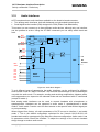
All the key functions for supplying power to the device are handled by the power
management section of the analog controller. This IC provides the following features:
• Stabilizes the supply voltages for the GSM baseband using low drop linear voltage
regulators.
• Switches the module's power voltages for the power-up and -down procedures.
• Delivers, across the VEXT pin, a regulated voltage for an external application. This
voltage is not available in Power-down mode.
• SIM switch to provide SIM power supply.
3.2.1 Minimizing Power Losses
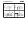
When designing the power supply for your application please pay specific attention to power
losses. Ensure that the input voltage VBATT+ never drops below 3.3V on the AC75 board, not
even in a transmit burst where current consumption can rise to typical peaks of 2A. It should
be noted that AC75 switches off when exceeding these limits. Any voltage drops that may
occur in a transmit burst should not exceed 400mV.
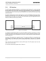
The measurement network monitors outburst and inburst values. The drop is the difference
of both values. The maximum drop (Dmax) since the last start of the module will be saved. In
IDLE and SLEEP mode, the module switches off if the minimum battery voltage (Vbattmin) is
reached.
Example:
VImin = 3.3V
Dmax = 0.4V
Vbattmin = VImin + Dmax
Vbattmin = 3.3V + 0.4V = 3.7V
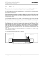
The best approach to reducing voltage drops is to use a board-to-board connection as
recommended, and a low impedance power source. The resistance of the power supply lines
on the host board and of a battery pack should also be considered.
Note:
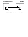
If the application design requires an adapter cable between both board-to-board
connectors, use a flex cable as short as possible in order to minimize power
losses.
AC75_HD_V00.202
Page 24 of 120
27.04.2006