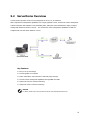
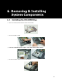
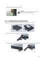
1
Contents 1. Introduction............................................................................................. 2 1.1 System Feature ................................................................................................................................3 1.1.1 Front View............................................................................................................................3 1.1.2 Front Panel Controls and Indicators........................................................................................3 1.1.3 Rear View.............................................................................................................................4 1.1.4 Inner View............................................................................................................................5 1.2 System Specifications .......................................................................................................................6 1.3 Mainboard Layout ............................................................................................................................9 1.3.1 Block Diagram ......................................................................................................................9 1.3.2 Mainboard Layout ............................................................................................................... 10 2. Important Safety ................................................................................... 11 2.1 2.2 2.3 2.4 2.5 2.6 2.7 2.8 2.9 Intended Application Uses .............................................................................................................. 11 Checking the Power Cord................................................................................................................ 11 Earth-Grounded Socket Outlets ....................................................................................................... 12 Before Removing the Access Covers ................................................................................................ 12 Fans .............................................................................................................................................. 12 Electrostatic Discharge (ESD).......................................................................................................... 12 Cooling and Airflow ........................................................................................................................ 13 Battery .......................................................................................................................................... 13 Network Connecting....................................................................................................................... 13 3. System Installation................................................................................ 14 3.1 Preparing for Setup ........................................................................................................................ 14 3.1.1 Unpacking .......................................................................................................................... 14 3.1.2 Packing List ........................................................................................................................ 15 3.1.3 Environmental Specifications ............................................................................................... 16 3.1.4 Installing the Slide Rails into the System ..............................................................................17 3.1.5 Installing the System at the Rack Cabinet............................................................................. 18 3.2 Installing User Serviceable Component ............................................................................................ 19 3.2.1 CPU ................................................................................................................................... 19 3.2.2 Memory.............................................................................................................................. 20 3.2.3 Hard Disk Drive................................................................................................................... 22 3.2.4 PCI Add-on Card ................................................................................................................. 23 4. BIOS and Jumper Setting ...................................................................... 24 4.1 BIOS ............................................................................................................................................. 24 4.1.1 Entering Setup.................................................................................................................... 24 4.1.2 Control Keys ....................................................................................................................... 25 4.1.3 Getting Help ....................................................................................................................... 25 4.1.4 General Help <F1> ............................................................................................................. 26 4.1.5 Menu Bar ........................................................................................................................... 26 4.1.6 Main Menu ......................................................................................................................... 27 4.1.7 Advanced Menu .................................................................................................................. 28 4.1.8 Security Menu..................................................................................................................... 41 4.1.9 Boot Menu.......................................................................................................................... 42 4.1.10 Power Menu ..................................................................................................................... 43 4.1.11 Exit Menu ......................................................................................................................... 45 4.2 Jumper Setting .............................................................................................................................. 46 4.2.1 Clear CMOS Jumper: JBAT1 ................................................................................................. 46 4.2.2 BIOS Recovery Jumper: J10 ................................................................................................ 46 4.2.3 BIOS Write Protect Jumper: J6 ............................................................................................ 46 4.2.4 On-board VGA Enable/Disable Jumper: JVGAD...................................................................... 47 5. Software & Utilities................................................................................ 48 5.1 5.2 NVRAID......................................................................................................................................... 48 5.1.1 Basic Configuration Instruction ............................................................................................ 48 5.1.2 Setting up the BIOS ............................................................................................................ 49 5.1.3 Entering the RAID BIOS Setup Basic Configuration Instruction............................................... 50 5.1.4 NVIDIA RAID Utility Installation ........................................................................................... 54 ServerDome Overview .................................................................................................................... 57 6. Removing & Installing System Components.......................................... 58 6.1 6.2 6.3 6.4 6.5 6.6 6.7 6.8 Installing the CD-ROM Drive ........................................................................................................... 58 Installing the Hard Disk Drive ......................................................................................................... 59 Installing PCI Riser Module ............................................................................................................. 60 Replacing the Power Supply Unit..................................................................................................... 61 Replacing the Cooling Fan Unit........................................................................................................ 62 Installing the Motherboard.............................................................................................................. 63 Installing the CPU Heatsink............................................................................................................. 64 Installing the Front Bezel ................................................................................................................ 64 7. Cable Routing ........................................................................................ 65 7.1 Cable Routing Example................................................................................................................... 65 Preface The information in this User's Guide has been carefully reviewed and is believed to be accurate. The vendor assumes no responsibility for any inaccuracies that may be contained in this document, makes no commitment to update or to keep current the information in this Guide, or to notify any person or organization of the updates. NOTE: For any up-to-date version of this document, please see our web site at www.uniwide.com. UNIWIDE Technologies, Inc. reserves the right to make changes to the product described in this manual at any time and without notice. This product, including software, if any, and documentation may not, in whole or in part, be copied, photocopied, reproduced, translated or reduced to any medium or machine without written consent. Copyright Notice The material in this document is the intellectual property of UNIWIDE Technologies, Inc. We take every care in the preparation of this document, but no guarantee is given as to the correctness of its contents. Our products are under continual improvement and we reserve the right to make changes without notice. Technical Support If a problem arises with your system and no solution can be obtained from the user's manual, please contact your place of purchase or local distributor. Alternatively, please try the following help resources for further guidance. Visit the UNIWIDE website for FAQ, technical guide, BIOS updates, driver updates, and other information: http://www.uniwide.com Contact our technical staff at: [email protected] Revision History Revision Revision History V1.0 Date First release May 2008 1 1. Introduction The key objective for UniServer is to overcome the major challenges faced by developers, and system integrators alike, in deploying ideal server solutions to the market. Although many, key challenges are identified as reliability, performance, value, scalability and manageability. UniServer offers the best in class for each of these challenges by employing the latest technology designed by a specialized sever team. The UniServer 1522LV 1U Rackmount Server is a high-performance barebone system powered by dual AMD® OpteronTM 2000 processors, nVIDIA® nForce Professional 3400 (MCP55V Pro) and Winbond Super I/O chip. In addition, 4 DIMM sockets are supported for CPU. In line with extreme processing and data buffering capability, UniServer is equipped with PCI-Express slot and SATA II with RAID 0, 1 support. For those preferring SATA devices, 2-slot SATA with RAID option is available. Data transfer is optimized with on-board dual PCI-Express Gigabit Ethernet ports. Server management feature is unrivaled by utilizing its dedicated BMC with IPMI 2.0 based ServerDome. A remote management suit handles all aspects of deployment, management and monitoring of UniServer at an individual or aggregate level. Last but not least, UniServer is cable-less and tool-less integration. This well thought out packaging keeps all variations of UniServer ultra cool and easy to maintain, thus, optimizing on reliability and TCO. 2 1.1 System Feature 1.1.1 Front View a. Slim CD-ROM Drive d. Hard Disk Drives b. Front Panel Controls and Indicators e. Rack Mounting Bracket c. Front Bezel 1.1.2 Front Panel Controls and Indicators a. USB 2.0 Ports e. System Fault LED b. Power LED f. c. g. Reset Switch LAN Activity LEDs d. System ID LED System ID Switch h. Power ON/OFF Switch Front Side LEDs LED System Power LAN1/LAN2 Activity System ID System Fault HDD Status HDD Activity Color State Description Blue On System is turned on Power is off Off Off Orange Blink Orange Off No LAN access White On Identification is active by management software or ID LED button Off Off Identification is not active Off Off Running/normal operation Red On Critical or non-recoverable condition Green On HDD exists and is powered Off Off No HDD Green Blink Disk is accessed Off Off No disk activity Network is linked and accessed 3 1.1.3 Rear View a. AC Power Inlet e. VGA Port b. USB 2.0 Ports f. c. g. PCI Slot Serial Port GbE LAN Ports d. PS/2 Port(Keyboard & Mouse) LAN Port Function The LAN port uses a CAT 6 LAN cable for connecting the motherboard to a local area network by means of a network hub. The port has 2 indicator LEDs. LED Link and Activity Speed Color State Green Blink Description LAN is linked and accessed Off Off LAN is not linked Orange On Gigabit mode access Green On 100M mode access Off Off 10M mode access Link and Activity LED Speed LED 4 1.1.4 Inner View a. FAN Modules e. Heatsink b. Power Supply f. PCI-Express Slot c. CPU Air Duct g. Slim CD-ROM d. Memory DIMM Slots 5 1.2 System Specifications Processor Dual socket F (1207pin) Supports up to 2P/8C AMD OpteronTM Processors Dual-Core/Quad-Core AMD OpteronTM 2000 Series processors Integrated 128bit DDR-2 memory controller Chipset NVIDIA® nForceTM Professional 3400 Winbond Super I/O chip Memory 128-bit dual channel memory bus 4 DIMMs for CPU, up to 32GB memory capacity Registered ECC DDR2 400/533/667 SDRAM DIMM SATA Controller Integrated nForceTM Professional 3400 2 ports supporting RAID 0, 1 IDE Controller Integrated nForceTM Professional 3400 One FFC port for CD-ROM Drive Drive Bays Supports 2 hot-swap SATA HDDs Supports Slim CD-ROM Expansion Slots One x16 PCI-Express slot supporting half-length add-on card 6 Rear I/O One VGA port One serial port One PS/2 keyboard & mouse port Two USB 2.0 ports Two RJ45 GbE ports Front LED Panel Two USB 2.0 ports LEDs: Power / GbE LAN1 / GbE LAN2 / ID / System Fault Switches: System ID / Reset / Power System Management FAN connectors For System - Two step speed control BMC Supports IPMI 2.0 specification Auto fan speed control Voltage and fan speed monitoring LAN Controller Integrated in nForce Professional 3400 Support PXE function Video Controller XGI Volari Z7 /16MB BIOS Phoenix BIOS Support ACPI 2.0 with S1/S3 Support AMD Cool’n’Quiet 48-bit LBA support Support USB K/B & Mouse Serial Console Redirection Support USB boot and PXE boot in boot sequence 7 Power Supply 400W single power supply with PFC function AC Input: 100-240V~, 50/60Hz, 8-4A Form Factor 1U (H x W x D): 43.5 x 428 x 436.9 mm (1.7 x 16.85 x 17.2 inch) 8 1.3 Mainboard Layout 1.3.1 Block Diagram 9 1.3.2 Mainboard Layout ① DDR2 Memory DIMM Sockets ② AMD® OpteronTM Socket 1207 - CPU ③ PCI Express x16 Slot ④ CD-ROM Connector ⑤ SATA Connectors ⑥ SATA Connectors ⑦ Fan Connectors ⑧ 24-Pin Power Connector ⑨ 8-Pin CPU Power Connector 10 2. Important Safety Only a technically qualified person shall access, integrate, configure, and service this product. To avoid personal injury or property damage, read, observe, and adhere to all of the following safety instructions and information before you begin installing the product. 2.1 Intended Application Uses This product was evaluated as information technology equipment (ITE), which may be installed in offices, schools, computer rooms, and similar commercial type locations. The suitability of this product for other product categories and environment (such as medical, industrial, alarm systems, and test equipment), other than an ITE application, may require further evaluation. 2.2 Checking the Power Cord CAUTION To avoid electrical shock, check the power cord(s) that will be used with the product: Do not attempt to modify or use the AC power cord(s) if they are not the exact type required. If a power cord is not compatible with the AC wall outlet in your region, get one that meets the following criteria: z The power cord must be properly rated for the AC voltage in your region. z The power cord plug cap must have an electrical current rating that is at least 125% of the electrical current rating of the product. z The power cord plug cap that plugs into the wall socket-outlet must have a grounding type male plug designed for use in your region. z The power cord must have safety certifications for your region, and shall be marked with the certification markings. z The power cord plug cap that plugs into the AC receptacle on the power supply must be an IEC 320, sheet C13, type female connector. z In Europe, the power cord must be less than 4.5 meters (14.76 feet) long, and it must be flexible <HAR> (harmonized) or VDE certified cordage to comply with the chassis' safety certification The power supply cord(s) is the main disconnect device to AC power. The socket outlet(s) shall be near the equipment and shall be readily accessible for disconnection. 11 2.3 Earth-Grounded Socket Outlets CAUTION To avoid electrical shock, the system power cord(s) must be plugged into socket-outlet(s) that is provided with a suitable earth ground. The system will be provided with the following marking: z Connect only to properly earthed socket outlet. 2.4 Before Removing the Access Covers CAUTION To avoid personal injury or property damage, the following safety instructions apply whenever accessing inside the product: z Turn off all peripheral devices connected to this product. z Turn off the system by pressing the power button on the front of the product. z Disconnect the AC power by unplugging all AC power cords from the system or wall outlet. z Disconnect all cables and telecommunication lines that are connected to the system. z Retain all screws or other fasteners when removing access cover(s). product, refasten access cover with original screws or fasteners. z Do not access inside power supply. There are no serviceable parts in the power supply. z Return to manufacturer for servicing. Upon completion of accessing inside the 2.5 Fans CAUTION To avoid injury, do not contact moving fan blades. 2.6 Electrostatic Discharge (ESD) CAUTION Perform the procedures in this product guide only at an electrostatic discharge (ESD) workstation, because the server components can be extremely sensitive to ESD. If no such station is available, you can reduce the risk of electrostatic discharge ESD damage by doing the following. z Wear an antistatic wrist strap and attach it to a metal part of the server. z Touch the metal on the server chassis before touching the server components. 12 z Keep part of your body in contact with the metal server chassis to dissipate the static charge while handling the components. z Avoid moving around unnecessarily. z Hold the server components (especially boards) only by the edges. z Place the server components on a grounded, static-free surface. z Use a conductive foam pad if available but not the component wrapper. z Do not slide the components over any surface. 2.7 Cooling and Airflow CAUTION For proper cooling and airflow, always install all access covers before turning on the system. Operating the system for longer than five minutes without the covers in place can cause overheating and damage to system components. 2.8 Battery CAUTION Risk of explosion if battery is replaced by an incorrect type. Dispose of used batteries according to the instructions. 2.9 Network Connecting CAUTION This equipment is indoor use and all the communication wirings are limited to inside of the building. 13 3. System Installation 3.1 Preparing for Setup 3.1.1 Unpacking ① Main Box ② System Bottom Cushion ③ Heatsink Box ④ UniServer 1522LV Barebone System ⑤ System Top Cushion ⑥ Slide Rail ⑦ Accessory Box CAUTION In setting the product out of the box, hold it in the middle and not the cushion. Depending on the weight of the product, two people together should lift it. 14 3.1.2 Packing List Unpack the package and check if all items listed below are present. If any item contained in the package is damaged or missing, please contact your local dealer for replacement. In addition, keep the box and packing materials for possible future use. 1522LV Barebone Server Slide Rail CPU Heatsink Accessory Box ① Rear Rack Mounting Bracket ② Power Cord (Optional) ③ Manual and Driver CD 15 3.1.3 Environmental Specifications Place In front of the system, minimum 25" of the space is needed for using and managing the system. In rear of the system, minimum 30" of the space is needed for managing the system and airflow. Power supply Before installing the system, check the power capacity of the place where the system is installed. Grounding The system should be grounded. Temperature The system should be installed where the airflow and temperature is proper. If the system is installed in the rack, the temperature in rack should be less than 35 degree Celsius. In most case, the temperature of the rack is higher than that of the out of the rack. Airflow Since the airflow of the system is front-to-rear, please do not cover of the system 16 3.1.4 Installing the Slide Rails into the System This section provides information on installing the system into a rack unit with the slide rails provided. Slide Rail Attach slide rails on both left and right side of the system and secure them with 4 screws. Rear Rack Mounting Brackets As shown in the picture below, align rear rack mounting brackets with the rear frame of the cabinet. And then, secure 2 brackets with 4 screws to the cabinet on both sides. 17 3.1.5 Installing the System at the Rack Cabinet CAUTION Remove all the cables from system before installing. CAUTION System can be heavy. To reduce the risk of personal injury or damage to the equipment, get help to lift and stabilize the system during installation or removal, especially when the system is not fastened to the rails. ① Lift up the system to place 2 slide rails into the position of the rack. ② Suspend system’s slide from the rear rack mounting brackets pre-attached to the cabinet. ③ Secure the system into the cabinet with 4 screws in front. ④ Secure the rear slide of the system on the cabinet with 2 screws. 18 3.2 Installing User Serviceable Component 3.2.1 CPU System mainboard accommodates Socket-F (1207 pin) AMD Opteron TM Processors at 2000 MT (Mega Transfer per second). Follow these instructions to install the CPUs. ① Lift up the socket-locking lever slightly and remove away plastic cover. ② Locate the pin 1 of the CPU socket and pin 1 of the CPU(Marked by a triangular hole in the Pin 1 corner). Put down the locking lever and latch it into the fully locked position. For a dual-processor system, repeat these steps to install CPU into the another socket. Gold Triangle 19 3.2.2 Memory The system mainboard uses Dual Inline Memory Modules (DIMM). The memory DIMMs accommodates Registered ECC (400/533/667) SDRAM DIMM and Double Data Rate Memory (DDR2) memory modules in 128MB, 256MB, 512MB, 1GB, and 2GB, 4GB combinations. Total memory size for CPU is up to 32GB. CAUTION The system mainboard has strict memory type and timing requirements. Before you purchase DDR (Double Data Rate) memory for using in the system mainboard, you should contact your local reseller for a recommend list of system memory that has been validated on this system. It only supports registered memory, not supports unbuffered type memory. CAUTION To take advantage of the 128-bit interface, you must install DIMMs in pairs of two. DIMM0 and DIMM1 are paired; and DIMM2 and DIMM3 are paired. If you are only installing two DIMMs into a Memory Bank, it is recommended that you install them in slots DIMM3 and DIMM4 to get the full bandwidth. NOTICE For optimal dual-channel DDR operation, installing DIMMs in pair is highly recommended. For two DIMMs per CPU, install them far from the CPU. For four or more DIMMs per CPU, install them same method to the CPU. Memory Configuration Chart ( Note: O indicates a populated DIMM Slot, The chart below does not included all the configuration ) Memory Slot # DIMM1 DIMM2 DIMM3 DIMM4 O O O O 128bit memory support O 64bit memory support O O O 20 Memory Installation ① Locate the memory into the socket of the DIMM module ② Make sure the DIMM’s pins are facing down, and check that the pin arrangement on the memory module resembles the one pictured below. ③ Insert the module into the DIMM socket and press down evenly on both ends firmly until the DIMM module is securely in place. (The tabs of the DIMM socket will close-up to hold the DIMM in place when the DIMM is properly installed into the socket.) 21 3.2.3 Hard Disk Drive NOTICE When you install hard disk drive into the system, we recommend using slot #0 first. HDD ID Configuration HDD Type Slot #0 Slot #1 SATA ID 0.0 ID 0.1 22 3.2.4 PCI Add-on Card WARNING Power off power supply completely when adding or removing any expansion card and other system components. Failure to do so may cause severe damage to both your motherboard and expansion card. 3.2.4.1 PCI Add-on Card Installation ① Loosen the screw as shown below. ② Pull the PCI bracket down and remove the blank PCI away. Riser Card Blank PCI ③ Insert the express card into the riser card slot. ④ Pull the PCI bracket up to original position and fasten it to the system. Riser Card Slot Express Card 23 4. BIOS and Jumper Setting 4.1 BIOS This chapter provides information on the BIOS Setup program and allows you to configure the system for optimum use. You may need to run the Setup program when: z An error message appears on the screen during the system booting up, and requests you to run SETUP. z You want to change the default settings for customized features. 4.1.1 Entering Setup Power on the computer and the system will start POST (Power On Self Test) process. When the message below appears on the screen, press <F2> key to enter Setup. Press F2 to enter SETUP If the message disappears before you respond and you still wish to enter Setup, restart the system by turning it OFF and On or pressing the RESET button. You may also restart the system by simultaneously pressing <Ctrl>, <Alt>, and <Delete> keys. NOTICE The items under each BIOS category described in this chapter are under continuous update for better system performance. Therefore, the description may be slightly different from the latest BIOS and should be held for reference only. 24 4.1.2 Control Keys Key Function <F1> or <Alt-H> General Help window <Esc> Exit this menu ←→arrow keys Select a different menu ↑ or ↓ arrow keys Move cursor up and down <Home> or <End> Move cursor to top or bottom of window <PgUp> or <PgDn> Move cursor to next or previous page <F5> or <-> Select the previous value for the field <F6> or <+>or <Space> Select the next value for the field <F9> Load the default configuration values for this menu <F10> Save and exit <Enter> Execute command or enter submenu 4.1.3 Getting Help After entering the Setup menu, the first menu you will see is the Main Menu. Main Menu The main menu lists the setup functions you can make changes to. You can use the arrow keys (↑↓) to select the item. The on-line description of the highlighted setup function is displayed at the bottom of the screen. Sub-Menu If you find a right pointer symbol (▶) appears to the left of certain fields that means a sub-menu can be launched from this field. A sub-menu contains additional options for a field parameter. You can use arrow keys (↑↓) to highlight the field and press <Enter> to call up the sub-menu. Then you can use the control keys to enter values and move from field to field within a sub-menu. If you want to return to the main menu, just press the <Esc >. 25 4.1.4 General Help <F1> The BIOS setup program provides a General Help screen. You can call up this screen from any menu by simply pressing <F1>. item. The Help screen lists the appropriate keys to use and the possible selections for the highlighted Press <Esc> to exit the Help screen. 4.1.5 Menu Bar Once you enter Phoenix TrustedCoreTM Setup Utility, the Main Menu will appear on the screen. On the Main Menu screen, you will see basic BIOS settings including system time & date, and the setup categories the BIOS supplies. Use Arrow keys to move among the items and menus, and make changes to the settings. Main Use this menu for basic system configurations, such as time, date etc. Advanced Use this menu to set up the items of special enhanced features available on your system’s chipset. Security Use this menu to set Supervisor and User Passwords. Boot Use this menu to specify the priority of boot devices. 26 Power Use this menu to specify your settings for power management. Exit This menu allows you to load the BIOS default values or factory default settings into the BIOS and exit the BIOS setup utility with or without changes. 4.1.6 Main Menu The items inside the Main menu are for basic system information and configuration. Each item includes none, one or more setup items. Use the Up/Down arrow keys or <Tab> to highlight the item or field you want to modify and use the <+> or <-> key to switch to the value you prefer. BIOS Date, BIOS Version These items show the information of the system BIOS. (Read-only) QuickBoot Mode Setting the item to [Enabled] allows the system to boot within 5 seconds since it will skip some check items. Summary Screen Select [Enabled] if you want to view the system summary screen. No Pause On BIOS Error Select [Enabled] will allow no pause on BIOS error. 27 System Memory, Extended Memory These items show the memory status of the system. (Read-only) System Time The time format is <HH> <MM> <SS>. System Date The date format is <MM> <DD> <YYYY>. 4.1.7 Advanced Menu Items in the menu are divided into several sub-menus. Each sub-menu provides more settings. To enter the sub-menu, highlight the sub-menu you want to configure and press <Enter>. Installed O/S When multiple operating systems are installed in your system, use this setting to select the major operating system that will be used most commonly. Note that an incorrect setting in this field may cause unexpected errors on the operating systems. NOTICE When installing Linux OS, you must switch this item to [Linux]. 28 Case Open Function The field enables or disables the feature of recording the chassis intrusion status and issuing a warning message if the chassis is once opened. To clear the warning message, set the field to [Reset]. The setting of the field will automatically return to [Enabled] later. CPU Overclock This item specifies the clock frequency of the CPU host bus (FSB) for end users to overclock the processor. BIOS Write Protect This function protects the BIOS from accidental corruption by unauthorized users or computer viruses. When enabled, the BIOS’ data cannot be changed when attempting to update the BIOS with a Flash utility. To successfully update the BIOS, you’ll need to disable this BIOS Write Protect function. You should enable this function at all times. update the BIOS. The only time when you need to disable it is when you want to After updating the BIOS, you should immediately re-enable it to protect it against viruses. Fan Type Control This setting allows you to select the fan type (3-pin or 4-pin) for fan power management. Select 3-pin for UniServer 1522LV system. IOMMU, Size AMD64, one of the 64-bit architectures, contains a device called the IOMMU (Input/Output Memory Management Unit). The IOMMU allows 32-bit devices to see all of the (64-bit addressed) main memory although with a 32-bit address bus you can only address a 32-bit address space. It is an MMU that translates DMA virtual addresses to real physical addresses. Size This setting specifies the memory size for IOMMU. 29 CPU0/CPU1 Information This sub-menu shows the detail processor information. Memory Controller Options This setting is for setting Max Mem Clock and controller options. z Max Mem Clock Use this field to configure the highest clock frequency of the installed DRAM. Users may also assign a lower memory clock frequency here. z DRAM Bank Interleave Interleaved memory is system memory divided into two or more sections. Setting to [Enabled] allows memory to be accessed faster since each section of memory is capable of being utilized at once. 30 z Node Interleave AMD Opteron CPU supports a mode called node interleave. When node interleave is disabled, the memory controller maps the local memory of each processor to a single contiguous range of physical addresses. This allows the operating system to map user data to local memory, whenever possible, to allow programs to access data the most rapidly. When node interleave is enabled, physical addresses are partitioned into 4KB blocks, and alternated among the processors. The operating system is then unable to use NUMA optimizations, and the memory space is treated as if the system were an SMP system. z SW Mem Hole Remap This setting enables the software to remap the physical memory to an address higher than 4GB. z ACPI SRAT Table The Static Resource Affinity Table (SRAT) can be used to describe the physical location of processors and memory in large-scale systems (such as CC-NUMA) to the Microsoft Windows Server 2003 operating system, allowing threads and memory to be grouped in an optimal manner. z Memory Unganged Mode The unganged mode can split the available bandwidth into two distinct channels and is supported by AMD HyperTransport technology. ECC Options z ECC Mode This setting specifies the level of ECC protection. If [User] is selected, individual ECC options may be changed. Other options except [Disabled] serve as presets. For [Super] mode, all memory is scrubbed every 8 hours. 31 z ECC Error Checking This setting enables/disables ECC (Error Correction Code) checking, a method of checking the integrity of data in DRAM. ECC provides more elaborate error detection than parity; ECC can detect multiple-bit errors and can locate and correct single-bit errors. z ECC Error Log This setting logs the ECC error. z Chipkill Chipkill is a new Advanced ECC (Error Correction Code) memory technology that protects servers from system downtime caused by memory failures. z ECC Scrub Redirection This setting enables/disables ECC Scrubber to correct errors detected in DRAM during normal CPU requests (foreground scrubbing). z DRAM ECC Scrub Control The DRAM ECC Scrub option controls the frequency at which memory read options are corrected while the system is in an idle state. z DCache ECC Scrub Control The Data Cache ECC Scrub option controls the time allotted for the L1 memory cache to be corrected when in an idle state. z L2 ECC Scrub Control The L2 ECC Scrub option controls the time allotted for the L2 memory cache to be corrected when in an idle state. Integrated Devices 32 z USB Control This setting enables/disables the onboard USB host controller. z USB BIOS Legacy Support Set to [Enabled] if your need to use any USB 1.1/2.0 device in the operating system that does not support or have any USB 1.1/2.0 driver installed, such as DOS and SCO Unix. z MAC LAN, MAC 1 LAN These settings allow you to enable/disable the specified device controllers. z SATA0 Controller, SATA1 Controller, SATA2 Controller These settings allow you to enable/disable the on-chip Serial-ATA controllers. z Interrupt Mode This BIOS feature is used to enable or disable the motherboard's APIC (Advanced Programmable Interrupt Controller). The APIC provides multiprocessor support, more IRQs and faster interrupt handling. However, it is only supported by newer operating systems like Microsoft Windows NT, Windows 2000 and Windows XP. Older operating systems like DOS or Windows 95/98 do not support this feature. It is recommended that you select APIC if you are using a newer operating system like Windows XP. Select PIC only if you are using an older operating system like DOS or Windows 95/98. NV RAID Configuration z NV RAID Configuration This setting enables/disables the nVIDIA software RAID configuration. note that the SATA controller must be enabled for RAID feature to function. z Master SATA0/1/2 Primary, Master SATA0/1/2 Secondary These settings show up only when the NV RAID Configuration is set to [Enabled]. Note that enabling Master SATA Secondary requires enabling Secondary SATA Channel. 33 IDE Configuration z Large Disk Access Mode Defaulting this setting to [DOS] will create a Translated FDPT. Compatible ill-behaved applications will operate correctly when [DOS] is selected. Setting to [Other] will create a Standard FDPT. Incompatible ill-behaved applications will function correctly with [Other]. z Local Bus IDE Adapter This setting controls the onboard IDE adapter. 34 z Primary Master, Primary Slave [Type] Press PgUp/<+> or PgDn/<-> to select [Manual], [None] or [Auto] type. Note that the specifications of your drive must match with the drive table. The hard disk will not work properly if you enter improper information for this category. If your hard disk drive type is not matched or listed, you can use [Manual] to define your own drive type manually. [Multi-Sector Transfers] Any selection except Disabled determines the number of sectors transferred per block [LBA Mode Control] Enabling LBA causes Logical Block Addressing to be used in place of Cylinders, Heads and Sectors [32-Bit I/O] Enables 32-bit communication between CPU and IDE card [Transfer Mode] Selects the method for transferring the data between the hard disk and system memory [Ultra DMA Mode] Indicates the type of Ultra DMA Floppy Configuration z Legacy Diskette A This setting allows you to set the type of floppy drives installed. z Floppy Check This setting causes the BIOS to search for floppy disk drives at boot time. activate the floppy disk drives during the boot process. When enabled, the BIOS will 35 I/O Device Configuration z KBC Clock This BIOS feature allows you to adjust the keyboard interface clock for a better response or to fix a keyboard problem. It is recommended that you select a higher clock speed for a better keyboard response. But if the keyboard performs erratically or fails to initialize, try a lower clock speed. z Serial Port A/B These settings enable/disable the onboard Serial Port A / B. z Base I/O Address These settings specify the base I/O port addresses of the onboard Serial Port A / B. z Interrupt These settings specify IRQs for the Serial Port A / B. z Floppy Disk Controller This setting enables/disables the onboard floppy disk controller. z Base I/O Address This setting specifies the base I/O port address of the onboard floppy drive. 36 IPMI z IPMI Specification Version Indicate the IPMI (Intelligent Platform Management Interface) version. z BMC Hardware/Firmware Version Indicate the BMC (Baseboard Management Controller) version. z System Event Logging This function is used to log system events. z Clear System Event Log This function is used to clear system event logs. z Existing Event Log Number Indicates how many event logs are existing. z Remaining Event Log Number Indicates how many event logs are remaining. z Event Log Control / SYS Firmware Progress These fields allow you to log System Firmware Progress. z BIOS POST Watchdog Setting the option to [Enabled] If BIOS POST fails, Watchdog restarts the BIOS POST. 37 z System Event Log This setting shows the real-time system event logs on the system monitor sensor. z Dynamic or Static IP Config This setting is used to configure your dynamic (temporary) or static (permanent) network IP. Setting to [DHCP] (Dynamic Host Configuration Protocol) allows the network IP to be automatically assigned. IP Address, IP Subnet Mask, Default Gateway (Optional) Use these settings to set up the IP address, IP subnet mask, and default gateway for your system network. These settings appear only when the Dynamic or Static IP Config is set to [Static IP] or [No Change]. 38 Console Redirection z Com Port Address This setting enables/disables the Com port address for console connection. z Baud Rate This setting specifies the transfer rate (bits per second) of Console Redirection. z Console Type This setting specifies the console type. z Flow Control This feature allows you to enable flow control. z Console Connection This feature indicates whether the console is connected directly to the system or a modem is used for connection. z Continue C. R. after POST Selecting [On] will enable Console Redirection after OS has loaded. 39 DMI Event Logging z Event Log Capacity/Validity These items indicate the status of Event log validity and capacity. z View DMI Event Log Press [Enter] to view the contents of the DMI event log. z Clear All DMI Event Logs When this setting is set to [Yes], the DMI event log will be cleared at next POST stage. will automatically set this option to [No]. z Then, the BIOS Event Logging This setting disables/enables the BIOS to log DMI (Desktop Management Interface) events. z Mark DMI Events as Read Press [Enter] and a screen pops up, asking users to confirm whether or not to clear all DMI event logs immediately. Press [Y] and [Enter], the BIOS will clear all DMI event logs right away. 40 4.1.8 Security Menu This section lets you set security passwords to control access to the system at boot time and/or when entering the BIOS setup program. It also allows you to set virus protection at hard disk boot sector. Supervisor Password Is/ User Password Is It shows the preset supervisor/user password. (read only) Set Supervisor Password/ Set User Password Enabling Supervisor Password requires a password for entering Setup. The passwords are not case sensitive. Pressing <Enter> at either Set Supervisor Password or Set User Password displays the following message: Set Supervisor Password Enter New Password: Confirm New Password: [ [ ] ] Type the password and press <Enter>. Repeat. Password on Boot Choosing [Enabled] requires a password on boot. It requires prior setting of the supervisor password. If the supervisor password is set and this option is disabled, BIOS assumes the user is booting. 41 4.1.9 Boot Menu Use this menu to arrange and specify the priority of the devices from which the BIOS will attempt to boot the Operating System. Boot Priority Order This setting allows users to set the boot priority of the specified devices. Refer to the Item Specific Help on the right pane for instructions. Excluded from Boot Order This setting allows users to exclude the specified devices from the Boot Order list. 42 4.1.10 Power Menu Use this menu to specify your settings for Power Management. Remember that the options available depend upon the hardware installed in your system. Enable Cool’n’Quiet This feature is especially designed for AMD Athlon processor, which provides a CPU temperature detecting function to prevent your CPU from overheading due to heavy workload. Spread Spectrum When the motherboard’s clock generator pulses, the extreme values (spikes) of the pulses creates EMI (Electromagnetic Interference). The Spread Spectrum function reduces the EMI generated by modulating the pulses so that the spikes of the pulses are reduced to flatter curves. Enable Multimedia Timer This setting enables the Multimedia Timer to achieve better resolution for multimedia and other time-sensitive applications. Power Loss Control This setting specifies whether your system will reboot after a power failure or interrupt occurs. Available settings are: [Stay Off] Returns the system to an off state. [Power On] Returns the system to an on state. [Last State] Restores the system to the previous status before power failure or interrupt occurred. 43 ACPI Suspend Support This item specifies the power saving modes for ACPI function. If your operating system supports ACPI, you can choose to enter the Standby mode in S1 (POS) or S3 (STR) fashion through the setting of this field. Wake Up by LAN Select [Enabled] to wake up the system when incoming signals are detected on the specified LAN devices. Wake Up by Ring An input signal on the serial Ring Indicator (RI) line (in other words, an incoming call on the modem) awakens the system from a soft off state. Resume On Time Select [On] to wake up the system at predetermined time. Resume Time The time format is <HH> <MM> <SS>. Resume Date The date format is <MM> <DD> <YYYY>. 44 4.1.11 Exit Menu The following sections describe each of the options on this menu. Note that <Esc> does not exit this menu. You must select one of the items from the menu or menu bar to exit. Exit Saving Changes When you want to quit the Setup menu, you can select this option to save the changes and quit. Exit Discarding Changes When you want to quit the Setup menu, you can select this option to abandon the changes. Load Setup Defaults The option allows users to restore all of the BIOS settings to the Optimal Defaults. The Setup Defaults are the default values set by the mainboard manufacturer specifically for the optimized performance of the mainboard. Discard Changes The option allows users to restore all of the BIOS settings to previous values. Save Changes The option allows users to save the changes without exiting Setup. options on this menu. Note that <Esc> does not exit this menu. The following sections describe each of the You must select one of the items from the menu or menu bar to exit. 45 4.2 Jumper Setting 4.2.1 Clear CMOS Jumper: JBAT1 There is a CMOS RAM onboard that has a power supply from external battery to keep the data of system configuration. With the CMOS RAM, the system can automatically boot OS every time it is turned on. If you want to clear the system configuration, set this jumper to clear data. NOTICE You can clear CMOS by shorting 2-3 pin while the system is off. Then return to 1-2 pin position. Avoid clearing the CMOS while the system is on; it will damage the mainboard. 4.2.2 BIOS Recovery Jumper: J10 Users can short connect pin#2-3 to recover the system BIOS. When the system is done with the job, the buzzer will beep to remind users to set the jumper to its normal state (pin#1-2 short connected). 4.2.3 BIOS Write Protect Jumper: J6 This jumper is used to enable/disable the BIOS flash. When you intend to update the BIOS code, short connect pin#1-2 of this jumper first. Under normal operation, we suggest that you enable the BIOS write protect by short connecting pin#2-3 of this jumper to protect the system BIOS from virus infection. 46 4.2.4 On-board VGA Enable/Disable Jumper: JVGAD This jumper is used to enable/disable the on-board VGA. When you want to use on-board VGA, short connect pin#1-2 of this jumper (Default option). If you want to use add-on VGA card and disable on-board VGA, short connecting pin#2-3 of this jumper. 47 5. Software & Utilities 5.1 NVRAID 5.1.1 Basic Configuration Instruction The following are the basic steps for configuring NVRAID 5.1.1.1 Non-Bootable RAID Array ① Choose the hard disks that are to be RAID enabled in the system BIOS. ② Specify the RAID level, either Mirroring (RAID 1), Striping (RAID 0), Striping and Mirroring (RAID 0+1), or Spanning (JBOD) and create the desired RAID array. ③ Install the operating system on one hard disk, then reboot the system. ④ Run the Windows nForce Setup application and install the RAID driver. ⑤ Initialize the NVRAID Array. 5.1.1.2 Bootable RAID Array ① Choose the hard disks that are to be RAID enabled in the system BIOS. ② Specify the RAID level, either Mirroring (RAID 1), Striping (RAID 0), Striping and Mirroring (RAID 0+1), or Spanning (JBOD) and create the desired RAID array. ③ Boot from the Windows CD, then press F6 when the Windows Setup appears. ④ Insert the RAID driver floppy to install the nForce RAID diver. ⑤ Initialize the NVRAID Array. 48 5.1.2 Setting up the BIOS Be sure to enable the “nVIDIA RAID Function in nVIDIA RAID Setup of Integrated Peripherals” in BIOS before configuring the NVRAID BIOS. After that press F10 to save the configuration and exit. reboot right away. The server will Then enter the RAID BIOS setup by pressing F10 when prompted, and follow the procedures described below to setup up the NVRAID BIOS. NVRAID BIOS setup lets you choose the RAID array type and which hard drives you want to make part of the array. ① Start your computer, then press “F2” to enter the BIOS setup. Devices, then, press Enter. Use the arrow keys to select Integrated ② Use the arrow keys to select the NV RAID Configuration (see the picture), then press Enter. ③ From the NV RAID Configuration window, "enable" the RAID Enable, the other items would be light, then you can enable the disk that you want to use as RAID disks. ④ Press F10 to save the configuration and exit. 49 5.1.3 Entering the RAID BIOS Setup Basic Configuration Instruction ① After rebooting your system, wait until you see the RAID software prompting you to press F10. prompt appears as part of the system POST and boot process prior to loading the OS. The RAID ② Press <N>, and the NVIDIA RAID Utility-Define a New Array window will appears(See the picture). default RAID Mode is set to Mirroring and Striping Block is set to Optimal. The 5.1.3.1 Understanding the Define a New Array Window Use the Define a New Array window to Select the RAID Mode Set up the Striping Block Specify which disks to use for the RAID Array Depending on the platform used, the system can have one or more channels. In a typical system there is usually one controller and multiple channels, and each channel has a slave and a master. The channel/controller/master/slave status of each hard disk is given in the Loc(location) columns of the Free Disks and Array Disks lists. 1.0.M M: Master S: Slave 0: Channel Adapter - adapter 0 is used for PATA drives 1 and above is used for SATA drives. 50 In upper picture 1.0.M means the hard drive is attached to Adapter 1, Channel 0, and the drive is set to Master. The following is a list of all possible combinations: Serial ATA 1.0.M Adapter 1, Channel 0, Master 1.1.M Adapter 1, Channel 1, Master 1.2.M Adapter 1, Channel 2, Master 1.3.M Adapter 1, Channel 3, Master 2.1.M Adapter 2, Channel 1, Master 2.2.M Adapter 2, Channel 2, Master NOTICE There is no such thing as Slave drive in Serial ATA. All drives are considered to be Master since there is a one to one connection between the drive and the controller. 5.1.3.2 Using the Define a New Array Window If necessary, press the tab key to move from field to field until the appropriate field is highlighted. Selecting the RAID Mode By default, this is set to mirroring. To change to a different RAID mode, press the down arrow key until the mode that you want appears in the RAID mode box-either mirroring, striping, spanning, or stripe mirroring. Selecting the Striping Block Size Striping block size is given in kilobytes, and affects how data is arranged on the disk. It is recommended to leave this value at the default Optimal, which is 32KB, but the values can be between 4 KB and 128 KB. Assigning the Disks The disks that you enabled from the RAID Config BIOS setup page appear in the Free Disks block. the drives that are available for use as RAID array disks. To designate a free disk to be used as a RAID array disk, These are ① Tab to the Free Disks section. The first disk in the list is selected ② Move it from the Free Disks block to the Array Disks block by pressing the right arrow key(→). The first disk in the list is moved, and the next disk in the list is selected and ready to be moved. ③ Continue pressing the right-arrow key (→) until all the disks that you want to use as RAID array disks appear in the Array Disks block. The below picture illustrates the Define a New Array window after two disks have been assigned as RAID1 array disks. 51 NVIDIA RAID Utility – Array Disks 5.1.3.3 Completing the RAID BIOS Setup ① After assigning your RAID array disks, press F7. The Clear disk data prompt appears. ② Press Y to clear all drive data. The Array List screen appears, where you can review the RAID arrays that you have set up. 52 ③ Use the arrow keys to select the array that you want to set up, and then press Enter. The Array Detail screen appears. The Array Detail screen shows information about the array that you selected, such as Striping Block used, RAID Mode, Striping Width, Disk Model Name, and disk capacity. ④ If you want to mark this disk as empty and wipe out all its contents then press C. ⑤ At the prompt, press Y to wipe out all the data, otherwise press N. ⑥ Press Enter again to go back to the previous window and then press F10 to exit the RAID setup. 53 5.1.4 NVIDIA RAID Utility Installation 5.1.4.1 Installing the NVIDIA RAID Driver Under Windows (For Non-bootable RAID Array) This section describes how to setup the application and install the RAID software which will upgrade the Windows IDE driver and install the RAID driver. ① Start the nForce Setup program to open the NVIDIA Windows nForce Drivers page. ② Select the modules that you want to install. Select the relative options that you have configured. ③ Click Next and then follow the instructions. ④ After the installation is completed, be sure to reboot the system. ⑤ After the reboot. Initialize the newly created array. 54 5.1.4.2 Installing the RAID Driver (For bootable RAID Array) ① After you complete the RAID BIOS setup, boot from the Windows CD, and the Windows Setup program starts. ② Press F6 and wait for the Windows Setup screen to appear. ③ Specify the NVIDIA drivers: ⓐ Insert the floppy that has the RAID driver, press S, then press Enter. The Windows Setup screen appears as below: ⓑ Select "NVIDIA RAID CLASS DIRVER" and then press Enter ⓒ Press S again at the Specify Devices screen, then press Enter. ⓓ Select " NVIDIA nForce Storage Controller" and then press Enter. The following Windows Setup screen appears listing both drivers: 55 ④ Press Enter to continue with operating system Installation, Be sure to copy the files from the floppy is complete, then take out the floppy. ⑤ Following the instructions on how to install operating system, During the GUI portion of the installation you might be prompted to click Yes to install the RAID driver. Click Yes as many times as needed in order to finish the installation. ⑥ This will not be an issue with a signed driver. NOTICE Each time you add a new hard drive to a RAID array, the RAID driver will have to be installed under Windows once for that hard drive. After that, the driver will not have to be installed. 56 5.2 ServerDome Overview The ServerDome provides remote server management for the 1U, 2U, 3U UniServer. With comprehensive management capabilities from a single graphical console, ServerDome remote management software automates and simplifies IT and networking tasks, letting the system administrator deploy, configure, manage and maintain X number of servers. The ServerDome remote management capabilities are IPMI 2.0 compliant and work with either Windows or Linux. Key Features z Easy to set up and manage z Provides graphic user interface z Failure notifications with customized e-mail and popup message. z Provides remote management capabilities through SNMP and IPMI. z System HW resource real-time monitoring z System OS resource real-time monitoring NOTICE For details, please refer to the ServerDome manual which included ServerDome CD. 57 6. Removing & Installing System Components 6.1 Installing the CD-ROM Drive ① Screw two brackets and the interface board to the CD-ROM. ② Remove the blank CD-ROM. ③ Locate the CD-ROM kit right into the place on the chassis and then slide it forward. ④ Push the lock tension down to secure the CD-ROM kit. 58 ⑤ Install the FFC(Flexible Flat Cable) of CD-ROM drive. CAUTION Face the conduct side down and lock the connector to secure the cable. Do not treat the connector by force. 6.2 Installing the Hard Disk Drive ① Remove the blank disk from the disk carrier and secure HDD to the carrier with four screws. ② Insert the disk carrier into the bay and then close the handle to lock. ③ In removing the HDD carrier, push the release button of the carrier and gently pull the drive carrier outward. 59 6.3 Installing PCI Riser Module ① Loosen the screw of the PCI lock bracket. PCI lock bracket ② Pull the PCI bracket to the right and backward. PCI bracket ③ Insert the express card into the riser card slot of the chassis. ④ Lift PCI lock bracket up and secure the screw. 60 6.4 Replacing the Power Supply Unit CAUTION In removing the power supply, handle the heavy unit with care ① Remove away 3 mounting screws from rear and bottom side of the chassis. ② Pull out the both 24-pin and 8-pin CPU power cable from the system. ③ Take the PSU out of the system carefully. 61 6.5 Replacing the Cooling Fan Unit WARNING Do not remove the fan module while operating the system. In installing the fan module, carefully set the unit on the fan connector. ① Take out the cable duct and cut the cable tie for the cable alignment. ② Pull out both fan cable connectors from the main board. ③ Pull out fan A with carefully treating the cable. A B A B ④ Pull out fan B with carefully treating the cable also. *To install new fans, follow the same process in reverse way. 62 6.6 Installing the Motherboard CAUTION In order to remove or install the motherboard, remove the power module, AC strip unit, PCI riser card unit, HDD Carrier, HDD LED Boards and Cooling FAN unit beforehand. ① Remove the power supply unit and HDD carriers away from the system beforehand. ② Place the motherboard on the chassis standoffs so that each of the nine mounting holes fit into the standoff. CAUTION Check the insulator of motherboard on the chassis and then insert the front side of motherboard into the chassis first. ③ Secure the motherboard on the chassis with the screws. 63 6.7 Installing the CPU Heatsink CAUTION Make sure that thermal interface material should be pasted on the bottom side of the heatsink. 6.8 Installing the Front Bezel ① Locate the front bezel on the chassis as shown below. ② Slide the bezel toward the left until it makes the click sound. ③ In removing the bezel, pull up the lever of the rear side bezel and slide the bezel to the right 64 7. Cable Routing 7.1 Cable Routing Example UniServer 1522LV system has 4 cables for CPU Power, USB, front LED board and CD-ROM. This is the example of cable routing. a. Power Cables b. Front LED Cable c. FFC CD-ROM Cable d. USB Cable 65