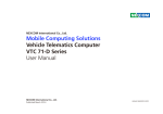
1
UNO-2050
GX1-300 Universal Network Controller
with 2 x LAN, 2 x RS-232, 2 x isolated
RS-232/422/485, 16 x isolated DI/O
User’s Manual
Copyright notice
This document is copyrighted, 2007, by Advantech Co., Ltd. All rights
are reserved. The original manufacturer reserves the right to make
improvements to the products described in this manual at any time
without notice.
No part of this manual may be reproduced, copied, translated or
transmitted in any form or by any means without the prior written
permission of the original manufacturer. Information provided in this
manual is intended to be accurate and reliable. However, the original
manufacturer assumes no responsibility for its use, nor for any
infringements upon the rights of third parties which may result from
such use.
Acknowledgements
IBM, PC/AT, PS/2 and VGA are trademarks of International Business
Machines Corporation.
Intel® and Pentium® are trademarks of Intel Corporation.
Microsoft Windows and MS-DOS are registered trademarks of
Microsoft Corp.
C&T is a trademark of Chips and Technologies, Inc.
All other product names or trademarks are properties of their respective owners.
Part No. 2003205001
Printed in Taiwan
2nd Edition
Sep. 2007
Product warranty
Advantech warrants to you, the original purchaser, that each of its
products will be free from defects in materials and workmanship for
one year from the date of purchase.
This warranty does not apply to any products that have been repaired
or altered by persons other than repair personnel authorized by
Advantech, or which have been subject to misuse, abuse, accident or
improper installation. Advantech assumes no liability under the terms
of this warranty as a consequence of such events.
Because of Advantech high quality-control standards and rigorous
testing, most of our customers never need to use our repair service. If
an Advantech product is defective, it will be repaired or replaced at no
charge during the warranty period. For out-of-warranty repairs, you
will be billed according to the cost of replacement materials, service
time and freight. Please consult your dealer for more details. If you
think you have a defective product, follow these steps:
1. Collect all the information about the problem encountered. (For
example, CPU speed, Advantech products used, other hardware and
software used, etc.) Note anything abnormal and list any on-screen
messages you get when the problem occurs.
2. Call your dealer and describe the problem. Please have your manual,
product, and any helpful information readily available.
3. If your product is diagnosed as defective, obtain an RMA (return
merchandize authorization) number from your dealer. This allows us
to process your return more quickly.
4. Carefully pack the defective product, a fully completed Repair and
Replacement Order Card and a photocopy proof of purchase date
(such as your sales receipt) in a shippable container. A product
returned without proof of the purchase date is not eligible for
warranty service.
5. Write the RMA number visibly on the outside of the package and
ship it prepaid to your dealer.
Technical support and sales assistance
If you have any technical questions about the UNO-2050 or any other
Advantech products, please visit our support website at:
http://www.advantech.com/support
For more information about Advantech’s products and sales information, please visit:
http://www.advantech.com
Contents
Chaper 1
1.1
1.2
1.3
1.4
1.5
Introduction ....................................................................... 2
Hardware Specifications .................................................. 3
Safety Precautions ............................................................ 6
UNO-2050 Series ............................................................. 7
Chassis Dimensions ......................................................... 8
Chaper 2
2.1
2.2
2.3
2.4
2.5
2.6
2.7
2.8
2.9
2.10
2.11
2.12
2.13
Hardware Functionality ............................. 9
UNO-2050 Peripherals .................................................. 10
COM1 ~ COM2: RS-232 Interfaces........................... 10
COM3 ~ COM4:
Isolated 5-wire RS-232/422/485 Interfaces ............... 11
On-board Isolated Digital Input ................................... 12
On-board Isolated Digital Output ................................ 16
On-board Isolated Counter/Timer .............................. 18
LAN: Ethernet Connector ............................................ 24
Power Connector ............................................................ 24
LED Indicators ............................................................... 24
PS/2 Keyboard and Mouse Connector ....................... 24
VGA: VGA Display Connector ..................................... 25
Programmable LED and Buzzer for
System Diagnosis ........................................................... 25
RESET: Reset Button ................................................... 26
Chaper 3
3.1
3.2
3.3
Overview ..................................................... 1
Initial Setup ............................................... 27
Insert CompactFlash Card ........................................... 28
Chassis Grounding ......................................................... 28
Connect the Power ......................................................... 29
3.4
3.5
3.6
Plug-in Screw Terminal Block Field
Wiring Considerations................................................... 29
BIOS Setup and System Assignments ........................ 30
HDD Extension Flexibility .......................................... 30
Appendix A Pin Assignments ................................... 31
A.1
A.2
A.3
Board Connector and Jumpers .................................... 32
Standard RS-232 Serial Port (COM1 ~ C0M2) ......... 34
Isolated 5-wire RS-232/422/485 Serial Port
(COM3 ~ COM4) .......................................................... 35
A.4 Ethernet RJ-45 Connector (LAN1~LAN2) ............... 38
A.5 Phoenix Power Connector (CN3) ................................ 39
A.6 PS/2 Keyboard and Mouse Connector (KM1) .......... 39
A.7 VGA Display Connector (VGA1) ................................. 40
A.8 CompactFlashTM Master/Slave Jumper Setting
(JP2) ................................................................................. 41
A.9 Enhanced IDE connctor (CN2) .................................... 42
A.10 LCD connector (CN7, Reserved) ............................... 43
A.11 UNO-2050 Control Register ........................................ 45
Figures
Figure 1-1:
Chassis dimensions ................................................................ 8
Figure
Figure
Figure
Figure
Figure
Figure
Figure
Figure
Figure
2-1:
2-2:
2-3:
2-4:
2-5:
2-6:
2-7:
2-8:
2-9:
UNO-2050 front panel ............................................................ 10
UNO-2050 rear panel ............................................................. 10
Digital input connector pin assignments ............................... 12
Isolated digital input connection ............................................. 13
Digital output connector pin assignments ............................. 16
Isolated digital output connection .......................................... 17
Counter 0 function block ......................................................... 19
Counter 1 function block ......................................................... 20
32-bit Counter function block .................................................. 20
Figure 3-1:
Chassis Grounding connection ............................................. 28
Figure A-1:
Figure A-2:
Figure A-3:
UNO-2050 connector and jumper locations (Top View) ........ 32
UNO-2050 connector and jumper locations (Bottom View) .. 32
RS-485 Wiring topology .......................................................... 38
Tables
Table
Table
Table
Table
Table
Table
Table
Table
Table
Table
Table
Table
Table
Table
Table
Table
Table
Table
2-1:
2-2:
2-3:
2-4:
2-5:
2-6:
2-7:
2-8:
2-9:
2-10
2-11
2-12
2-13
2-14:
2-15:
2-16:
2-17:
2-18:
Table A-1:
Table A-2:
Table A-3
Table A-4:
Table A-5:
Table A-6:
Table A-7:
Table A-8:
Table A-9:
Table A-10:
Table A-11:
Table A-12:
Table A-13:
Serial ports default setting ...................................................... 11
Digital input connector signal description .............................. 12
Interrupt control register bit map ............................................ 14
Interrupt disable/enable control bit values ............................. 15
Interrupt triggering edge control bit values ............................. 15
Interrupt flag bit values ............................................................ 15
Digital output connector signal description ........................... 16
JP12 Digital output power on configuration ........................... 17
Counter/Timer control register bit map .................................. 18
Counter clock source control bit ............................................. 21
Counter internal clock control bit ............................................ 21
Counter gate source control bit .............................................. 22
Counter output destination ..................................................... 22
Counter interrupt flag control bit ............................................. 23
32-bit counter control bit ......................................................... 23
LED and Buzzer control register bit map ................................ 25
Programmable LED control bit ............................................... 26
Programmable Buzzer control bit ........................................... 26
UNO-2050 connectors and jumpers ...................................... 33
RS-232 serial port pin assignments ...................................... 34
Isolated 5-wire RS-232/422/485 serial port
pin assignments ..................................................................... 35
Jumpers to select 5-wire RS-232/422/485 ............................ 35
RS-485 auto flow control mode and RS-422 master/slave
mode selection ....................................................................... 36
JP7 RS-422/485 terminal resistor setting .............................. 37
Ethernet RJ-45 connector pin assignments .......................... 38
Phoenix power connector pin assignments .......................... 39
Keyboard and Mouse connector pin assignments ................ 39
VGA adaptor cable pin assignments ..................................... 40
IDE hard drive connector ........................................................ 42
LCD connector ........................................................................ 43
UNO-2050 control register ..................................................... 45
CHAPTER
1
UNO-2050
Overview
This chapter gives background information on the UNO-2050. It shows you the
UNO-2050 overview and specifications.
Sections include:
• Introduction
• Hardware Specifications
• Safety Precautions
• UNO-2050 Series
• Chassis Dimension
1.1 Introduction
Are you looking forward to a suitable embedded Application Ready
Platform (ARP) that could shorten your development time and offer
rich networking interfaces to fulfill your extensive needs in different
kind of projects? Advantech Universal Network Controller (UNO-2000
series) is your ANSWER concentrating the services on Networkenabled Application Ready Platform total solution.
Leveraging field-approved and worldwide-awareness real-time OS
technology, Advantech UNO-2000 series provides Windows CE .NET
ready solution and support several standard networking interfaces,
such as Ethernet, Wireless LAN, RS-232/422/485 and so on. Because
of its openness, great expansion capability and reliable design –
fanless and diskless, Advantech UNO-2000 series becomes an ideal
embedded platform to implement custom applications in diversified
applications.
2
UNO-2050 User's Manual
1.2 Hardware Specifications
CPU: NS Geode GX1-300 MHz
Chipset: NS CS5530A
BIOS: AWARD 256 KB FLASH BIOS
RAM: 64/128 MB SDRAM on board
VGA: Supports VGA and VESA
- Display memory: 1 ~ 4 MB share memory, set in BIOS
- CRT display mode: Non-interlaced CRT monitors resolutions up to
1280 x 1024 @ 256 colors or 1024 x 768 @ 16 bpp
- DB-15 VGA connector
Serial Port: Two standard RS-232 ports
- Data bits: 5, 6, 7, 8
- Stop bits: 1, 1.5, 2
- Parity: none, even, odd
- Speed: 50 ~ 115.2 Kbps
- Data signals: TxD, RxD, RTS, CTS, DTR, DSR, DCD, RI, GND
- Max data distance: 50 feet (15.2 meters)
Serial port: 2 x 5-wire RS-232/422/485
- Automatic RS-485 data flow control
- 2000 VDC surge protection and 1500 VDC isolation
- Stop bits: 1, 1.5, 2
- Parity: non, even, odd
- RS-232 Speed: 50 ~ 230.4 Kbps
- RS-422/485 speed: 50 ~ 921.6 Kbps
- 5-wire RS-232 data signals: TxD, RxD, RTS, CTS, GND
- RS-422 data signals: TxD+, TxD-, RxD+, RxD-, GND
Chapter 1 UNO-2050 Overview
3
- RS-485 data signals: DATA+, DATA-, GND
- RS-232 max data distance: 50 feet (15.2 meters)
- RS-422/485 max data distance: 4000 feet (1200 meters)
- Plug-in screw-terminal block: Accepts 0.5 mm2 to 2.5 mm2 , 1 - #12 or
2 - #14 to #22 AWG
Ethernet Port: Dual 10/100Base-T Ethernet
- LAN chip: Realtek 8139C chipset supports
- LED on the front side
8-ch isolated digital input: (DI0~DI7)
- 2,000 VDC isolation, 2000 VDC ESD protection and 70 VDC over-voltage
protection
- 0 ~ 50 VDC input range and 10 KHz speed
- Input Voltage
- Logic 0: 0 ~ 3 VDC
- Logic 1: 10 ~ 50 VDC
- Input Current
- 10 VDC: 1.7 mA (typical)
- 12 VDC: 2.1 mA (typical)
- 24 VDC: 4.4 mA (typical)
- 48 VDC: 9.0 mA (typical)
- 50 VDC: 9.4 mA (typical)
- Interrupt handling capability
- Plug-in screw-terminal block: Accepts 0.5 mm2 to 2.5 mm2 , 1 - #12 or
2 - #14 to #22 AWG
8-ch isolated digital output: (DO0 ~ DO7)
- 2,000 VDC isolation and 200 mA max / channel sink current
- Keep output status after system hot reset
- 5 ~ 40 VDC output range and 10 KHz speed
- Plug-in screw-terminal block: Accepts 0.5 mm2 to 2.5 mm2 , 1 - #12 or
2 - #14 to #22 AWG
4
UNO-2050 User's Manual
Two 16-bit counters/timers:
- Counter source: DI6 & DI7, Pulse output: DO6 & DO7
- Can be cascaded as one 32-bit counter/timer
- Down counting, Preset counting value
- Interrupt handling, speed: 40 KHz
- Timer time base: 100 KHz, 10 KHz, 1 KHz, 100 Hz
SSD: One Type I / Type II CompactFlashTM card slot inside the chassis
HDD: Offer HDD extension kit for installation of one standard 2.5"
HDD.
LED: One power LED, one IDE LED, one programmable LED and one
programmable buzzer
Keyboard/Mouse connector: Mini-DIN connector supports PS/2
keyboard and a PS/2 mouse
Power supply voltage: 9 ~ 36 VDC , reversed wiring protection
Power Consumption: 0.6 A max under +24 V power input or 1.2 A max.
under +12 V power input
Power Requirement: 1A typical under +24 V power input or 1.5 A
typical under +12 V power input
Operating temperature: -10 ~ 55°C (14 ~ 131°F)
Chassis size: 164.8 mm (W) x 106.5 mm (L) x 35.5 mm (H) (6.5" x 4.2" x
1.4")
Weight: 0.8 kg
Chapter 1 UNO-2050 Overview
5
1.3 Safety Precautions
The following sections tell how to make each connection. In most
cases, you will simply need to connect a standard cable. All of the
connector pin assignments are shown in Appendix A.
Warning! Always disconnect the power cord from your chassis
whenever you are working on it. Do not connect while
the power is on. A sudden rush of power can damage
sensitive electronic components. Only experienced
electronics personnel should open the chassis.
Caution!
6
Always ground yourself to remove any static electric
charge before touching UNO-2050. Modern electronic
devices are very sensitive to static electric charges.
Use a grounding wrist strap at all times. Place all
electronic components on a static-dissipative surface
or in a static-shielded bag..
UNO-2050 User's Manual
1.4 UNO-2050 Series
There are two products in UNO-2050 series listed as below:
• UNO-2050: UNO-2050 hardware platform
• UNO-2050CE: UNO-2050 hardware platform with Windows CE OS
(built in 32MB CompactFlashTM card)
Packing list
Before installing your board, make sure that the following materials
have been received:
Common parts:
• Warranty certificate
• Software Supporting CD-ROM
• 6P-6P-6P 20cm KB and PS/2 Mouse Y cable (P/N: 1700060202)
• Plug-in Block 2P Female (P/N 1652002205)
• DIN-rail mounting accessory (1997001110, 1997001120, 1997001130,
1997001140)
For UNO-2050CE only:
• Built in 32 MB CompactFlashTM card with Microsoft Windows CE OS
• End User License Agreement for Windows CE
If any of these items are missing or damaged, contact your distributor
or sales representative immediately.
Chapter 1 UNO-2050 Overview
7
1.5 Chassis Dimensions
Figure 1-1: Chassis dimensions
8
UNO-2050 User's Manual
CHAPTER
2
Hardware
Functionality
This chapter shows how to set up the
UNO-2050’s hardware functions, including
connecting peripherals, switches and
indicators.
Sections include:
• UNO-2050 Peripherals
• COM 1 ~ COM 2: RS-232 Interfaces
• COM 3 ~ COM 4: Isolated 5-wire RS-232/
422/485 Interfaces
• On-board Isolated Digital Input
• On-board Isolated Digital Output
• On-board Isolated Counter/Timer
• LAN: Ethernet Connector
• Power Connector
• LED Indicators
• PS/2 Keyboard and Mouse Connector
• VGA: VGA Display Connector
• Programmable LED and Buzzer for
System Diagnosis
• RESET: Reset Button
2.1 UNO-2050 Peripherals
The following two figures show the connectors on UNO-2050. The
following sections give you detail information about function of each
peripheral.
Figure 2-1: UNO-2050 front panel
Figure 2-2: UNO-2050 rear panel
2.2 COM1 ~ COM2: RS-232 Interfaces
The UNO-2050 offers two standard RS-232 serial communication
interface ports, and they are COM1 and COM2. Please refer to A.2 for
its pin assignments.
10
UNO-2050 User's Manual
2.3 COM3 ~ COM4: Isolated 5-wire RS-232/
422/485 Interfaces
The UNO-2050 offers two isolated 5-wire RS-232/422/485 serial
communication interface ports, and they are COM3 and COM4. The
connector type of COM3 and COM4 is screw-terminal block that it’s
easy for wiring without additional daughter board. Each port can be
configured individually to either RS-232, RS-422 or RS-485 by using
on-board jumpers (see Appendix A.3), and Table 2-1 lists the default
setting of each port.
Table 2-1: Serial ports default setting
COM Port
COM3
COM4
Default Setting
RS-485
RS-485
16C954 UARTs with 128-byte standard
Advantech UNO-2050 comes standard with Oxford OX16PCI964
UARTs containing 128 bytes FIFOs. These upgraded FIFOs greatly
reduce CPU overhead and are an ideal choice for heavy multitasking
environments.
Automatic Data Flow Control Function for RS-485
In RS-485 mode, UNO-2050 automatically senses the direction of
incoming data and switches its transmission direction accordingly.
Therefore no handshaking signal (e.g. RTS signal) is necessary. This
feature lets you simply and quickly build an RS-485 network with just
two wires. More importantly, application software previously written
for half duplex RS-232 environments can be maintained without need
for modification.
IRQ and Address Setting
The IRQ and I/O address range are both assigned by BIOS. COM3,
COM4 serial ports and on-board digital I/O use the same IRQ.
Chapter 2 Hardware Functionality
11
2.4 On-board Isolated Digital Input
The UNO-2050 has 8 isolated digital input channels designated
DI0~DI7.
Pin Assignment
DI 6
DI 7
DI 4
DI 5
DI 3
COM
DI 2
DI 0
DI 1
The connector type of UNO-2050 is plug-in screw terminal block that
enables you to connect to field I/O devices directly without additional
accessories. Figure 2-3 and Table 2-2 shows its pin assignment as well
as signal description.
Isoated DI
Figure 2-3: Digital input connector pin assignments
Table 2-2: Digital input connector signal description
Signal Name
DI <0...7>
COM
Reference
COM
-
Direction
Input
Input
Description
Isolated digital input signals
External common input of DI
Isolated Inputs
Each of isolated digital input channels accepts 10 ~ 50 VDC voltage
inputs, and accepts bi-directional input. It means that you can apply
positive or negative voltage to an isolated input pin (Vin). All eight
channels share one common pin (COM). Figure 2-4 shows how to
connect an external input source to one of the UNO-2050’s isolated
input channels.
12
UNO-2050 User's Manual
Please note that DI4 and DI5 may be configured as Counter 0 and
Counter 1’s gate control pins; DI6 and DI7 may be configured as
Counter 0 and Counter 1’s clock input pins. Please refer to “section
2.6” for detail
External
Internal
PC 5V
IDI channels
Protection
Circuit
S Vin
Bi-direction
diode
(COM)
Figure 2-4: Isolated digital input connection
Interrupt function of the DI signals
DI0 and DI1 can be used to generate hardware interrupts. A user can
setup the configuration of interrupts by programming the interrupt
control register.
The channels are connected to the interrupt circuitry. Users can
disable/enable interrupt function, select trigger type or latch the port
data by setting the Interrupt Control Register of the UNO-2050. When
the interrupt request signals occur, then the software will service these
interrupt requests by ISR (Interrupt Service Routine). The multiple
interrupt sources provide the card with more capability and flexibility.
Chapter 2 Hardware Functionality
13
IRQ Level
The IRQ level is set automatically by the system BIOS. There is no
need for users to set the IRQ level. Only one IRQ level is used although it has several interrupt sources.
Interrupt Control Register
The Interrupt Control Register controls the function and status of each
interrupt signal source. Table 2-3 shows the bit map of the Interrupt
Control Register. The register is readable/writable register. While being
written, it is used as a control register; and while being read, it is used
as a status register.
Table 2-3: Interrupt control register bit map
Base Address
7
Base+02H
R/W
Base+03H
R/W
Base+07H
R/W
6
5
4
3
2
1
0
Interrupt Enable Control/Status Register
DI1EN
DI0EN
Interrupt Triggering Edge Control/Status Register
DI1TE
DI0TE
Interrupt Flag/Clear Register
DI1F
DI0F
DI0EN & DI1EN: DI0 & DI1 Interrupt disable/enable control bit
DI0TE & DI1TE: DI0 & DI1 Interrupt triggering edge control bit
DI0F & DO1F: DI0 & DI1 interrupt flag bit
Interrupt Enable Control Function
The user can choose to enable or disable the interrupt function by
writing its corresponding value to the interrupt disable/enable control
bit in the interrupt control register, as shown in Table 2-4
14
UNO-2050 User's Manual
Table 2-4: Interrupt disable/enable control bit values
DI0EN & DI1EN
Interrupt disable/enable control
0
Disable
1
Enable
Interrupt Triggering Edge Control
The interrupt can be triggered by a rising edge or a falling edge of the
interrupt signal, as determined by the value in the interrupt triggering
edge control bit in the interrupt control register, as shown in Table 2-5.
Table 2-5: Interrupt triggering edge control bit values
DI0TE & DI1TE
0
1
Triggering edge of interrupt signal
Falling edge trigger
Rising edge trigger
Interrupt Flag Bit
The interrupt flag bit is a flag indicating the status of an interrupt. It is
a readable/writable bit. To find the status of the interrupt, you have to
read the bit value; to clear the interrupt, you have to write “1” to this
bit. This bit must first be cleared to service the next coming interrupt.
Table 2-6: Interrupt flag bit values
DI0F & DI1F
Read
Write
0
1
0
1
Interrupt Status
No interrupt
Interrupt occur
Don’t care
Clear interrupt
Chapter 2 Hardware Functionality
15
2.5 On-board Isolated Digital Output
The UNO-2050 has 8 isolated digital output channels designated
DO0~DO7.
Pin Assignment
COM
D07
D06
D05
D04
D03
D02
D01
D00
GND
The connector type of UNO-2050 is plug-in screw terminal block that
enables you to connect to field I/O devices directly without additional
accessories. Figure 2-5 and Table 2-7 shows its pin assignment as well
as signal description.
Isoated DO
Figure 2-5: Digital output connector pin assignments
Table 2-7: Digital output connector signal description
Signal Name
Reference
Direction
Description
DO <0...7>
GND
Output
Isolated digital output signals
COM
-
Input
External common output of DO
GND
-
-
Isolated ground
Power On Configuration
Default configuration after power on or hardware reset is to set all the
isolated digital output channels to open status (the current of the load
can’t be sink) so that users need not worry about damaging external
devices during system startup or reset.
When the system is hot reset, then the status of isolated digital output
channels are selected by jumper JP12. Table 2-8 shows the configuration of jumper JP12.
16
UNO-2050 User's Manual
Table 2-8: JP12 Digital output power on configuration
JP12
Power on configuration after hot reset
Default configuration
Keep last status after hot reset
Isolated Outputs
Each of isolated output channels comes equipped with a Darlington
transistor. All eight output channels share common collectors and
integral suppression diodes for inductive loads.
Please note that if an external voltage (5 ~ 40 VDC) is applied to an
isolated output channel while it is being used as an output channel,
the current will flow from the external voltage source to the UNO-2050.
Please take care that the current through each DO pin not exceed 200
mA.
Figure 2-6 shows how to connect an external output load to the UNO2050’s isolated outputs.
Please note that DO6 and DO7 may be configured as Counter 0 and
Counter 1’s output pins, please refer to “section 2.6” for detail.
ISO 5V
Internal
External
COM
R
IDO0....7
Load0....7
VDC
5~40VDC
IGND
R
R
R
R
E1
Figure 2-6: Isolated digital output connection
Chapter 2 Hardware Functionality
17
2.6 On-board Isolated Counter/Timer
The UNO-2050 uses one 82C54 programmable timer/counter chip that
includes three independent 16-bit down counters: counter 0, counter 1
and counter 2. Counter 0 and counter 1 are for users, and counter 2 is
specified for the system and can’t be used by user. Each counter has
clock input, gate input and pulse output. They can be programmed to
count from 2 up to 65535 or cascaded into one 32-bit counter.
The UNO-2050 has 2 isolated counter input channels designated DI6
and DI7 or 2 isolated timer output channels designated DO6 and DO7.
Therefore, you can set each counter of 82C54 as counter function or
timer function.
Counter/Timer Control Register
The Counter/Timer Control Register controls the function and status
of each counter/timer signal source. Table 2-9 shows the bit map of the
Counter/Timer Control Register. The register is readable/writable
register. While being written, it is used as a control register; and while
being read, it is used as a status register.
Table 2-9: Counter/Timer control register bit map
Base Address
7
6
5
4
3
Base+07H R/W
CTR1F
0
CTR0F
82C54 Chip Counter1 Register
Base+09H R/W
82C54 Chip Control Register
Base+0BH R/W
Counter0 Start Control / Output Status Register
Base+0CH R/W
CTR0Out
CTR0Gate
Counter1 Start Control / Output Status Register
Base+0DH R/W
CTR1Out
CTR1Gate
Counter0 Setting Register
Base+0EH R/W
18
1
82C54 Chip Counter0 Register
Base+08H R/W
Base+0FH R/W
2
Interrupt Flag/Clear Register
CTR0IntSet CTR0OutSet CTR0GateSet CTR0CLKSet
Counter1 Setting Register
CTR32Set S1
UNO-2050 User's Manual
S0
CTR1IntSet CTR1OutSig CTR1GateSig CTR1CLKSig
CTR0F & CTR1F: Counter 0 & Counter 1 interrupt flag bit
CTR0Gate & CTR1Gate: Counter 0 and Counter 1 gate control bit
CTR0Out & CTR1Out: Counter 0 and Counter 1 output status bit
CTR0CLKSet & CTR1CLKSet: Counter 0 and Counter 1 clock source
control bit
CTR0GateSet & CTR1GateSet: Counter 0 and Counter 1 gate source
control bit
CTR0OutSet & CTR1OutSet: Counter 0 and Counter 1 output destination control bit
CTR0IntSet & CTR1IntSet: Counter 0 and Counter 1 interrupt control
bit
S0 & S1: Counter 0 and counter 1 internal clock control bit
CTR32Set: Cascaded 32-bit counter control bit
Counter 0 Function Block
CTR0GateSet
DI4
CTR0OutSet
CTR0OutSet=1
Output to DO6
CTR0GateSet=1
Out
Gate
CTR0Gate
DI6
CTR0OUT
CTR0GateSet=0
CTR0CLKSet
DO6
CTR0OutSet=0
Disable
Counter 0
CTR0IntSet
CTR0OutSet=0
Diable Interrupt
CTR0CLKSet=1
CLK
Interrupt Circuit
CTR0OutSet=1
Enable Interrupt
100KHz
10KHz
1KHz
100Hz
CTR0F
CTR0CLKSet=0
S1S0
Figure 2-7: Counter 0 function block
Chapter 2 Hardware Functionality
19
Counter 1 Function Block
CT R 1GateS et
DI 5
CT R 1OutS et
CT R 1OutS et=1
Output to DO6
CT R 1GateS et=1
Out
Gate
CT R 1Gate
CT R 1OUT
CT R 1GateS et=0
CT R 1CL K S et
DI 7
DO7
CT R 1OutS et=0
Dis able
CT R 1I ntS et
Counter 1
CT R 1OutS et=0
Diable I nterrupt
CT R 1CL K S et=1
Inter rupt Circuit
CL K
CT R 1OutS et=1
E nabl e Inter r upt
100K Hz
10KH z
1K Hz
100H z
CT R 1F
CT R 1CL K S et=0
S 1S 0
Figure 2-8: Counter 1 function block
32-bit Counter Function Block (CTR32Set=1)
CT R 1GateS et
DI 5
CT R 1OutS et
CT R 1OutS et=1
Output to DO6
CT R 1GateS et=1
Out
Gate
CT R 1Gate
CT R 1OUT
CT R 1GateS et=0
Cas caded
32-bit
Counter
CT R 1CL K S et
DI 7
CT R 1I ntS et
CT R 1OutS et=0
Diable I nterr upt
CT R 1CL KS et=1
CL K
Inter rupt Circuit
CT R 1OutS et=1
E nabl e Inter r upt
100K Hz
10KH z
1K Hz
100H z
CT R 1CL KS et=0
S 1S 0
Figure 2-9: 32-bit Counter function block
20
DO7
CT R 1OutS et=0
Dis able
UNO-2050 User's Manual
CT R 1F
Counter clock source
There are two clock sources available for the user counters by setting
counter clock control bits - CTR0CLKSet and CTR1CLKSet.
Table 2-10 Counter clock source control bit
Counter clock control bit
0
CTR0CLKSet
1
0
CTR1CLKSet
1
Internal clock (default)
External clock from digital
input 6 (DI6) channel
Internal clock (default)
External clock from digital
input 7 (DI7) channel
Counter internal clock
There are four frequency options to choose according to applications,
and it’s set by internal clock control bits - S0 and S1.
Table 2-11 Counter internal clock control bit
S1
S0
Time base
0
0
100KHz (default)
0
1
10 KHz
1
0
1 KHz
1
1
100 Hz
Chapter 2 Hardware Functionality
21
Counter gate source
The gate sources you select determine what kind of gate input signal
to enable your counter/timer when receiving clock input. There are two
gate sources available for the user counters by setting gate source
control bits - CTR0GateSet and CTR1GateSet.
Table 2-12 Counter gate source control bit
Gate Source control bit
CTR0GateSet
CTR1GateSet
0
Gate source from “CTR0Gate” control bit (Default)
1
Gate source from digital input 4 (DI4) channel
0
Gate source from “CTR1Gate” control bit (Default)
1
Gate source from digital input 5 (DI5) channel
Counter output destination
You can choose the output destination of counter 0 and counter 1 by
setting “Output Destination control bits” - CTR0OutSet and TR1OutSet.
Table 2-13 Counter output destination
Output Destination control bit
CTR0OutSet
CTR1OutSet
22
0
Output destination to “CTR0Out” status bit (Default)
1
Output destination to “CTR0Out” status bit and digital
output 6 (DO6) channel
0
Gate destination to “CTR1Out” status bit. (Default)
1
Output destination to “CTR1Out” status bit and digital
output 7 (DO7) channel
UNO-2050 User's Manual
Counter interrupt flag
The interrupt flag bit is a flag indicating the status of an interrupt. It is
a readable/writable bit. To find the status of the interrupt, you have to
read the bit value; to clear the interrupt, you have to write “1” to this
bit. This bit must first be cleared to service the next coming interrupt.
Besides, you can choose if counter 0 or counter 1 generate interrupt
signal by configuring “CTR0IntSet” and “CTR1IntSet” control bit.
Table 2-14: Counter interrupt flag control bit
Counter Interrupt Status
CTR0F, CTR1F
Read
Write
0
No interrupt
1
Interrupt occur
0
Don’t care
1
Clear interrupt
CTR0IntSet, CTR1IntSet
Counter Interrupt Control
0
Disable (Default)
1
Enable
Cascaded 32-bit Counter
You can also cascade counter 0 and counter 1 together as one 32-bit
counter/timer, and it’s configured by the control bit - CTR32Set.
Table 2-15: 32-bit counter control bit
0
1
32-bit counter control bit
Disable (Default)
Cascade counter 0 and counter 1 into one 32-bit counter
Chapter 2 Hardware Functionality
23
2.7 LAN: Ethernet Connector
The UNO-2050 is equipped with two Realtek RTL8139C Ethernet LAN
controller that is fully compliant with IEEE 802.3u 10/100Base-T
CSMA/CD standards. The Ethernet port provides a standard RJ-45
jack on board, and LED indicators on the front side to show its Link
(Yellow LED) and Active (Green LED) status. Please refer to A.4 for its
pin assignments.
2.8 Power Connector
The UNO-2050 comes with a Phoenix connector that carries 9 ~ 36 VDC
external power input, and features reversed wiring protection. Therefore, it will not cause any damage to the system by reversed wiring of
ground line and power line. Please refer to A.5 for its pin assignments.
2.9 LED Indicators
There are two LEDs on the UNO-2050 front panel for indicating system
status: PWR LED is for power status and IDE LED is for IDE bus
status.
2.10 PS/2 Keyboard and Mouse Connector
The UNO-2050 provides a PS/2 keyboard and PS/2 mouse connector.
A 6-pin mini-DIN connector is located on the panel of the UNO-2050.
The UNO-2050 comes with an adapter to convert from the 6-pin miniDIN connector to two 6-pin mini-DIN connectors for PS/2 keyboard
and PS/2 mouse connection. Please refer to Appendix A.6 for its pin
assignments.
24
UNO-2050 User's Manual
2.11 VGA: VGA Display Connector
The UNO-2050 provides a VGA controller for a high resolution VGA
interface. It supports VGA and VESA, up to 1280 x 1024 @ 8 bpp and
1024 x 768 @ 16bpp resolution and up to 4 MB share memory. The
VGA interface is reserved for system testing and debugging.
2.12 Programmable LED and Buzzer for
System Diagnosis
In a headless application (an application without monitor display), it is
always a big problem to know the system status. Another PC may be
needed to monitor headless device status via RS-232 or Ethernet. In
order to solve this problem, UNO-2050 offers a programmable LED
indicator and buzzer. Hence, they can be programmed to show a
system’s status by LED indicator flickering and buzzer alarm.
Table 2-16: LED and Buzzer control register bit map
Base+10H
Base+11H
R/W
R/W
LED Control Register
LEDS1 LEDS0
LEDEn
Buzzer Control Register
SPKS1 SPKS0 SPKEn
LED and Buzzer Control Register
LEDEn: Enable LED flickering
LEDS0 and LEDS1: LED flickering speed setting bit
SPKEn: Enable buzzer alarming
SPKS0 & SPKS1: Buzzer alarming setting bit
Chapter 2 Hardware Functionality
25
Table 2-17: Programmable LED control bit
LED flickering status
Light on
Fast flickering
Normal flickering
Slow flickering
LEDS1
0
0
1
1
LEDS0
0
1
0
1
Table 2-18: Programmable Buzzer control bit
Buzzer alarming
SPKS1
SPKS0
Beep on
0
0
Short beep
0
1
Normal beep
1
0
Long beep
1
1
2.13 RESET: Reset Button
Press “RESET” button will activate a reset function.
26
UNO-2050 User's Manual
CHAPTER
3
Initial Setup
This chapter shows how to initial the
UNO-2050, sections include:
Sections include:
• Insert CompactFlash Card
• Chassis grounding
• Connect the Power
• Plug-in Screw Terminal Block Field
Wiring Considerations
• BIOS Setup and System Assignments
3.1 Insert CompactFlash Card
The procedure for installing a CompactFlashTM card into the
UNO-2050 is as follows, please follows these steps carefully.
Step 1: Remove power cord.
Step 2: Unscrew four screws from the rear panel of the UNO-2050.
Step 3: Remove the rear panel.
Step 4: Plug a CompactFlashTM card with user’s OS and application
program into a CompactFlashTM card slot on board.
Step 5: Screw back the rear panel with four screws.
3.2 Chassis Grounding
The UNO-2050 housing is aluminum material that provides good EMI
protection and a stable system grounding base. There is an easy-toconnect chassis grounding point for you to connect to the “Earth.”
Users can select if connecting power grounding with chassis grounding with an onboard jumper selection.
Please connect chassis ground of UNO-2050 with "EARTH" as
GROUND.
Figure 3-1: Chassis Grounding connection
UNO-2050 has on-board jumper JP1 to select if connecting chassis
ground with system's power ground.
Connecting chassis ground with system power ground: (Default)
1
JP1
28
UNO-2050 User's Manual
Not connecting chassis ground with system power ground:
JP1
3.3 Connect the Power
Connect the UNO-2050 to a 9 ~ 36 VDC power source. The power
source can either be from a power adapter or an in-house power
source.
3.4 Plug-in Screw Terminal Block Field
Wiring Considerations
There are several I/O interfaces use a plug-in screw terminal block for
the interface between I/O modules and field devices.
The following information must be considered when connecting
electrical devices to I/O modules.
1. The terminal block accepts wires from 0.5 mm to 2.5 mm.
2. Always use a continuous length of wire. Do not combine wires to
make them longer.
3. Use the shortest possible wire length.
4. Use wire trays for routing where possible.
5. Avoid running wires near high-energy wiring.
6. Avoid running input wiring in close proximity to output wiring where
possible.
7. Avoid creating sharp bends in the wires.
Chapter 3 Initial Setup
29
3.5 BIOS Setup and System Assignments
UNO-2050 adopts Advantech SOM-2353 CPU module. For UNO-2050
BIOS setup and system assignments, you can refer to SOM-2353
Chapter 4 “Award BIOS Setup” and Appendix A “System Assignments” for detailed information. The SOM-2353 user’s manual is
located under “Manual” folder on the CD-ROM.”
Please note that you can try to “LOAD BIOS DEFAULTS” from BIOS
Setup manual if the UNO-2050 does not work properly.
3.6 HDD Extension Flexibility
Although UNO-2050 is an embedded platform, there is reserve
flexibility to install one 2.5” HDD. Some customers want to install a
popular operating system, like Windows NT/2000 or need for larger
data storage capability. UNO-2050 is also an ideal platform for applications with HDD demand. Please contact Advantech to purchase UNO2050's HDD extension kit.
30
UNO-2050 User's Manual
APPENDIX
A
Pin Assignments
This appendix gives the UNO-2050 pin
assignments
• Board Connectors and Jumpers
• Standard RS-232 Serial Port
• Isolated 5-wire RS-232/422/485 Serial
Port
• Ethernet RJ-45 Connector
• Phoenix Power Connector
• PS/2 Keyboard and Mouse Connector
• VGA Display Connector
• CompactFlashTM Master/Slave Jumper
Setting
• Enhanced IDE connctor
• LCD connector (Reserved)
• Audio connector (Reserved)
A.1 Board Connector and Jumpers
There are connectors and jumpers on the UNO-2050 board. The
following sections tell you how to configure the UNO-2050 hardware
setting. Figure A-1 and figure A-2 show the locations of UNO-2050
connectors and jumpers.
59
Figure A-1: UNO-2050 connector and jumper locations (Top View)
Figure A-2: UNO-2050 connector and jumper locations (Bottom
View)
32
UNO-2050 User's Manual
Table A-1: UNO-2050 connectors and jumpers
CN2
Internal IDE connector
CN3
Phoenix power connector
CN4
Internal CompactFlash card slot
CN5
LCD input from SOM-2353 CN1
CN7
LCD connector (reserved)
COM1
COM1 standard RS-232 serial port
COM2
COM2 standard RS-232 serial port
CON1
COM3 and COM4. Isolated 5-wire RS-232/422/485
serial connector
CON2
Isolated digital output connector
D5
Power IDE LED
D6
Power LED
D19
Diagnostic LED
J1
Reset button
JP1
System grounding mode
JP2
CompactFlash IDE Primary Master/Slave jumper
JP4
COM3 5-wire RS-232/422/485 selection
JP5
COM4 5-wire RS-232/422/485 selection
JP7
RS-422/485 terminal resistor setting
JP10
Isolated digital input connector
JP12
Digital output power on configuration
KM1
PS/2 keyboard and mouse connector
LAN1
Ethernet RJ-45 connector
LAN2
Ethernet RJ-45 connector
SW1
RS-485 auto flow control mode and RS-422
master/slave mode selection
VGA1
VGA DB-15 connector
Appendix A Pin Assignments
33
A.2 Standard RS-232 Serial Port
(COM1~C0M2)
Pin Assignments
1
2
6
3
7
4
8
5
9
Table A-2: RS-232 serial port pin assignments
34
Pin
RS-232 Signal Name
1
DCD
2
RxD
3
TxD
4
DTR
5
GND
6
DSR
7
RTS
8
CTS
9
RI
UNO-2050 User's Manual
A.3 Isolated 5-wire RS-232/422/485 Serial
Port (COM3 ~ COM4)
Pin Assignments
1
2
3
4
5
COM3
1
2
3
4
5
COM4
Table A-3 Isolated 5-wire RS-232/422/485 serial port pin assignments
Pin 5-wire RS-232 Signal Name RS-422 Signal Name RS-485 Signal Name
1
RxD
TxD+
DATA+
2
TxD
TxD-
DATA-
3
RTS
RxD+
NC
4
CTS
RxD-
NC
5
GND
GND
GND
Note: NC represents “No Connection.”
RS-232/422/485 Selection
COM3 and COM4 support 5-wire RS-232, RS-422 or RS-485 interfaces,
and you can set corresponding jumpers to select serial ports as RS-232
or RS-422/485 interfaces shown in Table A-4.
The system detects RS-422 or RS-485 signals automatically in RS-422/
485 mode.
Table A-4: Jumpers to select 5-wire RS-232/422/485
Serial Port
Corresponding jumper to select RS-232/422/485
COM3
JP4
COM4
JP5
Appendix A Pin Assignments
35
Jumper setting for RS-422/485 interface: (Default setting)
A
B
C
D
E
F
G
H
F
G
H
Jumper setting for RS-232 interface:
A
B
C
D
E
RS-485 Auto Flow Control Mode and RS-422 Master/
Slave Mode Selection
You set the “Auto Flow Control” mode of RS-485 or “Master/Slave”
mode of RS-422 by using SW1 DIP switches for each RS-422/485 port.
In RS-485, if the switche is set to "Auto", the driver automatically
senses the direction of the data flow and switches the direction of
transmission. No handshaking is necessary.
In RS-422, if DIP switche is set to "On," the driver is always enabled,
and always in high or low status.
Table A-5: RS-485 auto flow control mode and RS-422 master/slave
mode selection
SW1 DIP
switch setting
36
1
2
O
N
1
2
O
N
1
2
O
N
1
2
O
N
Description
COM3 RS-485: Auto flow control; RS-422: Slave mode
COM4 RS-485: Auto flow control; RS-422: Slave mode
COM3 RS-485: N/A; RS-422: Master mode
COM4 RS-485: Auto flow control; RS-422: Slave mode
COM3 RS-485: Auto flow control; RS-422: Slave mode
COM4 RS-485: N/A; RS-422: Master mode
COM3 RS-485: N/A; RS-422: Master mode
COM4 RS-485: N/A; RS-422: Master mode
UNO-2050 User's Manual
Terminator Resistors Setup for RS-422/485
The 120Ω terminal resistors for impedance matching on the UNO-2050
are installed on board by selecting jumper JP7. Each terminal resistor
corresponds to different channels for RS-422/485 signal lines. Usually,
these resistors are needed for both ends of the communication wires
and the value of the resistors should match the characteristic impedance of the wires used.
Table A-6: JP7 RS-422/485 terminal resistor setting
JP7
Enable Pins
Default setting - No terminal resistors
COM3 Pin1 and Pin2 connect with 120Ω
terminal resistors
COM3 Pin3 and Pin4 connect with 120Ω
terminal resistors
COM4 Pin1 and Pin2 connect with 120Ω
terminal resistors
COM4 Pin3 and Pin4 connect with 120Ω
terminal resistors
RS-485 Signal Wiring
The RS-485 standard supports half-duplex communication. This means
that just two wires are needed to both transmit and receive data.
Handshaking signals (such as RTS, Request To Send) in RS-232 are
normally used to control the direction of the data flow and to switch
the transmission accordingly. In RS-485 mode, the UNO-2050 automatically senses the direction of the data flow and switches the transmission direction - no handshaking is necessary. This means a user can
build an RS-485 network with just two wires. This RS-485 control is
completely transparent to the user. The software written for half duplex
RS-232 works without the need for any modification.
Appendix A Pin Assignments
37
Figure A-3: RS-485 Wiring topology
A.4 Ethernet RJ-45 Connector (LAN1~LAN2)
Ethernet RJ-45 Connector Pin Assignments
Table A-7: Ethernet RJ-45 connector pin assignments
38
Pin
10/100Base-T Signal Name
1
XMT+
2
XMT-
3
RCV+
4
NC
5
NC
6
RCV-
7
NC
8
NC
UNO-2050 User's Manual
A.5 Phoenix Power Connector (CN3)
Phoenix Power Connector Pin Assignments
1
2
Table A-8: Phoenix power connector pin assignments
Pin
Signal Name
1
+10~30 VDC
2
GND
A.6 PS/2 Keyboard and Mouse Connector
(KM1)
PS/2 KB/MS Connector Pin Assignments
6
5
3
4
2
1
Table A-9: Keyboard and Mouse connector pin assignments
Pin
Signal Name
1
KB DATA
2
MS DATA
3
GND
4
VCC
5
KB CLOCK
6
MS CLOCK
Appendix A Pin Assignments
39
A.7 VGA Display Connector (VGA1)
VGA Connector Pin Assignments
5
1
10
6
15
11
Table A-10: VGA adaptor cable pin assignments
Pin
Signal Name
Pin
Signal Name
1
RED
9
NC
2
GREEN
10
GND
3
BLUE
11
NC
4
NC
12
NC
5
GND
13
H-SYNC
6
GND
14
V-SYNC
7
GND
15
NC
8
GND
Chipset
The UNO-2050 uses a Cyrix CS5530A chipset for its SVGA controller. It
supports interlaced and non-interlaced analog monitors (color and
monochrome VGA) in high-resolution modes while maintaining
complete IBM VGA compatibility. Digital monitors (i.e. MDA, CGA and
EGA) are NOT supported. Multiple frequency (multisync) monitors are
handled as if they were analog monitors.
Display memory
With 1 ~ 4 MB share memory, the VGA controller can drive CRT
displays or color panel displays with resolutions up to 1024 x 768 at 64
K colors. For 1024 x 768 color resolution, the display is expanded to 4
MB in BIOS.
40
UNO-2050 User's Manual
A.8 CompactFlashTM Master/Slave Jumper
Setting (JP2)
The CompactFlash interface uses a primary IDE channel, which could
be set as the master or slave device by changing the setting of JP2.
Master Device: (Default)
JP 2
Slave Device:
JP 2
UNO-2050 has one internal CompactFlash card slot and one external
CompactFlash card slot. Internal CompactFlash card slot supports
CompactFlash type I (3mm thick) only and External CompactFlash card
slot supports both Type I and type II (5mm thick) cards
A 32 MB CompactFlash card is equipped in the UNO-2050CE with
Windows CE .NET OS. For UNO-2050, there is no CompactFlash card
on the slot. UNO-2050 also supports IBM Microdrive storage device,
which is an ultra-miniature hard disk from IBM that was introduced in
1998. The Microdrive is built into a Type II CompactFlash form factor.
Note:
Currently, Windows CE .NET v4.0/4.1 can't detect
slave device. Please kindly avoid using slave device
under the Windows CE OS.
Appendix A Pin Assignments
41
A.9 Enhanced IDE connctor (CN2)
Table A-11: IDE hard drive connector
Pin
1
3
5
7
9
11
13
15
17
19
21
23
25
27
29
31
33
35
37
39
41
43
42
Signal Name
IDE RESET
DATA 7 (*2)
DATA 6 (*2)
DATA 5 (*2)
DATA 4 (*2)
DATA 3 (*2)
DATA 2 (*2)
DATA 1 (*2)
DATA 0 (*2)
SIGNAL GND
DMA REQUEST
IO WRITE (*2)
IO READ (*2)
IO CHANNEL
READY
HDACK
IRQ
ADDR 1
ADDR 0
HARD DISK
SELECT 0 (*2)
IDE ACTIVE
VCC
GND
UNO-2050 User's Manual
Pin
2
4
6
8
10
12
14
16
18
20
22
24
26
28
Signal Name
GND
DATA 8 (*2)
DATA 9 (*2)
DATA 10 (*2)
DATA 11 (*2)
DATA 12 (*2)
DATA 13 (*2)
DATA 14 (*2)
DATA 15 (*2)
N/C
GND
GND
GND
GND (*1)
30
32
34
36
38
GND
N/C
N/C
ADDR 2
HARD DISK
SELECT 1 (*2)
GND
VCC
N/C
40
42
44
A.10 LCD connector (CN7, Reserved)
Table A-12: LCD connector
Pin
Signal Name
Pin
Signal Name
1
NC
2
NC
3
GND
4
GND
5
+5V
6
+5V
7
NC
8
GND
9
+3.3V
10
+3.3V
11
PD0
12
PD1
13
PD2
14
PD3
15
PD4
16
PD5
17
NC
18
NC
19
PD6
20
PD7
21
PD8
22
PD9
23
PD10
24
PD11
25
NC
26
NC
27
PD12
28
PD13
29
PD14
30
PD15
31
PD16
32
PD17
33
GND
34
GND
35
FSCLK
36
FVSYNC
37
ENDISP
38
FHSYNC
39
FPEN
40
VBIASEN
41
NC
42
NC
43
GND
44
+5V
Appendix A Pin Assignments
43
GND
Ground
PD0~PD17
Flat Panel Data Port Lines 17 to 0. This is the data port to an attached
active matrix TFT panel.
FSCLK
Flat Panel Clock. This is the clock for the flat panel interface.
FVSYNC
Flat Panel Vertical Sync Output. This is the vertical sync for an
attached active matrix TFT flat panel. This represents a delayed
version of the input flat panel vertical sync signal with the appropriate
pipeline delay relative to the pixel data.
FHSYNC
Flat Panel Horizontal Sync Output. This is the horizontal sync for an
attached active matrix TFT flat panel. This represents a delayed
version of the input flat panel horizontal sync signal with the appropriate pipeline delay relative to the pixel data.
FPEN
Flat Panel Display Enable Output. This is the display enable for an
attached active matrix TFT flat panel. This signal qualifies active pixel
data on the flat panel interface.
ENDISP
Display Enable Input. This signal qualifies active data on the pixel
input port. It is used to qualify active pixel data for all display modes
and configurations and is not specific.
VBIASEN
Flat Panel Backlight Enable Output. This is the enable signal for the
backlight power supply to an attached flat panel. It is under control of
the power sequence control logic.
44
UNO-2050 User's Manual
A.11 UNO-2050 Control Register
Table A-13: UNO-2050 control register
Base Address
Base+00H
R
Base+01H R/W
7
6
5
4
DI7
DI6
DI5
2
1
0
DI4
DI3
DI2
DI1
DI0
Isolated Digital Output Control/Status Register
DO7
DO6
DO5
DO4
DO3
DO2
DO1
DO0
DI1EN
DI0EN
Interrupt Enable Control/Status Register
Base+02H R/W
Base+03H R/W
3
Isolated Digital Input Status Register
Interrupt Triggering Edge Control/Status Register
DI1TE
DI0TE
DI1F
DI0F
Interrupt Flag/Clear Register
Base+07H R/W
CTR1F
CTR0F
82C54 Chip Counter0 Register
Base+08H R/W
82C54 Chip Counter1 Register
Base+09H R/W
82C54 Chip Control Register
Base+0BH R/W
Counter0 Start Control / Output Status Register
Base+0CH R/W
CTR0Out
CTR0Gate
Counter1 Start Control / Output Status Register
Base+0DH R/W
CTR1Out
CTR1Gate
Counter0 Setting Register
Base+0EH R/W
CTR0IntSet CTR0OutSet CTR0GateSet CTR0CLKSet
Counter1 Setting Register
Base+0FH R/W
Base+10H R/W
Base+11H R/W
CTR32Set S1
S0
CTR1IntSet CTR1OutSig CTR1GateSig CTR1CLKSig
LED Control Register
LEDS1
LEDS0
LEDEn
SPKS0
SPKEn
Buzzer Control Register
SPKS1
Appendix A Pin Assignments
45
46
UNO-2050 User's Manual