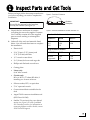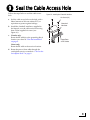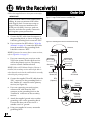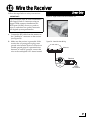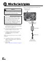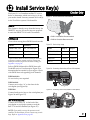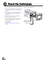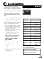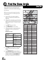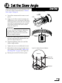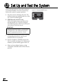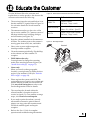
1
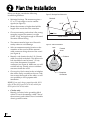
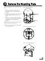
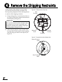
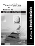
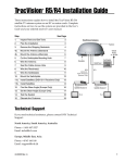
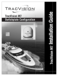
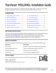
TracVision C3 Installation Guide
®
These instructions explain how to install the TracVision C3 on a vessel. Complete instructions
on how to use the system are provided in the User’s Guide.
Installation Steps
1. Inspect Parts and Get Tools ............ 3
10. Wire the Receiver(s) ....................... 12
2. Plan the Installation.......................... 4
11. Wire the Switchplate...................... 14
3. Remove the Mounting Plate ........... 5
12. Install Service Key(s)...................... 15
4. Remove the Shipping Restraints .... 6
13. Mount the Switchplate................... 16
5. Drill the Mounting Holes ................ 7
14. Install Satellites ............................... 17
6. Mount the Antenna .......................... 8
15. Find the Skew Angle...................... 18
7. Cut Out the Switchplate Hole......... 9
16. Set the Skew Angle......................... 19
8. Wire the Antenna ........................... 10
17. Set Up and Test the System........... 20
9. Seal the Cable Access Hole............ 11
18. Educate the Customer.................... 21
Who Should Install the System?
To ensure a safe and effective installation, KVH recommends that a KVH-authorized technician
install the system. To find a technician near you, please visit www.kvh.com/wheretogetservice.
Linear vs. Circular Systems
The installation process differs, depending on the type of LNB (low noise block) installed in the
antenna (linear or circular). These differences are noted throughout this guide. In general, North
American satellites require a circular LNB, while European satellites require a linear LNB.
Technical Support
If you need technical assistance, please contact KVH Technical Support:
N. America, S. America, Australia:
Europe, Middle East, Asia:
Phone: +1 401 847-3327
E-mail: [email protected]
(Mon.-Fri., 9 am-6 pm ET, -5 GMT)
(Sat., 9 am-2 pm ET, -5 GMT)
Phone: +45 45 160 180
E-mail: [email protected]
(Mon.-Fri., 8am-4:30 pm, +1 GMT)
KVH, TracVision, and the unique light-colored dome with dark contrasting baseplate are registered trademarks of KVH Industries, Inc.
All other trademarks are property of their respective companies. The information in this document is subject to change without notice.
No company shall be liable for errors contained herein. © 2008-2010 KVH Industries, Inc., All rights reserved. 54-0361 Rev. C
1
1 Inspect Parts and Get Tools
Before you begin, follow these steps to make sure
you have everything you need to complete the
installation.
Figure 1: TracVision C3 Antenna
IMPORTANT!
Radome
Always lift the antenna by the baseplate,
never by the radome (see Figure 1).
a. Unpack the box and ensure it contains
everything shown on the supplied Contents
List. Carefully examine all of the supplied
parts to ensure nothing was damaged in
shipment.
b. Gather all of the tools and materials listed
below. You will need these items to complete
the installation.
Baseplate
Figure 2: Receivers Validated for Use with TracVision C3
Standard-definition models
DIRECTV
DISH
Bell TV
D12
D11
D10
311
211k
211
3100
4100
•
Electric drill
High-definition models
•
3/16" (5 mm), 5/32" (4 mm), and
3/32" (2.25 mm) drill bits
DIRECTV
DISH
Bell TV
•
1/2" wrench or nut driver
HD not
supported
211k
211
6100
6131
•
3/4" (19 mm) hole saw and auger bit
•
Phillips and flat-head screwdrivers
•
Cutting pliers
•
Linear only:
9/64" allen wrench
•
Circular only:
RG-6 or RG-11 (75 ohms) RF cable, if
installing two or more receivers
•
Silicone sealant, RTV, or equivalent
•
7/16" open-end wrench
•
Construction adhesive suitable for the
deck
•
Augat IT1000 connector installation tool
(KVH Part #19-0242)
•
Satellite TV receiver(s) for your desired
service (see Figure 2 for a list of validated
U.S./Canadian receivers; for information on
connecting different receiver models, contact
KVH Technical Support)
3
2 Plan the Installation
Before you begin, consider the following
installation guidelines:
•
Minimize blockage. The antenna requires a
15° to 75° look angle to receive satellite
signals (see Figure 3).
•
Mount the antenna no higher than half the
length of the vessel above the waterline.
•
Choose a mounting surface that is flat, strong
enough to support the antenna’s weight
(34 lbs, 15 kg), and rigid enough to withstand
vibration without flexing.
•
•
•
•
The antenna must be kept out of line with
nearby radars to avoid damage.
Select an antenna mounting location on the
centerline of the vessel with the antenna’s
cable connectors facing the rear of the vessel
(see Figure 4).
Identify a safe location for the 3/4" (19 mm)
cable access hole in the deck. The cable access
hole should be located at least 6" (15 cm)
away from the antenna’s baseplate
connectors (see Figure 4). Make sure you will
not drill into any existing wires or aesthetic
structures inside the vessel.
Choose a dry, flat location for the switchplate
that will be easily accessible to the user. Take
into account the lengths of the cables, as well
as accessibility to the equipment after
installation.
NOTE: If you need a longer power/data cable, KVH
offers 45-foot (KVH part #32-0730-45) and 60-foot
(KVH part #32-0730-60) cables.
•
4
Circular only:
Identify a location for the grounding block
within 27 feet of the antenna, within 5 feet of
the receiver(s), and within 25 feet of a suitable
chassis ground location.
Figure 3: Blockage from Obstruction
Blocked!
Antenna
15-75˚
Mast
Vessel Platform
Figure 4: Antenna Orientation
Bow
Forward
Arrow
Radome
Mounting
Plate
Baseplate
Connectors
3 Remove the Mounting Plate
Follow the steps below to remove the mounting
plate.
Figure 5: Removing the Radome
a. Remove the eight screws and washers
securing the radome to the baseplate (see
Figure 5).
Radome
b. Carefully lift up the radome until clear of the
antenna assembly and set aside in a safe
place.
Screw and
Washer (x8)
c. Using a 1/2" wrench or nut driver, remove
the six bolts, nuts, and washers securing the
mounting plate to the baseplate (see
Figure 6).
Baseplate
NOTE: Be sure to keep the bolts in case the antenna
needs to be shipped to another location.
d. Remove the mounting plate and set it aside
for now (see Figure 7).
Figure 6: Mounting Plate Bolts (Top View)
2
3
4
1
5
6
Figure 7: Removing the Mounting Plate
5
4 Remove the Shipping Restraints
At the bottom of the antenna, two tie-wraps
prevent the internal antenna assembly from
moving during shipment. Follow the steps below
to remove these shipping restraints.
Figure 8: Tie-Wrap Locations (Top View)
Rear
Tie-wrap
a. Using cutting pliers, cut and remove the two
tie-wraps securing the antenna mechanism to
the baseplate (see Figure 8).
IMPORTANT!
Once you have removed the restraints, keep
the antenna level as much as possible and
handle the antenna unit carefully. Improper
handling might damage the unit.
b. After removing the tie-wraps, seal the four
tie-wrap holes at the bottom of the baseplate
with the plugs provided in the kitpack (see
Figure 9).
Rotating
Plate
Forward
Tie-wrap
Baseplate
Figure 9: Tie-wrap Hole Locations (Bottom View)
Forward Tie-wrap
Holes
Rear Tie-wrap
Holes
6
5 Drill the Mounting Holes
Follow the steps below to drill the antenna
mounting holes.
Figure 10: Mounting Plate Orientation
Bow
CAUTION
For your own safety, shut down vessel
power before you drill or connect wires. Test
the circuit to ensure no power is present.
Forward
Arrow
Radome
a. Place the mounting plate on the deck at the
location you chose in “Plan the Installation”
on page 4. Ensure the mounting plate’s
forward arrow points towards the bow of the
vessel (see Figure 10).
Mounting
Plate
IMPORTANT!
The locations of the mounting holes may
vary slightly from one mounting plate to the
next. Use the dimensions shown in Figure 10
for general reference only; use the mounting
plate itself as a template to lay out the holes
in the mounting surface.
Centerline
Vessel
b. Using the mounting plate as a template, lay
out the locations for the six mounting holes.
Then drill the six 3/8" (9.5 mm) holes in the
mounting surface.
Baseplate
Connectors
1.18"
(30 mm)
1.57"
(40 mm)
Forward
Arrow
16.01"
(407 mm)
26"
(660 mm)
Mounting
Plate
24"
(610 mm)
19.28"
(490 mm)
4"
(101 mm)
6.42"
(163 mm)
4.73"
(120 mm)
21.11"
(536 mm)
7
6 Mount the Antenna
Follow the steps below and refer to Figure 11 to
mount the antenna to the mounting surface.
Figure 11: Mounting the Antenna
a. Apply a bead of silicone sealant around each
mounting hole.
b. Reposition the mounting plate over the
mounting holes. Line up the holes in the
mounting plate with the holes in the
mounting surface.
c. Apply a bead of silicone sealant around each
mounting hole on top of the mounting plate.
d. Place the antenna unit on top of the mounting
plate, ensuring all holes are aligned.
e. At each hole, place a 1/4" flat washer on a
1/4"-20 x 3" bolt (supplied in the kitpack) and
insert it into the baseplate mounting hole
from above.
NOTE: Unless you need different hardware for a
thicker deck, be sure to use the bolts supplied in the
kitpack when mounting the antenna. Do not reinstall
the mounting plate bolts that you removed in
“Remove the Mounting Plate” on page 5.
f. Apply a flat washer, lock washer, and the nut
you removed in “Remove the Mounting
Plate” on page 5, to each mounting bolt from
belowdecks and tighten securely.
g. Circular only:
Reinstall the radome using the eight screws
and washers you removed in “Remove the
Mounting Plate” on page 5 (see Figure 12).
Linear only:
Do not reinstall the radome at this time.
Later, you will need to adjust the skew angle
of the antenna’s LNB.
Bolt
Flat Washer
Antenna
Baseplate
Silicone
Sealant
Mounting
Plate
Deck
Mounting Hole
Flat Washer
Lock Washer
Hex Nut
Figure 12: Radome Screws and Washers
Radome
Screw and
Washer (x8)
Baseplate
8
7 Cut Out the Switchplate Hole
Follow the steps below to cut out the switchplate
mounting hole.
Figure 13: Switchplate Cutout Dimensions
3.82"
(97 mm)
a. Using the switchplate mounting template
supplied in Appendix C on page 27, mark
and cut out a hole in the mounting surface to
accommodate the switchplate (see Figure 13).
b. Using the same template, mark the locations
for the four switchplate mounting holes.
c. Drill a 3/32" (2.25 mm) hole at the four
mounting hole locations. Later, you will
mount the switchplate using four #6 screws.
0.32"
(8 mm)
2.36"
(60 mm)
Panel Cutout
3/32"
(2.25 mm) dia
2.05"
(52 mm)
3.19"
(81 mm)
0.16"
(4 mm)
9
8 Wire the Antenna
Follow the steps below to wire the antenna.
Figure 14: Drilling the Cable Access Hole
a. At the location you chose in “Plan the
Installation” on page 4, use a 3/4"
(19 mm) hole saw to cut out a cable access
hole in the vessel’s deck (see Figure 14).
b. Smooth the edges of the hole to protect the
cables.
c. Circular only:
If you plan to connect multiple receivers,
label both ends of two RF cables for later
reference. Label one cable “RF1” and the
other “RF2.”
d. Route the power/data cable and the RF
cable(s) down through the cable access hole
in the deck. Be sure to maintain a service loop
on the deck (approximately 8" (20 cm)).
NOTE: Ensure the rubber sealing boot on the RF
cable is located on the end of the cable closest to the
antenna’s baseplate connectors.
Figure 15: Wiring the Antenna
Antenna Baseplate
e. Connect an RF cable to the antenna’s “RF1”
connector. Hand-tighten first, then tighten
with a 7/16" wrench for 1/4 turn.
NOTE: Leave the protective cap installed on the RF2
connector unless you are connecting a second RF
cable.
f. Circular only:
If you plan to connect multiple receivers,
connect a second RF cable to the “RF2”
connector.
g. Connect the power/data cable to the
antenna’s center connector and lock in place
(see Figure 15).
h. Slide the rubber sealing boot up the RF cable
until it covers the connector. This boot will
help protect the connector from the elements.
10
RF2
(optional)
RF1
Power/Data
Cable
9 Seal the Cable Access Hole
Follow the steps below to seal the cable access
hole.
a. Seal the cable access hole on the deck with a
liberal amount of silicone sealant, RTV, or
equivalent to protect against leakage.
b. Install the clamshell ventilator, supplied in
the kitpack, over the cable access hole using
three of the supplied #6 screws (see
Figure 16).
c. Circular only:
Route the RF cable(s) to the grounding block
location you chose in “Plan the Installation”
on page 4.
Figure 16: Installing the Clamshell Ventilator
#6 Screw (x3)
Clamshell
Ventilator
Power/Data
& RF Cables
Linear only:
Route the RF cable to the receiver location.
d. Route the power/data cable through the
switchplate cutout you made in “Cut Out the
Switchplate Hole” on page 9.
11
10 Wire the Receiver(s)
Circular Only
Follow the steps below to wire your receiver(s).
IMPORTANT!
Figure 17: Augat IT1000 Connector Installation Tool
If you cut an RF cable or used additional RF
cabling, be sure to terminate all RF cables
with Snap-N-Seal® F-connectors using an
Augat IT1000 connector installation tool
(KVH part #19-0242). Screw-on, push-on,
twist-on, and other low-quality connectors
will degrade system performance.
a. Connect the RF1 cable from the antenna to
the grounding block, as shown in Figure 18.
Label this grounding block connector “RF1.”
b. If you connected an RF2 cable in “Wire the
Antenna” on page 10, connect the RF2 cable
from the antenna to the grounding block.
Label this connector “RF2.”
NOTE: If you need to connect three or more receivers,
refer to Appendix A on page 25.
c. If you are connecting two receivers to the
TracVision system, decide which receiver
will be the primary receiver. The primary
receiver controls satellite selection.
NOTE: Unless a KVH Master Receiver Selector is
installed, the secondary receiver will only be able to
select channels carried on the satellite that is currently
selected by the primary receiver.
d. Connect the supplied 5-foot RF cable from the
“RF1” connector on the grounding block to
the “Satellite In” connector on the primary
receiver (see Figure 18).
e. If you are connecting a second receiver,
connect an RF cable from the “RF2”
connector on the grounding block to the
“Satellite In” connector on the secondary
receiver.
f. Attach the supplied ground wire to either
grounding screw on the grounding block.
Connect the other end of the wire to a
suitable vessel AC ground.
g. Using two supplied #6 screws, mount the
grounding block.
12
Figure 18: Grounding Block and Circular Receiver Wiring
Antenna
RF2
(Optional)
RF2 Label
Grounding
Block
RF1
RF1 Label
Grounding
Screw (x2)
Ground Wire
#6 Mounting
Screw (x2)
RF2
(Optional)
Vessel
AC Ground
RF1
(Five-foot Cable)
Primary
Receiver
TV ANT/CABLE IN
R
SATELLITE
IN
L
OUT TO TV
SATELLITE IN
AUDIO
VIDEO
S-VIDEO
PHONE JACK
Secondary
Receiver
(Optional)
TV ANT/CABLE IN
R
SATELLITE
IN
L
OUT TO TV
SATELLITE IN
AUDIO
VIDEO
S-VIDEO
PHONE JACK
10 Wire the Receiver
Linear Only
Follow the steps below to wire your receiver.
IMPORTANT!
Figure 19: Augat IT1000 Connector Installation Tool
If you cut the RF cable, be sure to terminate it
with Snap-N-Seal® F-connectors using an
Augat IT1000 connector installation tool
(KVH part #19-0242). Screw-on, push-on,
twist-on, and other low-quality connectors
will degrade system performance.
a. Connect the RF1 cable from the antenna to
the “Satellite In” connector on the receiver
(see Figure 20).
b. Make sure the receiver is grounded. If the
receiver has a 2-prong power plug, run a
ground wire from the receiver’s chassis to a
suitable ground point. If a potential exists
between AC and DC grounds, connect the
wire to the switchplate’s DC return instead.
Figure 20: Linear Receiver Wiring
Antenna
RF1
Receiver
TV ANT/CABLE IN
R
SATELLITE
IN
L
OUT TO TV
SATELLITE IN
AUDIO
VIDEO
S-VIDEO
PHONE JACK
Vessel
AC Ground
13
11 Wire the Switchplate
Follow the steps below to wire the switchplate.
CAUTION
Figure 21: Switchplate Wiring (KVH Power Supply Shown)
Power/Data Cable
From Antenna
For your own safety, disconnect vessel power
before you connect any power wires. Test the
circuit to ensure no power is present.
IMPORTANT!
The TracVision antenna requires a stable
12 VDC (4 amps continuous) power supply.
Circular systems include a 15 VDC (4 A)
power supply; linear systems do not.
However, a power supply with a Europeanstyle power cord is available for purchase
from KVH (KVH part #72-0312-01).
+15 VDC
(Red)
Ground
Gro
(Black)
a. Connect the antenna’s power/data cable to
the switchplate’s power/data connector and
lock in place (see Figure 21).
b. Crimp the supplied terminal connectors onto
the power supply’s DC power wires.
Power Supply
c. Carefully push the connectors onto the
switchplate’s input power terminals
(see Figure 21).
NOTE: Strain-relieve the wires to ensure a reliable
connection.
d. Connect the AC power cord to the power
supply. Then plug the power cord into the
vessel’s AC power.
e. Linear only:
Skip to “Mount the Switchplate” on page 16.
14
AC Power Cord
100-240 VAC
To Vessel AC Power
12 Install Service Key(s)
Find your U.S. or Canadian satellite TV service
below to determine which service key(s), if any,
you need to install. Store any unused service keys
in the TracVision system’s Welcome Kit.
Circular Only
Figure 22: Recommended DISH 1000 Satellites
DIRECTV
The system is already set up from the factory for
DIRECTV service. No service keys are required
to track the DIRECTV 101 and 119 satellites.
= DISH 129 Satellite Recommended
DISH Network
= DISH 61 Satellite Recommended
Choose from among three DISH Network modes:
Figure 23: Service Keys Usage
Mode
Satellites
DISH 1000/129*
110, 119, and 129
Mode
DISH 1000/61
110, 119, and 61
DISH 500
110 and 119
* Optional Master Receiver Selector (KVH part #72-0412)
required for automatic satellite switching; multiswitch
(KVH part #72-0310) required for manual switching; see
Appendix A on page 25.
Select a DISH 1000 mode for DISH Network’s
TurboHD service. Use the map in Figure 22 to
determine the best mode for your region. Check
with DISH Network regarding local channels.
DISH 1000/129
No service keys are required.
DISH 1000/61
Connect service key “A” to the front of the
switchplate (see Figure 24).
DISH 500
Connect both service keys to the switchplate (see
Figure 24 and Figure 25).
Key A
Key B
DISH 1000/129
-
-
DISH 1000/61
Connect
-
DISH 500
Connect
Connect
-
Connect
Bell TV
Figure 24: Connecting Service Key A (Front of Switchplate)
MAINTENANCE
MAINTENANCE
A
A
Figure 25: Connecting Service Key B (Back of Switchplate)
B
B
Bell TV (Formerly ExpressVu)
Connect service key “B” to the back of the
switchplate to set up the system to track the
Bell TV 91 and 82 satellites (see Figure 25).
NOTE: If you wish to set up the system to track
satellites not listed above, do not connect any service
keys. Refer to Appendix B on page 26.
15
13 Mount the Switchplate
Follow the steps below to mount the switchplate.
a. Fit the switchplate flush into the panel cutout
you made in “Cut Out the Switchplate Hole”
on page 9.
Figure 26: Switchplate Mounting
urface
ting S
Moun
h
Switc
b. Drill out four 5/32" (4 mm) mounting holes
in the switchplate’s screw cavities (see
Figure 26).
r
Cove
Front
c. Mount the switchplate to the mounting
surface using four #6 screws.
d. Gently snap the switchplate cover onto the
front of the switchplate to conceal the
mounting screws.
e. Circular only:
Skip to “Set Up and Test the System” on
page 20.
16
plate
5/32" ( 4 mm)
Mounting Hole (x4)
#6 Screw (x4)
14 Install Satellites
Follow the steps below to configure the
TracVision system to track a pair of linearly
polarized satellites. To complete this procedure,
you will need to connect a PC to the antenna and
use the KVH Flash Update Wizard to install your
satellites.
Figure 27: Switchplate ON/OFF Switch
ON
OFF
NOTE: The Flash Update Wizard is available to
KVH-authorized dealers through the KVH Partner
Portal.
a. Connect a PC to your TracVision system, as
described in the Flash Update Wizard’s Help
file. Then enter the commands below into the
Wizard’s “Antenna Comms” window.
NOTE: For details on entering antenna commands,
refer to the Flash Update Wizard’s Help file.
b. Apply power to the TracVision system and
set the switchplate’s POWER switch to the
ON (|) position (see Figure 27). Wait two
minutes for system startup.
c. In the Wizard’s “Antenna Comms” window,
type HALT then press Enter.
d. Choose your desired satellites from the
satellite library (see Figure 28).
e. Type the following command then press
Enter. Be sure to use the proper install
name(s) for your selected satellite(s).
SATINSTALL,<SAT_A_NAME>,
<SAT_B_NAME>
NOTE: Select the satellite you want to track first as
“SAT_A”. Once the procedure is complete, the
antenna will begin tracking that satellite.
f.
Type ZAP then press Enter to restart the
antenna. Wait two minutes for system
startup.
g. Keep your PC connected to the antenna. You
will need to enter additional commands in
the following steps.
Linear Only
MAINTENANCE
Figure 28: Linear Satellite Library
Satellite Name
Longitude
Install Name
Arabsat
26° E
ARABSAT
Astra 1
19° E
ASTRA1
Astra 2N
28° E
ASTRA2N
Astra 2S
28° W
ASTRA2S
Eutelsat W3A
7° E
EUTEL_W3A
Hispasat
30° W
HISPASAT
Hotbird
13° E
HOTBIRD
Hotbird WB
13° E
HOTBIRDWB
Nilesat 101
7° W
NILESAT
Pas 9
58° W
PAS_9
Sirius
5° E
SIRIUS
Thor
8° W
THOR
Turksat 1C
42° E
TURKSAT1C
None
-
None
Figure 29: Satellite Installation Example
Installing ASTRA2S and HOTBIRD
HALT
SATINSTALL,ASTRA2S,HOTBIRD
ZAP
17
15 Find the Skew Angle
Follow the steps below to determine the ideal
skew angle for your location and selected
satellite(s). You will set the LNB to this angle in
the next step.
TIP: Your service provider might also be able to
provide you with the correct skew angle for your
selected satellite.
a. Using a GPS or the map and table in
Figure 30, determine your latitude and
longitude.
b. Using the PC connected to your TracVision
system, enter the commands below into the
Flash Update Wizard’s “Antenna Comms”
window.
c. Type HALT then press Enter.
d. Type DEBUGON then press Enter.
e. Using the table below, type the following
command to enter your latitude and
longitude.
GPS,XX,A,YYY,B
Variable
Value
XX
Latitude (0-90)
A (Enter S or N)
YYY
B (Enter E or W)
f.
S (South)
N (North)
Longitude (0-180)
E (East)
W (West)
Type ZAP then press Enter to restart the
antenna. Wait two minutes for system
startup.
g. Type SKEWANGLE then press Enter to
display the skew angle for your location and
currently selected satellite. If you installed
multiple satellites, type AVGSKEW then
press Enter to display the average skew.
18
Linear Only
Figure 30: Approximate European Latitude/Longitude Values
2
1
5
6
10
13
12
4
7
9
8
3
14
11
16
15
17
21
Grid #
1
2
3
4
5
6
7
8
9
10
11
12
13
14
15
16
17
18
19
20
21
22
23
24
19
18
22
23
Latitude
67° N
67° N
67° N
65° N
63° N
63° N
63° N
57° N
57° N
57° N
55° N
53° N
53° N
50° N
47° N
47° N
43° N
43° N
43° N
43° N
36° N
36° N
36° N
36° N
20
24
Longitude
7° W
7° E
22° E
45° E
7° W
7° E
22° E
7° W
7° E
22° E
40° E
7° W
7° E
22° E
7° W
7° E
7° W
7° E
22° E
37° E
7° W
7° E
22° E
37° E
16 Set the Skew Angle
Follow the steps below to set the antenna’s LNB
to the skew angle you determined in “Find the
Skew Angle” on page 18.
a. Turn off the antenna and disconnect vessel
power.
b. Using a 9/64" allen wrench, loosen the two
LNB bracket screws securing the LNB in the
following manner: loosen one screw one full
turn, then loosen the second screw one full
turn; repeat until the LNB can be rotated
freely (see Figure 31).
Linear Only
Figure 31: LNB Bracket Assembly
LNB
Bracket
LNB
LNB Bracket
Screws
IMPORTANT!
Be sure to alternate loosening or tightening
the LNB bracket screws. Failure to do so
might cause unequal pressure on the LNB,
which can impair reception.
c. Rotate the LNB to align the skew arrow with
the skew angle that you determined in the
previous step (see Figure 31).
d. Alternate tightening each screw until the
LNB no longer rotates.
Negative
Skews
Positive
Skews
SKEW
-20˚ Skew
e. Tighten the screws one additional 1/4 turn.
f.
Reinstall the radome using the eight screws
and washers you removed in “Remove the
Mounting Plate” on page 5 (see Figure 32).
g. Restore power to the TracVision system.
Figure 32: Radome Screws and Washers
Radome
Screw and
Washer (x8)
Baseplate
19
17 Set Up and Test the System
Follow the steps below to set up the system for
your desired satellite TV service (if necessary)
and test the system for proper operation.
Figure 33: Switchplate ON/OFF Switch
ON
a. Stop the vessel in a blockage-free area. The
antenna requires an unobstructed view of the
sky to receive satellite signals.
b. DISH Network or Bell TV only:
Follow the step-by-step setup instructions
provided in the User’s Guide to configure
your DISH Network or Bell TV receiver(s) for
your selected TracVision mode.
IMPORTANT!
Each DISH Network or Bell TV receiver must
be configured to work with the TracVision
system, as explained in the User’s Guide.
c. Turn on the receiver(s) and TV(s). For details
on operating the receiver, refer to your
selected receiver’s user manual.
d. Set the switchplate’s POWER switch to the
ON (|) position (see Figure 33). Within a few
minutes, a picture should appear on the TV.
e. When you have finished testing, set the
switchplate’s POWER switch to the OFF (O)
position.
20
OFF
MAINTENANCE
18 Educate the Customer
Give the Welcome Kit to the customer and
explain how to use the product. Also be sure the
customer understands the following:
•
•
•
The receiver(s) must be activated before it can
decode satellite TV signals. Refer to Figure 34
for activation details for North American
receivers.
The antenna must have a clear view of the
sky to receive satellite TV. Common causes of
blockage include trees, buildings, bridges,
and mountains (see Figure 35).
Keep the radome installed on the antenna at
all times. The radome protects the antenna’s
moving parts from wind, rain, and debris.
•
Heavy rain or snow might temporarily
interrupt satellite reception.
•
Clean the antenna periodically. Dirt buildup
on the radome can affect satellite TV
reception.
•
DISH 1000 modes only:
You might need to change the operating
mode when traveling between regions (see
“Install Service Key(s)” on page 15).
•
Linear only:
When you travel to other geographic
locations, you might need to adjust the skew
angle of your antenna’s LNB (see “Find the
Skew Angle” on page 18).
•
Please register the system with KVH. The
registration process is quick, easy, online, and
ensures the best possible service from KVH.
Visit www.kvh.com/register or refer to the
Product Registration Form for details.
•
The vessel must be located within the
selected satellite’s footprint in order to
receive its signals. To view satellite coverage
maps, visit www.kvh.com/footprint.
•
If you need to paint the radome, use only
non-metallic automotive paint without a
primer coat. Any paint that contains metal
will block satellite signals and impair
reception.
•
Refer to the User’s Guide for complete
operation and troubleshooting information.
Figure 34: North American Receiver Activation Information
Service:
Call to Activate:
DIRECTV
1-866-551-8004
(24 hours, 7 days a week)
DISH Network
1-866-399-8509
(Mon.-Fri., 8:30am - 5pm ET)
Bell TV
1-888-759-3474 (SKY-DISH)
(24 hours, 7 days a week)
Figure 35: Blockage Example
Blocked!
21
Appendices
This section includes the switchplate mounting template and provides supplemental
instructions for special or advanced configurations.
Contents
A. Connecting 3 or More Receivers ............... 25
B. Choosing Alternate Satellites..................... 26
C. Switchplate Template ................................. 27
23
A Connecting 3 or More Receivers
If you need to connect three or more receivers, or
you set up the system for DISH Network’s 129
satellite (one or more receivers), install an active
(powered) multiswitch or Master Receiver
Selector between the grounding block and the
receivers, as shown in Figure A-1.
Circular Only
Figure A-1: Wiring Up to 4 Receivers
Antenna
NOTE: If you need to connect more than four
receivers, please contact KVH Technical Support.
Active Multiswitch
The optional Eagle Aspen multiswitch with AC/
DC power supply (KVH part #72-0310) allows
you to connect up to four receivers to the
TracVision system. However, since a multiswitch
interrupts satellite switching communications
between the receiver and the antenna, you will
need to manually switch between your selected
satellites.
With the TV/SAT Switch (KVH part #01-0245)
installed, you can manually switch between a
pair of satellites at the press of a single button.
For alternative manual switching options, such
as typing switch commands via a PC, please
contact KVH Technical Support.
RF1
RF2
Grounding Block
AC Power In
100-240 VAC
50-60 Hz
Vessel
AC Ground
IMPORTANT!
Multiswitch connections
for DISH 1000/129:
RF1=13V; RF2=18V
DC Power
Supply
Power/DC
18V/RF1
Active Multiswitch
Receiver 1
OR
Receiver 2
13V/RF2
Master Receiver Selector
Receiver 3
Receiver 4
IMPORTANT!
The TV/SAT Switch only supports dualsatellite configurations, so it cannot be used
with three-satellite DISH 1000 modes. If you
need to connect three or more receivers in a
DISH 1000 mode, the best option is the
Master Receiver Selector (see below).
Receiver #4
TV ANT/CABLE IN
R
SATELLITE
IN
L
OUT TO TV
SATELLITE IN
AUDIO
VIDEO
S-VIDEO
PHONE JACK
Receiver #3
TV ANT/CABLE IN
R
Master Receiver Selector
SATELLITE
IN
L
OUT TO TV
SATELLITE IN
The optional KVH Master Receiver Selector
(KVH part #72-0412) is an enhanced multiswitch
that provides the following capabilities:
AUDIO
Automatic satellite switching in any
operating mode, including DISH 1000/129.
•
Support for multiple receivers.
•
Capability for the user to select, at any time,
which receiver controls satellite selection.
Simply turn the knob!
S-VIDEO
PHONE JACK
Receiver #2
TV ANT/CABLE IN
R
•
VIDEO
SATELLITE
IN
L
OUT TO TV
SATELLITE IN
AUDIO
VIDEO
S-VIDEO
PHONE JACK
Receiver #1
TV ANT/CABLE IN
R
SATELLITE
IN
L
OUT TO TV
SATELLITE IN
AUDIO
VIDEO
S-VIDEO
PHONE JACK
25
B Choosing Alternate Satellites
Although most installations do not require
different satellites than those listed in “Install
Service Key(s)” on page 15, you may set up your
TracVision system to track a pair of alternate
satellites.
To do so, you need to connect a PC to the antenna
and use the KVH Flash Update Wizard to install
your alternate satellites. The TracVision system
includes a satellite library that contains the most
commonly used satellites. Follow the steps below
to configure the system to track satellites from
this satellite library.
Circular Only
Figure B-1: Circular Satellite Library
Service
Satellite
Install Name
DIRECTV
72° W
DSS_72
101° W
DSS_101
110° W
DSS_110
119° W
DSS_119
61° W
ECHO_61
110° W
ECHO_110
119° W
ECHO_119
129° W*
ECHO_129
DISH Network
NOTE: The Flash Update Wizard is available to
KVH-authorized dealers through the KVH Partner
Portal.
a. Connect a PC to your TracVision system, as
described in the Flash Update Wizard’s Help
file. Then enter the commands below into the
Wizard’s “Antenna Comms” window.
Bell TV
(ExpressVu)
82° W
EXPRESSVU
NOTE: For details on entering antenna commands,
refer to the Flash Update Wizard’s Help file.
91° W
EXPRESSTV
None
-
NONE
b. Set the switchplate’s POWER switch to the
ON (|) position. Wait two minutes for system
startup.
* Master Receiver Selector or active multiswitch
required for DISH Network’s 129 satellite; see
Appendix A on page 25.
c. Type HALT then press Enter.
d. Choose your desired satellites from the
satellite library (see Figure B-1).
e. Type the following command then press
Enter. Be sure to use the proper install
name(s) for your selected satellite(s).
SATINSTALL,<SAT_A_NAME>,
<SAT_B_NAME>
NOTE: Select the satellite you want to track first as
“SAT_A”. Once the procedure is complete, the
TracVision system will begin tracking that satellite.
f.
26
Type ZAP then press Enter to restart the
antenna. Wait two minutes for system
startup.
Figure B-2: Example of Choosing an Alternate Satellite
Installing DISH Network 119° W Only
HALT
SATINSTALL,ECHO_119,NONE
ZAP
0.16"
(4 mm)
2.36"
(60 mm)
0.32"
(8 mm)
3.19"
(81 mm)
Panel Cutout
3.82"
(97 mm)
2.05"
(52 mm)
3/32"
(2.25 mm) dia
C Switchplate Template
27