1
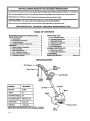
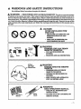
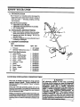
IMPORTANT
MANUAL
Do Not Throw Away
Operator's
Manual
Model No.
257.798040
Always
Wear Eye Protection
During
Operation
SEAR$/CRFIFTSMnNo
ELECTRIC
TRIMMER
A WARNING:
and Follow _
Warnings and
Safety Instructions.
Failure To
Do So Can Result in Serious in.
juts
DOUBI_
• Assembly
' •
• Operation
Sold by Sears,
534886690-1-09/28/92
Roebuck
and Co., Hoffman
INSULATED
Maintenance
• Repair
Estates,
Ill. 60195
Parts
USA
© Sears, Roebuck and Co., 1992
ONE
Lmmmu
ONcm rsyaN WSEUWACKER®
[_ Fc_ One Year from _
of purchase, when this Electric Line Trimmer is maintained and used according tqthe Operating aud _
N maintenance instructions m the operator's mauual, Sears will repair free of charge any defect in material or workmanship. H
J_ This warranty excludes nyl°n line vr any °ther parts width are expendable parts and _me
I_ If this Electric Line Trimmer is usedforcommev_ orre_tal_es,
i_WAPaAN_Sm_CS
|_
m AVAm_LE BYPm_GTHEUNrr
SEAP_,ROEBUCKAND_
WARNtNGSAND SAFETY INSTRUCTIONS
KNOW YOUR I]NIT ..........................
iL Introduction
............................
B. Unpacking Instructions ..................
C, Carton Contents .........................
D. Double Insulation Construction ...........
ASSEMBIN ..................................
A. Assist Handle Attachment
................
B. Tube Assembly ...........................
C. Shield Attachment
.......................
D. Pre-Operation
Checks .......
.. ..........
E. Extension Cord Attachment
..............
F. Operating Positlon .......................
...
d_g
n°_
this warrantydoesnotapply.
_O_m_A_F_ST sa_mss_
D_D/817WA
TABLE
w_
SEARS'I"OWER
_e"
N
:
___
HOFFMA_I_,STATES,
IL6019B
3
5
5
5
5
5
6
6
6
6
7
7
7
USING YOUR UNIT
A_ Line Trimmer Safety .....................
B. Operating Instructions ...................
Adjustment
Handle
Trigger
Switch
MODEL:
Air Vents
MOTOR:
.vH
Shield
CUTTING PATH:
CUTTING LINE:
LINE FEED:
-2-
8
9
C. Adjustable Handle .......................
9
D. Trimmer Line Advance ...................
9
E. Cutting Methods ........................
9
E Line Replacement .......................
I0
GENERAL I_ENANCE
/_ Maintenance Safety ......................
11
B. Trouble Shooting Chart ..................
11
ACCESSORIES
.............................
11
PARTS AND SERVICE ...............
Back Cover
/
WEIGHT:
_
OF CONTENTS
SPECIFICATIONS
AMPS:
_
_ G
Trimmer Head
It
WARNINGS
AND SAFETY
INSTRUCTIONS
(SeeAdditional
SafetyInstructions
throughoutthisManual)
It WARNING
- THIS POWER
UNIT CAN BE DANGER
O US! This unit can cause serious injury
or blindness to the operator and others. When using an electric trimmer, these basic safeW precautions must be followed to reduce the risk of injury, fire, and electric shock. Failure to follow all instructions can result in blindness or
other serious injur_. The operator is respous_le for followingthe wernings and instructions in _
manual and on the
unit. Read the entire Operator's Manual before assembling
and using this unit! Restrict
the use of this
unit to persons who read, understand,
and follow the warnings and instructions
in this manual and on
the unit.
ill
i,i
i
It
DANGER
NEVER
USE BL._DES
WITH
THIS LW1T.
- THE BLADE CANCOME OFFAND
8ERIOUSLY
OTHERS.
- rms _zs
L_
Thro"__
_
_
-
-_
Boots
60 Foot
(20 meter)
Hazard Zone
DESIGNFn_
FOR
USEONLY
It WARNING
OBJECTS
a_d
HURT YOU AND
VIOLENTLY.
INJURED.
YOU
CAN BE BLINDED OR
WEAR EYE AND LEG PROTECTION.
It WARNING
HAZARD ZONE FOR THROWN
OBJECTS
-
TRIMMER _CAN
THROW OBJECTS
VIOLF, NTI_
-
OTHERS CAN BE BLINDED OR
INJURED.
KEEP PEOPLE AND ANIMALS 30
-
FEET (10 METERS)
It
WARNING
OPER_TOR'S
Operator's
Mauu_
Safety
Labels
AWAY.
MANUAL
-
FOLLOW ALL WARNINGS
INSTRUCTIONS.
AND
-
FAILURE
TO DO SO CAN RESULT
SERIOUS
INJURY_
IN
-S-
WARNINGS
A OPERATOR
AND
SAFETY
INSTRUCTIONS
SAFETY
A
1. DRESS PROPERLY--Always
wear eye protection
when operating,
servicing,
or performing_naintenauco on your unit....
2. _ways wear heavy,longpants,boots,and gloves.
wearingsafetylegguardsisrecommended. See "Accossones."
Do notgobarefootorwear sandals,short
pants,jewelry,
looseclothing,
orclothing
withloosely
.hanging
straps,
ties,
tassels,
etc.;
theycan be caught
m moving parts.Securehairsoitisabove shoulder
len=_.Beingfully
coveredwill
helpprotect
you from
pieces of toxic plants such as poison ivy thrown by
trimmerhead which couldbe more ofa hazardthan
touchingtheplantitself.
3. STAY ALERT--Do
not operatethisunitwhen you
aretired,
ill,
orunder theinfluence
ofalcohol,
drugs,
or medication.
4. AVOID UNINTENTIONAL
STARTING OF THE
UNIT--Never
carry the unit with your finger on
the switch. Be sure the switch is in the off position before connecting the extension
cord,
5. Restrict theuseof this unit to persons who read, understand, and to]low the warnings and instructions
in this manual and on the unit.
A ELECTRICALSAFETY
1. Use only a 120 A-C. voltage supply as shown on the
name plate of the unit.
2. Avoid dangeroussituations.
Do notuseinthepres_
onceof_le
liquids
orgasestoavoidcrea_g a
fire or explomon and/or causing damage to the unit.
3. WARNING--TO
REDUCE THE RISK OF ELECTRICAL SHOCK--Do
not use in damp or wet locations or around swimming pools, hot tubs, etc. Do not
ofe_ectricale
tosnow,rain,orwatertoavoidthepossibility
shock.
4. WARNING--Use
extension
cords spec_cally
marked as suitable for outdoor appliances having
electrical rating not less than the rating of the unit.
An undersized extension cord will cause a drop in line
voltage resulting in loss of power and overheating. If
in doub%use the next heavier gauge. The smaller the
gauge number, the heavier the cord. (NOTE: Figv.re 4 shows the correct size to be used depending on
the cord length).
5. DO NOT ATTEMPT
TO REPAIR UNIT--Inspect
insulation
and connectors
on unit and extension
cord
before each use. If there is any damage, do not use until damage isrepaired
by qualified
service
personnel
6. Never carrythe unitby theextensioncordor yank
theextension
cordto disconnect
theunit.
7. To reducethepossibility
oftheextenslon
corddlsconnectipg_ from the unit during operation, tie the cords
togeto_e_eer
as shown in FigureNO TAG. Insert cord
socket on the unit into extension cord receptacle.
8. Do not use the unit if the switch does not turn the unit
on and off properly. Repairs to the switch must be
nmde by qualified service personnel
9. Keep the extensioncord Clearof operatorand 0bstacles
atalltimes.Do notexposecordstoheat,oil,
water,or sharpedges.
10.Avoidany body contactwith any groundedconductor,
sucha metalpipesorwirefences,
toavoidthepossibillty
ofelectric
shock.
If situations
occur
Authorized
Service
L Inspectentire
unitbeforeeachuse.Replacedamaged
parts.Make sureallfasteners
areinplaceand secure!yfastened.
2. Replace trimmer head parts that are cracked,
chipped,or _d
befo_ usingtheunit
3. Use only.051"diameterline.Never usewire,rope,
string,
etc.
4. Install
theshieldproperly
beforeusingtheunit:
5. Use onlythespecified
trimmer head. Make surethe
trimmer head isproperlyinstalled
and securely
fastened.Referto_Assembly."
6. Use only genuine SF._RS accessories as recommended for this unit.
A CUTTING
SAFETY
1. Inspectareatobecutbeforeeachuse.Remove objects
(rocks,
broken glass,
nails,
wire,string,
etc.)
which
canbe thrown orbecome entangled
in trimmerhead.
2. KEEP CHILDREN AWAY--Keep
othersinclu_g
children,
animals,
bystanders
and _elpers
outside
the
60 foot(20meter)Hazard Zone.Stoptheunit_ediat_y if you are approached.
3. Avoid_a_'dental _s-t@A-tlng.
Be sure the switch is in the
"O_
positlon and keep your hand and fingers away
from the switch while connecting the unit to an extension cord or when carrying a unit connected to a
power source.
4. Stop the unit and disconnect the power source when
notin use.
5. DO NOT OVERREACH OR STAND ON UNSTABLE SUPPORT--Keep
firm footing and balance.
Do not over-reach.
7". Keep
trimmer
head your
below
waistThe
level
Do nottheraise
unit above
waist.
trimmer head
can come dangerously close to your body.
8. Keep all parts ofyour body away from trimmer head
unit is running,
9. when
USE UNIT
PROPERLY--Use
only fior jobs explainedinthismanual Do not force the unit.
A MAINTENANCE
SAFETY
1. Maintain the unit according to recommended prcoedures. Keep cutting line at the proper length.
2. Have all internal service performe_ by qu_tlified service personnel
toavoidcreating
a hazardand!orvoid-
ingyourwarranty._
3. DISCONNECT
UNIT FROM THE POWER SUPPLY beforeperformingmaintenance.
4. Never douse or squirt the unit with water or any other liquid. Clean with a damp sponge. See '%Maintenance ----Storage. _
5. Keep the air vents clean and free of debris to avoid
overheating the motor. Clean after each use. See
_Specificatious" for locations.
6. Use only genuine SEAR_ replacement parts as recommended.
A
TP_SPORTING
AND
STORAGE
I. Hand carry the unit with the motor stopped.
2. Allow the unit to cool and secure the unit_before storing or transportlng in a vehicle.
!:'
3. Storetheunitsothe Rue limltor cannotaccidentally
c_e mjur_.
4. STORE ITNIT INDOOI_S--Store unitunplugged
ina high,dryplaceoutofreachofchildren.
which are not covered in this manual,
use care and good judgment.
Contact your
Dealer if you need assistance,
SAVE THESE
-4-
.... (C6ntinued)
UN/T SAFETY
INSTRUCTIONS
II
I
IIIIIIIIIII IIIIIIIIIIIIII
IIII
I
I
_
IIII
iiiiii
i
iii iiii ]1
KNOW YOUR UNIT
I I
[
IIII
|1
II I
II
II
I I
A. INTRODUCTION
YourTrimmer is a versatile product developed for
large lawns and to make short work of a variety of
lawn care tasks -- trimming, scalping, mowing,
and sweeping.
Special Features
Include:
• Adjustable
Assist Handle
• Adjustable
Top HandlefI_ube Assembly
• 15" Cutting Path
B. UNPACKING
INSTRUCTIONS
L After removingthe contents from the carton,
check parts against the Carton Contents list,
2. Examine the parts for damage. Do not use
damagedpar_.
3. Notlfy your SEARS store immexZia_eIy if apart
is missing or dam_ed.
C. CARTON CONTENTS
KEY
NO.
1.
-Loose
2.
3.
4.
5.
6.
7.
8.
9.
10,
11.
12.
DESCRIPTION
QTY P/N
Trimmer
1
257.798040
Operator'sManual(L_t_ho_a)
1
534886690
Parts Bag Contents:
AssistI-Iandle
Screw-Assist Handle
Knob - Assist Handle
hmert - Assist Handle
Screw - Tube
Locknuts - Tube
Shield
Front Guard
Screw - Shield
Washer
Yoke
1
1
1
2
2
2
1
1
2
S
1
5346834O5
534828401
534683305
534719105
534774701
534828300
534685225
534677215
534790303
534828702
534683205
D.DOUBLE
INSULATION
CONSTRUCTION
'
This unit is Double Insulated
to help protect
against
electric
sho&k. Double insulation con,
struction consists of two separate _tayers" ofelectri' :
cal inmlatiow
•
Tools built with this insulation system are not intended to be grounded. As aresult, the extension cord
used with your unit can beplugged
120 voltelectrical outlet
into any _udard
Safety precautions must be observed when operating any electrical tool The double insulation
systemonly provides added protection
againstinjury
resul"_.ugfrom an internal electrical insulation
_.lLU'e.
All electrical
A WARNING
repairs .to this :m_it, including
housing,
switch, motor, et_ must be diagnosed
andrepairod
by qualifiedservice
personnel.
Re..
pla .c_nent
parts, ,for.
a: .double
insulated
appli_mce must be ide_ti_
to the parts they,re=
place. A double insulated
applisnce
is marked
with the words"DOUBLE
INSULATION
or
"DOUBLt', R_SULATED," _The symbol (square
within a square) _
rosy also be marked on the
appliance.
Failure to have the unit repaired by
Sears qualified service personnel
can cause the
double insulation
construction
to become ineffective and result in serious inj_,.
. i
ASSEMBLY
If your unit is received
assembled,
adjusted for the operator.)
repeat
all steps in this section
to be sure assembly
is correct
and is
PREPARATION
This Operator's Manual is designed to help you assemble and safely operate this unit. It is important that you read
the entire manual to become f_zitiar with the tool before you begin assembly.
TOOLS NEEDED FOR ASSEMBLY."
L Phillips Screwdriver
2. Adjustable
Wrench
A.ASSIST
HANDLE
ATTACHMENT
1.
Pass the wire harness through the slot in the bottom ofthe yoke. Figure 1 (inset),
2.
Slide the yoke onto the upper tube as shown in
Figure 1 (inset).
Place the assist handle over the yoke. Assemble
parts as shown in Figure l.
Place the boltin the a_ist handle. Figure t.
Thread the knob onto the bolt and tighten unti!
the parts are snug.
3.
4.
illllllllllllll
B. TUBE
1.
H
Assist
Handle
Yoke
/
Washer
Figm"e 1
illliw
ASSEMBLY
Slide the outer tube UP the lower tube and over the
end of the upper tube until the screw holes are
aligned. Figure 2.
Lower Tube
When performing step 2, take care not to
pinch, cut, or twist the ale
or wire harness.
2.
Insert screws through holes in tubes.
3,
Thread the loclmuts
securely.
C. SHIELD
.
Figure 2.
onto the screws and tighten
ATTACHMF2qT
Aw Nm
I
The shield.must
be properly
installed.
The[
shield provades partiaI protection
from the risk[
of thrown objects to the operator _
othe.rs and [
is equipped with aline limiter which cuts line to]
the proper length.
[
Failure to install
the shield
in the imsition[
shown i_ Figuro 3 can result in serlous m3ury to [
the operator. Carefully follow assembly "mst_ c- I
#lolls when attaching
the shield to the unit. Fig- I
In'e
Screw
Holes
Rear
Shield
Screw
Holes
Front
Shield
_.
The line limiter (on the underside
the shield) is sharp and can cut you.
1.
Slide the rear stfietd end the front shield
grooves on the trimmer housing. ,Figure
]_T_O_T_:Take care not to trap the cuttingline
the shields, or between one of the shields
lz_nmer housing.
-6-
L/miter
Fig e3
of
into the
3.
between
end the
2.
Align the screw holes in the rear shield with the
screw holes in the fi_nt shield. Figure 3.
3. Thread screws into the holes. Tighten securely.
_T_Q_E: Remove the protective cover from the line
limiter before using the unit,
D.PRE-OPERATION
.
A
Review all Warnings
this manual,
CHECKS
WARNING
and Safety
Instructions
in[
c. Use only
,065" diameter
line. Never use
wire, rope, string, etc.
d. Use onlywith
the shield properly attached.
e. Use only the specified
"trimmer head. See
."Specifications." Make sure the trimmer head
is properly installed and securely fastened.
Refer to "Using Your Unit."
f. Use only genuine SEARS accessories
or attachments
recommended
for this tool
!
t
1. Before operatmgyour
tool, always.
a. I_t
the entire tool before each use. Replace damaged parts. Make sure a]] fasteners are
in place and securely fastened.
b. Replace
trimmer
head
parts
that
are
cracked,
eJxipped, broken, or _ed
in
any other way before using the tool.
i
E.EXTENSION
iii
I
,,,I,HI I
CORD ATTACHlVlENT
1.
Use only a 120 A.C. voltage supply as shown
on the nameplate of the unit to power your blower.
2. The extension cord used to reach the power
source must be:
a. Specifically
marked
as suitable
for outdooruse. The cord mu_t be marked with the suf-
fix_WH _
b. Heavy enough to carry the current from
the power sourem the _
length of the extension cord to the unit. Otherwise, loss of
power and overheating can occur _using damage to tho unit. Refer toFigure4
for_um
wire gauge recommendations. The cord m_ be
marked with the proper wire gauge. (AFpropnate extension cords are available.)
In good conditioxL
Cord _nmlation must be
intact with no cracks or deterioration. Plug conn_a-s mnst _ un_
3. Secure extension
cord to unit as follows:
v. Tie the cords together as shown in Figure 4.
b. Insert the Cord Socket on the unit into the Extension Cord Receptacle. Figure 4.
F. OPERATING
1.
POSITION
Before operating
the unit, stand as shown in
Figure 6 and chec_ for the follo_.
LeR arm fully extended, hand holding Assist
GAUGE
RECOMMENDATIONS
'
i -o0 .I o- oOI T.
.......
,,
120
16
_W.G.*
14
_W.G.*
12
A.W.G.*
Cord
Socket
OPERATING
POSITION
Handle.
b. Right arm slightly bent, hand holding haudle.
c. Unit below waist level
d_ Weight of -_it evenly
distn?_uted between
a.v£_.
e, Without operator bending over, the Trimmer
Head is near and parallel to the ground and
easily contacts the material to be cut.
2.
Adjust Assist Handle
to a comfortable po_fiom
i i
i LLLLLL
J
I
ml II I
-TOTES
-7-
I
mll
II
iii
|1
II
"
II
I
USING YOUR
II
A_
Face
Shield
WARNING-THROWS
Boots
ii
i
60Foot
/
OBJECTS
The rapidly moving line causes objects to be
thrown violently. The shield will not provide
complete protection to the operator or others.
The operator
must wear a safety face
shield or goggl_e_
Always wear heavy,
longpants
and boots. Keep others at least
30 feet (10 meters) awa_
.
_, _/(20
_
i
_k
WARNING
meter)
- HAZARD ZONE
This unit will throw objects and cut. Keep
others including
children,
_s,
bystanders, and helpers at least 30 feet (10
meters) away from the operator audunit.
Stop the umt if you are approached.
Hazard Zone
i
J
A
WARNING-
DAMAGED
TRIMMER
HF_kD
Trimmer headparts that are chi'pped,cracked,
broken, or dan_ged in any other way can flvy
apert and cause serious injury. Do not use.
Use Only Genuine
SEARS
Replacement Parts
L,ll
•
i
LINE
TRIMMER
i
i/
ivy thrown by the Trimmer Head whi_ could
the plant it-
c. Do not operate this unt.t when you are
tired, ill or under the influence
of alcohoL drugs, or medication.
2. UNIT SAFETY
a. Inspect the entire unit before each use.
Replace damaged p_-_cs. Make rareallfastenersare in phce and securely fastened.
b. Use only .065" dimneter llne.
Never use
wire, rope, string,.eta
c. Be sure the shield
is properly
using
the
attached.
NOTES
ii
d. Make sure the trimmer head is properly
installed
and securely
fustened_ Refer to
the "Using Your Unit" section.
e. Use only genuine SF_kRS accessories
or
attachments
as recommende_
SAFETY
be more of a hazard than touching
parts-before
,
i|
1. OPERATOR SAFETY
m Always wear a face s_ffety shield or goggles. See =Accessorles. _
b. Always
wear heav_
long lmmts, boots,
and gloves. See _Accesseries. _ Do not wear
loosed_Idng, jew_elry,
short pants, sandals or
go barefoot. Secure bah- so it is above shoulder
]engttL Being fully covered will help protect
you from piece s of toxic phnts such as poem
-8-
_u_m_t.Iacedamaged
q
CUTTING SAFETY
a. Inspect
the area to be cut before each
Remove objects (.ro_.,broken glass,
_, wire, s_:
etc.) which, can be thrown or
become entangledinthetrimmer heacL
b. Always keep the unit on the right-hand
side of your body.
c. Hold the u_'t flr_. y.
d. Keep firm fdoting and balance. Do not
over-reach. €. Keep the trimmer head belowwaist level.
fi Do not raise the unit above your waist.
The trimmer head can come dangerously close
toyour body.
g. Keep all parts of your body away from the
trimmer line when the unit is running.
h. Use only for jobs explained
in this manuaL
B. OPERATING
I_STRUCTIONS
L Bring the unit to full speed before
the material to be cut.
entering
2. Always release the Trigger switch and allow
the unit to stop when not cutting.
C. ADJUSTAB_
HANDLE
Handle Grip
Your trimmer is equipped with a new adjustable handle
which makes trimming and edging around hard to reach
areas much easier. The adjustment lever is located on
thefront of the handle grip. Figure 7. Make sure tz_mmet head is resting on the ground when adjusting the
handle.
%
1. Rest the trimmer head on the ground.
2. Pul! the Adjustment Lever toward the top of the
handle. Figure 7,
3. Adjust the handle to the desired
position as shown
in Figure 7 (inset) and release the A_l_ustment Lever. The tmudle will lock inte place Automatically.
jl
D. TRIMMER
LINE
iii1!
Figure
iiii
iiiiiiii
•
ADVANCE
7
To Advance
Your trimmer is equipped with anAutomatichead. Whenever the switchispressed, the heed
automatically advances a predetermined amount
of line. Allow the trimmer head to stop turning
before restarting to advance more line. Do not
advance more Hue than necessary
by excessively starting and stopping the trimmer.
A WARNING
Use only.065" diameter _
Other sizes of.line
will not advance properly
and can cause semous
Do not use o.th_ ra.a_
s_g,
ting
maximum length allowed by the line limit.
Always keep the shield inplace
is being operated. Figure 8.
. A WARN_G
and e.a_e.. serious
injury.
su_ as
rope, e_e. wxre can nresx on during cu_
and beco.me a dangerous
missile that can
eause serious iniur_
.........................
when the unit
.
I
Do net bump trlm__.merhead _
hard objects]
or.bump
on the ground to advance
the line.[
Trimmer head parts _
break off aud fly apart I
head with damaged
Line advances auto-
matically when trimmer head begins to turzL
2. To advance llue again, allow trimmer head to
come to a complete stop. Then, press trigger
swlt_ again -- line advances automatically.
* The line limiter will cut the line to the co_
rect length. The most efficient Iine length is the
•
iiiiiiiiiiiiiiiiiiiii
ii I
Line:
1. Press the trigger swit_
•
I
Line L/miter
Cuts Line T0
\
_
[
1
To advance line, allow Trimmer Head to
k----4
Do not use trimmer[
or broken
parts,
[
Figures
E. CUTTING
METHODS
A WAernxa
..................
Do not crowd the line when cutting around hard
objects (rock, gravel, fen_ee _
ere), which
can damage.the
trimmer
head, beeo. me en.tangled in the llne, or be thrown causmg a sertous
•
Line
Into
Work Crowded
Area
'I Tip of the IAne
Does The Cutting
The tip of the line does the cutting.
You will
achieve the best performance and minimum line
wear by not crowding the line into the cutting
arev.The rightand wrong ways areshown inFigure9.
• The linewilleasilyremove grass and weeds
from around walls, fences, trees, and flower
beds, but it also can cut the tend_ bark of
trees or shrubs and scar fences.
WRONG
WGHT
Figure 9
-9-
......
AWARNING
....
[
Always wear eye protection.
Nevel-lean
over the
trimmer head. Rocks or debris can ricochet orl
be thrown into eyes and face and cause blind-I
heSS or other serious injury.
,
I
.
TRIMMING - Figure 10. Hold the bottom of
the trimmer head about 3 inches above the ground
and at an angle. Allow only the tip of the line to
make contact. Do not force the trimmer line into
the work area.
4
SCAI_ING
- Figure I0. The scalping technique removes unwanted vegetation.
Hold the
bottom of the trimmer head about 3 inches above
the ground and at an augle. Allow the tip of the
line to strike the ground around trees, posts,
monuments, etc. Th_ tevhn_me incr_ses line
Figure 10
we_TJl
t
MOWINGFigure 11. Your trimmer is ideal
for mowing in places conventional lawn mowers
cannot reacl_ In the mowing position, keep the
line parallel to the ground. Avoid pressing the
head into the ground as this can scalp the ground
and damage the unit.
.
E
SWEEPING - Figure
1L The f_g
action
of the rotatingtine can be used for a quick and easy
clean up. Keep the ]i_e paraUel to and above the
surfaces being swept and move the unit from side
to side.
LINE
•
FigureII
REPLACEMENT
For proper
line fee&
- Use only genuine pre-wound
spools and
.065" diameter
line.
Use of other t_es of
SpooLsorlinescamresultinexcessive
b_
line welding,and improperlinefeed.
- Pre-wou_d
_spools offer.the most convenient method for replacing
line as well as
optimum performance.
• Always dean dirt and debris from the spool
and hub when performing any type mainte-
Button
n_ce,
WARN G .
1
Figure 12
Trimmer head parts that are chipped, cracked, l
broken, or damaged
m .a__y. other way can fly[
apart and cause serious _
Do not use. Re- [
place damaged,,,parts befo,,_,, using the unit,
!
I. Installing
Spool
w/Line
v_ Stop the unit and unplug the power cord.
b. Pushthe Release Button and remove the Trhnmer Head Cover. Figure 12.
Remove the spool. Figure 13.
d. Clean dirt and debris f_om all parts. Inspectall
Trimmer head parts for_.
Replace damagedparts.
e. _eplaceor rewindoldspool.
f. _ the spool in.to the Hub. Figure 13. inow3
_o _ inches o: line to extend through the lin e
exit opening. Figure 13.
g. Reinstall Trimmer Head Cover.Figure12.
- 10-
Hub
Figure 13
2. Installing
Line
On Spool
Wrap Line In
Direction
Of
Arrow On Spool
Hold spool as shown in Figure 14.
b. Insert 1/4_ to 8/8 o£1ine through the tapered
slot in the top of the spool. Figu:re 14 (inset).
c. Wrap line evenly in direction indicated by the
arrow on the spool. To ensure proper line advance,avoidcrossover
or crisscrossing
ofline.
Do notwrap more than50 feetof.065_dio
ametorlineontothespool.
ct Follow instructions
in =Installing
Spool w/
Line," steps =f." through =g?
iii
Arrow
Figure
GENERAL MA_INTENANCE
A. MAINTENANCE
i. Maintain the tool according to recommended procedures. Keep the cuttinglineat
the proper length.
2. Disconnect
power source before perform-
ing malntenenee.
3. Keep the unit clean. Use a sponge dampened
with a solutl0n ofnnRd soap and water. Do not use
solvents or petroleum based cleaner of any kind.
B. TROUBLE
i
i
SHOOTING
IHII IIIII
III
I
4. Replace trimmer head parts that are cracked,
chipped, broken, or damaged in any other way before usingthetool
5. Useonly .065"diameterline.Neverusewire,
rope,string,
etc.
6. Use only genuine
SEARS
replacement
parts,
7. _
the entire
tool.
Replace daumged
parts. Make sure all fasteners are in place and secL__rely
fastene&
8. Keep air vents free of debris at all times,
SAFETY
imlllll i
14
i
HIII!H I III
i
ii II
ml
III
i
CHART
i
REMEDY
CAUSE
SYMFIDM
i
i i
_. ]_ck trimmer head away from grassbedngi
cut; allow tip of line to do the cutting.
b. Check circuit breaker.
c. Contact your SEARS Service Center/Dept.
Trimmer Head
stops under a
loador doesnot
turnwhen
switch is pressed.
a_ Crowding trimmer line against
Line doesnot
advanceor
breakswl_e
Line improperly routed in head.
b. Line improperly wound onto spool,
C_ Inferior line.
& Too little line outside head.
on coven
e. Dirt a_nulated
cutth_
Line welds
ontospool.
mate_l
being cut_
b. House circuit breaker
c. None of the above.
tripped.
Line size incorrect.
b. Incorrect spool
c_
Crowding line _
mater_d being cut.
a. Line improperly routed in head.
b. Line size incorrect,
excessive,
w
b.
c.
d.
e.
Re= ecoverClie
rou g
Rewind mine tightly and evenly.
Replace line with new .065" diameter Rue.
Remove cover. Pul! 4" ofline to outside.
Cleau cover.
b. Use properspool.
tipofline.
c. Cutwith
,,.,lli_
• HHHHHH"
a Remove cover. Check line routing.
b. Use only .065" diameter line.
c. Crowdingline
against
materisl
being
cut.c. Cut withtip ofline.
IAneputls back
intohead.
_L Too little mine outside of head.
v. Remove cover. Pnll4 _ ofline to outside.
.......,
i I
HHHHHHHl
H
irlHl
IIIII
ii
HHHHHHHHlHH HI
HHHl
H
mmm,H HH,
mmrml
HHHHH
H
I
HHI
ACCESSORIES
m
ITEM
.
_ ...............
,,,,,,,,
,
illlllll
i
_"
SAFETY GLASSES .......................................................................
SAFETY GOGGLES ......................................................................
EXTENSION CORD ......................................................................
SPOOLW/L]NE -- .065" DIb_
. .....................
NYLON LASER LINE -- .065" DIAl-- 100 FT.............................................
NYLON LASER LINE -- .065" DIAl--200
FT.
NYLON LASER IXNE -- .065" DI_--400
FT. ............................................
OPERATOR'S MANUAL
....................................
iiiiii
STOCK NO.
....
918613
918590
7157020
7185833
7185772
7185607
7185769
534886690
- 11 -
roll
The Model Number willbe foundbelowthetophandlewiththeSerial
Number. Alwaysmention theModel Number when requesting
service
or repair parts for your unit.
Al! parts listed herein my
and most Sears Stores.
Operator's
Manual
be ordered from any Sears Service Center
WHEN ORDERING REPAIR PARTS ALWAYS GIVE THE FOLLOWING INFORMATION AS SHOWN IN THIS LIST:.
1.
The PART NUMBER
3.
The PART DESCRIPTION
2.
The MODEL NUMBER
4.
The NAME OF ITEM
--
Electric
257.798040
Trimmer
If the parts you need are not stocked loca!ly, your order will be transmitted to a Sears Repair Parts Distn%ution Center for handling.
Model No.
When you buy mer_audlse
from
Sears you get an extra value that
nobody else can offer -- Sears
Service.
257.798040
Acrosstown or acrossthe country,
SearsServiceisalwaysnear,
providingtrustworthy,
competent servicetechniciansusing
only Sears specifiedfactory
parts.
How to Order
Repair Parts
SEARS
YourSearsMerchandisetakeson added_alue.when
you discover
that
SearshasServiceUnits throughoutthecountry.Each isstaffed
by
Sears-Trained,professional
technicians_g
Sears approved
methods.
SERVICE
IS AT YOUR
SERVICE
i i
Sold by Sears,
534886690-1-09/28/92
............................
Roebuck
and Co., Hoffman
Estates,
M. 60195
USA
PRINTED
IN U.S.A.