1
User’s Guide
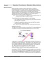
Digi One & PortServer TS Families
Digi One SP, Digi One IA, Digi One IAP, PortServer TS MEI Family, PortServer TS W MEI Family, PortServer TS 8/16,
PortServer TS 8/16 MEI, and PortServer TS 16 48V Dual Feed
visit www.digi.com
90000583_E
Digi International Inc. 2004. All Rights Reserved.
The Digi logo, Making Device Networking Easy logo, PortServer TS, Connectware, Digi One, and RealPort are
trademarks or registered trademarks of Digi International, Inc.
Contents
Chapter 1 Introduction
About This Guide................................................................................... 9
Purpose .............................................................................................................. 9
Audience............................................................................................................. 9
Scope ................................................................................................................. 9
Other Documents in the Library.............................................................9
Quick Start Guide ............................................................................................... 9
Digi Command Reference .................................................................................. 9
RealPort Setup Guides ....................................................................................... 9
AT Command Reference .................................................................................... 9
Online Help for the Web UI (User Interface)* ................................................... 10
Setup Overview ................................................................................... 10
Step A: Plan...................................................................................................... 10
Step B: Set Up the Hardware ........................................................................... 10
Step C: Install and Setup Digi Port Authority-Remote ...................................... 10
Step D: Configure an IP Address ..................................................................... 10
Step E: Configure Ports .................................................................................... 10
Step F: Configure Other Features as Required ................................................ 11
Supported Devices .............................................................................. 11
About Configuration Methods .............................................................. 11
Configure the Digi Device with the Wizard ....................................................... 11
Configure the Digi Device from an Attached Terminal ..................................... 11
Configure the Digi Device from a Telnet Session ............................................. 11
Configure the Digi Device from the Web Interface ........................................... 11
Downloading a Configuration File..................................................................... 12
Accessing the Configuration from the Web Interface ..........................12
Quick Find Feature Support Table ......................................................12
Chapter 2 Configuring the IP Address
Options for Configuring the IP Address and Mask .............................. 15
Configuring the IP Address with Wizard .............................................. 15
IP Address with Digi Port Authority-Remote........................................16
Assumptions ..................................................................................................... 16
Procedure ......................................................................................................... 16
Configuring the IP Address Using ARP-Ping....................................... 16
Assumptions ..................................................................................................... 16
Procedure ......................................................................................................... 16
Configuring an IP Address using DHCP and RARP............................ 17
About DHCP and RARP ................................................................................... 17
Procedure ......................................................................................................... 17
Accessing the Digi Device ................................................................... 17
Chapter 3 Configuration
Network Settings ................................................................................. 19
Advanced Network Settings ............................................................................. 20
Configuring the Serial Ports................................................................. 20
Contents
3
Port Profiles ......................................................................................... 23
RealPort............................................................................................................ 23
Console Management ...................................................................................... 23
TCP Sockets..................................................................................................... 24
UDP Sockets .................................................................................................... 24
Serial Bridging .................................................................................................. 25
Printer ............................................................................................................... 26
Terminal............................................................................................................ 26
Industrial Automation ........................................................................................ 27
Configuring Industrial Automation with Modbus ............................................... 27
Chat Mode ........................................................................................................ 28
Modem Profiles................................................................................................. 28
Modem Emulation............................................................................................. 29
Modem.............................................................................................................. 29
Internal Modem................................................................................................. 30
Power Management ......................................................................................... 30
Custom ............................................................................................................. 31
User Configuration............................................................................... 32
Common User Features ................................................................................... 33
User Access Method ........................................................................................ 34
Security Configuration .........................................................................34
Procedure ......................................................................................................... 35
System Configuration .......................................................................... 35
PPP Settings .................................................................................................... 35
SNMP ............................................................................................................... 37
MEI ................................................................................................................... 38
About Autoconnection .........................................................................38
Configuring a Port for Autoconnection................................................. 39
Configuring a User for Autoconnection................................................ 39
Chapter 4 IA Profiles and Procedures
In This Chapter .................................................................................... 41
Profiles................................................................................................. 41
Procedures .......................................................................................... 42
Key Terms in This Chapter.................................................................. 42
Serial Bridge: Master and Slave Connected to Digi Ports ................... 43
About This Profile ............................................................................................. 43
Configuration Options ....................................................................................... 43
Locating Setup Information: Slave Side ........................................................... 44
Locating Setup Information: Master Side ......................................................... 44
Modbus Profile: Serial-Connected Slave.............................................44
About This Profile ............................................................................................. 44
Configuration Options ....................................................................................... 44
Locating Setup Information............................................................................... 45
Modbus Profile: Serial-Connected Master........................................... 45
About This Profile ............................................................................................. 45
Configuration Options ....................................................................................... 45
Locating Setup Information............................................................................... 45
DF1 Profile: Serial-Connected Slave................................................... 46
About This Profile ............................................................................................. 46
Configuration Options ....................................................................................... 46
4
Contents
Locating Setup Information............................................................................... 46
DF1 Profile: Serial-Connected Master................................................. 46
About This Profile ............................................................................................. 46
Configuration Options ....................................................................................... 47
Locating Setup Information............................................................................... 47
Omron Family Profile: Serial-Connected Slave ................................... 47
About This Profile ............................................................................................. 47
Configuration Options ....................................................................................... 47
Locating Setup Information............................................................................... 47
Omron Family Profile: Serial-Connected Master ................................. 48
About This Profile ............................................................................................. 48
Configuration Options ....................................................................................... 48
Locating Setup Information............................................................................... 48
Other Serial Port Protocol Profile: Serial-Connected Slave.................48
About This Profile ............................................................................................. 48
Configuration Options ....................................................................................... 48
Locating Setup Information............................................................................... 49
Other Serial Port Protocol Profile: Serial-Connected Master............... 49
About This Profile ............................................................................................. 49
Configuration Options ....................................................................................... 49
Locating Setup Information............................................................................... 49
Configuring a Serial-Connected Slave: Generic Procedure ................ 49
About This Procedure ....................................................................................... 49
Procedure ......................................................................................................... 50
Configuring a Serial-Connected Master: Generic Procedure .............. 50
About This Procedure ....................................................................................... 50
Procedure ......................................................................................................... 50
Configuring a Serial-Connected Master: TCP/UDP Sockets............... 50
About This Procedure ....................................................................................... 50
Procedure ......................................................................................................... 50
Configuring a Serial-Connected Slave: Other IA Protocol................... 51
About This Procedure ....................................................................................... 51
Procedure ......................................................................................................... 51
Configuring a Serial-Connected Master: Other IA Protocol.................51
About This Procedure ....................................................................................... 51
Procedure ......................................................................................................... 51
Setting Up COM Port Redirection........................................................ 52
About These Procedures .................................................................................. 52
Setup Tasks: An Overview ............................................................................... 52
Procedure: Configuring the Serial Port for RealPort......................................... 53
Enabling Pass-Through Port ............................................................... 53
About these procedures ................................................................................... 53
Procedure: Enabling the pass-through port ...................................................... 53
Running Diagnostics......................................................................................... 53
Updating POST Code.......................................................................... 54
Prerequisite ...................................................................................................... 54
Procedure ......................................................................................................... 54
RealPort Decision Guide ..................................................................... 56
Chapter 5 Special Features: Wireless
Configuration Considerations .............................................................. 57
Contents
5
Initial Configuration Using Ethernet .................................................................. 57
Chapter 6 Special Features: Software Selectable MEI
About MEI Settings.............................................................................. 61
Configure the MEI Switches ................................................................ 61
Table for Pin Outs............................................................................................. 62
Set the Supported Baud Rate for Multi-drop Support ....................................... 63
Four-Wire Multi-Drop Network Scenarios............................................ 63
MEI Configuration for a Single Master:............................................................. 63
MEI Configuration for a Slave:.......................................................................... 64
Chapter 7 Special Features: Embedded Modem
Embedded Modem .............................................................................. 65
Installing the PortServer TS 1/3 M MEI ............................................................ 65
Configuring the PortServer TS 1/3 M MEI ........................................................ 65
Chapter 8 Special Features: Modem Emulation
Modem Emulation................................................................................ 67
Common User Scenarios ................................................................................. 67
Modem Emulation Cable Signals ........................................................ 68
Scenarios for Modem Emulation ......................................................... 68
Outgoing Modem Emulation Connection .......................................................... 68
Incoming Modem Emulation Connection .......................................................... 69
Modem Emulation Pooling................................................................................ 69
Modem Emulation Bridge ................................................................................. 69
Originating, Answering, and Disconnecting Calls................................ 69
Disconnecting Calls-Digi Device....................................................................... 70
Modem Emulation AT Command Set .................................................. 70
S-Registers.......................................................................................... 76
Result Codes .......................................................................................81
Chapter 9 Special Features: Power Over the Serial Ports
Serial Power Feature........................................................................... 83
Configuring RI Power .......................................................................... 83
RI Power In....................................................................................................... 83
RI Power Out .................................................................................................... 84
Configuring DTR Power....................................................................... 84
Power Out......................................................................................................... 84
Serial Power Table .............................................................................. 85
Chapter 10 Special Features: SNMP
About SNMP and the Digi Device Agent .............................................87
Network Management Components ................................................................. 87
SNMP Management Agent ............................................................................... 87
SNMP Traps ..................................................................................................... 87
MIB Support...................................................................................................... 87
Message Support ............................................................................................. 88
Supported Traps ............................................................................................... 88
Configuration Procedure: Web Interface .............................................88
6
Contents
Chapter 11 Configuration Management
Upgrading the Firmware ...................................................................... 89
TFTP Upgrade Procedure ................................................................................ 89
Copying the Configuration to and from a Remote Host....................... 89
When To Use Remote Configuration................................................................ 89
Download Procedure ........................................................................................ 89
TFTP Procedure for Backup or Restore ........................................................... 90
Resetting Configuration to Defaults..................................................... 90
Chapter 12 Reference and Certifications
Interpreting the LEDs........................................................................... 91
LEDs ................................................................................................................. 91
PortServer TS 8/16 LEDs ................................................................................. 92
Device EIA 232/422/485 Switch Settings ......................................................... 92
RJ-45 Pinouts ................................................................................................... 93
Safety Statements ............................................................................... 93
PortServer TS 8/16 and PortServer TS 16 48V Dual Feed .............................. 93
Rack Mounting Installation Considerations (PortServer TS 16 Rack and DC Rack
and PortServer TS 16 48V Dual Feed)............................................................. 93
PortServer TS 1/3 M MEI ................................................................................. 94
Specifications ...................................................................................... 95
Power Requirements ........................................................................................ 95
Physical Requirements ..................................................................................... 96
Digi One IA DB9 and Screw Terminal Pinouts ................................................. 97
PortServer TS 1/3 M MEI ................................................................................. 97
FCC Class A Statement ...................................................................... 97
Digi One SP, Digi One IA, Digi One IAP, PortServer TS 8, PortServer TS 8 MEI,
PortServer TS 16 MEI, PortServer TS 16 48V Dual Feed................................ 97
Regulatory Notices .............................................................................. 98
Certifications........................................................................................ 98
FCC Part 15 Class A (Digi One IA, Digi One IAP, Digi One SP, PortServer TS 8,
PortServer TS 8 MEI, PortServer TS 16 MEI) .................................................. 98
Radio Frequency Interference (RFI) (FCC 15.105) .......................................... 98
Labeling Requirements (FCC 15.19) ................................................................ 99
Modifications (FCC 15.21) ................................................................................ 99
Cables (FCC 15.27).......................................................................................... 99
ICES 003 Class B ( PortServer TS 1 MEI, PortServer TS 1 W MEI, PortServer TS
2/4 MEI, PortServer TS 2/4 W MEI, PortServer TS 16).................................... 99
Antennae (Wireless only) ................................................................................. 99
Maximum Permissible Exposure (Wireless only) ............................................. 99
Declaration of Conformity ................................................................................. 99
Digi Contact Information .................................................................... 100
Contents
7
8
Contents
Introduction
Chapter 1
About This Guide
Purpose
This user guide provides the following:
• Configuration and administration procedures
• Configuration examples
Audience
This guide is intended for the person responsible for configuring and
administering the Digi device. It assumes that this person has experience
configuring network devices and is familiar with networking concepts.
Scope
This guide provides step-by-step instructions for configuring and
administering your Digi device’s main features. It focuses on performing
these tasks through the Web user interface. It does not address how to
configure every option, provide complete information on commands, or
discuss hardware installation. These topics are covered in other
documents in the Digi library.
Other Documents in the Library
The Digi library is a collection of documents found on the Software and
Documentation CD under Documentation. The following is a description of
the documents available on the CD.
Quick Start Guide
The guide that comes in the package with the Digi device covering the first
steps necessary to get your device up and running. UNIX mounting
instructions can be found on the back of the Quick Start Guide.
Digi Command Reference
This online manual, available on the Software and Documentation CD,
provides complete information on commands.
Cable Guide
This manual provides cabling information for connecting your peripheral
devices to the Digi device.
RealPort Setup Guides
These online manuals provide information on setting up servers for and
installing the RealPort software.
AT Command Reference
The complete reference for all the AT commands for the embedded
modem products (PortServer TS 1 M MEI and PortServer TS 3 M MEI).
Note:
Chapter 1
Introduction
The Modem Emulation feature described later in this document has its own
set of AT commands that are listed in the "Modem Emulation AT Command
Set" on page 70.
9
Online Help for the Web UI (User Interface)*
This context-sensitive online help provides information on configuration
fields used with web browser configuration interface.
*This information is part of the user interface and not an actual document
on the CD.
Setup Overview
The Following is an overview of the process for setting up a device in the
Digi TS family. The rest of this guide provides details on each step of the
process.
Step A: Plan
Before beginning setup, consider the following:
• How to assign an IP address to the Digi device’s Ethernet interface,
which can be accomplished in a number of ways. See "Configuring
the IP Address" on page 15.
• The various ways in which your Digi device can be configured. See
"About Configuration Methods" on page 11 for more information.
Note:
A key consideration is whether to use RealPort. Other considerations include
the type of peripheral that will connect to the port and the peripheral’s cabling
requirements. See "RealPort Decision Guide" on page 56 and the online
RealPort driver documentation and Cable Guide, both of which are on the
Software and Documentation CD.
Step B: Set Up the Hardware
1. If the Digi device supports multiple serial port interfaces (EIA-232,
EIA-422/485), set the interface with the dip switches on the device.
2. Connect peripherals to serial ports. See the Cable Guide on the
Software and Documentation CD.
3. Connect the device to the network.
4. Connect the power supply to the Digi device.
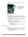
Step C: Install and Setup Digi Port Authority-Remote
Digi Port Authority-Remote is a utility that provides one of the ways to
configure an IP address and also provides port monitoring.
Step D: Configure an IP Address
There are a number of ways to configure an IP address. See "Configuring
the IP Address" on page 15 for more information.
Step E: Configure Ports
See the following for more information:
• "IA Profiles and Procedures" on page 41
• "Network Settings" on page 19
10
Chapter 1 Introduction
Step F: Configure Other Features as Required
See the following for information on setting up other features:
• "Security Configuration" on page 34
• "PPP Settings" on page 35
• "About Autoconnection" on page 38
Supported Devices
This manual provides information on the following Digi devices:
• Digi One IA and Digi One SP
• Digi One IAP
• PortServer TS 1/2/4 MEI, PortServer TS 1/2/4 H MEI, and
PortServer TS 1/2/4 W MEI
• PortServer TS 1/3 M MEI
• PortServer TS 8/16, PortServer TS 16 Rack, PortServer TS 16 DC
Rack, PortServer TS 8/16 MEI, PortServer TS 16 48V Dual Feed
About Configuration Methods
Use this section to learn about the different configuration methods.
Configure the Digi Device with the Wizard
Simply follow the prompts and choose your configuration with the wizard
available on the CD. Choose either a Microsoft Windows or UNIX platform.
The wizard will configure your device based on your description of your
environment and determine (for you) if you need to install RealPort. This is
the recommended and preferred method for configuration.
Configure the Digi Device from an Attached Terminal
With this method, you cable a terminal or PC running terminal emulation
software to a device server port and then use the command line to enter
commands. This method allows you to configure all features. It requires,
however, that you and the device server be in the same location. Some
users find it advantageous to configure the device server IP address this
way and then use one of the other methods for the rest of the configuration.
Configure the Digi Device from a Telnet Session
With this method, you Telnet to the device server and use the command
line to complete configuration tasks. The only disadvantage to this method
is that you have to configure the device server with an IP address before
you can Telnet to it.
Configure the Digi Device from the Web Interface
The great advantage to this method is ease of use. This method requires
that you configure the IP address before you can access the configuration
from the web interface, however, some features cannot be configured this
way.
Chapter 1
Introduction
11
Downloading a Configuration File
With this method, you configure a Digi device and then do the following:
1. Download an existing configuration file to a host system.
2. Edit the file with specific configuration using a text editor.
3. Upload the file to the device server.
This an excellent method for maintaining highly similar configuration files
for multiple Digi devices. The disadvantage is that the device server
requires some configuration steps, such as the IP address, to be
completed before it can be used.
Accessing the Configuration from the Web Interface
To access the configuration from the web interface, follow these steps.
This procedure assumes that you have configured the Digi device with an
IP address already. See "Configuring the IP Address" on page 15.
1. Access the Digi device from a web browser by specifying the device
server’s IP address in the URL window.
2. Log on as root. The default password is dbps.
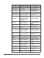
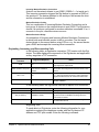
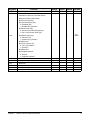
Quick Find Feature Support Table
The following table is a quick reference for specific features and where to
find the web interface configuration procedures. The User’s Guide supports
the following products:
• Digi One IA
• Digi One SP
• Digi TS Family -The Digi TS Family includes the following devices:
— Digi One IAP
— PortServer TS 1 MEI
— PortServer TS 2 MEI
— PortServer TS 4 MEI
— PortServer TS 1 H MEI
— PortServer TS 2 H MEI
— PortServer TS 4 H MEI
— PortServer TS 1 W MEI
— PortServer TS 2 W MEI
— PortServer TS 4 W MEI
— PortServer TS 1 M MEI
— PortServer TS 3 M MEI
— PortServer TS 8
— PortServer TS 16 (and Rack models)
— PortServer TS 8 MEI
— PortServer TS 16 MEI
12
Chapter 1 Introduction
Feature
Chapter 1
Introduction
Digi Devices Supported
Configuration
Overview
Access Control
Digi TS Family
User > New User >
determine access
AutoConnection
Digi TS Family
Serial Port > Port Profile
>TCP Sockets
DNS
Digi TS Family
System > System Name
Embedded Modem
PortServer TS 1 M MEI
PortServer TS 3 M MEI
Serial Port > Port Profile >
Internal Modem
Industrial
Automation (IA)
Digi TS Family*
The TS Family supports the IA
port profile but only the
PortServer TS 1/2/4 MEI
support Modbus RTU and
Modbus ASCII.
Serial Port > Port Profile
>Industrial Automation
IP Routing
PortServer TS 8/16,
PortServer TS 8/16 MEI
Serial Port > Port Profile > IA
> Serial Master > Packet
Routing
Modem Emulation
All devices supported
Serial Port > Port Profile >
Modem Emulation
Pass-thru Port
Digi One IAP
Enable Pass-thru switch on
case and reboot
Power Management
PortServer TS 2/4 MEI
PortServer TS 2/4 W MEI
PortServer TS 8/16
Serial Port > Port Profile
>Power Management
Power Over Serial
Port
PortServer TS 1/2/4 W MEI
PortServer TS 2/4 MEI
See "Special Features:
Power Over the Serial Ports"
on page 83
PPP
Digi TS Family
System > PPP
RADIUS
PortServer TS 8/16,
PortServer TS 8/16 MEI
Security > RADIUS
RealPort
All devices supported
Serial Port > Port Profile >
RealPort
Software Selectable
MEI
PortServer TS 8/16 MEI
Serial Port > MEI Serial
Settings
SSH Version 2
PortServer TS 2/4 MEI
PortServer TS 8/16
Secruity > Network Security
> Custom
TCP Socket
Communication
All devices supported
Serial Port > Port Profile
>TCP Sockets
UDP Multicast
Communication
All devices supported
Serial Port > Port Profile
>UDP Sockets
Wireless
PortServer TS 1/2/4 W MEI
Network > Wireless LAN
Settings
13
14
Chapter 1 Introduction
Configuring the IP Address
Chapter 2
The next step in the device configuration process is to configure an IP
address and access the device for more advanced configurations. You
must set the initial IP before you can use the web interface. Once the IP is
set, the device can be accessed through the web interface and any
changes made including changing the IP address.
Options for Configuring the IP Address and Mask
The device server IP address can be configured using the following
methods:
• With the Wizard from the Software and Documentation CD. (Insert
the Software and Documentation CD and the wizard automatically
pops up letting you choose Microsoft Windows platform or UNIX
platform. If you have a UNIX system and the wizard does not pop
up, see the back of the quick start guide for mounting instructions.)
• With Digi Port Authority-Remote, a Digi utility on the Software and
Documentation CD. See "IP Address with Digi Port AuthorityRemote" on page 16.
• From the command line, using the set config command. See the
Digi Command Reference for more details including syntax and
supported devices.
• By updating the ARP table on a server and then pinging the Digi
device (called ARP-Ping, see "Configuring the IP Address Using
ARP-Ping" on page 16).
• Using a DHCP server ("Configuring an IP Address using DHCP and
RARP" on page 17.)
• Using a RARP server ("Configuring an IP Address using DHCP and
RARP" on page 17.)
The IP address and mask can also be changed using the web interface,
but not for initial IP address configuration.
Configuring the IP Address with Wizard
Configure the IP Address with the wizard found on the Software and
Documentation CD. The wizard is the preferred method for configuring the
Digi device and available in both Microsoft Windows platform and UNIX
platform. If you have a UNIX platform without auto-mount, use the back of
the Quick Start guide for mounting instructions.
1. Insert the CD (the wizard automatically pops up)
2. Select your platform.
3. Follow the wizard by answering the prompts. When the wizard is
complete, you will be prompted to run the RealPort software (if your
configuration calls for it.) Follow the prompts for complete installation.
Chapter 2
Configuring the IP Address
15
IP Address with Digi Port Authority-Remote
Use this section to configure an initial IP address, subnet mask, and default
gateway using Digi Port Authority-Remote. This procedure cannot be used
to change the IP address, but only to assign the initial IP address. It also
cannot be used if a DHCP server is active.
Assumptions
This procedure assumes the following:
• That your Digi device is connected to the Ethernet network.
• That the Digi device has DHCP client turned on. This is the default
setting and it will be on unless it was turned off.
• That you do not have a DHCP server to serve IP address. If you do,
use the DHCP procedure. See "Configuring an IP Address using
DHCP and RARP" on page 17.
• That you have installed Digi Port Authority-Remote version 2.01.11
or later and it is on the same subnet as the Digi device.
Note:
Click the Help button on the tool bar in Digi Port Authority-Remote to check
the version number.
Procedure
1. Run Digi Port Authority-Remote.
2. Click Discover. A list of Digi devices appears. Systems with IP
addresses of 0.0.0.0 need IP addresses.
3. Select a device from the list and then click Configure.
4. Supply an IP address, subnet mask, and default gateway and then
choose OK.
Digi Port Authority-Remote configures the IP address, subnet mask,
and default gateway.
Configuring the IP Address Using ARP-Ping
An IP address can be configured by manually updating a server’s ARP
table and then pinging the Digi device.
Note:
The ARP-Ping command assigns the IP address you designate but also
assigns default subnet mask and gateway addresses. It is necessary to
change the subnet mask and gateway addresses.
Assumptions
This procedure assumes that your Digi device is connected to the Ethernet
network
Procedure
1. Record the MAC address of the Digi device. The MAC address is on the
label side of the unit.
2. Access a server on the same subnet as the Digi device.
3. Manually update the server’s ARP table using the Digi device’s MAC
address and the IP address you want assigned to the Digi device. The
16
Chapter 2 Configuring the IP Address
following is an example of how this is done on a Windows NT 4.0
system:
arp -s 191.168.2.2 00-00-9d-22-23-60
4. Ping the Digi device using the IP address just assigned. The following is
an example:
ping 191.168.2.2
The ping will probably time out before there is a response from the Digi
device.
5. Wait 30 seconds and then ping the Digi device again.
The Digi device replies to the ping, indicating that the IP address has
been configured.
Configuring an IP Address using DHCP and RARP
About DHCP and RARP
When the device server boots, it transmits a DHCP request and a RARP
request. This continues until an address is assigned.
Procedure
To use RARP or DHCP follow these steps:
1. Set up an entry for an address on a DHCP or RARP server. If you
intend to use RealPort, do the following:
• Reserve a permanent IP address.
•
Record the IP address. You will need it when you configure the
RealPort driver.
2. Power on the device server.
The DHCP or RARP server assigns the device server an IP address.
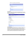
Accessing the Digi Device
1. Enter the IP address in the URL bar of your browser.
2. Enter your login name (root) and password (dbps).
Note:
Chapter 2
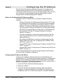
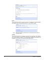
The following screen appears allowing you to configure the device for your
specific needs. A tutorial is available to guide you in your decisions. The Help
Configuring the IP Address
17
button in the upper right corner is also available.
From the web interface, you make any changes you need for your
configuration. Remember to click Apply to save your changes and Reboot
when you are ready for the changes to take effect.
18
Chapter 2 Configuring the IP Address
Configuration
Chapter 3
The next step in the device setup process is to configure the network and
serial port settings. In order to access the web interface an IP address
must be assigned. It is assumed you have logged onto the web interface
using the username, root and password, dbps in order to make any
changes or additional configuration assignments. However, it is important
to note that if you have used the wizard, your configuration is complete and
you do not need additional changes.
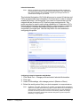
Network Settings
1. Click Network to view the IP settings or make any changes to the IP
address.
2. Enter the IP address for the DNS server in the Name Server box. The
DNS server maps names ( example: MyDeviceName.mycompany.com)
to IP addresses (example:192.105.1.2).
3. Enter the domain name that this device will live in that is tied to the DNS
server address assigned in step 2. This name can be used by other
network devices to talk to it, instead of using the its IP address. Get this
name from the network administrator, because it must be entered in the
DNS server to work properly.
4. Enter a host name for a group of network devices.
5. Enter the Base Socket. The base socket is the network which remote
devices need to use to access the device using the named protocols
such as, Telnet, TCP, or UDP.
Note:
Chapter 3
Configuration
Base Socket
This determines which network port (socket) on this Digi terminal server
another network device (such as another Digi terminal server or a PC) uses to
communicate using certain services. Most applications can leave this value
unchanged. To calculate these settings:
19
Telnet port = Base Socket + Serial Port Number
Raw port = Base Socket + 100 + Serial Port Number
Service
telnet
raw (TCP or UDP)
Base Socket
2000
2000
Network Port
2001
2101
6. Click Apply.
7. Click Reboot for changes to take effect.
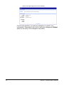
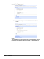
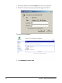
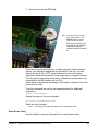
Advanced Network Settings
WARNING!!!!! changing the Advanced Network Settings could cause you to ‘lose’ your device
on the Network. If you alter these settings - you may need to reset your device with the reset
button and reconfigure your device as if it were new. See "Resetting Configuration to Defaults"
on page 90 for instructions.
****The next screen shot is for informational purposes. Digi
International recommends that you do NOT alter the Advanced Network
Settings. Be advised these settings are correct for most environments.
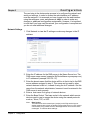
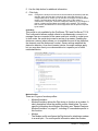
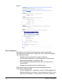
Configuring the Serial Ports
1. Click Serial Ports under Configuration.
20
Chapter 3 Configuration
2. Click the port number that you want to configure.
3. Click Change Profile and select a profile based on the device you have
connected to your port.
Note:
Chapter 3
Configuration
If this is the first profile assigned or if the unit has been restored to factory
defaults, the interface will take you directly to the port profile page. The
following section shows the settings available for each profile.
21
Note:
The ‘More’ link will describe the profiles with additional information.
Note:
Profiles are available based on the features supported by your device.
Naturally, if you do not have a device capable of a specific profile such as
Power Management or Wireless, you will not see that particular profile. Check
the "Quick Find Feature Support Table" on page 12 to verify if your device
supports a particular feature.
4. Click Apply to save the profile. The interface will determine any
additional settings and port options page will come up and ask for
additional parameters if needed. See "Port Profiles" on page 23 or click
Help for additional information.
5. Enter the appropriate parameters and click Apply.
6. Click Reboot for changes to take effect.
22
Chapter 3 Configuration
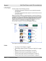
Port Profiles
Each port profile determines the settings needed. The following
screenshots of each profile show the port settings. For a complete
description of each profile click the Help button.
RealPort
Installed on a network-based PC, RealPort emulates a serial port. That is,
the application “thinks” it is working with a real serial port, such as COM1.
When the application sends data to this serial port, RealPort encapsulates
the data and ships it across the network to the Digi device which in turn
routes it to the serial device. This is also referred to as COM Port
Redirection. The network is transparent to both the application and the
device.
Console Management
Access a device's console port over a network connection. Most network
devices such as routers, switches, and servers offer serial port(s) for
management. Instead of connecting a terminal to the console port, cable
the console port to the serial port of your Digi device. Then using Telnet
features, network administrators can access these consoled serial ports
from the LAN by addressing the appropriate TCP port.
Under Console Management you may also enable port sharing. Port
sharing allows up to 4 users to access the same port at the same time. If
port sharing is disabled, then only one user may access the port at a time.
IYou may change the number of users at any time. If you increase the
number of users from 2, the change takes effect immediatly. If you
decrease the number of users, the change does not take effect until the
users log off. (for example if port sharing is available for 4 with 4 users on,
then changed to 2, the change will not take effect until at least 2 users log
Chapter 3
Configuration
23
off. If port sharing is enabled for 2 and then disabled, the change will not
take effect until everyone is off. The default value when port sharing is
disabled is one.
TCP Sockets
The Digi One IA/SP and the Digi TS Family devices support TCP socket
communication. TCP socket communication enables serial devices to
communicate with each other over an Ethernet network as though they
were connected by a serial cable.
Configuring TCP socket communications involves configuring the Digi
device for the following types of connections:
• Inbound connections, that is, connections that are initiated by the
device on the other side of the network.
• Outbound connection, that is, connections that are initiated by the
device connected to the serial port.
Note:
TCP Sockets profile is also the profile to use for Autoconnection. See "About
Autoconnection" on page 38 for more information.
UDP Sockets
The Digi One IA/SP and the Digi TS Family devices are capable of UDP
multicast. UDP multicast is used to send serial data over an Ethernet cable
to one or many hosts at the same time. UDP does not need a protocol
because it sends data without any form of acknowledgment of error or error
correction. Up to 64 devices can receive a UDP multicast at one time. Both
the transmitting and receiving devices must be configured properly for UDP
multicast to work.
Configuring UDP multicast communications involves configuring the Digi
device for the following types of connections:
• Inbound connections, that is, connections that are initiated by the
device on the other side of the network.
• Outbound connections, that is, connections that are initiated by the
device connected to the serial port.
24
Chapter 3 Configuration
Note:
The serial parameters for two connecting devices must match meaning if one
device is set for 9600 bps, the other device must be set for the same rate.
Serial Bridging
The Digi One IA/SP and the Digi TS Family devices support serial bridging
(sometimes referred to as ‘tunneling’). A serial bridge is a network
connection between two serial devices, each of which uses a device
server. The serial devices “think” they are communicating with each other
across a serial cable using serial communication techniques. There is no
need to reconfigure the server or the serial device. Neither is aware of the
intervening network.
This profile configures each side of the bridge separately. Repeat the
configuration for the second Digi device using the web interface. Enter the
IP address in the URL bar of your browser and follow the same procedure
of the bridge specifying the IP address of the first Digi device.
Chapter 3
Configuration
25
Printer
This profile allows you to connect a printer to a serial port. Use this profile if
you intend to print using the lpd protocol on your UNIX system.
Note:
Refer to your UNIX User Guide for tips on configuring the print spooler on
your UNIX system.
Terminal
This profile allows you to connect a terminal to the serial port. Also allows
you to automatically establish TCP connections, enabling the connection to
a system or a device on the network when data arrives.
26
Chapter 3 Configuration
Industrial Automation
Note:
Before you decide you use the Industrial Automation profile consider the
recommended IA Wizard. (Select Industrial Automation under Applications
then click IA Wizard.) The IA Wizard will guide you through common IA
scenarios and configure your device.
The Industrial Automation (IA) Profile allows you to connect IA devices and
PLCs (programmable logic controller) to the serial port in order to networkenable the devices. Use this profile if you need to communicate over the
network with an IA device or PLC that only uses serial protocols. This
profile may also be used to add routing capabilities to IA devices or PLCs
that act as serial masters and send packets to various systems or devices
on the network. Industrial Automation enhances the IA device or PLC
connected to the serial port. Use the Help button for more assistance
configuring this profile.
Configuring Industrial Automation with Modbus
1.
2.
3.
4.
Click Serial Port > Change profile and select Industrial Automation.
Click Apply.
Under Profile settings, click change protocol -(Master or Slave).
Select the serial protocol that your device expects to communicate on.
Note:
PortServer TS 1 MEI, PortServer TS 2/4 MEI use Modbus RTU and Modbus
ASCII. For all other devices the only option is User defined.The User Defined IA
serial protocol is useful for devices or PLC’s that do not use any of the predefined
protocols and have a protocol that conforms to the following criteria: All message
packets are bounded by fixed header and trailer strings Every protocol request is
followed by a single response.
Chapter 3
Configuration
27
5. Use the Help button for additonal information.
6. Click Apply.
Note:
Configure the serial port for the serial communication parameters (baud rate,
data bits, parity and stop bits) required by the connected IA device. If you
configure the port for a slave, you do not have to configure a network-based
master. Communication with the master just works. (If the master is
connected to a serial port, it must be configured, however.) If you configure a
port for a master and the slaves are located on the network, TCP sockets,
UDP sockets, and Modbus/TCP are all supported. Use the protocol required
by the master.
Chat Mode
This profile is only available for the PortServer TS 8 and PortServer TS 16.
This configuration allows multiple clients to simultaneously connect to or
manage a server connected to the same serial port -similar to a chat room.
In chat mode, the serial device can be a slave or a master. Enabling the
device as a server (slave) allows you to establish the end of line detection,
the timeouts, and the disconnect conduct. Server settings establish the
data echo direction. As a client (master) device, the same settings apply
but you may also direct your communication to a specific port or other
networked device.
Modem Profiles
There are 3 types of modem profiles:
• Modem Emulation
Modem Emulation allows the Digi device to function as a modem. A
short description follow the modem profiles listed below. For more
specific information about Modem Emulation see "Special Features:
Modem Emulation" on page 67, including AT commands specific to
this function.
• Modem
The Modem profile configures the Digi device for attaching a modem
to a serial port. For more specific information about the modem
28
Chapter 3 Configuration
•
profile use the Help button in the upper right corner on the profile
page of the web interface.
Internal Modem
The Internal Modem profile (not listed in the graphic) is specific to
the PortServer TS 1/3 M MEI devices. The fully functioning modem
is embedded in port one and uses the standard AT command set.
See the Documentation on the Digi CD for the complete AT
Command Reference.
Modem Emulation
Modem Emulation allows you to configure the serial port to act as a
modem. The Digi device emulates modem responses to a serial device
and seamlessly sends and receives data over an Ethernet network instead
of a PSTN (Public Switched Telephone Network). The advantage for a user
is the ability to retain legacy software applications without modification and
use a less expensive Ethernet network in place of public telephone lines.
Modem
Modem allows you to attach modem devices to the serial port in order to
establish or receive connections from other systems and modems.
Note:
Chapter 3
Configuration
Select Enable PPP Connections on this Modem and click the PPP
Configuration link to set up incoming, outgoing or advanced PPP settings if
the attached modem uses PPP connections. See "System Configuration" on
29
page 35 for more information about PPP settings.
.
Internal Modem
Used for the serial ports that contains the embedded modem. This profile
allows you to configure the modem port. This profile configures the internal
modem for PPP connections.
Power Management
The Power Management feature allows you to connect the serial port to a
power controller. The Digi device will monitor the power controller to
provide the status and control of power outlets. This feature is used most
commonly in a console management application, where the console port of
a server is connected to one serial port of the Digi device for remote
access, and the AC power plug of the server is connected to a power
30
Chapter 3 Configuration
controller for AC power control.
Note:
Power controller settings can be automatically detected or configured
manually.
Custom
This profile allows you to see all settings and set them accordingly. Use this
profile only if your application does not fit into any of the predefined port
Chapter 3
Configuration
31
profiles.
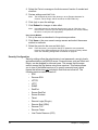
User Configuration
Although it is not required, the device server is often configured to
accommodate the requirements of particular users. Typical configurable
user attributes include:
• Whether the user is required to supply a password.
• Autoconnection attributes, such as the system to which the user
should be automatically connected at login.
• The interface the device presents the user, such as a menu or
command line.
• Whether the user has access to outbound ports.
Users select a user profile that most closely describes the user’s
environment. Profiles include:
• Console Management - expected to connect to and manage serial
devices that have a console port. Users can connect directly, use a
custom menu interface, or reverse telnet or SSH into a serial port.
32
Chapter 3 Configuration
•
Terminal/Terminal Emulation -using a terminal or terminal emulation
program to connect to the serial port and needs to automatically
connect to a device available on the network.
•
Custom - using a terminal or terminal emulation program to connect
to the serial port and needs to automatically connect to a device
available on the network.
Note:
For information on configuring PPP users, see "PPP Settings" on page 35.
Common User Features
Feature
Description
autoconnect
Automatically connects the user to the host specified on the autohost
field using the service (TCP port) defined on the autoport or
autoservice fields.
Autoconnection can also be implemented by port instead of by user.
Default
access type
Defines the type of access the user is restricted to. Menu, command
line, autoconnect, and outgoing and netservice are the types.
Menu
access
Defines the menu that is to be presented to a user with menu
access.
Port access
Defines the number of outbound ports a user connected over the
LAN can access at one time.
This feature is not configurable from the web interface.
PPP
Defines PPP-related parameters for the user.
Routing
updates
Defines whether RIP routing updates are forwarded over the link to
this user.
1. Click Users > New User
2. Enter the Username, password, and password confirmation and click
Next.
3. Select the profile that fits the user’s environment/needs and click Next.
Chapter 3
Configuration
33
4. Select the Ports to manage or the Autoconnect function if needed and
click Next.
5. Review settings and click Finish.
Note:
The Advanced tab under User allows you to set Escape characters for
Connect, Telnet, Rlogin, and Kill as well as an SSH Public Key.
6. Click Apply to save the settings.
7. Click Reboot for changes to take effect.
Note:
User attributes can be changed after the user is set up. Click User > the
User’s name. From here you can change the password, the access method,
the menu, or verify the user’s properties.
User Access Method
1. Set up the user as described in the previous procedure.
2. Click Users > the user name to assign access and select the access
method or methods.
3. Select the ports for the user and click Apply.
Note:
From this screen, you may also change or update the users password.
However, if the Admin password is lost, the only recovery is factory default
reset. See "Resetting Configuration to Defaults" on page 90.
Security Configuration
Security settings allow the administrator to set passwords, security levels,
and authentication via RADIUS server. Some services, such as Telnet and
Rlogin, can be disabled for inbound users. This means that the users
cannot access the Digi device using those services. This feature allows
you to turn off individual services or to specify a security level, which
means that all services not included in that level are turned off. The
following services can be turned off.
• SSH
• Reverse SSH
• HTTPS
• HTTP
• SNMP
• RealPort
• Secure RealPort
• Secure Sockets
• Telnet
• Remote Login (RLogin)
• Remote Shell (RSH)
• Reverse TCP
• Reverse Telnet
• Line Printer Daemon (LPD)
34
Chapter 3 Configuration
Procedure
1. Click Security > and enter a new password for the root administrator.
2. Enter the confirmation password and click Apply.
3. Click Network Security and select the security level appropriate to your
environment and click Apply.
Note:
Secure Access Levels Secure: SSH is the only service available to inbound users.
High: SSH, HTTP, SNMP, and RealPort services are available to inbound
users.
Normal: all services are available.
Custom, which means you can select services to turn off.
The default service level is Normal.
4. Click RADIUS and select Authenticate users via RADIUS server.
Note:
If you do not have RADIUS available, Click Apply and then Reboot
5. Enter the Primary server’s IP address and Primary server’s secret and
click Apply.
Note:
The Primary server’s secret is the password used for encryption of messages
between the RADIUS server and the Digi device.
6. Click Reboot for changes to take effect.
System Configuration
System settings allow you to tune the performance optimizing throughput
or latency, the date and time, PPP connections, SNMP traps, and Baud
rates for MEI.
1. Click System and enter the System Description (network name
assigned to the Digi device), Contact (SNMP contact person -often the
network administrator), Location (text description of the physical
location of the Digi device), and Optimization (bandwidth used on the
network) and click Apply
Note:
Latency - Allows fast access to time-sensitive devices. Requires more
network bandwidth.
Throughput - Allows better network performance at higher throughput.
2. Click Date/Time
Note:
If you do not have Date/Time available, Click Reboot
3. Enter the date and time information and click Apply.
4. Click Reboot for changes to take effect.
PPP Settings
Under System Configuration, users can set the PPP (Point-to-Point
Protocol) options to enable or disable the dynamic IP address pool. The
dynamic IP address pool is a set of reserved IP addresses unique to the
network that are assigned to the incoming connections. Users set the first
IP address to use and the number of sequential addresses (plus one) to be
reserved for assignment.
1. Click PPP.
Chapter 3
Configuration
35
2. If you are using PPP select Enable Dynamic IP Address Pool for
Incoming Connections.
3. Enter the first reserved IP address of the incoming connections and the
number of addresses to use and click Apply.
4. Click Incoming Connections > New Connection
5. Enter the appropriate parameters and click Apply.
6. Click Reboot for changes to take effect.
For outgoing connections, CHAP or PAP authentication, or password
configuration, use the following procedure.
1. Click Outgoing Connections
Note:
CHAP authentication can be used to restrict PPP user access to outbound
ports.
2. Enter the appropriate parameters and click Apply.
36
Chapter 3 Configuration
3. Click Reboot for changes to take effect.
For dynamic routing or proxy ARP settings follow the procedure for
Advanced PPP settings.
4. Click Advanced PPP settings.
Note:
5.
6.
7.
8.
9.
Use the Help button for more information about configuring Advanced PPP
settings.
Select Enable Dynamic Routing (RIPv1)
Select the passive or active route setting.
Select the Process ARP requests if appropriate.
Click Apply.
Click Reboot for changes to take effect.
SNMP
1. Click System > SNMP
2. Select Enable SNMP.
3. Enter the community (public or private)
Chapter 3
Configuration
37
4. Select the type or types of traps you wish to enable.
5. Click Apply.
MEI
This setting only applies to EIA-422/485 Half-Duplex (2 wire) ports. For
more information see "Special Features: Software Selectable MEI" on page
61.
1. Select System > MEI.
2. Select Baud rate from the drop down box.
3. Select apply to all ports if appropriate.
4. Click Apply for configuration to take effect.
About Autoconnection
The autoconnection feature allows you to configure a user to access the
device server and then be automatically connected to a host on the LAN.
You can implement autoconnection in the following ways:
38
Chapter 3 Configuration
•
•
By port, where all port users are automatically connected to the
same host. The device server is completely transparent to them.
By user, where a user is required to log on and may be required to
supply a password. Once the user is authenticated, an automatic
connection to a host is made.
Configuring a Port for Autoconnection
1. Select Serial Ports under Configuration.
2. Click the TCP Sockets Port Profile.
Note:
TCP Sockets is the Autoconnection profile.
3. Click Apply.
4. Select Automatically establish TCP connections and the appropriate
parameters. Use the Help button for addtional information.
5. Click Apply.
6. Click Reboot for changes to take effect.
Note:
To return to the main Ports menu, choose Ports from the Menu again.
Configuring a User for Autoconnection
1. Click Users from the menu.
2. Choose New User.
3. Enter a username and then click Next.
4. Select the “Terminal/Terminal Emulation” user profile and click Next
5. Select Automatically connect to a ...
Be sure to specify the following:
• Hostname or IP address that will be the destination
• Service
• Destination TCP port number, which determines the type of
connection for this user (such as 23 for Telnet)
6. Click Next and Verify the settings.
7. Click Finish to save settings.
Chapter 3
Configuration
39
40
Chapter 3 Configuration
IA Profiles and Procedures
Chapter 4
In This Chapter
Use this chapter for the following purposes:
• To identify configurations that work for your industrial automation
(IA) application
• To complete configuration tasks required to use the device server in
an IA environment
Before using these profiles, we recommend that you use the IA wizard to
configure your device. The wizard will configure most IA scenarios quickly
and easily. If you cannot use the wizard or require specific instructions for
setting up your applications, see the Knowledge Base FAQs on our Tech
Support site at http://www.digi.com/support/knowledgebase.jsp. More
specific details are available in the IA application help at
http://www.digi.com/support/ia/. Click the left navigation FAQs link.
This chapter provides the following topics:
Profiles
•
•
•
•
•
•
Chapter 4
"Key Terms in This Chapter" on page 42
"Serial Bridge: Master and Slave Connected to Digi Ports" on page
43
"Modbus Profile: Serial-Connected Slave" on page 44
"Modbus Profile: Serial-Connected Master" on page 45
"Omron Family Profile: Serial-Connected Slave" on page 47
"Omron Family Profile: Serial-Connected Master" on page 48
IA Profiles and Procedures
41
•
•
"Other Serial Port Protocol Profile: Serial-Connected Slave" on page
48
"Other Serial Port Protocol Profile: Serial-Connected Master" on
page 49
Procedures
•
•
•
•
•
•
"Configuring a Serial-Connected Slave: Generic Procedure" on
page 49
"Configuring a Serial-Connected Master: Generic Procedure" on
page 50
"Configuring a Serial-Connected Master: TCP/UDP Sockets" on
page 50
"Configuring a Serial-Connected Slave: Other IA Protocol" on page
51
"Configuring a Serial-Connected Master: Other IA Protocol" on page
51
"Setting Up COM Port Redirection" on page 52
Key Terms in This Chapter
Use this section to familiarize yourself with the terms used in this chapter.
Com Port Redirection
a method of redirecting the serial data generated by a PC-based master
to a slave connected to a port on a network-based device server. In this
scheme, the master “thinks” that it is communicating with a device
connected to a serial port on the PC system when, in fact, the data is
encapsulated in network packets and transported across the network to
a device connected to a serial port on the Digi device server. Many
applications, written to support serial communication only, require this
service in order to communicate over the Ethernet.
IA
abbreviation for industrial automation
master (or protocol master)
the host or IA device that initiates all communication with a protocol slave
multi-master
any configuration in which more than one master simultaneously
communicates with a slave
protocol request
a message generated by the master and sent to the slave that requests
information or issues a command
protocol response
a message generated by the slave in response to a protocol request from
the master
slave (or protocol slave)
the device that responds to requests from the master
42
Chapter 4 IA Profiles and Procedures
TCP socket (or TCP socket service)
type of network service that uses TCP to ensure reliability. When this
manual discusses TCP sockets, it means that IA protocol messages are
encapsulated in network packets and transported across the network
using a standard network service. Many applications support
connections to devices using TCP socket.
TCP tunnel
TCP socket connection in which a master is connected to the serial port
of one device server and a slave to the serial port of another
Digi One IAP.
UDP sockets (or UDP socket service)
similar to TCP socket service (discussed above) except that the UDP
protocol is used instead of TCP, which means that the reliability service
TCP performs is not provided. Advantages of UDP socket service are
slightly less protocol overhead and support for multicasting. Some
applications support connections to devices using TCP socket.
UDP tunnel
a UDP socket configuration in which a master is connected to the serial
port of one device server and a slave to the serial port of another Digi
device.
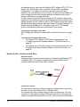
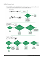
Serial Bridge: Master and Slave Connected to Digi Ports
About This Profile
Use this profile to connect a protocol master to the serial port of one device
server and the protocol slave (or slaves) to the serial port of another device
server. This profile, which is often called a serial bridge, is applicable to
environments that use most IA serial port protocols and to multi-master
environments as well. The network is completely transparent to the serial
devices, which means they do not have to be reconfigured.
Configuration Options
The serial port connections must be configured to meet the requirements of
Chapter 4
IA Profiles and Procedures
43
the attached device, which can be Modbus ASCII, Modbus RTU, DF1 FullDuplex, DF1 Half-Duplex, Omron Hostlink, Omron FINS, and Omron
CompoWay/F. It can also be a serial port protocol that meets Digi’s
definition of a “user defined” protocol, that is, one that has fixed header and
trailer strings that bound all message packets and where each protocol
request is followed by a single response.
For the network connection, Digi recommends TCP sockets, which works
regardless of the serial port protocol specified and provides an efficient and
reliable network service. Another option is UDP sockets, which also works
with all the serial port protocols, although it lacks TCP socket reliability. For
Modbus devices, Modbus/TCP is an option, and for DF1 Full-Duplex
devices, Allen Bradley Ethernet and Ethernet/IP are options.
Locating Setup Information: Slave Side
See "Configuring a Serial-Connected Slave: Generic Procedure" on page
49.
Locating Setup Information: Master Side
•
•
To configure TCP socket or UDP socket communication, see
"Configuring a Serial-Connected Master: TCP/UDP Sockets" on
page 50.
To configure any of the other network communication protocols, see
"Configuring a Serial-Connected Master: Generic Procedure" on
page 50.
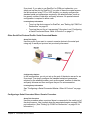
Modbus Profile: Serial-Connected Slave
About This Profile
Use this profile to connect a slave device (or devices) using Modbus RTU
or Modbus ASCII. This profile is applicable to environments in which
multiple masters will control the slave or slaves.
Configuration Options
The serial port connection must be configured for the protocol required by
the slave, in this case Modbus RTU or Modbus ASCII.
The network connection usually does not require configuration. The only
exception is if the master requires COM port redirection. In this case, the
master is an application that resides on a PC, such as a Microsoft Windows
44
Chapter 4 IA Profiles and Procedures
system, and communicates only with devices on COM ports.
Locating Setup Information
•
•
To configure the serial port for Modbus ASCII or Modbus RTU, see
"Configuring a Serial-Connected Slave: Generic Procedure" on
page 49.
To setup a PC and the device server for COM port redirection using
RealPort, see "Setting Up COM Port Redirection" on page 52.
Modbus Profile: Serial-Connected Master
About This Profile
Use this profile to connect a master device using Modbus RTU or Modbus
ASCII to the serial port of the device server.
Configuration Options
The serial port connection must be configured for the protocol required by
the master, in this case Modbus RTU or Modbus ASCII. If the remote slave
supports TCP socket communication, which is the case if the remote slave
is connected to another device server, Digi recommends this option.
Modbus/TCP is the other supported network option. This master can be
configured to control up to 8 slaves.
Locating Setup Information
•
•
Chapter 4
To configure the port for Modbus ASCII or Modbus RTU and the
network for TCP socket communication, see "Configuring a SerialConnected Master: TCP/UDP Sockets" on page 50.
To configure the port for Modbus ASCII or Modbus RTU and the
network for Modbus/TCP, see "Configuring a Serial-Connected
Master: Generic Procedure" on page 50.
IA Profiles and Procedures
45
DF1 Profile: Serial-Connected Slave
About This Profile
Use this profile to connect a slave device (or devices if multiple slaves are
connected) using DF1 Full-Duplex and DF1 Half-Duplex protocols.
Configuration Options
The serial port connection must be configured for the protocol required by
the slave, in this case DF1 Full-Duplex or DF1 Half-Duplex.
The network connection usually does not require configuration. The only
exception is if the master requires COM port redirection. In this case, the
master is an application that resides on a PC, such as a Microsoft Windows
system, and communicates only with devices on COM ports.
Locating Setup Information
•
•
To configure the serial port of the device server for DF1 Full-Duplex
or DF1 Half-Duplex, see "Configuring a Serial-Connected Slave:
Generic Procedure" on page 49.
To setup a PC and the device server for COM port redirection using
RealPort, see "Setting Up COM Port Redirection" on page 52.
DF1 Profile: Serial-Connected Master
About This Profile
Use this profile to connect a master device using DF1 Full-Duplex and DF1
Half-Duplex protocols to the serial port.
46
Chapter 4 IA Profiles and Procedures
Configuration Options
The serial port connection must be configured for the protocol required by
the master, in this case DF1 Full-Duplex or DF1 Half-Duplex. If the remote
slave supports TCP socket communication, which is the case if the remote
slave is connected to another device server, Digi recommends this option.
For DF1 Full-Duplex users, Allen Bradley Ethernet and Ethernet/IP are
other supported network options.
Locating Setup Information
•
•
To configure the port for DF1 Full-Duplex or DF1 Half-Duplex and
the network for TCP socket communication, see "Configuring a
Serial-Connected Master: TCP/UDP Sockets" on page 50.
To configure the port for DF1 Full-Duplex and the network for Allen
Bradley Ethernet or Ethernet IP, see "Configuring a SerialConnected Master: Generic Procedure" on page 50.
Omron Family Profile: Serial-Connected Slave
About This Profile
Use this profile to connect a slave device (or devices) using one of the
Omron serial port protocols, Hostlink, FINS, or CompoWay/F.
Configuration Options
The serial port connection must be configured for the protocol required by
the slave, Hostlink, FINS, or CompoWay/F.
The network connection usually does not require configuration. The only
exception is if the master requires COM port redirection. In this case, the
master is an application that resides on a PC, such as a Microsoft Windows
system, and communicates only with devices on COM ports.
Locating Setup Information
•
•
Chapter 4
To configure the serial port of the device server for any of the Omron
protocols, see "Configuring a Serial-Connected Slave: Generic
Procedure" on page 49.
To setup a PC and the device server for COM port redirection using
RealPort, see "Setting Up COM Port Redirection" on page 52.
IA Profiles and Procedures
47
Omron Family Profile: Serial-Connected Master
About This Profile
Use this profile if you want to connect a master device to the serial port
using one of the Omron serial port protocols, Hostlink, FINS, or
CompoWay/F.
Configuration Options
The serial port connection must be configured for the protocol required by
the master, in this case Hostlink, FINS, or CompoWay/F. If the remote
slave supports TCP socket communication, which includes a slave
connected to another device server, Digi recommends this network option.
UDP Sockets is another supported network option.
Locating Setup Information
To configure the port for one of the Omron protocols and the network for
TCP or UDP socket communication, see "Configuring a Serial-Connected
Master: TCP/UDP Sockets" on page 50.
Other Serial Port Protocol Profile: Serial-Connected Slave
About This Profile
Use this profile if you want to connect a slave device to the serial port using
any IA serial port protocol not previously discussed.
Configuration Options
In this configuration, you do not set up the port of the device server for an
48
Chapter 4 IA Profiles and Procedures
IA protocol. If you plan to use RealPort for COM port redirection, you
simply set up the port for RealPort. If you plan to have the master access
the device server using TCP or UDP sockets, you simply configure the
standard serial port parameters required by the attached slave, such as
line speed, number of data bits, and parity scheme. No special network
configuration is required in either case.
Locating Setup Information
•
•
To set up the device server for RealPort, see "Setting Up COM Port
Redirection" on page 52.
To set up the port for an “unsupported” IA protocol, see "Configuring
a Serial-Connected Slave: Other IA Protocol" on page 51.
Other Serial Port Protocol Profile: Serial-Connected Master
About This Profile
Use this profile if you want to connect a master device to the serial port
using any IA serial port protocol not previously discussed.
Configuration Options
In this configuration, you do not set up the port of the device server for an
IA protocol. You simply configure the standard serial port parameters
required by the attached master, such as line speed, number of data bits,
and parity scheme and then configure the port for autoconnection.
Locating Setup Information
See "Configuring a Serial-Connected Master: Other IA Protocol" on page
51.
Configuring a Serial-Connected Slave: Generic Procedure
About This Procedure
Use this procedure when a protocol slave is connected to the serial port of
the device server. Use it except when the associated master requires COM
port redirection. (See "Setting Up COM Port Redirection" on page 52 for
information.)
Chapter 4
IA Profiles and Procedures
49
Procedure
1. Access the web interface by entering the device server IP address in a
browser’s URL window.
2. Log in to the device server as root. The default password is dbps.
3. From the main menu, choose Setup Wizards > Industrial Protocols.
4. Choose the serial port protocol required by the slave that is connected
to the serial port.
5. Choose Slave as the device type.
Any number of network masters can communicate with the slave.
Configuring a Serial-Connected Master: Generic Procedure
About This Procedure
Use this procedure when a protocol master is connected to the serial port
of the device server. Use it except when the master requires TCP socket or
UDP socket communication. (See "Configuring a Serial-Connected Master:
TCP/UDP Sockets" on page 50 for information.)
Procedure
1. Access the web interface by entering the device server IP address in a
browser’s URL window.
2. Log in to the device server as root. The default password is dbps.
3. From the main menu, choose Setup Wizards > Industrial Protocols.
4. Choose the serial port protocol required by the master.
5. Choose Master as the Mode.
6. Configure up to 8 network slaves.
Configuring a Serial-Connected Master: TCP/UDP Sockets
About This Procedure
Use this procedure in the following situations:
• When a protocol master using one of the supported serial port
protocols (Modbus ASCII, Modbus RTU, DF1 Full-Duplex, DF1 HalfDuplex, FINS, Hostlink, CompoWay/F or a protocol that meets Digi’s
definition of a “user-defined” protocol) is connected to the serial port
• When the master requires TCP or UDP sockets for network
communication
Procedure
1. Access the web interface by entering the device server IP address in a
browser’s URL window.
2. Log in to the device server as root. The default password is dbps.
3. From the main menu, choose Setup Wizards > Industrial Protocols.
4. Choose the serial port protocol required by the master.
50
Chapter 4 IA Profiles and Procedures
5. Choose Master as the Mode.
6. Configure up to 8 network slaves.
7. Change the default socket number only if required.
Configuring a Serial-Connected Slave: Other IA Protocol
About This Procedure
Use this procedure in the following situations:
• When the device connected to the serial port is a slave that is using
a “non-supported” serial-port protocol, that is, the serial port protocol
is not Modbus ASCII, Modbus RTU, DF1 Half-Duplex, DF1 FullDuplex, FINS, Hostlink, CompoWay/F, or a protocol that meets the
definition of a “user-defined” protocol
• When you do not want to set up the device server for RealPort COM
Port redirection
•
When multiple masters will not be communicating with this slave
Procedure
1. Access the web interface by entering the device server IP address in a
browser’s URL window.
2. Log in to the device server as root. The default password is dbps.
3. From the main menu, choose Configure > Port.
4. From the Port configuration screen, set the Device type to Printer,
adjust other serial port communication parameters as required by the
connected slave, and click Submit.
5. Choose Advanced, check Binary Mode, and click Submit.
Configuring a Serial-Connected Master: Other IA Protocol
About This Procedure
Use this procedure when the device connected to the serial port is a
master that is using a “non-supported” serial-port protocol, that is, the serial
port protocol is not Modbus ASCII, Modbus RTU, DF1 Half-Duplex, DF1
Full-Duplex, FINS, Hostlink, CompoWay/F, or a protocol that meets the
definition of a “user-defined” protocol.
Procedure
1. Access the web interface by entering the device server IP address in a
browser’s URL window.
2. Log in to the device server as root. The default password is dbps.
3. From the main menu, choose Configure > Port.
4. From the Port configuration screen, set the Device type to Modem In,
adjust other serial port communication parameters as required by the
connected master, then choose Submit.
The Terminal type field does not matter.
Chapter 4
IA Profiles and Procedures
51
5. If you want to configure the port to launch an automatic connection to
the slave, click Advanced.
6. Choose Enable Autoconnect
7. Specify the IP address of the slave.
8. Specify a TCP port to use for this connection. If this is a connection to
another device server, use 2101 as the TCP port number.
9. If you want the autoconnection to launch immediately, choose Force
DCD.
10. Choose Binary Mode.
11. If you want to enable UDP sockets (instead of TCP sockets), choose
UDP Serial, use the online help for information on completing
configuration task.
12. When you complete configuration, click Submit.
Setting Up COM Port Redirection
About These Procedures
Use these procedures when a slave is connected to the serial port of the
device server and the master, which must be an application residing on a
Microsoft Windows system, requires COM port redirection.
Setup Tasks: An Overview
To enable Com port redirection--which requires that RealPort software be
running on the same PC as the master application--complete the following
tasks:
1. Configure the serial port for RealPort.
See "Procedure: Configuring the Serial Port for RealPort" on page 53.
2. Install RealPort software on a host system.
Note:
52
See the RealPort Installation Guide on the Digi CD under documentation.
Chapter 4 IA Profiles and Procedures
3. Configure the port on the RealPort PC.
See the PC’s documentation for information on configuring serial ports.
Procedure: Configuring the Serial Port for RealPort
Use this topic for information on configuring the Digi One IAP.
1. Access the Digi One IAP configuration from a web browser by entering
the device’s IP address in the browser’s URL window.
2. Log on to the Digi One IAP as the root user as shown. The default
password is dbps.
3. Do one of the following:
If the slave is using a supported
serial port protocol
Choose Port from the main menu.
Set the Device Profile to IA.
Click Apply and enter the protocol
information.
If the slave is not using a supported
serial port protocol
Choose Setup Wizards > RealPort.
Use the wizard to complete
configuration.
4. Use the Add Digi RealPort wizard and the associated help text to
configure the RealPort driver with the IP address and TCP port number
used by the device server.
5. Follow the prompts to complete configuration of the RealPort driver.
Enabling Pass-Through Port
About these procedures
The Digi One IAP has a second DIP switch on the top of the device for
enabling the pass-through port. When the pass-through port DIP switch is
enabled (ON), the DIP switch bank for EIA-232/422/485 operates for the
screw terminal port only. The screw terminal port is port 1. The DB-9 serial
port operates as the second port supporting only EIA-232.
The following are the procedures to enable the pass-through port as well
as diagnostic and troubleshooting tips for using the pass-through port.
Procedure: Enabling the pass-through port
1. While the unit is off, slide the pass-through switch to ON.
2. Power up the unit.
3. Install RealPort from the Access Resource CD under Software.
Note:
If the unit has already been configured and you are adding the pass-through
port, reboot the unit after enabling the pass-through port. If RealPort is
installed before the pass-through port is enabled, the driver must be
reinstalled. Configure the pass-through port as the Master port. See
"Configuring a Serial-Connected Master: Other IA Protocol" on page 51.
Running Diagnostics
The following diagrams are for the screw terminal loopback to be used
when testing two port functionality with the user diagnostics. When running
diagnostics, connect to the DB-9. When running user diagnostics in single
Chapter 4
IA Profiles and Procedures
53
port mode, remove the TS-9 loopback.
#1
#9
Screw Terminal
Connector
Pin 1
Pin 2
Pin 3
Pin 4
Pin 5
Pin 6
Pin 7
Pin 8
Pin 9
232
RTS
DTR
Tx
RI
GND
Rx
DSR
CTS
DCD
485
RTS+
RTSTx+
TxGND
Rx+
RxCTS+
CTS-
232 Loopback
for screw terminal
Connect Pin 1 to 8
Connect Pins 2,4,7,9
Connect Pin 3 to 6
485 Loopback
for screw terminal
Connect Pin 1 to 8
Connect Pin 2 to 9
Connect Pin 3 to 6
Connect Pin 4 to 7
Updating POST Code
This procedure shows you how to upgrade POST code from a file or TFTP.
Typically, POST upgrades are not required and should only be done if the
firmware release notes indicate that this step is required.
Note:
The preferred method is to use your web browser and download the file onto
your PC. TFTP, however, is often used in UNIX environments, so TFTP is
supported as well.
Prerequisite
This procedure assumes that:
• You have already downloaded the firmware file from the Digi web site
• TFTP is running (if you are using the TFTP option)
Procedure
Open a web browser and enter the device server’s IP address in the
URL window.
2. When the device server prompts you to log in, enter the following:
• User Name is root
• The root default password is dbps
1.
3.
54
Choose Upgrade Firmware from the main menu.
Chapter 4 IA Profiles and Procedures
From the dropdown menu, select Boot/POST.
5. Click Browse to select the Boot/Post image.
6. Click Update.
4.
Chapter 4
IA Profiles and Procedures
55
RealPort Decision Guide
56
Chapter 4 IA Profiles and Procedures
Special Features: Wireless
Chapter 5
Use this chapter for the initial configuration of your Digi Wireless device.
After the initial configuration, the device can be configured using the same
methods as the other Digi TS family products.
Configuration Considerations
The Digi wireless devices work ONLY with the antennae provided. You can
use the wizard available on the Software and Documentation CD to
configure your wireless device. You will need an Ethernet cable and a
network PC to configure the wireless Digi device. After assigning the IP
address, access the device from your browser by entering the IP address
in the URL address bar.
Initial Configuration Using Ethernet
1. Connect serial cable, Ethernet cable, and power supply.
2. Insert the CD in the drive. The configuration wizard will automatically
start. Follow the steps in the wizard (either for Microsoft Windows or
Unix) to configure the device.
Or:
If you do not want to use the wizard, click Cancel and follow the
remaining procedure steps to set up the IP address and configure the
device through the web interface.
3. Select Discover Digi Device (from the CD).
4. Select the wireless device and assign the IP address.
5. Click Set IP.
6. Enter the IP address, Subnet, and Gateway mask and click OK.
Chapter 5
Special Features: Wireless
57
7. Select the device and click Configure to launch your browser.
8. Enter the username root and password dbps and click OK.
The home screen appears.
9. Click Network > Wireless LAN
58
Chapter 5 Special Features: Wireless
10. .Enter parameters, click Apply to save.
11. Click Reboot for changes to take effect.
Note:
WARNING!!!!! changing the Advanced Network Settings could cause you to
‘lose’ your device on the Network.Digi International recommends that you do NOT
alter the Advanced Network Settings. If you alter these settings - you may need to
reset your device with the reset button and reconfigure your device as if it
were new. See "Resetting Configuration to Defaults" on page 90 for
instructions.
Be advised these settings are correct for most environments.
12. Unplug the Ethernet cable from the Digi device, disconnect the power,
and power the unit up (reboot).
Configuration is complete.
Chapter 5
Special Features: Wireless
59
60
Chapter 5 Special Features: Wireless
Chapter 6
Special Features: Software Selectable
MEI
This chapter describes configuring MEI (Multiple Electrical Interface)
settings through the web interface for the PortServer TS 8 MEI* and
PortServer TS 16 MEI*. The internal MEI settings are switched to EIA-232
by default.
*Except for the PortServer TS 8 MEI and PortServer TS 16 MEI devices,
the remaining Digi TS Family have external DIP switches for MEI settings.
About MEI Settings
PortServer TS 8/16 MEI devices are shipped with the ports switched to
EIA-232 by default. The 232 drivers will generate voltages of 6V max. This
voltage is well within the tolerances of EIA 422/485. The 232 drivers are
current limited so they can’t over-drive another EIA-422/485 output and
damage their devices.
The same engineering applies if a port is set at EIA-422 and a 232 device
is connected to it. The voltage generated is within the tolerance of the
serial device and will not damage either device.
In either case, your serial device may or may not produce ‘data chatter’ that is, text strings that have no meaning. This is an indication that the MEI
settings are not in agreement and should be configured.
If there is a loss of power to the unit, the device will not lose the MEI
configuration. After it boots up, it will recall and apply the last MEI settings.
Configure the MEI Switches
1. Log into the Digi PortServer TS
2. Click Serial Ports > port #
3. Select your port profile for your environment and click Apply.
4. Click MEI Serial Settings
5. Select the Tx Control setting for your scenario.
Chapter 6
Special Features: Software Selectable MEI
61
Note:
Select Tx Control > Always on if this device is the only one transmitting on
one wire pair, such as a single master in a master/slave configuration or if
only tow devices are attached. Use Tx Control > Auto if multiple devices need
to share the bus in a dual master scenario or if the device is acting as slave in
a multidrop environment. See "Four-Wire Multi-Drop Network Scenarios" on
page 63 for more information about multi-drop scenarios.
6. Click Apply and the settings will take effect.
7. Repeat steps 2-6 for each port.
8. If you have not done so already, connect your serial device to the
appropriate serial port.
Table for Pin Outs
Pin
Number
62
EIA-232
Signal
Standard 10-Pin
EIA-422/485
Signal
(4/8 Wire)
Optional 8 pin
EIA-422/485
Signal
(Alt-4-Wire)
EIA-485 Signal
(2-Wire Mode)
Data- (B)
01
RI
TXD- (B)
02
DSR
RxD- (B)
RxD- (B)
03
RTS
RTS+ (A)
TxD+ (A)
04
CGND
CGND
CGND
CGND
05
/TxD
TxD+ (A)
06
/RxD
RxD+ (A)
RxD+ (A)
Data+ (A)
07
SGND
SGND
SGND
SGND
08
CTS
CTS+
09
DTR
RTS- (B)
TxD- (B)
Chapter 6 Special Features: Software Selectable MEI
Pin
Number
10
EIA-232
Signal
Standard 10-Pin
EIA-422/485
Signal
(4/8 Wire)
DCD
Optional 8 pin
EIA-422/485
Signal
(Alt-4-Wire)
EIA-485 Signal
(2-Wire Mode)
CTS- (B)
Set the Supported Baud Rate for Multi-drop Support
The PortServer TS 8/16 MEI requires setting a baud rate range in order to
perform the automatic transmitter control. This setting does not influence
the performance in EIA-232 mode or for EIA-422/485 configurations where
the transmitter is always on.
The range supported by default is: 50 -230400 bps
To change the supported baud rate range
1. Select System > MEI.
2. Select Baud rate from the drop down box.
3. Select Enable all serial ports (to enable the serial port transmitter) if
appropriate.
4. Click Apply for configuration to take effect.
Four-Wire Multi-Drop Network Scenarios
There are two scenarios of devices on a four-wire multi-drop network. The
Master and the Slave. A Master has a dedicated pair of wires to talk to the
Slaves. The Slaves share a return pair to the Master and need to control
their transmitters so that only one device at a time uses that pair. Following
are the specific procedures to set up a Master or Slave MEI setting.
MEI Configuration for a Single Master:
1. Click Serial Ports > port # > MEI Serial Settings
2. Select 422/485, Tx Control > Always on.
3. Select Enable alternative pinout (altpin). This option is only enabled
with 4 Wire. See the following table for pin out information.
4. Click Apply for settings to take effect.
Chapter 6
Special Features: Software Selectable MEI
63
MEI Configuration for a Slave:
1. Click Serial Ports > port # > MEI Serial Settings
2. Select 422/485, Tx Control > Auto.
3. Select Enable alternative pinout (altpin). This option is only enabled
with 4 wire. See the "MEI Configuration for a Slave:" on page 64 for
more information.
4. Click Apply for settings to take effect.
Note:
64
You do not need to reboot after you click Apply for MEI settings to take effect.
Chapter 6 Special Features: Software Selectable MEI
Special Features: Embedded Modem
Chapter 7
Embedded Modem
The PortServer TS 1 M MEI and PortServer TS 3 M MEI function as both
terminal server and modem. The embedded modem can be used with PPP,
dial-in, dial-out, or auto answer and conforms to the standard AT command
interface.
The PortServer TS 1 M MEI and PortServer TS 3 M MEI allow
• remote monitoring
• diagnostics
• data collection
• dial-up, wireless, or Ethernet connectivity
For a complete AT command reference see the AT Command reference
from the CD under Documentation.
The remaining ports can be configured the same as any Digi TS Family
product, either through the web interface or command line.
Installing the PortServer TS 1/3 M MEI
The PortServer TS 1/3 M MEI comes with a bi-directional cable for
connecting the modem (port 1) to the phone line.
1. Plug the cable with the ferrite end into the modem port.
2. Plug other end into phone line.
3. Connect Ethernet.
4. Connect power supply.
Configuring the PortServer TS 1/3 M MEI
1. Follow the setup wizard from the CD to assign an IP.
2. If the wizard scenarios need additional configuration, login to the device
IP from the URL.
3. Select Serial Ports > Change profile
4. Select the appropriate profile (Custom shows all options)
Chapter 7
Special Features: Embedded Modem
65
5. Enter the appropriate parameters and click Apply to save.
6. Click Reboot for changes to apply.
66
Chapter 7 Special Features: Embedded Modem
Special Features: Modem Emulation
Chapter 8
Modem Emulation
Modem emulation enables a system administrator to configure a
networked Digi device to act as a modem. The Digi device emulates
modem responses to a serial device and seamlessly sends and receives
data over an Ethernet network instead of a PSTN (Public Switched
Telephone Network). The advantage for a user is the ability to retain legacy
software applications without modification and use a less expensive
Ethernet network in place of public telephone lines.
Note:
Port one on the PortServer TS 1/3 M MEI is an actual embedded modem. The
remaining ports are capable of emulating a modem.
To use a Digi device for modem emulation, do the following:
• Use a cable with the correct wiring pinouts (see "Modem Emulation
Cable Signals" on page 68)
• Configure the serial ports and device type with the Web Interface
serial port profile - Modem Emulation
Note:
Before AT commands are accepted, DSR must go high on the Digi device.
Common User Scenarios
The Digi device in modem emulation mode allows for the easy replacement
of modems in almost any environment where there is a LAN or WAN.
In Diagram A, the PortServer TS 1 MEI replaces a modem connected to a
workstation running an application. The PortServer TS 1 MEI allows for the
use of software applications without modification by responding to all the
AT commands configured in the workstation application. The PortServer
TS 1 MEI connects to the IP Address of the server when an
ATDT ipaddress:port (ATDT 192.168.25.5:50001)
command is issued. Once the remote device establishes the TCP
connection, a CONNECT message is sent to the serial port and only then
does the Digi device switch from AT command mode to data mode. Using
the modem escape sequence or dropping DTR on either side terminates
the connection. A DISCONNECT message will be sent to the application if
Chapter 8
Special Features: Modem Emulation
67
the remote side closes the TCP connection.
User Scenario-Diagram B
Workstation
Serial cable
O NE
TS
#1
Digi One TS
D IGI
Ethernet
Workstation
#2
Digi One TS
192.168.25.30
D IGI
O NE
TS
Serial cable
In Diagram B, two Digi devices will replace modems on both sides of the
connection. The initiation of the connection occurs with either of the Digi
devices. If both ends are Digi devices, the TCP listening port number is
50001 for port 1. An example of the connection command is ATDT
192.168.25.30:50001. Upon establishing a successful TCP
connection, a CONNECT message is sent to the serial port and only then
does the Digi device switch from AT command mode to data mode. After
the CONNECT is received, the transmission of data begins. Using the
modem escape sequence or dropping DTR on either side terminates the
connection.
Modem Emulation Cable Signals
Use the following signal assignments to make a cable connecting the Digi
device to a serial device.
DSR and DTR on the serial device side are connected to the DSR signal of
the Digi device.
Scenarios for Modem Emulation
Outgoing Modem Emulation Connection
Serial device sends ATDx.x.x.x:y command, which triggers the Digi device
to establish a telnet connection to destination IP=x.x.x.x, port=y.
68
Chapter 8 Special Features: Modem Emulation
Incoming Modem Emulation Connection
A device on the network telnets to port 50001 (50000+1 = 1st serial port).
This incoming connection triggers the Digi device to generate a RING on
the serial port. The device attached to the serial port will answer the RING
and the connection is established.
Modem Emulation Pooling
This is a combination of Incoming Modem Emulation Connection and a
hunt group. A device on the network telnets to port 50000. The Digi device
checks if a serial port configured for modem emulation is available. If so, it
connects to the port, otherwise returns an error.
Modem Emulation Bridge
A combination of Outgoing and Incoming Modem Emulation Connections,
in which both serial devices require to talk to a modem. The first serial
device telnets to the second device using ATDx.x.x.x:y, the second device
gets a RING and accepts the incoming telnet connection.
Originating, Answering, and Disconnecting Calls
In the following table, an application requests a TCP session with the Digi
device. The table displays the responses of the Digi device and application
as they negotiate a TCP connection.
Application AT
Command
Digi Device Response
AT&F
ATDT ipaddress:TCPport#
<P>+++<P>
ATH
Notes
OK.
AT command request to restore defaults to factory settings-Digi device responds OK.
Receives request to start a
TCP session. CONNECT
115200.
Request to start TCP session with IP address and TCP
port number of the Digi device-which then starts a TCP
session
OK
Escape sequence is sent <P> is Pause in seconds with
“+++” being the escape sequence in ASCII characters Digi device switches from AT command to data mode
NO CARRIER response sent
Disconnect AT command is sent-Digi device responds
with NO CARRIER
In the following table, the Digi device receives a request for a connection.
AT Command
ATA (or ATS0=n)
Digi Device Response
Notes
RING
The Digi device sends a Call Notification
CONNECT 115200
Manual (ATA) or Auto Answer (ATS0=n) response-the
Digi device sends a CONNECT message when the
TCP session is started
NO CARRIER
The Digi device sends a NO CARRIER message when
the remote disconnects
Originating Calls
To send data to a Digi device, enter the following information for your
application replacing the telephone number with the Digi device’s IP
address and TCP port number. Enter the following command:
Chapter 8
Special Features: Modem Emulation
69
ATDT ipaddress:tcp_port#
an example is ATDT 146.135.13.5:50001
Answering Calls
The Digi device listens on a pre-defined TCP port to receive data. When
the Digi device receives a call notification (RING) through a serial port to
begin a TCP connection, it needs to reply with an ATA or a pre-configured
Auto-Answer to answer the call.
Note:
The TCP ports assigned to the serial ports are as follows:
Serial port 1 listens on TCP port 50001
Serial port 2 listens on TCP port 50002
Serial port 3 listens on TCP port 50003
Serial port 4 listens on TCP port 50004
Disconnecting Calls
The TCP connection disconnects by either dropping the DTR signal on the
serial port or sending the escape sequence <P>+++<P> to the Digi device.
<P> represents a one second pause.
Disconnecting Calls-Digi Device
The Digi device sends a NO CARRIER response to the serial port when
the network connection is dropped.
Modem Emulation AT Command Set
AT
Command
ATA
70
Result
Code
Function
Answer command: The Digi device will go off hook and answer a TCP
connection request.
Chapter 8 Special Features: Modem Emulation
AT
Command
Function
Result
Code
This command directs the Digi device to go on-line, dial according to the IP
address entered as follow 191.1.2.3:12 and attempt to establish a TCP
connection. If no dial string is supplied, the Digi device will respond no dial
tone.
Note: If the ATD command is issued before the S1 register has cleared, the
modem will respond with the NO CARRIER result code.
Dial Modifiers. The valid dial string parameters are described below.
Punctuation characters may be used for clarity with parentheses, hyphen,
and spaces being ignored.
ATD<IP>
:
<TCP
PORT>
ATEn
Command echo. The Digi device enables or disables the echo of characters
to the DTE according to the parameter supplied. The parameter value, if
valid, is written to S14 bit 1.
E0 : Disables command echo
E1 : Enables command echo
OK n=0 or 1
ERROR
Otherwise
ATH
Disconnect (Hang up) command
This command initiates a hang up sequence.
H0 : Disconnect the TCP session if the modem is currently on line.
H1 : If on-hook, the Digi device will go off-hook and enter command mode.
OK n=0 or 1
ERROR
Otherwise
ATIn
Identification command
I0 reports product code. Example: Digi device
I1 reports 255
I2 reports “OK”
I3 reports “OK”
I4 reports DIGI DS_TS
I5 reports “OK”
I6 reports “OK”
I7 reports “OK”
I8 reports “ERROR”
I9 reports “ERROR”
Chapter 8
Special Features: Modem Emulation
OK n=0 or 9
ERROR
Otherwise
71
AT
72
Result
Code
Function
Command
ATLn
Accepted but ignored.
OK n=0 or 3
ERROR
Otherwise
ATMn
Accepted but ignored.
OK n=0 or 3
ERROR
Otherwise
ATNn
Accepted but ignored.
OK n=0 or 1
ERROR
Otherwise
ATOn
Return to On-Line Data Mode.
This command determines how the modem will enter the on-line data mode.
If the modem is in the on-line command mode, the modem enters the online data mode. If the modem is in the off-line command mode (no
connection), ERROR is reported.
O0Enters on-line data mode. Handling is determined by the Call
Establishment task. Generally, if a connection exists, this command
connects the DTE back to the remote modem after an escape (+++).
O1Same as above
OKn = 0 or 1
and a
connection
exists.
ERROR
Otherwise or if
not connected.
ATP
Accepted but ignored.
OK
ATQn
Quiet Results Codes Control command.
The command enables or disables the sending of the result codes to the
DTE according to the parameter supplied. The parameter value, if valid, is
written to S14 bit 2.
Q0 Enables result code to the DTE (Default).
Q1 Disables result code to the DTE
OK n=0 or 1
ERROR
Otherwise
ATSn
Read/Write S- Register.
n
Establishes S-register n as the last register accessed
n=v Sets S-Register n to the value v.
n? Reports the value of S-Register n.
ATT
Accepted but ignored..
OK
ATVn
Result Code Form. This command selects the sending of short-form or longform codes to the DTE. The parameter, if valid, is written to S14 bit 3.
V0 Enables short-form (terse) result codes. Line feed is not issues before a
short-form result.
V1 Enables long-form (verbose) results codes (Default).
OK n=0 or 1
ERROR
Otherwise
ATWn
Accepted but ignored.
OK n=0 to 3
ERROR
Otherwise
ATXn
Accepted but ignored.
OK n=0 to 3
ERROR
Otherwise
ATYn
Accepted but ignored.
OK n=0 or 1
ERROR
Otherwise
ATZn
Accepted but ignored. (Soft Reset and restore Profile).
OK n=0 or 1
ERROR
Otherwise
Chapter 8 Special Features: Modem Emulation
AT
Function
Command
Result
Code
AT&Cn
DCD Option. The Digi device controls the DCD output in accordance with
the parameter supplied. The parameter value, if valid is written to S21 bit 5.
&C0 DCD remains ON at all times.
&C1 DCD follows the state of the connection
OK n=0 or 1
ERROR
Otherwise
AT&Dn
DTR Option. This command interprets the ON to OFF transition of the DTR
signal from the DTE in accordance with the parameter supplied. The
parameter value, if valid, is written to S21 bits 3 and 4. Also see S25.
&D0 -DTR is ignored (assumed ON). Allows operation with DTEs which
do not provide DSR.
&D1DTR drop is interpreted by the modem as if the asynchronous escape
sequence had been entered. The modem returns to asynchronous
command state without disconnecting.
&D2DTR drop causes the modem to hang up. Auto-answer is inhibited.
(Default.)
&D3DTR drop causes the modem to perform a soft reset as if the Z
command were received. The &Y setting determines which profile is loaded.
OK n=0 to 3
ERROR
Otherwise
AT&Fn
Restore Factory Configuration (Profile)
The device loads the factory default configuration (profile). The factory
defaults are identified for each command and in the S-Register descriptions.
A configuration (profile) consists of a subset of S-Registers.
&F0Restore factory configuration 0.
&F1Restore factory configuration 1.
OK n=0 or 1
ERROR
Otherwise
AT&Jn
Accepted but ignored.
OK n=0 or 1
ERROR
Otherwise
AT&Gn
Accepted but ignored.
OK n=0 or 1
ERROR
Otherwise
AT&Jn
Accepted but ignored.
OK n=0 or 1
ERROR
Otherwise
AT&Kn
Flow control. This command defines the DTE/DCE flow control mechanism.
The parameter value, if valid, is written to S39 bits 0, 1, and 2.
&K0 Disables flow control
&K3 Enables RTS/CTS flow control (Default)
&K4 Enables XON/XOFF flow control
&K5 Enables transparent XON/XOFF flow control
&K6 Enables both RTS/CTS and XON/XOFF flow control.
OK n=0,3,4,5,or
6
ERROR
Otherwise
AT&Ln
Accepted but ignored.
OK n=0, 1, 2
ERROR
Otherwise
AT&Mn
Accepted but ignored.
OK n=0, 1, 2
ERROR
Otherwise
AT&Pn
Accepted but ignored.
OK n=0, 1, 2
ERROR
Otherwise
AT&Qn
Accepted but ignored.
OK n=0 to 8
ERROR
Otherwise
Chapter 8
Special Features: Modem Emulation
73
AT
74
Result
Code
Function
Command
AT&Rn
RTS/CTS Option
This selects how the Digi device controls CTS. CTS is modified if hardware
flow control is selected (see &K command). The parameter value, if valid, is
written to S21 bit2.
&R0CTS reflects the ability of the modem to transmit data. For example,
CTS will drop during retrains. In sync mode, CTS tracks the state of RTS;
the RTS-to-CTS delay is defined by S26. In async mode, CTS is normally
ON and will turn OFF only if required by flow control.
&R1CTS forced on (default). In sync mode, CTS is always ON (RTS
transitions are ignored). tracks the state of RTS. In async mode, CTS is
normally ON and will turn OFF only if required by flow control.
&R2CTS follows RTS.
OK n=0 or 1
ERROR
Otherwise
AT&Sn
DSR Override
This command selects how the modem will control DSR. The parameter
value, if valid, is written to S21 bit 6.
&S0DSR will remain ON at all times. (Default.)
&S1DSR will become active after answer tone has been detected and
inactive after the carrier has been lost.
OK n=0 or 1
ERROR
Otherwise
AT&Tn
Accepted but ignored.
OK n= 0
ERROR
Otherwise
AT&V
Display Current Configuration and Stored Profiles
There is no NVRAM support currently.
OK
AT&Vn
Accepted but ignored.
OK n=0 to 5
ERROR
Otherwise
AT&V6
Display current IP settings of the device
OK
AT&Wn
Accepted but ignored.
OK n=0 or 1
ERROR
Otherwise
AT&Xn
Accepted but ignored.
OK n=0 or 1
ERROR
Otherwise
AT&Yn
Accepted but ignored.
OK n=0 or 1
ERROR
Otherwise
AT&Zn
&Zn=x - Store Telephone Number.
Currently not supported
OK n=0 or 3
ERROR
Otherwise
AT\An
Accepted but ignored.
OK n=0 to 3
ERROR
Otherwise
AT\Gn
Accepted but ignored.
OK n=0 or 1
ERROR
Otherwise
AT\Kn
Accepted but ignored.
OK n=0 to 5
ERROR
Otherwise
Chapter 8 Special Features: Modem Emulation
AT
Function
Command
Result
Code
AT\Nn
Operating Mode
This command controls the preferred error correcting mode to be negotiated
in a subsequent data connection.
\N0 Selects normal speed buffered mode
\N1 Serial interface selected - Selects direct mode
\N2 Accepted but ignored.
\N3 Accepted but ignored.
\N4 Accepted but ignored.
\N5 Accepted but ignored.
OK n=0 to 5
ERROR
Otherwise
AT\Vn
Accepted but ignored.
OK n=0 or 1
ERROR
Otherwise
AT+MS
Accepted but ignored.
OK
AT+MI
Accepted but ignored.
OK
AT%Cn
Accepted but ignored.
OK n=0 to 3
ERROR
Otherwise
Chapter 8
Special Features: Modem Emulation
75
S-Registers
Register
Function
Range
Units
Saved
S0
Rings to Auto-Answer
Sets the number of rings required before the
Digi device automatically answers a call.
Setting this register to Zero disables autoanswer mode.
0-255
Rings
S1
Ring Counter
S1 is incremented each time the modem
detects a ring signal on the telephone line. S1
is cleared if no rings occur over an eight
second interval.
0-255
Rings
S2
Escape Character
S2 holds the decimal value of the ASCII
character used as the escape character. The
default value corresponds to an ASCII ’+’. A
value over 127 disables the escape process,
i.e., no escape character will be recognized.
0-255
ASCII
S3
Carriage Return Character
Sets the command line and result code
terminator character. Pertains to asynchronous
operation only.
0-127
ASCII
13
S4
Line Feed Character
Sets the character recognized as a line feed.
Pertains to asynchronous operation only. The
Line Feed control character is output after the
Carriage Return control character if verbose
result codes are used.
0-127
ASCII
10
S5
Backspace Character
Sets the character recognized as a backspace.
Pertains to asynchronous operation only. The
modem will not recognize the Backspace
character if it is set to a value that is greater
than 32 ASCII. This character can be used to
edit a command line. When the echo command
is enabled, the modem echoes back to the
local DTE the Backspace character, an ASCII
space character and a second Backspace
character; this means a total of three
characters are transmitted each time the
modem processes the Backspace character.
0-32
ASCII
8
*
Default
0
0
*
43
S6
Accepted but ignored.
2-255
s
*
2
S7
Accepted but ignored.
1-255
s
*
50
S8
Accepted but ignored.
0-255
s
*
2
S9
Accepted but ignored.
1-255
0.1 s
*
6
S10
Accepted but ignored.
1-255
0.1 s
*
14
S11
Accepted but ignored.
50-255
0.001 s
*
95
S12
Escape Prompt Delay
Defines the maximum period, in fiftieths of a
second, allowed between receipt of the last
character of the three escape character
sequence from the DTE and sending of the OK
result code to the DTE. If any characters are
detected during this time, the OK will not be
sent. Note that sending of the OK result code
does not affect entry into command mode.
0-255
0.02 s
*
50
76
Chapter 8 Special Features: Modem Emulation
Register
Function
Range
Units
-
-
Saved
Default
S13
Reserved
S14
General Bit Mapped Options Status
Indicates the status of command options.
Default:138 (8Ah) (10001010b)
Bit 0This bit is ignored.
Bit 1Command echo (En)
0 =Disabled (E0)
1 =Enabled (E1) (Default.)
Bit 2Quiet mode (Qn)
0 =Send result codes (Q0) (Default.)
1 =Do not send result codes (Q1)
Bit 3Result codes (Vn)
0 =Numeric (V0)
1 =Verbose (V1) (Default.)
Bit 4Reserved
Bit 5Tone (T)/Pulse (P)
0 =Tone (T) (Default.)
1 =Pulse (P)
Bit 6Reserved
Bit 7Originate/Answer
0 =Answer
1 =Originate (Default.)
S15
Reserved
-
-
-
S16
Accepted but ignored.
-
-
0
S17
Reserved
-
S18
Accepted but ignored.
0-255
s
S19
Accepted but ignored.
-
-
S20
Accepted but ignored.
0-255
-
Chapter 8
Special Features: Modem Emulation
-
*
138
(8Ah)
-
-
*
0
0
*
0
77
Register
Range
Units
S21
General Bit Mapped Options Status
Indicates the status of command options.
Default:52 (34h) (00110100b)
Bit 0Set by &Jn command but ignored
otherwise.
0 =&J0 (Default.)
1 =&J1
Bit 1Reserved
Bit 2CTS behavior (&Rn)
0 =CTS tracks RTS (&R0)
1 =CTS always on (&R1) (Default.)
Bits 3-4DTR behavior (&Dn)
0 =&D0 selected
1 =&D1 selected
2 =&D2 selected (Default.)
3 =&D3 selected
Bit 5RLSD (DCD) behavior (&Cn)
0 =&C0 selected
1 =&C1 selected (Default.)
Bit 6DSR behavior (&Sn)
0 =&S0 selected (Default.)
1 =&S1 selected
Bit 7Long space disconnect (Yn)
0 =Y0 (Default.)
1 =Y1
-
-
*
52 (34h)
S22
Accepted but ignored.
-
-
*
117
(75h)
78
Function
Saved
Default
Chapter 8 Special Features: Modem Emulation
Register
Function
Range
Units
Saved
Default
S23
General Bit Mapped Options Status
Indicates the status of command options.
Default:62 (3Dh) (00111110b)
Bit 0Grant RDL
0 =RDL not allowed (&T5) (Default.)
1 =RDL allowed (&T4)
Bits 1-3DTE Rate
0 =0 - 300 bps
1 =600 bps
2 =1200 bps
3 =2400 bps
4 =4800 bps
5 =9600 bps
6 =19200 bps
7 =38400 bps or higher (Default.)
Bits 4-5Assumed DTE parity
0 =even
1 =not used
2 =odd
3 =none (Default.)
Bits 6-7not action applied
S24
Accepted but ignored.
0-255
s
S25
Delay to DTR Off
Sets the length of time that the modem will
ignore DTR for taking the action specified by
&Dn. Its units are seconds for synchronous
modes and one hundredths of a second for
other modes
0-255
s or
0.01 s
5
S26
RTS-to-CTS Delay
Sets the time delay, in hundredths of a second,
before the modem turns CTS ON after
detecting an OFF-to-ON transition on RTS
when &R0 is commanded. Pertains to
synchronous operation only.
0-255
0.01 s
1
S27
General Bit Mapped Options Status
-
-
*
73 (49h)
S28
Accepted but ignored.
-
-
*
0
S29
Accepted but ignored.
0-255
10 ms
70
S30
Accepted but ignored.
0-255
10 s
0
S31
Accepted but ignored.
-
-
S32
XON Character
0-255
ASCII
17 (11h)
S33
XOFF Character
0-255
ASCII
19 (13h)
S34
S35 Reserved
-
-
-
S36
Accepted but ignored.
-
-
Chapter 8
Special Features: Modem Emulation
*
62
(3Dh)
*
0
*
*
194
(C2h)
7
79
Register
S37
Function
General Bit Mapped Options Status
Telnet support for modem emulation.
Default:0
Bit 0-1 Send TCP transmit data timer
0 = 100ms
1 = 200 ms
2 = 300 ms
3 = 500 ms
Bits 2-3 Service TCP transmit data watermark
0 = 256
1 = 512
2 =768
3 =1024
Bits 4-5 Service TCP receive data watermark
0 = 256
1 = 512
2 =768
3 =1024
Bits 6-7 Telnet support (RFC 2217)
0 = Disabled
1 = Receive Telnet support enabled
2 = Transmit Telnet support enabled
3 = Receive and Transmit Telnet support
enabled
Range
Units
-
-
Saved
*
Default
0
S38
Accepted but ignored.
0-255
s
20
S39
Flow Control Bit Mapped Options Status
Default:3 (00000011b)
Bits 0-2Status of command options
0 =No flow control
3 =RTS/CTS (&K3) (Default.)
4 =XON/XOFF (&K4)
5 =Transparent XON (&K5)
6 =Both methods (&K6)
Bits 3-7Reserved
-
-
*
3
S40
Accepted but ignored.
-
-
*
104
(68h)
S41
Accepted but ignored.
-
-
*
195
(C3h)
S42 - S45
Reserved
-
-
-
S46
Accepted but ignored.
-
-
*
138
S48
Accepted but ignored.
-
-
*
7
S82
Accepted but ignored.
-
-
128(40h
)
S86
Accepted but ignored.
0-255
-
-
80
Chapter 8 Special Features: Modem Emulation
Register
S91
Function
Range
Accepted but ignored.
0-15
Units
Saved
Default
dBm
10
(Countr
y
depend
ent)
10
(Countr
y
depend
ent)
S92
Accepted but ignored.
0-15
dBm
S95
Accepted but ignored.
-
-
*
0
* Register value may be stored in one of two user profiles with the &W command.
Result Codes
Short
Long Form
Short
Long Form
0
OK
13
CONNECT
7200
84
CONNECT
33600
1
CONNECT
14
CONNECT
12000
91
CONNECT
31200
2
RING
15
CONNECT
14400
165
CONNECT
32000
3
NO CARRIER
16
CONNECT
19200
166
CONNECT
34000
4
ERROR
17
CONNECT
38400
167
CONNECT
36000
5
CONNECT
1200
18
CONNECT
57600
168
CONNECT
38000
6
NO DIALTONE
19
CONNECT
115200
169
CONNECT
40000
7
BUSY
20
CONNECT
230400
170
CONNECT
42000
8
NO ANSWER
59
CONNECT
16800
171
CONNECT
44000
9
CONNECT
0600
61
CONNECT
21600
172
CONNECT
46000
10
CONNECT
2400
62
CONNECT
24000
173
CONNECT
48000
11
CONNECT
4800
63
CONNECT
26400
174
CONNECT
50000
12
CONNECT
9600
64
CONNECT
28800
Chapter 8
Special Features: Modem Emulation
Short
Long Form
81
82
Chapter 8 Special Features: Modem Emulation
Chapter 9
Special Features: Power Over the Serial
Ports
Serial Power Feature
The Serial Power feature available for the PortServer TS MEI Series and
the PortServer TS W MEI Wireless Series allow the Digi device to power a
serial device (power out) or use a serial device to power the Digi device
(power in). The advantage of this feature is to eliminate an external power
supply.
Power out is available on all ports through Ring Indicator (RI) or Data
Terminal Ready (DTR). Power in is available only through RI and only on
port one (1). The Serial Power feature is active on a specific port when that
port is configured for RS 232 operation.
• The power out budget equals one (1) watt (the total amount of
power available). The available power can be divided in any combination between the ports but the following rules must be observed:
— RI = 5 volts @ up to 200 mA (max)
— DTR = 9 volts @ up to 100 mA (max)
— You may use DTR or RI as the source of power (power out) on
any port but you may not use both DTR and RI on the same port.
• Pinout information
— RI is pin 1
— DTR is pin 9
• RI signaling is lost when the pin is used for power
Configuring RI Power
RI Power In
Ring Indicator (RI) power in accepts power into the Digi device only on port
one. Power in is available using the RI pin. The Digi device requires power
in the range of 9-30 VDC @ 525mA (max). Ports 2, 3, and 4 can still supply
power to a serial device through the RI or DTR pins for each port. When
using power in through the RI, the external power supplies (both powered
Ethernet and the barrel connector power supply) are inoperative. Altpin will
not work for RI power in.
Chapter 9
Special Features: Power Over the Serial Ports
83
1. Open the device case and move the black jumper to the following
settings:
P-6 jumper on pins 1 and 2
Note When the jumper is placed correctly
for power in, the jumper will set on
the pins closest to the edge of the
board. The left arrow indicates the
open pin and the right arrow is
pointing to the jumper.
2. Close the device unit enclosure.
RI Power Out
Ring Indicator (RI) power out is available on all ports. The total power
budget for this feature is one (1) watt not to exceed 5 volts @ up to 200mA
on any single port. The following procedure assumes the unit will only be
used for RI power out.
1. Set the port DIP switches to the following places: switch 1 and 3 are up
and 2 and 4 are down (see "Serial Power Table" on page 85 for
illustration).
2. Enable the RI power through the web interface.
3. Connect power supply with the barrel-connector power supply provided
with the device or use powered Ethernet.
Note:
If the unit will be used with RI power in (port 1 only), set the jumper to the
following setting:
P-6 jumper on pins 1and 2
and do not use an external power source. Port 1 cannot be used for both
power in and power out.
Configuring DTR Power
Power Out
Data Terminal Ready (DTR) power out is the factory default on the Digi
device. Total power budget for this feature is one (1) watt not to exceed 9
volts @ up to 100mA to any single port.
1. Set the port DIP switches to EIA 232 (switch 1 is up, 2, 3, and 4 are
down) to enable DTR power.
84
Chapter 9 Special Features: Power Over the Serial Ports
2. Open the port and set DTR high.
Note Here are the pins to verify
the jumper position. The
default position has the
jumper on the two pins
furthest from the edge. DO
NOT MOVE THE JUMPER
FROM THE DEFAULT
UNLESS USING RI POWER
IN.
If you are having trouble with your unit after using the Power over port
feature, you may have tripped the circuit breaker in the unit. You can
identify this by the RI or DTR signal indicators found in the System
Information under Administration on the main menu in the web interface.
Click the port number using serial power. (Remember serial power out is
unavailable if the MEI settings are not 232.)
Under serial power will be a message if the breaker is tripped. Follow the
instructions to reset.
From the command line use the two examples below for additional
information.
display circuitbreaker
Display the status of the circuit breaker
set config circuitbreaker=reset
Reset the circuit breaker
Note:
set config will also give the status of the circuitbreaker state.
Serial Power Table
Use this table for summary information for a serial power setup.
Chapter 9
Special Features: Power Over the Serial Ports
85
.
Quick Summary
Table for Setup of
Serial Power
DTR Power
RI Power
OUT
OUT
IN
DTR ON
DTR OFF
DTR OFF
Switch Settings
DTR setting
1*, 2, 3, 4
86
1
Ports Allowed
1, 2, 3, 4
*unless port 1 is used
for power in
Jumper Pin Settings
P-6 jumper on pins
2&3
(Factory Default)
P-6 jumper on pins
2&3
(Factory Default)
P-6 jumper on pins
1&2
Power Budget
9v @ up to 100mA
one watt
5v @ up to 200 mA
one watt
9 -30 v @ up to
525mA (max)
Chapter 9 Special Features: Power Over the Serial Ports
Special Features: SNMP
Chapter 10
This chapter describes configuring SNMP, the network management
protocol that governs the exchange between nodes and stations.
About SNMP and the Digi Device Agent
This section introduces SNMP and network management in TCP/IP
networks and it describes the device server agent. It discusses the
following:
• Network management components
• SNMP agent
• SNMP traps
• MIB (management information base) support of the Digi device
agent
• Support traps of the Digi device agent
Network Management Components
The TCP/IP network management architecture contains the following
components:
• Managed nodes such as host systems, routers, terminal and communications servers (such as device server) and other network
devices.
•
•
•
•
One or more network managers (also called network management
stations), which are the points from which the network is managed
Agents that reside on managed nodes and retrieve management
information and communicate this information to network managers.
The network management protocol, SNMP, which governs the
exchange of information between the nodes and stations.
Management information, which is the database of information
about managed objects. This database is called the management
information base (MIB).
SNMP Management Agent
Each managed node contains at least one agent—a component that
responds to requests from the network manager—that retrieves network
management information from its node and notifies the manager when
significant events occur.
SNMP Traps
An ‘eventing’ mechanism defined by SNMP is called a trap, which is a
report or “alarm” from a managed node to an SNMP manager that a
significant event has occurred.
MIB Support
The SNMP management agent supports the following MIBs:
Chapter 10 Special Features: SNMP
87
•
•
•
•
Read-write for MIB II (RFC 1213), which is an Internet-standard
MIB, consisting of managed objects from the systems, interfaces, IP,
ICMP, TCP, UDP, transmission, and SNMP group
Read-write for the character-stream devices using SMIv2 MIB (RFC
1658)
Read-write for the RS-232-like hardware devices MIB (RFC 1659)
Read-write for the device server IP Network Control Protocol of the
Point-to-Point Protocol MIB (RFC 1473)
Message Support
The SNMP agent supports the Set, Get, GetNext, and Trap messages as
defined in RFC 1157. These messages are used as follows:
• Set, which means set the value of a specific object from one of the
supported MIBs
• Get, which means retrieve the value of a specific object form one of
the supported MIBs
• GetNext, which means retrieve the value of the next object in the
MIB
• Trap, which means send traps to the manager when a particular
type of significant event occurs
Supported Traps
The agent can send traps when any of the following occur:
• Cold starts (device server initializes)
• Authentication failures
• Login attempts
Configuration Procedure: Web Interface
1. Click SNMP under System from the menu.
2. Fill in the configuration fields and click Apply to save settings.
3. Click Reboot for changes to take effect.
88
Chapter 10 Special Features: SNMP
Configuration Management
Chapter 11
This chapter describes configuration management activities, including
firmware upgrades and restoring the device configuration to defaults.
Upgrading the Firmware
Firmware upgrades can be performed from the web interface, using TFTP.
TFTP Upgrade Procedure
If your hardware is connected correctly, make sure you are running the
latest firmware version available. Check the Digi Support site for the latest
firmware and/or POST updates for your device:
http://ftp.digi.com/support/firmware
1. Download a copy of the firmware file.
2. Access the Digi device’s web interface by entering the Digi device’s IP
address in a browser’s URL window and log on (User Name root,
Password dbps).
3. Choose Update Firmware under Administration from the main menu.
Do not leave
your
browser until
you are
prompted to
reboot.
4. Browse to the location on your system where the firmware has been
saved, select the correct file, and click Update.
5. Reboot the device when prompted.
6. Access the Digi device’s web interface and verify on the Information
Page that the Firmware version has been successfully updated.
Copying the Configuration to and from a Remote Host
You can copy the configuration to a remote host and from a remote host,
which means you can configure the Digi device remotely by entering
commands in a text file and then copying the file to the Digi device.
When To Use Remote Configuration
Typically, you use remote configuration when you have several device
servers with similar configurations and want to keep a master configuration
on a remote host, from which you can easily create variations for
downloading to individual device servers.
Download Procedure
1. Access the web interface by entering the Digi device’s IP address in a
browser’s URL window.
2. Log on to the Digi device as root. The default password is dbps.
3. From the main menu, choose Backup/Restore > Backup.
4. Enter the location to save the file and click Save.
5. Access the device to configure.
6. Enter the location of the configuration file saved in step 4 and click Open.
7. Click Backup/Restore > Restore.
Chapter 11 Configuration Management
89
TFTP Procedure for Backup or Restore
1. Ensure that TFTP is running on the remote host.
2. Access the web interface by entering the Digi devices’s IP address in a
browser’s URL window.
3. Log on to the Digi device as root. The default password is dbps.
4. From the main menu, choose Backup/Restore > TFTP Server.
5. Enter the name of the file and the IP address of the TFTP server and
click Backup (to save the file) or Restore (to apply the file).
Resetting Configuration to Defaults
To reset the configuration to defaults, follow these steps:
Note:
The reset procedure causes the Digi device to lose all configuration changes
including IP settings. If you have a complex configuration, contact Digi before
performing for information on saving your configuration. See "Reference and
Certifications" on page 91 for information.
1. Use a pen, the point of a paper clip, or some other device to press the
recessed button on the front panel. Although the object used to access
the reset button must be pointed, be sure it is not sharp or it may
damage the reset button.
2. While holding down the button, power on the Digi device.
3. When the 1-5-1 LED pattern is displayed, release the button.
Note:
It may take approximately two minutes for the device to boot up.
The device boots up.
90
Chapter 11 Configuration Management
Reference and Certifications
Chapter 12
Interpreting the LEDs
LEDs
LED
Color
Green
Power
(labeled PWR)
Power
LEDs
Radio Signal
Strength
(labeled Signal
for Wireless
labeled CD/ACT
for Embedded
Modem)
Link
(labeled Link)
Digi One
SP PWR
LED is
red
Note:
Indicates
On
Power detected
Steady blinking
Waiting for an IP address
or seeking an IP address
from a DHCP server
Blinking 1-1-1
Starting the EOS
Blinking 1-3-1
Starting the TFTP process
Blinking 1-5-1
Configuration returned to
factory defaults
Blinking 9-1-1
Contact Tech Support for
help.
1-952-912-3444 or
outside the U.S.
+1 (952) 912-3444
Off
No power detected
Varying brightness
Signal strength relates to
brightness or dimness of
the light
Modem- Carrier
detected
Modem is online
On
Physical network detected
Off
No physical network
detected
On
Bad initialization
Off
Ready
Blinking
Network activity
Yellow
Green
Ethernet
LEDs
ACT
(labeled ACT)
State
Yellow
For the PortServer TS 2/4 MEI and PortServer TS 2/4 W MEI, if LED activity is
solid it means the boot completed successfully.
Chapter 12 Reference and Certifications
91
PortServer TS 8/16 LEDs
LED
Color
State
Indicates
On
Power detected
Steady blinking
Power
Waiting for an IP address or seeking an IP
address from a DHCP server
Blinking 1-1-1
Starting the EOS
Blinking 1-3-1
Starting the TFTP process
Blinking 1-5-1
Configuration returned to factory defaults
Blinking 9-1-1
Contact Tech Support for help.
1-952-912-3444 or outside the U.S.
+1 (952) 912-3444
Green
Link
10/100
ACT
On
Physical Network detected
Off
No physical network detected
On
100Mbit Ethernet detected
Off
10Mbit Ethernet detected
On
Bad initialization
Off
Ready
Blinking
COL
Network activity
On
Ethernet collision detected
Off
No Ethernet collision detected
Device EIA 232/422/485 Switch Settings
Note: MEI Switch settings apply only to devices with external MEI switches.
Switch Settings
Function
1
92
2
3
4
EIA-232
Up
Down
Down
Down
EIA-422/485 Full-duplex
Down
Up
Down
EIA-485 half-duplex
Down
Down
Up
If up, termination.
If down,
no termination
Chapter 12 Reference and Certifications
RJ-45 Pinouts
Pin
Number
EIA-232
Signal
Standard 10-Pin
EIA-422 Signal
(4/8 Wire)
Optional 8 pin
EIA-422 Signal
(Alt-4Wire)
PortServer TS 8/16
MEI only
EIA-485 Signal
(2-Wire Mode)
01
RI
TXD- (B)
02
DSR
RxD- (B)
RxD- (B)
03
RTS
RTS+ (A)
TxD+ (A)
04
CGND
CGND
CGND
CGND
05
/TxD
TxD+ (A)
06
/RxD
RxD+ (A)
RxD+ (A)
Data+ (A)
07
SGND
SGND
SGND
SGND
08
CTS
CTS+
09
DTR
RTS- (B)
10
DCD
CTS- (B)
Data- (B)
TxD- (B)
Safety Statements
PortServer TS 8/16 and PortServer TS 16 48V Dual Feed
WARNING: To prevent electric shock, do not remove the cover of this
module while unit is powered up. There are no user-serviceable parts
inside. Refer servicing to qualified personnel.
Rack Mounting Installation Considerations (PortServer TS 16 Rack and DC Rack
and PortServer TS 16 48V Dual Feed)
For a rack setup with forced air, the device can run 0-55° C with no extra
space above or below the device (default design of the PortServer Rack
provides 1/16” = 2mm between devices).
For a rack setup with no forced air, make sure that the air in-between
devices does not get warmer than 55°C by the following measures:
• Providing space between the devices, or
• Controlling the ambient temperature on the rack.
Additional installation precautions for the PortServer TS Rack and DC
Rack include:
• Distribute weight evenly in the rack to avoid overloading.
• Check equipment nameplate ratings before connecting to the supply
circuit to avoid overloads which may damage over-current protection
devices and supply wiring.
• Maintain reliable earthing for rack-mounting equipment, especially
for supply connections.
Chapter 12 Reference and Certifications
93
•
•
•
•
•
•
•
Install equipment in Restricted Access Areas only (dedicated
equipment rooms/closets) in accordance with Articles 110-16,
110-17, and 110-18 of the National Electrical Code, ANSI/NFPA 70.
Connect equipment to a DC supply source (reliably earthed) that is
electrically isolated from the AC source.
Directly connect the equipment chassis to the DC supply systemgrounding electrode conductor or a bonding jumper from a
grounding terminal bar (or bus) that is connected to the DC supply
system grounding electrode conductor.
Contain equipment that has a connection between the grounded
conductor of the same DC supply circuit, the grounding conductor,
and also the point of grounding of the DC system in the same
immediate area. Do not ground the equipment elsewhere.
Locate the DC supply source within the same premises as the
equipment.
Route away and secure all DC input wiring from sharp edges to
prevent chaffing as well as provide strain relief.
Provide a readily accessible disconnect device and protective
device a fixed wiring for a DC power supply suitable for the specified
rated voltage and current. Disconnect and protective devices to be
rated 2A Amps maximum.
PortServer TS 1/3 M MEI
To avoid contact with electrical current:
• Never install electrical wiring during an electrical storm.
• Never install telephone jacks in wet locations unless that jack is
specifically designed for wet locations.
• Use caution when installing or modifying telephone lines.
• Use a screwdriver and other tools with insulated handles.
• You and those around you should wear safety glasses or goggles.
• Do not place telephone wiring or connections in any conduit, outlet
or junction box containing electrical wiring.
Do not work on your telephone wiring if you wear a
pacemaker. Telephone lines carry electrical current.
•
•
94
Installation of inside wire may bring you close to electrical wire,
conduit, terminals and other electrical facilities. Extreme caution
must be used to avoid electrical shock from such facilities. You must
avoid contact with all such facilities.
Telephone wiring must be at least 6 feet from bare power wiring or
lightning rods and associated wires, and at least 6 inches from other
wire (antenna wires, doorbell wires, wires from transformers to neon
signs), steam or hot water pipes, and heating ducts.
Chapter 12 Reference and Certifications
•
•
•
Before working with existing inside wiring, check all electrical outlets
for a square telephone dial light transformer and unplug it from the
electrical outlet. Failure to unplug all telephone transformers can
cause electrical shock.
Do not place a jack where it would allow a person to use the
telephone while in a bathtub, shower, swimming pool, or similar
hazardous location.
Protectors and grounding wire placed by the service provider must
not be connected to, removed, or modified by the customer.
Do not touch uninsulated telephone wiring if lightning is
likely!
Important!
External Wiring
Any external communications wiring you may install needs to
be constructed to all relevant electrical codes. In the United
States this is the National Electrical Code Article 800.
Contact a licensed electrician for details.
Specifications
Power Requirements
Product
•
•
•
•
•
•
•
Digi One IA
PortServer TS 1 MEI
PortServer TS 1 W MEI
PortServer TS 2 MEI
PortServer TS 2 W MEI
PortServer TS 4 MEI
PortServer TS 4 W MEI
Typical Power Consumption
(watts)
4W (330mA @ 12Vdc)
Max Power
Consumption
(watts)
Recommended Power
Supply Input Rating
(watts)
12W (1A @ 12Vdc)
42W (120V * .35A)
External power supply
provided with product
purchase
•
PortServer TS 8
6W (500mA @ 12Vdc)
12W (1A @ 12Vdc)
42W (120V * .35A)
External power supply
provided with product
purchase
•
PortServer TS 8 DC
6W (125mA @ 48Vdc)
12W (.25A @ 48Vdc)
20W (.4A @ 48Vdc)
External power supply
provided with product
purchase
•
PortServer TS 16 DC
10W (200mA @ 48Vdc)
20W (.4A @ 48Vdc)
25W (.45A @ 48Vdc)
•
•
•
PortServer TS 8 MEI
PortServer TS 16
PortServer TS 16 MEI
10W (85mA @ 120Vdc)
20W (.17 A @12Vdc)
96W (120V * .8A)
•
PortServer TS 16 48V
Dual Feed
12W (250mA @ 48Vdc)
29W (600mA @
48Vdc)
Chapter 12 Reference and Certifications
34W (700mA @
48Vdc)
95
Typical Power Consumption
(watts)
Product
•
•
Digi One SP
Digi One IAP
•
•
•
•
Digi One IAP
PortServer TS 1 MEI
PortServer TS 2 MEI
PortServer TS 4 MEI
•
•
•
PortServer TS 1 H MEI
PortServer TS 2 H MEI
PortServer TS 4 H MEI
Max Power
Consumption
(watts)
Recommended Power
Supply Input Rating
(watts)
Device is intended to be powered by a listed LPS or Class II power supply rated
9-30 VDC (barrel connector), 0.37 A minimum or its equivalent..
Power over Ethernet IEEE 802.3af compliant
Typical: 4 watts
Max: 6 watts
Device is intended to be powered by a listed /CN ITE power supply rated 12 VDC
(barrel connector), 1.0 A minimum.
External power supply provided with product purchase
(H - High Temperature Models)
PortServer TS 2/4 MEI
Digi One IA
Digi One IAP
Digi One SP
PortServer TS 8
PortServer TS 16
13.31cm
5.42 in
13.31cm
5.42 in
12 cm
4.7 in
9.4 cm
3.7 in.
21.08 cm
8.3 in
34.04 cm
13.4 in
Width
8.46 cm
3.3 in
8.46 cm
3.3 in
10.1cm
4 in
4.3 cm
1.72 in.
9.4 cm
3.7 in
16.76 cm
6.6 in
Height
2.42 cm
.952 in
2.42 cm
.952 in
2.3 cm
0.9 in
2.3 cm
0.93 in.
2.54 cm
1 in
3.6 cm
1.4 in
4.06 cm
1.6 in
Weight
189.9 g
6.1oz
189.9 g
6.1oz
64 g
2.25 oz
59.5 g
2.1 oz
1.39 kg
3.05 lbs
2.4 kg
5.3 lbs
3.2 kg
7.05 lbs
0-60° C
32-122° F
0-60 °C
32-140°F
10 - 45°C
50-113°F
0-50° C
Ambient
Temperature 32-122° F
PortServer TS 8/16 MEI
PortServer TS 16 Rack
PortServer TS 1 MEI
PortServer TS 1 W MEI
PortServer TS 1/3 M MEI
PortServer TS 2/4 W MEI
Length
Attributes
96
PortServer TS 16 48V Dual Feed
Physical Requirements
42.7 cm
16.8 in
16.76 cm
6.6 in
18.44 cm
7.26 in
0-55° C
32-131° F
Relative
humidity
5%-90% non-condensing
Altitude
0 to 12,000 feet
0 to 3,658 meters
Chapter 12 Reference and Certifications
Digi One IA DB9 and Screw Terminal Pinouts
DB9
Pin
EIA-232
EIA-422/485
Full-Duplex
EIA-485 HalfDuplex
Screw
Terminal
1
DCD
CTS-
Not used
9
2
RxD
RxD+
RxD+
6
3
TxD
TxD+
TxD+
3
4
DTR
RTS-
Not used
2
5
GND
GND
GND
5
6
DSR
RxD-
RxD-
7
7
RTS
RTS+
Not used
1
8
CTS
CTS+
Not used
8
9
NA
TxD-
TxD-
4
PortServer TS 1/3 M MEI
•
•
•
•
•
•
•
•
•
•
•
ITU-T V.92/V.90/56K (-92 build option)
V.34/V.33.6 (-34 build option)
V.32 bis/14.4K (-32 build option)
V.22 bis/2400 baud (-22 build option)
V.22
V.23
V.21
Bell 212A and Bell 103
V.44 Error Correction
V.42 LAPM, MNP 2-4 Error Correction
V.42 bis and MNP Class 5 data compression
FCC Class A Statement
Digi One SP, Digi One IA, Digi One IAP, PortServer TS 8, PortServer TS 8 MEI,
PortServer TS 16 MEI, PortServer TS 16 48V Dual Feed
These devices comply with part 15 of the FCC rules. Operation is subject
to the following two conditions: (1) These devices may not cause harmful
interference, and (2) These devices must accept any interference received,
including interference that may cause harmful operation.
Chapter 12 Reference and Certifications
97
FCC P15 Subpart B,
Class B
FCC P15 Subpart B,
Class A
ICES-003, Class B
ICES-003, Class A
EN 55022 Class B
EN 55022 Class A
AS/NZS 3548
VCCI
EN 61000-3-2
EN 61000-3-3
EN 61000-6-2
EN 301 489-3
EN 55024
UL 60950-1/
CSA C22.2 No.60950-1
UL 60950/
CSA C22.2 No.60950
UL 1604 Class 1 Div 2
IEC 60950/
EN 60950
IEC 60950-1/
EN 60950-1
Regulatory Notices
PortServer TS 1 M MEI
x
-
x
-
x
-
x
x
-
-
-
-
-
x
-
-
-
-
PortServer TS 3 M MEI
x
-
x
-
x
-
x
x
-
-
-
-
-
x
-
-
-
-
PortServer TS 1 MEI
x
-
x
-
x
-
x
x
x
x
-
-
x
-
x
-
x
-
PortServer TS 2 MEI
x
-
x
-
x
-
x
x
x
x
-
-
x
-
x
-
x
-
Product
PortServer TS 4 MEI
x
-
x
-
x
-
x
x
x
x
-
-
x
-
x
-
x
-
PortServer TS 16
x
-
x
-
x
-
x
x
x
x
-
-
x
-
x
-
x
-
PortServer TS 1 W MEI
x
-
x
-
x
-
x
x
x
x
-
x
x
-
x
-
x
-
PortServer TS 2 W MEI
x
-
x
-
x
-
x
x
x
x
-
x
x
-
x
-
x
-
PortServer TS 4 W MEI
x
-
x
-
x
-
x
x
x
x
-
x
x
-
x
-
x
-
PortServer TS 8
-
x
-
x
-
x
x
x
x
x
-
-
x
-
x
-
x
-
PortServer TS 8 MEI
-
x
-
x
-
x
x
x
x
x
-
-
x
x
-
-
-
x
PortServer TS 16 MEI
-
x
-
x
-
x
x
x
x
x
-
-
x
x
-
-
-
x
PortServer TS 16 48V
Dual Feed
-
x
-
x
-
x
x
x
x
x
-
-
x
x
-
-
-
x
Digi One IA
-
x
-
x
-
x
x
x
-
-
x
-
x
-
x
x
x
-
Digi One SP
-
x
-
x
-
x
x
x
x
x
-
-
x
-
x
-
x
-
Digi One IAP
-
x
-
x
-
x
x
x
-
-
x
-
x
-
x
-
x
-
Certifications
FCC Part 15 Class A (Digi One IA, Digi One IAP, Digi One SP, PortServer TS 8,
PortServer TS 8 MEI, PortServer TS 16 MEI)
These devices comply with part 15 of the FCC rules. Operation is subject
to the following two conditions: (1) These devices may not cause harmful
interference, and (2) These devices must accept any interference received,
including interference that may cause harmful operation.
Radio Frequency Interference (RFI) (FCC 15.105)
This equipment has been tested and found to comply with the limits for
Class A digital devices pursuant to Part 15 of the FCC Rules. These limits
are designed to provide reasonable protection against harmful interference
in a residential environment. This equipment generates, uses, and can
radiate radio frequency energy, and if not installed and used in accordance
with the instruction manual, may cause harmful interference to radio
communications. However, there is no guarantee that interference will not
occur in a particular installation. If this equipment does cause harmful
interference to radio or television reception, which can be determined by
turning the equipment off and on, the user is encouraged to try and correct
the interference by one or more of the following measures:
• Reorient or relocate the receiving antenna.
• Increase the separation between the equipment and the receiver.
98
Chapter 12 Reference and Certifications
•
•
Connect the equipment into an outlet on a circuit different from that
to which the receiver is connected.
Consult the dealer or an experienced radio/TV technician for help.
Labeling Requirements (FCC 15.19)
This device complies with Part 15 of FCC rules. Operation is subject to the
following two conditions: (1) this device may not cause harmful
interference, and (2) this device must accept any interference received,
including interference that may cause undesired operation.
Modifications (FCC 15.21)
Changes or modifications to this equipment not expressly approved by Digi
may void the user's authority to operate this equipment.
Cables (FCC 15.27)
Shielded cables must be used to remain within the Class A limitations.
ICES 003 Class B ( PortServer TS 1 MEI, PortServer TS 1 W MEI, PortServer TS 2/4
MEI, PortServer TS 2/4 W MEI, PortServer TS 16)
This digital apparatus does not exceed the Class B limits for radio noise
emissions from digital apparatus set out in the Radio Interference
Regulations of the Canadian Department of Communications.
Le present appareil numerique n'emet pas de bruits radioelectriques
depassant les limites applicables aux appareils numeriques de la class B
prescrites dans le Reglement sur le brouillage radioelectrique edicte par le
ministere des Communications du Canada.
Antennae (Wireless only)
Digi Wireless products can only use the Digi antennae provided in the box.
Maximum Permissible Exposure (Wireless only)
To comply with Maximum Permissible Exposure requirements, antennas
must be installed to provide at least 20 cm of separation from all persons
per FCC 47 CFR 2.1091.
Declaration of Conformity
(in accordance with FCC Dockets 96-208 and 95-19)
Digi International declares, that the product:
Manufacturer’s
Name:
Corporate
Headquarters:
Manufacturing Headquarters:
Digi International
11001 Bren Road East
Minnetonka MN 55343
10000 West 76th Street
Eden Prairie MN 55344
Chapter 12 Reference and Certifications
99
Product Name:
Model Numbers:
PortServer TS 1 MEI
PortServer TS 1 H MEI
PortServer TS 2 H MEI
PortServer TS 4 H MEI
PortServer TS 2 MEI
PortServer TS 4 MEI
PortServer TS 1 M MEI
PortServer TS 3 M MEI
PortServer TS 1 W MEI
PortServer TS 2 W MEIPortServer TS 2 W MEI
PortServer TS 4 W MEI
PortServer TS 16
PortServer TS 16 Rack
PortServer TS 16 DC Rack
50000836-01
50000837-01
50000837-02
50000837-03
50000836-02
50000836-03
50000836-05
50000836-06
50000836-10
50000836-11
50000836-12
50001207-01
50000854-01
50000722-01
to which this declaration relates, meets the requirements specified by the
Federal Communications Commission as detailed in the following
specifications:
• Part 15, Subpart B, for Class B Equipment
• FCC Docket 96-208 as it applies to Class B personal
• Computers and Peripherals
The product listed above has been tested at an External Test Laboratory
certified per FCC rules and has been found to meet the FCC, Part 15,
Class B, Emission Limits. Documentation is on file and available from the
Digi International Homologation Department.
Digi Contact Information
Digi International
11001 Bren Road East
Minnetonka, MN 55343
U.S.A.
Digi Contacts
100
World Wide Web:
http://digi.com
email
[email protected]
Telephone (U.S.)
1-952-912-3444
Telephone (other locations)
+1 (952) 912-3444
Chapter 12 Reference and Certifications