1
Operating Manual
Pocket ISDN - TA
ISDN Terminal Adapter
Version 3.0 / 03.01
Operating Manual Pocket ISDN-TA
Exclusion of Liability
The present manual by INSYS MICROELECTRONICS GmbH (hereinafter referred to
as INSYS) reflects the present state of the art of the products described therein. We
have endeavored to give a description that is as complete and clear as possible
in order to make work with our products as easy as possible for you. All the same,
the manual may contain technical inaccuracies and typing errors. As a result of
the rapid advance in the art, we must also reserve the right to incorporate
technical alterations and developments without separate advance notice.
That is why INSYS does not give any warranty for the contents of the manual and
for its continuing applicability.
Nor is INSYS liable for any loss of information or any incorrect use of information that
might result from consultation of the manual. Particularly, INSYS is not liable for
damage, nor indirect damage (including damage caused by financial loss, delays
affecting business transactions or interruptions of business and similar
consequences), arising from the use or improper use of this manual, not even in
the case where it was pointed out to INSYS or an agent of INSYS that such damage
might be sustained. This does not, of course, affect our legal liability for damages
based on any intent or gross negligence.
With respect to the data given in this manual, INSYS does not warrant the nonexistence of industrial property rights (trademarks, patents, utility models, etc.). Nor
are trade names, brand names, company names and product names in general
use but are subject to the relevant trademark, patent, utility model and registered
design rights.
The information must neither in whole nor even in part be copied, translated,
reproduced or in any other way transferred to or stored on any electronic medium
or other machine.
The purchase and use of software are governed by the General Conditions of
Delivery and Payment as well as the Terms of License of INSYS.
If any of the provisions on the exclusion of liability or on use are or become
ineffective for statutory reasons, this will not affect the other provisions.
Table of Contents
I
Table of contents
1
INTRODUCTION
1
1.1
Product description
1
1.2
Internet Access
1
1.3
AOL/CompuServe Access
2
1.4
T-Online
2
1.5
Remote LAN Access
2
1.6
Service
2
1.7
License
2
2
INSTALLATION
3
2.1
Contents
3
2.2
Installation procedure
3
2.3
Windows 9x/ME/2000 Software Installation
3
2.3.1
Preparation (Windows9x/ME/2000)
4
2.3.2
Installation (Windows9x/ME/2000)
4
2.3.3
Uninstallation
5
2.4
Windows NT 4.0 Software Installation
5
2.4.1
Preparation (WindowsNT4.0)
5
2.4.2
Installation (WindowsNT4.0)
5
2.5
Configuration
6
3
USING THE POCKET ISDN-TA WITH APPLICATION SOFTWARE
8
3.1
Configuration for Internet
8
3.1.1
Configuration under Windows 9x/ME/2000
8
3.2
Configuration for AOL/CompuServe
9
3.3
Configuration for T-Online (Germany only)
9
4
CONFIGURING THE POCKET ISDN-TA
10
4.1
AT command set
10
II
Operating manual Pocket ISDN-TA
4.1.1
ISDN specific AT commands
20
4.1.2
AT command S register set
22
4.1.3
AT result codes
23
4.2
ISDN access control
24
4.3
User to User Signalling UUS1
25
4.4
Subaddressing
26
4.5
Using Multilink PPP
26
4.5.1
Details on Multilink PPP
27
4.5.2
Call Bumping
28
4.5.3
Bandwidth on demand ("BOD")
28
4.6
Software update
29
4.6.1
Software update
29
5
DIAGNOSTIC AND ERROR MESSAGES
30
5.1
Error messages from AT command set
30
5.2
Table of ISDN causes and their explanation (DSS1)
30
5.3
CAPI causes and their explanation
32
6
APPENDIX
34
A1:
Technical data:
34
A2:
LED displays
34
A3:
Pinout of the ISDN connector
35
A4:
Pinout of the V.24/V.28 interface TA (DSUB 9)
36
A5:
Pinout of the V.24/V.28 interface TA (DSUB 25):
36
A6:
Cable layout for connection of terminals with 25 pin connectors (male or
female) to a TA
A7:
37
Cable layout to connect a PC with 9 pin male plug through a serial COMport to a TA
38
Introduction
1
1
Introduction
We are very pleased to see that you have bought a INSYS product and would like
to express our appreciation.
This documentation is valid for the product:
•
POCKET ISDN-TA hardware version V2.0 or higher
Software version V5.351 or higher
1.1
Product description
•
The POCKET ISDN-TA connects a PC (or other device with serial port)
to the ISDN. It gives access to online services as the Internet,
AOL/CompuServe and T-Online and is also suitable for remote LAN
access. You can see it as a digital replacement for an analogue
modem.
To work with POCKET ISDN-TA you need
•
an ISDN Basic Rate Interface (BRI) (replacing an analogue telephone
line). The basic rate access can be ordered by your local telephone
company or PTT.
•
a PC with online software for a modem (see chapter 3)
The serial port of the PC should be capable of a data rate of up to 115.2 kbps
(230.4 kbps for Multilink PPP to increase performance). This might require an
additional PC card for older PCs.
1.2
Internet Access
There are three ways to access the Internet via ISDN:
•
by synchronous PPP or Multilink PPP
•
by bit rate adaptation V.120
•
by B channel protocol X.75
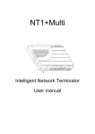
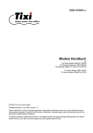
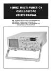
It depends on the access facilities of your Internet service provider (ISP) or
Point-of-presence (POP) which one you may use (see figure 1).
async
V.24
PC with
Online Software
Pocket
ISDN-TA
ISDN
Basic
Rate
Access
ISDN network
Online (POP) Access Server
CompuServe Access Server
T-Online Host System
Figure 1: Usage of the Pocket ISDN-TA to access an Online Service
2
1.3
Operating manual Pocket ISDN-TA
AOL/CompuServe Access
AOL/CompuServe is accessed via ISDN by the protocol V.120 or X.75 (see picture
1). It depends on the access facilities of your AOL/CompuServe access point
which one you have to use (see figure 1). The increasingly common protocol used
is X.75.
1.4
T-Online
T-Online (German Online Service) is accessed via ISDN by the protocol T.70NL /
X.75 or synchronous PPP (see figure 1).
1.5
Remote LAN Access
To access a LAN remotely via ISDN you have to choose the appropriate protocol
that is used by the ISDN router on the LAN.
1.6
Service
INSYS has installed a Windows-NT-Server just for test purposes. The Server supports
the RAS (Remote Access Service) with full 64 kbps in one single B channel. The RAS
service gives the possibility to connect PC's using Windows-2000/NT or
Windows9x/ME with each other.
You have to install on your Windows PC the Dialup Networking – see the Windows
helpdesk how to install and use. Please select at your machine the protocol stack
TCP/IP.
The POCKET ISDN-TA has to be set to HDLC async to sync (like the configuration for
Internet access) by selecting the Modem “TA Internet PPP”.
The ISDN number is ++49 40 89088 328.
Please use the username "guest" and password "guest".
1.7
License
The POCKET ISDN-TA has the following license number for the connection to the
PSTN according to CTR3/A1:
CE-0682 X
for Europe (EC), Switzerland, Norway.
POCKET ISDN-TA is conforming to the European safety requirements IEC 60 950.
Please use only the delivered power supply or an original replacement from INSYS.
Connect the POCKET ISDN-TA only to the S0-interfaces with SELV (Safety Extra Low
Voltage) related to EN60950.
The POCKET ISDN-TA is conforming to the European rules of EMC. EN50081-1, here
EN55022 Class B, for electromagnetic field emission and EN50082-1 for immunity
against electromagnetic interference.
Installation
3
2
Installation
2.1
Contents
This packet contains the following items:
•
•
•
•
•
•
ISDN Terminal adapter POCKET ISDN-TA in desktop box
Mains plug power supply adapter
ISDN interface cable
DTE interface serial cable
Floppy disk with installation software Windows9x/ME/2000 and WindowsNT
This user manual
2.2
•
Installation procedure
Connect the serial port (DTE) of the POCKET ISDN-TA to the serial port
(COM-port) of the PC by using the supported DTE interface serial cable.
Please make sure that the COM-port of the PC is not used for other purposes
or by other communication programs.
Connect the ISDN port of the POCKET ISDN-TA to the basic rate interface
(BRI) of the ISDN using the delivered ISDN cable.
Connect the power supply with the POCKET ISDN-TA and plug it into mains.
•
•
Please reference to page 6 for selecting the correct plug for interfacing.
Now the power-up sequence described in chapter 0 should appear.
The POCKET ISDN-TA is now ready for use; please refer to the next chapter for the
configuration to use the PC together with the POCKET ISDN-TA.
2.3
Windows 9x/ME/2000 Software Installation
This chapter describes the installation, configuration and usage of the POCKET
ISDN-TA for the operating system Windows 9x/ME/2000.
The following components will be installed:
•
•
•
Modem driver into the modem list
CAPI 2.0 driver
Configuration program
4
Operating manual Pocket ISDN-TA
2.3.1 Preparation (Windows9x/ME/2000)
Please check the following requirements before installing the software for
Windows9x/ME/2000:
•
•
•
•
•
PC-System with connected POCKET ISDN-TA.
Access to a 3,5“ Floppy disk drive and hard disk
Installed Microsoft Windows 9x/ME/2000 operation system
Windows 9x CD-ROM (Installation disks) (typically not required for ME/2000)
Installation disk SW-TA/Win9x/WinNT4.0/Win2000
2.3.2 Installation (Windows9x/ME/2000)
1.
2.
When the POCKET ISDN-TA is connected and power up while booting your
PC with Windows9x/ME/2000, the Plug and Play feature of the POCKET ISDNTA will get active, so Windows9x/ME/2000 will request an installation disk.
If you want to install manually the POCKET ISDN-TA driver, execute the
program SETUPTA.EXE from the installation disk. This program leads you
through the installation.
At the end of the installation you will get information about the installed
software and modem types.
The configuration of the POCKET ISDN-TA will be described in the following
section. You can skip the configuration of the POCKET ISDN-TA now, if
information is missing. The configuration can be done later by using the ISDN
configuration generator.
The installation program creates in addition a program folder with program
icons.
The ISDN Configuration Generator is the configuration program for the
POCKET ISDN-TA.
The file Readme shows actual information and changes of the product
release.
The Patch icons add the POCKET ISDN-TA to the modem list of the
software for the online service. Before configuring and using the online
software (after installation) you have to execute the Patch ICON to add
the POCKET ISDN-TA modem to the modem list of the online application.
After making the patch please use one of the following POCKET ISDN-TA
modems (see also page 9):
America Online: use TA X.75
T-Online Patch:
use TA sync PPP
Using the program Uninstall Shield you can uninstall the actual software
and delete the POCKET ISDN-TA modems from the modem list.
Installation
3.
5
Please continue from this point with the configuration as described in the
section Configuration.
2.3.3 Uninstallation
If you want to delete the software of the POCKET ISDN-TA from your hard disk,
please start the program UnInstallShield from the program folder POCKET ISDN-TA.
2.4
Windows NT 4.0 Software Installation
This chapter describes the installation, configuration and usage of the POCKET
ISDN-TA for the operating system Windows NT 4.0.
The following components will be installed:
•
•
•
Modem driver into the modem list
CAPI 2.0 driver
Configuration program
2.4.1 Preparation (WindowsNT4.0)
Please check the following requirements before installing the software for
WindowsNT4.0:
•
•
•
•
•
PC-System with connected POCKET ISDN-TA.
Access to a 3,5“ Floppy disk drive and hard disk
Installed Microsoft Windows NT operation system
Windows NT4.0 CD-ROM (Installation disks)
Installation disk SW-TA/Win9x/WinNT4.0/Win2000
2.4.2 Installation (WindowsNT4.0)
1.
2.
3.
4.
Execute the program SETUPTA.EXE from the installation disk. This program
leads you through the installation.
At the end of the installation you will get information about the installed
software and modem types.
The configuration of the POCKET ISDN-TA will be described in the following
section. You can skip the configuration of the POCKET ISDN-TA now, if
information is missing. The configuration can be done later by using the
POCKET ISDN-TA ISDN Configurator.
Restart Windows to activate new settings.
Now you have to add new Modems manually. Please go to
START -> SETTINGS -> CONTROL PANEL -> MODEMS
Select ADD and activate the button "Don’t detect my modem, I will select it
from a list".
Please choose via the DISKETTE button the path to the POCKET ISDN-TA
installation disk and open the file "mdmstdaa.inf".
You can select the following POCKET ISDN-TA modems:
6
5.
2.5
Operating manual Pocket ISDN-TA
TA Internet PPP
TA Internet ML-PPP
TA T.70-BTX
TA V.120
TA X.75
Please note, that every modem has to be installed separately.
Select the used COM port and finish to end the installation procedure.
Configuration
Using the ISDN TA Configurator the configuration parameter of the POCKET ISDN-TA
will be set up. If you don’t know the correct parameter please contact the
provider of your ISDN basic rate interface (telephone company).
Please make sure, the POCKET ISDN-TA is connected to the serial interface and
powered.
After providing the settings you can leave the configurator. The POCKET ISDN-TA is
now ready to be used with Modem applications (i.e. Microsoft Dial-Up Networking)
or CAPI compatible application programs.
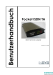
Displays and control elements
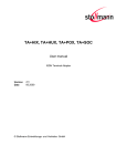
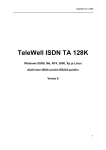
At the back of the POCKET ISDN-TA you will find the connectors for the following
devices:
Fig. 2: Back view of the desktop model POCKET ISDN-TA
PWR:
external power supply
S0-Bus:
ISDN interface.
RS232:
V.24 interface for DTE, i.e. a PC
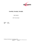
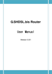
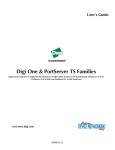
You can control the status of the POCKET ISDN-TA via 8 LEDs at the front side.
Fig. 3: Front view of the desktop model POCKET ISDN-TA
Installation
7
The 4 LEDs at the right show the status of the serial interface to the PC:
R:
shows activity of receiving data from the POCKET ISDN-TA and ISDN
line
T:
shows activity of transmitted data from the terminal
DTR : shows the status of DTR line, i.e. the terminal is trying to connect via
the POCKET ISDN-TA
DCD : represents the status of the DCD line (V.24); shows normally the
connection to an access server.
Both LEDs, B1 and B2, show the connection state of the ISDN B channels:
If ON this B channel is occupied due to an incoming or outgoing connection (data
or voice).
Both of the LEDs, L1 and L2, show the overall status of the POCKET ISDN-TA in coded
form. The following list describes the view for an error free power on sequence of
the POCKET ISDN-TA.
Status
L1
1.
Power-On-Phase, wait
2.
3.
Active phase, ISDN ok
Connected, ISDN data
connection established
LED Legend:
⊗
Θ
O
L2
⊗
⊗
Θ
O
⊗
⊗
On
Continuously blinking
Off
A complete list you can find in the appendix "LED displays"
(about 2 sec)
8
3
Operating manual Pocket ISDN-TA
Using the POCKET ISDN-TA with Application Software
To use the POCKET ISDN-TA with different application software and access points
you have to look for the following items:
•
Usually you need a contract with the service provider. They can help
you to get an appropriate application program to run on a PC.
•
The service provider will also supply you with the ISDN access number
to call (has to be entered in the application program).
•
The TAs parameter must fit the characteristics of the access point
which be recommended in the next chapters.
3.1
Configuration for Internet
To access the Internet via ISDN you have to have a contract with an Internet
service provider (ISP) who runs an ISDN access. To configure the POCKET ISDN-TA
you need the following information from the ISP:
•
ISDN access number (to be entered at the PC program)
•
Layer two protocol, usually the protocol PPP by selecting Modem
POCKET ISDN-TA Internet PPP.
•
Access protocol (to be entered at the PC system software or Internet
software)
To configure the Internet access software on the PC it may be necessary that you
need some additional information like TCP/IP address, user name, password etc.
Please refer to the software manual.
3.1.1 Configuration under Windows 9x/ME/2000
The configuration of the POCKET ISDN-TA can be dependent of the type of access
the Internet provider is supporting. The following types of access are mostly used
for public ISDN access.
• HDLC async to sync conversion
This protocol has to be set up, if the service provider uses an access point
where the protocol PPP is running.
Please get more information from your Internet provider if necessary.
Using the POCKET ISDN-TA with Application Software
3.2
9
Configuration for AOL/CompuServe
You need a contract with AOL/CompuServe to access the AOL/CompuServe
network via ISDN. To configure the POCKET ISDN-TA you need the following
information from AOL/CompuServe:
•
ISDN access number
•
Layer two protocol, usually the protocol-type X.75 by selecting
Modem POCKET ISDN-TA X.75. Some accesses still use B channel
protocol V.120 (select Modem TA V.120).
How to select the modem see also page 4.
You can use a CompuServe access by running the CIM software package. For
AOL use the AOL software.
3.3
Configuration for T-Online (Germany only)
To use the T-Online service via ISDN you have to have a contract for a T-Online
access. For configuration you have to set up the following parameter:
•
ISDN access number, "01910" for a basic rate access.
•
The protocol T.70 by selecting Modem TA T-Online.
•
Select the appropriate access type in your T-Online access software
(COM port)
Alternatively since summer 1997 another access point for T-Online has been
created (the latest T-Online software package has to be used):
•
ISDN access number, "0191011" for a basic rate access.
•
The protocol PPP by selecting Modem TA HDLC-PPP.
10
4
Operating manual Pocket ISDN-TA
Configuring the POCKET ISDN-TA
The settings of the POCKET ISDN-TA for the V.24 interface and the S0 interface are
called configuration. The POCKET ISDN-TA is delivered with a set of pre-set values.
In the following section it will be shown how, by using the configuration
commands, you can examine the configuration of the POCKET ISDN-TA and if
necessary change it. The values can be stored in non volatile memory; this means
they´ll remain unchanged even if the power supply is disconnected.
You can configure the POCKET ISDN-TA in the following ways:
• by using the AT command set entered by the locally connected PC.
• by using TA configuration commands entered by the locally connected PC.
• by using TA configuration commands entered via the ISDN line (remote
configuration).
Normally the configuration via AT commands is sufficient.
The latter case are for more sophisticated configuration and described in the
chapter TA+Configurator command set
4.1
AT command set
All parameter can be changed by using an extended AT command set described
in this chapter.
Please check if the factory setting will fit with your environment. The factory setting
is described (highlighted) in the parameter list shown in chapter "AT command set"
(see below).
If you want another configuration as set in the factory default setting, please do
the following steps:
•
•
•
•
•
•
Connect the POCKET ISDN-TA to ISDN interface
Connect the PC s com-port to the DTE interface of the POCKET ISDN-TA.
Connect the power supply to the mains socket.
Start a terminal emulation on your PC, please verify that the baudrate
setting of the terminal emulation fits those of the POCKET ISDN-TA.
Set up the parameter of the POCKET ISDN-TA from the terminal emulation
and save the parameter using the AT command set.
Example:
To change the used B channel protocol to X.75 please enter the
following commands:
ATB10<↵>
(set protocol to X.75)
AT&W<↵>
(save the new configuration)
Leave your terminal emulation and start your application program.
With the exception of the command A/ (Repeat command) all commands begin
Configuring the POCKET ISDN-TA
11
with the prefix AT and are terminated with <↵>. Corrections in a command line are
done with <BACKSPACE>. A command line has a maximum of 80 characters. The
command line is automatically cancelled by longer input. Blanks are ignored,
capital/small letters are not significant.
The parameter settings of the POCKET ISDN-TA obtained when using the AT
commands can be permanently stored (AT&W) and are not lost by resetting or by
leaving the AT command mode.
To enter the AT command mode during an active data connection you must use
the following sequence ("Escape sequence"):
at least 1 sec pause <+><+><+> 1 sec pause
The time gap between all three plus signs may not exceed 1 sec.
The escape sequence is transmitted transparent to the remote device.
Supported commands:
A/
Repeat last command line
This command repeats the commands of the last entered command line.
Note: No prefix AT is required.
A/
A
Accept incoming call
Using this command you can accept an incoming call, if automatic call
acceptance is not set (Register S0 = 0). An incoming call is displayed by the
message “RING“ or the code “2“.
Must be the last command in an AT command line.
ATA[//<UUS1data>]
UUS1data
transmitted data with UUS1 signalling
B
B channel protocol
Transmission protocol for data communication in the B channel.
ATB0 : V.110 asynchronous
(i.e. for BBS access)
ATB3 : HDLC async to sync conversion (PPP asynchronous, single link PPP,
default)
(i.e. for Internet / dial-up network
access)
ATB4 : HDLC transparent (octets are packed into HDLC frames)
ATB5 : Byte transparent (raw B channel data)
ATB10 : X.75-NL
(i.e. for BBS access)
ATB13 : V.120
(for AOL/CompuServe access)
ATB20 : X.31 B channel (X.25 B channel, option)
12
Operating manual Pocket ISDN-TA
ATB21 : X.31 D channel (Option)
ATB22 : T.70-NL-CEPT
ATB23 : T.90-NL
ATB31 : Multilink PPP (ML-PPP)
%B
(for T-Online (videotex) access)
Set local baudrate
Sets the local baudrate of the POCKET ISDN-TA to the desired value (fix value) or to
autodetection. When autodetection is set, the POCKET ISDN-TA will recognize the
desired baudrate with every newly entered AT command by the terminal
equipment (PC). With all other settings the PC must use the same baudrate.
Must be the last command in an AT command line.
AT%B0
Automatic local baudrate detection enabled (autobauding,
default)
AT%B1
Local baudrate set to 1200 bit/s
AT%B2
Local baudrate set to 2400 bit/s
AT%B3
Local baudrate set to 4800 bit/s
AT%B4
Local baudrate set to 9600 bit/s
AT%B5
Local baudrate set to 19200 bit/s
AT%B6
Local baudrate set to 38400 bit/s
AT%B7
Local baudrate set to 57600 bit/s
AT%B8
Local baudrate set to 115200 bit/s
AT%B9
Local baudrate set to 230400 bit/s
Note: If autobauding is selected (default) and after powering on the TA+POC no
AT command is entered, a response from the POCKET ISDN-TA (i.e. RING) will
be sent with the baudrate 115200 bit/s.
Configuring the POCKET ISDN-TA
CONF
13
Enter TA+Configurator
Enters directly into the TA+Configurator, the configuration prompt "#" will be
displayed. Leave the TA+Configurator with the command "quit".
ATCONF
&C
DCD control
Selects the behavior of the DCD control line from the POCKET ISDN-TA.
AT&C
TA control line DCD is always ON
AT&C1
DCD ON indicates ISDN connection is established and
synchronized (default)
#C
Received bearer service
Shows the bearer service that is received with an incoming call in hexadecimal
coding hbhb.
The value for hbhb (word) is the CIP value as defined in the CAPI 2.0 specification,
, also to be found via INSYS URL http:\\www.insys-tec.de.
AT#C
#C1=hbhb
Select bearer service outgoing
Selects the bearer service that will be sent with an outgoing call
The value for hbhb (word) is the CIP value as defined in the CAPI 2.0 specification
(default 0000).
Example: an outgoing call as a voice call: AT#C1=0004.
#C2=hbhbhbhb
Select bearer service incoming
Selects the bearer services that can be accepted with an incoming call. The
definition of hbhbhbhb (double word) is the CIP mask as defined in the CAPI 2.0
specification (default 00000004).
Example:
AT#C2=00030012 : Accept analogue incoming calls
AT#C2=00000001 : Accept all incoming calls.
Note: Before issuing an outgoing call the command AT#C1 has to be set.
To use the predefined services please setup factory defaults (AT&F).
14
Operating manual Pocket ISDN-TA
D
Initiate outgoing call
Dials the number (D for Dial). The dial modifier "W", ">", "T", ";", "@" can be freely
inserted in the dial string; they have no influence on the dial procedure of the TA.
Must be the last command in AT command line.
Any character input while the POCKET ISDN-TA is dialing will cancel the dialing
procedure.
ATD<CALLEDnumber>[/<subaddr>][//<UUS1data>]
[,X[Pxxx-][R ][N<nuipwd> ][G<cug> ]<X25number>][D<userdata>]]
CALLEDnumber: ISDN call number for a dialled B channel connection or
X.25 number for X.31 D channel
subaddr
dialled subaddress
UUS1data transmitted data with UUS1 signalling
P:
use packetsize xxx for X.25 connection
R:
request the facility reverse charging
G:
access to X.25 closed user group
O:
Outgoing call from X.25 closed user group
N:
use NUI and password with call setup
allowed chars: a-z, A-Z, 0-9.
(overrides setting of nui configuration command)
X25number: dialled X.25 call number (X.25 B channel only)
D:
separator for userdata: "D" or ",": user data without protocol ID
"P": user data with protocol ID (“01000000“)
ATDL
ATDS=n
Dial the last dialled number
Dial number n from stored telephone number list (n = 1..3)
(See command AT&Z to store numbers)
ATD<CALLEDnumber>e Make a call for remote management (see note).
Note1:
To setup the own subaddress see configuration command sub.
Note1:
Adding an "e" to CALLEDnumber indicates that a connection to the
internal remote access of a POCKET ISDN-TA shall be performed, the
protocol X.75 (ATB10) has to be used.
Configuring the POCKET ISDN-TA
&D
15
DTR control
Selects the behavior of the POCKET ISDN-TA, when the DTE control line DTR
changes from ON to OFF.
AT&D
DTE control line DTR setting is ignored
AT&D2
DTE control line DTR is evaluated: dropping the DTR line by the
DTE will disconnect an existing ISDN connection (default).
An incoming call will accepted only with DTR active.
E
Local echo
Selects the local echo in command mode.
ATE
No local echo
ATE1
Local echo on in command phase (default)
&F
Load factory defaults
Factory default will be loaded, ISDN protocol setting and msn´s will not be
overwritten. (for storing in non volatile memory please use the command AT&W).
AT&F
setup all parameter concerning data port
AT&F1 setup all parameter including ISDN protocols, msn settings and
passwords.
H
Disconnect
Disconnects existing ISDN data connection, after issuing the Escape sequence
(see page 11).
ATH[//<UUS1data>]
UUS1data
transmitted data with UUS1 signalling
I
Display version information
Displays different information about version number and settings:
ATI
Returns the "Modem"-type; name of the terminal adapter (“TA“)
ATI1 Returns internal checksum (“64“)
ATI2 Returns “OK“
ATI3 Returns version string: "TA5.xy.z0"
ATI4 Returns manufacturers name: "INSYS MICROELECTRONICS GmbH"
ATI5 Returns ISDN selected protocol: "0 - DSS1"
ATI6 Returns copyright string: "(c) Copyright INSYS MICROELECTRONICS
GmbH"
16
Operating manual Pocket ISDN-TA
ATI7
ATI8
ATI9
ATI77
ATI99
&K
Returns “OK“
Returns “ERROR”
Returns plug and play ID string
Returns Bootloader version string
Returns software creation date
Flowcontrol
Selects the flow control behavior of the POCKET ISDN-TA while in data
communication phase.
AT&K No local flow control between the DTE and TA is used
AT&K3 Local flow control is set to hardware handshake RTS/CTS (default)
AT&K4 Local flow control is set to software handshake XON/XOFF
#M
Received CLID
Shows the called line identification (CLID) that is received with an incoming call –
this is the number of the called party addressed on the local S-bus (selected msn).
AT#M
N
Set line baudrate V.110
Selects the line baudrate of the POCKET ISDN-TA to the desired value (only valid for
B channel protocol V.110 asynchronous).
ATN0 Line baudrate automatic set (equals to local baudrate or less)
ATN1 Line baudrate set to 1200 bit/s
ATN2 Line baudrate set to 2400 bit/s
ATN3 Line baudrate set to 4800 bit/s
ATN4 Line baudrate set to 9600 bit/s
ATN5 Line baudrate set to 19200 bit/s
Configuring the POCKET ISDN-TA
O
17
Return to online state
If the POCKET ISDN-TA is in command mode after issuing an escape sequence out
of an existing connection, ATO brings the POCKET ISDN-TA back to data phase.
Must be the last command in AT command line.
ATO
#O
Received CLIP
Shows the calling line identification (CLIP) that is received with an incoming call –
number of the calling party.
AT#O
Q
Suppress results
With this command result codes or messages can be suppressed.
ATQ
Returns status - codes after command input (default)
ATQ1
No result codes are returned
&R
CTS control
Selects the behavior of the CTS control line from the POCKET ISDN-TA.
AT&R
TA control line CTS is following all changes of RTS
AT&R1CTS is always ON (default)
#R
Handle incoming calls
Selects the behavior of the POCKET ISDN-TA when an incoming call is received.
When set, all incoming calls are ignored independendent of all other settings.
AT#R
AT#R1
Disable automatic reject of all incoming calls (default)
Enable automatic reject of all incoming calls
18
Operating manual Pocket ISDN-TA
S
Display and set internal S register
ATSnn?
ATSnn=xx
&S
Show actual values (decimal) of selected register nn
Set selected register nn to the decimal value xx.
DSR control
Selects the behavior of the DSR control line from the POCKET ISDN-TA.
AT&S
TA control line DSR is always ON (default)
AT&S1 DSR ON indicates ISDN connection is established and synchronized
V
Result format
ATV
ATV1
&V
Display configuration
AT&V
AT&V1
W
Displays the actual configuration of AT command setting
including stored ISDN numbers
Displays the actual configuration of extended AT command
setting
Extended result codes
ATW
ATW1
&W
Result is presented as numbers (followed by <↵>)
Result is presented as text (default)
Result is presented with extended result codes
Result is presented with extended result codes
RING and CONNECT including ISDN address, all others include
error causes.
Message RINGING will be displayed.
Store active configuration
The active configuration will be stored in non volatile memory.
AT&W
Configuring the POCKET ISDN-TA
X
19
Reduce result messages
Reduces the number of result messages after trying to set up a connection
ATX0 "CONNECT" only (without line speed)
ATX1 "CONNECT" with line speed, "BUSY", "NO DIALTONE" not used
ATX2 "CONNECT" with line speed, "BUSY" not used
ATX3 "CONNECT" with line speed, "NO DIALTONE" not used
ATX4 "CONNECT" with line speed, all messages used (default).
Z
Load stored settings
The active configuration will be reset to the stored configuration.
Must be the last command in an AT command line.
ATZ
&Z
Store call-number
Stores dialing number nn as entry number x into the telephone list (x = 1..3).
AT&Zx=nn set entry number x to dialling number nn
AT&Zx=erases entry number x.
AT&Zx shows entries number x.
AT&Z
show all entries.
Note: Refer to TA+Configurator command catab for more information.
See command ATDS for using.
#Z
Define own msn
Defines the msn nn (multiple subscriber number) for the data port.
If the number is set to “*“ (default), all incoming calls are acceptable.
The msn can be displayed by command AT#H or AT&V.
AT#Z=nn
set msn to nn
AT#Z
shows currently set msn number.
The msn is automatically stored to non volatile ram (without issuing command
AT&W).
Note: If 1TR6 D channel protocol is selected, only one or the last digit is valid.
20
**DBITS
Operating manual Pocket ISDN-TA
Number of data bits x asynchronous chars (7,8)
Number of data bits x for asynchronous character (7,default: 8)
AT**DBITS=x
**PRTY
Parity asynchronous chars
Selects the parity for asynchronous characters.
0: no parity; 1: even parity; 2: odd parity
AT**PRTY=0
No parity (default)
AT**PRTY=1
Even parity
AT**PRTY=2
Odd parity
4.1.1 ISDN specific AT commands
Setting up special ISDN parameter:
(only one command is allowed per AT command)
**BSIZE
Set B channel block size
Defines the maximum length x of a data block transmitted or received in B
channel (default: BSIZE = 2048).
AT**BSIZE=x
Note: The value will be changed by setting the B channel protocol (ATBx).
**LLC
Set low layer compatibility (LLC)
Defines the LLC value for outgoing calls in hexadecimal format. In some situation a
specific LLC value is required to pass detailed information about the used B
channel protocol to the called party. This can be done by setting the LLC to a fix
value.
An empty parameter has to be entered by "-" (default: LLC is empty).
Example:
Deleting of LLC-value: AT**LLC=-<↵>
Entering a new LLC:
AT**LLC=8890<↵>
Note: The value will be changed by setting the B channel protocol (ATBx).
Configuring the POCKET ISDN-TA
**DTE
21
Set B channel Layer 2 address
Selects the Layer 2 link addresses. Only valid for protocols that are HDLC based
(X.75, LAPB).
AT**DTE=0 Calling side reacts as DTE,
called side reacts as DCE (default, X.75 standard)
AT**DTE=1 TA reacts as DTE (own adr = 01)
AT**DTE=3 TA reacts as DCE (own adr = 03)
Note: The value will be changed by setting the B channel protocol (ATBx).
**ISDN
Select D channel protocol
Selects ISDN D channel protocol to the ISDN line. The protocol must fit the protocol
running on the ISDN line otherwise a connection cannot be set up.
Note: after changing and storing the ISDN protocol the POCKET ISDN-TA has to be
reset by powering it off and on (alternately you can use the command
AT&W**RESET).
AT**ISDN=0
Select DSS1 (Euro-ISDN) (default)
AT**ISDN=5
AT**ISDN=6
AT**ISDN=7
AT**ISDN=8
AT**ISDN
AT**?ISDN
**K
Select Bellcore National ISDN-1/2 (USA) (Option)
Select NTT INS-NET (Japan)
(Option)
Select AT&T 5ESS (USA)
(Option)
Select VN-4 (France)
(Option)
Show selected ISDN protocol
Show available ISDN protocols
Set Layer 2 windowsize
Sets windowsize x layer 2 protocol B channel:
x = 1 ..7, default: 7
AT**K=x
The default value is dependent of the selected B channel protocol.
**PTP
Set ISDN interface type
AT**PTP=0
AT**PTP=1
select multipoint mode (to connect ISDN terminals,
default)
select point to point mode (to connect ISDN switching
systems)
22
Operating manual Pocket ISDN-TA
**RPWD
Password remote configuration
Sets password for remote configuration to nn (1..32 chars)
AT**RPWD=nn
Default: empty.
**SPID1, SPID2
Set SPID
(Option)
For ISDN lines in the U.S. you have to set the SPID. You get it from your ISDN
provider.
AT**SPID1=xxxx
Set SPID 1
AT**SPID2=xxxx
Set SPID 2
**<cmd>
Execute configuration command
Executes one configuration command, for definition of commands.
AT**<cmd>
4.1.2 AT command S register set
S0
S1
S2
S3
S4
S5
S7
S9
S16
S90
S91
0: No automatic call acceptance, acceptance of an incoming call is
controlled by the data terminal (command ATA after RING)
1: Immediate call acceptance by the terminal adapter (default)
2..n: Call acceptance through the terminal adapter after n "RING"
messages.
Note: The time between two ring messages can be configured using
the TA-configuration command “ringtimer“ (default = 5 sec.)
Ring Counter (read only)
Escape Character (default = 43h)
Carriage Return Character (default = 0Dh)
Line Feed Character (default = 0Ah)
Backspace Character (default = 1Ah)
Wait time for Carrier (sec) (default = 30 sec)
Enable PNP functionality for Windows95 (default=1, enabled)
Last occurred CAPI/ISDN error cause
Last incoming ISDN calling number (CLIP)
0: default
1: all unknown AT commands will be answered with OK.
2: Windows 2000 compatibility: some AT commands will be answered
with OK (see list below), unknown AT commands will be answered with
OK.
Windows2000 AT command set change:
Configuring the POCKET ISDN-TA
ATNxxx
ATBxxx
AT\Nxxx
23
all commands ATNxxx will respond OK without any
functionality behind it. V.110 baudrates can be set
with AT**BRN.
All commands ATBxxx will respond OK without any
functionality behind it. The B-channel protocol
settings can be set with AT**PROT.
All commands AT\Nxxx will respond OK without any
functionality behind it. The B-channel protocol
settings can be set with AT**PROT.
4.1.3 AT result codes
Result codes (numerical and verbose):
Code
Text
Meaning
0
OK
Command completed
1
CONNECT <rn>
Connection established
(rn = call number of remote site)
2
RING <rn>
Indicates an incoming call
(SETUP
received)
3
NO CARRIER <xx>
No synchronization (xx = ISDN error cause)
4
ERROR
Illegal command or error that can not be
indicated otherwise
5
CONNECT 1200 <rn>
Connection, line speed 1.2 kbps (V.110)
6
NO DIALTONE <xx>
No access to ISDN network (xx = ISDN error)
7
BUSY <xx>
Number engaged (xx = ISDN error cause)
8
NO ANSWER <xx>
No connection; called number can not be
reached (xx = ISDN error cause)
10
CONNECT 2400 <rn>
Connection, line speed 2.4 kbps (V.110)
11
CONNECT 4800 <rn>
Connection, line speed 4.8 kbps (V.110)
12
CONNECT 9600 <rn>
Connection, line speed 9.6 kbps (V.110)
16
CONNECT 19200 <rn> Connection, line speed 19.2 kbps (V.110)
19
CONNECT 64000 <rn> Connection, line speed 64 kbps
RINGING <rn>
Outgoing call is ringing at called site
24
Operating manual Pocket ISDN-TA
Call number display:
<rn> = call number of remote site
In AT command mode, call number display (does not belong to the AT command
standard) can be turned on by issuing the command ATV2 or ATV3. If turned on,
the call number of the caller is shown with the Connect- or Ring-message (in
pointed brackets), depending on the signaling in D-channel.
If the POCKET ISDN-TA is used at the public network then the call number of the
remote site (including area code) is displayed.
Example:
CONNECT 64000 <040890880>
Error cause display:
<xx> = ISDN release (error) cause, hexadecimal
Example:
NO CARRIER <#34F0>
In AT command mode, error cause display (does not belong to the AT command
standard) can be turned on by issuing the command ATV2 or ATV3. The shown
error causes use the coding defined by the CAPI definition. ISDN error causes from
the ISDN network are always coded as 34xxH, where xx represents the
hexadecimal version of the ISDN error cause (see page 30). All other causes are
CAPI error causes (see page 32).
4.2
ISDN access control
Using these commands you can setup a table, to allow only dedicated callers to
get a connection to the POCKET ISDN-TA.
If this list is empty (default) or one entry is set to star (*), any incoming call is
allowed.
Every incoming call that does not fit to one of the entries of acctab will be
ignored. The received calling party number is compared to every entry beginning
at the last digit and is stopped when the shorter number is completely compared.
acctabx nn/ss
acctabx acctabx *
acctabx
acctab
set entry number x to ISDN number nn and subaddress ss
clear entry number x
allows all incoming calls to be accepted
shows entry number x
shows all entries
Maximum number of entries = 5; x = 1..5
Maximum length of ISDN number = 20 digits
Maximum length of subaddress = 20 digits
The ISDN number nn can contain wildcards:
* : represents one or more digits
? : represents exactly one digit
Configuring the POCKET ISDN-TA
25
Note: If a subaddress is set, the received calling subaddress must be identical to
the subaddress that is set.
Examples:
acctab1 1234567890
acctab2 *456*
acctab3 ?2345678??
acctab2 *1234/987
acctab3 *
acctab3 -
accept only specified number
accept all numbers with 456 somewhere in the
middle
accept all number with 2345678 in the middle
peceeded by one digit and followed by two digits.
accept all numbers that end with 1234 and
have the subaddress 987
accept all incoming calls without subaddress
clear entry no. 3
Note:
If you are not sure, in which format the calling number will be presented with
an incoming call, please use the command ATV2 to see the the format of
the calling number in the RING message. This number can be entered into
the acctab.
4.3 User to User Signalling UUS1
With outgoing and incoming calls the transmission of User-to-User-Data (UUS1data) can be performed using the ISDN supplementary service UUS1. The UUS1data are transmitted transparently from the calling party to the called party
before the B channel connection is fully established.
Please note, that this ISDN service typically has to be enabled by the ISDN service
provider and may be charged additionally.
See the command ATD in AT command set:
Example:
ATDisdnnumber[//<UUS1-data>]
(PAD:)
X25number[I<ISDNnumber>[//<UUS1data>]]
“//”: separator for UUS1-data
The UUS1-data have a maximum length of 128 Bytes and will be interpreted as
ASCII characters.
Incoming UUS1-data are presented as enhencement to the RING and CONNECT
message.
AT:
RING [<rn>] [//<UUS1-data>]
CONNECT [<rn>] [//<UUS1-data>]
PAD: <X.25addr>I<isdnnumber>[//<UUS1-data>]
COM
Note: The presentation of UUS1-data has to be enabled by command ATW1.
26
Operating manual Pocket ISDN-TA
The data are presented as ASCII characters.
An incoming call can be accepted (S0 register set to 0) by an ATA or rejected by
an ATH combined with the transmission of UUS1-data (AT only):
ATA [//<UUS1-data>]
ATH [//<UUS1-data>]
Examples:
ATD1234567890//userdata#010203*ende
RING //userdata
RING //#01020304
4.4 Subaddressing
With outgoing and incoming calls the transmission of subaddresses can be
performed using the ISDN supplementary service SUB. The subaddress is transmitted
transparently from the calling party to the called party before the B channel
connection is fully established.
Please note, that this ISDN service typically has to be enabled by the ISDN service
provider and may be charged additionally.
The subaddress is separated by an “/“ from the called number.
The functionality Subaddressing can be used with the dialling procedures ATcommand set, PAD X.3 and automatic call.
Examples:
ATDisdnnumber[/subaddr]
isdnnumber
Dialling called party number
subaddr
Called subaddress
RING [<rn>[/subaddr]]
CONNECT [<rn>[/subaddr]]
rn
subaddr
Calling party number
Calling party subaddress
The own subaddress (calling subbaddress) can be setup using the configuration
command sub.
Note: The subaddress can be entered additionally into all tables that contain ISDN
numbers for dialling or checking an ISDN address.
4.5
Using Multilink PPP
Configuring the POCKET ISDN-TA
27
To enable Multilink PPP handling within the POCKET ISDN-TA please enable the B
channel protocol ML-PPP: atb31 rsp. prot = 31.
ML-PPP may be used with different authentification procedures during the call up
of the line. One of these is CHAP. You may enable ML-PPP CHAP by the following
steps:
• Enter “at**chappwd=<password>” to input your password in the POCKET
ISDN-TA.
• Enter “AT&W” to store the setting in the POCKET ISDN-TA.
Afterwards a ML-PPP connection is initially made using CHAP authentification. If
the server does not handle CHAP an automatic fallback to PAP is performed.
You may control the settings by typing “AT&V1”.
Warning: Since the password is shown in plain text it may be disclosed by
unauthorized persons.
4.5.1 Details on Multilink PPP
Currently on INSYS TAs running Multilink PPP (ML-PPP) the following authentication
protocols (AP) are supported:
•
•
•
•
Password Authentication Protocol (PAP)
Challenge Handshake Authentication Protocol (CHAP) with the variants
MD5 according to RFC 1321
Microsoft Chap according to RFC 2433
PAP exchanges the password in clear text format in the B-channel, whereas CHAP
encrypts the password according to the algorithms described in the RFCs
mentioned above. For CHAP the password has to be stored in the POCKET ISDN-TA
in addition to the setting in the Dial-up Network under Windows 95. Under Windows
98/ME/2000 this is not necessary.
The following basic rules apply when the POCKET ISDN-TA is configured to run MLPPP:
1. If the remote side requests (in the Link Control Protocol LCP ConfigRequest) an
AP that the POCKET ISDN-TA can handle, the request is forwarded to local side.
2. If the remote side requests an AP that the POCKET ISDN-TA cannot handle, the
POCKET ISDN-TA proposes the safest protocol depending on its capabilities:
• PAP if no password chappwd is locally stored,
• CHAP/MS-CHAP MD5 if a password chappwd is locally stored.
This step may be repeated a limited number of times only, if this number
exceeds, the POCKET ISDN-TA falls back to single link operation until the next
connection is tried.
28
Operating manual Pocket ISDN-TA
3. Once the local side rejects (with a LCP ConfigNak) an AP that was alternatively
proposed by the POCKET ISDN-TA (see previous rule), the POCKET ISDN-TA falls
back to single link operation until the next connection is tried. Local and remote
side may negotiate any AP they like.
4. At the end of the link setup procedure the negotiated AP is checked and, if
supported, is used for the second link too. If the final AP is not supported the
second link is not established, the POCKET ISDN-TA falls back to single link
operation until the next connection is tried.
Note that some hosts are very strict, e.g. if PAP is proposed by the POCKET ISDN-TA
due to the lack of a locally stored password chappwd they simply hang up the
connection without any chance to negotiate anything else. In these cases the
POCKET ISDN-TA should be configured for single link PPP operation, or,
alternatively, the chappwd should be supplied and stored on the POCKET ISDN-TA.
4.5.2 Call Bumping
A ML-PPP connection uses both B-channels of the S bus. To accept an incoming
call (i.e. for telephony) during a ML-PPP session one B-channel has to be released.
This is called Call Bumping.
To enable Call Bumping proceed as follows:
• Activate call waiting on the S bus. It has to be activated in the ISDN switch and
is a feature of the ISDN line you ordered.
• Open the “properties” of the dial-up link you are using for ML-PPP and
“additional settings”. Input “at**cmlp=1” as an additional parameter.
If there is an incoming call during a ML-PPP session the POCKET ISDN-TA will drop
one B-channel and an ISDN telephone attached to the S bus will be ringing to
accept the call.
4.5.3 Bandwidth on demand ("BOD")
Enabling this feature will cause the TA+PP2 to use the Multilink PPP protocol to
enhance the ISDN throughput using the second B channel automatically:
• if the throughput of the internet connection is higher than a definable value a
second B channel connection will be established automatically and for data
transfer used.
• if the throughput of the internet connection is lower than a definable value the
second B channel connection will be disconnected automatically.
at**bod=0
disable BOD (default)
at**bod=1
enable BOD
at**bodiv=<incrValue>
Throughput level to add 2nd B channel connection
(in kbit/s) (default=40)
at**bodit=<incrTime> duration that bodiv has been reached to add 2nd b
channel (in secs) (default=30)
at**boddv=<decrValue> Throughput level to release 2nd B channel connection
Configuring the POCKET ISDN-TA
29
(in kbit/s) (default=40)
at**boddt=<decrTime>
duration that boddv has been reached to release
2nd b channel (in secs) (default=30)
Note: call bumping ("cmlp") has higher priority than bandwidth on demand.
4.6
Software update
The POCKET ISDN-TA uses a Flash-EPROM to store the software. This software can be
updated from a local connected PC via the COM port.
4.6.1 Software update
Please fulfil the following steps to update the POCKET ISDN-TA:
•
•
•
•
•
•
•
•
Get a new software release for the POCKET ISDN-TA from your supplier and
copy it to your PC.
Start a terminal emulation on your PC with the capability to run an X-MODEM
file transfer (i.e. HyperTerminal).
Enter the AT command “at**flash“.
Wait for end of erasing the Flash-EPROM and the prompt to start your X-MODEM
transfer.
Start the 1kX-MODEM file transfer (send file or upload) by selecting the Transfer /
Send File menu point in your terminal emulation and select the new software.
After completion you will get the information whether the software update
ended successfully or erroneous.
Give the POCKET ISDN-TA about 20 seconds to activate the new software.
Due to new functionality the last stored configuration setting may be lost,
please check before using. To set factory default values please use the
command "at&f1".
30
5
Operating manual Pocket ISDN-TA
Diagnostic and error messages
For the diagnostic of erroneous situations the following functionality is supported.
Please check first the behaviour of LED displays, if an ISDN connection can not be
established. Refer to list of LED displays on page 34.
5.1
Error messages from AT command set
When the extended result messages are selected using the command ATV2 ISDN
error codes are displayed in addition to the standard AT result messages.
ISDN error causes from the ISDN network are always coded as 34xxH, whereas the
last two digits xx represent the ISDN cause in hexadecimal coding. The meaning
can be taken from the following tables ISDN causes (see page 30).
5.2
Table of ISDN causes and their explanation (DSS1)
Cause
Decimal /
Hexadecimal
1 / 0x81
2 / 0x82
3 / 0x83
6 / 0x86
7 / 0x87
16 / 0x90
17 / 0x91
18 / 0x92
19 / 0x93
20 / 0x94
21 / 0x95
22 / 0x96
26 / 0x9A
27 / 0x9B
28 / 0x9C
29 / 0x9D
30 / 0x9E
31 / 0x9F
34 / 0xA2
38 / 0xA6
41 / 0xA9
43 / 0xAB
44 / 0xAC
Meaning
Translation
to AT result
codes
Unallocated (unassigned) number
3
No route to transit network
3
No route to destination
3
Channel unacceptable
6
Call awarded and being delivered in an 6
established channel
Normal clearing
3
User busy
7
No user responding
8
No answer from user (user alerted)
8
No answer from user (device off)
8
Call rejected
8
Number changed
3
Non selected user clearing
3
Destination out of order
8
invalid number format
3
Facility rejected
3
Response to STATUS ENQUIRY
3
Normal disconnect, unspecified
3
No circuit/channel available
7
ISDN network out of order
6
Temporarily failure
6
Access information discarded
6
Requested circuit/channel not available
6
Diagnostic and error messages
Cause
Decimal /
Hexadecimal
46 / 0xAE
47 / 0xAF
49 / 0xB1
50 / 0xB2
53 / 0xB5
55 / 0xB7
57 / 0xB9
58 / 0xBA
63 / 0xBF
65 / 0xC1
66 / 0xC2
69 / 0xC5
70 / 0xC6
79 / 0xCF
81 / 0xD1
82 / 0xD2
83 / 0xD3
84 / 0xD4
85 / 0xD5
86 / 0xD6
87 / 0xD7
88 / 0xD8
90 / 0xDA
91 / 0xDB
95 / 0xDF
96 / 0xE0
97 / 0xE1
98 / 0xE2
99 / 0xE3
100 / 0xE4
101 / 0xE5
102 / 0xE6
103 / 0xE7
31
Meaning
Translation
to AT result
codes
Precedence call blocked
Resource unavailable, unspecified
Quality of service unavailable
Requested facility not subscribed
6
6
3
3
OUTGOING CALLS BARRED WITHIN CUG
INCOMING CALLS BARRED WITHIN CUG
BEARER CAPABILITY NOT AUTHORIZED
3
3
3
Bearer capability not presently available
Service or option not available, unspecified
Bearer capability not implemented
Channel type not implemented
Requested facility not implemented
Only restricted digital information bearer
capability is available
Service
or
option
not
implemented,
unspecified
Invalid call reference value
Identified channel does not exist
A suspended call exists, but this call identity
does not
Call identity in use
No call suspended
Call having the requested call identity has
been cleared
User not member of CUG
Incompatible destination
Non-existent CUG
Invalid transit network selection
Invalid message, unspecified
Mandatory information element missing
Message
type
non-existent
or
not
implemented
Message not compatible with call state or
message
type
non-existent
or
not
implemented
Information element /parameter non-existent
or not implemented
Invalid information element contents
Message not compatible with call state
Recovery on timer expiry
Parameter non-existent or not implemented,
3
3
3
3
3
3
3
3
3
3
3
3
3
3
3
3
3
3
3
3
3
3
3
3
3
32
Operating manual Pocket ISDN-TA
Cause
Decimal /
Hexadecimal
111 / 0xEF
127 / 0xFF
5.3
Meaning
passed on
Protocol error, unspecified
Network interworking error, unspecified
CAPI causes and their explanation
Coding of the CAPI cause in hexadecimal form.
0000
0001
0002
0003
No error
NCPI ignored
Flags ignored
Alert already sent
1001
1002
1003
1004
1005
1006
1007
1008
100a
100b
1101
1102
1103
1104
1105
1106
1107
1108
1109
Too many applications
Logical block size too small
Buffer exceeds 64k
Message buffer size too small
Too many logical connections
Reserved1
Message could not be accepted
Register OS Resource Error
External Equipment not supported
External Equipment only
Bad application ID
Illegal cmd or message length
Message queue full
Message queue empty
Message lost
Unknown notification
Message not accepted
OS Resource Error
CAPI not installed
2001
2002
2003
2004
2005
2006
2007
Bad State
Illegal Identifier
Out of PLCI
Out of NCCI
Out of LISTEN
Out of Fax Resources
Illegal Message Parameters
3001
B1 protocol not supported
Translation
to AT result
codes
6
6
Diagnostic and error messages
33
3002
3003
3004
3005
3006
3007
3008
3009
300a
300b
300c
300d
B2 protocol not supported
B3 protocol not supported
B1 protocol param not supported
B2 protocol param not supported
B3 protocol param not supported
B Prot combination not supported
NCPI not supported
Unknown CIP value
Flags not supported
Facility not supported
Data length not supported
Reset procedure not supported
3301
3302
3303
3304
3311
3312
3313
3314
3315
3316
3317
3318
3319
Layer1 protocol error
Layer2 protocol error, i.e. DTE address not correct, TEI not correct
Layer3 protocol error
Another application got the call
Fax remote station is not fax
Fax training failed
Fax disconnect before transfer
Fax disconnect remote abort
Fax disconnect remote procedure
Fax disconnect local transmitter underrun
Fax disconnect local receiver overflow
Fax disconnect local abort
Fax illegal transmit data
34xx
Error cause from the ISDN line, xx represents the ISDN cause (see
capter 5.2)
34
Operating manual Pocket ISDN-TA
6
A1:
Appendix
Technical data:
One V.24 channel:
functional:
electrical:
mechanical:
V.24
V.28
9 pin DSUB connector (female)
Transmission speeds:
DTE:
B channel:
1200 – 230400 bit/s (asynchronous)
2 x 64000 bit/s (synchronous)
Character representation:
8Bit no Parity, 1 stop bit
7Bit even/odd Parity, 1 stop bit
Character synchronization:
asynchronous
Operating mode:
half duplex or full duplex
ISDN interface:
Basic rate interface according to ITU I.430 (RJ45)
Physical dimensions:
desktop casing: 230 x 50 x 200 mm (WxHxD)
A2:
LED displays
Active states:
L1
⊗
Θ (1x1s)
⊗
⊗
⊗
⊗
L2
Θ (2sec)
O
O
∅
⊕
⊗
Status
Power-On-Phase ; Wait
ISDN not ok
; Check ISDN interface/ -connector
Active phase
; ISDN ok, no ISDN connection established
Call active
; ISDN Connection will be established
Synch active
; Waiting for B channel synchronization
Connected
; Data connection is established
Appendix
35
B1,B2
Status B channels
O
⊗
Error states:
L1
L2
O
Θ
O
Θ
O
O
Θ (nx1s)
Θ
B channel offline
;
B channel online
; ISDN connection established
Status
TA not ok
; Hardware error, TA repair necessary
ISDN not ok
; Check ISDN interface/ -connector
TA not ok
; Hardware error, TA repair necessary
B1, B2 flashing: Bootloader aktive, no operational firmware
programmed. Use command at**flash to
download firmware with 115200 Bd,N81 (see
page 29).
LED Legend:
⊗
∅
⊕
Θ
O
A3:
On
occ
short on, long off Cycle 1 sec
fl
long on, short off Cycle 1 sec
(nxms)
continuous blinking: n times every m seconds
Off
Pinout of the ISDN connector
Pinout of the 8 pin ISDN S-interface connector (RJ45) (ITU I.430/ISO 8877)
Pin
1
2
3
4
5
6
7
8
Signal (S0)
Not connected
Not connected
Tx+ (Transmit +)
Rx+ (Receive +)
Rx- (Receive -)
Tx- (Transmit -)
Not connected
Not connected
36
Operating manual Pocket ISDN-TA
A4:
Pin
Pinout of the V.24/V.28 interface TA (DSUB 9)
V.24/V.28
ITU
I/O
DIN
TEXT
EIA
1
109
M5
DCD
O
Data carrier detect
2
104
D2
RD
O
Receive data
3
103
D1
TD
I
Transmit data
4
108/1
108/2
S1.1
S1.2
DTR
I
Data terminal ready
5
102
E2
GND
---
Signal ground
6
107
M1
DSR
O
Data set ready
7
105
S2
RTS
I
Request to send
8
106
M2
CTS
O
Clear to send
9
125
M3
RI
O
Ring indicator
A5:
Pin
Pinout of the V.24/V.28 interface TA (DSUB 25):
V.24/V.28
ITU
I/O
DIN
TEXT
EIA
1
101
E1
---
Protective ground
2
103
D1
TD
I
Transmit data
3
104
D2
RD
O
Receive data
4
105
S2
RTS
I
5
106
M2
CTS
O
Clear to send
6
107
M1
DSR
O
Data set ready
7
102
E2
---
Signal ground
8
109
M5
DCD
O
Data carrier detect
20
108/1
108/2
S1.1
S1.2
DTR
I
Data terminal ready
22
125
M3
RI
O
Request to send
Ring indicator
Appendix
A6:
37
Cable layout for connection of terminals with 25 pin connectors (male or
female) to a TA
Only the cable with a male plug at the terminal side is shown. The pin
configuration for the female plug is the same.
V.24 device
TA
1
shield *
5
SGND
102
5
2
TD
103
3
3
RD
104
2
4
RTS
105
7
5
CTS
106
8
6
DSR
107
6
20
DTR
108
4
8
DCD
109
1
22
RI
125
9
25 pin jack
Attention:
9 pin jack
allowed cable length < 15m.
for transmission speeds > 19.200 bit/s < 2m.
* necessary if cable length > 2m
38
A7:
Operating manual Pocket ISDN-TA
Cable layout to connect a PC with 9 pin male plug through a serial COMport to a TA
PC
TA
shield *
5
SGND
102
5
3
TD
103
3
2
RD
104
2
7
RTS
105
7
8
CTS
106
8
6
DSR
107
6
4
DTR
108
4
1
DCD
109
1
9
RI
125
9
9 pin jack
Attention:
9 pin jack
allowed cable length < 15m.
for transmission speeds > 19.200 bit/s < 2m.
* necessary if cable length > 2m