1
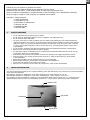
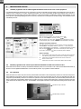
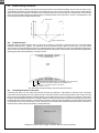
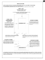
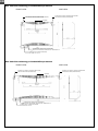
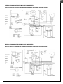
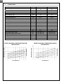
MODEL: DRY 300i & 500i Silver
EN
Thank you for your decision to purchase our device.
Please read this user manual carefully before starting to use the device.
Please keep the instructions of this practical quide in order to get a quick know-how.
We do not take any responsibility or provide warranty in case of damage, loss or damnification caused by
incorrect usage or usage for other purposes, not specified in this manual.
Contents: 1. Safety measures
2. Usage specification
3. Instructions for use
4. Instructions for maintenance
5. Servicing the unit
6. Installation guide
7. Technical data
1.
SAFETY MEASURES
•
•
•
•
•
•
•
•
•
•
•
•
•
2.
Do not manipulate with the device with wet hands.
Do not spray any flammable substances into the equipment; this might lead to fire.
Do not clean the device with water.
The cover of the device is made of rustless steel. For cleaning and polishing the cover without making any
undesired matt blobs on its surface, use grooming and protective articles suitable for rustless metal surfaces.
Apply some drops on a dry and non-fluffy clout and then smoothly wipe it into the surface. After 2 minutes
of drying, wipe it again and polish it using a dry and clean clout (grooming article together with a clout is
in the package).
Do not clean the equipment with aggressive cleaning agents, this might lead to damage or deformations.
Never throw or insert any objects into any tube or opening.
Use this device only for the intended purpose, as described in the attached instructions for use. Do not use
components, which are not recommended.
Never block the air opening of the product. Protect the air openings from clogging by particles, hair etc.
When the device is not running correctly (smoke, smell, etc.), switch off the device by a circuit breaker
in the switchboard.
Repairs and relocations must be performed only by a service technician.
Before cleaning the device, switch off the circuit breaker in the switchboard.
Do not place any objects on the surface of the device.
When you do not intend to use the device for a longer time, switch off the circuit breaker.
USAGE SPECIFICATION
The units are designed especially for use in indoor swimming pools, spas and saunas. They can also be very useful in laundries,
drying rooms and elsewhere.
Microwell DRY 300i Silver is designed for rooms with a swimming pool, which surface is up to 30 m².
Microwell DRY 500i Silver is designed for rooms with a swimming pool, which surface is up to 60 m².
The condition of using the equipment is keeping a room temperature within a range between min. 15 ° C and max. 35 C ° .
Optimal situation occurs when the room temperature is about 2-3 C ° higher than a swimming pool water-temparature.
EXHAUST GRID
UNIT COVER
HYGROSTAT
INTAKE GRID
EN - WALL-MOUNTED SWIMMING POOL DEHUMIDIFIER - OWNER´S & INSTALLATION MANUAL
EN
3.
INSTRUCTIONS FOR USE
3.1.
Humidity regulation with an inbuilt digital humidistat located in the cover of the equipment
The inbuilt humidistat is located in the cover of the device. It reads the humidiy of the incoming air, and depending on the set value,
switches on the compressor. In indoor swimming pool halls, the correct air humidity should range between 55% and 65 %.
Decreasing the level of humidity under the above mentioned range is not desirable, considerating the physiological aspects as well
as the aspects of providing building protection. Moreover, it increases the consumption of electrical energy. The humidistat can be
controlled by the user.
Hygrostat display (front view)
Application mode change
When pressing the
button, the set humidity starts to blink.
When you wish to change the set value, press the
button.
When pressing the
button again,
symbol is displayed, the set value
is memorized and you can read the value of the measured humidity on the display.
Setting programming functions
When the
button is pressed for a longer time than 5 seconds, the following
commands are set: DIF (humidity deviation = hysteresis) → TYP (chosen type =
function of dehumidification or humidification → COR (displayed humidity correction).
When pressing the
button, the values of each mode you wish to change
are set, and by pressing the
button, the following mode is displayed.
Failure reporting
Er1
0-E
S-E
3.2.
Memory failure. Switch off and then switch on again the electrical connection.
If the failure reporting continues, please ask us to change the component.
Sensor failure. The electrical connection of the sensor is broken off.
Please control the cable.
Sensor failure. The sensor is short-circuited. Please control the cable.
Humidity regulation with a back-up mechanical humidistat located in the electronic box
In the electronic box there is a back-up mechanical humidistat, which is set on the value of 70 % RH. This humidistat has a back-up
function in case of digital humidistat failure. User should not perform any regulation of this humidistat.
3.3.
Fan regulation
Under the inside cover of the unit, there is a two-positional fan mode switch. In the first position, the fan runs even if the compressor
of the appliance has stopped: continuous operation of the fan. In the second position, the fan only runs simultaneously with the
compressor: periodical duty of the fan. The continuous operation mode of the fan is preferable, since the humidity reader built in the
device continuously reads humidity, and therefore a greater accuracy is reached. At the same time, continuous operation of the fan
results in better air circulation in the room. The installation work supplier selects the mode of the fan according to the request of the
user.
Continuous duty of the fan
Periodical duty of the fan
Switch of fan operation
EN - WALL-MOUNTED SWIMMING POOL DEHUMIDIFIER - OWNER´S & INSTALLATION MANUAL
EN
3.4.
Compressor regulation
The compressor´s operation starting is for securing its protection, delayed by min. 3 minutes. Depending on the humidity of
environment, it may last even longer. The user must not manipulate with the setting element of a time relay.
4.
MAINTENANCE INSTRUCTIONS
It is necessary to make sure that the intake- and exhaust outlet are not covered. It is forbidden to place towels or clothes on the
exhaust outlet, to dry them. Cleaning the device´s cover can be done only using grooming articles suitable for rustless steel
surfaces. In case there is a water dripping from the equipment, check whether a condensate pipe is not obstructed.
5.
SERVICING THE UNIT
At least once a year, it is necessary to have the unit checked and cleaned by a service specialist. This is necessary in order to secure a
long operational life of the device. Cleaning the interior parts of the device by a user is not recommended, as this may lead to a
damage on the unit. The device contains mobile elements as well as elements under electrical pressure, therefore the interior parts
can be cleaned only by a certified electrician with an appropriate knowlegde of refrigerating technology.
6.
INSTALLATION GUIDE
The unit must be installed in compliance with the local installation and electrical installation regulations !
6.1.
Unit location
To ensure maximum efficiency, it is necessary to install the unit as high above the ground as possible. It is forbidden to install the
unit on the floor. However it is possible to install the unit to a mobile rack, which is an accessory equipment, that can be ordered
additionally. It is essential to ensure good air circulation by allowing at least 150 mm of free space under the unit and at least 200
mm of free space above the unit. For the purpose of maintenance, it is further necessary to allow at least 200 mm of free space on
both sides of the unit.
6.2.
Equipment fixation
The equipment has a self-supporting construction and is very easy to install.
There is an installation bracket included in the equipment accessories, which must be fixed on the wall. The axis of the fixation slots
is 210 mm lower than the top edge of the device. The distance between the fixation slots is 420 mm (DRY 300i Silver) and 360 mm
(DRY 500i Silver). When the bracket is fixed, it is possible to hang up the device without dismounting its cover.
Model DRY 300i Silver
TOP EDGE OF THE DEVICE
SPIRIT LEVEL
BRACKET
FIXATION SLOTS
Model DRY 500i Silver
TOP EDGE OF THE DEVICE
SPIRIT LEVEL
BRACKET
FIXATION SLOTS
6.3.
Dismounting and mounting of the cover
The cover can be dismounted after releasing two screws (DRY 300 Silver) or three screws (DRY 500 Silver) at the bottom of the
device. Release the screws, pull the bottom part of the cover toward yourself and then, by lifting it shortly, rake down the cover from
the rear plate. To mount the cover, carry the procedure out in reverse order.
EN - WALL-MOUNTED SWIMMING POOL DEHUMIDIFIER - OWNER´S & INSTALLATION MANUAL
EN
6.4.
Position assuring of the device
The design of the device enables its safe mounting and proper fixation even if lifted accidentally. There are slots for safety screws
accessible after dismounting a front fibreglass cover, located in the top corners of the rear plate. There is an arrow that indicates
safety screw slots in the rear plate. The safety screw is fixed through a slot in the rear plate into a wall fastener. It prevents the
device from being pulled out and from falling out from a mounting bracket. At the same time, it secures a vertical position of the
device together with a device alignment with a wall.
REAR PLATE
SAFETY SCREW SLOTS
6.5.
Condensate drain
Condensed water is drained from the device by the force of gravity. It is necessary to locate the device in a way that enables
sufficient condensed water gradient. The condensate must be delivered through a siphon into the sewer or into the outside
environmemt. It is strictly forbidden to deliver the condensate back into the swimming pool, as it may be bacterially contaminated.
There is a tube for condensed water delivery located at the bottom of the device, on the left side. This tube must be pluged into a
sewerage pipe with an internal diameter of minimum 16 mm.
CONDENSED WATER DELIVERY (AT THE BOTTOM OF THE DEVICE)
PIPE WITH AN INTERNAL DIAMETER OF MINIMUM 16 mm
POWER SUPPLY (AT THE BOTTOM OF THE DEVICE)
CYSY WIRE 3C x 1,5 mm2
DRY 300i Silver and DRY 500i Silver with connections (front view)
6.6
Connecting the device to the mains
Connecting the device onto the mains and protection securing must satisfy the requirements of relevant norms. Connection
requirements are the following: 220-240 V/50Hz, protection 10A (DRY 300i Silver) and 16A (DRY 500i Silver) with a mains-fuse that
has a current-carrying differential disconnecting capacity, not exceeding 30mA. There is a terminal for connection to the mains,
located on the left hand side of the device. The master switch of the device must be located outside the swimming pool area, it must
be bipolar and with L and N conductors´ disconnecting. The device for disconnecting the appliance from the mains must be inbuilt
to a steady point. There has to be a distance of min. 3 mm between the contacts (when switched off) for all the poles. Connection of
the device to the mains must be performed by a certified electrician.
Preparation of electric power supply, condensate drain and console mounting
EN - WALL-MOUNTED SWIMMING POOL DEHUMIDIFIER - OWNER´S & INSTALLATION MANUAL
EN
DEVICE LOCATION
Device location must be in accordance with HD 384.7.702 S1 and IEC 60364-7-702 standard.
It is recommended to locate the device outside zones 0,1 and 2.
In case the device is located into zones 2 or 1, HD and IEC standards´requirements must be satisfied.
ZONE 1, IPX4
Swimming pools which are not
cleaned by splashing water
In the distance of 1250 - 2000 mm from the swimming pool edge
in accordance with HD and IEC standards
and at least 300 mm above the floor
ZONE 2, IPX2
OUTSIDE THE ZONES
Swimming pools which
are not cleaned by
splashing water
In the distance of 2000 - 3500
mm from the swimming pool
edge. In accordance with HD and
IEC standards and at least 300
mm above the floor, in order to
secure the sufficient aircirculation. It is strictly forbidden
to install the device onto the floor.
At least 1250 mm (i.e. out of the reach of the hand)
from the side edge of the shower cabinet. It cannot
be placed above the shower cabinet.
SWIMMING POOL
In the distance of 1250 mm or less
from the swimming pool edge, the
bottom edge of the device must be
2500 mm above the swimming
pool surface.
At least 1250 mm (i.e. out of the reach of the hand) from
the side edge of the wash basin, in the minimum height of
1200 mm above ground. It cannot be placed above the
wash basin.
OUTSIDE THE ZONES
OUTSIDE THE ZONES
In the distance of at least 1500 mm
from the vertical plane around jumping
platforms, jumping boards and starting
blocks, 2500 mm above the highest
surface, where people are likely to stay.
If the unit is in the distance of less or
equal to 1250 mm horizontally from
the edge of the swimming pool, then
it must be raised up to the height of
2500 mm from the swimming pool
surface; if the pool is embedded
under the floor, then the unit must be
raised up to the height of 2500 mm
from the floor.
SWIMMING POOL
It is inevitable to locate the device outside the zones, where cleaning with splashing water is supposed. Connection of the unit to
the mains and its protection must correspond with the applicable standards. Electrical supply of the unit must be carried out by a
protective isolating transformer, or it must be protected by a current protector with a current-carrying differential disconnecting
capacity, not exceeding 30mA.
EN - WALL-MOUNTED SWIMMING POOL DEHUMIDIFIER - OWNER´S & INSTALLATION MANUAL
EN
DRY 300i Silver swimming pool dehumidifier parameters
SIDE VIEW
FRONT VIEW
SLIPPING OUT FROM A CONSOLE PREVENTING
POSITION SECURING (FROM BEHIND)
SLIPPING OUT FROM A CONSOLE PREVENTING
POSITION SECURING (FROM BEHIND)
CONSOLE
CONDENSATE DRAIN (FROM THE BEHIND)
PIPE WITH AN INTERNAL DIAMETER OF MINIMUM 16 mm
POWER SUPPLY (FROM THE BEHIND)
2
CYSY WIRE 3C x 1.5 mm
DRY 500i Silver swimming pool dehumidifier parameters
FRONT VIEW
SIDE VIEW
SLIPPING OUT FROM A CONSOLE PREVENTING
POSITION SECURING (FROM BEHIND)
SLIPPING OUT FROM A CONSOLE PREVENTING
POSITION SECURING (FROM BEHIND)
CONSOLE
CONDENSATE DRAIN (FROM THE BEHIND)
PIPE WITH AN INTERNAL DIAMETER OF MINIMUM 16 mm
POWER SUPPLY (FROM THE BEHIND)
CYSY WIRE 3C x 2,5 mm2
EN - WALL-MOUNTED SWIMMING POOL DEHUMIDIFIER - OWNER´S & INSTALLATION MANUAL
EN
WIRING DIAGRAM OF MICROWELL DRY 300i SILVER
ELECTRIC CIRCUIT DIAGRAM AND WIRING DIAGRAM OF MICROWELL DRY 300i SILVER
LOW PRESSURE
PRESSOSTAT
HIGH PRESSURE
PRESSOSTAT
COMPRESSOR
DIGITAL
HYGROSTAT
THERMAL
PROTECTION
FAN
BACK-UP MECHANICAL
HYGROSTAT
FAN
CONDENSOR
CONTINUOUS
OPERATION
CYCLIC
OPERATION
THERMOSTAT
-1°С
SWITCHING RELAY
FAN MODE
SWITCH
FAN
CONDENSOR
HIGH PRESSURE
PRESSOSTAT
2,5 MPa
LOW PRESSURE
PRESSOSTAT
0,2 MPa
COMPRESSOR
CONDENSOR
TERMINAL
BOARD
FAN
TIME RELAY
3 min.
CONTINUOUSLY
SWITCH
SWITCHING RELAY
CONNECTOR
CYCLIC
DISPLAY
ТHЕRМОSTAT
CОМРRЕSSОR
COMPRESSOR
CONDENSOR
TIME
RELAY
DIGITAL
HYGROSTAT
HUMIDITY
SENSOR
ELECTRONIC BOX
CONDUCTOR COLOURS
CI
M
H
S
O
BLACK
BLUE
BROWN
GRAY
ORANGE
CE
B
F
ZŽ
Z
Ž
BACK-UP
MECHANICAL
HYGROSTAT
RED
WHITE
PURPLE
GREEN-YELLOW
GREEN
YELLOW
INSTRUMENT HOUSING
WIRING DIAGRAM OF MICROWELL DRY 500i SILVER
ELECTRIC CIRCUIT DIAGRAM AND WIRING DIAGRAM OF MICROWELL DRY 500i SILVER
HIGH PRESSURE
PRESSOSTAT
LOW PRESSURE
PRESSOSTAT
COMPRESSOR
DIGITAL
HYGROSTAT
THERMAL
PROTECTION
FAN
BACK-UP MECHANICAL
HYGROSTAT
THERMOSTAT
-1°С
CYCLIC
OPERATION
SWITCHING RELAY
CONTINUOUS
OPERATION
FAN MODE
SWITCH
HIGH PRESSURE
PRESSOSTAT
2,5 MPa
COMPRESSOR
CONDENSOR
LOW PRESSURE
PRESSOSTAT
0,2 MPa
TERMINAL
BOARD
FAN
TIME RELAY
3 min.
CONTINUOUSLY
CONNECTOR
SWITCH
SWITCHING RELAY
DISPLAY
CYCLIC
ТHЕRМОSTAT
CОМРRЕSSОR
COMPRESSOR
CONDENSOR
TIME
RELAY
HUMIDITY
SENSOR
ELECTRONIC BOX
CONDUCTOR COLOURS
CI
M
H
S
O
BLACK
BLUE
BROWN
GRAY
ORANGE
CE
B
F
ZŽ
Z
Ž
RED
WHITE
PURPLE
GREEN-YELLOW
GREEN
YELLOW
DIGITAL
HYGROSTAT
BACK-UP
MECHANICAL
HYGROSTAT
INSTRUMENT HOUSING
EN - WALL-MOUNTED SWIMMING POOL DEHUMIDIFIER - OWNER´S & INSTALLATION MANUAL
EN
7.
Technical data
TECHNICAL DATA
UNITS
m2
For swimming pools with max. surface
DRY 300i Silver
DRY 500i Silver
30
60
DEHUMIDIFICATION PERFORMANCE:
60
at 30 °C and 60 % RH
at 30 °C and 70 % RH
l/24 h
l/24 h
30
38
75
at 30 °C and 80 % RH
l/24 h
43
92
15-35
15-35
20-100
20-100
Air flow
% Rw
3
m /h
440
740
Noisines (in 1 m distance)
Thermal capacity
Electrical power consumption
dB (A)
W
W
44
1900
750
44
3500
1200
Voltage
V/Hz/f
230/50/1
230/50/1
Operating current / Starting current
A
4,4 / 15,8
7,5 / 30
Protection
A
10
16
°C
Operating temperature range
Operating humidity range
Mechanical Protection
IP
44
2
44
Conductor
Pipe for condensate delivery (min. interior diameter)
mm
mm
CYSY 3C x 1,5
d 16
CYSY 3C x 2,5
d 16
Sizing (width x height x depth)
mm
780 x 653 x 300
1245 x 653 x 300
Package sizing (width x height x depth)
Weight - net / in package
mm
kg
850 x 810 x 345
50/56
1315 x 810 x 345
77/86
Refrigerant - R 407 C
kg
0,5
Max. pressures in the system HP/LP
bar
20,6/10,6
Dehumidifier efficiency rate
DER
2,4
Air temperature
20,6/10,6
2,7
OUTPUT DIAGRAM OF DEHUMIDIFICATION
DRY 500i Silver
Relative humidity
Dehumidification output
Relative humidity
Dehumidification output
OUTPUT DIAGRAM OF DEHUMIDIFICATION
DRY 300i Silver
0,75
Air temperature
EN - WALL-MOUNTED SWIMMING POOL DEHUMIDIFIER - OWNER´S & INSTALLATION MANUAL
MICROWELL, Ltd.
Distributed by
SNP 2018/42
927 01 Šaľa
Phone: +421 31 7020 540-1
Fax: +421 31 7020 542
E-mail: [email protected]
http://www.microwell.sk
MICROWELL Ltd. Printed in Slovak Republic November 2007
MBNOS-M-2007A