1
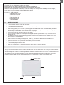
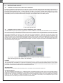
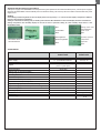
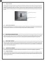
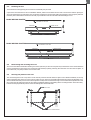
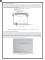
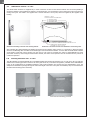
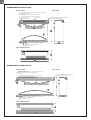
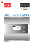
WALL-MOUNTED SWIMMING POOL DEHUMIDIFIER
USER´S MANUAL
MODEL: DRY 300 & 500 PLASTIK
2
Thank you for your decision to purchase our device.
Please read this user manual carefully before switching on the device.
Please keep the instructions in this practical guide for your quick know-how.
We do not take responsibility or warranty in case of damage, loss or impairment caused by incorrect usage,
or by usage for other purposes not described in this manual.
Contents: 1. Safety measures
2. Specifications for use
3. Instructions for use
4. Instructions for maintenance
5. Servicing the unit
6. Installation guide
7. Technical data
1.
SAFETY MEASURES
l
l
l
l
l
l
l
l
l
l
l
l
l
l
2.
Do not manipulate with the device with wet hands.
Do not spray any flammable substances into the equipment; this might lead to fire.
Do not clean the device with water.
Do not clean the equipment with aggressive cleaning agents, this might lead to damage or deformations.
When cleaning plastic parts do not use any cleaning agents unsuitable for the cover of the dehumidifier (household
cleaning agents, solvents, bleaching agents, benzene, diluents, rough cleaning powder, cresol, chemical agents).
Instead, sweep the dehumidifier cover with a soft cloth or a sponge.
Never throw or insert any objects into any hose or opening.
The cover is made of plastic. Do not manipulate with lighted cigarette, cigarette ashes, or any other kind of fire in
vicinity to this part.
Use this device exclusively for the intended purpose, as described in the attached instruction manual. Do not use
parts which are not recommended.
Never block the air opening of the product. Protect the air openings from clogging by particles, hair etc.
When the device is not running correctly (smoke, smell etc.), shut down the device by a circuit breaker in the
switchboard.
Repair and dislocation must be performed exclusively by a service technician.
Before cleaning the device, switch off the circuit breaker in the switchboard.
Do not place any objects onto the device.
When you do not intend to use the device for a longer time, switch off the circuit breaker.
SPECIFICATIONS FOR USE
The units are designed especially for use in indoor swimming pools, spas and saunas. They can also be very useful in laundries,
drying rooms and elsewhere.
2
The Microwell DRY 300 PLASTIK is designed for halls with a swimming pool surface area of up to 30 m . The Microwell DRY 500
2
PLASTIK is designed for halls with a swimming pool surface area of up to 60 m .
The condition for using the unit is maintaining the room temperature within the range between a minimum of 22°C and
a maximum of 35°C. Ideally, the air in the room should be 2-3 °C warmer than the water in the swimming pool.
EXHAUST GRID
UNIT COVER
HYGROSTAT
INTAKE GRID
WALL-MOUNTED SWIMMING POOL DEHUMIDIFIER - USER´S MANUAL
3
3.
INSTRUCTIONS FOR USE
3.1.
Humidity control by means of the built-in humidistat
The built-in humidistat is located at the bottom of the unit, on the left. The built-in hygrostat reads the humidity of the incoming air
and, depending on the set value, does or does not switch the compressor on. In the central position of the regulator, the unit secures
the average relative humidity of 60%. In indoor swimming pool halls, the correct air humidity should range from 55 to 65%.
Decreasing the humidity under this range is not desirable either from the physiological viewpoint or from the viewpoint of protection
of the building. Moreover, it increases the electricity consumption. The humidistat can be controlled by the user.
A view at the hygrostat scale
3.2.
Humidity control by means of a remote humidistat (upon request)
The dehumidifier may be, upon request, equipped with a remote humidistat. In such case, the dehumidifier has two humidistats.
One of them is built in the dehumidifier; the other one is remote, in a separate casing. The dehumidifier is primarily controlled by
the remote humidistat, provided that the built-in humidistat in the dehumidifier is set for a higher value than the remote humidistat.
If the built-in humidistat were set for a lower value than the remote humidistat, it would take over and the control of the
dehumidifier would not react to the signals from the remote humidistat. Therefore, it is best to set the built-in humidistat to the
value of 70 % RH or more. The built-in humidistat fulfils a back-up function, should the remote humidistat fail to function or should
its battery go flat. It is best to set the remote humidistat to the value in the extent of 55 to 65 % RH. Decreasing the humidity under
this range is not desirable either from the physiological viewpoint or from the viewpoint of protection of the building. Moreover, it
increases the electricity consumption.
Left: Remote control receiver, which is built into the dehumidifier by means of distribution connectors
Right: External hygrostat with a built-in radio transmitter
Location:
The remote humidistat is to be located in the most humid area of the room - usually in a corner directly opposite the dehumidifier.
This guarantees that the humidity of any area of the swimming pool hall will not exceed the humidity value set in the remote
humidistat. The regulator must not be placed on a metal plate because the plate would disturb the high frequency signal and thus
prevent the communication with the remote-controlled switch in the unit.
Automatic mode:
If the air in the room exceeds the desired humidity value, the regulator will switch the dehumidifier on.
Changing the battery:
The remote humidistat is charged by a 2 1.5V alkaline battery. Only alkaline batteries may be used, since non-alkaline batteries
might leak and damage the whole appliance. The durability of a battery is approximately 12 months. The regulator automatically
checks the level of its battery. If the battery voltage drops under the permitted value, battery sign on the display of the humidistat
comes on. It is then necessary to change the battery as soon as possible. If the battery is not changed and goes flat the
dehumidifier will be controlled by the built-in humidistat in the dehumidifier.
WALL-MOUNTED SWIMMING POOL DEHUMIDIFIER - USER´S MANUAL
4
Automatic function during a power failure:
If the power supply of the dehumidifier is interrupted during the operation of the remote humidistat, then, once the power supply is
renewed, the dehumidifier will automatically return to the latest setting. This recovery will occur within 15 minutes after the power
supply return.
Setting:
In the setting mode the brightness of the LCD display can be set. By pressing + or buttons the LCD display' s brightness is added or
reduced. This setting is for all displays.
Setting of code and test switching, relay for heating control and for dehumidification control. Data display about the manufacturer.
Average temperature and humidity display for the last 32 hours. Hysteresis setting for 19% humidity range and 0.1-0.9°C
temperature range.
Information about
the manufacturer
Statistics
Next
Heating switch on/off
Confirmation
Dehumididication
switch on/off
Back
Back
Add brightness
Humidity hysteresis
Reduce brightness
Temperature
hysteresis
Back
Back
Technical data:
Power supply
Battery longevity
Impact
Carrier frequence
Setting range of requested humidity
Setting range of requested temperature
Operating difference
Measurement precision
Control unit
Switch unit
2 x 1,5 AA alkaline batteries
230 V/0,1 VA
min. 1 year (according to battery type)
from 20 up to 30 m in building
(100 m in public place)
433,92 Mhz
15 - 85% r.h.
5 - 39 °C
5% r.h.
1,5% r.h.
Measurement sensivity of humidity
1% r.h.
Measurement sensivity of temperature
0,1% °C
Adjustable range hysteresis of humidity switching
Adjustable range hysteresis of temperature switching
Enclose temperature
Switching capacity
1 - 9% r.h.
0,1 - 0,9 °C
+20 - +40 °C
250V/8V
voltage, switching
Contact
Dimensions
Protection type
71 x 71 x 26 mm
81 x 81 x 36 mm
IP 54
WALL-MOUNTED SWIMMING POOL DEHUMIDIFIER - USER´S MANUAL
5
3.3.
Control of the fan
Under the inside cover of the unit, there is a two-position fan mode switch. In the first position, the fan runs even if the compressor
of the appliance has stopped: continuous operation of the fan. In the second position, the fan only runs simultaneously with the
compressor: periodical duty of the fan. The continuous operation mode of the fan is preferable, since the humidity reader built in
the device continuously reads humidity, and therefore a greater accuracy is reached. At the same time, continuous operation of the
fan results in better air circulation in the room. The installation work supplier selects the mode of the fan according to the request of
the user.
Continuous duty of the fan
Periodical duty of the fan
Switch of the fan operation
3.4.
Control of the compressor
Start-up of the compressor is, due to its protection, delayed by 3 minutes. Depending on the humidity of the environment, it may
take even longer for compressor to start operating. Once the compressor stops operating, the operation is renewed automatically,
at the earliest after three minutes. The user must not handle the setting element of the delay-action relay.
4.
MAINTENANCE INSTRUCTIONS
It is necessary to make sure that the suction inlet and the exhaust outlet are not covered. It is forbidden to place towels or clothing
items onto the exhaust outlets to dry them. The unit's cover can be cleaned with standard cleaning agents using a soft cloth or
a sponge. If water dripping out of the unit, please check the condensed water drain and make sure the pipe is not obstructed.
5.
SERVICING THE UNIT
At least once a year, it is necessary to have the unit checked and cleaned by a service specialist. This is inevitable to secure a long
service life of the unit. We do not recommend the user to clean the interior elements of the unit, as this might cause a damage to the
unit. The unit contains mobile elements and live elements, therefore the interior parts may only be cleaned by a certified electrician
trained to service refrigerating appliances.
6.
INSTALLATION GUIDE
The unit must be installed in compliance with the local installation and electrical installation regulations !
6.1.
Location of the unit
To ensure maximum efficiency, it is necessary to install the unit as high above the ground as possible. It is forbidden to install the
unit onto the ground. It is essential to ensure good air circulation by allowing at least 150 mm of free space under the unit and at
least 200 mm of free space above the unit. For the purposes of maintenance, it is further necessary to allow at least 200 mm of free
space on both sides of the unit.
WALL-MOUNTED SWIMMING POOL DEHUMIDIFIER - USER´S MANUAL
6
6.2.
Mounting the unit
The units have a self-supporting structure and are remarkably easy to install.
A part of the unit accessories is also an installation bracket, which must be fixed onto the wall. The axis of the fixation openings is
210 mm lower than the top edge of the unit. The fixation openings are 420 mm apart (DRY 300 PLASTIK) or 360 mm apart (DRY 500
PLASTIK). Once the bracket is mounted to the wall, it is possible to mount the unit without disassembling its cover.
Model DRY 300 PLASTIK
TOP EDGE OF THE UNIT
SPIRIT LEVEL
BRACKET
MOUNTING HOLES
Model DRY 500 PLASTIK
TOP EDGE OF THE UNIT
SPIRIT LEVEL
BRACKET
MOUNTING HOLES
6.3.
Dismounting and mounting the cover
The cover can be dismounted after releasing two screws (DRY 300) or three screws (DRY 500) at the bottom of the unit. Release the
screws, pull the bottom part of the cover toward yourself and then, by lifting it shortly, rake down the cover from the rear plate. To
mount the cover, carry the procedure out in reverse order.
6.4.
Securing the position of the unit
The unit is designed in such a way that it can be securely mounted and will hold in its place even if lifted accidentally. In the top
edges of the back plate, there are screw holes for safety screws, which are accessible after dismounting the front fibreglass cover.
Arrows indicate the safety screw holes in the back plate. A safety screw is fastened through a screw hole in the back plate into a wall
plug in the wall. This will prevent the unit from being accidentally pulled out and falling off the mounting bracket. At the same time,
it will secure the perpendicular position of the unit and align the unit with the wall.
BACK PLATE
SAFETY SCREW HOLES
WALL-MOUNTED SWIMMING POOL DEHUMIDIFIER - USER´S MANUAL
7
6.5.
Drainage of condensate
Condensed water is drained from the unit by the force of gravity. It is necessary to situate the unit in such a way that there is
sufficient declivity for the drainage of condensed water. The condensation product must be drained through a siphon into a sewer or
into the outside environment. It is strictly forbidden to drain the condensed water back into the swimming pool, as it may be
polluted by bacteria. A pipe for condensate drainage is led out at the bottom of the unit, on the left. This pipe is to be inserted into a
sewerage pipe with the inside diameter of at least 18 mm.
50
50
117
117
ATTACHMENT OF THE HEATER ELEMENT TO THE DISTRIBUTION
OF THE HEATING WATER
THREAD G ½ '’ MALE
OPTIONS LOCATION OF CONNECTION
A1 - FROM LEFT SIDE
A2 - FROM RIGHT SIDE
A3 - FROM BACK SIDE
40 35
15
35
50
100
CONDENSATE DRAINAGE (FROM THE REAR)
PIPING WITH MINIMUM INTERNAL DIAMETER OF 18 mm
POWER SUPPLY (FROM THE REAR)
2
CYSY WIRE 3C x 1.5 (3C x 2.5) mm
CONNECTIONS ARE VALID FOR MODELS DRY 300 PLASTIK AS WELL DRY 500 PLASTIK - FRONT VIEW
6.6
Connection of the unit onto the mains
Connection of the unit onto the mains must conform to relevant safety standards. Connection requirements: Power supply: 220240V / 50Hz. Protection: 10A (DRY 300 PLASTIK) or 16A (DRY 500 PLASTIK) by a protective switch with nominal differential dropout current not exceeding 30 mA. The unit's terminal board for connection onto the electric mains is situated on the left hand-side of
the unit. The main switch of the unit must be situated outside of the swimming pool hall. The main switch of the unit must be
bipolar, with switch-out breaking of conductors L and N. An appliance for disconnecting the unit from the mains must be embedded
into a firm surface. The distance of contacts, when swithched off, must be at least 3 mm for all poles. The connection of the
appliance to the electric mains must be carried out by a certified electrician.
An example of preparation of electric power supply, condensate drainage
and mounting of the bracket
WALL-MOUNTED SWIMMING POOL DEHUMIDIFIER - USER´S MANUAL
8
LOCATION OF THE EQUIPMENT
The location must be in compliance with the HD 384.7.702 S1, IEC 60364-7-702 standard.
It is recommended to situate the unit outside zones 0, 1 and 2.
In case the unit is situated into zones 2 or 1, it must be adhered to the HD, IEC standard.
ZONE 1, IPX4
Swimming pools which are not
cleaned by jet water
in the distance of 1250 to 2000 mm from the swimming pool edge,
the unit must adhere to the HD, IEC standard and in the height
of at least 300 mm from the floor
ZONE 2, IPX2
OUTSIDE THE ZONES
Swimming pools which
are not cleaned by jet water
In the distance of 2000 to 3500 mm
from the swimming pool edge, the
unit must adhere to the HD, IEC
standard and a minimum 150 mm
elevation above the ground is
required for sufficient air flow.
Installing the unit on the floor is
prohibited.
SWIMMING POOL
At least 1250 mm (i.e. out of the reach of the hand)
from the lateral edge of the shower cabinet. It cannot
be placed above the shower cabinet.
In the distance of 1250 mm or less
from the swimming pool edge, the
bottom edge of the unit must be in
the height of 2500 mm from the
swimming pool surface; if it is
embedded under the floor, then
2500 mm from the floor.
At least 1250 mm (i.e. out of the reach of the hand) from the lateral edge
of the wash basin, in the minimum height of 1200 mm above ground. It
cannot be placed above the wash basin.
OUTSIDE THE ZONES
OUTSIDE THE ZONES
In the distance of at least 1500 mm
from the vertical plane around the
jumping platforms, diving boards
and 2500 mm above the highest
surface, where persons are likely to
stay.
SWIMMING POOL
If the unit is in the distance of less
or equal to 1250 mm horizontally
from the edge of the swimming
pool, then it must be raised up to
the height of 2500 mm from the
swimming pool surface; if the
pool is embedded under the floor,
then the unit must be raised up to
the height of 2500 mm from the
floor.
It is inevirable to locate the unit outside the zones, where cleaning by jet water is supposed. Connection of the unit to the mains and
its protection must correspond with the applicable standards. Electrical supply of the unit must be carried out by a protective
isolating transformer or it must be protected by a current protective switch with a nominal differential cut-off current not exceeding
30 mA.
WALL-MOUNTED SWIMMING POOL DEHUMIDIFIER - USER´S MANUAL
9
6.7.
LPHW heater element - to order
The LPHW heater elements are supplied only to order. Connection of the hot water heater element onto the LPHW plumbing is
carried out similarly to the installation of radiators. On the feeder pipe, it is connected by a control valve and on the return pipe by a
closing screw joint. The LPHW is not supplied with a control valve and a screw joint; these are supplied by the supplier of the
heating.
THREAD G ½ '’ MALE
OPTIONS LOCATION OF CONNECTION
50
50
117
117
A1 - FROM LEFT SIDE
A2 - FROM RIGHT SIDE
A3 - FROM BACK SIDE
40 35
15
35
50
100
CONDENSATE DRAINAGE (FROM THE REAR)
PIPING WITH MINIMUM INTERNAL DIAMETER OF 18 mm
POWER SUPPLY (FROM THE REAR)
2
CYSY WIRE 3C x 1.5 (3C x 2.5) mm
Attachment threading of the hot water heating element
Attachment of the heater element to the distribution of the heating water
After installing the LPHW plumbing and leading the LPHW into the element under pressure, it is necessary to bleed the heater
element. The bleeding valve is located on the feeder pipe of the LPHW heater element. To secure that the LPHW heater element
works always at full heat output, blowing onto the unit by a fan must be provided even when no dehumidification is being
performed. Therefore, when using the LPHW heater element, the switch of fan operation must be switched into the position of
continuous operation.
6.8.
Mounting behind the wall - to order
The dehumidifiers are simply adapted also to installation behind the wall into the adjacent room. In such case, only two grids are
visible in the swimming pool area. These are the same grids which are, in the basic configuration, installed on the dehumidifier's
cover. In the configuration for installation behind the wall, conduit adapters are screwed onto the dehumidifier's cover. The
adapters are delivered for passage through the wall of the length of 400 mm. In the place of installation, they are shortened from
the side of the swimming pool as necessary.
View from the adjacent room
WALL-MOUNTED SWIMMING POOL DEHUMIDIFIER - USER´S MANUAL
View from the swimming pool hall
10
SHORTEN THE PIPING AS NECESSARY
MOUNTING FROM INSIDE: REINFORCE THE PIPING TO THE VALUE OF 65 MM
AND FROM THE OUTER SIDE - PUR FOAM HAS TO BE GLUED TO THE MASONRY.
AFTER HARDENING OF THE PUR FOAM, REMOVE THE FORTIFICATION AND
MOUNT THE GRID.
DRY 300 PLASTIK
DRY 500 PLASTIK
PIPING 615x65mm - DRY 300 PLASTIK
(PIPING 1075x65mm - DRY 500 PLASTIK)
FLANGED CONNECTION
ELBOW 135° 615x65mm - DRY 300 PLASTIK
(ELBOW 135° 1075x65mm - DRY 500 PLASTIK)
R100
25 mm WIDE FLANGE
DEHUMIDIFIER
25 mm WIDE FLANGE
300 PLASTIK
500 PLASTIK
R100
ELBOW 135° 615x65mm - DRY 300PLASTIK
(ELBOW 135° 1075x65mm - DRY 500 PLASTIK)
FLANGED CONNECTION
MOUNTING FROM INSIDE: REINFORCE THE PIPING TO THE VALUE OF 65 MM
AND FROM THE OUTER SIDE - PUR FOAM HAS TO BE GLUED TO THE MASONRY.
AFTER HARDENING OF THE PUR FOAM, REMOVE THE FORTIFICATION AND
MOUNT THE GRID.
PIPING 615x65mm - DRY 300 PLASTIK
(PIPING 1075x65mm - DRY 500 PLASTIK)
SHORTEN THE PIPING AS NECESSARY
7.
TECHNICAL DATA
TYPE
UNITS
DRY 300 PLASTIK
2
m
For swimming pools with a maximum surface area
30
DRY 500 PLASTIK
60
DEHUMIDIFICATION PERFORMANCE:
66
at 30°C and 60% RH
at 30°C and 70% RH
l/24 h
l/24 h
33
42
82
at 30°C and 80% RH
l/24 h
47
101
Operating temperature range
°C
22-35
22-35
Operating humidity range
%
3
m /h
20-100
20-100
440
740
Heat output
Power consumption
dB (A)
W
W
42
1900
700
44
3500
1000
Voltage
V/Hz/f
230/50/1
230/50/1
Operating current / Starting current
A
4.4 / 15.8
7.5 / 30
Protection
A
10
16
Air flow
Noisiness (in 1 m distance)
Coverage
IP
44
2
44
Conductor
Condensate drain - minimum inside diameter
mm
mm
CYSY 3C x 1.5
d 18
Dimensions (width x height x depth)
mm
780 x 653 x 255
1245 x 653 x 255
Dimensions of package (width x height x depth)
Weight - net / in package
mm
kg
850 x 735 x 345
40/46
1315 x 735 x 345
60/69
Refrigerant - R 410 A
kg
Max. pressures in the system HP/LP
bar
28.5/8.5
28.5/8.5
Dehumidifier efficiency rate
DER
2.4
2.7
Remote control - wireless - with an adjustable dial
OPTIONAL EXTRAS
yes/no
LPHW heater element - heat output at water temp. 90/70°C
Connecting thread of the LPHW heater element
0.5
W
thread
CYSY 3C x 2.5
d 18
0.75
yes
yes
2000
male G 1/2”
4000
male G 1/2”
WALL-MOUNTED SWIMMING POOL DEHUMIDIFIER - USER´S MANUAL
11
DIMENSIONS DRY 300 PLASTIK
SIDE VIEW
FRONT VIEW
ATTACHMENT OF THE LPHW HEATER ELEMENT TO THE DISTRIBUTION
OF THE HEATING WATER
- (MODELS WITH THE LPHW HEATER ELEMENT ONLY)
THREAD G ½ '’
THE POSITION AGAINST GETTING LOOSE FROM
THE BRACKET
BRACKET
(FROM THE REAR)
THE POSITION AGAINST GETTING LOOSE FROM
THE BRACKET (FROM THE REAR)
CONDENSATE DRAINAGE (FROM THE REAR)
PIPING WITH MINIMUM INTERNAL DIAMETER OF 18 mm
POWER SUPPLY (FROM THE REAR)
2
CYSY WIRE 3C x 1.5 mm
VIEW FROM BELOW
DIMENSIONS DRY 500 PLASTIK
SIDE VIEW
FRONT VIEW
ATTACHMENT OF THE LPHW HEATER ELEMENT TO THE DISTRIBUTION
OF THE HEATING WATER
- (MODELS WITH THE LPHW HEATER ELEMENT ONLY)
THREAD G ½ '’
THE POSITION AGAINST GETTING LOOSE
FROM THE BRACKET (FROM THE REAR)
BRACKET
CONDENSATE DRAINAGE (FROM THE REAR)
PIPING WITH MINIMUM INTERNAL DIAMETER OF 18 mm
POWER SUPPLY (FROM THE REAR)
CYSY WIRE 3C x 1.5 mm2
VIEW FROM BELOW
WALL-MOUNTED SWIMMING POOL DEHUMIDIFIER - USER´S MANUAL
THE POSITION AGAINST GETTING LOOSE FROM
THE BRACKET (FROM THE REAR)
12
WIRING DIAGRAM OF MODEL MICROWELL DRY 300 PLASTIK
inbuilt wireless humidistat DRY EASY 200
without inbuilt wireless humidistat DRY EASY 200
MECHANICAL
HUMIDISTAT
orange 3 FAN MODE SWITCH
FAN
2 blue
1
brown
3
2
MECHANICAL
HUMIDISTAT orange 3
M
1
C
brown
2 3
brown
M
C
brown
WIRELESS HUMIDISTAT
black
brown
white
LOW
PRESSURE
PRESSOSTAT
(L)
1
1
black
FAN MODE SWITCH
FAN
2 blue
brown
DRY EASY 200
white
LOW PRESSURE
PRESSOSTAT(L)
8 7 6 5 4 3 2 1
TIME RELAY
white
A1
A2
TIME RELAY
A2
A1
white
blue
t
18
15
blue
18
15
grey
grey
brown
A2
7
K1
A1
L
N
PE
SWITCHING
RELAY
brown
brown
A2
protection
red
blue
protection
red
M
blue
M
violet
COMPRESSOR
violet
COMPRESSOR
L
N
PE
4
A1
4
brown
blue
SWITCHING
RELAY
7
K1
blue
blue
blue
blue
WIRING DIAGRAM OF MODEL MICROWELL DRY 500 PLASTIK
inbuilt wireless humidistat DRY EASY 200
M
white SWITCHING RELAY
A2
9
R2
LOW
PRESSURE
PRESSOSTAT
(L)
6
blue
FAN
slow speed
1
black
orange
3
2
FAN MODE SWITCH
grey
white
grey
black
orange
LOW
PRESSURE
PRESSOSTAT
(L)
MECHANICAL
HUMIDISTAT
blue
black
orange
MECHANICAL
FAN MODE SWITCH
HUMIDISTAT
grey
2 3
slow speed
grey
1
black
orange
SWITCHING RELAY
A2
8 7 6 5 4 3 2 1
6
black
blue
orange
black
blue
brown
orange
white
TIME RELAY
A1
A2
t
18
15
grey
A2
white
DRY EASY 200
9
R2
black
black
blue
WIRELESS HUMIDISTAT
M
blue
without inbuilt wireless humidistat DRY EASY 200
TIME RELAY
A1
A2
brown
t
15
18
TERMINAL BOARD
TERMINAL BOARD
brown
blue
green-yellow
brown
A2
brown
blue
green-yellow
brown
grey
L
N
PE
L
N
PE
7
R1
7
R1
4
4
COMPRESSOR
red
COMPRESSOR
red
blue
M
violet
C
violet
blue
blue
M
blue
COMPRESSOR
CONDENSOR
blue
blue
COMPRESSOR
CONDENSOR
Note: Producer reserves right to make changes on wiring.
WALL-MOUNTED SWIMMING POOL DEHUMIDIFIER - USER´S MANUAL
13
OUTPUT DIAGRAM OF DEHUMIDIFICATION (DRY 300 PLASTIK)
(l/24h)
60
80%
70%
60%
40
50%
30
40%
Relative humidity
Dehumidification output
50
20
10
0
15
20
25
30
35
(°C)
Air temperature
OUTPUT DIAGRAM OF DEHUMIDIFICATION (DRY 500 PLASTIK)
80%
100
70%
80
60%
50%
60
40%
40
20
0
15
20
25
Air temperature
WALL-MOUNTED SWIMMING POOL DEHUMIDIFIER - USER´S MANUAL
30
35
(°C)
Relative humidity
Dehumidification output
(l/24h)
120
14
8.
WARRANTY CONDITIONS
The following exceptions stated by Microwell, Ltd. apply within the warranty.
No claims will be accepted if:
1.
2.
3.
4.
5.
6.
The
The
The
The
The
The
dehumidifier is used in an incorrect way, not as described in this manual.
dehumidifier is installed in an incorrect way, not as described in this manual.
dehumidifier was put to operation by an unauthorized person.
air flow through the dehumidifier is out of the defined borders.
water flow through the dehumidifier is out of the defined borders.
water´s pH level and/or chemical condition is out of the defined borders:
Acidity / pH level:
pH
7,4 +/- 0,4
Total alkalinity, as CaCO3
ppm
80-120
Total hardness, as CaCo3
ppm
100-300
Total melted dry mass
ppm
max. 3000
Maximal saline content
wt/wt
6%
Free chlorine range
ppm
1,0-3,0
Superchlorination
ppm
Bromine
ppm
2-3
Baquacil
ppm
25-50
Ozone
ppm
0,8-1,0
Maximum copper content
ppm
max. 2
Aquamatic single purifier
ppm
max. 2
Tarn clean purifier
ppm
max. 2
Sherwood purifier
ppm
max. 2
max. 30 ppm/max. 24 hours
7. The dehumidifier suffered frost damage.
8. The electric tension source is insufficient or improper in any other way.
IN CASE OF ANY UNCERTAINTY YOU MAY HAVE, PLEASE FEEL FREE TO CONTACT US !
NOTE:
When applying applicable warranty, the registration card that ensures applicable warranties must be returned. In case
you cannot find the registration card of your dehumidifier, please contact the Service department of Microwell, Ltd. indicated your name, address and serial number of your dehumidifier. The registration card will be then sent to you for
filling in. In case you have any service or technique related questions, please specify the model number and serial
number of your dehumidifier. These information will help us in making proper diagnosing of your unit and the service can
be performed with a minimum time delay.
TRANSPORT INSTRUCTIONS:
The dehumidifiers must be transported only in the original packaging and in a vertical position. Make sure that the
dehumidifier cannot turn over or fall down during transportation. Do never put the dehumidifier aside! It may lead to
serious compressor damage! No claims are accepted in case of any damage caused by transportation. When receiving
the product delivered to you, please check whether the package is not damaged. If any kind of objections occurs, please
make a proper documentation of them.
WALL-MOUNTED SWIMMING POOL DEHUMIDIFIER - USER´S MANUAL
MICROWELL, Ltd.
Distributed by:
SNP 2018/42
927 01 Šaľa, Slovakia
Phone: +421 31 7020 540-1
Fax: +421 31 7020 542
E-mail: [email protected]
www.microwell.eu
VERSION: 2012/08/15