1
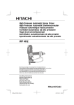
GB Auto Feed Screwdriver
Instruction Manual
F
Visseuse à recharge automatique
Manuel d’instructions
D
Magazin-Schnellbauschrauber
Betriebsanleitung
I
Avvitatore ad auto-alimentazione
Istruzioni per l’uso
NL Schroef automaat
Gebruiksaanwijzing
E
Atornillador autoalimentado
Manual de instrucciones
P
Chave de parafusos com alimentação
automática
Manual de instruções
DK Magasin Skrueautomat
Brugsanvisning
S
Skruvdragare med automatisk matning Bruksanvisning
N
Skrutrekker med automatisk tilførsel
Bruksanvisning
SF Makasiini-pikaruuvinväännin
Käyttöohje
GR Γεµιστήρας ταχυβιδωτήρας
Οδηγίες χρήσεως
6833
6834
6836
2
1
2
5
4
6
3
B
4
A
1
2
7
10
8
9
3
4
11
5
6
13
14
12
7
2
15
8
4
16
9
10
19
18
20
2
17
15 mm
11
12
21
22
13
14
23
24
15
3
Symbols
The followings show the symbols used for the tool. Be sure that you understand their meaning before use.
Symboles
Nous donnons ci-dessous les symboles utilisés pour l’outil. Assurez-vous que vous en avez bien compris la signification avant d’utiliser l’outil.
Symbole
Die folgenden Symbole werden für die Maschine verwendet. Machen Sie sich vor der Benutzung unbedingt mit ihrer
Bedeutung vertraut.
Simboli
Per questo utensile vengono usati i simboli seguenti. Bisogna capire il loro significato prima di usare l’utensile.
Symbolen
Voor dit gereedschap worden de volgende symbolen gebruikt. Zorg ervoor dat u de betekenis van deze symbolen
begrijpt alvorens het gereedschap te gebruiken.
Símbolos
A continuación se muestran los símbolos utilizados con esta herramienta. Asegúrese de que entiende su significado
antes de usarla.
Símbolos
O seguinte mostra os símbolos utilizados para a ferramenta. Certifique-se de que compreende o seu significado antes
da utilização.
Symboler
Nedenstående symboler er anvendt i forbindelse med denne maskine. Vær sikker på, at De har forstået symbolernes
betydning, før maskinen anvendes.
Symboler
Det följande visar de symboler som används för den här maskinen. Se noga till att du förstår deras innebörd innan
maskinen används.
Symbolene
Følgende viser de symblene som brukes for maskinen. Det er viktig å forstå betydningen av disse før maskinen tas i
bruk.
Symbolit
Alla on esitetty koneessa käytetyt symbolit. Opettele näiden merkitys, ennen kuin käytät konetta.
Σύµβολα
Τα ακλουθα δείχνουν τα σύµβολα που χρησιµοποιούνται για το µηχάνηµα. Βεβαιωθείτε τι
καταλαβαίνετε τη σηµασία τους πριν απ τη χρήση.
4
❏ Read instruction manual.
❏ Lire le mode d’emploi.
❏ Bitte Betriebsanleitung lesen.
❏ Leggete il manuale di istruzioni.
❏ Lees de gebruiksaanwijzing.
❏ Lea el manual de instrucciones.
❏ Leia o manual de instruções.
❏ Læs brugsanvisningen.
❏ Läs bruksanvisningen.
❏ Les bruksanvisingen.
❏ Katso käyttöohjeita.
❏ ∆ιαβάστε τις οδηγίες χρήσης.
❏ DOUBLE INSULATION
❏ DOUBLE ISOLATION
❏ DOPPELT SCHUTZISOLIERT
❏ DOPPIO ISOLAMENTO
❏ DUBBELE ISOLATIE
❏ DOBLE AISLAMIENTO
❏ DUPLO ISOLAMENTO
❏ DOBBELT ISOLATION
❏ DUBBEL ISOLERING
❏ DOBBEL ISOLERING
❏ KAKSINKERTAINEN ERISTYS
❏ ∆ΙΠΛΗ ΜΟΝΩΣΗ
ENGLISH
Explanation of general view
1
2
3
4
5
6
7
8
Lever
Stopper base
Plate
Casing
Approx. 5 mm
Adjusting knob
Feeder box
Screw strip
9
10
11
12
13
14
15
16
Screw guide
Driving position
Reverse button
Hook
Lock button
Switch trigger
Reversing switch
Thumb screws
17
18
19
20
21
22
23
24
Bit
Dust cover
Plain bearing
Wall
Extension handle
Limit mark
Screwdriver
Brush holder cap
SPECIFICATIONS
Model
6833
Screw strip ....................................... 4 mm x 25 mm – 41 mm
-1
No load speed (min ) ...................... 4,700
Overall length .................................. 364 mm
Net weight ........................................ 1.9 kg
• Due to our continuing program of research and development, the specifications herein are subject to change
without notice.
• Note: Specifications may differ from country to country.
Intended use
The tool is intended for screw driving in wood, metal and
plastic.
Power supply
The tool should be connected only to a power supply of
the same voltage as indicated on the nameplate, and can
only be operated on single-phase AC supply. They are
double-insulated in accordance with European Standard
and can, therefore, also be used from sockets without
earth wire.
6834
4 mm x 25 mm – 57 mm
2,800
396 mm
1.9 kg
6836
4 mm x 25 mm – 41 mm
6,000
364 mm
1.9 kg
OPERATING INSTRUCTIONS
Setting for desired screw length (Fig. 1)
There are 3 (for Model 6833 & 6836) or 5 (for
Model 6834) positive-lock screw length settings. To
obtain the desired setting, pull out the stopper base while
depressing the lever until you see the number of the
desired screw length (indicated on the plate) appear to
rest on the very top edge of the casing. See the table
below for the relation between the number indicated on
the plate and the respective screw length ranges.
Number indicated
on the plate
Screw length range
(mm)
25/28
25 – 28
Safety hints
For your own safety, please refer to the enclosed safety
instructions.
32
28 – 35
40
35 – 41
ADDITIONAL SAFETY RULES
*51
41 – 51
*57
51 – 57
1.
2.
3.
4.
5.
6.
Hold tool by insulated gripping surfaces when
performing an operation where the cutting tools
may contact hidden wiring or its own cord. Contact with a “live” wire will make exposed metal
parts of the tool “live” and shock the operator.
Always be sure you have a firm footing. Be sure
no one is below when using the tool in high locations.
Hold the tool firmly.
Keep hands away from rotating parts.
Do not leave the tool running. Operate the tool
only when hand-held.
Do not touch the drill bit or the workpiece immediately after operation; they may be extremely
hot and could burn your skin.
SAVE THESE INSTRUCTIONS.
(Note) * for Model 6834 only
Adjusting the driving depth (Fig. 2)
Depress the stopper base as far as it will go. While keeping it in this position, turn the adjusting knob until the bit
tip projects approx. 5 mm from the stopper base. Drive a
trial screw. If the screw head projects above the surface
of the workpiece, turn the adjusting knob in the A direction; if the screw head is countersunk, turn the adjusting
knob in the B direction.
Installing screw strip (Fig. 3 & 4)
Insert the screw strip through the screw guide. Then
insert it through the feeder box until the first screw
reaches the position next to the driving position.
Removing screw strip (Fig. 5 & 6)
To remove the screw strip, just pull it out in the direction
of the arrow. If you depress the reverse button, you can
pull out the screw strip in the reverse direction of the
arrow.
5
Carry hook (Fig. 7)
Extension handle (optional accessory) (Fig. 13)
The carry hook is convenient for hooking the tool to your
belt. It can be installed on either side of the tool. To
remove it, pull it out in the direction of the arrow while
raising. To install the hook, push it down until it “clicks”
into place on the tool.
Use of extension handle allows you to drive screws into
floors while standing.
Switch action (Fig. 8)
CAUTION:
Before plugging in the tool, always check to see that the
switch trigger actuates properly and returns to the “OFF”
position when released.
To start the tool, simply pull the trigger. Release the trigger to stop. For continuous operation, pull the trigger and
then push in the lock button. To stop the tool from the
locked position, pull the trigger fully, then release it.
Reversing switch action (Fig. 8)
CAUTION:
• Always check the direction of rotation before operation.
• Use the reversing switch only after the tool comes to a
complete stop. Changing the direction of rotation
before the tool stops may damage the tool.
This tool has a reversing switch to change the direction of
rotation. Press the upper side (FWD side) of the switch
for clockwise rotation or the lower side (REV side) of the
switch for counterclockwise rotation.
Driving operation (Fig. 9)
Switch on the tool by pressing the trigger and at the
same time pushing the lock button. Hold the tool squarely
against the workpiece and apply forward pressure to the
tool. The screw will be automatically carried to the driving
position and driven into the workpiece.
Important:
• Do not fire the tool without screws. This will damage
the workpiece.
• If the feeder box becomes sluggish in operation, spray
car wax (spray type wax) on its sliding surfaces. Never
lubricate it.
Installing or removing bit (Fig. 10 & 11)
Important:
Always be sure that the tool is switched off and
unplugged before installing or removing the bit.
Loosen the thumb screws which secure the casing. Pull
out the casing in the direction of the arrow. Press the dust
cover toward the plain bearing and pull out the bit. If the
dust cover cannot be moved as far as the plain bearing,
try it again after turning the bit slightly. To install the bit,
insert it into the socket while turning it slightly. After
installing, always make sure that the bit is securely held
in place by trying to pull it out.
Driving in corner (Fig. 12)
This tool can be used to drive at a position 15 mm away
from the wall as shown in Fig. 12.
CAUTION:
Driving at a position closer than 15 mm to the wall or driving with the stopper base in contact with the wall may
damage the screw heads and cause wear on the bit. This
may also lead to poor fastening of screws and malfunction of the tool.
6
MAINTENANCE
CAUTION:
Always be sure that the tool is switched off and
unplugged before carrying out any work on the tool.
Replacement of carbon brushes (Fig. 14 & 15)
Replace carbon brushes when they are worn down to the
limit mark. Both identical carbon brushes should be
replaced at the same time.
To maintain product safety and reliability, repairs, maintenance or adjustment should be carried out by a Makita
Authorized Service Center.
NEDERLANDS
Verklaring van algemene gegevens
1
2
3
4
5
6
7
8
Hendel
Stopvoet
Plaat
Behuizing
Ongeveer 5 mm
Regelknop
Toevoerbox
Schroefstrip
9
10
11
12
13
14
15
16
Schroefgeleider
Inschroefpositie
Omkeerknop
Haak
Vergrendelknop
Trekschakelaar
Omkeerschakelaar
Vleugelschroeven
TECHNISCHE GEGEVENS
Model
6833
Schroefstrip .....................................4 mm x 25 mm – 41 mm
-1
Toerental onbelast (min ) ............... 4 700
Totale lengte .................................... 364 mm
Netto gewicht ................................... 1,9 kg
17
18
19
20
21
22
23
24
Bit
Stofkap
Lager
Muur
Verlenghandgreep
Limietmarkering
Schroevendraaier
Borstelhouderkap
6834
4 mm x 25 mm – 57 mm
2 800
396 mm
1,9 kg
6836
4 mm x 25 mm – 41 mm
6 000
364 mm
1,9 kg
• In verband met ononderbroken research en ontwikkeling behouden wij ons het recht voor bovenstaande
technische gegevens te wijzigen zonder voorafgaande
kennisgeving.
• Opmerking: De technische gegevens kunnen van land
tot land verschillen.
6.
Doeleinden van gebruik
Dit gereedschap is bedoeld voor het indraaien van
schroeven in hout, metaal en kunststof.
BEDIENINGSVOORSCHRIFTEN
Stroomvoorziening
De machine mag alleen worden aangesloten op een
stroombron van hetzelfde voltage als aangegeven op de
naamplaat, en kan alleen op enkel-fase wisselstroom
worden gebruikt. De machine is dubbel-geïsoleerd volgens de Europese standaard en kan derhalve ook op
een niet-geaard stopkontakt worden aangesloten.
Veiligheidswenken
Voor uw veiligheid dient u de bijgevoegde Veiligheidsvoorschriften nauwkeurig op te volgen.
AANVULLENDE
VEILIGHEIDSVOORSCHRIFTEN
1.
2.
3.
4.
5.
Houd het gereedschap bij de geïsoleerde handgreepoppervlakken vast wanneer de kans bestaat dat het gereedschap per ongeluk op
verborgen elektrische bedrading of op zijn eigen
netsnoer schroeft. Door contact met een onder
spanning staande draad, komen de metalen
onderdelen van het gereedschap onder spanning te staan en kan de gebruiker een elektrische schok krijgen.
Zorg er altijd voor dat u stevige steun voor de
voeten hebt. Zorg ervoor dat niemand zich onder
het gereedschap bevindt wanneer u dit op hoge
plaatsen gebruikt.
Houd het gereedschap goed vast.
Houd uw handen uit de buurt van draaiende
onderdelen.
Laat het gereedschap niet achter terwijl het nog
draait. Bedien het gereedschap alleen terwijl u
met de handen vasthoudt.
Raak de bit of het werkstuk niet aan onmiddellijk
na het gebruik; deze kunnen zeer heet zijn en
brandwonden veroorzaken.
BEWAAR DEZE VOORSCHRIFTEN.
Instellen van de gewenste schroeflengte (Fig. 1)
Er zijn 3 (voor Model 6833 en 6836) of 5 (voor
Model 6834) schroeflengte-instellingen beschikbaar. Om
de gewenste instelling te krijgen, trekt u de stopvoet naar
buiten terwijl u de hendel naar beneden drukt totdat het
getal van de gewenste schroeflengte (aangeduid op de
plaat) net boven de bovenrand van de behuizing komt te
staan. Raadpleeg de onderstaande tabel voor de verhouding tussen de getallen aangeduid op de plaat en de
overeenkomstige schroeflengten.
Getal aangeduid
op de plaat
Schroeflengtebereik
(mm)
25/28
25 – 28
32
28 – 35
40
35 – 41
*51
41 – 51
*57
51 – 57
(Opmerking) * alleen voor Model 6834
Instellen van de schroefdiepte (Fig. 2)
Druk de stopvoet zo ver mogelijk in. Houd hem in deze
positie en draai de regelknop tot de bitpunt ongeveer 5
mm uit de stopvoet steekt. Draai een testschroef in.
Indien de schroefkop boven het oppervlak van het werkstuk uitsteekt, moet u de regelknop in de “A” richting draaien; indien de schroefkop verzonken zit, moet u de
regelknop in de “B” richting draaien.
13
Aanbrengen van de schroefstrip (Fig. 3 en 4)
Steek de schroefstrip door de schroefgeleider. Steek
hem vervolgens door de toevoerbox tot de eerste schroef
naast de inschroefpositie komt te zitten.
Verwijderen van de schroefstrip (Fig. 5 en 6)
Om de schroefstrip te verwijderen, trekt u hem gewoon in
de richting van het pijltje. Als u de omkeerknop indrukt,
kunt u de schroefstrip in de omgekeerde richting van het
pijltje eruit trekken.
Draaghaak (Fig. 7)
De draaghaak is handig om het gereedschap aan uw
gordel vast te haken. Hij kan aan de linker- of rechterzijde van het gereedschap worden bevestigd. Om de haak
te verwijderen, heft u hem op en trekt u hem in de
richting van het pijltje. Om de haak te bevestigen, drukt u
hem omlaag tot hij op het gereedschap vastklikt.
Werking van de trekschakelaar (Fig. 8)
LET OP:
Alvorens de stekker van het gereedschap in het stopcontact te steken, moet u altijd controleren of de trekschakelaar goed werkt en bij loslaten naar de “OFF” stand
terugkeert.
Om het gereedschap in te schakelen, drukt u de trekschakelaar gewoon in. Laat de trekschakelaar los om te
stoppen. Voor continuë werking, de trekschakelaar
indrukken en dan de vergrendelknop indrukken. Om het
gereedschap vanuit deze vergrendelde stand te doen
stoppen, de trekschakelaar helemaal indrukken en dan
loslaten.
Installeren of verwijderen van de bit
(Fig. 10 en 11)
Belangrijk:
Zorg er altijd voor dat het gereedschap is uitgeschakeld
en zijn stekker uit het stopcontact is verwijderd alvorens
de bit te installeren of te verwijderen.
Draai de vleugelschroeven los waarmee de behuizing is
bevestigd. Verwijder de behuizing in de richting van het
pijltje. Duw de stofkap in de richting van het lager en trek
de bit eruit. Wanneer de stofkap niet tot tegen het lager
kan worden geduwd, verdraai de bit dan een beetje en
probeer opnieuw.
Om de bit te installeren, steekt u hem in de houder terwijl
u hem lichtjes draait. Controleer na het installeren altijd
of de bit goed vastzit door eraan te trekken.
Schroeven in hoeken (Fig. 12)
Dit gereedschap kan worden gebruikt voor inschroeven
op minimaal 15 mm van de muur vandaan, zoals afgebeeld in Fig. 12.
LET OP:
Indien u inschroeft op een plaats die minder dan 15 mm
van de muur is verwijderd, of inschroeft terwijl de stopvoet de muur raakt, kunnen de schroefkoppen beschadigd raken en zal de bit rapper verslijten. Bovendien
zullen de schroeven dan mogelijk niet goed vastgezet
zijn en kan het gereedschap defect raken.
Verlenghandgreep
(los verkrijgbaar accessoire) (Fig. 13)
Door de verlenghandgreep te gebruiken kunt
schroeven in vloeren indrijven terwijl u rechtop staat.
u
Werking van de omkeerschakelaar (Fig. 8)
LET OP:
• Controleer altijd de draairichting alvorens het gereedschap te gebruiken.
• Gebruik de omkeerschakelaar alleen nadat de motor
volledig tot stilstand is gekomen. Als u de draairichting
verandert alvorens de motor is gestopt, kan het
gereedschap beschadigd raken.
ONDERHOUD
Dit gereedschap heeft een omkeerschakelaar voor het
veranderen van de draairichting. Druk de bovenzijde
(FWD zijde) van de schakelaar in voor rechtse draairichting, en de onderzijde (REV zijde) voor linkse draairichting.
Vervang de borstels wanneer ze tot aan de aangegeven
limiet zijn afgesleten. Beide koolborstels dienen tegelijkertijd te worden vervangen.
Bediening voor inschroeven (Fig. 9)
Schakel het gereedschap in door de trekschakelaar en
de vergrendelknop tegelijkertijd in te drukken. Houd het
gereedschap recht tegen het werkstuk en druk het naar
voren. De schroef wordt automatisch naar de inschroefpositie gebracht en in het werkstuk gedraaid.
Belangrijk:
• Laat het gereedschap niet werken zonder schroeven
erin. Daardoor zal het werkstuk namelijk beschadigd
worden.
• Wanneer de toevoerbox niet meer soepel werkt, spuit
dan autoboenwas (spuittype was) op zijn glijvlakken.
Nooit smeren.
14
LET OP:
Zorg er altijd voor dat de machine is uitgeschakeld en de
stekker uit het stopcontact is verwijderd alvorens onderhoud aan de machine uit te voeren.
Vervangen van koolborstels (Fig. 14 en 15)
Opdat het gereedschap veilig en betrouwbaar blijft, dienen alle reparaties, onderhoud of afstellingen te worden
uitgevoerd bij een erkend Makita service centrum.