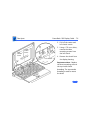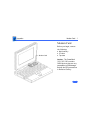
1
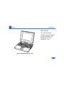
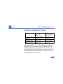
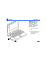
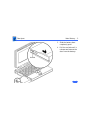
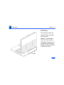
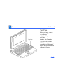
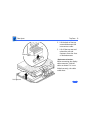
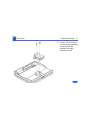
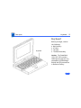
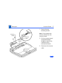
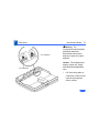
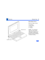
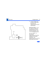
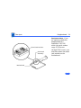
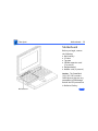
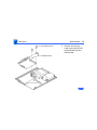
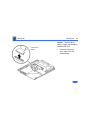
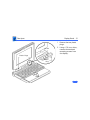
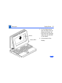
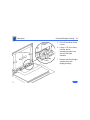
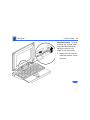
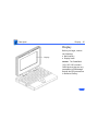
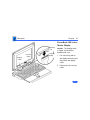
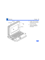
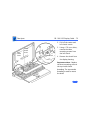
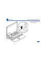
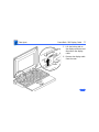
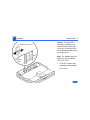
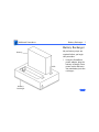
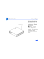
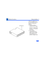
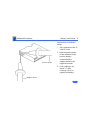
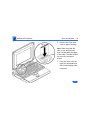
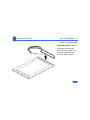
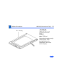
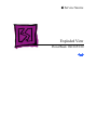
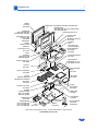
K Service Source
PowerBook 160/165/180
Series
PowerBook 160, PowerBook 165,
PowerBook 180
K Service Source
Basics
PowerBook 160/165/180
Basics
Overview - 1
Overview
This manual includes
complete repair procedures
for the PowerBook 160,
PowerBook 165, and
PowerBook 180..
Figure: PowerBook 160, 165, 180
Basics
Display Compatibility Matrix - 2
Display Compatibility Matrix
Inverter
Display Cable
Inverter Cable
Active Matrix
PB 180
661-0748
FSTN, Rev. A
PB 160/165
661-0745
630-6273
922-0820
922-0024
936-0106
922-0025
936-0106
Important: PowerBook 160/165/180 family includes two
displays—an active matrix and an FSTN display. Each of
these displays requires a compatible inverter and display
cable; the inverters, display cables, and displays are not
interchangeable. Before ordering one of these parts, refer to
the display matrix shown above.
K Service Source
Specifications
PowerBook 160/165/180
Specifications
Processor - 1
Processor
160 CPU
Motorola 68030 microprocessor
25 MHz
165 CPU
Motorola 68030 microprocessor
33 MHz
180 CPU
Motorola 68030 microprocessor
33 MHz
Coprocessor (180
Only)
Motorola 68882 floating-point math coprocessor
33 MHz
Specifications
Addressing
Processor - 2
32-bit internal registers
32-bit address bus
32-bit data bus
Specifications
Memory - 3
Memory
RAM
4 MB pseudostatic RAM (PSRAM) installed on the daughterboard
Expandable to 8 MB with 4 MB expansion card
Expandable to 14 MB with third-party PSRAM expansion cards
ROM
1 MB
PRAM
256 bytes of parameter memory
VRAM
128K of static video display memory
Clock/Calendar
CMOS custom chip with long-life lithium battery
Specifications
Disk Storage - 4
Disk Storage
Floppy Drive
19 mm high, internal, 1.4 MB Apple SuperDrive
Hard Drive
2.5 in. hard drives (many capacities)
Specifications
I/O Interfaces - 5
I/O Interfaces
Floppy Drive
SCSI
Apple Desktop Bus
DB-19 serial port for connecting external floppy drives
HDI-30 SCSI port with 1.5 MB/sec. transfer rate
Supports up to five external SCSI devices
Does not provide termination power
Connect SCSI device to computer with HDI-30 SCSI system cable.
Apple Desktop Bus (ADB) port (maximum of three ADB devices is
recommended)
200 mA maximum current draw for all ADB devices
Specifications
Serial
Sound
I/O Interfaces - 6
Two RS-422 serial ports; mini DIN-8 connectors
Monaural sound-in port
Stereo sound-out headphone jack, which plays CD audio tracks in
stereo and computer-generated sounds in mono
Video
Video-out port; 8 bit, 256 color video support
Supports Macintosh monitors up to 16-in. color and VGA monitors
Power Adapter
Power adapter port
Security
Slot for third-party security equipment
Modem
Slot for optional internal modem
Specifications
I/O Devices - 7
I/O Devices
Keyboard
Built-in keyboard with standard Macintosh layout
63 keys domestic; 64 keys ISO
Two-level tilt adjustment
Trackball
30 mm diameter, dual button
ADB interface
Microphone
Electret, omnidirectional
Output voltage of 4 mV, peak to peak
Specifications
Sound and Video - 8
Sound and Video
Sound Generator
160/165 Video
Display
180 Video Display
Apple sound chip provides 8-bit sound capable of driving stereo
headphones or other stereo equipment through the sound jack
8-bit sound input, sampled at 11 or 22 kHz
10 in. (254 mm) diagonal screen
Flat-panel, film-compensated supertwist nematic (FSTN) liquid
crystal display
CCFL on-demand backlight
16 shades of gray; 640 by 400 pixels
10 in. (254 mm) diagonal screen
Flat-panel, active-matrix liquid crystal display
CCFL on-demand backlight
16 shades of gray; 640 by 400 pixels
Specifications
Electrical - 9
Electrical
Main Battery
PRAM Battery
Power Adapter
Nickel cadmium (NiCad), 2.5 Ah
Provides 2-3 hours of usage before recharging
Recharge time: 3 hours
500 power cycles capacity
3 V lithium
110–220 VAC line voltage
17 W, 50–60 Hz
US, Japanese, United Kingdom, Australian, and European versions
Specifications
Physical - 10
Physical
Dimensions
Weight
Height: 2.25 in. (5.7 cm)
Width: 11.25 in. (28.6 cm)
Depth: 9.3 in. (23.6 cm)
6.8 lb. (3.1 kg) with battery
Specifications
Environmental - 11
Environmental
Operating
Temperature
Storage
Temperature
50–104° F (10-40° C)
-13 to 140° F (-25 to 60° C)
Relative Humidity
20–80% noncondensing
Altitude
0–15,000 ft. (0–4722 m)
Operational Altitude
0–10,000 ft. (0–3048 m)
Specifications
Other - 12
Other
Fax/Data Modem
Internal 2400-baud modem with fax send at 9600 baud (includes
fax send software)
300/1200/2400 bps transmission rates
Serial binary and asynchronous protocols
Error correction and data compression: MNP 4, 5 and V.42,
V.42bis
Specifications
Express Modem
SCSI Adapter
Other - 13
Internal 14,400-baud modem with fax send/receive at 9600
baud
300-14,400 bps data transmission rates
2400/4800/7200/9600 bps transmission rates
Full duplex operation; asynchronous or framed modes
Error correction: V.42 compliance (MNP 2-4)
Data compression: V.42bis (4 to 1 compression) and MNP-5 (2
to 1 compression)
Requires 300K of system RAM
Enables connection between PowerBook computer and desktop
Macintosh (PowerBook appears as a hard drive on the desktop
K Service Source
Troubleshooting
PowerBook 160/165/180
Troubleshooting
General/ - 1
General
The Symptom Charts included in this chapter will help you
diagnose specific symptoms related to your product. Because cures
are listed on the charts in the order of most likely solution, try
the first cure first. Verify whether or not the product continues to
exhibit the symptom. If the symptom persists, try the next cure.
(Note: If you have replaced a module, reinstall the original module
before you proceed to the next cure.)
If you are not sure what the problem is, or if the Symptom Charts
do not resolve the problem, refer to the Flowchart for the product
family.
For additional assistance, contact Apple Technical Support.
Troubleshooting
Power Manager Reset/ - 2
Power Manager Reset
Reset the power manager if
• The battery and power adapter are proven good, but the
computer will not power on.
• The computer will not reset after a system crash.
To
1
2
3
reset the power manager in a PowerBook 160/165/180
Remove the AC adapter and the battery.
Let the unit sit without power hooked up for 3–5 minutes.
Reinstall the battery and, if necessary, reconnect the AC
adapter.
4 Turn on the computer.
Troubleshooting
Power Manager Reset/ - 3
If this does not reset the power manager,
5 Remove the AC adapter and the battery.
6 Let the unit sit without power hooked up for 3–5 minutes.
7 Using two paper clips, simultaneously hold down the reset
and interrupt buttons for 5–10 seconds.
8 Reinstall the battery and, if necessary, reconnect the AC
adapter.
9 Turn on the computer.
Troubleshooting
Symptom Charts/Startup - 4
Symptom Charts
Startup
RAM failure occurs
(eight-tone error
chord sequence
sounds after startup
chord)
1
2
3
4
Reseat PSRAM expansion card and check connection.
Replace PSRAM expansion card.
Replace daughterboard.
Replace motherboard.
Hardware failure
occurs (four-tone
error chord sequence
sounds after startup
chord)
1
Disconnect hard drive data cable and restart computer. If
startup sequence is normal, reconnect cable and retest.
Replace hard drive.
Disconnect floppy drive cable and restart computer. If
startup sequence is normal, reconnect cable and retest.
Replace floppy drive.
Replace motherboard.
2
3
4
5
Troubleshooting
Symptom Charts/Startup - 5
Startup
Screen displays
checkerboard pattern;
no startup chime
1
2
3
4
Reseat RAM expansion card.
Replace RAM expansion card.
Replace daughterboard.
Reseat display cable.
Troubleshooting
Symptom Charts/Power - 6
Power
Screen is blank;
computer doesn’t
respond
1
2
3
4
5
6
7
8
9
Restart computer.
Connect power adapter and restart computer in 3-4 minutes.
Try known–good, charged main battery.
Check all interconnect board, daughterboard, and
motherboard connections.
Reset the power manager.
Replace keyboard.
Replace interconnect board.
Replace daughterboard.
Replace motherboard.
Troubleshooting
Symptom Charts/Power - 7
Power
After you remove
main battery, some
Control Panel
settings are different
1
2
3
4
Check cables.
Replace interconnect board.
Replace daughterboard.
Replace motherboard.
Power adapter is
plugged in, but
battery DA does not
indicate charger is
connected
1
2
3
4
5
6
This is normal for fully charged battery.
Check battery charger connection.
Try known-good, charged main battery.
Try known-good power adapter.
Check battery thermistor cable connection.
Replace motherboard.
Troubleshooting
Symptom Charts/Power - 8
Power
Low-power warning
appears
1
2
3
4
5
6
Recharge battery or attach power adapter.
Verify that peripherals are low-power.
Remove external devices or connect power adapter.
Try known-good, charged main battery.
Try known-good power adapter.
Replace motherboard.
Computer runs when
plugged into wall
outlet but not on
battery power;
battery voltage is
within tolerance
1
Reseat battery to make sure it is mating with contacts on
motherboard.
If motherboard includes removable fuse, replace fuse.
Replace motherboard.
Return computer to Apple.
2
3
4
Troubleshooting
Symptom Charts/Video - 9
Video
Pixel is always white
PowerBook 180
If there are more than five voids (pixels that are always white),
or two or more voids within one inch of each other, replace
display (CPRC/international repairers only) or return computer
to Apple.
PowerBooks 160 and 165
Replace display.
Pixel is always black
PowerBook 180
Replace display (CPRC/international repairers only) or return
computer to Apple.
PowerBooks 160 and 165
Replace display.
Troubleshooting
Symptom Charts/Video - 10
Video
Row or partial row of
pixels never comes
on (white line)
PowerBook 160/165
1 Check cables.
2 Replace display cable.
3 Replace display. If PowerBook has serial number below
FC247xxxxxx or CK247xxxxxx, replace both display and
daughterboard. (Do not replace Rev. B daughterboard.)
4 Replace interconnect board.
PowerBook 180
5 Check cables.
6 Replace display cable.
7 Replace display (CPRC/international repairers only) and
install System Enabler, v. 1.01.
8 Replace interconnect board.
9 Return computer to Apple.
Troubleshooting
Symptom Charts/Video - 11
Video
Row or partial row of
pixels is always on
(black line)
PowerBook 160/165
1 Check cables.
2 Replace display cable.
3 Replace display.
4 Replace interconnect board.
PowerBook 180
5 Check cables.
6 Replace display cable.
7 Replace interconnect board.
8 Replace display (CPRC/international only) or return
computer to Apple.
Troubleshooting
Symptom Charts/Video - 12
Video
Thin white line is
always on at middle of
screen
PowerBook160/165
Thin white line is normal.
PowerBook 180
Replace display (CPRC/international repairers only) or return
computer to Apple.
Troubleshooting
Symptom Charts/Video - 13
Video
Display is very light
or totally white
1
2
3
4
5
6
7
8
9
Adjust screen contrast.
Check display cable, inverter board, interconnect board,
daughterboard, and motherboard connections.
Replace inverter board.
Replace interconnect board.
Replace display cable.
PowerBook 160/165: Replace display.
Replace daughterboard.
Replace motherboard.
PowerBook 180: Replace display (CPRC/international
repairers only) or return computer to Apple.
Troubleshooting
Symptom Charts/Video - 14
Video
Rainbow colors
visible from extreme
viewing angles
PowerBook 160/165
Such colors are normal for FSTN screens.
Screen brightness is
not uniform
PowerBook 160/165
Irregularity in screen brightness is normal. Adjust contrast and
brightness to diminish effect.
PowerBook 180:
Replace display (CPRC/international repairers only) or return
computer to Apple.
Troubleshooting
Symptom Charts/Video - 15
Video
Display stopped
working or dimmed
but is fine now
PowerBook 160/165
If temperature is in the approximate range of under 5 or over 40
degrees centigrade, this reaction is normal.
Troubleshooting
Symptom Charts/Video - 16
Video
Backlight doesn’t
operate
1
2
Verify that cables are not pinched or severed.
Check display cable, inverter board, interconnect board,
daughterboard, and motherboard connections.
3 Replace inverter board.
4 Replace inverter display cable.
5 Replace interconnect board.
6 Replace display cable.
7 PowerBook 160/165: Replace display.
8 Replace daughterboard.
9 Replace motherboard.
10 PowerBook 180: Replace display (CPRC/international
repairers only) or return computer to Apple.
Troubleshooting
Symptom Charts/Video - 17
Video
Screen goes blank
1
2
3
4
Press any key to wake computer from system sleep.
Check display cable connection.
Reseat daughterboard.
Replace daughterboard.
Troubleshooting
Symptom Charts/Video - 18
Video
No display, but
computer appears to
operate correctly
1
2
Adjust screen contrast.
Check display cable, inverter board, interconnect board,
daughterboard, and motherboard connections.
3 Connect power adapter.
4 Replace inverter board.
5 Replace interconnect board.
6 Replace display cable.
7 PowerBook 160/165: Replace display.
8 Replace daughterboard.
9 Replace motherboard.
10 PowerBook 180: Replace display (CPRC/international
repairers only) or return computer to Apple.
Troubleshooting
Symptom Charts/Video - 19
Video
Audio and video
present, but internal
floppy drive does not
operate
1
2
3
4
5
6
Try known-good floppy disk.
Check floppy drive cable connection.
Replace floppy drive cable.
Replace floppy drive.
Replace daughterboard.
Replace motherboard.
Troubleshooting
Symptom Charts/Hard Drive - 20
Hard Drive
Internal hard drive
does not operate
1
2
3
4
5
6
Disconnect external SCSI devices.
Check internal hard drive cable connection.
Use HD SC Setup to reinitialize drive.
Replace internal hard drive cable.
Replace internal hard drive.
Replace motherboard.
Troubleshooting
Symptom Charts/Floppy Drive - 21
Floppy Drive
Audio and video
present, but internal
floppy drive does not
operate
1
2
3
4
5
6
Try known-good floppy disk.
Check floppy drive cable connection.
Replace floppy drive cable.
Replace floppy drive.
Replace daughterboard.
Replace motherboard.
Disk ejects while
booting; display
shows Mac icon with
blinking X
1
2
3
4
5
6
Try known-good system disk.
Verify that trackball or mouse button is not stuck.
Check floppy drive cable connection.
Replace floppy drive cable.
Replace floppy drive.
Replace motherboard.
Troubleshooting
Symptom Charts/Floppy Drive - 22
Floppy Drive
Disk does not eject
Disk initialization
fails
1
2
3
4
5
6
7
Switch off system and hold mouse button down while you
switch system on.
Insert opened paper clip into hole beside drive.
Check floppy drive cable connection.
Replace floppy drive cable.
Replace floppy drive.
Replace daughterboard.
Replace motherboard.
1
2
3
4
5
Try known-good floppy disk.
Install inverter shield (if absent).
Check floppy drive cable connection.
Replace floppy drive cable.
Replace floppy drive.
Troubleshooting
Symptom Charts/Floppy Drive - 23
Floppy Drive
Read/write/copy
error
1
2
3
4
5
Try known-good floppy disk.
Install inverter shield if absent.
Check floppy drive cable connection.
Replace floppy drive cable.
Replace floppy drive.
Troubleshooting
Symptom Charts/Peripherals - 24
Peripherals
After you connect
external SCSI device,
computer does not
boot
1
2
3
4
5
6
7
Cursor does not move
when you are using
trackball
1
2
3
4
Switch on external SCSI device before starting computer.
Check cable connections.
Verify that standard Apple terminator terminates SCSI chain
at beginning and end.
Verify that SCSI select switch setting on external device is
unique.
Verify operation of internal hard drive.
Try known-good external SCSI device.
Replace motherboard.
Restart computer.
Check cables.
Check interconnect board, daughterboard, and motherboard
connections.
Try low-power mouse. If cursor moves, replace trackball or
keyboard.
Troubleshooting
Symptom Charts/Peripherals - 25
Peripherals
Cursor intermittently
does not move or
moves erratically
1
2
3
Replace interconnect board.
Replace daughterboard.
Replace motherboard.
1
2
3
4
5
6
7
Restart computer.
Clean ball and rollers of trackball.
Check cables.
Replace trackball.
Replace keyboard.
Replace interconnect board.
Replace motherboard.
Troubleshooting
Symptom Charts/Peripherals - 26
Peripherals
Cursor moves, but
clicking trackball
button has no effect
1
2
3
4
5
6
7
Restart computer.
Check interconnect board, daughterboard, and motherboard
connections.
Replace trackball.
Replace keyboard.
Replace interconnect board.
Replace daughterboard.
Replace motherboard.
Cursor does not move
when you are using
mouse
1
2
3
4
5
Check mouse connection to ADB port.
Restart computer.
Clean mouse ball and inside mouse.
Replace mouse.
Replace motherboard.
Troubleshooting
Symptom Charts/Peripherals - 27
Peripherals
No response to any
key on keyboard
Known-good directconnect printer does
not print
1
2
3
4
5
Reset power manager.
Check connections of keyboard to interconnect board, and
interconnect board to daughterboard.
Replace keyboard.
Replace interconnect board.
Replace daughterboard.
1
2
3
4
5
6
7
Verify that System is 7.1 or later.
Verify that Chooser and Control Panel settings are correct.
Check cables.
Replace printer interface cable.
Try known-good printer.
Replace daughterboard.
Replace motherboard.
Troubleshooting
Symptom Charts/Peripherals - 28
Peripherals
Known-good network
printer does not print
Device connected to
external modem port
doesn’t work
1
2
3
4
5
6
7
Verify that System is 7.1 or later.
Verify that Chooser and Control Panel settings are correct.
Check cables.
Replace printer interface cable.
Try known-good printer. If printer works, troubleshoot
network. Refer to Networks manual.
Replace daughterboard.
Replace motherboard.
1
2
3
4
5
6
Verify that External Modem is selected in CDEV.
Verify that System is 7.1 or later.
Check cables.
Test device with known-good computer.
Replace daughterboard.
Replace motherboard.
Troubleshooting
Symptom Charts/Peripherals - 29
Peripherals
I/O devices are
unrecognized or
garbage is
transmitted or
received
1
2
3
4
5
6
7
Verify that System is 7.1 or later.
Check cables.
Verify that SCSI device has standard Apple terminator.
Verify that SCSI select switch setting on external device is
unique.
Test device with known-good computer.
Replace daughterboard.
Replace motherboard.
Troubleshooting
Symptom Charts/Internal Modem - 30
Internal Modem
Internal modem
options do not appear
in CDEV
1
2
3
4
Remove and reseat modem card.
Verify that System is 7.1 or later.
Replace modem card.
Replace motherboard.
Modem does not
respond properly to
AT command set
instructions
1
Verify that baud rate and data format settings of
communications application are compatible with internal
modem and remote modem.
Check phone cord connection and operation.
Remove and reseat modem card.
Verify that System is 7.1 or later.
Replace modem card.
2
3
4
5
Troubleshooting
Symptom Charts/Internal Modem - 31
Internal Modem
Strange mix of
characters appears
on screen
1
2
3
4
5
6
7
Verify that baud rate and data format settings of
communications application are compatible with internal
modem and remote modem.
Check phone cord connection and operation.
Remove and reseat modem card.
Verify that System is 7.1 or later.
Replace modem card.
Replace daughterboard.
Replace motherboard.
Modem interferes
with system sound
1
2
3
4
Remove and reseat modem card.
Replace modem board.
Replace interconnect card.
Replace motherboard.
Troubleshooting
Symptom Charts/Internal Modem - 32
Internal Modem
Modem does not
respond to incoming
call
1
2
3
4
If computer is in sleep mode, verify that Wake On Ring
option in CDEV is selected.
Check phone cord connection and operation.
Replace modem card.
Replace motherboard.
Modem has no sound
output
1
2
3
4
Verify that Control Panel volume setting is above 0.
Replace modem card.
Replace interconnect card.
Replace motherboard.
Modem connects but
does not communicate
with remote modem
1
Verify that remote modem needs error correction (error
correction is internal modem default).
Type “AT &Q0” to disable error correction.
2
Troubleshooting
Symptom Charts/Miscellaneous - 33
Miscellaneous
Screen goes blank and
computer shuts down
every few minutes
Adjust sleep delays in Control Panel or connect power adapter.
Application seems to
run slower after few
seconds
1
2
Hard drive is slow to
respond, or screen
goes blank too often
Adjust sleep delays in Control Panel or connect power adapter.
Disable System Rest. (See owner’s manual.)
Connect power adapter.
Troubleshooting
Symptom Charts/Miscellaneous - 34
Miscellaneous
No sound from
speaker
1
2
3
4
5
6
Verify that volume setting in Control Panel is above 0.
Verify that no external speaker is plugged in.
Check connections of speaker to interconnect board,
interconnect board to daughterboard, and daughterboard to
motherboard.
Replace interconnect board.
Replace daughterboard.
Replace motherboard.
K Service Source
Take Apart
PowerBook 160/165/180
Take Apart
Main Battery - 1
Main Battery
Before you begin,
disconnect the power
adapter.
Note: This procedure also
covers removal of the main
battery door.
Important: Before removing
the main battery, use the
Macintosh Shut Down
command. Otherwise, all
RAM contents will be lost.
Main Battery
Take Apart
Main Battery - 2
The main
battery contains toxic
materials. Review
battery-handling and
disposal instructions in
Bulletins/Safety.
±Warning:
1
2
Slide open the battery
door.
Using the battery door as
a handle, pull out the
main battery.
Take Apart
Main Battery - 3
3
4
End Tab
Slide the battery door
completely open.
Pull the end tab until it
releases and remove the
door from the battery.
Take Apart
I/O Door - 4
I/O Door
No preliminary steps are
required before you begin
this procedure.
Caution: The PowerBook
160/165/180 contains
CMOS devices that are very
susceptible to ESD damage.
Review the ESD precautions
in Bulletins/Safety.
I/O Door
Take Apart
I/O Door - 5
1
2
Right Door
Peg
Open the I/O door.
Carefully bend the door
so that the middle bows
downward and unhinge
the two bottom door pegs.
Take Apart
Top Case - 6
Top Case
Top Case
Before you begin, remove
the following:
• Main battery
• I/O door
Caution: The PowerBook
160/165/180 contains
CMOS devices that are very
susceptible to ESD damage.
Review the ESD precautions
in Bulletins/Safety.
Take Apart
Top Case - 7
Note: Use a T-8 torx driver
to remove the small screw
from the rear connector
panel and a T-10 torx
driver to remove the other
case screws.
1
Remove the five torx
screws from the bottom
case.
Take Apart
Top Case - 8
2
3
Interconnect
Cable
Lift the back of the top
case and disconnect the
interconnect cable.
Lift off the top case and
unhook the two tab
fasteners from the front
of the bottom case.
Replacement Caution:
When connecting the display
cable connector, fold the
cable as shown. If it is not
folded correctly, the cable
could short.
Tab Fastener
Take Apart
Trackball Assembly - 9
Trackball
Assembly
Trackball
Assembly
Before you begin, remove
the following:
• Main battery
• I/O door
• Top case
Caution: The PowerBook
160/165/180 contains
CMOS devices that are very
susceptible to ESD damage.
Review the ESD precautions
in Bulletins/Safety.
Take Apart
Trackball
Ribbon Cable Locking
Tab
Trackball Assembly - 10
Caution: The trackball
ribbon cable is fragile and
should be handled with care.
1
Pull out the locking tab
on the trackball
connector and remove
the trackball ribbon
cable.
Take Apart
Trackball Assembly - 11
2
Using a T-8 torx driver,
remove the two mounting
screws and lift the
trackball assembly
from the top case.
Take Apart
Keyboard - 12
Keyboard
Keyboard
Before you begin, remove
the following:
• Main battery
• I/O door
• Top case
• Trackball assembly
Caution: The PowerBook
160/165/180 contains
CMOS devices that are very
susceptible to ESD damage.
Review the ESD precautions
in Bulletins/Safety.
Take Apart
Keyboard - 13
Caution: The keyboard
ribbon cables are fragile and
should be handled with care.
Keyboard
Ribbon Cables
1
Lift the locking tabs on
the two keyboard
connectors and remove
the keyboard ribbon
cables.
Take Apart
Keyboard - 14
2
Using a T-8 torx driver,
remove the seven
mounting screws and
lift the keyboard from
the top case.
Take Apart
Inverter Board - 15
Inverter Board
Inverter Board
Before you begin, remove
the following:
• Main battery
• I/O door
• Top case
Caution: The PowerBook
160/165/180 contains
CMOS devices that are very
susceptible to ESD damage.
Review the ESD precautions
in Bulletins/Safety.
Take Apart
Inverter Board - 16
Important: The PowerBook
160/165 and PowerBook
180 displays require
different inverter boards.
Refer to the Service Source
parts database for the
correct part number for
each board.
Take Apart
Inverter Board - 17
1
Inverter
Shield
Inverter
Board
Inverter
Cable
Remove the two
mounting screws.
Note: Do not remove the
inverter shield from the
inverter board.
2
3
Pull the inverter board
and attached shield
straight up and off the
connector on the
interconnect board.
Disconnect the inverter
cable.
Take Apart
Brightness Pot
Inverter Board - 18
Contrast Pot
Inverter
Board
Actuator
Actuator
Replacement Note: Be sure
to align the brightness and
contrast pots on the inverter
board with the plastic
actuators on the top case. It
is easiest to align the pots
and actuators if you set both
to their extreme outer
positions.
Take Apart
Inverter Board - 19
Inverter Shield
Inverter
Board
Replacement Note: If you
are replacing the inverter
board, order both the
inverter board and the
inverter shield. Install the
new shield on the board
before replacing it. Do not
reuse the original inverter
shield.
Take Apart
Interconnect Board - 20
Interconnect Board
Before you begin, remove
the following:
• Main battery
• I/O door
• Top case
• Inverter board
Caution: The PowerBook
160/165/180 contains
CMOS devices that are very
susceptible to ESD damage.
Review the ESD precautions
in Bulletins/Safety.
Interconnect Board
Take Apart
Interconnect Board - 21
The
interconnect board contains
hazardous materials.
Return bad interconnect
boards to Apple for proper
disposal.
±Warning:
J5 Connector
J3 Connector
Caution: The keyboard and
display cables are fragile
and should be handled with
care.
1
Lift the locking tabs on
connectors J5 and J3 and
remove the keyboard
ribbon cables.
Take Apart
Interconnect Board - 22
Note: The display cable will
not come entirely out of the
connector until you remove
the interconnect board from
the top case.
2
J2 Connector
Pull out the locking tab
on connector J2 and ease
the display cable out of
the connector as far as
the cable will go.
Replacement Note: Connect
the display cable before
replacing the interconnect
board.
Take Apart
Interconnect Board - 23
3
Using a T-8 torx driver,
remove the two mounting
screws and lift the
interconnect board from
the top case.
Take Apart
Actuators - 24
Actuators
Actuators
Before you begin, remove
the following:
• Main battery
• I/O door
• Top case
• Inverter board
Caution: The PowerBook
160/165/180 contains
CMOS devices that are very
susceptible to ESD damage.
Review the ESD precautions
in Bulletins/Safety.
Take Apart
Actuators - 25
1
2
Pull up the contrast
actuator, rotate it
toward the display, and
remove the actuator
from the top case.
Repeat for the
brightness actuator.
Take Apart
Elevation Feet - 26
Elevation Feet
Before you begin, remove
the following:
• Main battery
• I/O door
• Top case
Elevation Foot
Elevation Foot
Caution: The PowerBook
160/165/180 contains
CMOS devices that are very
susceptible to ESD damage.
Review the ESD precautions
in Bulletins/Safety.
Take Apart
Elevation Feet - 27
1
2
Spring
Clip
Elevation
Foot
Using a T-8 torx driver,
remove the torx screw,
washer, and spring clip
from the inside of the
elevation foot.
Pull off the elevation
foot.
Take Apart
Daughterboard - 28
Daughterboard
Before you begin, remove
the following:
• Main battery
• I/O door
• Top case
• PSRAM expansion card
(if present)
Caution: The PowerBook
160/165/180 contains
CMOS devices that are very
susceptible to ESD damage.
Review the ESD precautions
in Bulletins/Safety.
Daughterboard
Take Apart
Daughterboard - 29
Daughterboard
Motherboard
Logic Board
Take-Apart
Tool
1
Using a T-8 torx driver,
remove the four
daughterboard mounting
screws.
Caution: Always use the
logic board take-apart tool
to separate the
daughterboard connector
from the motherboard
connector. Trying to
disconnect the
daughterboard from the
motherboard by rocking or
peeling the boards apart
damages the connectors.
Take Apart
Daughterboard - 30
2
U27
Using the Apple logic
board take-apart tool,
disconnect the
daughterboard from the
motherboard.
Replacement Note: If you
are replacing a defective
daughterboard, be aware
that the PowerBook 160/
165/180 daughterboards
are very similar. To
differentiate
daughterboards, check the
underside of the board.
PowerBook 180
daughterboards have an FPU
chip soldered at location
Take Apart
Daughterboard - 31
U27; PowerBook 160/165
boards do not.
To further differentiate
PowerBook 160 and 165
daughterboards, check the
underside for the following
resistors:
• PowerBook 160
daughterboard
R38 resistor: installed
R39 resistor: not
installed
• PowerBook 165
daughterboard
R38 resistor: not
installed
Take Apart
Daughterboard - 32
R39 resistor: installed
For daughterboard part
numbers, refer to the
Service Source parts
database.
Heat Sinks
Heat Sink
Daughterboard
Replacement Note: The
green heat sinks attached to
the daughterboard are made
of delicate heat-conducting
material. If they are missing
or damaged, they must be
replaced.
Replacement Note: To
replace a damaged heat sink,
carefully peel it from the
daughterboard. Select the
Take Apart
Daughterboard - 33
appropriately sized heat
sink from the heat sink kit
(part number 076-0069),
and gently press the part
into place.
Replacement Caution: Make
sure the heat sink is placed
exactly as shown in the
illustration. The heat sink
should not hang over the side
of the component it is
covering, or it may short
the component leads.
Take Apart
Daughterboard - 34
Sound Jack Insulator
Sound Jack
Assembly
Motherboard
Replacement Note: If you
are replacing a defective
daughterboard in a
PowerBook 160/180
within the serial number
range FC233xxxxxx
through FC241xxxxxx, you
must also replace the sound
jack insulator on the
motherboard.
Take Apart
Daughterboard - 35
Replacement Note: To
replace the sound jack
insulator, carefully peel off
the original insulator.
Remove the paper backing on
the revised insulator (part
number 922-0591), and
gently press it into place.
Replacement Caution: Make
sure the new insulator sits
in exactly the same position
as the original insulator.
Take Apart
Motherboard - 36
Motherboard
Before you begin, remove
the following:
• Main battery
• I/O door
• Top case
• PSRAM expansion card
(if present)
• Daughterboard
• Modem card (if present)
Caution: The PowerBook
160/165/180 contains
CMOS devices that are very
susceptible to ESD damage.
Review the ESD precautions
in Bulletins/Safety.
Motherboard
Take Apart
Motherboard - 37
Hard Drive
Cable
Floppy Drive Cable
Thermistor Cable
Caution: The hard drive,
floppy drive, and thermistor
cables are fragile and
should be handled with care.
1
2
Locking Tab
Locking
Tab
Lift the locking tabs and
remove the floppy drive
and thermistor cables.
Remove the hard drive
cable.
Take Apart
Motherboard - 38
Hex-Head Screw
Motherboard
3
Remove the two hexhead screws and lift the
motherboard from the
bottom case.
Take Apart
Hard Drive - 39
Hard Drive
Before you begin, remove
the following:
• Main battery
• I/O door
• Top case
• Modem card (if present)
• Daughterboard
Caution: The PowerBook
160/165/180 contains
CMOS devices that are very
susceptible to ESD damage.
Review the ESD precautions
in Bulletins/Safety.
Hard Drive
Take Apart
Hard Drive - 40
Hard Drive
Cable
Caution: The hard drive
cable is fragile and should be
handled with care.
1
Disconnect the hard
drive cable from the
motherboard.
Take Apart
Hard Drive - 41
2
Retainer
Latch
Drive Retainer
3
Using a T-8 torx driver,
remove the five screws
from the drive retainer.
Using a jeweler’s
screwdriver, release the
drive retainer latch and
remove the retainer.
Take Apart
Hard Drive - 42
4
5
Release Loop
Lift the hard drive from
the case.
Pull the release loop and
disconnect the hard drive
cable.
Note: If the cable does not
have a release loop, gently
pry the cable from the drive
with a screwdriver.
Take Apart
Hard Drive - 43
Replacement Note: Drive
retainers for 17-mm-high
and 19-mm-high hard
drives are not
interchangeable. Check the
height of the replacement
drive and use the
appropriate drive retainer.
If you are upgrading from a
40 MB to 80 MB hard drive,
use the ridged, 17-mm
retainer that shipped with
the 80 MB hard drive.
Take Apart
Hard Drive - 44
Replacement Note: For
information on returning
drives, cables, and carriers
to Apple, refer to Additional
Procedures in the Hard
Drives chapter.
Take Apart
Floppy Drive - 45
Floppy Drive
Floppy Drive
Before you begin, remove
the following:
• Main battery
• I/O door
• Top case
• Modem card (if present)
• Daughterboard
Caution: The PowerBook
160/165/180 contains
CMOS devices that are very
susceptible to ESD damage.
Review the ESD precautions
in Bulletins/Safety.
Take Apart
Mylar Insulator
Floppy Drive - 46
Note: Follow this procedure
if a rectangular green heat
sink extends over the floppy
drive.
1
Heat Sink
2
Remove the screw
holding the heat sink
over the floppy drive and
lift off the heat sink.
Remove the mylar
insulator attached to the
drive retainer.
Take Apart
Floppy Drive - 47
Caution: The floppy drive
cable is fragile and should be
handled with care.
Floppy Drive Cable
Locking
Tab
3
Lift the locking tab and
disconnect the floppy
drive cable from the
motherboard.
Take Apart
Floppy Drive - 48
4
Retainer
Latch
5
Drive Retainer
Using a T-8 torx driver,
remove the five torx
screws from the drive
retainer.
Using a jeweler’s
screwdriver, release the
drive retainer latch and
remove the retainer.
Take Apart
Floppy Drive - 49
6
Locking Tab
7
Slide the floppy drive
back and lift it from the
bottom case.
Using a jeweler’s
screwdriver, push out
the locking tab and
remove the floppy drive
cable from the drive.
Replacement Caution: When
connecting the floppy drive
cable connector, fold the
cable as shown. If it is not
folded correctly, the cable
could short.
Take Apart
Display Bezel - 50
Display Bezel
Display Bezel
Before you begin, remove
the main battery.
Caution: The PowerBook
160/165/180 contains
CMOS devices that are very
susceptible to ESD damage.
Review the ESD precautions
in Bulletins/Safety.
Take Apart
Display Bezel - 51
1
Screw
Plastic Plugs
Plastic
Plug
2
Remove the two plastic
plugs.
Using a T-8 torx driver,
remove the two bezel
mounting screws from
the display.
Take Apart
Display Bezel - 52
3
Display
Display Bezel
4
Pull the display bezel
down and away from the
display and release the
bezel from the mounting
tabs at the top and sides
of the display.
Lift the bezel off the
display.
Take Apart
Clutches/Display Housing - 53
Display Housing
Clutches/Display
Housing
Before you begin, remove
the following:
• Main battery
• Display bezel
Right Clutch
Left Clutch
Caution: The PowerBook
160/165/180 contains
CMOS devices that are very
susceptible to ESD damage.
Review the ESD precautions
in Bulletins/Safety.
Take Apart
Clutches/Display Housing - 54
Note: This topic includes
take apart procedures for
the left and right clutch
assemblies and the display
housing.
Display Housing
EMI Shield
Display
1
2
3
4
Cover the keyboard with
a clean cloth or sheet of
paper.
Using a T-8 torx driver,
remove the four display
mounting screws.
Remove the display
from the housing and
EMI shield.
Place the display facedown on the keyboard.
Take Apart
Clutches/Display Housing - 55
Inverter
Cable
5
6
Clutch Covers
Right
Clutch
7
Pull off the three clutch
covers.
Using a T-8 torx driver,
remove the six
mounting screws from
the left and right
clutches.
Remove the left and right
clutches from the
display housing.
Take Apart
Clutches/Display Housing - 56
Replacement Note: Replace
the short mounting screws
in the top-inside clutch
threadings. The top-outside
threadings are used to mount
the bezel.
Replacement Note: To avoid
pinching the inverter cable,
route the cable behind the
top-right corner of the
hinge on the right clutch.
Take Apart
Clutches/Display Housing - 57
Display Housing
EMI Shield
8
Remove the display
housing and EMI shield
from the case.
Take Apart
Inverter Cable - 58
Inverter Cable
Inverter Cable
Before you begin, remove
the following:
• Main battery
• I/O door
• Top case
• Inverter board
• Display bezel
Caution: The PowerBook
160/165/180 contains
CMOS devices that are very
susceptible to ESD damage.
Review the ESD precautions
in Bulletins/Safety.
Take Apart
Center
Clutch
Cover
Inverter Cable - 59
Right
Clutch
Cover
Inverter
Cable
Right
Clutch
1
2
3
Pull off the center and
right clutch covers.
Using a T-8 torx driver,
remove the three
mounting screws from
the right clutch.
Remove the clutch from
the display housing.
Replacement Note: Replace
the short mounting screw in
the top-inside clutch
threading. The top-outside
threading is used to mount
the bezel.
Take Apart
Inverter Cable - 60
Replacement Note: To avoid
pinching the inverter cable,
route the cable behind the
top-right corner of the
hinge on the right clutch.
4
Disconnect the inverter
cable and remove it from
the case.
Take Apart
Display - 61
Display
Display
Before you begin, remove
the following:
• Main battery
• Display bezel
Caution: The PowerBook
160/165/180 contains
CMOS devices that are very
susceptible to ESD damage.
Review the ESD precautions
in Bulletins/Safety.
Take Apart
Display - 62
Note: This topic includes
separate procedures for
removing the PowerBook
160/165 FSTN display and
the PowerBook 180 activematrix display.
Note: The PowerBook 180
active matrix display
module is available to CPRC
and international repairers
only.
Take Apart
Display - 63
Display Housing
PowerBook 160/165
FSTN Display
EMI Shield
Display
Caution: The display cable
is fragile and should be
handled with care.
1
2
3
Cover the keyboard with
a clean cloth or sheet of
paper.
Using a T-8 torx driver,
remove the four display
mounting screws.
Remove the display
from the housing and
EMI shield.
Take Apart
Display - 64
4
5
Locking
Tab
Adhesive
Adhesive
Place the display facedown on the keyboard.
Lift the locking tab on
the display connector and
disconnect the display
cable.
Take Apart
Display - 65
6
Caution: The PowerBook
160/165 display cable
is attached to the display
with adhesive near the
connector and backlight
ends of the cable.
Carefully pry the cable
off the display at these
two points.
Gently detach the
display cable from the
back of the display.
Take Apart
Display - 66
Inverter
Cable
7
8
Inverter Cable
Backlight Cable
Right
Clutch
Disconnect the inverter
cable from the display
backlight cable.
Remove the display.
Replacement Note: To avoid
pinching the inverter cable,
route the cable behind the
top-right corner of the
hinge on the right clutch.
Take Apart
Display - 67
PowerBook 180 ActiveMatrix Display
Locking
Tab
Display
Cable
Inverter
Cable
Display
Cable
Caution: The display cable
is fragile and should be
handled with care.
1
2
Lift the locking tab on
the display connector and
disconnect the display
cable.
Disconnect the inverter
cable.
Take Apart
Display - 68
3
Housing
EMI Shield
4
Display
Using a T-8 torx driver,
remove the four display
mounting screws.
Remove the display
from the housing and
EMI shield.
Take Apart
Display - 69
Inverter
Cable
Right
Clutch
Replacement Note: To avoid
pinching the inverter cable,
route the cable behind the
top-right corner of the
hinge on the right clutch.
Take Apart
PB 160/165 Display Cable - 70
PB 160/165
Display Cable
PowerBook 160/165
Display Cable
Before you begin, remove
the following:
• Main battery
• I/O door
• Top case
• Inverter board
• Interconnect board
• Display bezel
• PowerBook 160/165
• Display
Take Apart
PB 160/165 Display Cable - 71
Caution: The PowerBook
160/165 contains CMOS
devices that are very
susceptible to ESD damage.
Review the ESD precautions
in Bulletins/Safety.
Caution: The display cable
is fragile and should be
handled with care.
1
Ferrite Bead
Pry the display cable
ferrite bead from the
case.
Take Apart
PB 160/165 Display Cable - 72
2
Left
Clutch
Cover
3
Center
Clutch
Cover
Left Clutch
4
Pull off the center and
left clutch covers.
Using a T-8 torx driver,
remove the three
mounting screws from
the left clutch.
Remove the clutch from
the display housing.
Replacement Note: Replace
the short mounting screw in
the top-inside clutch
threading. The top-outside
threading is used to mount
the bezel.
Take Apart
PB 160/165 Display Cable - 73
5
Display
Cable
Remove the display cable
from the case.
Take Apart
PowerBook 180 Display Cable - 74
PowerBook 180
Display Cable
Before you begin, remove
the following:
• Main battery
• I/O door
• Top case
• Inverter board
• Interconnect board
• Display bezel
PowerBook 180
Display Cable
Di l
C bl
Take Apart
PowerBook 180 Display Cable - 75
Caution: The PowerBook
180 contains CMOS devices
that are very susceptible to
ESD damage. Review the ESD
precautions in Bulletins/
Safety.
Caution: The display cable
is fragile and should be
handled with care.
1
Ferrite Bead
Pry the display cable
ferrite bead from the
case.
Take Apart
PowerBook 180 Display Cable - 76
2
Left
Clutch
Cover
3
Center
Clutch
Cover
Left Clutch
4
Pull off the center and
left clutch covers.
Using a T-8 torx driver,
remove the three
mounting screws from
the left clutch.
Remove the clutch from
the display housing.
Replacement Note: Replace
the short mounting screw in
the top-inside clutch
threading. The top-outside
threading is used to mount
the bezel.
Take Apart
PowerBook 180 Display Cable - 77
Locking
Tab
5
6
Display
Cable
Lift the locking tab on
the display connector and
disconnect the display
cable.
Remove the display cable
from the case.
K Service Source
Upgrades
PowerBook 160/165/180
Upgrades
Modem Card - 1
Modem Card
Modem Card
Before you begin, remove
the following:
• Main battery
• I/O door
• Top case
Caution: The PowerBook
160/165/180 contains
CMOS devices that are very
susceptible to ESD damage.
Review the ESD precautions
in Bulletins/Safety.
Upgrades
Modem Port Cover
Release
Tabs
Modem Card - 2
Caution: If you install a
third-party modem card,
make sure that it does not
cover any of the heat sinks
on the daughterboard or over
the floppy drive.
Note: The modem card is an
option for the PowerBook
160/165/180.
1
Pinch the release tabs
and push out the modem
port cover.
Upgrades
Modem Card - 3
2
Modem
Modem Card Connector
J8 Connector
3
Connect the modem card
connector to
motherboard connector
J8.
Install the two mounting
screws.
Upgrades
Modem Card - 4
4
Modem Port
HD-30
SCSI Port
5
FCC Modem
Label
DOC Label
Affix the FCC modem
label to the inside of the
I/O door. Align the label
with the modem port.
Affix the DOC label to the
inside of the I/O door.
Align the label with the
HD-30 SCSI port.
Upgrades
PSRAM Expansion Card - 5
PSRAM
Expansion Card
Before you begin, remove
the following:
• Main battery
• I/O door
• Top case
Caution: The PowerBook
160/165/180 contains
CMOS devices that are very
susceptible to ESD damage.
Review the ESD precautions
in Bulletins/Safety.
PSRAM Expansion Card
Upgrades
PSRAM Expansion Card - 6
Caution: Handle the PSRAM
card by the edges only. Do
not touch any components on
the card.
Caution: If you install a
third-party expansion
card, do not remove or cover
up any of the heat sinks on
the daughterboard.
Operating the computer
without the heat sinks
significantly increases the
chance of daughterboard
failure.
Upgrades
PSRAM Expansion Card - 7
Caution: An incorrectly
installed PSRAM card could
damage the daugherboard.
Note that the expansion
connector and the PSRAM
card are keyed for proper
installation. Do not force
the card into the connector,
thereby defeating the key.
Caution: When installing
the card, press down on the
edge directly above the
connector. Be careful not to
apply pressure to any
components or you may
permanently damage the
card.
Upgrades
PSRAM Expansion Card - 8
PSRAM Expansion Card
PSRAM Expansion Card
Expansion
Connector
Expansion
Connector
1
Connect the PSRAM
expansion card to the
expansion connector on
the daughterboard.
Upgrades
PSRAM Expansion Card - 9
Note: To verify that the
upgrade is successful, check
the Total Memory message
(for systems with virtual
memory switched off) or the
Built-in Memory message
(for systems with virtual
memory switched on). The
memory size should be 4 MB
of soldered RAM plus the
RAM on the expansion card.
If the memory size is
incorrect, replace the
expansion card. If the
memory size is still
incorrect, send the
computer to Apple.
K Service Source
Additional Procedures
PowerBook 160/165/180
Additional Procedures
Battery Recharger - 1
Battery Recharger
No preliminary steps are
required before you begin
this procedure.
Battery
1
LED
Battery
Recharger
Using the PowerBook
power adapter, plug the
battery recharger into a
power outlet and insert
the main battery into the
recharger.
Additional Procedures
Battery Recharger - 2
2
Track the status of the
battery. If the LED is
• Yellow, the battery is
charging
• Green, the battery is
ready to use
• Off, the charger is
unplugged, the
battery is bad, the
power adapter is
defective, or the
charger is defective
Additional Procedures
SCSI Termination - 3
SCSI Termination
SCSI Terminator
No preliminary steps are
required before you begin
this procedure.
Note: The PowerBook 160/
165/180 does not provide
SCSI termination at the logic
board; remember to
terminate at the beginning
and end of the SCSI chain.
Use the standard Apple
terminator.
Single External SCSI Device
Additional Procedures
SCSI Termination - 4
When terminating SCSI
devices, follow these
guidelines:
• Add one terminator to a
single external SCSI
device, or
• Add one terminator to the
first device and another
to the last when there are
multiple devices.
Additional Procedures
Battery Handling - 5
Battery Handling
Main Battery
No preliminary steps are
required before you begin
this procedure.
Warning: The main
battery contains toxic
materials. Review battery
handling and disposal
instructions in Bulletins/
Safety.
±
Additional Procedures
Battery Handling - 6
Main Battery
Follow the guidelines on
this card and the next for
properly handling the
battery:
• Handle the battery
carefully. Do not drop,
puncture, disassemble,
mutilate, or incinerate
the battery.
• Fully charge a
replacement battery
before using it; Apple
ships batteries in a
partially charged state.
Additional Procedures
Battery Case
Battery Handling - 7
• Do not leave the battery
in the computer for
longer than two weeks
without plugging in the
power adaptor.
• Completely discharge and
then recharge the battery
once a month.
• Store the battery in the
protective battery case.
• Do not short-circuit the
battery terminals.
• Keep the battery in a
cool, dark place; do not
store it for longer than 6
months without
recharging.
Additional Procedures
Battery Verification - 8
Battery
Verification
Main Battery
Before you begin, remove
the main battery.
Note: The battery desk
accessory is a general
indicator of the battery
charge. Use a voltmeter to
determine the actual charge.
Refer to the procedure on
the next page.
The main
battery contains toxic
materials. Review battery
handling and disposal
±Warning:
Additional Procedures
Battery Verification - 9
instructions in Bulletins/
Safety.
1
2
Positive Probe
3
Negative Probe
Set a voltmeter to the 10
volts DC scale.
Hold the positive probe
of the voltmeter to the
positive battery
terminal and the
negative probe to the
negative terminal.
If the reading is not
above 5.7 volts,
recharge (first) or
replace the battery.
Additional Procedures
AC Adapter Verification - 10
AC Adapter
Verification
Negative
Probe
No preliminary steps are
required before you begin
this procedure.
1
2
Adapter
Plug
3
Positive
Probe
Plug the AC adapter into
a wall socket.
Set a voltmeter to the 10
volts DC scale.
Hold the positive probe
of the voltmeter to the
inside of the AC adapter
plug and the negative
probe to the outside of
the plug.
Additional Procedures
AC Adapter Verification - 11
4
If the reading is not 7.5–
7.9 volts, replace the
adapter.
Additional Procedures
Shim Installation - 12
Shim Installation
Shim
Before you begin, do the
following:
• Remove the main battery
• Remove the display bezel
Note: Some PowerBook
160/165/180 displays
may flicker, intermittently
go black, or display two
horizontal black lines. If
squeezing the right side of
the display bezel causes the
condition to improve or to
worsen, install a shim on
the display cable. The shim
improves the connection
Additional Procedures
Shim Installation - 13
between the connector
fingers and the cable
contacts.
Note: This topic includes
separate procedures for
installing a shim on the
PowerBook 160/165 and
PowerBook 180 display
cables.
Note: Do not install a shim
on a display cable stamped
with part number 9360108.
Additional Procedures
Shim Installation - 14
Housing
PowerBook 160/165
Display Cable
EMI Shield
Display
Caution: The display cable
is fragile and should be
handled with care.
1
2
3
Cover the keyboard with
a clean cloth or sheet of
paper.
Using a T-8 torx driver,
remove the four display
mounting screws.
Remove the display
from the housing and
EMI shield.
Additional Procedures
Shim Installation - 15
4
5
Locking
Tab
Place the display facedown on the keyboard.
Lift the locking tab on
the display connector and
disconnect the display
cable.
Additional Procedures
Shim Installation - 16
Shim
Cable
6
Remove the clear shim
from its paper backing.
Note: Make sure that the
shim is not wrinkled and
that it is flush with the edges
of the cable. The shim should
not cover the connector
traces.
7
Turn back the end of the
display cable and press
the shim onto the back
(the nonconductive
side) of the display cable
connector.
Additional Procedures
Shim Installation - 17
Locking
Tab
Display
Cable
PowerBook 180
Display Cable
Caution: The display cable
is fragile and should be
handled with care.
1
Lift the locking tab on
the display connector and
disconnect the display
cable.
Additional Procedures
Shim Installation - 18
2
Shim
Cable
Remove the clear shim
from its paper backing.
Note: Make sure that the
shim is not wrinkled and
that it is flush with the edges
of the cable. The shim should
not cover the connector
traces.
3
Press the shim onto the
back (the nonconductive
side) of the display cable
connector.
Additional Procedures
Rev. C Display Bulb - 19
Rev. C Display
Bulb
Rev. C Display
Before you begin, remove
the following:
• Main battery
• Display bezel
• Display
CCFL bulbs are
thin and break easily. Handle
them with care, especially
at the delicate solder joints
at the ends of the bulbs.
±Warning:
Additional Procedures
Rev. C Display Bulb - 20
Cables
Caution: Review the ESD
precautions in Bulletins/
Safety.
1
2
3
Place the display facedown on a soft
workbench pad.
Remove the two cables
from their channels.
Turn over the display.
Additional Procedures
Rev. C Display Bulb - 21
4
Bulb
Cover
Display Bulb
5
Remove the remaining
length of the cables
from the channels.
Using a #1 cross-tip
screwdriver, remove
the four self-threading
screws.
Replacement Caution:
Improperly installed selfthreading screws could
damage the display. Do not
overtighten them.
6
Remove the plastic
display bulb cover.
Additional Procedures
Rev. C Display Bulb - 22
7
Display Bulb
Remove the display bulb.
Replacement Note: When
replacing the new bulb,
make sure the cables are in
the same position as the
previous bulb’s cables.
Additional Procedures
Rev. C Display
AM Bulb (International Only) - 23
AM Bulb
(International
Only)
Note: CPRC and
international repairers only
should replace a bad
backlight bulb in the
PowerBook 180 activematrix display.
Additional Procedures
Backup Battery Verification - 24
Backup Battery Verification
The backup battery saves the PRAM and power management
information on the logic board when the computer is shut
down. To check that the backup battery is working, follow
the procedures below.
1
Set the date and time
3
Remove the main battery and disconnect the power
adaptor for 10 minutes.
2
4
5
Perform a Shut Down from the Apple Menu or Special
menu.
Connect the power adaptor, insert the battery, and power
on the computer.
If the date and time were lost, the backup battery may be
dead or discharged.
Additional Procedures
Backup Battery Verification - 25
6
7
To recharge the backup battery, leave the PowerBook
plugged in for 48 hours. It is ok to use it while it is
charging.
If the backup battery appears dead or will not charge,
replace the backup battery.
K Service Source
Exploded View
PowerBook 160/165/180
Exploded View
1
Display
Housing
922-0044
Display 661-0745 (PB 160/165),661-0748 (PB 180)
Display Bezel
922-0026 (PB 160), 922-1108 (PB 165),
922-0030 (PB 180)
EMI Shield
805-0138 (PB 160)
922-0543 (PB 165/180)
Rubber Plug 875-0112
Inverter Cable
936-0106
Brightness Actuator
815-1248
Elevation
Foot
815-1278 (Left)
922-1691 (Right)
PowerBook 160/165
Display Cable
922-0820
PowerBook
170/180
Display Cable
630-6273
External Battery
Recharger
076-0567
End Clutch Cover
815-1231
Clutch
Assembly
699-0497 (Left)
699-0498 (Right)
Trackball Assembly
661-1515
Drive Retainer
922-0009 (17 mm)
922-0006 (19 mm)
Center Clutch Cover
922-0029
I/O Door
922-1697
External Floppy
Drive
661-1651
Interconnect Board
661-0750
Inverter
922-0024 (PB 180)
922-0025 (PB 160/165)
Hard Drive*
661-1298
Keyboard*
661-0712
Modem
661-0786
Modem Port Cover
815-0578
PSRAM
Expansion Card
661-0715 (2 MB)
661-0790 (4 MB)
Motherboard
661-0746
Daughterboard
661-0744 (PB 160)
661-1016 (PB 165)
661-0747 (PB 180)
Floppy
Drive Cable
821-0655
HDA Cable
922-0027
Case Bottom
076-0872
Battery
Door
922-1700
Rubber Foot
815-1236
Battery
661-0013
Power Adapter*
922-0376
Z922-0043
Product family configurations may vary. For parts with asterisk (*), refer to parts list.
Power Book 160, 165, 180