1
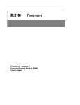
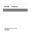
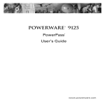
Powerware® 9125 Two-in-One
PowerPass®
User’s Guide
For use with the Powerware 9125 Two-in-One
700–2000 VA UPS Models
Requesting a Declaration of Conformity
Units that are labeled with a CE mark comply with the following harmonized standards and EU directives:
S
Harmonized Standards: EN 62040-1-1 and EN 50091-2; IEC 60950-1
S
EU Directives:
73/23/EEC, Council Directive on equipment designed for use within certain voltage limits
93/68/EEC, Amending Directive 73/23/EEC
89/336/EEC, Council Directive relating to electromagnetic compatibility
92/31/EEC, Amending Directive 89/336/EEC relating to EMC
The EC Declaration of Conformity is available upon request for products with a CE mark. For copies of the EC
Declaration of Conformity, contact:
Eaton Power Quality Oy
Koskelontie 13
FIN-02920 Espoo
Finland
Phone: +358-9-452 661
Fax: +358-9-452 665 68
Powerware and PowerPass are registered trademarks of Eaton Electrical Inc.
ECopyright 2000–2006 Eaton Corporation, Raleigh, NC, USA. All rights reserved. No part of this document may be
reproduced in any way without the express written approval of Eaton Corporation.
Class B EMC Statements
FCC Part 15
NOTE This equipment has been tested and found to comply with the limits for a Class B digital device, pursuant to
part 15 of the FCC Rules. These limits are designed to provide reasonable protection against harmful interference in
a residential installation. This equipment generates, uses and can radiate radio frequency energy and, if not installed
and used in accordance with the instructions, may cause harmful interference to radio communications. However,
there is no guarantee that interference will not occur in a particular installation. If this equipment does cause harmful
interference to radio or television reception, which can be determined by turning the equipment off and on, the user
is encouraged to try to correct the interference by one or more of the following measures:
S
Reorient or relocate the receiving antenna.
S
Increase the separation between the equipment and the receiver.
S
Connect the equipment into an outlet on a circuit different from that to which the receiver is connected.
S
Consult the dealer or an experienced radio/TV technician for help.
ICES-003
This Class B Interference Causing Equipment meets all requirements of the Canadian Interference Causing
Equipment Regulations ICES-003.
Cet appareil numérique de la classe B respecte toutes les exigences du Reglement sur le matériel brouilleur du
Canada.
VCCI Notice
Special Symbols
The following are examples of symbols used on the UPS or accessories to alert you to important
information:
RISK OF ELECTRIC SHOCK - Indicates that a risk of electric shock is present and the
associated warning should be observed.
CAUTION: REFER TO OPERATOR’S MANUAL - Refer to your operator’s manual for
additional information, such as important operating and maintenance
instructions.
RJ-45 RECEPTACLE - For 240V models only: this receptacle provides network
interface connections. Do not plug telephone or telecommunications equipment
into this receptacle.
This symbol indicates that you should not discard the UPS or the UPS batteries
in the trash. This product contains sealed, lead-acid batteries and must be
disposed of properly. For more information, contact your local recycling/reuse or
hazardous waste center.
This symbol indicates that you should not discard waste electrical or electronic
equipment (WEEE) in the trash. For proper disposal, contact your local
recycling/reuse or hazardous waste center.
Table of Contents
1
Introduction . . . . . . . . . . . . . . . . . . . . . . . . . . . . . . . . . . . . . . . . . . . . . . . . . . . . . . . . .
1
Safety Warnings . . . . . . . . . . . . . . . . . . . . . . . . . . . . . . . . . . . . . . . . . . . . . . . . . . . . . . . . . . . . . . . . . . . . . .
1
Installation . . . . . . . . . . . . . . . . . . . . . . . . . . . . . . . . . . . . . . . . . . . . . . . . . . . . . . . . . .
13
Inspecting the Equipment . . . . . . . . . . . . . . . . . . . . . . . . . . . . . . . . . . . . . . . . . . . . . . . . . . . . . . . . . . . . . . . .
PowerPass Installation . . . . . . . . . . . . . . . . . . . . . . . . . . . . . . . . . . . . . . . . . . . . . . . . . . . . . . . . . . . . . . . . . .
PowerPass Rear Panels . . . . . . . . . . . . . . . . . . . . . . . . . . . . . . . . . . . . . . . . . . . . . . . . . . . . . . . . . . . . . . . . .
13
13
15
Operation . . . . . . . . . . . . . . . . . . . . . . . . . . . . . . . . . . . . . . . . . . . . . . . . . . . . . . . . . . .
17
Load Segments . . . . . . . . . . . . . . . . . . . . . . . . . . . . . . . . . . . . . . . . . . . . . . . . . . . . . . . . . . . . . . . . . . . . . . .
Using Maintenance Bypass . . . . . . . . . . . . . . . . . . . . . . . . . . . . . . . . . . . . . . . . . . . . . . . . . . . . . . . . . . . . . .
17
17
4
Specifications . . . . . . . . . . . . . . . . . . . . . . . . . . . . . . . . . . . . . . . . . . . . . . . . . . . . . . .
19
5
Service and Support . . . . . . . . . . . . . . . . . . . . . . . . . . . . . . . . . . . . . . . . . . . . . . . . . .
20
2
3
EATON Powerware® 9125 Two-in-One PowerPass® (700–2000 VA) User’s Guide S 164201324 Rev B
www.powerware.com
i
TABLE OF CONTENTS
ii
EATON Powerware® 9125 Two-in-One PowerPass® (700–2000 VA) User’s Guide S 164201324 Rev B
www.powerware.com
Chapter 1
Introduction
The PowerPass® is designed to operate with a 700–2000 VA
Powerware® 9125 uninterruptible power system (UPS). The PowerPass
allows you to:
S Replace or upgrade the UPS without losing power to the protected
equipment (see “Using Maintenance Bypass” on page 17).
S Provide surge protection if the UPS is not present.
S Provide extra surge protection when the UPS is present.
S Protect a laser printer against power surges without overloading the
UPS (not available on 2000 VA, 120V models).
Safety Warnings
IMPORTANT SAFETY INSTRUCTIONS
SAVE THESE INSTRUCTIONS
This manual contains important instructions that you should follow during installation and
maintenance of the UPS and batteries. Please read all instructions before operating the
equipment and save this manual for future reference.
DANGER
This UPS contains LETHAL VOLTAGES. All repairs and service should be performed by
AUTHORIZED SERVICE PERSONNEL ONLY. There are NO USER SERVICEABLE PARTS
inside the UPS.
WARNING
To reduce the risk of fire or electric shock, install this UPS in a temperature and humidity
controlled, indoor environment, free of conductive contaminants. Ambient temperature must
not exceed 40°C (104°F). Do not operate near water or excessive humidity (95% maximum).
EATON Powerware® 9125 Two-in-One PowerPass® (700–2000 VA) User’s Guide S 164201324 Rev B
www.powerware.com
1
INTRODUCTION
Sikkerhedsanvisninger
VIGTIGE SIKKERHEDSANVISNINGER
GEM DISSE ANVISNINGER
Denne manual indeholder vigtige instruktioner, som skal følges under installation og
vedligeholdelse af UPS’en og PDU. Læs venligst alle instruktioner inden betjening af
udstyret og gem denne manual mhp. fremtidige opslag.
FARE
Denne UPS indeholder LIVSFARLIG HØJSPÆNDING. Alle reparationer og vedligeholdelse bør
kun udføres af en AUTORISERET SERVICETEKNIKER. Ingen af UPS’ens indvendige dele kan
repareres af brugeren.
ADVARSEL
Installér denne UPS i et temperatur- og fugtighedskontrolleret indendørsmiljø, frit for
ledende forureningsstoffer for at formindske risikoen for brand og elektrisk stød.
Rumtemperaturen må ikke overstige 40°C. UPS’en bør ikke betjenes nær vand eller høj
fugtighed (maksimalt 95%).
2
EATON Powerware® 9125 Two-in-One PowerPass® (700–2000 VA) User’s Guide S 164201324 Rev B
www.powerware.com
INTRODUCTION
Belangrijke Veiligheidsinstructies
BELANGRIJKE VEILIGHEIDSINSTRUCTIES
BEWAAR DEZE INSTRUCTIES
Deze handleiding bevat belangrijke instructies die u dient te volgen tijdens de installatie en
het onderhoud van de UPS en de PDU. Lees alle instructies voordat u de apparatuur in bedrijf
neemt en bewaar deze handleiding als naslagwerk.
GEVAAR
Deze UPS bevat LEVENSGEVAARLIJKE ELEKTRISCHE SPANNING. Alle reparaties en
onderhoud dienen UITSLUITEND DOOR ERKEND SERVICEPERSONEEL te worden uitgevoerd.
Er bevinden zich GEEN ONDERDELEN in de UPS die DOOR DE GEBRUIKER kunnen worden
GEREPAREERD.
OPGELET
Teneinde de kans op brand of elektrische schok te verminderen dient deze UPS in een
gebouw met temperatuur- en vochtigheidregeling te worden geïnstalleerd, waar geen
geleidende verontreinigingen aanwezig zijn. De omgevingstemperatuur mag 40°C niet
overschrijden. Niet gebruiken in de buurt van water of bij zeer hoge vochtigheid (max. 95%).
EATON Powerware® 9125 Two-in-One PowerPass® (700–2000 VA) User’s Guide S 164201324 Rev B
www.powerware.com
3
INTRODUCTION
Tarkeita Turvaohjeita
TÄRKEITÄ TURVAOHJEITA - SUOMI
SÄILYTÄ NÄMÄ OHJEET
Tämä käyttöohje sisältää tärkeitä ohjeita, joita on noudatettava UPS-virtalähteen ja PDM
asennuksen ja huollon yhteydessä. Lue kaikki ohjeet ennen laitteiston käyttöä ja säilytä ohje
myöhempää tarvetta varten.
VAARA
Tämä UPS sisältää HENGENVAARALLISIA JÄNNITTEITÄ. Kaikki korjaukset ja huollot on
jätettävä VAIN VALTUUTETUN HUOLTOHENKILÖN TOIMEKSI. UPS ei sisällä MITÄÄN
KÄYTTÄJÄN HUOLLETTAVIA OSIA.
VARO
Vähentääksesi tulipalon ja sähköiskun vaaraa asenna tämä UPS sisätiloihin, joissa lämpötila
ja kosteus on säädettävissä ja joissa ei ole virtaa johtavia epäpuhtauksia. Ympäristön
lämpötila ei saa ylittää 40 °C. Älä käytä lähellä vettä ja vältä kosteita tiloja (95 % maksimi).
4
EATON Powerware® 9125 Two-in-One PowerPass® (700–2000 VA) User’s Guide S 164201324 Rev B
www.powerware.com
INTRODUCTION
Consignes de sécurité
CONSIGNES DE SÉCURITÉ IMPORTANTES
CONSERVER CES INSTRUCTIONS
Ce manuel comporte des instructions importantes que vous êtes invité à suivre lors de toute
procédure d’installation et de maintenance de PDM et de l’onduleur. Veuillez consulter
entièrement ces instructions avant de faire fonctionner l’équipement et conserver ce manuel
afin de pouvoir vous y reporter ultérieurement.
DANGER!
Cet onduleur contient des TENSIONS MORTELLES. Toute opération d’entretien et de
réparation doit être EXCLUSIVEMENT CONFIÉE A UN PERSONNEL QUALIFIÉ AGRÉÉ.
AUCUNE PIÈCE RÉPARABLE PAR L’UTILISATEUR ne se trouve dans l’onduleur.
ATTENTION!
Pour réduire les risques d’incendie et de décharge électrique, installer l’onduleur
uniquement à l’intérieur, dans un lieu dépourvu de matériaux conducteurs, où la température
et l’humidité ambiantes sont contrôlées. La température ambiante ne doit pas dépasser
40 °C. Ne pas utiliser à proximité d’eau ou dans une atmosphère excessivement humide
(95 % maximum).
EATON Powerware® 9125 Two-in-One PowerPass® (700–2000 VA) User’s Guide S 164201324 Rev B
www.powerware.com
5
INTRODUCTION
Sicherheitswarnungen
WICHTIGE SICHERHEITSANWEISUNGEN
AUFBEWAREN
Dieses Handbuch enthält wichtige Anweisungen, die Sie während der Installation und
Wartung des USV (Unterbrechungsfreies Stromversorgungssystem) und der PDM befolgen
müssen. Bitte lesen Sie alle Anweisungen des Handbuches bevor sie mit dem Gerät
arbeiten. Bewaren Sie das Handbuch zum Nachlesen auf.
WARNUNG
Die USV führt lebensgefährliche Spannungen. Alle Reparatur- und Wartungsarbeiten sollten
nur von Kundendienstfachleuten durchgeführt werden. Die USV enthält keine vom Benutzer
zu wartenden Komponenten.
VORSICHT!
Um die Brand- oder Elektroschockgefahr zu verringern, diese USV nur in Gebäuden mit
kontrollierter Temperatur und Luftfeuchtigkeit installieren, in denen keine leitenden
Schmutzstoffen vorhanden sind. Die Umgebungstemperatur darf 40°C nicht übersteigen. Die
USV nicht in der Nähe von Wasser oder in extrem hoher Luftfeuchtigkeit (max. 95 %)
betreiben.
6
EATON Powerware® 9125 Two-in-One PowerPass® (700–2000 VA) User’s Guide S 164201324 Rev B
www.powerware.com
INTRODUCTION
Avvisi di sicurezza
IMPORTANTI ISTRUZIONI DI SICUREZZA
CONSERVARE QUESTE ISTRUZIONI
Il presente manuale contiene importanti istruzioni da seguire durante l’installazione e la
manutenzione dell’UPS e dell’PDM. Leggere integralmente le istruzioni prima di utilizzare
l’apparecchiatura e conservare il presente manuale per futuro riferimento.
PERICOLO
La TENSIONE contenuta in questo gruppo statico di continuità è LETALE. Tutte le operazioni
di riparazione e di manutenzione devono essere effettuate ESCLUSIVAMENTE DA
PERSONALE TECNICO AUTORIZZATO. All’interno del gruppo statico di continuità NON vi
sono PARTI RIPARABILI DALL’UTENTE.
ATTENZIONE
Per ridurre il rischio di incendio o di scossa elettrica, installare il gruppo statico di continuità
in un ambiente interno a temperatura ed umidità controllata, privo di agenti contaminanti
conduttivi. La temperatura ambiente non deve superare i 40°C. Non utilizzare l’unità in
prossimità di acqua o in presenza di umidità eccessiva (95% max).
EATON Powerware® 9125 Two-in-One PowerPass® (700–2000 VA) User’s Guide S 164201324 Rev B
www.powerware.com
7
INTRODUCTION
Viktig Sikkerhetsinformasion
VIKTIGE SIKKERHETSINSTRUKSJONER
GJEM DISSE INSTRUKSJONENE
Denne håndboken inneholder viktige instruksjoner som du bør overholde ved montering og
vedlikehold av UPS-enheten og PDM. Les alle instruksjoner før utstyret tas i bruk, og gjem
håndboken til fremtidig referanse.
FARLIG
Denne UPS’en inneholder LIVSFARLIGE SPENNINGER. All reparasjon og service må kun
utføres av AUTORISERT SERVICEPERSONALE. BRUKERE KAN IKKE UTFØRE SERVICE PÅ
NOEN AV DELENE i UPS’en.
FORSIKTIG
For å redusere fare for brann eller elektriske støt, bør denne UPS’en installeres i et innendørs
miljø med kontrollert temperatur og luftfuktighet som er fritt for ledende, forurensende
stoffer. Romtemperaturen må ikke overskride 40°C. Den må ikke brukes i nærheten av vann
eller ved meget høy luftfuktighet (95% maks.).
8
EATON Powerware® 9125 Two-in-One PowerPass® (700–2000 VA) User’s Guide S 164201324 Rev B
www.powerware.com
INTRODUCTION
Regulamentos de Segurança
INSTRUÇÕES DE SEGURANÇA IMPORTANTES
GUARDE ESTAS INSTRUÇÕES
Este manual contém instruções importantes que devem ser seguidas durante a instalação e
manutenção do no-break e da PDM. Leia todas as instruções antes de operar o equipamento
e guarde este manual para consultá-lo futuramente.
CUIDADO
A UPS contém VOLTAGEM MORTAL. Todos os reparos e assistência técnica devem ser
executados SOMENTE POR PESSOAL DA ASSISTÊNCIA TÉCNICA AUTORIZADO. Não há
nenhuma PEÇA QUE POSSA SER REPARADA PELO USUÁRIO dentro da UPS.
PERIGO
Para reduzir o risco de incêndios ou choques elétricos, instale a UPS em ambiente interno
com temperatura e umidade controladas e livres de contaminadores condutíveis. A
temperatura ambiente não deve exceder 40°C. Não opere próximo a água ou em umidade
excessiva (máx: 95%).
EATON Powerware® 9125 Two-in-One PowerPass® (700–2000 VA) User’s Guide S 164201324 Rev B
www.powerware.com
9
INTRODUCTION
Предупреждения по мерам безопасности
ВАЖНЫЕ УКАЗАНИЯ ПО МЕРАМ БЕЗОПАСНОСТИ
СОХРАНИТЕ ЭТИ УКАЗАНИЯ
В данном руководстве содержатся важные инструкции по установке и
обслуживанию источника бесперебойного питания (ИБП) и батарей. Перед
работой с оборудованием прочтите все инструкции. Сохраните данное
руководство для дальнейшего использования.
ОПАСНО
В данном ИБП имеются СМЕРТЕЛЬНО ОПАСНЫЕ НАПРЯЖЕНИЯ. Все
работы по ремонту и обслуживанию должны выполняться ТОЛЬКО
УПОЛНОМОЧЕННЫМ ОБСЛУЖИВАЮЩИМ ПЕРСОНАЛОМ. Внутри
ИБП нет узлов, ОБСЛУЖИВАЕМЫХ ПОЛЬЗОВАТЕЛЕМ.
ОСТОРОЖНО
Для снижения опасности пожара или поражения электрическим током
устанавливайте ИБП в закрытом помещении с контролируемыми
температурой и влажностью, в котором отсутствуют проводящие
загрязняющие вещества. Температура окружающего воздуха не должна
превышать 40°С. Не эксплуатируйте устройство около воды или в местах с
повышенной влажностью (макс. 95%).
10
EATON Powerware® 9125 Two-in-One PowerPass® (700–2000 VA) User’s Guide S 164201324 Rev B
www.powerware.com
INTRODUCTION
Advertencias de Seguridad
INSTRUCCIONES DE SEGURIDAD IMPORTANTES
GUARDE ESTAS INSTRUCCIONES
Este manual contiene instrucciones importantes que debe seguir durante la instalación y el
mantenimiento del SIE y del PDM. Por favor, lea todas las instrucciones antes de poner en
funcionamiento el equipo y guarde este manual para referencia en el futuro.
PELIGRO
Este SIE contiene VOLTAJES MORTALES. Todas las reparaciones y el servicio técnico deben
ser efectuados SOLAMENTE POR PERSONAL DE SERVICIO TÉCNICO AUTORIZADO. No hay
NINGUNA PARTE QUE EL USUARIO PUEDA REPARAR dentro del SIE.
PRECAUCIÓN
Para reducir el riesgo de incendio o de choque eléctrico, instale este SIE en un lugar
cubierto, con temperatura y humedad controladas, libre de contaminantes conductores. La
temperatura ambiente no debe exceder los 40°C. No trabaje cerca del agua o con humedad
excesiva (95% máximo).
EATON Powerware® 9125 Two-in-One PowerPass® (700–2000 VA) User’s Guide S 164201324 Rev B
www.powerware.com
11
INTRODUCTION
Säkerhetsföreskrifter
VIKTIGA SÄKERHETSFÖRESKRIFTER
SPARA DESSA FÖRESKRIFTER
Den här anvisningen innehåller viktiga instruktioner som du ska följa under installation och
underhåll av UPS-enheten och PDM. Läs alla instruktioner innan du använder utrustningen
och spara den här anvisningen för framtida referens.
FARA
Denna UPS-enhet innehåller LIVSFARLIG SPÄNNING. ENDAST AUKTORISERAD
SERVICEPERSONAL får utföra reparationer eller service. Det finns inga delar som
ANVÄNDAREN KAN UTFÖRA SERVICE PÅ inuti UPS-enheten.
VIKTIGT
Minska risken för brand eller elektriska stötar genom att installera denna UPS-enhet
inomhus, där temperatur och luftfuktighet är kontrollerade och där inga ledande föroreningar
förekommer. Omgivande temperatur får ej överstiga 40°C. Använd inte utrustningen nära
vatten eller vid hög luftfuktighet (max 95 %).
12
EATON Powerware® 9125 Two-in-One PowerPass® (700–2000 VA) User’s Guide S 164201324 Rev B
www.powerware.com
Chapter 2
Installation
This section explains:
S Equipment inspection
S PowerPass installation
S PowerPass rear panels
Inspecting the Equipment
If any equipment has been damaged during shipment, keep the shipping
cartons and packing materials for the carrier or place of purchase and file
a claim for shipping damage. If you discover damage after acceptance,
file a claim for concealed damage.
To file a claim for shipping damage or concealed damage: 1) File with
the carrier within 15 days of receipt of the equipment; 2) Send a copy of
the damage claim within 15 days to your service representative.
NOTE Check the battery recharge date on the shipping carton label. If the date has expired
and the batteries were never recharged, do not use the UPS. Contact your service
representative.
PowerPass Installation
To install the PowerPass:
1.
If the UPS is already installed and operating, continue to Step 3.
2.
Install the UPS and optional Extended Battery Modules (EBMs)
according to the Powerware 9125 Two-in-One UPS (700–2000 VA)
User’s Guide. Do not start the UPS. Continue to Step 8.
3.
Prepare your equipment for shutdown.
4.
button for approximately three seconds.
Press and hold the Off
The UPS transfers to Standby mode (if utility power is available) and
removes power from your equipment.
5.
Unplug the UPS; the UPS shuts down in five seconds. All front
panel indicators flash briefly prior to shutdown.
EATON Powerware® 9125 Two-in-One PowerPass® (700–2000 VA) User’s Guide S 164201324 Rev B
www.powerware.com
13
INSTALLATION
6.
For 240V models only. Disconnect the power cord from the UPS input
connector.
7.
Disconnect the protected equipment power cord(s) from the UPS.
8.
Remove the two screws from the UPS rear panel as shown in
Figure 1. Discard the screws.
Screw
Screw
Figure 1. Removing the UPS Screws
9.
Verify that both Bypass switches on the PowerPass are in the UPS
position (see Figure 2 through Figure 4).
10. Plug the PowerPass into the rear panel of the UPS.
11. Secure the PowerPass with the two supplied mounting screws and
retaining washers. Do not overtighten.
12. Plug the equipment to be protected into the appropriate PowerPass
output receptacles (see page 17 for more information on load
segments).
NOTE The receptacle marked LASER is provided for laser printers. The power from this
outlet does NOT come from the UPS output, but from utility power. During a power outage,
this outlet loses power.
13. For 120V models only. Plug the UPS power cord into the UPS-input
connector on the PowerPass.
For 240V models only. Plug the detachable UPS power cord into the
input connector on the PowerPass.
14. Plug the power cord into a power outlet.
All UPS front panel indicators flash briefly and the UPS conducts a
indicator flashes,
self-test. When the self-test is complete, the
indicating the UPS is in Standby mode.
μ
14
EATON Powerware® 9125 Two-in-One PowerPass® (700–2000 VA) User’s Guide S 164201324 Rev B
www.powerware.com
INSTALLATION
15. Press the On button on the UPS front panel.
μ
The
indicator illuminates solid and the bar graph indicators
display the percentage of load being applied to the UPS. The UPS is
now in Normal mode and supplying power to your equipment.
PowerPass Rear Panels
This section shows the rear panels of the Powerware 9125 PowerPass
models.
Bypass Switches
Mounting Screw
Power Output Receptacles
Load Segment 2
Laser Printer
Receptacle
Load Segment 1
Mounting Screw
Power Cord
UPS-Input Connector
Figure 2. PowerPass for 700–1500 VA, 120V UPS
EATON Powerware® 9125 Two-in-One PowerPass® (700–2000 VA) User’s Guide S 164201324 Rev B
www.powerware.com
15
INSTALLATION
Bypass Switches
Mounting Screw
Circuit Breakers
Power Output Receptacles
Load Segment 2
Load Segment 1
Circuit Breaker Access
Mounting Screw
Power Cord
UPS-Input Connector
Figure 3. PowerPass for 2000 VA, 120V UPS
Bypass Switches
Mounting Screw
Laser Printer Receptacle
Power Output Receptacles
Load Segment 2
Load Segment 1
Mounting Screw
Input Connector
Figure 4. PowerPass for 700–2000 VA, 240V UPS
16
EATON Powerware® 9125 Two-in-One PowerPass® (700–2000 VA) User’s Guide S 164201324 Rev B
www.powerware.com
Chapter 3
Operation
The PowerPass allows for the removal of the UPS while providing power
to your protected equipment. This Maintenance Bypass feature is useful
when replacing the UPS for maintenance or upgrades.
Load Segments
Load segments are sets of receptacles that can be controlled by power
management software, providing an orderly shutdown and startup of
your equipment. For example, during a power outage, you can keep key
pieces of equipment running while you turn off other equipment. This
feature allows you to save battery power. See your power management
software manual for details (refer to the Software Suite CD or
www.powerware.com for the latest information).
NOTE If power management software is not used, the individual load segments cannot be
controlled.
NOTE When the PowerPass is in Bypass mode, all load segments are switched to utility
power and cannot be controlled until the PowerPass is switched back to the UPS.
Each PowerPass has two load segments as shown in Figure 2 through
Figure 4 starting on page 15.
Using Maintenance Bypass
To transfer your equipment to Maintenance Bypass (AC Line operation)
and remove the UPS:
1.
Toggle both Bypass switches on the PowerPass to the BYPASS
position. The PowerPass is now powering your equipment from
utility power.
2.
button on the UPS front panel for
Press and hold the Off
approximately three seconds. The UPS transfers to Standby mode.
3.
If Extended Battery Modules (EBMs) are installed, unplug the EBM
cable from the UPS battery connector.
4.
For 120V models only. Disconnect the UPS power cord from the
PowerPass UPS-input connector.
EATON Powerware® 9125 Two-in-One PowerPass® (700–2000 VA) User’s Guide S 164201324 Rev B
www.powerware.com
17
OPERATION
5.
Loosen the two PowerPass mounting screws.
6.
Remove the PowerPass from the UPS, being careful not to loosen
the power cords plugged into the PowerPass.
To reinstall the UPS and transfer your equipment from Maintenance
Bypass (AC Line operation) to the UPS:
1.
If optional EBMs are installed, reconnect the EBM cable to the
battery connector on the UPS rear panel.
2.
For 120V models only. Plug the UPS power cord into the PowerPass
UPS-input connector.
3.
Plug the PowerPass into the rear panel of the UPS.
All UPS front panel indicators flash briefly and the UPS conducts a
indicator flashes,
self-test. When the self-test is complete, the
indicating the UPS is in Standby mode.
μ
4.
Tighten the two PowerPass mounting screws. Do not overtighten.
5.
Press the On button on the UPS front panel.
The
6.
μ indicator illuminates solid.
Toggle both Bypass switches on the PowerPass to the UPS
position.
The bar graph indicators display the percentage of load being
applied to the UPS. The UPS is now in Normal mode and supplying
power to your equipment.
18
EATON Powerware® 9125 Two-in-One PowerPass® (700–2000 VA) User’s Guide S 164201324 Rev B
www.powerware.com
Chapter 4
Specifications
Table 1. Mechanical
PowerPass Models
PW9125 700 for 700–1500 VA, 120V UPS
PW9125 700i for 700–2000 VA, 240V UPS
PW9125 1000 for 2000 VA, 120V UPS
Dimensions (WxDxH)
27.9 x 11.4 x 8.9 cm (11.0” x 4.5” x 3.5”)
Weight
1.1 kg (2.5 lb)
Table 2. Technical
Surge Suppression
Electrostatic Discharge
120V Models
240V Models
180V MOVs across input L and N;
100 joule, 6500A peak current rating
320V MOVs each across L to G and N to G;
160 joule; 6500A peak current rating
320V MOVs across input L1 and L2;
160 joule, 6500A peak current rating
Withstands 25 kV
Input Connection to
PowerPass
700–1500 VA: 6-ft, 5-15P power cord
2000 VA: 6-ft, 5-20P power cord
10A, IEC 320-C14 input connector
Input Connection to UPS
700–1500 VA: 5-15R mates with
UPS 5-15P power cord
2000 VA: 5-20R mates with
UPS 5-20P power cord
IEC-320 plug mates with
UPS IEC-320 receptacle
Output Receptacles
700–1500 VA: (6) 5-15R; (1) 5-15R for
laser printer (unprotected)
2000 VA: (6) 5-15R
UPS AC Output to
PowerPass (Plug)
Operating Temperature
Storage Temperature
Relative Humidity
(2) 5-15P connect to UPS AC output
(6) IEC 320-C13;
(1) IEC 320-C13 for
laser printer (unprotected)
(2) IEC 320-C13 plugs connect to
UPS AC output
0°C to 40°C (32°F to 104°F)
Optimal battery performance: 25°C (77°F)
-20°C to 60°C (-4°F to 140°F)
5–96% noncondensing
EATON Powerware® 9125 Two-in-One PowerPass® (700–2000 VA) User’s Guide S 164201324 Rev B
www.powerware.com
19
Chapter 5
Service and Support
If you have any questions or problems with the UPS, call your Local
Distributor or the Help Desk at one of the following telephone numbers
and ask for a UPS technical representative.
United States:
Canada:
All other countries:
1-800-356-5737 or 1-919-870-3149
1-800-461-9166 ext 260
Call your local service representative
Please have the following information ready when you call the Help
Desk:
S Model number
S Serial number
S Version number (if available)
S Date of failure or problem
S Symptoms of failure or problem
S Customer return address and contact information
If repair is required, you will be given a Returned Material Authorization
(RMA) Number. This number must appear on the outside of the package
and on the Bill Of Lading (if applicable). Use the original packaging or
request packaging from the Help Desk or distributor. Units damaged in
shipment as a result of improper packaging are not covered under
warranty. A replacement or repair unit will be shipped, freight prepaid for
all warrantied units.
NOTE For critical applications, immediate replacement may be available. Call the Help
Desk for the dealer or distributor nearest you.
20
EATON Powerware® 9125 Two-in-One PowerPass® (700–2000 VA) User’s Guide S 164201324 Rev B
www.powerware.com
*164201324B*
164201324 B