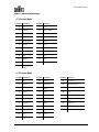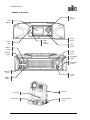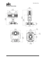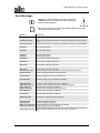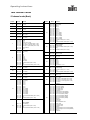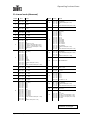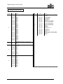
1
User Manual Edition Notes CHAUVET released this edition of the Legend™ 1200E Spot User Manual Rev. 02c in July 2009. Copyright Notice No person, group of persons or entity can reproduce any part of this publication, store it in a retrieval system, or transmit it, in any form or by any means, whether mechanical, electronic, photocopying, recording, or otherwise, without prior written permission of CHAUVET. The Legend™ 1200E Spot User Manual Rev. 02c covers the description, safety precautions, installation, programming and maintenance of the CHAUVET Legend™ 1200E Spot lighting fixture. © Copyright 2009 CHAUVET All rights reserved Printed in the P.R.C. Disclaimers CHAUVET believes that the information contained in this manual is accurate in all respects but CHAUVET does not warrant it. CHAUVET assumes no responsibility for any error or omissions in this document. CHAUVET reserves the right to revise this document and to make changes from time to time in the content hereof without obligation of CHAUVET to notify any person or company of such revision or changes. This does not constitute in any way a commitment by CHAUVET to make such changes. CHAUVET may issue a revision of this manual or a new edition of it to incorporate such changes. Trademarks All products, brand names, or companies mentioned in the document that are not directly or indirectly related with CHAUVET may be trademarks or enabled trademarks of their respective companies. Intended Audience CHAUVET provides The Legend™ 1200E Spot User Manual Rev. 02c with each Legend™ 1200E Spot fixture. Any person in charge of installing, operating and/or maintaining the Legend™ 1200E Spot fixture should read this manual in its entirety before installing, operating or maintaining the fixture. CHAUVET Publications Hot Line Document Revision Fixture at a Glance Legend™ 1200E Spot User Manual If you have any comments about the accuracy of this document or general suggestions regarding how we can improve it, please call us at (800) 762-1084 (US callers) or +1-954-929-1115 (international callers), ext. 43. The latest versions of all CHAUVET manuals are available at CHAUVET’s web site (www.chauvetlighting.com). The Legend™ 1200E Spot User Manual Rev. 02c supersedes all previous versions. Please discard all older versions of this manual. Use on Dimmer Auto Programs Outdoor Use Autoswitching Power Supply Sound Activated Replaceable Fuse DMX User Serviceable Master/Slave CMY Color Mixing I 8/13/2009 10:57 AM Table of Contents 1. Before You Begin ...................................................................................................................................... 1 WHAT IS INCLUDED..................................................................................................................................................................................... 1 UNPACKING INSTRUCTIONS ......................................................................................................................................................................... 1 TEXT CONVENTIONS ................................................................................................................................................................................... 1 ICONS ....................................................................................................................................................................................................... 2 SAFETY INSTRUCTIONS ............................................................................................................................................................................... 2 2. Introduction ............................................................................................................................................... 3 FEATURES ................................................................................................................................................................................................. 3 Additional Features ................................................................................................................................................... 3 DESCRIPTION............................................................................................................................................................................................. 4 23 DMX Channel Mode 1 .......................................................................................................................................... 4 31 DMX Channel Mode 2 .......................................................................................................................................... 4 DMX CHANNEL SUMMARY .......................................................................................................................................................................... 5 PRODUCT OVERVIEW ................................................................................................................................................................................. 6 PRODUCT DIMENSIONS ............................................................................................................................................................................... 7 3. Setup .......................................................................................................................................................... 8 AC POWER ............................................................................................................................................................................................... 8 FUSE REPLACEMENT .................................................................................................................................................................................. 8 FIXTURE LINKING ....................................................................................................................................................................................... 8 Data Cabling ............................................................................................................................................................. 9 DMX Data Cable ....................................................................................................................................................... 9 DMX Cable Connectors ............................................................................................................................................ 9 3-Pin to 5-Pin Conversion Chart .............................................................................................................................. 10 DMX Data Connection ............................................................................................................................................ 10 MOUNTING .............................................................................................................................................................................................. 11 Orientation .............................................................................................................................................................. 11 Rigging ................................................................................................................................................................... 11 Orientation(bracket installation) ............................................................................................................................... 12 Lamp ...................................................................................................................................................................... 13 Lamp Installation ..................................................................................................................................................... 14 Maximizing the life of your lamp .............................................................................................................................. 14 Replacing Gobos .................................................................................................................................................... 15 4. Operating Instructions.............................................................................................................................16 NAVIGATING THE CONTROL PANEL ............................................................................................................................................................ 16 MENU MAP .............................................................................................................................................................................................. 17 OPERATION ............................................................................................................................................................................................. 18 Home Screen .......................................................................................................................................................... 18 DMX Operation ....................................................................................................................................................... 18 Resetting the Fixture ............................................................................................................................................... 18 Factory Default Reset ............................................................................................................................................. 18 Lamp Dousing......................................................................................................................................................... 19 Fixture Maintenance ............................................................................................................................................... 19 Lamp Settings ......................................................................................................................................................... 19 MENU MAP (CONT.) ................................................................................................................................................................................. 20 Home position Adjustment ...................................................................................................................................... 20 ERROR MESSAGES .................................................................................................................................................................................. 21 DMX CHANNEL VALUES ........................................................................................................................................................................... 22 23 channel mode (Basic) ........................................................................................................................................ 22 31 channel mode (Basic) ........................................................................................................................................ 23 GOBO WHEEL LAYOUT .............................................................................................................................................................................. 25 COLOR WHEEL LAYOUT ............................................................................................................................................................................ 25 5. Technical Information ..............................................................................................................................26 GENERAL MAINTENANCE .......................................................................................................................................................................... 26 AIR FILTER CLEANING .............................................................................................................................................................................. 27 RETURNS PROCEDURE ............................................................................................................................................................................. 28 CLAIMS ................................................................................................................................................................................................... 28 CONTACT US ........................................................................................................................................................................................... 28 TECHNICAL SPECIFICATIONS ..................................................................................................................................................................... 29 6. Appendix...................................................................................................................................................31 Legend™ 1200E Spot User Manual I 8/13/2009 10:57 AM Table of Contents DMX PRIMER .......................................................................................................................................................................................... 31 Starting Address ..................................................................................................................................................... 31 Personalities ........................................................................................................................................................... 31 Assigning Addresses .............................................................................................................................................. 31 DMX Fixture Connection ......................................................................................................................................... 31 Legend™ 1200E Spot User Manual II 8/13/2009 10:57 AM Before you Begin 1. Before You Begin What is Included 1 x Legend™ 1200E Spot 2 x Omega Brackets with hanging trigger clamps 1 x Warranty Card 1 x User Manual Hanging Trigger clamp Omega Bracket Unpacking Instructions This product ships in a flight case. Immediately upon receiving the fixture, carefully examine the flight case; check the contents to ensure that all parts are present, and have been received in good condition. If any parts appear damaged from shipping or the carton itself shows signs of mishandling, notify the shipper immediately and retain the packing material for inspection. Save all packing materials because, in the event that you have to return the fixture to the factory, you may return it in its original factory flight case. . Text Conventions CHAUVET manuals use the following text conventions, whether within the regular text or inside tables. MEANING CONVENTION 1~512 A range of values 50/60 A set of mutually exclusive values in the text [10] A DIP switch to be configured A key to be pressed on the fixture’s control panel <SET> Settings A menu option that can be selected but not modified MENU > Settings A sequence of menu options to be followed [1~10] A range of menu values of which one can be selected Yes/No A set of mutually exclusive menu options to choose ON Legend™ 1200E Spot User Manual A value to be entered or selected 1 8/13/2009 10:57 AM Introduction Icons CHAUVET manuals use the following icons to indicate information that requires special attention on the part of the user. MEANING ICONS This paragraph contains critical installation, configuration or operation information. Failure to comply with this information may render the fixture partially or completely inoperative, cause damage to the fixture or cause harm to the user. This paragraph contains important installation or configuration information. Failure to comply with this information may prevent the fixture from functioning correctly. This paragraph reminds you of useful, although not critical, information. Safety Instructions Please read the following instructions carefully because they include important safety information about the installation, usage, and maintenance of this product. There are no user serviceable parts inside the unit. Any reference to unit servicing you may find from now on in this User Manual will only apply to properly CHAUVET certified technicians. Do not open the housing or attempt any repairs unless you are one of them. In the event that your unit may require service, please contact CHAUVET at (954) 923-3680. Keep this manual for future consultation. If you sell the fixture to another user, make sure that they also receive this manual. Always make sure that you are connecting the fixture to the proper voltage, as per the specifications in this manual or on the fixture. Always disconnect the fixture from the power source before servicing. This product is for indoor use only! To prevent risk of fire or shock, do not expose fixture to rain or moisture. Make sure there are no flammable materials close to the fixture while operating. Always secure the fixture to a fastening device using a safety chain. Maximum ambient temperature (Ta) is 104° F (40° C). Do not operate the fixture at a higher temperature. In the event of a serious operating problem, stop using the fixture immediately! Never connect this fixture to a dimmer pack. Make sure the power cord is not crimped or damaged. Never disconnect the power cord by pulling or tugging on the cord. Avoid direct eye exposure to the light source while it is on. Please refer to all applicable local codes and regulations for proper installation of this fixture. Legend™ 1200E Spot User Manual 2 8/13/2009 10:57 AM Introduction 2. Introduction Features . . . . . . . . . . . . . . . . . 23 or 31-channel USITT DMX512-A moving yoke Pan: 540⁰ in 2.8 sec/tilt: 270⁰ in 1.6 sec Color wheel 7 colors + white Red, pink, green, magenta, orange, UV, and blue Split/linear colors Rainbow color spin at variable speeds Indexed, rotating gobo wheel with gobo shake 6 glass, slot-n-lock gobos + open 2 Multicolor, 4 B/W Gobo wheel spin at variable speeds 16-bit gobo rotation Indexed, rotating gobo wheel with gobo shake 6 glass, slot-n-lock gobos + open 1 Multicolor, 5 B/W Gobo wheel spin at variable speeds 16-bit gobo rotation Variable frost Variable CTC filter (3200 K) CMY color mixing system with vector speed adjustments 3-facet, 5-facet, 3D and infinite prism with macros Variable shutter Variable iris Variable focus Variable 16-bit dimming (0~100%) Linear zoom (15⁰~30⁰) Individual reset of pan/tilt, color, gobo, shutter, prism, focus Move-in-black for pan/tilt, color, gobo Remote fixture reset, lamp on/off and vector control speed adjustments Built-in movement macros with range adjustments Built-in color macros . . . . . . . . . . 3-pin and 5-pin DMX connections 2 additional free glass gobos User-configurable lamp ignition delay User-configurable maintenance reminder Electronic ballast with power factor correction Electronic power supply Automatic pan & tilt correction Pan & tilt locks Lamp & fixture use timers Power saver mode . . Additional Features Legend™ 1200E Spot User Manual 3 8/13/2009 10:57 AM Introduction Description The Legend™ 1200E Spot is a moving yoke fixture with a 1200 W short arc discharge lamp. It contains an LCD control panel (display) through which all of the settings can be set/modified. An electronic ballast and power supply provide power to the lamp and electronics of the fixture. This fixture operates at 200~240 VAC, 50/60 Hz. There is no internal power selection switch/terminal. It uses an autoswitching power supply and electronic ballast with power factor correction. 23 DMX Channel Mode 1 The DMX 23 channel mode (Basic) provides 16-bit resolution for the Pan/Tilt functions, and 8-bit resolution for the gobos and prism/effect wheels. 31 DMX Channel Mode 2 The DMX 31 channel mode (Advanced) provides 16-bit resolution for the Pan/Tilt functions, and 16-bit resolution for the gobos and prism/effect wheels, and dimmer. This also includes additional channels for pan/tilt movement macros, CMY/CTO Speed, and color macros & presets Legend™ 1200E Spot User Manual 4 8/13/2009 10:57 AM Introduction DMX Channel Summary 23 Channel Mode CHANNEL ATTRIBUTE CHANNEL ATTRIBUTE 1 Pan 13 Gobo 1 2 Pan fine 14 Gobo 1 rotation 3 Tilt 15 Gobo 2 4 Tilt fine 16 Gobo 2 rotation 5 Pan/tilt speed 17 Focus 6 Dimmer 18 Zoom 7 Shutter 19 Effect/prism 8 Color 20 Effect/prism rotation 9 Cyan 21 Iris 10 Magenta 22 Frost 11 Yellow 23 Function 12 3200 K (CTO) Filter 31 Channel Mode CHANNEL ATTRIBUTE CHANNEL ATTRIBUTE CHANNEL ATTRIBUTE 1 Pan 12 Yellow 23 Effect/prism 2 Pan fine 13 3200K (CTO) 24 Effect/prism rotation 3 Tilt 14 CMY/CTO Filter Speed 25 Iris 4 Tilt fine 15 Gobo 1 26 Frost 5 Pan/tilt speed 16 Gobo 1 rotation 27 Pan/tilt Movement macro 6 Dimmer 17 Gobo 1 rotation fine 28 Pan/tilt Movement macro range 7 Dimmer fine 18 Gobo 2 29 Preset Color 8 Shutter 19 Gobo 2 rotation 30 Color macro (CMY) 9 Color 20 Gobo 2 rotation fine 31 Function 10 Cyan 21 Focus 11 Magenta 22 Zoom Legend™ 1200E Spot User Manual 5 8/13/2009 10:57 AM Introduction Product Overview Jog Wheel LCD Display Enter button DMX LED indicator Power LED indicator Menu button DMX in (3-pin) Power button DMX out (3-pin) Fuseholder (Main) Fuseholder (Lamp) DMX out (5-pin) Power input DMX in (5-pin) Tilt lock Pan lock Control panel Legend™ 1200E Spot User Manual Carrying handle (1 of 2) 6 8/13/2009 10:57 AM Introduction Product Dimensions Legend™ 1200E Spot User Manual 7 8/13/2009 10:57 AM Setup 3. Setup AC Power This fixture has an auto-switching power supply that can work with an input voltage range of 200~240 VAC, 50/60 Hz. Always connect the fixture to a protected circuit with an appropriate electrical ground to avoid the risk of electrocution or fire. To determine the power requirements for a particular fixture, see the label affixed to the back plate of the fixture or refer to the fixture’s specifications chart. A fixture’s listed current rating indicates its average current draw under normal conditions. Never connect the fixture to a rheostat (variable resistor) or dimmer circuit, even if the rheostat or dimmer channel serves only as a 0 to 100% switch. Fuse Replacement 1. With a Phillips #2 screwdriver, unscrew the fuse holder from its housing. 2. Remove the damaged fuse from its holder and replace with exact same type and rating fuse. 3. Screw the fuse holder back in its place and reconnect power. The fuse is located inside this compartment. FUSE Disconnect the power cord before replacing the fuse and always replace it with a fuse of the same type and rating. Fixture Linking If using multiple DMX compatible fixtures, it is possible to control them individually with a single DMX controller or to run them synchronized in a master/slave operating mode. DMX compatible fixtures use a serial data link between them. The connection between fixtures follows a daisy chain pattern (the DMX output of a fixture connects to the DMX input of the next fixture, and so on). When using a DMX controller, the combined number of channels required by all the fixtures on the serial data link determines the number of fixtures the DMX controller can support. To comply with the EIA-485 standard, which is the base for the DMX standard, do not connect more than 32 fixtures without using a DMX optically-isolated splitter. Doing otherwise may result in deterioration of the digital DMX signal. Legend™ 1200E Spot User Manual 8 8/13/2009 10:57 AM Setup Data Cabling You must use DMX compliant data cables to link two or more DMX compatible fixtures together. You may purchase CHAUVET certified DMX cables directly from a dealer/distributor or construct your own cable. USITT recommends limiting the total length of the DMX cable (from the first fixture/controller to the last fixture) to 300 ~ 455 m (985 ~ 1,500 ft). If you choose to create your own cable, make sure to use data-grade cables that can carry a high frequency signal and are less prone to electromagnetic interference. Use a Belden© 9841 or equivalent cable, which meets the specifications for EIA RS-485 applications. Do not use standard microphone cables for DMX applications because they cannot transmit DMX data reliably over long distances. DMX Data Cable The data cable must have the following characteristics: Type: shielded, 2-conductor twisted pair Maximum capacitance between conductors: 30 pF/ft Maximum capacitance between conductor and shield: DMX Cable Connectors 55 pF/ft Maximum resistance: 20 ohms/1000 ft Nominal impedance: 100 ~ 140 ohms Each DMX cable must have a male, 3 or 5-pin XLR connector on one end and a female, 3 or 5-pin XLR connector on the other end. DMX Connector Configuration To DMX Input (Female) To DMX Output (Male) 120 ohm ¼ W resistor between pin 2 (DMX -) and pin 3 (DMX +) on the output of the last fixture. Common 1 3 2 DMX + DMX - 1 3 2 To avoid signal transmission problems and interference, it is always advisable to connect a DMX signal terminator, as seen below. 1 3 2 120 ohm, ¼ W resistor between pin 2 (DMX -) and pin 3 (DMX +) on the output of the last fixture. Test all DMX cables with an ohmmeter to verify their correct polarity and to make sure that there are no short-circuits between any of the pins, or between any pin and ground. If the Common wire touched the chassis ground, a ground loop could form, which may cause the fixture to perform erratically. Legend™ 1200E Spot User Manual 9 8/13/2009 10:57 AM Setup 3-Pin to 5-Pin Conversion Chart It may be necessary to use a 3-pin to 5-pin adapter. Please see the chart below for further explanation. 3-PIN TO 5-PIN CONVERSION CHART Conductor 3-Pin Female (Output) 5-Pin Male (Input) Ground/Shield Pin 1 Pin 1 Data ( - ) signal Pin 2 Pin 2 Data ( + ) signal Pin 3 Pin 3 Not used Pin 4 Not used Pin 5 You may use the 3-pin input with the 5-pin output. You may also use 5-pin input with the 3-pin output. However, you may NOT use both the 3-pin and the 5-pin outputs simultaneously. DMX Data Connection The fixture uses the DMX data connection for its DMX 23 & 31 Channel modes. See the “Introduction” chapter for a description of the two DMX Channel modes and the “Operation Instructions” chapter to learn how to configure the fixture appropriately for this mode. 1. Connect the male connector of the first DMX cable to the DMX Output connector (female) of the DMX controller. 2. Connect the, female connector of the first DMX cable coming from the controller to the DMX Input connector (male) of the first fixture. 3. Connect the male connector of the second DMX cable to the DMX Output connector (female) of the first fixture. 4. Connect the female connector of the second DMX cable coming from the first fixture to the DMX Input connector of the second fixture. 5. Continue linking the other fixtures in the same way. Universal DMX Controller rd DMX Data Connection Diagram 3 DMX Cable Next fixture CHAUVET Certified DMX Data Cables Legend™ 1200E Spot User Manual 1st DMX Cable 2nd DMX Cable 2nd fixtures DMX Output 1st fixture DMX Output DMX Input Order Code Description DMX1.5 DMX Cable 1.5 m/4.9 ft DMX4.5 DMX Cable 4.5 m/14.8 ft DMX10 DMX Cable 10 m/32.8 ft 10 DMX Input 8/13/2009 10:57 AM Setup Mounting Orientation Only mount this fixture in a horizontal position, either hanging or standing, as indicated in the diagram below. Be sure that there is adequate room for ventilation and for the pan/tilt motion of the fixture. Doing otherwise may void this fixture’s warranty and cause damage to the fixture. Standing position Hanging position Standing position Rigging The Legend™ 1200E Spot ships in a flight case specially designed to fit the fixture. There are two omega brackets with clamps included in the flight case. When selecting an installation location, consider ease of access to the fixture for operation, lamp replacement, programming adjustment(s) and routine maintenance. Never mount the fixture in places where rain, high humidity, extreme temperature changes or restricted ventilation may affect it. Make sure that the location where you are mounting the fixture can support its weight. Please see the “Technical Specifications” section of this manual for the weight requirement of this fixture. Safety Omega brackets with clamps Legend™ 1200E Spot User Manual 11 8/13/2009 10:57 AM Setup Orientation (bracket installation) The brackets in this fixture may be mounted on either side of the mounting plate, thus allowing for a 90° rotation of the fixture. Please see the diagram below for further explanation. Location 1 Control Panel Location 2 Control Panel Legend™ 1200E Spot User Manual 12 8/13/2009 10:57 AM Setup Lamp When replacing the lamp, please wait at least 15 minutes after powering down to allow the unit to cool! More time may be necessary. Always disconnect from main power prior to lamp replacement. Do not touch the envelope (glass area) of the bulb with bare hands. If this happens, clean the lamp with isopropyl alcohol and wipe it with a lint free cloth before installation. You should use cotton or latex gloves to avoid from touching the lamp envelope with your bare hands. Lamp cover ¼ - turn screws Lamp alignment screws Lamp Legend™ 1200E Spot User Manual 13 8/13/2009 10:57 AM Setup The lamp in this fixture is not common and requires specific installation procedures. Please see the diagram, along with the set of instructions, below for further explanation. Lamp Installation 1. Disconnect power from the fixture and allow it to cool. 2. Lock the head of the fixture. 3. Unscrew the two ¼ - turn screws (X & Y) to open the rear lamp cover (this will remain attached via a rotating arm). 4. If you are replacing a lamp, you will need to remove the old lamp from the fixture. Using your thumb and forefinger, grasp the ceramic base of the lamp and turn it 45° counterclockwise to the unlocked position. Then, pull it straight out of the fixture, being careful not to touch the sides of the reflector or housing. 5. The lamp base has two metal contacts, one narrow and one wide, which fit into the corresponding narrow and wide slots in the lamp holder. Align the new lamp with these slots in the lamp holder, and slide the lamp into the fixture until the contacts are fully inserted. Using your thumb and forefinger, grasp the ceramic base of the lamp and turn it 45° clockwise to the locked position. 6. Close the rear lamp cover, and tighten the two ¼ - turn screws (X & Y). 7. After installing a new lamp, reset the lamp hour counter (see “Menu Map” for the menu option to perform this reset). You should use cotton or latex gloves to avoid from touching the lamp envelope with your bare hands. Locked Maximizing the Life of Your Lamp Legend™ 1200E Spot User Manual Unlocked To ensure the longest and most efficient use of the lamp, always wait between 10~15 min before re-applying power after a shutdown. Failure to do so could result in premature aging of the lamp and failure of the electronics that drive it. Never turn off the power to the unit while the lamp is striking. Always wait 15 min after powering on the fixture before powering it down. Turning off the lamp during striking may permanently damage the lamp. 14 8/13/2009 10:57 AM L Setup Replacing Gobos This fixture comes with slot-n-lock gobo wheels for easy gobo replacement/installation. Please see the diagram, along with the set of instructions, below for further explanation. 1. Unscrew the four ¼- turn screws (S2) to detach the front cover. 2. Remove the slot-n-lock gobo single assembly. Using your thumb and forefinger, grasp the slot-n-lock gobo assembly and remove it from the gobo wheel. 3. Using a small prying tool, remove the gobo tension ring and remove it from the gobo aperture. Push the gobo with your finger from the back side following the same direction that the tension ring was removed. S2 slot-n-lock gobo single assembly You should use cotton or latex gloves to avoid from touching the gobos with your bare hands. The tension ring could pop out abruptly and fall inside the fixture. Use caution when removing it and, if necessary, use both hands. Replace the slot-n-lock prism(s) on the prism/effect wheel using the same method as the rotating gobo wheel. Legend™ 1200E Spot User Manual 15 8/13/2009 10:57 AM Operating Instructions 4. Operating Instructions Navigating the Control Panel Access the control panel functions using the two panel buttons located directly to the right of the LCD Display. Please see the chart, diagram, and set of instructions, below for further explanation. Button Function <MENU> Used to access the menu or to return to a previous menu option <ENTER> Used to select and store the current menu option within a menu <JOG WHEEL> Used to scroll through the menu options, and to modify the value of a setting Jog Wheel Menu button Enter button The Control Panel LCD Display shows the menu items you select from the “menu map” section. When a menu function is selected, the display will show the first available option for the selected menu function. To select a menu item, press <ENTER>. Press <MENU> repeatedly until the home screen is displayed. Press <MENU> one more time. This is the top of the menu map. Use the <JOG WHEEL> to navigate the menu map and menu options. Press <ENTER> to access the menu function currently displayed or to enable a menu option. To return to the previous option or menu without changing the value, press <MENU>. Legend™ 1200E Spot User Manual 16 8/13/2009 10:57 AM Operating Instructions Menu Map Main Function Sub Function Selection DMX Address DMX Functions 1~512 Mode 1 (23) DMX Channel Mode Mode 2 (31) View DMX Value Pan Inverse Tilt Inverse Bl.o. P/T Moving Fixture Settings Bl.o. Color Change Bl.o. Gobo Change Auto Focus On/Off State/Power On Off Via DMX On if DMX On Off if DMX Off Yes/No Yes/No Yes/No Yes/No Yes/No Yes/No On/Off On/Off Yes/No Yes/No Yes/No Lamp Settings High Cooling Mode Auto Ignition Delay 0s~255s Low Power Delay 0s~255s Display Inverse Yes/No Back Light Auto Off Yes/No Display Settings Back Light Intensity 1~10 °C Temperature Unit °F Auto Test Fixture Test Manual Test Fixture use time Fixture Information Reset Function Special Functions Exit Lamp On Time Reset Time Firmware Version Pan & Tilt Yes/No Color Yes/No Gobo & Iris Shutter & Dimmer Focus & Zoom Prism & Frost All Fixture Maintenance Yes/No Yes/No Yes/No Yes/No Yes/No Interval Remain Time Factory Settings Yes/No Legend™ 1200E Spot User Manual Instruction DMX starting address assignment Operating mode: Basic Operating mode: Advanced View the DMX input values (only from the starting address through the last channel of the mode (23/31) Inverts the Pan operation from 540 ~ 0 Inverts the Tilt operation from 270 ~ 0 Enables Blackout while pan/tilt moving Enables Blackout while Color moving Enables Blackout while Gobo moving Enables auto focus while zooming narrow/wide Manual Control of the lamp state Automatically strikes the lamp upon powering on the fixture Allows remote Lamp Off commands to be received via DMX Strikes the lamp if DMX is present Turns off the lamp if DMX is not present Maintains the fans at highest speed, regardless of lamp temperature Maintains the lowest (most silent), possible fan speed, according to the lamp temperature Delays striking the lamp to allow for lower inrush currents Sets the time activating delay between the shutter/dimmer closing and the lamp power reduction. The maximum delay is 255 seconds Inverts the display graphics 180° Turns off the backlight after several seconds of being idle Sets the backlight intensity from dim to bright Displays the temperature in Celsius Displays the temperature in Fahrenheit Runs the fixture, testing each function in series Manually controls each function of the fixture directly from the control panel without a DMX controller; used for testing/troubleshooting purposes only Displays the amount of time the fixture has been operating Exits this function Resets the lamp time (used when replacing the lamp in the fixture) Displays the firmware version of each software chip Resets the pan & tilt, independent of the other motors Resets the color wheel, CMY, & 3200 K (CTO) dichroic flags, independent of the other motors Resets the gobo & iris, independent of the other motors Resets the shutter & dimmer, independent of the other motors Resets the focus & zoom, independent of the other motors Resets the prism & frost, independent of the other motors Resets all motors in the fixture simultaneously User can set the custom time for this Warning message Shows the time remaining from the current interval user time Resets all settings to the factory defaults, with the exception of the motor offset settings 17 8/13/2009 10:57 AM Operating Instructions Operation Home Screen By default, when the fixture is operating under normal circumstances, the display screen will list critical information. Please see the diagram, along with the set of instructions, below for further explanation. Error Alert Icon Current DMX Address Internal Fixture Temperature DMX Operating Mode DMX Operation This is the explanation of how to setup the fixture to operate with a DMX controller. Please see the set of instructions below for further explanation. 1. 2. 3. 4. Resetting the Fixture If there is an operation error in this fixture, a fixture reset will often correct such a problem. Please see the set of instructions below for further explanation. 1. 2. 3. 4. Factory Default Reset Press <MENU>. Select: DMX Functions>DMX Address>. Rotating the <JOG WHEEL>, select a DMX address. Press <ENTER>. Press <MENU>. Select: Fixture Test. Rotating the <JOG WHEEL>, select Manual Test or Auto Test. Press <ENTER>. You may reset all settings to the factory default from the LCD display. Please see the set of instructions below for further explanation. 1. 2. 3. 4. Press <MENU>. Select: Special Function<Factory Settings. Rotating the <JOG WHEEL>, select Yes or No. Press <ENTER>. Please be aware that this action will cause all settings to revert to the state they were at when the fixture shipped from the manufacturer. This will not affect the home position adjustments. Legend™ 1200E Spot User Manual 18 8/13/2009 10:57 AM Operating Instructions Lamp Dousing Due to the extreme heat produced by the lamp, closing the shutters/dimmers for an extended period will cause a build-up of heat. However, a function in the fixture will automatically reduce the power to the lamp when the shutters/dimmers are closed. This will reduce the heat, and prolong the life of the fixture. There is a time delay for which this feature will activate. Please see the set of instructions below for further explanation. 1. 2. 3. 4. Fixture Maintenance This fixture has a user-selectable period for routine maintenance. This setting will cause an error alert icon to appear on the home screen. Please see the set of instructions below for further explanation. 1. 2. 3. 4. Lamp Settings Press <MENU>. Select: Lamp Settings>Low Power Delay. Rotating the <JOG WHEEL>, select 0~255s. This is the actual time delay. Press <ENTER>. Press <MENU>. Select: Special Function>Fixture Maintenance>Interval. Rotating the <JOG WHEEL>, select the actual time delay. Press <ENTER>. You may modify several parameters for the lamp’s on/off state as well as the lamp cooling. Please see the set of instructions below for further explanation. Select: Lamp Settings>On/Off Manually control the current state of the lamp. Select: Lamp Settings>State Power On When activated, the lamp will strike immediately upon the fixture receiving power, provided that there is no ignition delay applied. Select: Lamp Settings>Off via DMX Allows remote Lamp Off through DMX. Select: Lamp Settings>On if DMX On When activated, the fixture will attempt to strike the lamp when DMX is received by the fixture. Select: Lamp Settings> Off if DMX Off When activated, the fixture will attempt to turn off the lamp when DMX is lost by the fixture. Select: Lamp Settings> Cooling Mode> High Manually set fans to maximum cooling level. Select: Lamp Settings> Cooling Mode> Auto Manually set fans to automatic cooling. Select: Lamp Settings> Ignition Delay This will cause an ignition delay upon power up the fixture, if the State Power On option is activated. Legend™ 1200E Spot User Manual 19 8/13/2009 10:57 AM Operating Instructions Menu Map (Cont.) Home position Adjustment The “home position” is the location the fixture finds during the reset (home) process. This is commonly known as electronic adjustment. This is a hidden menu in the fixture. If the home position of one of the motors becomes misaligned, you can use this menu to realign/offset the function. Please see the chart, along with the set of instructions, below for further explanation. 1. Press <MENU> repeatedly until you reach the main menu. This includes any menu option in the leftmost column of the “Menu Map” section of this manual. 2. Press and hold <ENTER> for 5s until the screen reads Offset Menu. 3. Scroll to the desired attribute using the <JOG WHEEL>. 4. Press <ENTER>. 5. Rotate the <JOG WHEEL> to adjust the home position of the selected attribute. 6. Once the position has been selected, press <ENTER>. 7. Press <MENU> repeatedly to back out of the function and return to the home screen. The “home position” for each motor will change as the position is selected. Legend™ 1200E Spot User Manual MAIN FUNCTION INSTRUCTION Pan Tilt Shutter Color Cyan Magenta Yellow 3200 K Filter Gobo 1 R-Gobo 1 Gobo 2 R-Gobo 2 Iris Prism R-Prism Frost Focus Zoom Pan motor offset Tilt motor offset Shutter motor offset Color motor offset Cyan dichroic flag motor offset Magenta dichroic flag motor offset Yellow dichroic flag motor offset 3200 K Filter dichroic flag motor offset Gobo wheel 1 motor offset Gobo wheel 1 rotation motor offset Gobo wheel 2 motor offset Gobo wheel 2 rotation motor offset Iris motor offset Prism/effect wheel motor offset Prism rotation motor offset Frost dichroic flag motor offset Focus motor offset Zoom motor offset 20 8/13/2009 10:57 AM Operating Instructions Error Messages When the error alert icon appears on the home screen, press <ENTER> to view the error information. Please see the chart below for further explanation. Once an error has been resolved, you may perform a fixture reset to remove the message from the home screen. MESSAGE DESCRIPTION Lamp Startup Fail Failed to strike the lamp after 1 minute (1 attempt). The lamp has reached a temperature between 105° C and 109° C; the lamp will operate at half power while at these temperatures to attempt to bring the temperature to normal levels The lamp has reached 110° C or higher, and has been turned off as a safety precaution The user-selected time for maintenance has been reached Fan 1 has malfunctioned Fan 2 has malfunctioned Fan 3 has malfunctioned Fan 4 has malfunctioned Fan 5 has malfunctioned Fan 6 has malfunctioned Communication malfunction with CPU-B Communication malfunction with CPU-C Communication malfunction with CPU-D Communication malfunction with CPU-E Communication malfunction with CPU-F Communication malfunction with CPU-G Lamp Hot Protection Lamp Hot Power Off Maintenance Fixture Fan1 Error Fan2 Error Fan3 Error Fan4 Error Fan5 Error Fan6 Error CPU-B Error CPU-C Error CPU-D Error CPU-E Error CPU-F Error CPU-G Error CPU-H Error Pan Home Sensor Error Pan Encode Error Tilt Home Sensor Error Tilt Encode Error Color 1 Reset Fail Cyan Reset Fail Magenta Reset Fail Yellow Reset Fail 3200K Filter Reset Fail Gobo 1 Reset Fail R-Gobo 1 Reset Fail Gobo 2 Reset Fail R-Gobo Reset Fail Iris Reset Fail Effect Reset Fail R-Effect Reset Fail Frost Reset Fail Focus Reset Fail Zoom Reset Fail Memory Initial Reset Fail Temperature Sense Fail Communication malfunction with CPU-H The pan has failed to reset/home properly; check sensor, magnet, or pan lock The pan encoding/optical sensor has malfunctioned The tilt has failed to reset/home properly; check sensor, magnet, or tilt lock The tilt encoding/optical sensor has malfunctioned The color wheel has failed to reset/home The dichroic shutter for cyan has failed to reset/home The dichroic shutter for magenta has failed to reset/home The dichroic shutter for yellow has failed to reset/home The dichroic shutter for 3200 K CTO Filter has failed to reset/home The Gobo wheel 1 has failed to reset/home The Gobo wheel 1 rotation has failed to reset/home The Gobo wheel 2 has failed to reset/home The Gobo wheel 2 rotation has failed to reset/home The motorized iris has failed to reset/home The effect/prism wheel has failed to reset/home The effect/prism rotation has failed to reset/home The frost filter has failed to reset/home The focus has failed to reset/home The zoom has failed to reset/home Memory malfunction or miscommunication; chip: 24C256 The temperature sensor is not responding The lamp has been operating for over 700 hours, please consult the lamp manufacturer’s Lamp On Over 700 Hour rating for the lamp. This can be reset in the control panel of the fixture Legend™ 1200E Spot User Manual 21 8/13/2009 10:57 AM Operating Instructions DMX Channel Values 23 channel mode (Basic) CHANNEL VALUE FUNCTION 1 000 255 Pan 0 540 2 000 255 Pan fine 3 000 255 Tilt 0 270 4 000 255 Tilt fine 5 000 255 Pan/tilt Speed Fast slow 6 000 255 Dimmer 0% 100% 000 007 008 015 016 131 132 167 168 203 204 239 240 247 248 255 Shutter Closed Open Shutter (slow fast) Slow open fast closed (slow fast) Slow closed fast open (slow fast) Slow open slow closed (slow fast) Random Strobe Open 000 007 008 015 016 023 024 031 032 039 040 047 048 055 056 063 064 127 128 189 190 193 194 255 Color Open (white) Red Blue Pink Green Yellow Orange UV Purple Split Colors Clockwise rotation (fast slow) Stop Counter-clockwise rotation (slow fast) 000 255 Cyan 0% 100% 10 000 255 Magenta 0% 100% 11 000 255 Yellow 0% 100% 12 000 255 3200 K/CTO Filter 0% 100% 000 009 010 019 020 028 029 038 039 047 048 057 058 067 068 077 078 087 088 097 098 107 108 117 118 127 128 189 190 193 194 255 Gobo 1 Open (white) Gobo 1 Gobo 2 Gobo 3 Gobo 4 Gobo 5 Gobo 6 Gobo 1 shake Gobo 2 shake Gobo 3 shake Gobo 4 shake Gobo 5 shake Gobo 6 shake Counter-clockwise rotation (fast slow) Stop Clockwise rotation (slow fast) 7 8 9 CHANNEL 15 Gobo indexing Counter-clockwise rotation (fast slow) Stop Clockwise rotation (slow fast)) 000 255 Focus Narrow wide 18 000 255 Zoom 15° 30° 000 025 026 050 051 076 077 101 102 127 128 255 Effect/prism Open Effect 1 Effect 2 Effect 3 Effect 4 Effect Macro 1 24 000 127 Gobo indexing 128 189 Clockwise rotation (fast slow) 190 193 Stop 194 255 Counter-clockwise rotation (slow fast) 21 Iris 000 255 100% 0% 22 000 179 180 201 202 223 224 245 246 255 Frost 0% 100% Slow open fast closed (slow fast) Slow closed fast open (slow fast) Slow closed slow open (slow fast) Frost effect 000 009 010 019 020 029 030 039 040 049 050 069 070 079 080 089 090 099 100 109 110 119 120 129 130 139 140 149 150 159 160 169 170 179 180 189 190 199 200 209 210 219 220 229 230 239 240 255 Function No function Auto focus (enable) Auto focus (disable) Fan speed (auto) Fan speed (high) No function Pan/tilt move-in-black (enable) Pan/tilt move-in-black (disable) Color move-in-black (enable) Color move-in-black (disable) Gobo move-in-black (enable) Gobo move-in-black (disable) Lamp On Pan/tilt reset Color reset Gobo1/Gobo2/Iris reset Shutter reset Focus/zoom reset Frost/effect reset Reset all Pan/tilt/color/gobo move-in-black (enable) Pan/tilt/color/gobo move-in-black (disable) Lamp off No function 23 Stop Counter-clockwise rotation (slow fast) Legend™ 1200E Spot User Manual 000 127 128 189 190 193 194 255 Effect/prism rotation 000 127 Gobo indexing 128 189 Clockwise rotation (fast slow) 190 193 194 255 Gobo 2 Open (white) Gobo 7 Gobo 8 Gobo 9 Gobo 10 Gobo 11 Gobo 12 Gobo 7 shake Gobo 8 shake Gobo 9 shake Gobo 10 shake Gobo 11 shake Gobo 12 shake Clockwise rotation (fast slow) Stop Counter-clockwise rotation (slow fast) 17 19 Gobo 1 rotation 14 000 009 010 019 020 028 029 038 039 047 048 057 058 067 068 077 078 087 088 097 098 107 108 117 118 127 128 189 190 193 194 255 FUNCTION Gobo 2 rotation 16 20 13 VALUE 22 8/13/2009 10:57 AM Operating Instructions 31 channel mode (Advanced) CHANNEL VALUE FUNCTION 1 000 255 Pan 0 540 2 000 255 Pan fine 3 000 255 Tilt 0 270 4 000 255 Tilt fine 5 000 255 Pan/tilt Speed Fast slow 6 000 255 Dimmer 0% 100% 7 000 255 Dimmer fine 000 007 008 015 016 131 132 167 168 203 204 239 240 247 248 255 Shutter Closed Open Shutter (slow fast) Slow open fast closed (slow fast) Slow closed fast open (slow fast) Slow open slow closed (slow fast) Random Strobe Open 000 007 008 015 016 023 024 031 032 039 040 047 048 055 056 063 064 127 128 189 190 193 194 255 Color Open (white) Red Blue Pink Green Yellow Orange UV Purple Split Colors Clockwise rotation (fast slow) Stop Counter-clockwise rotation (slow fast) 10 000 255 11 CHANNEL 9 FUNCTION 000 127 128 189 190 193 194 255 Gobo 1 rotation Gobo indexing Clockwise rotation (fast slow) Stop Counter-clockwise rotation (slow fast) 17 000 255 Gobo 1 rotation fine 18 000 009 010 019 020 028 029 038 039 047 048 057 058 067 068 077 078 087 088 097 098 107 108 117 118 127 128 189 190 193 194 255 Gobo 2 Open (white) Gobo 7 Gobo 8 Gobo 9 Gobo 10 Gobo 11 Gobo 12 Gobo 7 shake Gobo 8 shake Gobo 9 shake Gobo 10 shake Gobo 11 shake Gobo 12 shake Clockwise rotation (fast slow) Stop Counter-clockwise rotation (slow fast) 000 127 128 189 190 193 194 255 Gobo 2 rotation Gobo indexing Counter-clockwise rotation (fast slow) Stop Clockwise rotation (slow fast)) 16 8 VALUE 19 20 000 255 Gobo 2 rotation fine Cyan 0% 100% 21 000 255 Focus Narrow wide 000 255 Magenta 0% 100% 22 000 255 Zoom 15° 30° 12 000 255 Yellow 0% 100% 13 000 255 3200 K (CTO) Filter 0% 100% 14 000 255 CMY/CTO Speed Fast slow 000 025 026 050 051 076 077 101 102 127 128 255 Effect/prism Open Effect 1 Effect 2 Effect 3 Effect 4 Effect Macro 1 24 000 009 010 019 020 028 029 038 039 047 048 057 058 067 068 077 078 087 088 097 098 107 108 117 118 127 128 189 190 193 194 255 Gobo 1 Open (white) Gobo 1 Gobo 2 Gobo 3 Gobo 4 Gobo 5 Gobo 6 Gobo 1 shake Gobo 2 shake Gobo 3 shake Gobo 4 shake Gobo 5 shake Gobo 6 shake Counter-clockwise rotation (fast slow) Stop Clockwise rotation (slow fast) 15 23 Effect/prism rotation 24 000 127 Gobo indexing 128 189 Clockwise rotation (fast slow) 190 193 Stop 194 255 Counter-clockwise rotation (slow fast)) 25 26 Iris 000 255 100% 0% 000 179 180 201 202 223 224 245 246 255 Frost 0% 100% Slow open fast closed (slow fast) Slow closed fast open (slow fast) Slow closed slow open (slow fast) Frost effect Continued on next page… Legend™ 1200E Spot User Manual 23 8/13/2009 10:57 AM Operating Instructions …continued from previous page CHANNEL 27 VALUE 000 007 008 015 016 023 024 031 032 039 040 047 048 055 056 063 064 071 072 079 080 087 088 095 096 103 104 111 112 119 120 127 128 135 136 143 144 151 152 159 160 167 168 175 176 183 184 191 192 199 200 207 208 223 224 231 232 239 240 247 248 255 FUNCTION CHANNEL Pan/tilt Macro (works in conjunction with CH.28) Off Macro 1 Macro 2 Macro 3 Macro 4 Macro 5 Macro 6 Macro 7 Macro 8 Macro 9 Macro 10 Macro 11 Macro 12 Macro 13 Macro 14 Macro 15 Macro 16 Macro 17 Macro 18 Macro 19 Macro 20 Macro 21 Macro 22 Macro 23 Macro 24 Macro 25 Macro 26 Macro 27 Macro 28 Macro 29 Macro 30 Macro 31 000 255 Pan/tilt Macro Range (works in conjunction with CH.27) 0% 100% 29 000 021 022 042 043 063 064 085 086 106 107 127 128 148 149 170 171 191 192 212 213 233 234 255 Preset Color Open (white) Color 1 Color 2 Color 3 Color 4 Color 5 Color 6 Color 7 Color 8 Color 9 Color 10 Color 11 30 000 007 008 028 029 049 050 069 070 090 091 110 111 131 132 152 153 173 174 194 195 215 216 235 236 255 Color Macro Open Macro 1 Macro 2 Macro 3 Macro 4 Macro 5 Macro 6 Macro 7 Macro 8 Macro 9 Macro 10 Macro 11 Macro 12 28 Legend™ 1200E Spot User Manual 24 31 VALUE 000 009 010 019 020 029 030 039 040 049 050 069 070 079 080 089 090 099 100 109 110 119 120 129 130 139 140 149 150 159 160 169 170 179 180 189 190 199 200 209 210 219 220 229 230 239 240 255 FUNCTION Function No function Auto focus (enable) Auto focus (disable) Fan speed (auto) Fan speed (high) No function Pan/tilt move-in-black (enable) Pan/tilt move-in-black (disable) Color move-in-black (enable) Color move-in-black (disable) Gobo move-in-black (enable) Gobo move-in-black (disable) Lamp On Pan/tilt reset Color reset Gobo1/Gobo2/Iris reset Shutter reset Focus/zoom reset Frost/effect reset Reset all Pan/tilt/color/gobo move-in-black (enable) Pan/tilt/color/gobo move-in-black (disable) Lamp off No function 8/13/2009 10:57 AM Operating Instructions Gobo wheel Layout 5 11 12 6 10 4 3 9 1 7 2 8 Color Wheel Layout Legend™ 1200E Spot User Manual 25 8/13/2009 10:57 AM Technical Information 5. Technical Information General Maintenance To maintain optimum performance and minimize wear, the user should clean the fixtures frequently. Usage and environment are contributing factors in determining the cleaning frequency. As a rule, the user should clean the fixtures at least twice a month. Dust build up reduces light output performance and can cause overheating. This can lead to reduced lamp life and increased mechanical wear. For fixtures containing external optical lenses, the user should clean them periodically to optimize light output. Cleaning frequency depends on the environment in which the fixture operates. Damp, smoky or particularly dirty surrounding can cause greater accumulation of dirt on the unit’s optics. Even in the cleanest type of surroundings, the user should clean the external optics at least once every 30 days. CHAUVET recommends cleaning the fixture’s external optics with a soft cloth using normal glass cleaning fluid. There is a recommended process for cleaning the fixture. Please see the set of instructions below for further explanation. Unplug fixture from power. Carefully use a vacuum or air compressor, along with a soft brush, to remove dust collected on external vents and internal components. Ensure the fixture is cool. Clean all external optics and glass surfaces with a mild solution of glass cleaner or isopropyl alcohol, using a soft, lint free cotton cloth or lens tissue. Apply solution directly to the cloth or tissue and drag dirt and grime to the outside of the lens. Gently polish the external glass surfaces until they are free of haze and lint. Always dry the external optics and glass surfaces carefully after cleaning them. Never spin a fan using compressed air/vacuum. Legend™ 1200E Spot User Manual 26 8/13/2009 10:57 AM Technical Information Air Filter Cleaning This fixture contains air filters to reduce dust and debris from building up on the internal components. Please see the diagram below for further explanation. Although there are air filters present in the vents of this fixture, it is still necessary to perform regular maintenance of the internal components, on a regular interval. This includes the cleaning of the lenses and the dichroic filters. Legend™ 1200E Spot User Manual 27 8/13/2009 10:57 AM Technical Information Returns Procedure The user must send the merchandise prepaid. CHAUVET will not issue call tags. The user must clearly label the package with a Return Merchandise Authorization Number (RMA #). CHAUVET will refuse any product returned without an RMA #. Call CHAUVET and request an RMA # before shipping the fixture. Be prepared to provide the model number, serial number and a brief description of the cause for the return. Be sure to pack the fixture properly. Any shipping damage resulting from inadequate packaging is the customer’s responsibility. As a suggestion, the fixture should be returned in the original flight case. CHAUVET reserves the right to use its own discretion to repair or replace returned product(s). Once you are given an RMA #, please include the following information on a piece of paper inside the flight case: Your name Your address Your phone number The RMA # A brief description of the symptoms Claims Contact Us Legend™ 1200E Spot User Manual Damage incurred in shipping is the responsibility of the shipper. Therefore, the customer must report any damage to the carrier upon receipt of merchandise. It is the customer's responsibility to notify and submit claims with the shipper in the event that a fixture appears damaged due to shipping. The customer must make claims for other issues, such as missing components or parts, damage not related to shipping, or concealed damage to CHAUVET within seven (7) days of receiving merchandise. World Wide General Information Chauvet Lighting 3000 North 29th Court Hollywood, FL 33020 voice: (954) 929-1115 fax: (954).929-5560 toll free: (800) 762-1084 Technical Support www.chauvetlighting.com voice: (954) 929-1115 (Press 4) fax: (954) 929-5560 (Attention: Service) World Wide Web www.chauvetlighting.com 28 8/13/2009 10:57 AM Technical Information Technical Specifications WEIGHT & DIMENSIONS (OF FIXTURE) Length ............................................................................................ 21.2 in (539 mm) Width.............................................................................................. 21.5 in (545 mm) Height ............................................................................................ 30.1 in (764 mm) Weight....................................................................................... 82.05 lbs (37.22 kg) For more detailed dimensions, please see the “Product Dimensions” section of this manual. WEIGHT & DIMENSIONS (OF FIXTURE IN FLIGHT CASE) Length ............................................................................................... 25 in (635 mm) Width................................................................................................. 28 in (711 mm) Height ............................................................................................... 35 in (889 mm) Weight..................................................................................... 191.05 lbs (86.22 kg) POWER Auto-ranging electronic power supply (w/PF correction) ....... 200-255 VAC 50/60 Hz Fuse ......................................................................F15 A 250 V 6 x 30 mm fast-blow Power Consumption @ 200 V 50 Hz ...................................... 1,980 W (8.25 A) max Inrush Power @ 200 V 50 Hz ........................................................................... 3.6 A Power Factor @ 200 V 50 Hz .............................................................................0.93 Power Consumption @ 208 V 60 Hz ...................................... 1,641 W (7.89 A) max Inrush Power @ 208 V 60 Hz ........................................................................... 3.4 A Power Factor @ 208 V 60 Hz .............................................................................0.93 Power Consumption @ 220 V 50 Hz ...................................... 1,646 W (7.48 A) max Inrush Power @ 220 V 50 Hz ........................................................................... 3.1 A Power Factor @ 220 V 50 Hz .............................................................................0.93 Power Consumption @ 230 V 50 Hz ...................................... 1,645 W (7.15 A) max Inrush Power @ 230 V 50 Hz ........................................................................... 3.3 A Power Factor @ 230 V 50 Hz .............................................................................0.92 Power Consumption @ 240 V 50 Hz ...................................... 1,654 W (6.89 A) max Inrush Power @ 240 V 50 Hz ........................................................................... 3.3 A Power Factor @ 240 V 50 Hz .............................................................................0.91 LIGHT SOURCE Type ...............................................................................1200 W short arc discharge Approved lamp ......................... Philips® MSR1200SA/SE FastFit™ 6300 K, 750 hrs Socket ......................................................................................................... PGJX50 PHOTO OPTIC Zoom at minimum Luminance @ 2 m .................................................................................... 19,400 lux Beam Angle (zoom)............................................................................................. 30° Zoom at maximum Luminance @ 2 m .................................................................................... 84,000 lux Beam Angle (zoom)............................................................................................. 15° Measurement lamp used: Philips® MSR1200SA/SE FastFit™ 6300 K 750 hrs Measurement conditions: 240 V, 60 Hz, no effects applied CONTRUCTION Ingress Protection ............................................................................................. IP20 Housing............................................. Self extinguishing ABS (meets CSA approval) Color ................................................................................................................ Black RANGE Pan ................................................................................................................... 540° Tilt ..................................................................................................................... 270° INSTALLATION Mounting points .............................................................. two ¼-turn omega brackets Orientation ............................................... vertically pointing straight down (hanging) .....................................................................................................straight up (sitting) Minimum distance form illuminated surface ......................................... 100 in (2.5 m) Minimum distance form combustible materials ........................................ 8 in (0.2 m) GOBOS Outside diameter ........................................................................... 1.47 in (37.3 mm) Image diameter (maximum).............................................................. 1.18 in (30 mm) Max thickness .................................................................................. 0.196 in (5 mm) Legend™ 1200E Spot User Manual 29 8/13/2009 10:57 AM Technical Information PRISM/EFFECTS Outside diameter ........................................................................... 1.87 in (47.5 mm) Image diameter (maximum)............................................................. 1.8 in (45.5 mm) Max thickness .................................................................................. 0.275 in (7 mm) THERMAL Maximum ambient temperature .......................................................... 104° F (40° C) Maximum surface temperature ........................................................... 135° F (57° C) SOFTWARE VERSION INFORMATION CPU-A.................................................................................................................. 2.0 CPU-B.................................................................................................................. 2.0 CPU-C ................................................................................................................. 2.0 CPU-D ................................................................................................................. 2.0 CPU-E.................................................................................................................. 2.0 CPU-F .................................................................................................................. 2.0 CPU-G ................................................................................................................. 2.0 CPU-H ................................................................................................................. 2.0 CPU-I ................................................................................................................... 2.1 CONTROL & PROGRAMMING Setting and addressing.............................. Control panel with backlit graphic display Receiver.................................................................................. Opto-isolated RS-485 Firmware updates .................................................... USB to DMX proprietary device Data input (3-pin) ...................................................... locking 3-pin XLR male socket Data output (3-pin) ................................................. locking 3-pin XLR female socket Data pin configuration (3-pin) ..................................... pin 1 shield, pin 2 (-), pin 3 (+) Data input (5-pin) ...................................................... locking 5-pin XLR male socket Data output (5-pin) ................................................. locking 5-pin XLR female socket Data pin configuration (5-pin) ...... pin 1 shield, pin 2 (-), pin 3 (+), pin 4+5 (not used) Protocols ...................................................................................... USITT DMX512-A DMX Channels ................................................................................................ 23, 31 ORDERING INFORMATION Legend™ 1200E Spot (ships with flight case) ........................ LEGEND1200ESPOT WARRANTY INFORMATION Warranty ............................................................................... 2-year limited warranty Legend™ 1200E Spot User Manual 30 8/13/2009 10:57 AM 6. Appendix DMX Primer The DMX method enables the use of a universal DMX controller device with DMX compatible fixtures. Each DMX connection has 512 channels and each DMX fixture uses a certain number of sequential DMX channels to provide control to its features. Starting Address For the DMX controller to identify each DMX fixture, they must have a unique starting address assigned to them. Defining the fixture’s starting address consists of assigning one of the 512 DMX channels to the fixture’s first channel. Once this assignment is complete, and based on the number of channels it uses, the fixture will react to the DMX signals sent to the range of DMX channels that starts with the starting address. For example, a fixture that uses six DMX channels and its starting address is 100, will accept DMX data sent by the DMX controller to channels 100, 101, 102, 103, 104, and 105. Personalities Most DMX fixtures use multiple personalities, each of them with a different number of channels, depending on its complexity. The number of DMX channels used by a fixture may vary from only one (dimmer control) to 15 or more. When the job does not require using all the fixture’s capabilities, the user can select a more basic personality, thus allowing the DMX controller to accommodate more DMX fixtures. Assigning Addresses Because of the different number of DMX channels used by each fixture, assigning their starting addresses may become a difficult task. The user must assign the individual starting addresses to avoid the overlapping of the DMX Channels. If they do overlap, the affected fixtures could operate erratically. However, the user can control multiple fixtures of the same type using the same starting address for all of them, as long as the intended result is that they operate in unison. In other words, the fixtures will be slaved together and they will all respond in exactly the same way. DMX Fixture Connection DMX fixtures receive DMX data through a Daisy Chain connection. In a Daisy Chain connection, the DATA OUT of one fixture or of the controller connects to the DATA IN of the next fixture. The order in which the fixtures are connected is not important and has no effect on how a controller communicates to each fixture. The user should always define an order that provides for the easiest and most direct cabling, however. Each DMX fixture links to the other DMX fixtures and their controller using a DMX cable. A DMX cable consists of a shielded, two conductor twisted pair cable with one 3-pin or 5-pin XLR male connector on one end and a 3-pin or 5-pin XLR female connector on the other end. The shield connection is pin 1, while pin 2 is Data Negative (S-) and pin 3 is Data positive (S+). With 5-pin cables, pins 4+5 are not used. See page the “DMX Cable” section for details about this type of cable. CHAUVET carries 3-pin XLR DMX compliant cables, DMX-10 (33’), DMX-4.5 (15’) and DMX-1.5 (5’) CHAUVET 3000 N 29th Ct, Hollywood, FL 33020 U.S.A. (800) 762-1084 – (954) 929-1115 FAX (954) 929-5560 www.chauvetlighting.com Legend™ 1200E Spot User Manual Rev. 02c July 2009