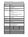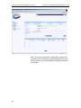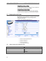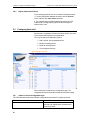
1
Solwise Ltd.
Set-up instructions for
Asus SL6000 VPN ADSL Router
www.solwiseforum.co.uk
The Solwise Forum is designed to be the first port-of-call for technical support and sales advice for the whole
Solwise product range.
Please check the forum for coverage on any technical problems you have. Many people have trodden your path
before you, and a quick check on the forum will reduce the pressure on our support staff.
Revision 0.03
September 24 2003
Chapter 1. Introduction
Solwise Asus SL6000 ADSL Ethernet Router User’s Guide
Notification is hereby given that Solwise Ltd. reserves the right to modify, change, update or revise this
document from time to time as required without the prior obligation to notify any person, company or
organization. Further, Solwise makes no warranty or representation, either express or implied, with respect
to merchantability, or fitness of its products for a particular purpose.
Solwise
Ltd.
13/15 Springfield Way
Anlaby
Hull HU10 6RJ
UK
Tel 0845 458 4558 (local rate)
Fax 0845 458 4559
Tech Support Tel 0845 1931320
SBV 1100
Email [email protected]
Http www.solwise.co.uk
Copyright
All rights reserved. No part of this document may be reproduced in any form or by any means without
written permission from the product manufacturer.
Changes are periodically made to the information in this document. They will be incorporated in
subsequent editions. The product manufacturer may take improvement and/or changes in the product
described in this document at any time.
FCC compliance
This equipment complies with Part 68 of the FCC Rules. On this equipment is a label that contains, among
other information, the FCC registration number and Ringer Equivalence Number (REN) for this equipment.
You must, upon request, provide this information to your telephone company.
If your telephone equipment causes harm to the telephone network, the Telephone Company may
discontinue your service temporarily. If possible, they will notify in advance. But, if advance notice isn’t
practical, you will be notified as soon as possible. You will be informed of your right to file a complaint with
the FCC.
Your telephone company may make changes in its facilities, equipment, operations, or procedures that could
affect proper operation of your equipment. If they do, you will be notified in advance to give you an
opportunity to maintain uninterrupted telephone service. The FCC prohibits this equipment to be connected
to party lines or coin-telephone service.
In the event that this equipment should fail to operate properly, disconnect the equipment from the phone
line to determine if it is causing the problem. If the problem is with the equipment, discontinue use and
contact your dealer or vendor.
2
SL6000 User’s Guide
DOC compliance information
NOTICE: The Canadian Department of Communications label identifies certified equipment. This
certification means that the equipment meets certain telecommunications network protective, operational
and safety requirements. The Department does not guarantee the equipment will operate to the user’s
satisfaction.
Before installing this equipment, users ensure that it is permissible to be connected to the facilities of the
local Telecommunications Company. The equipment must also be installed using an acceptable method of
connection. The customer should be aware that compliance with the above conditions might not prevent
degradation of service in some situations.
Repairs to certified equipment should be made by an authorized Canadian maintenance facility designated
by the supplier. Any repairs or alterations made by the user to this equipment, or equipment malfunctions,
may give the telecommunications company cause to request the user to disconnect the equipment.
Users should ensure for their own protection that the electrical ground connections of the power utility,
telephone lines and internal metallic water pipe system, if present, are connected together. This precaution
may be particularly important in rural areas.
CAUTION: Users should not attempt to make such connections themselves, but should contact the
appropriate electric inspection authority, or electrician, as appropriate.
NOTICE: The Load Number (LN) assigned to each terminal device denotes the percentage of the total load
to be connected to a telephone loop which is used by the device, to prevent overloading. The termination on
a loop may consist of any combination of devices subject only to the requirement that the sum of the Load
Numbers of all the devices does not exceed 100.
European CTR 21 compliance
The equipment has been approved in accordance with Council Decision 98/482/EC for pan-European single
terminal connection to the public switched telephone network (PSTN). However, due to differences between
the individual PSTNs provided in different countries, the approval does not, of itself, give an unconditional
assurance of successful operation on every PSTN network termination point. In the event of problem, you
should contact your equipment supplier in the first instance.
3
Solwise Asus SL6000 ADSL Ethernet Router User’s Guide
Chapter 1. Introduction
Table of Contents
1
Introduction..........................................................8
1.1
Overview................................................................... 8
1.2
Specifications and Features ..................................... 8
1.3
What’s in the package? .......................................... 10
1.4
Front Panel ............................................................. 10
1.5
Rear Panel.............................................................. 11
2
Connecting to your network and line.................12
3
Setting up TCP/IP on your computer ................14
3.1
Installing TCP protocol on your PC ........................ 14
3.1.1
Introduction.................................................... 14
3.1.2 Configure the PC(TCP/IP settings) for
Window 98 and Windows ME................................. 14
3.1.3 Configure the PC (TCP/IP Settings) for
Windows 2000 ........................................................ 16
3.1.4 Configure the PC (TCP/IP settings) for
Windows XP ........................................................... 18
4
PPPoA Router configuration (For the UK) ........20
4.1
Connecting to the setup screens ............................ 20
4.2
Running the Set-up Wizard .................................... 21
4.3
Enabling NAT.......................................................... 31
4.4 Enabling outbound access through the
firewall............................................................................ 34
4.5
5
4.4.1
Modifying the existing rules ........................... 35
4.4.2
Creating an Allow All rule .............................. 37
Configuring Port Forwarding................................... 39
Configuring Firewall/NAT Settings ....................41
5.1 DoS (Denial of Service) Protection and
Stateful Packet Inspection ............................................. 41
5.2
Default ACL Rules .................................................. 41
5.3
Configuring Inbound ACL Rules............................. 42
5.3.1 Options in Inbound ACL Configuration
Page 42
5.3.2
Add Inbound ACL .......................................... 44
5.3.3
Modify Inbound ACL Rules............................ 45
5.3.4
Delete Inbound ACL Rules............................ 45
5.3.5
Display Inbound ACL Rules .......................... 46
5
Chapter 1. Introduction
Solwise Asus SL6000 ADSL Ethernet Router User’s Guide
5.4
Configuring Outbound ACL Rules .......................... 46
5.4.1 Options in Outbound ACL
Configuration Page................................................. 46
5.5
5.6
6
5.4.2
Add an Outbound ACL Rule.......................... 48
5.4.3
Modify Outbound ACL Rules......................... 49
5.4.4
Delete Outbound ACL Rules......................... 49
5.4.5
Display Outbound ACL Rules........................ 50
Configuring Service List.......................................... 50
5.5.1
Options in Service Configuration Page ......... 50
5.5.2
Add a Service ................................................ 51
5.5.3
Modify a Service ............................................ 51
5.5.4
Delete a Service ............................................ 51
5.5.5
View Configured Services ............................. 51
Firewall Statistics .................................................... 52
Configuring VPN ...............................................53
6.1
Default Parameters................................................. 53
6.2 9.2 Establish VPN Connection Using
Automatic Keying........................................................... 55
6.2.1 VPN Tunnel Configuration Parameters
for Automatic Keying............................................... 56
6.2.2 Add a Rule for VPN Connection Using
Pre-shared Key....................................................... 58
6.2.3
Modify VPN Rules ......................................... 60
6.2.4
Delete VPN Rules.......................................... 60
6.2.5
Display VPN Rules ........................................ 60
6.3 Establish VPN Connection Using Manual
Keys............................................................................... 61
6.3.1 VPN Tunnel Configuration Parameters
– Manual Key.......................................................... 61
6.3.2 Add a Rule for VPN Connection Using
Manual Key............................................................. 62
6.4
7
Modify VPN Rules ......................................... 64
6.3.4
Delete VPN Rules.......................................... 64
6.3.5
Display VPN Rules ........................................ 64
VPN Statistics ......................................................... 65
The Configuration Pages in more detail............67
7.1
6
6.3.3
LAN......................................................................... 67
7.1.1
Ethernet ......................................................... 67
7.1.2
DHCP ............................................................ 68
Solwise Asus SL6000 ADSL Ethernet Router User’s Guide
Chapter 1. Introduction
7.2
WAN ....................................................................... 69
7.2.1
ADSL ............................................................. 69
7.2.2
Channel ......................................................... 70
7.3
Networking.............................................................. 74
7.3.1
DNS Server ................................................... 74
7.3.2
DNS Relay..................................................... 75
7.3.3
Routing .......................................................... 76
7.4
Firewall.................................................................... 77
7.4.1
Inbound ACL.................................................. 77
7.4.2
Outbound ACL............................................... 80
7.4.3
Group ACL..................................................... 83
7.4.4
Self Access.................................................... 86
7.4.5
Service........................................................... 87
7.4.6
DOS............................................................... 88
7.4.7
Policy List....................................................... 89
7.5
VPN ........................................................................ 98
7.5.1
Tunnel............................................................ 98
7.6
Log........................................................................ 102
7.7
System Management............................................ 103
7.7.1
Global Setting .............................................. 103
7.7.2
User Account ............................................... 104
7.7.3
Time Zone ................................................... 105
8
Command Line Interface mode ......................106
9
Appendix A IP Addresses, Network
Masks, and Subnets.....................................111
9.1
IP Addresses ........................................................ 111
9.1.1
Structure of an IP address........................... 111
9.1.2
Network classes .......................................... 112
9.2
10
Subnet masks....................................................... 112
Appendix B Binary Numbers...........................115
10.1
Binary Numbers................................................... 115
10.1.1
Bits and bytes ............................................ 115
11
Appendix C Glossary ......................................117
12
Appendix D Resetting to Defaults using
the Reset Button...........................................124
7
1 Introduction
1.1
Overview
The ASUS ADSL Router features multi-mode ADSL technology that
provides a downstream rate of up to 8M bps over existing copper
wire lines, which is more than 100 times faster than a traditional 56K
analogue modem. The SL6000 model can be connected to your PC
or LAN through the 10/100Base-T Ethernet interface and includes a
4-port 10/100 switching hub
It is designed to meet both the needs of single user, and multiple
users at small office and home office who want fast Internet access.
A wide variety of features and interoperability offer scalability and
flexibility for all the applications
1.2
Specifications and Features
ADSL Specifications
Line Coding
Standard Compliant
Data Rate
Rate Adaption
ATM Specification
ATM Adaptation Layer
VCs
Service Class
OAM
Basic Protocol
RFC 1483
RFC 2364
RFC2516
RFC 1577
RFC 1661
RFC 1332
RFC 1334
RFC 1994
Discrete Multi-Tone (DMT)
Full rate ADSL ANSI T1.413 Issue 2
ITU G.992.1 (G.dmt) Annex A, B
Splitterless G.992.2 (G.lite)
ITU G.994.1, G.996.1
Maximum transmission rate: Downstream up to 8 Mbps, and Upstream
up to 800 kbps
Data rate auto-negotiate in 32 kbps increments
Support AAL5, AAL2
Support 8 Permanent Virtual Circuits (PVCs)
UBR, CBR, rt-VBR, nrt-VBR
ITU-T I.610 OAM Principles & Functions F4, F5
Multiple protocol encapsulation over AAL5:
Support Logical Link Control (LLC) encapsulation
Support VC-based multiplexing
Support Bridged and Routing
PPP over AAL5:
Support LLC encapsulation
Support VC-based multiplexing
Support PPP over Ethernet Relay
Support PPP over Ethernet
Classical IP & ARP over ATM
PPP Link Control Protocol (LCP)
Internet Protocol Control Protocol (IPCP)
PPP Authentication Protocol (PAP)
PPP Challenge Handshake Authentication Protocol (CHAP)
8
Solwise Asus SL6000 ADSL Ethernet Router User’s Guide
Chapter 1. Introduction
Bridged Function (ADSL)
IEEE802.1d
Transparent bridge with spanning tree support.
PPPoE relay
Security features
Firewall
NAT (RFC1631)
Packet Filtering Method: SPI (Stateful Packet Inspection)
ACL (Access Control List)
DOS (Denial of Service)
Logging and Reporting
Static NAT, Dynamic NAT
Port-level NAT: PAT (Port Address Translation)
Virtual Server
IKE (Internet Key Exchange) Security Association (SA) assignment
Manual Key
Pre-shared Key
Perfect Forward Secrecy: D-H 1/2(Diffie-Hellman group 1/2)
IKE Mode: Main/Quick/Aggressive
VPN
Performance
IPSec (IP security)
AH/ESP (Authentication Header/Encryption Security Payload)
IPSec encryption algorithm: DES (56-bit)/3DES (168-bit)
Authentication Algorithms: MD5, SHA-1
VPN: Up to 60Mbps
Firewall: 100Mbps
NAT: Up to 90Mbps
Routing
IP Routing
PPPoE
LAN Service
WAN Service
Other Features
Management
Led indication
Power
WAN link
WAN tx/rx
LAN tx/rx
Interface Port
LAN
WAN
RS 232
Dimensions
Height
Width
Sub-Protocol: TCP, UDP, ICMP, ARP, RIPv1, and RIPv2
Static Routes: User definable (at least 8 static routes)
RFC2516
DHCP Server
DNS Proxy (Relay)
DHCP Client
Configuration through menu driven console via RS232 (Optional)
Configuration through Web interface (GUI)
Configuration through Telnet sessions (Optional)
SNMPv1 and MIB II support, ILMI4.0
Implement Log & Trace function
on
off
flashing
Power On
Power down
N/A
ADSL line up
ADSL line disconnect
Handshaking
N/A
No data transmission
Data transmission
LAN enable
LAN disable
Data transmission
4 RJ-45 ports for 10/100 Base-T Ethernet connection
One RJ11 port to connect to ADSL.
One RS-232 port for console management
34.6 mm (1.36 inches)
202.95 mm (7.99 inches)
9
Chapter 1. Introduction
Solwise Asus SL6000 ADSL Ethernet Router User’s Guide
Depth
Weight
Power Supply
182.5 mm (7.18 inches)
485g
Input Voltage
AC 230V, 50Hz (For EURO Region)
Power Consumption
Operating Environment
Operating Temperature
Non-Operating
Temperature
Humidity
15VAC, 700mA
Regulatory Agency
Compliance
1.3
0 C to 40 C (32F to 104F)
-20 C to 65 C (-4F to 149F)
5 % to 95 % (non-condensing)
FCC, CE, UL
What’s in the package?
One ADSL Router
One 15VAC Adapter
One RJ-11 Telephone Cable
One 10Base-T Ethernet straight-through Cable
One Software CD containing the User’s Guide and configuration software
1.4
Front Panel
LED Indicators
The VPN ADSL Router-modem is equipped with LEDs on the front
panel as described in the table below (from left to right):
10
Label
Color
Function
POWER
green
On: Unit is powered
on Off: Unit is
powered off
ALARM
green
Used in factory for
testing purpose.
Solwise Asus SL6000 ADSL Ethernet Router User’s Guide
Chapter 1. Introduction
WAN
green
On: WAN link
established and
active Flashing:
Data is transmitted
via WAN
connection
LAN1
green
On: LAN link is
established
Off: No WAN link
LAN2
Flashing: Data is
transmitted via LAN
connection
LAN3
LAN4
Off: No LAN link
1.5
Rear Panel
The SL6000 Router-modem is equipped with connections on the
back panel as described in the table below (from left to right):
Label
Function
On Off
Switches the unit on and off
Power
Connects to the supplied power
adapter
Reset
Resets the device
WAN
Connects to your WAN device,
such as ADSL or cable modem.
LAN1 – LAN4
Connects the device to your PC's
Ethernet port, or to the uplink port
on your LAN's hub/switch, using
the cable provided
11
Chapter 2. Connecting to your network and line
Solwise Asus SL6000 ADSL Ethernet Router User’s Guide
2 Connecting to your network and line
Step 1. Connect the ADSL modem.
For SL-6000/6300: Connect one end of the Line cable to the port
labeled ADSL on the rear panel of the device. Connect the other
end to the ADSL port on the splitter or micro-filter.
Step 2. Connect the computers or a LAN.
If your LAN has no more than 4 computers, you can use Ethernet
cable to connect computers directly to the built-in switch on the
device. Note that you should attach one end of the Ethernet cable to
any of the port labeled LAN1 – LAN4 on the rear panel of the device
and connect the other end to the Ethernet port of a computer.
If your LAN has more than 4 computers, you can attach one end of
a Ethernet cable to a hub or a switch (probably an uplink port;
please refer to the hub or switch documentations for instructions)
and the other to the Ethernet switch port (labeled LAN1 – LAN4) on
the SL-6000/6300.
Note that both the cross-over or straight-through Ethernet cable can
be used to connect the built-in switch and computers, hubs or
switches as the built-in switch is smart enough to make connections
with either type of cables.
Step 3. Attach the power adapter.
Connect the AC power adapter to the POWER connector on the
back of the device and plug in the adapter to a wall outlet or a
power strip.
Step 4. Turn on the SL-6000, the ADSL modem and power up your
computers.
Press the Power switch on the rear panel of SL-6000 to the ON
position. Turn on your ADSL or cable modem. Turn on and boot up
your computer(s) and any LAN devices such as hubs or switches.
12
Solwise Asus SL6000 ADSL Ethernet Router User’s Guide
Chapter 2. Connecting to your network and line
13
Chapter 3. Setting up TCP/IP on your computer
Solwise Asus SL6000 ADSL Ethernet Router User’s Guide
3 Setting up TCP/IP on your computer
You first of all need to check the TCP/IP settings of your computer.
Please note that the author is assuming you are using MS Windows
(Win9x or 2K/XP) or Mac OS10; please make appropriate
allowances if using another operating system or platform such as
Linux. The default IP address of the ASUS router is 192.168.7.1 on
subnet mask 255.255.255.0. In simple terms this means that, in
order for your computer to talk to the router, their IP address should
be in the range from 192.168.7.2 to 192.168.7.254. If you already
use TCP as your default network protocol and you don’t use IP
settings in the required range then you will have to either
permanently alter the settings of your computers to suite or change
the default address of the router. If you wish to alter the settings of
all your computers to suite then it is probably best to ask the person
in charge of your network set-up to do this for you. If you want to
alter the router then you will have to temporarily change the settings
for your PC.
3.1
3.1.1
Installing TCP protocol on your PC
Introduction
You will need to configure your computers to communicate with the
ADSL Router-modem. To do this, you will need to configure your
PC’s network setting to obtain an IP address automatically (by
default the SL6000 is configured to act as DHCP server).
Computers use IP address to communicate with each other across
a network or the internet.
Find out which operating system your computer is running, such as
Windows 98 SE, Windows Me, Windows 2000 or Windows XP.
You will need to know which operating system your computer is
running. You can find out by click on Start ->Settings. (If your Start
menu doesn’t have a Setting option, you are running Windows XP.
You can select the Control Panel directly from the Start menu.)
Then, click on Control Panel and double-click on the System icon.
Click the Cancel button when done.
Once you know which operating system you are running, follow the
directions in this step for your computer’s operation system.
The next few pages tell you, step by step, ho w to configure your
TCP/IP setting based on the type of Window operating system you
are using.
3.1.2
Configure the PC(TCP/IP settings) for Window 98 and Windows ME
1. Click on Start -> Settings -> Control Panel. Double-click on the
Network icon to open the Network screen.
2. Select the Configuration tab and highlight the TCP/IP line for
the applicable Ethernet adapter. If the word TCP/IP appears by
14
Solwise Asus SL6000 ADSL Ethernet Router User’s Guide
Chapter 3. Setting up TCP/IP on your computer
itself, select that line. Click on Properties.
3. Click the IP Address tab and select Obtain and IP address
automatically.
4. Click on the Gateway tab and verify that the Installed Gateway
field is blank. Click on OK.
5. Click again on OK. Windows may as you for the original
Windows installation disk or additional files. Supply them by pointing
to the correct location, e.g.D:\win98, where “D” represents the letter
of your CD-ROM drive.
6. If Windows asks you to restart you PC, click on Yes. If Windows
does not ask you to restart, restart your computer anyway.
15
Chapter 3. Setting up TCP/IP on your computer
3.1.3
Solwise Asus SL6000 ADSL Ethernet Router User’s Guide
Configure the PC (TCP/IP Settings) for Windows 2000
1. Click on Start -> Settings -> Control Panel. Double-click on the
Network and Dial-up Connection icon. The Network screen will
appear.
2. Select the Local Area Connection icon for the applicable
Ethernet adapter (usually it is the first Local Area Connection listed).
Double-click on Local Area Connection and click Properties.
16
Solwise Asus SL6000 ADSL Ethernet Router User’s Guide
Chapter 3. Setting up TCP/IP on your computer
3. Select Internet Protocol (TCP/IP) and click on Properties.
4. Select Obtain an IP address automatically and click on OK on
the subsequent screens to complete the PC’s configuration.
5. Restart your computer.
17
Chapter 3. Setting up TCP/IP on your computer
3.1.4
Solwise Asus SL6000 ADSL Ethernet Router User’s Guide
Configure the PC (TCP/IP settings) for Windows XP
The following instructions assume you are running Windows XP’s
default interface. If you are using the Classical interface (where the
icons and menus look like previous Windows versions) , please
follow the instructions for Windows 2000(step 3b).
1. Click on Start-> Control Panel. Click on the Network and
Internet Connections icon. Click on the Network Connections
icon. The Network screen will appear.
2. Select the Local Area Connection icon for the applicable
Ethernet adapter (usually it is the first Local Area Connection listed.)
Double click on Local Area Connection and click on Properties.
18
Solwise Asus SL6000 ADSL Ethernet Router User’s Guide
Chapter 3. Setting up TCP/IP on your computer
3. Select Obtain an IP address automatically and click on OK on
the subsequent screens to complete the PC’s configuration.
4. Restart your computer.
19
Chapter 4. PPPoA Router configuration (For the UK)
Solwise Asus SL6000 ADSL Ethernet Router User’s Guide
4 PPPoA Router configuration (For the UK)
The SL-6000/6300 provides a preinstalled software program called
Configuration Manager that enables you to configure SL-6000/6300
via your Web browser.
To configure using your browser you must first of all must have
successfully installed TCP/IP protocol on your computer as detailed
above.
After checking your connections and TCP settings (see above) you
are ready to run your browser in order to configure the router.
Any browser can be used on any operating system: The
configuration screens are the same.
4.1
Connecting to the setup screens
Start your browser and enter IP address of SL6000 (default
192.168.1.1) on the address line in your browser and then enter the
default configuration login username/password admin/admin:
20
Solwise Asus SL6000 ADSL Ethernet Router User’s Guide
4.2
Chapter 4. PPPoA Router configuration (For the UK)
Running the Set-up Wizard
Now run the Set-up Wizard…. Click on Next.
21
Chapter 4. PPPoA Router configuration (For the UK)
Solwise Asus SL6000 ADSL Ethernet Router User’s Guide
Unless you want to change the configuration passwords used
(admin/admin) then click Next.
22
Solwise Asus SL6000 ADSL Ethernet Router User’s Guide
Chapter 4. PPPoA Router configuration (For the UK)
Unless you want to change the System Configuration then just click
on Next…
23
Chapter 4. PPPoA Router configuration (For the UK)
Solwise Asus SL6000 ADSL Ethernet Router User’s Guide
The Time Zone screen allows you to alter the date/time settings. If
you want change these values and then click on Next….
24
Solwise Asus SL6000 ADSL Ethernet Router User’s Guide
Chapter 4. PPPoA Router configuration (For the UK)
You can now alter the LAN IP settings if you want. Click on Next
when finished…
25
Chapter 4. PPPoA Router configuration (For the UK)
Solwise Asus SL6000 ADSL Ethernet Router User’s Guide
The next screen allows you to alter the DHCP server settings. If you
are happy with them just click on Next.
26
Solwise Asus SL6000 ADSL Ethernet Router User’s Guide
Chapter 4. PPPoA Router configuration (For the UK)
You now need to configure the WAN configuration…
For a BT line set-up select ‘PPoA Routed’, VPI 0, VCI 38, VC
MUX, Default Gateway ticked…
27
Chapter 4. PPPoA Router configuration (For the UK)
Solwise Asus SL6000 ADSL Ethernet Router User’s Guide
For a KC line set-up select ‘PPoA Routed’, VPI 1, VCI 50,
LLC/SNAP, Default Gateway ticked…
28
Solwise Asus SL6000 ADSL Ethernet Router User’s Guide
Chapter 4. PPPoA Router configuration (For the UK)
Then click on Add…
29
Chapter 4. PPPoA Router configuration (For the UK)
Solwise Asus SL6000 ADSL Ethernet Router User’s Guide
Now, if your router is connected to a valid ADSL connection and
you have set-up for ‘Automatic IP Address Assignment’ the router
should connect to your ISP and display the connection IP address.
For example:
30
Solwise Asus SL6000 ADSL Ethernet Router User’s Guide
4.3
Chapter 4. PPPoA Router configuration (For the UK)
Enabling NAT
Now you need to enable NAT. You do this by creating an NAT
POOL. Goto Firewall/Policy List/Nat Pool:
31
Chapter 4. PPPoA Router configuration (For the UK)
Solwise Asus SL6000 ADSL Ethernet Router User’s Guide
Make a new NAT Pool of type Interface and select the new PPPoA
Routed Interface.
32
Solwise Asus SL6000 ADSL Ethernet Router User’s Guide
Chapter 4. PPPoA Router configuration (For the UK)
Then Add the entry:
33
Chapter 4. PPPoA Router configuration (For the UK)
4.4
Solwise Asus SL6000 ADSL Ethernet Router User’s Guide
Enabling outbound access through the firewall
Now we need to modify/create the Outbound ACL (Access Control
Configuration). Goto Firewall/Outbound ACL…
34
Solwise Asus SL6000 ADSL Ethernet Router User’s Guide
Chapter 4. PPPoA Router configuration (For the UK)
By default the standard Outbound ACL rules are set for NAT
applied to the WAN interface. However, for operation with a NAT
Pool (as created above) you need to alter these rules to apply to the
NAT Pool.
So, you have two options: You could modify the existing rules or
you can just create a new ‘Allow All’ rule (though, of course, an
‘allow all rule’ will effectively turn your firewall off).
4.4.1
Modifying the existing rules
To modify the rules simply click on the pencil next to each rule (e.g.
the POP3 rule):
35
Chapter 4. PPPoA Router configuration (For the UK)
Solwise Asus SL6000 ADSL Ethernet Router User’s Guide
Now change the NAT Type to NAT Pool and select the new pool
you have created:
36
Solwise Asus SL6000 ADSL Ethernet Router User’s Guide
Chapter 4. PPPoA Router configuration (For the UK)
Now click on Modify. You will need to do all the rules to enable full,
standard access.
4.4.2
Creating an Allow All rule
Your alternative is to create an Allow All rule. To do this create a
rule like this…
37
Chapter 4. PPPoA Router configuration (For the UK)
Then Add the rule
38
Solwise Asus SL6000 ADSL Ethernet Router User’s Guide
Solwise Asus SL6000 ADSL Ethernet Router User’s Guide
Chapter 4. PPPoA Router configuration (For the UK)
Now, internet access should work! If it doesn’t work then check on
the WAN ADSL screen that it shows you are connected. If not then
this says it can’t find the ADSL signal on the line. Next goto the
WAN//Channel page and make sure it shows an IP address for the
link: Address 0.0.0.0 is NOT correct. If there is no address shown
then this means it’s not logging in with the ISP. Check your user
name and password. Finally check that your PC is running with
correct IP, Default gateway and DNS addresses.
4.5
Configuring Port Forwarding
Goto Firewall/Inbound ACL…
Create a rule which specifies the source and destination ports and
also the IP address of the system you want the traffic forwarded to.
For example, if you wanted to forward port 80 (http) to a local client
at address 192.168.0.49 then…
39
Chapter 4. PPPoA Router configuration (For the UK)
That’s it ☺
40
Solwise Asus SL6000 ADSL Ethernet Router User’s Guide
Solwise Asus SL6000 ADSL Ethernet Router User’s Guide
Chapter 5. Configuring Firewall/NAT Settings
5 Configuring Firewall/NAT Settings
SL-6000 provides built-in firewall/NAT functions, enabling you to
protect the system against denial of service (DoS) attacks and other
types of malicious accesses to your LAN while providing Internet
access sharing at the same time. You can also specify how to
monitor attempted attacks, and who should be automatically
notified.
This chapter describes how to create/modify/delete ACL (Access
Control List) rules to control the data passing through your network.
You will use firewall configuration pages to:
Create, modify and delete inbound/outbound ACL rules.
Create, modify and delete pre-defined services to be used
in inbound/outbound ACL configurations.
View ACL inbound/outbound rules
View firewall statistics.
Note: •When you define an ACL rule, you instruct the SL-6000 to
examine each data packet it receives to determine whether it meets
criteria set forth in the rule. The criteria can include the network or
internet protocol it is carrying, the direction in which it is traveling (for
example, from the LAN to the Internet or vice versa), the IP address
of the sending computer, the destination IP address, and other
characteristics of the packet data. If the packet matches the criteria
established in a rule, the packet can either be accepted (forwarded
towards its destination), or denied (discarded), depending on the
action specified in the rule.
5.1
DoS (Denial of Service) Protection and Stateful Packet Inspection
The firewall as implemented in SL-6000 provides DoS protection
and stateful packet inspection as the first line security for your
network. No configuration is required for this protection on your
network as long as firewall is enabled for SL-6000. By default, the
firewall is enabled at the factory.
5.2
Default ACL Rules
SL-6000 supports three types of default access rules:
Inbound Access Rules: for controlling incoming access to
computers on your LAN.
Outbound Access Rules: for controlling outbound access to
external networks for hosts on your LAN.
Self Access Rules: for controlling access to SL-6000 itself.
41
Chapter 5. Configuring Firewall/NAT Settings
Solwise Asus SL6000 ADSL Ethernet Router User’s Guide
Default Inbound Access Rules
No default inbound access rule is configured. That is, all traffic from
external hosts to the internal hosts is denied.
Default Outbound Access Rules
The default outbound access rule allows all the traffic originated
from your LAN to be forwarded to the external network using NAT.
5.3
Configuring Inbound ACL Rules
By creating ACL rules in Inbound ACL configuration page as shown
below, you can control (allow or deny) incoming access to
computers on your LAN.
Options in this configuration page allow you to:
Add a rule, and set parameters for it
Modify an existing rule
Delete an existing rule
View configured ACL rules
5.3.1
Options in Inbound ACL Configuration Page
Option
ID
Add New
Rule Number
Action
42
Purpose
Click on this option to add a new 'basic' Firewall
rule.
Select a rule from the drop-down list, to modify its
attributes.
Solwise Asus SL6000 ADSL Ethernet Router User’s Guide
Allow
Deny
Chapter 5. Configuring Firewall/NAT Settings
Select this button to configure the rule as an allow
rule.
This rule when bound to the Firewall will allow
matching packets to pass through.
Select this button to configure the rule as a deny
rule.
This rule when bound to the Firewall will not allow
matching packets to pass through.
Move to
This option allows you to set a priority for this rule. TheSL-6000 Firewall acts on packets based on the
priority of the rules. Set a priority by specifying a number for its position in the list of rules:
1 (First)
This number marks the highest priority.
Other numbers
Select other numbers to indicate the priority you
wish to assign to the rule.
Source IP
This section allows you to set the source network to which this rule should apply. Use the drop-down list
to select one of the following:
Any
This option allows you to apply this rule inclusively
on all computers in the external network.
IP Address
This option allows you to specify an IP address on
which this rule will be applied.
IP Address
Specify the appropriate network address
Subnet
This option allows you to include all the computers
that are connected in an IP subnet. When this
option is selected, the following fields become
available for entry:
Address
Enter the appropriate IP address.
Mask
Enter the corresponding subnet mask.
Range
This option allows you to include a range of IP
addresses for applying this rule.
The following fields become available for entry
when this option is selected:
Begin
Enter the starting IP address of the range
End
Enter the ending IP address of the range
Destination IP
This section allows you to set the destination network to which this rule should apply. Use the drop-down
list to select one of the following:
Any
This option allows you to apply this rule inclusively
on all computers in the local network.
IP Address, Subnet, Range
Select any of these and enter details as described
in the Source IP section above.
Source Port
Any
Select this option if you want this rule to apply to
all applications with an arbitrary source port
number.
Single
This option allows you to apply this rule to an
application with a specific source port number.
Port Number
Enter the source port number
Range
Select this option if you want this rule to apply to
applications with this port range. The following
fields become available for entry when this option
is selected.
43
Chapter 5. Configuring Firewall/NAT Settings
Begin
End
Destination Port
Any
Single, Range
Service
Solwise Asus SL6000 ADSL Ethernet Router User’s Guide
Enter the starting port number of the range
Enter the ending port number of the range
Select this option if you want this rule to apply to
all applications with an arbitrary destination port
number.
Select any of these and enter details as described
in the Source Port section above.
This option allows you to select any of the preconfigured services (selectable from the dropdown list) instead of the destination port. The
following are examples of services:
BATTLE-NET, PC-ANYWHERE, FINGER,
DIABLO-II, L2TP, H323GK, CUSEEME, MSNZONE, ILS, ICQ_2002, ICQ_2000, MSN, AOL,
RPC, RTSP7070, RTSP554, QUAKE, N2P, PPTP,
MSG2, MSG1, IRC, IKE, H323, IMAP4, HTTPS,
DNS, SNMP, NNTP, POP3, SMTP, HTTP, FTP,
TELNET.
Note: service is a combination of protocol and port
number. They appear here after you add them in
the “Firewall Service” configuration
Port Mapping
Select “IP Address” if you want to direct the incoming traffic to a specific computer (usually a server
such as web server) in your LAN; otherwise, select “None”.
None
Select this option to not use NAT.
IP Address
Select this option to specify the IP address of the
computer that you want the incoming traffic to be
directed.
Log
Select “Enable” radio button to enable logging for
this ACL rule; otherwise, select “Disable”.
VPN
This option allows you to select the check box if
this policy corresponds to VPN policy.
5.3.2
Add Inbound ACL
To add an inbound ACL rule, follow the instructions below:
1. Log into Configuration Manager as admin, click the Firewall
menu, and then click Inbound ACL submenu. The Firewall Inbound
ACL Configuration page displays, as shown in Figure 8.1.
Note that when you open the Inbound ACL Configuration page, a
list of existing ACL rules are also displayed in the lower half of the
configuration page such as those shown in Figure 8.2.
2. Select “Add New” from the “ID” drop-down list.
3. Set desired action (Allow or Deny) from the “Action” drop-down
list.
4. Make changes to any or all of the following fields:
source/destination IP, source/destination port, protocol, port
mapping, log, and VPN. Please see Table 8.1 for explanation of
these fields.
44
Solwise Asus SL6000 ADSL Ethernet Router User’s Guide
Chapter 5. Configuring Firewall/NAT Settings
5. Assign a priority for this rule by selecting a number from the
“Move to” drop-down list. Note that the number indicates the priority
of the rule with 1 being the highest. Higher priority rules will be
examined prior to the lower priority rules by the firewall.
6. Click on the Add button to create the new ACL rule. The new
ACL rule will then be displayed in the inbound access control list
table at the lower half of the Inbound ACL Configuration page.
Figure 8.2 illustrates how to create a rule to allow inbound HTTP
(i.e. web server) service. This rule allows inbound HTTP traffic to be
5.3.3
Modify Inbound ACL Rules
To modify an inbound ACL rule, follow the instructions below:
1. Log into Configuration Manager as admin, click the Firewall
menu, and then click Inbound ACL submenu.
2. Select the rule number from the “ID” drop-down list or click on the
icon of the rule to be modified in the inbound ACL table.
3. Make desired changes to any or all of the following fields: action,
source/destination IP, source/destination port, protocol, port
mapping, log, and VPN. Please see Table 8.1 for explanation of
these fields.
4. Click on the Modify button to modify this ACL rule. The new
settings for this ACL rule will then be displayed in the inbound
access control list table at the lower half of the Inbound ACL
Configuration page.
5.3.4
Delete Inbound ACL Rules
To delete an inbound ACL rule, follow the instructions below:
1. Log into Configuration Manager as admin, click the Firewall
menu, and then click Inbound ACL submenu.
2. Select the rule number from the “ID” drop-down list or click on the
icon of the rule to be deleted in the inbound ACL table.
45
Chapter 5. Configuring Firewall/NAT Settings
Solwise Asus SL6000 ADSL Ethernet Router User’s Guide
3. Click on the Delete button to delete this ACL rule. Note that the
ACL rule deleted will be removed from the ACL rule table located at
the lower half of the same configuration page.
5.3.5
Display Inbound ACL Rules
To see existing inbound ACL rules, follow the instructions below:
1. Log into Configuration Manager as admin, click the Firewall
menu, and then click Inbound ACL submenu.
2. The inbound ACL rule table located at the lower half of the
Inbound ACL Configuration page shows all the configured inbound
ACL rules.
5.4
Configuring Outbound ACL Rules
By creating ACL rules in outbound ACL configuration page as
shown in Figure 8.3, you can control (allow or deny) Internet or
external network access for computers on your LAN.
Options in this configuration page allow you to:
Add a rule, and set parameters for it
Modify an existing rule
Delete an existing rule
View configured ACL rules
5.4.1
Options in Outbound ACL Configuration Page
The Table below describes the options available for an outbound ACL rule.
Option
Purpose
ID
Add New
Click on this option to add a new 'basic' Firewall
rule.
Rule Number
Select a rule from the drop-down list, to modify its
attributes.
46
Solwise Asus SL6000 ADSL Ethernet Router User’s Guide
Chapter 5. Configuring Firewall/NAT Settings
Action
Allow
Select this button to configure the rule as an allow
rule.
This rule when bound to the Firewall will allow
matching packets to pass through.
Deny
Select this button to configure the rule as a deny
rule.
This rule when bound to the Firewall will not allow
matching packets to pass through.
Move to This option allows you to set a priority for this rule. The SL-6000 Firewall acts on packets based
on the priority of the rules. Set a priority by specifying a number for its position in the list of rules:
1 (First)
Other numbers
This number marks the highest priority.
Select other numbers to indicate the priority you
wish to assign to the rule.
Source IP
This section allows you to set the source network to which this rule should apply. Use the drop-down list
to select one of the following:
Any
This option allows you to apply this rule inclusively
on all computers in the external network.
IP Address
This option allows you to specify an IP address on
which this rule will be applied.
IP Address
Specify the appropriate network address
Subnet
This option allows you to include all the computers
that are connected in an IP subnet. When this
option is selected, the following fields become
available for entry:
Address
Enter the appropriate IP address.
Mask
Enter the corresponding subnet mask.
Range
This option allows you to include a range of IP
addresses for applying this rule.
The following fields become available for entry
when this option is selected:
Begin
Enter the starting IP address of the range
End
Enter the ending IP address of the range
Destination IP
This section allows you to set the destination network to which this rule should apply. Use the drop-down
list to select one of the following:
Any
This option allows you to apply this rule inclusively
on all computers in the local network.
IP Address, Subnet, Range
Select any of these and enter details as described
in the Source IP section above.
Source Port
Any
Select this option if you want this rule to apply to all
applications with an arbitrary source port number.
Single
This option allows you to apply this rule to an
application with a specific source port number.
Port Number
Enter the source port number
Range
Select this option if you want this rule to apply to
applications with this port range. The following
fields become available for entry when this option
47
Chapter 5. Configuring Firewall/NAT Settings
Solwise Asus SL6000 ADSL Ethernet Router User’s Guide
is selected.
Begin
End
Destination Port
Any
Enter the starting port number of the range
Enter the ending port number of the range
Select this option if you want this rule to apply to all
applications with an arbitrary destination port
number.
Select any of these and enter details as described
in the Source Port section above.
This option allows you to select any of the preconfigured services (selectable from the dropdown list) instead of the destination port. The
following are examples of services:
BATTLE-NET, PC-ANYWHERE, FINGER,
DIABLO-II, L2TP, H323GK, CUSEEME, MSNZONE, ILS, ICQ_2002, ICQ_2000, MSN, AOL,
RPC, RTSP7070, RTSP554, QUAKE, N2P, PPTP,
MSG2, MSG1, IRC, IKE, H323, IMAP4, HTTPS,
DNS, SNMP, NNTP, POP3, SMTP, HTTP, FTP,
TELNET.
Note: service is a combination of protocol and port
number. They appear here after you add them in
the “Firewall Service” configuration page.
Select “Enable” radio button to enable the use of
NAT; otherwise; select “Disable”
Select “Enable” radio button to enable logging for
this ACL rule; otherwise, select “Disable”.
This option allows you to select the check box if
this policy corresponds to VPN policy.
Single, Range
Service
NAT
Log
VPN
5.4.2
Add an Outbound ACL Rule
To add an outbound ACL rule, follow the instructions below:
1. Log into Configuration Manager as admin, click the Firewall
menu, and then click Outbound ACL submenu. The Firewall
Outbound ACL Configuration page displays, as shown above.
Note that when you open the Outbound ACL Configuration page, a
list of existing ACL rules are also displayed in the lower half of the
configuration page such as those shown above.
2. Select “Add New” from the “ID” drop-down list.
3. Set desired action (Allow or Deny) from the “Action” drop-down
list.
4. Make changes to any or all of the following fields:
source/destination IP, source/destination port, protocol, port
mapping, log, and VPN. Please see Table above for explanation of
these fields.
5. Assign a priority for this rule by selecting a number from the
“Move to” drop-down list. Note that the number indicates the priority
of the rule with 1 being the highest. Higher priority rules will be
examined prior to the lower priority rules by the firewall.
48
Solwise Asus SL6000 ADSL Ethernet Router User’s Guide
Chapter 5. Configuring Firewall/NAT Settings
6. Click on the Add button to create the new ACL rule. The new
ACL rule will then be displayed in the outbound access control list
table at the lower half of the Outbound ACL Configuration page.
Figure above illustrates how to create a rule to allow outbound
HTTP traffic. This rule allows outbound HTTP traffic to be directed
to any host on the external network for a host in your LAN w/ IP
address 192.168.1.15.
5.4.3
Modify Outbound ACL Rules
To modify an outbound ACL rule, follow the instructions below:
1. Log into Configuration Manager as admin, click the Firewall
menu, and then click Outbound ACL submenu.
2. Select the rule number from the “ID” drop-down list or click on the
icon of the rule to be modified in the outbound ACL table.
3. Make desired changes to any or all of the following fields: action,
source/destination IP, source/destination port, protocol, port
mapping, log, and VPN. Please see Table above for explanation of
these fields.
4. Click on the Modify button to modify this ACL rule. The new
settings for this ACL rule will then be displayed in the outbound
access control list table at the lower half of the Outbound ACL
Configuration page.
5.4.4
Delete Outbound ACL Rules
To delete an outbound ACL rule, follow the instructions below:
1. Log into Configuration Manager as admin, click the Firewall
menu, and then click Outbound ACL submenu.
2. Select the rule number from the “ID” drop-down list or click on the
icon of the rule to be deleted in the outbound ACL table.
3. Click on the Delete button to delete this ACL rule. Note that the
ACL rule deleted will be removed from the ACL rule table located at
the lower half of the same configuration page.
49
Chapter 5. Configuring Firewall/NAT Settings
5.4.5
Solwise Asus SL6000 ADSL Ethernet Router User’s Guide
Display Outbound ACL Rules
To see existing outbound ACL rules, follow the instructions below:
1. Log into Configuration Manager as admin, click the Firewall
menu, and then click Outbound ACL submenu.
2. The outbound ACL rule table located at the lower half of the
Outbound ACL Configuration page shows all the configured
outbound ACL rules.
5.5
Configuring Service List
Services are a combination of Protocol and Port number. It is used
in inbound and outbound ACL rule configuration.
You may use Service Configuration Page to:
Add a service, and set parameters for it
Modify an existing service
Delete an existing service
View configured services
Service drop-down list
Above shows the Firewall Service Configuration page. The
configured services are listed at the lower half of the same page.
5.5.1
Options in Service Configuration Page
The Table below describes the available configuration parameters for firewall service list.
Field
Service Name
50
Action
Enter the name of the Service to be added.
Note that only alphanumeric characters are
allowed in a name.
Solwise Asus SL6000 ADSL Ethernet Router User’s Guide
Protocol
Port
5.5.2
Chapter 5. Configuring Firewall/NAT Settings
Enter the type of protocol the service uses.
Enter the port number that is set for this
service.
Add a Service
To add a service, follow the instructions below:
1. Log into Configuration Manager as admin, click the Firewall
menu, and then click Service submenu. The Firewall Service
Configuration page displays, as shown above.
Note that when you open the Service Configuration page, a list of
existing services are also displayed in the lower half of the
configuration page such as those shown above.
2. Select “Add New” from the service drop-down list.
3. Enter a desired name, preferably a meaningful name that
signifies the nature of the service, in the “Service Name” field. Note
that only alphanumeric characters are allowed in a name.
4. Make changes to any or all of the following fields: public port and
protocol. Please see above table for explanation of these fields.
5. Click on the Add button to create the new service. The new
service will then be displayed in the service list table at the lower
half of the Service Configuration page.
5.5.3
Modify a Service
To modify a service, follow the instructions below:
1. Log into Configuration Manager as admin, click the Firewall
menu, and then click Service submenu.
2. Select the service from the service drop-down list or click on the
icon of the service to be modified in the service list table.
3. Make desired changes to any or all of the following fields: service
name, public port and protocol. Please see table above for
explanation of these fields.
4. Click on the Modify button to modify this service. The new
settings for this service will then be displayed in the service list table
at the lower half of the Service Configuration page.
5.5.4
Delete a Service
To delete a service, follow the instructions below:
1. Log into Configuration Manager as admin, click the Firewall
menu, and then click Service submenu.
2. Select the service from the service drop-down list or click on the
icon of the service to be modified in the service list table.
3. Click on the Delete button to delete this service. Note that the
service deleted will be removed from the service list table located at
the lower half of the same configuration page.
5.5.5
View Configured Services
To see a list of existing services, follow the instructions below:
51
Chapter 5. Configuring Firewall/NAT Settings
Solwise Asus SL6000 ADSL Ethernet Router User’s Guide
1. Log into Configuration Manager as admin, click the Firewall
menu, and then click Service submenu.
2. The service list table located at the lower half of the Service
Configuration page shows all the configured services.
5.6
Firewall Statistics
The Firewall Statistics page displays details regarding the active
connections. Figure below shows a sample firewall statistics for
active connections. To see an updated statistics, click on Refresh
button.
52
Solwise Asus SL6000 ADSL Ethernet Router User’s Guide
Chapter 6. Configuring VPN
6 Configuring VPN
The chapter contains instructions for configuring VPN connections
using automatic keying and manual keys.
6.1
Default Parameters
The SL-6000 is pre-configured with a default set of
proposals/connections. They cover the most commonly used sets of
parameters, required for typical deployment scenarios. It is
recommended that you use these pre-configured
proposals/connections to simplify VPN connection setup. The
default parameters provided in the SL-6000 are as follows:
Default Connections
Each connection represents a rule that will be applied on traffic
originating from / terminating at the security gateway. It contains the
parameters: local/remote IP-Addresses and ports.
Table below lists the default connections that are provisioned on the
gateway:
Default connections in SL-6000
Name
allow-ike-io
Type
Passby
Port
500
allow-all
Passby
Protocol
UDP
State
Enabled
Enabled
Purpose
To allow the IKE traffic
to the SL-6000
To allow the plain
traffic
Proposals
Each proposal represents a set of authentication/encryption
parameters. Once configured, a proposal can be tied to a
connection. Upon session establishment, one of the proposals
specified is selected and used for the tunnel. Note that multiple
proposals can be specified for a connection. If you do not specify
the proposal to be used for a connection, all the pre-configured
proposals will be included for that connection.
Pre-configured IKE proposals
IKE proposals decide the type of encryption, hash algorithms and
authentication method that will be used for the establishment of the
session keys between the endpoints of a tunnel. Table 9.2 lists the
pre-configured IKE proposals.
Pre-configured IKE proposals in SL-6000
Name
Encryption
Algorithm
Authentication
Algorithm
DiffieHellman
Group
Key
Management
Life time
(secs)
53
Chapter 6. Configuring VPN
ike-preshared3des-sha1-dh2
ike-preshared3des-md5-dh2
ike-preshareddes-sha1-dh2
ike-preshareddes-md5-dh2
ike-preshared3des-sha1-dh1
ike-preshared3des-md5-dh1
ike-preshareddes-sha1-dh1
ike-preshareddes-md5-dh1
ike-preshared3des-sha1-dh5
ike-preshared3des-md5-dh5
ike-preshareddes-sha1-dh5
ike-preshareddes-md5-dh5
Solwise Asus SL6000 ADSL Ethernet Router User’s Guide
3DES
SHA-1
2
3DES
MD5
2
DES
SHA-1 2
DES
MD5
2
3DES
SHA-1
1
3DES
MD5
1
DES
SHA-1 1
DES
MD5
1
3DES
SHA-1
5
3DES
MD5
5
DES
SHA-1 5
DES
MD5
5
Pre-shared
Keys
Pre-shared
Keys
Pre-shared
Keys
Pre-shared
Keys
Pre-shared
Keys
Pre-shared
Keys
Pre-shared
Keys
Pre-shared
Keys
Pre-shared
Keys
Pre-shared
Keys
Pre-shared
Keys
Pre-shared
Keys
3600
3600
3600
3600
3600
3600
3600
3600
3600
3600
3600
3600
Pre-configured IPSec proposals
IPSec proposals decide the type of encryption and authentication of
the traffic that flows between the endpoints of the tunnel. Table
below lists the default IPSec proposals available on the SL-6000
Name
ipsec-esp-3des-sha1
ipsec-esp-3des-md5
ipsec-esp-des-sha1
ipsec-esp-des-md5
ipsec-ah-sha1
ipsec-ah-md5
ipsec-esp-3des
ipsec-esp-des
ipsec-esp-sha1
ipsec-esp-md5
Encryption
Algorithm
3DES
3DES
DES
DES
3DES
DES
-
Authentication
Algorithm
SHA-1
MD5
SHA-1
MD5
SHA-1
MD5
SHA-1
MD5
Encapsulation
ESP
ESP
ESP
ESP
AH
AH
ESP
ESP
ESP
ESP
Life time
(Mbytes/secs)
75/3600
75/3600
75/3600
75/3600
75/3600
75/3600
75/3600
75/3600
75/3600
75/3600
Default lifetime
Default lifetime for the pre-configured IKE proposals and IPSec
proposals is 3600 seconds. (One hour). It is recommended to set
lifetime value greater than 600 seconds, for a new IKE proposal or
IPSec proposal.
54
Solwise Asus SL6000 ADSL Ethernet Router User’s Guide
Chapter 6. Configuring VPN
This will reduce quick re-keying which will unnecessarily burden the
system.
Limits for key length
The maximum key length for pre shared key, cipher key and
Authentication Key is 50characters. If the cipher key length is
greater than the length specified by the encryption algorithm, the
key is truncated to the appropriate length.
Priority of the connections
The allow-ike-io default rule has the highest priority (1). The allow-all
default rule has the lowest priority. At any point of time it is
recommended to maintain this priority. If you add connections below
the allow-all rule (lower priority), it will not have any effect as the
corresponding packets will match the allow-all rule and go without
encryption.
Important:
Note that pre-configured Proposals/Connections are read-only and
cannot be modified. If you have to specify a proposal (other than the
default), you should add a new one via VPN configuration page.
This way you can control the proposals that become part of a
connection. Note: For the negotiation to succeed the peer gateway
should also be configured with matching parameters. However if
needed any specific proposal can be chosen.
This chapter includes the procedure to configure the Access List
through GUI:
Basic Access List Configuration
• Access List using IKE
• Access List using Manual Keys
Advanced Access List Configuration
• Access List using IKE
• Access List using Manual Keys
6.2
9.2 Establish VPN Connection Using Automatic Keying
This section describes the steps to establish the VPN tunnel using
the Configuration Manager. Internet Key Exchange (IKE) is the
automatic keying protocol used to exchange the key that is used to
encrypt/authenticate the data packets according to the userconfigured rule. The parameters that should be configured are:
the network addresses of internal and remote networks.
the remote gateway address and the local gateway
address.
pre-shared secret for remote gateway authentication.
appropriate priority for the connection.
This option sequence brings up the screen as illustrated in Figure
4.2. Fields and buttons represent the basic VPN parameters. Use
55
Chapter 6. Configuring VPN
Solwise Asus SL6000 ADSL Ethernet Router User’s Guide
them to configure basic Access Rule that will be used to establish a
tunnel from local secure group to remote secure group with basic
parameters.
Options in this screen allow you to:
Add an Access List, and set basic parameters for it
Modify an Access List
Delete an existing Access List
6.2.1
VPN Tunnel Configuration Parameters for Automatic Keying
Table below describes the VPN tunnel configuration parameters
using pre-shared key as key management mode.
Table 9.4. VPN tunnel configuration parameters using pre-shared key for key management
Options
What it means/ When to use
VPN Connection Settings
ID
Add New
Rule number
Name
Click on this option to add a new VPN rule.
Select a rule from the drop-down list, to modify its
attributes.
Enter a unique name, preferably a meaningful
name that signifies the tunnel connection. Note
that only alphanumeric characters are allowed in
this field.
Select this radio button to enable this rule (default).
Select this radio button to disable this rule.
Enable
Disable
Move to
This option allows you to set a priority for this rule. The VPN service in SL-6000 acts on packets based
on the priority of the rule, with 1 being the highest priority. Set a priority by specifying a number for its
position in the list of rules:
1
This number marks the highest priority.
Other numbers
Select other numbers to indicate the priority you
wish to assign to the rule.
Local Secure Group
This option allows you to set the local secure network to which this rule should apply. This option allows
you to apply this rule inclusively on all computers in the internal network. Use the “Type” drop-down list
to select one of the following:
IP Address
This option allows you to specify an IP address on
which this rule will be applied.
IP Address
Enter the appropriate IP address.
Subnet
This option allows you to include all the computers
that are connected in an IP subnet. The following
fields become available for entry when this option
is selected:
Subnet Address
Specify the appropriate network address.
Subnet Mask
Enter the subnet mask.
IP Range
This option allows you to include a range of IP
addresses for applying this rule. The following
56
Solwise Asus SL6000 ADSL Ethernet Router User’s Guide
Chapter 6. Configuring VPN
fields become available for entry when this option
is selected:
Enter the starting IP address of the range.
Enter the ending IP address of the range.
Start IP
End IP
Remote Secure Group
This option allows you to set the remote (destination) secure network to which this rule should apply. This
option allows you to apply this rule inclusively on all computers in the external network. Use the “Type”
drop-down list to select one of the following:
IP Address
Select any of these and enter details as described
Subnet
in the Local Secure Group above.
IP Range
Remote Secure Gateway
Enter the appropriate IP address for the remote
secure gateway.
Key Management
Two modes are supported: pre-shared key and manual key.
Preshared Key
Select Preshared Key from the Key Management
drop-down list.
IKE Proposal Settings
Preshared Key
Enter the shared secret (this should match the
secret key at the other end).
Encryption / Authentication
Select the IKE authentication and encryption from
the drop-down list.
All
3DES & SHA1-DH2
3DES & MD5-DH2
DES & SHA1-DH2
DES & MD5-DH2
3DES & SHA1-DH1
DES & MD5-DH1
DES & SHA1-DH1
DES & MD5-DH1
3DES & SHA1-DH5
3DES & MD5-DH5
DES & SHA1-DH5
DES & MD5-DH5
Note: It is recommended that you choose All to
have all the IKE proposals associated with the
current tunnel and allow IKE to automatically
select one (among the set of IKE proposals) to
communicate with its peer. However, if a specific
proposal is required, then it can be chosen from
the list.
Life Time
Enter the IKE security association life time in
seconds, minutes, hours or days.
IPSec Proposal Settings
57
Chapter 6. Configuring VPN
Encryption / Authentication
Operation Mode
PFS Group
Life Times
6.2.2
Solwise Asus SL6000 ADSL Ethernet Router User’s Guide
Select one of the following pre-configured IKE
proposals from the drop-down list. If “All” is
selected, all the pre-configured proposals will be
associated with existing tunnel and one (among
the set of IPSec proposals) will be selected
automatically and used by IPSec to communicate
with its peer.
All
Strong Encryption & Authentication (ESP 3DES
HMAC SHA1)
Strong Encryption & Authentication (ESP 3DES
HMAC MD5)
Encryption & Authentication (ESP DES HMAC
SHA1)
Encryption & Authentication (ESP DES HMAC
MD5)
Authentication (AH SHA1)
Authentication (AH MD5)
Strong Encryption (ESP 3DES)
Encryption (ESP DES)
Authentication (ESP SHA1)
Authentication (ESP MD5)
Select one of the following Perfect Forward
Secrecy Defiie-Hellman Group from the drop-down
list.
NO PFS (default)
DH-1
DH-2
DH-5
Note: Using PFS, keys will be changed during the
course of a connection and make the tunnel more
secure. However, enabling this option slows down
the data transfer.
Enter the life time of IPSec security association in
seconds, minutes, hours or days and kilo bytes.
Default value is 3600 seconds and 75000 kilo
bytes.
Add a Rule for VPN Connection Using Pre-shared Key
VPN Tunnel Configuration Page, as illustrated below, is used to
configure a rule for VPN connection using pre-shared key.
58
Solwise Asus SL6000 ADSL Ethernet Router User’s Guide
Chapter 6. Configuring VPN
To add a rule for a VPN connection, follow the instructions below:
1. Log into Configuration Manager as admin, click the VPN menu,
and then click Tunnel submenu. The VPN Tunnel Configuration
page displays, as shown in Figure 9.1.
Note that when you open the VPN Tunnel Configuration page, a list
of existing rules for VPN connections are also displayed in the lower
half of the configuration page such as those shown in Figure 9.1.
2. Prior to adding a VPN rule, make sure that the VPN service is
enabled in System Service Configuration page.
3. Select “Add New” from the “ID” drop-down list.
4. Enter a desired name, preferably a meaningful name that
signifies the nature of the VPN connection, in the “Name” field. Note
that only alphanumeric characters are allowed in a name.
5. Click on “Enable” or “Disable” radio button to enable or disable
this rule.
6. Make changes to any or all of the following fields: local/remote
secure group, remote gateway, key management type (select
Preshared Key), pre-shared key for IKE, encryption/authentication
algorithm for IKE, lifetime for IKE, encryption/authentication
algorithm for IPSec, operation mode for IPSec, PFS group for
IPSec and lifetime for IPSec. Please see table above for
explanation of these fields.
7. Assign a priority for this rule by selecting a number from the
“Move to” drop-down list. Note that the number indicates the priority
of the rule with two being the highest as one is used by the rule,
59
Chapter 6. Configuring VPN
Solwise Asus SL6000 ADSL Ethernet Router User’s Guide
allow-ike-io, which is needed by IKE. Higher priority rules will be
examined prior to the lower priority rules by the VPN.
8. Click on the Add button to create the new VPN rule. The new
VPN rule will then be displayed in the VPN Connection Status table
at the lower half of the VPN Configuration page.
6.2.3
Modify VPN Rules
To modify a VPN rule, follow the instructions below:
1. Log into Configuration Manager as admin, click the VPN menu,
and then click Tunnel submenu.
2. Prior to modifying a VPN rule, make sure that the VPN service is
enabled in System Service Configuration page.
3. Select the rule number from the “ID” drop-down list or click on the
icon of the rule to be modified in the VPN Connection Status table.
4. Click on “Enable” or “Disable” radio button to enable or disable
this rule.
5. Make changes to any or all of the following fields: local/remote
secure group, remote gateway, key management type (select
Preshared Key), pre-shared key for IKE, encryption/authentication
algorithm for IKE, lifetime for IKE, encryption/authentication
algorithm for IPSec, operation mode for IPSec, PFS group for
IPSec and lifetime for IPSec. Please see table above for
explanation of these fields.
6. Click on the Modify button to modify this VPN rule. The new
settings for this VPN rule will then be displayed in the VPN
Connection Status table at the lower half of the VPN Configuration
page.
6.2.4
Delete VPN Rules
To delete a VPN rule, follow the instructions below:
1. Log into Configuration Manager as admin, click the VPN menu,
and then click Tunnel submenu.
2. Prior to deleting a VPN rule, make sure that the VPN service is
enabled in System Service Configuration page.
3. Select the rule number from the “ID” drop-down list or click on the
icon of the rule to be modified in the VPN Connection Status table.
4. Click on the Delete button to delete this VPN rule. Note that the
VPN rule deleted will be removed from the VPN Connection Status
table located at the lower half of the same configuration page.
6.2.5
Display VPN Rules
To see existing VPN rules, follow the instructions below:
1. Log into Configuration Manager as admin, click the VPN menu,
and then click Tunnel submenu.
2. The VPN rule table located at the lower half of the VPN
Configuration page shows all the configured VPN rules.
60
Solwise Asus SL6000 ADSL Ethernet Router User’s Guide
6.3
Chapter 6. Configuring VPN
Establish VPN Connection Using Manual Keys
This section describes the steps to establish the VPN tunnel-using
manual keying. Manual keying is a method to achieve security
when ease of configuration and maintenance is more important or
automatic keying is not feasible due to interoperability issues
between IKE implementations on the gateways. However, this is a
weak security option as all packets use the same keys unless you –
as the network administrator, use different key for authentication.
6.3.1
VPN Tunnel Configuration Parameters – Manual Key
Table below describes the VPN tunnel configuration parameters using manual key.
Options
VPN Connection Settings
ID
Add New
Rule number
Name
Enable
What it means/ When to use
Click on this option to add a new VPN rule.
Select a rule from the drop-down list, to modify its
attributes.
Enter a unique name, preferably a meaningful
name that signifies the tunnel connection. Note
that only alphanumeric characters are allowed in
this field.
Select this radio button to enable this rule
(default).
Select this radio button to disable this rule.
Disable
Move to
This option allows you to set a priority for this rule. The VPN service in SL-6000 acts on packets based
on the priority of the rule, with 1 being the highest priority. Set a priority by specifying a number for its
position in the list of rules:
1
This number marks the highest priority.
Other numbers
Select other numbers to indicate the priority you
wish to assign to the rule.
Local Secure Group
This option allows you to set the local secure network to which this rule should apply. This option
allows you to apply this rule inclusively on all computers in the internal network. Use the “Type” dropdown list to select one of the following:
IP Address
IP Address
Subnet
Subnet Address
Subnet Mask
IP Range
Start IP
End IP
This option allows you to specify an IP address on
which this rule will be applied.
Enter the appropriate IP address.
This option allows you to include all the computers
that are connected in an IP subnet. The following
fields become available for entry when this option
is selected:
Specify the appropriate network address.
Enter the subnet mask.
This option allows you to include a range of IP
addresses for applying this rule. The following
fields become available for entry when this option
is selected:
Enter the starting IP address of the range.
Enter the ending IP address of the range.
61
Chapter 6. Configuring VPN
Solwise Asus SL6000 ADSL Ethernet Router User’s Guide
Remote Secure Group
This option allows you to set the remote (destination) secure network to which this rule should apply.
This option allows you to apply this rule inclusively on all computers in the external network. Use the
“Type” drop-down list to select one of the following:
IP Address
Subnet
IP Range
Remote Secure Gateway
Select any of these and enter details as described
in the Local Secure Group above.
Enter the appropriate IP address for the remote secure
gateway.
Key Management
Two modes are supported: pre-shared key and manual key.
Manual Key
Select Manual Key from the Key Management dropdown list.
IPSec Proposal Settings
Select one of the following pre-configured IKE
Encryption / Authentication
proposals from the drop-down list. If “All” is selected,
all the pre-configured proposals will be associated with
existing tunnel and one will be selected automatically
and used by IPSec to communicate with its peer.
All
Strong Encryption & Authentication (ESP 3DES
HMAC SHA1)
Strong Encryption & Authentication (ESP 3DES
HMAC MD5)
Encryption & Authentication (ESP DES HMAC
SHA1)
Encryption & Authentication (ESP DES HMAC MD5)
Authentication (AH SHA1)
Authentication (AH MD5)
Strong Encryption (ESP 3DES)
Encryption (ESP DES)
Authentication (ESP SHA1)
Authentication (ESP MD5)
Operation Mode
Enter the encryption key to be used. To enter in hex
Encryption Key
start with 0x.
Enter the authentication key to be used. To enter in hex
Authentication Key
start with 0x.
Enter the inbound security parameter index.
Inbound SPI
Enter the outbound security parameter index.
Outbound SPI
6.3.2
Add a Rule for VPN Connection Using Manual Key
VPN Tunnel Configuration Page, as illustrated below, is used to
configure a rule for VPN connection using manual key.
62
Solwise Asus SL6000 ADSL Ethernet Router User’s Guide
Chapter 6. Configuring VPN
To add a rule for a VPN connection, follow the instructions below:
1. Log into Configuration Manager as admin, click the VPN menu,
and then click Tunnel submenu. The VPN Tunnel Configuration
page displays, as shown in above.
Note that when you open the VPN Tunnel Configuration page, a list
of existing rules for VPN connections are also displayed in the lower
half of the configuration page such as those shown above.
2. Prior to adding a VPN rule, make sure that the VPN service is
enabled in System Service Configuration page (see section 10.1
Configure System Services).
3. Select “Add New” from the “ID” drop-down list.
4. Enter a desired name, preferably a meaningful name that
signifies the nature of the VPN connection, in the “Name” field. Note
that only alphanumeric characters are allowed in a name.
5. Click on “Enable” or “Disable” radio button to enable or disable
this rule.
6. Make changes to any or all of the following fields: local/remote
secure group, remote gateway, key management type (select
Manual Key), pre-shared key for IKE, encryption/authentication
algorithm for IKE, lifetime for IKE, encryption/authentication
algorithm for IPSec, operation mode for IPSec, PFS group for
IPSec and lifetime for IPSec. Please see Table 9.5 for explanation
of these fields.
7. Assign a priority for this rule by selecting a number from the
“Move to” drop-down list. Note that the number indicates the priority
of the rule with two being the highest as one is used by the rule,
63
Chapter 6. Configuring VPN
Solwise Asus SL6000 ADSL Ethernet Router User’s Guide
allow-ike-io, which is needed by IKE. Higher priority rules will be
examined prior to the lower priority rules by the VPN.
8. Click on the Add button to create the new VPN rule. The new
VPN rule will then be displayed in the VPN Connection Status table
at the lower half of the VPN Configuration page.
6.3.3
Modify VPN Rules
To modify a VPN rule, follow the instructions below:
1. Log into Configuration Manager as admin, click the VPN menu,
and then click Tunnel submenu.
2. Prior to modifying a VPN rule, make sure that the VPN service is
enabled in System Service Configuration page.
3. Select the rule number from the “ID” drop-down list or click on the
icon of the rule to be modified in the VPN Connection Status table.
4. Click on “Enable” or “Disable” radio button to enable or disable
this rule.
5. Make changes to any or all of the following fields: local/remote
secure group, remote gateway, key management type (select
Preshared Key), pre-shared key for IKE, encryption/authentication
algorithm for IKE, lifetime for IKE, encryption/authentication
algorithm for IPSec, operation mode for IPSec, PFS group for
IPSec and lifetime for IPSec. Please see Table 9.5 for explanation
of these fields.
6. Click on the Modify button to modify this VPN rule. The new
settings for this VPN rule will then be displayed in the VPN
Connection Status table at the lower half of the VPN Tunnel
Configuration page.
6.3.4
Delete VPN Rules
To delete an outbound ACL rule, follow the instructions below:
1. Log into Configuration Manager as admin, click the VPN menu,
and then click Tunnel submenu.
2. Prior to deleting a VPN rule, make sure that the VPN service is
enabled in System Service Configuration page.
3. Select the rule number from the “ID” drop-down list or click on the
icon of the rule to be modified in the VPN Connection Status table.
4. Click on the Delete button to delete this VPN rule. Note that the
VPN rule deleted will be removed from the VPN Connection Status
table located at the lower half of the same configuration page.
6.3.5
Display VPN Rules
To see existing VPN rules, follow the instructions below:
1. Log into Configuration Manager as admin, click the VPN menu,
and then click Tunnel submenu.
2. The VPN rule table located at the lower half of the VPN
Configuration page shows all the configured VPN rules.
64
Solwise Asus SL6000 ADSL Ethernet Router User’s Guide
6.4
Chapter 6. Configuring VPN
VPN Statistics
Statistics option allows you to view the information about the VPN
statistics – Global, IKE SAs and IPSec SAs. Table 9.6 gives
description for the VPN statistics parameters.
Entry
Global IPSEC SA
AH Packets
ESP Packets
Triggers
Packets Dropped
Packets Passed
Partial Packets
Packets Currently Reassembled
Non-First Fragments Currently in the Engine
IKE Statistics
IKE Phase1 Negotiation Done
Failed IKE Negotiations Done
Quick Mode Negotiation Performed
Number of ISAKMP SAs
ESP Statistics
Active Inbound ESP SAs
Active Outbound ESP SAs
Total Inbound ESP SAs
Total Outbound ESP SAs
AH Statistics
Active Inbound AH SAs
Active Outbound AH SAs
Total Inbound AH SAs
Total Outbound AH SAs
Descriptions
Overall packet statistics
Number of AH packets
Number of ESP packets
Number of triggers
Number of packets dropped
Total number of packets passed by VPN
Total count of partial packets
Number of partial packets currently being reassembled
Number of non-first fragments currently in the engine
IKE negotiation statistics
Number of IKE phase-1 negotiations performed
Number of failed IKE phase -1negotiations
Number of IKE quick mode negotiations performed
Number of phase 1 SA's
Number of ESP statistics
Number of active inbound ESP SA's
Number of active outbound ESP SA's
Number of inbound ESP SA's since the system has started
Number of active outbound ESP SA's since the system has started
SA statistics for all AH SAs
Number of active inbound AH SA's
Number of active outbound AH SA's
Number of inbound AH SA's since the system has started
Number of outbound AH SA's since the system has started
Figure below shows all the parameters available for VPN
connections. To see an updated statistics, click on the Refresh
button.
65
Chapter 6. Configuring VPN
66
Solwise Asus SL6000 ADSL Ethernet Router User’s Guide
Solwise Asus SL6000 ADSL Ethernet Router User’s Guide
Chapter 7. The Configuration Pages in more detail
7 The Configuration Pages in more detail
7.1
7.1.1
LAN
Ethernet
Usage Guidelines
You can use the Ethernet page to configure the following:
•
•
Mode and IP Address Settings for the LAN interfaces
The Bridge IP Address settings in the event at least one LAN interface is in a bridged mode,
or if one ATM interface carries bridge traffic (MPoA Bridge, PPPoE Relay)
Unless otherwise specified, click on the Apply button to save your Ethernet configuration
Configuration Parameters
1.
Mode: Select the option Bridge to have the selected LAN interface to bridge all traffic that it
receives to any other bridged interface, either LAN or ATM. Select the option Router to have
the selected LAN interface to route all traffic that it receives to any other routed interface, LAN
67
Chapter 7. The Configuration Pages in more detail
Solwise Asus SL6000 ADSL Ethernet Router User’s Guide
or ATM.
2.
IP Address: Enter the selected interface's IP Address, which can also be used for
Administrative access to the Broadband Gateway.
3.
Subnet Mask: Enter the Subnet Mask that will be used for all the PCs connected to the
selected LAN interface
Notes
•
If you attempt the change the mode of the Ethernet interface from Router to Bridge, the
Broadband Gateway will reboot for the change to take effect
•
The Bridge IP Settings are the same for all Interfaces that are in bridged mode or that have
bridge services running over them
7.1.2
DHCP
Usage Guidelines
You can use page "System Management -> Global Setting" to enable/disable the Broadband
Gateway's DHCP server. To enable the DHCP Server, select the Enable option for DHCP
Server and click the Apply button. Prior to this, valid IP Address pool settings must be entered,
else the DHCP server will not get enabled. Enter the valid values for Start IP address and End
IP Address before enabling the DHCP server.
68
Solwise Asus SL6000 ADSL Ethernet Router User’s Guide
Chapter 7. The Configuration Pages in more detail
DHCP Server Assignments displays the current IP Address assignments made by the DHCP
server.
•
•
Disabling DHCP will prevent your LAN PCs from obtaining IP addresses from the Broadband
Gateway and thus can disrupt your LAN's network services
The range of IP addresses must be on the same subnet as the LAN network.
Notes
•
7.2
7.2.1
In most case, DHCP Computers on the LAN that get their IP Address dynamically assigned
from the Broadband Gateway's DHCP Server will have their default gateway and DNS server
IP Address set to the Broadband Gateway's LAN address
WAN
ADSL
Usage Guidelines
You can use the ADSL page to configure the ADSL handshake protocol that is used to
establish DSL connectivity between the Broadband Gateway and your ISP
Prior to setting the handshake protocol, you should contact your ISP to get the supported
69
Chapter 7. The Configuration Pages in more detail
Solwise Asus SL6000 ADSL Ethernet Router User’s Guide
handshake protocol.
To set a handshake protocol select the protocol and click the Connect button
Configuration Parameters
Handshake Protocol:
For Annex-A users, the protocols supported are Multimode, GMT/Annex-A, G.Lite, Alcatel1.4,
ANSI T1.413 and ADI.
For Annex-B users, the only protocol supported is GMT.
Notes
Changing the ADSL handshake protocol will cause temporary loss of Internet connectivity
7.2.2
Channel
Usage Guidelines
You can use this page to configure the following:
70
•
The State & Connectivity Parameters for each ATM interface
•
The Encapsulation Type for each ATM interface
•
The Traffic Parameters for each ATM interface. By default each ATM interface is configured
Solwise Asus SL6000 ADSL Ethernet Router User’s Guide
Chapter 7. The Configuration Pages in more detail
to carry traffic on a best-effort basis, unless Traffic Parameters have been explicitly specified
•
The dynamic and static routing on the Broadband Gateway
Configuration Parameters
1.
2.
Channel: Select the ATM Interface that is to be configured or viewed
VPI and VCI: These settings are used to specify the Virtual Path Identifier (VPI) and Virtual
Channel Identifier (VCI) that is used for connecting the Broadband Gateway to the ISP's ATM
Switch using the specified ATM Interface.
o
VPI: Enter the VPI of the ATM Connection to the ISP's ATM Switch
o
VCI: Enter the VCI of the ATM Connection to the ISP's ATM Switch
3.
Select the option VC Mux to carry your Internet Service without encapsulation over the ATM
Interface, else select the option LLC - contact your ISP for details
4.
Default Gateway: Select this channel as default gateway of the Broadband Gateway
5.
RIP Tx/Rx: Select send/accept routing updates on the channel via RIPv1 or RIPv2, this
setting will only be effective if RIP is enabled in Global Setting page
6.
QoS: These settings are used to specify the service category and traffic parameters that are
to be applied for traffic over the specified ATM interface. Choose one of the following options
depending on your traffic requirements.
o
None: The traffic carried over this interface will be on a best effort basis without any
guarantee of quality-of-service
o
CBR: The quality-of-service applied to traffic over this interface is that applied to
Constant-Bit-Rate (CBR) traffic.
o
VBR-rt: The quality-of-service applied to traffic over this interface is that applied to
Real-Time-Variable-Bit-Rate (VBR-rt) traffic.
o
VBR-nrt: The quality-of-service applied to traffic over this interface is that applied to
Non-Real-Time-Variable-Bit-Rate (VBR-nrt) traffic.
o
UBR: The quality-of-service applied to traffic over this interface is that applied to
Unspecified-Bit-Rate (UBR) traffic
PCR: The Peak-Cell-Rate (PCR) is the maximum rate at which ATM cells
carrying user traffic, can be carried over this interface. The value specified is in cells per second
(Each ATM cell is 424 bits)
CDVT: The Cell-Delay-Variation-Tolerance (CDVT) is the maximum
variation in time between the processing of two consecutive ATM cells carrying user traffic, over
this interface. The value specified is in microseconds
SCR: The Sustainable-Cell-Rate (SCR) is the average rate at which cells
carrying user traffic, can be carried over this interface. The value specified is in cells per second
(Each ATM cell is 424 bits)
MBS: The Maximum Burst Size (MBS) is the maximum number of
unprocessed cells that can be buffered over this interface, before they are discarded. The value
71
Chapter 7. The Configuration Pages in more detail
Solwise Asus SL6000 ADSL Ethernet Router User’s Guide
specified is in cells
You can use the ATM Service Basic page to add, modify or delete the ATM Services used for
connecting to your ISP. To delete a specific service, select the Channel, and click on the Delete
button.
Prior to setting up your ATM Services, you should have done the following:
•
Contacted your ISP for details on the services required to connect your LAN PC's to the
Internet, and their configuration parameters
ATM Service Configuration Parameters
1.
o
Protocol: For each service type, the following parameters must be specified:
IPoA Routed: The following parameters apply for IPoA Services, namely:
DHCP IP Address Assignment: Select this option if the IPoA Service
interface is to obtain its IP address from your ISP via DHCP. If this option is selected the
following fields must be specified:
Static IP Address Assignment: Select this option if the IPoA Service
interface is to have its or remote host's IP addresses configured statically. If this option is
selected the following fields must be specified:
IP Address: Enter the IPoA service interface's IP Address. Contact
your ISP for details
Subnet Mask: Enter the IPoA service interface's Subnet Mask.
Contact your ISP for details
Inverse ATM ARP: If the Enable option is selected, then the remote host IP
address is obtained using the Inverse ATM ARP protocol, else if the Disable option is selected
the remote host IP address has to be manually specified by filling in the Remote Host IP
Address field
o
PPPoA Routed/PPPoE Routed: The following parameters apply for PPPoA
Services, namely:
User Name: The user name for setting up the PPPoA/PPPoE Service.
Contact your ISP for the specific user name to be used.
Password: The password for setting up the PPPoA/PPPoE Service.
Contact your ISP for the specific password to be used for initial setup.
o
MPoA Routed: The following parameters apply for MPoA Routed Services, namely:
DHCP IP Address Assignment: Select this option if the MPoA Routed
Service interface is to obtain its IP address from your ISP via DHCP. If this option is selected
the following fields must be specified:
MAC Address: The MAC address that will be used for registering with the
ISP's DHCP server in order to obtain the MPoA Routed Service interface IP Address. Contact
your ISP for details
Static IP Address Assignment: Select this option if the MPoA Routed
Service interface is to have its IP address configured statically. If this option is selected the
72
Solwise Asus SL6000 ADSL Ethernet Router User’s Guide
Chapter 7. The Configuration Pages in more detail
following fields must be specified:
IP Address: Enter the MPoA Routed service interface's IP Address.
Contact your ISP for details
Subnet Mask: Enter the MPoA Routed service interface's Subnet
Mask. Contact your ISP for details
o
MPoA Bridge/PPPoE Relay: No further configuration parameters need to be
specified for MPoA Bridge and PPPoE Relay Services
2.
Bridge IP Settings: These settings must be specified if any LAN interface is in bridge mode,
or if any ATM interface carries bridged services (MPoA Bridge, PPPoE Relay) - the Broadband
Gateway software will automatically prompt you for the bridge interface settings in this case.
o
IP Address: Enter the IP address for the bridge interface
o
Subnet Mask Address: Enter the Subnet Mask for the bridge interface
Notes
•
If you specify a new service using an ATM interface that has an existing service, the
Broadband Gateway software will automatically delete the existing service and replace it with
the new service
•
If you change your PPPoA/PPPoE password through your ISP, you need to set the new
password for the configured PPPoA/PPPoE service, in order to setup the service successfully
•
The Bridge IP Settings are the same for all Interfaces that are in bridge mode or that have
bridge services running over them
•
RIP Rx is always enabled as RIP is enabled
73
Chapter 7. The Configuration Pages in more detail
7.3
Networking
7.3.1
DNS Server
Solwise Asus SL6000 ADSL Ethernet Router User’s Guide
Usage Guidelines
You can use this page to add, delete and modify host IP address entries so as to facilitate the
LAN PCs to specify host names rather than specific IP addresses while communicating with
specific PCs on the Internet. Each DNS Relay contains:
To add a new host entry, select Add New in the drop down list, enter the Host Name and IP
Address in the respective text boxes and click on the Apply button. To modify an existing entry,
select the entry from the drop-down list, modify the Host Name or IP Address and click on the
Apply button. To delete an existing entry, select it from the drop-down list and click on the
Delete Host button. To view all the host entries, click on the View Host Table button.
Usage Guidelines
74
•
Name: Host name
•
IP Address: IP Address of the Host name
Solwise Asus SL6000 ADSL Ethernet Router User’s Guide
7.3.2
Chapter 7. The Configuration Pages in more detail
DNS Relay
Usage Guidelines
You can use the DNS relay page to configure the primary and secondary DNS server that the
Broadband Gateway will forwards domain name lookup requests from the LAN PCs to a DNS
server at the ISP
Configuration Parameters
•
Primary/Secondary: specify the ISP's DNS addresses
Notes
Contact your ISP for detains on the settings
75
Chapter 7. The Configuration Pages in more detail
7.3.3
Solwise Asus SL6000 ADSL Ethernet Router User’s Guide
Routing
Usage Guidelines
You can use this page to setup dynamic and static routing on the Broadband Gateway.
Dynamic routing is supported via RIP (Routing Information Protocol) versions 1 and 2. The
Broadband Gateway can be configured to accept and send routing updates via RIPv1 or
RIPv2. Select the Enable or Disable option to enable or disable dynamic routing. If dynamic
routing is enabled, select RIPv1 or RIPv2 as the protocol of choice to accept and send routing
updates.
Configuration Parameters
The Broadband Gateway can also be configured with static routing entries. Select the Add New
option to add a static route with the following parameters:
•
Destination IP Address: Enter the IP Address of the destination host or network
•
Destination Netmask: Enter the Subnet Mask of the destination host or network
•
Gateway IP Address: Enter the IP Address of the gateway for the specified destination
network or host, through which traffic is to be routed. The gateway host must first be network
reachable.
Notes
Click on the Add button to add the new routing entry. To delete a specific static routing entry,
76
Solwise Asus SL6000 ADSL Ethernet Router User’s Guide
Chapter 7. The Configuration Pages in more detail
select it from the drop down list and click on the Delete button. To modify a specific static
routing entry, select the entry from the drop down list, modify the Destination IP Address,
Destination Netmask and/or Gateway IP Address settings and then click on the Modify
button.
7.4
7.4.1
Firewall
Inbound ACL
Usage Guidelines
With this option you can configure the access rules for allowing the public machines to access
the services, hosted in your local network. To add a new access rule, choose the Add New
option in the drop down list, select the action as either Allow or Deny. Choose the Source IP
from the drop down list, from where you would like to allow the traffic. Choose the Destination
IP from the drop down list, to where you would like to allow the traffic. Choose the Source Port
from the drop down list, from where you would like to allow the traffic. Choose the Destination
Port from the drop down list, to where you would like to allow the traffic. Select the protocol of
traffic. If you would like to allow the traffic using NAT, select the NAT Pool name or the IP
address from the drop down list and enter IP address. If you would like to allow the traffic during
any specific time choose the Time range option. You can associate any Application Filter by
selecting the filters from the drop down list. You can enable log and VPN for this Rule. You can
set the priority of the rule by making the rule first or second depending on your wish. Finally
click on the Add/Modify button. To view the existing or the configured rules, choose the rule id
77
Chapter 7. The Configuration Pages in more detail
Solwise Asus SL6000 ADSL Ethernet Router User’s Guide
from the drop down list. To delete an existing rule, choose the rule id in the drop down list and
click on the DeleteRule button.
Configuration Parameters
•
ID: The index to configure rules else select Add New to configure new one
•
Action: Select Allow button to configure the rule as an allow rule else select Deny
•
Move to: You can set the priority (in terms of processing) of the rule using this option. The
last number marks the lowest priority
•
Source IP: This section allows you to set the source network to which this rule should apply.
You can use the drop-down list to select one of the following:
o
o
WAN: You can use this option to allow this rule on all computers in the internet.
IP Address: You can use this option to specify an IP address on which this rule will
be applied.
IP Address: Type the IP address of the computer
o
Subnet: To specify computer belonging to a specific subnet, select the option
Subnet in the drop-down list
Subnet Address: Type the IP address of the computer on that subnet
Subnet Mask Type the subnet mask for that computer
o
IP Range: To specify computer belonging to a specific subnet, select the option
Subnet in the drop-down list
Start IP: Type the starting IP address
End IP: Type the ending IP address
o
o
IP Pool: To specify computer belonging to a specific IP range specified by a IP Pool,
select the option IP Pool in the drop-down list
IP Pool: Select the IP Pool
•
Destination IP: This section allows you to set the destination network to which this rule
should apply. You can use the drop-down list to select one of the following:
o
LAN: You can use this option to allow this rule on all computers in the internet.
o
IP Address
o
Subnet Mask
o
IP Range
You can select any of these details as described above in "Source IP".
•
78
Source Port: This section allows you to set the source port to which this rule should apply.
You can use the drop-down list to select one of the following:
Solwise Asus SL6000 ADSL Ethernet Router User’s Guide
Chapter 7. The Configuration Pages in more detail
o
Any: You can select this option if you would not like to specify any specific port.
o
Single: You can specify the exact source port number.
Port: Type the port number
o
Range: You can specify the source port range.
Start Port: Type the starting value of the port range
End Port: Type the ending value of the port range
•
Destination Port: This section allows you to set the destination port to which this rule should
apply. You can use the drop-down list to select one of the following:
o
Any: You can select this option if you would not like to specify any specific port.
o
Single: You can specify the exact destination port number.
Port: Type the port number
o
Range: You can specify the destination port range.
Start Port: Type the starting value of the port range
End Port: Type the ending value of the port range
o
•
Service: You can select any of the configured service instead of the destination port.
Protocol: Select the protocol type from the drop down list.
•
Port Mapping: If you would like to allow the traffic via NAT, then you have to select the
option:
o
NAT Pool: You can associate a preconfigured NAT pool to the rule that you are
adding or modifying.
o
IP Address: You can specify the NAT IP address
IP address: Type the IP Address
•
Time range: You can specify the time duration during which you will allow certain traffic by
specifying a time-range.
•
Application Filters: If you would like to filter some of the FTP, SMTP commands or to filter
HTTP file extensions or RPC program number you can associated the Application Filters to the
rule id.
o
FTP: Select the FTP application filter if you would like to filter FTP commands
o
SMTP: Select the SMTP application filter if you would like to filter SMTP commands
o
RPC: Select the RPC service filter if you would like to filter RPC program numbers
o
•
HTTP: Select the HTTP application filter if you would like to filter HTTP file
extensions
Log: If you would like to enable logging of messages originated from this rule, click enable
79
Chapter 7. The Configuration Pages in more detail
Solwise Asus SL6000 ADSL Ethernet Router User’s Guide
radio button else click disable.
•
7.4.2
VPN: Select enable if you want the traffic to go through Broadband Gateway VPN.
Outbound ACL
Usage Guidelines
With this option you can configure the access rules for allowing machines in local host to
access the internet. To add a new access rule, choose the Add New option in the drop down
list, select the action as either Allow or Deny. Choose the Source IP from the drop down list,
from where you would like to allow the traffic. Choose the Destination IP from the drop down
list, to where you would like to allow the traffic. Choose the Source Port from the drop down list,
from where you would like to allow the traffic. Choose the Destination Port from the drop down
list, to where you would like to allow the traffic. Select the protocol of traffic. If you would like to
allow the traffic using NAT, select the NAT Pool name or the NAT IP address. If you would like
to allow the traffic during any specific time choose the Time range option. You can associate
any Application Filter by selecting the filters from the drop down list. You can enable log and
VPN for this Rule. You can set the priority of the rule by making the rule first or second
depending on your wish. Finally click on the Add/Modify button. To view the existing or the
configured rules, choose the rule id from the drop down list. To delete an existing rule, choose
the rule id in the drop down list and click on the Delete Rule button.
Configuration Parameters
80
Solwise Asus SL6000 ADSL Ethernet Router User’s Guide
Chapter 7. The Configuration Pages in more detail
•
ID: The index to configure rules else select Add New to configure new one
•
Action: Select Allow button to configure the rule as an allow rule else select Deny
•
Move to: You can set the priority (in terms of processing) of the rule using this option.
•
o
o
Source IP: This section allows you to set the source network to which this rule should apply.
You can use the drop-down list to select one of the following:
LAN: You can use this option to allow this rule on all computers in the local network..
IP Address: You can use this option to specify an IP address on which this rule will
be applied.
IP Address: Type the IP address of the computer
o
Subnet: To specify computer belonging to a specific subnet, select the option
Subnet in the drop-down list
Subnet Address: Type the IP address of the computer on that subnet
Subnet Mask: Type the subnet mask for that computer
o
IP Range: To specify computer belonging to a specific subnet, select the option
Subnet in the drop-down list
Start IP: Type the starting IP address
End IP: Type the ending IP address
o
IP Pool: To permit computer belonging to a specific IP range specified by a IP Pool,
select the option IP Pool in the drop-down list
IP Pool: Select the IP Pool
•
Destination IP: This section allows you to set the destination network to which this rule
should apply. You can use the drop-down list to select one of the following:
o
WAN: You can use this option to allow this rule on all computers in the internet.
o
IP Address
o
Subnet Mask
o
IP Range
You can select any of these details as described above in "Source IP".
•
Source Port: This section allows you to set the source port to which this rule should apply.
You can use the drop-down list to select one of the following:
o
Any: You can select this option if you would not like to specify any specific port.
o
Single: You can specify the exact source port number.
Port: Type the port number
o
Range: You can specify the source port range.
81
Chapter 7. The Configuration Pages in more detail
Solwise Asus SL6000 ADSL Ethernet Router User’s Guide
Start Port: Type the starting value of the port range
End Port: Type the ending value of the port range
•
Destination Port: This section allows you to set the destination port to which this rule should
apply. You can use the drop-down list to select one of the following:
o
Any: You can select this option if you would not like to specify any specific port.
o
Single: You can specify the exact destination port number.
Port: Type the port number
o
Range: You can specify the destination port range.
Start Port: Type the starting value of the port range
End Port: Type the ending value of the port range
o
•
Protocol: Select the protocol type from the drop down list.
•
NAT Type: If you would like to allow the traffic via NAT, then you have to select the option:
o
o
NAT Pool: You can associate a preconfigured NAT pool to the rule that you are
adding or modifying.
Interface: You can specify external interfaces IP address as the NAT IP address
•
Time range: You can specify the time duration during which you will allow certain traffic by
specifying a time-range.
•
Application Filters: If you would like to filter some of the FTP, SMTP commands or filter
HTTP file extensions or RPC program number you can associated the Application Filters to the
rule id.
o
FTP : Select the FTP application filter if you would like to filter FTP commands
o
SMTP: Select the SMTP application filter if you would like to filter SMTP commands
o
RPC: Select the RPC service filter if you would like to filter RPC program numbers
o
HTTP: Select the HTTP application filter if you would like to filter HTTP file
extensions
•
Log: If you would like to enable logging of messages originated from this rule, click enable
radio button else click disable.
•
82
Service: You can select any of the configured service instead of the destination port.
VPN: Select enable if you want the traffic to go through Broadband Gateway VPN.
Solwise Asus SL6000 ADSL Ethernet Router User’s Guide
7.4.3
Chapter 7. The Configuration Pages in more detail
Group ACL
Usage Guidelines:
With this option you can configure access rules for user-groups. With this option you can allow
users belonging to different groups to access different services at any desired time-frame. For
instance you can configure user1 belonging to group1 to have access to services like
NetMeeting during morning and configure user2 of group2 to deny access to ICQ chat during
office hours. This user login is quite different from administrator's login to Broadband Gateway.
Prior to configuring the access rule for user groups , you should have:
•
Created a user group
•
Created a user within that group
To add a new user groups access rule, choose the Add New option in the drop down list, select
the action as either Allow or Deny. Choose the Rule Type that you'd like to add from the drop
down list. Select the user group from the drop down list. Choose the Source IP from the drop
down list, from where you'd like to allow the traffic. Choose the Destination IP from the drop
down list, to where you'd like to allow the traffic. Choose the Source Port from the drop down
list, from where you'd like to allow the traffic. Choose the Destination Port from the drop down
list, to where you'd like to allow the traffic. Select the protocol of traffic. If you'd like to allow the
traffic using NAT, select the NAT Pool name or the NAT IP address. If you'd like to allow the
traffic during any specific time choose the Time range option. You can associate any
Application Filter by selecting the filters from the drop down list. You can enable log and VPN
for this Rule. You can set the priority of the rule by making the rule first or second depending on
your wish. Finally click on the Apply button. To view the existing or the configured rules, choose
the rule id from the drop down list. To delete an existing rule, choose the rule id in the drop
83
Chapter 7. The Configuration Pages in more detail
Solwise Asus SL6000 ADSL Ethernet Router User’s Guide
down list and click on the Delete Rule button.
Configuration Parameters
•
o
Action
Allow/Deny: Select Allow button to configure the rule as an allow rule else select
Deny
•
Type: Select "Outbound" if you'd like the users to access Internet services and select
"Inbound" if you'd like users to access LAN services.
•
Move to: You can set the priority (in terms of processing) of the rule using this option. The
last number marks the lowest priority Move to: You can set the priority (in terms of processing)
of the rule using this option. The last number marks the lowest priority.
•
Group: Select the user group for which you'd like to create or modify the rule.
•
Source IP: This section allows you to set the source network to which this rule should apply.
You can use the drop-down list to select one of the following:
o
LAN: You can use this option to allow this rule on all computers in the local network.
o
IP Address: You can use this option to specify an IP address on which this rule will
be applied.
IP Address: Type the IP address of the computer
o
Subnet: To permit computer belonging to a specific subnet, select the option Subnet
in the drop-down list
Subnet Address: Type the IP address of the computer on that subnet
Subnet Mask: Type the subnet mask for that computer
o
IP Range: To permit computer belonging to a specific subnet, select the option
Subnet in the drop-down list
Start IP: Type the starting IP address
End IP: Type the ending IP address
o
IP Pool: To permit computer belonging to a specific IP range specified by a IP Pool,
select the option IP Pool in the drop-down list
IP Pool: Select the IP Pool
84
•
Destination IP: This section allows you to set the destination network to which this rule
should apply. You can use the drop-down list to select one of the following:
o
WAN: You can use this option to allow this rule on all computers in the internet.
o
IP Address
o
Subnet Mask
o
IP Range
Solwise Asus SL6000 ADSL Ethernet Router User’s Guide
Chapter 7. The Configuration Pages in more detail
You can select any of these details as described above in "Source".
•
Source Port: This section allows you to set the source port to which this rule should apply.
You can use the drop-down list to select one of the following:
o
Any: You can select this option if you'd not like to specify any specific port.
o
Single: You can specify the exact source port number.
Port: Type the port number
o
Range: You can specify the source port range.
Start Port: Type the starting value of the port range
End Port: Type the ending value of the port range
•
Destination Port: This section allows you to set the destination port to which this rule should
apply. You can use the drop-down list to select one of the following:
o
Any: You can select this option if you'd not like to specify any specific port.
o
Single: You can specify the exact destination port number.
Port: Type the port number
o
Range: You can specify the destination port range.
Start Port: Type the starting value of the port range
End Port: Type the ending value of the port range
o
•
Service: You can select any of the configured service instead of the destination port.
Protocol: Select the protocol type from the drop down list.
•
NAT Type: If you would like to allow the traffic via NAT, then you've have select any one of
the options:
o
NAT Pool: You can associate a preconfigured NAT pool to the rule that you're
adding or modifying.
o
IP Address: You can specify the NAT IP address
IP address: Type the IP Address
o
Interface: You can specify external interfaces' IP address as the NAT IP address
•
Time Range: You can specify the time duration during which you'll allow certain traffic by
specifying a time-range.
•
Application Filters: If you would like to filter some of the FTP, SMTP commands or filter
HTTP file extensions or RPC program number you can associated the Application Filters to the
rule id.
o
FTP: Select the FTP application filter if you'd like to filter FTP commands
o
SMTP: Select the SMTP application filter if you'd like to filter SMTP commands
85
Chapter 7. The Configuration Pages in more detail
Solwise Asus SL6000 ADSL Ethernet Router User’s Guide
o
RPC: Select the RPC service filter if you'd like to filter RPC program numbers
o
HTTP: Select the HTTP application filter if you'd like to filter HTTP file extensions
•
•
7.4.4
Log: If you would like to enable logging of messages originated from this rule, click enable
radio button else click disable.
VPN: Select enable if you want the traffic to go through Broadband Gateway's VPN.
Self Access
Usage Guidelines
With this option you can configure the rules for controlling packets addressed to the Broadband
Gateway (Self).
To add a new Self access rule, choose the Add New option in the drop down list.
Choose the Direction (From LAN / WAN) that you'd like to add. Select the protocol
from the drop down list and enter the port number that you want to configure. Finally
click on the Add button. To view the existing or the configured self rules, choose the
rule from the drop down list. To delete an existing self rule, choose the rule in the drop
down list and click on the Delete button.
Configuration Parameters
86
Solwise Asus SL6000 ADSL Ethernet Router User’s Guide
Chapter 7. The Configuration Pages in more detail
• From LAN/WAN: Select External to allow internet machines to access this service, Internal to
allow LAN machines to access this service.
• Protocol: Select the protocol type from the drop down list.
• Port number: Enter the port number.
7.4.5
Service
Usage Guidelines
You can configure services (applications using specified port numbers) using this option. You
can use these services to associate with different rules. A service record contains
• The name of service record
• The IP protocol value
• Associated port number
To add a new Service, choose the Add New option in the drop down list, enter the Service
name in the text box; choose the protocol type from the drop down list and enter the port
number and finally click on the Add/Modify button. To view the existing or the configured
Services, choose the Service name in the drop down list. To delete an existing Service,
choose the Service name in the drop down list and click on the Delete button.
Configuration Parameters
87
Chapter 7. The Configuration Pages in more detail
Solwise Asus SL6000 ADSL Ethernet Router User’s Guide
• Name: Type the Service name that you would like to add.
• Protocol: You can select the protocol from the drop down list.
• Public Port: Type the port number of the Service name that you want to add.
7.4.6
DOS
Usage Guidelines
You are protected against the following attacks: Shows all the Denial of Service(DoS) attacks
against which the firewall protects your network by default.
Configuration Parameters
• SYN Flooding Attack Check:
o
This attack involves sending connection requests to a server, but never fully
completing the connections. This will cause some computers to get into a "stuck state" where
they cannot accept connections from legitimate users. ("SYN" is short for "SYNchronize"; this is
the first step in opening an Internet connection). You can select this box if you wish to protect
the network from TCP Syn flooding.
• Winnuke Attack Check:
o
Certain older versions of the MS Windows OS are vulnerable to this attack. If the
computers in the LAN are not updated with recent versions/patches, you are advised to enable
88
Solwise Asus SL6000 ADSL Ethernet Router User’s Guide
Chapter 7. The Configuration Pages in more detail
this protection by checking the check box.
• MIME Flood Attack Check:
o
You can select this box to protect the mail server in your network against MIME
flooding.
• Maximum IP Fragment Count:
o
This data is used during transmission or reception of IP fragments. When large sized
packets are sent via Broadband Gateway, Broadband Gateway fragments the large sized
packets (depending on the Maximum Transmission Unit). By default it's set to 45. If the
Maximum Transmission Unit (MTU) of the interface is 1500 ( default for Ethernet) then there
can be a maximum of 45 fragments per IP packet. If the MTU is less then there can be more
number of fragments and this number
Notes
If any of the above check are disabled then Firewall will not longer offer protection against
these attacks and the LAN network might become vulnerable.
7.4.7
Policy List
7.4.7.1
Application Filter
Usage Guidelines
With this option you can define filters that can be associated with access rules for filtering
89
Chapter 7. The Configuration Pages in more detail
Solwise Asus SL6000 ADSL Ethernet Router User’s Guide
commands of SMTP, FTP and RPC services and HTTP file extensions.
For FTP, SMTP and RPC service filters:
If an application filter is configured to allow certain commands, the Broadband Gateway will
allow ONLY those commands.
If an application filter is configured to deny certain commands, the Broadband Gateway will
deny ONLY those commands.
For HTTP application filter:
The application filter can be set only to deny file extensions.
To add a new application filter, choose the Filter type first from the drop down list.
Then choose the Add New option in the drop down list, Enter the Filter name in the
text box; Choose the Protocol from the drop down list. Enter the Port value; Choose the
action as Allow or Deny depending on whether you'd like to allow or deny the
commands. You can also choose to log messages whenever Broadband Gateway drops
or allows a packet based on the filter you've selected. You'd also have to type the
commands in the Command text boxes depending on the type of the filter you're
adding or modifying. Finally click on the Apply button to make the changes effective.
To view the existing or the configured application filters, choose the Filter name in the
drop down list. To delete an existing application filter, choose the Filter name in the
drop down list and click on the Delete Filter button.
Configuration Parameters
• Filter Type: You can select the Filter Type from the drop down list.
• Filter Name: Type the Filter name that you would like to add.
• Protocol: You can select the protocol from the drop down list.
• Port: Type the port number. For example, if you're adding a HTTP filter the port would be 80.
• Log: You can enable or disable logging of messages whenever Broadband Gateway denies
or allows a packet based on the filter that you've set. By clicking on enable you'd enable logging
of such messages.
• Commands: You can refer to the FTP and SMTP commands in Notes.
o
FTP: You can filter any or all of FTP commands such as PORT, RETR, STOR,
PASV etc.
o
HTTP: You can filter certain file extensions such *.java, *.ocx etc.
o
SMTP: You can filter any or all of SMTP commands such as VRFY
o
RPC: You can filter the specified RPC program numbers
Notes
7.4.7.2
90
FTP Commands
CWD
Change working directory
PORT
To communicate the port number for active data connection
PASV
To initiate passive data connection
RETR
Get from FTP server
Solwise Asus SL6000 ADSL Ethernet Router User’s Guide
Chapter 7. The Configuration Pages in more detail
STOR
Put to FTP server
RNFR
Rename from
RNTO
Rename to
DELE
Delete file
RMD
Remove directory
MKD
Create directory
LIST
Long Listing of directory contents
NLST
Short listing of directory contents
SITE
Site parameters (Specific services provided by the FTP server)
7.4.7.3
RPC Program Numbers and Services
100000
portmapper
100001
rstatd
100002
rusersd
100003
nfs
100004
ypserv
100005
mountd
100007
ypbind
100008
walld
100009
yppasswdd
100015
selection_svc
100016
database_svc
100020
llockmgr
100021
nlockmgr
100022
x25.inr
100023
statmon
100024
status
100029
keyserv
100037
tfsd
100038
nsed
91
Chapter 7. The Configuration Pages in more detail
100039
nsemntd
7.4.7.4
SMTP Commands
Solwise Asus SL6000 ADSL Ethernet Router User’s Guide
MAIL
Identifies the originator of the message
RCPT
Identifies the recipient of the message
DATA
Contents of the mail message
VRFY
Verifies a recipient's address
EXPN
Expands a mailing list
TURN
Switches roles of the client and server, to send mail in the reverse direction
SEND
Initiates a mail transaction
7.4.7.5
NAT Pool
Usage Guidelines
With this option you can configure NAT Pools and NAT IP Addresses and eventually you can
associate NAT pools with policies. The NAT database and access rule database (or the Rule
databases) are closely associated. Interpretation of NAT database records is based on the usage of
the records in the access rule database. A general idea about the access rule database is useful for
92
Solwise Asus SL6000 ADSL Ethernet Router User’s Guide
Chapter 7. The Configuration Pages in more detail
understanding the NAT database.
To add a new NAT Pool, choose the Add New option in the drop down list, Enter the NAT
Pool name in the text box; Choose the NAT pool type from the drop down list. Enter the
LAN and Internet IP address values depending on the NAT pool type you choose and finally
click on the Apply button. To view the existing or the configured NAT pools, choose the
NAT pool name in the drop down list. To delete an existing NAT pool, choose the NAT pool
name in the drop down list and click on the Delete Pool button.
Configuration Parameters
Name: Type the NAT pool name that you would like to add.
Type: You can select the NAT Pool Type from the drop down list.
Static: This type of NAT allows one address to be mapped exactly to one computer
in the network. When a packet matches a policy with static NAT record, no port change will occur. The
number of Internet IP addresses should be equal to the number of LAN IP Addresses.
Start IP: Specify the starting IP address in LAN and Internet
End IP: Specify the ending IP address in LAN and Internet
Dynamic: This type of NAT allows you to map a set of LAN computers to a set of
Internet IP addresses, in a NAT Record. When this record is associated with an outbound policy, the
source IP address of packets will be subjected to NAT and directed to one of the available Internet IP
address. If no Internet IP address is free, the packet will be dropped. As an IP address is assigned to
a single computer at any instant of time, there is no need for port translation.
Start IP: Specify the starting IP address in LAN and Internet
End IP: Specify the ending IP address in LAN and Internet
Overload: This is also referred to as NAPT. This type of NAT record allows you to
use a single Internet IP address to connect multiple LAN machines to Internet. When this NAT record
is associated with a policy, matching packets will be subject to NAT using this Internet IP address. It
also manages port translation.
NAT IP Address: Specify a single NAT IP Address
Interface: This is similar to NAPT (Internet IP). The only difference is that this setting
takes the external interface as the Internet IP address. The IP address of the interface connected to
the Internet will be used as the NAT IP address.
Notes
If the static type NAT record is used in an Internet policy then packets from LAN to Internet with
attributes that match this policy will be subject to NAT such that the source IP address of the packet
gets modified to the corresponding Internet IP address which is a public address. The source IP
address of the packet should fall into the set of LAN IP Addresses.
If the static type NAT record is used in an Internal Service policy then packets from Internet
to LAN with attributes that match this policy will be subject to NAT such that the destination
IP address of the packet gets modified to the corresponding Internet IP address which is a
private network address. The destination IP address of the packet should fall into the LAN IP
93
Chapter 7. The Configuration Pages in more detail
Solwise Asus SL6000 ADSL Ethernet Router User’s Guide
addresses.
7.4.7.6
IP Pool
Usage Guidelines
With this option you can configure IP addresses and eventually you can associate IP pools with
access rules.
Each IP pool contains:
To add a new IP Pool name, choose the Add New option in the drop down list, Enter the IP pool name
in the text box; Choose the IP pool type from the drop down list. Enter the IP address values
depending on the pool type you choose and finally click on the Apply button. To view the existing or
the configured IP pools, choose the IP pool name in the drop down list. To delete an existing IP pool,
choose the IP pool name in the drop down list and click on the Delete IP Pool button.
Configuration Parameters
Name: Type the IP pool name that you would like to add.
Type: You can select the IP Pool Type from the drop down list.
If you select IP Range, you'd have to specify
Start IP: Starting IP address in the IP Range
94
Solwise Asus SL6000 ADSL Ethernet Router User’s Guide
Chapter 7. The Configuration Pages in more detail
End IP: Ending IP address in the IP Range
If you select Subnet, you'd have to specify
IP Address: IP address in the respective Subnet
Subnet Mask: Subnet mask of the corresponding network
If you select IP Address, you'd have to specify
IP Address: Single IP Address
7.4.7.7
Firewall User
Usage Guidelines:
With this option you can add user groups and set users for each group. These user groups and users
will be used to create rules that can permit remote access to users to access their LANs without
compromising on security. You can configure individual groups with a set of access rules that will:
Define the resources for which they are allowed access
Be activated upon user login
When a user belonging to a group logs in via the internet or from a local network, the Broadband
95
Chapter 7. The Configuration Pages in more detail
Solwise Asus SL6000 ADSL Ethernet Router User’s Guide
Gateway creates dynamic policies by:
Activating all the rules configured for the group
Replacing the source IP address in the rule with IP address of the machine from which the
user logged in.
Broadband Gateway stores them in a dynamic rule list and uses them for every connection from the
user. It deletes this list after the user logs out of the System's firewall.
To add a new User, you've to add a User-group first. Choose the Add New option in the drop
down list, enter the User Group Name in the text box. Choose the Add New option in the
drop down list, enter the User Name in the text box. Enter the Password that you'd like the
user to have. Make sure that the Password entered is at least of 8 characters in length and it's
alpha-numeric. Type the same Password in Confirm Password textbox. Enter the Inactivity
timeout value that you'd like to set. Finally click on the Apply button to make the changes
effective. To view the existing or the configured Users, choose the User name in the drop
down list. To delete an existing User or User group, choose the User name or the User group
in the drop down list and click on the Delete User or Delete User group button.
User Group Name: Type the User group name that you would like to add.
User Name: Type the User name that you would like to add.
Password: Type the User's password.
Confirm Password: Type the User's password again for confirmation.
Inactivity Timeout: Type the timeout period, which is used to delete the User related
associations whenever there is no traffic across this connection.
96
Solwise Asus SL6000 ADSL Ethernet Router User’s Guide
7.4.7.8
Chapter 7. The Configuration Pages in more detail
Time Range
Usage Guidelines
With this option you can configure access time range records for eventual association with access
rules. Access rules associated with time range record will be active only during the scheduled period
of time. If the Access rule denies HTTP access during 10:00hrs to 18:00hrs then before 10:00hrs and
after 18:00hrs the HTTP traffic will be permitted to pass through.
When you configure Time range records they are saved in the Time Range (or schedules) database.
One time range record can contain multiple time periods. for example Office hours on week days (Mon-Fri) can have the following periods:
a. Pre-lunch period between 9:00 and 13:00 Hrs
b. Post-lunch period between 14:00 and 18:30 Hrs
Office hours on week ends (Saturday) can have the following periods:
a. 9:00 and 12:00 Hrs
Such varying time periods can be configured into a single time range record. Access rules can be
activated based on these time periods.
To add a new Time Range, choose the Add New option in the drop down list, enter the Time
Range Name in the text box. Only if you'd like to have a multiple time period range such as
the one mentioned above you need to add a Schedule and not otherwise. In such a case you
can choose the Add New option in the drop down list. Select the starting and ending days of
the week. Enter the time during which you'd like to allow the traffic in the Time field in
hh:mm format. Finally click on the Apply button to make the changes effective. To view the
existing or the configured time ranges, choose the Time-range name in the drop down list. To
delete an existing Time-range or Schedule, choose the Time-range name or the Schedule in
97
Chapter 7. The Configuration Pages in more detail
Solwise Asus SL6000 ADSL Ethernet Router User’s Guide
the drop down list and click on the Delete Time-range or Delete Schedule button.
Usage Guidelines
Time Range Name: Enter the name of the Time range Record.
Days of week: You can set the days-range for the new schedule:
In the left-side list - You can select the starting day of the range
In the right-side list - You can select the ending day of the range
Time: Type the time during which you'd like to allow the traffic in hh:mm format.
7.5
7.5.1
VPN
Tunnel
Usage Guidelines
This page helps you to configure a secure tunnel between your site and a remote site. A VPN tunnel
secures traffic between a group of PCs on your site (Local Secure Group) and a group of PCs on the
remote site (Remote Secure Group). You can configure up to a maximum of 25 tunnels. The
configuration on both the sites should be complimenting to successfully configure a tunnel. To
98
Solwise Asus SL6000 ADSL Ethernet Router User’s Guide
Chapter 7. The Configuration Pages in more detail
configure a VPN tunnel you need to do the following:
Define the group of PCs you want to secure on either side.
Define what kind of security you want for the tunnel (confidential, authentic)
You can also use this page to see (modify) the details of the tunnels you had configured earlier.
Your additions and modifications will take effect only after you select Add, Modify or Delete
button.
Configuration Parameters
ID: Select Add New to configure a new tunnel. If you want to see (modify) the details of
tunnels you had configured earlier, select the appropriate tunnel from the drop-down list.
Tunnel Name: Give a name to identify the tunnel uniquely. E.g. to_Head_Office. The name
can be a combination of alphanumeric characters, hyphen and underscore. The name should not
exceed 32 characters.
Enable/Disable: Enable, activates the tunnel. Disable, deactivates the tunnel but the tunnel
configuration still exists. You can select to enable this tunnel whenever required.
Move to: Select the priority of your tunnel. Lower the number, higher the priority of the tunnel.
Your network traffic takes the first matching tunnel.
Local Secure Group: Defines the group of PCs on your site that you want to secure using
the tunnel.
The group could be:
A single PC (identified by an IP address).
A set of PCs with IP addresses falling in the range between a start address and end
address.
All PCs in your site (subnets).
Use the drop-down list box to select the appropriate type of your local secure group. This
displays the following options depending on your selection:
IP Address: IP address of the single PC in your local secure group. E.g.
192.168.1.10
Start IP: The start address of the range of IP address of your local secure group.
End IP: The end address of the range of IP address of your local secure group.
Subnet Address: Specify the address of the subnet you want to secure. E.g.
192.168.1.0
Subnet Mask: Network mask of your subnet. E.g. 255.255.255.0
Remote Secure Group: This defines the group of PCs on the remote site that you want to
secure using the tunnel. You could specify the remote security group in any of the 3 types mentioned
above for local secure group. Select the appropriate type from the drop-down list box. This should
match the configuration at the remote end of the tunnel.
99
Chapter 7. The Configuration Pages in more detail
Solwise Asus SL6000 ADSL Ethernet Router User’s Guide
Remote Security Gateway: Remote end point of the tunnel. Specify the IP address of the
remote end gateway. The local end point of the tunnel is your WAN (external interface). This should
be the local security gateway of the remote end of the tunnel.
Key Management You can select the way the keys are used for encryption and
authentication is managed. If you select Manual Key, you need to enter the keys and the keys remain
in use as long as the tunnel exists. If you select Preshared Key, then the keys are automatically
generated and exchanged between the tunnel end points. You can configure the lifetime of the keys.
If you select to manage the tunnel manually, you need to specify the SPIs (Security Parameter Index).
They are used to identify the tunnel internally.
When Preshared Key is selected in Key Management
Authentication PreShared Key: When Preshared Key is selected in Key
Management. A character string used as a shared secret between the two tunnel end points by IKE
to authenticate its peer.
IKE Encryption/Authentication: When Preshared Key is selected in Key
Management. IKE uses a secure tunnel with its peer to negotiate the keys used to encrypt/decrypt
your data. You can select the security of this IKE tunnel by specifying the appropriate combination
from the drop-down list. The 'DH' refers to the Diffie Hellman groups. Greater the group number better
is the security. But greater the group number, more time it takes to negotiate a tunnel.
IKE Life Time: Specify the lifetime of the keys used to secure the IKE tunnel.
IPSec Life Times: Defines the life times of the keys if you are using IKE. If the
lifetime of the keys expires, the keys are automatically renegotiated. You can specify the lifetime in
seconds or in Kilobytes or both. The default lifetimes used are 3600 seconds and 75Mbytes.
PFS Group: PFS is perfect forward secrecy. You can choose to use the same keys
(generated when the IKE tunnel is created) for all renegotiations or you can choose to generate new
keys for every renegotiation. Select "None" if you want to use the same keys for all renegotiations.
Select a specific DH group to generate new keys for every renegotiation.
When Manual Key is selected in Key Management
Authentication Key: An alphanumeric string which is used by the authentication
algorithms. It should be at least as large as the digest length of the algorithm.
Encryption Key: An alphanumeric string which is used by the encryption algorithms.
The keys should be the same at the remote end as well.
Inbound SPI: A unique decimal number which identifies the tunnel by which
incoming traffic reaches your site. SPI should be between 256 and 65535.
Outbound SPI: A unique decimal number which identifies the tunnel used for the
outgoing traffic.
Your Inbound SPI should match with the remote end's outbound SPI and vice versa.
Encryption/Authentication: You can define the type of security provided by your
tunnel by choosing the right combination from the drop-down list box. You have a combination of
cipher algorithms, hashing algorithms and security protocols to select.
DES and 3DES are encryption algorithms which provide confidentiality.
3DES is a stronger encryption algorithm (uses 168 bit keys) than DES (uses 56 bit keys).
MD5 and SHA-1 are hashing algorithms. They provide data integrity and
100
Solwise Asus SL6000 ADSL Ethernet Router User’s Guide
Chapter 7. The Configuration Pages in more detail
authentication. MD5 uses 128-bit digest and SHA1 uses 160-bit digest.
AH and ESP are security protocols. ESP provides confidentiality as well as
authentication while AH provides only authentication. But AH authenticates both the data and the
sender (IP header). ESP provides authentication only for the data.
Encapsulation: You could choose between a tunnel and transport encapsulations. A tunnel
encapsulation encapsulates your IP packet with another IP header before encrypting the packet. This
could be used both for traffic originating behind the Broadband gateway as well as for traffic
originating from the Broadband gateway. A transport encapsulation encrypts the packet starting from
the transport protocol headers. This could be used only for traffic originating from your Broadband
gateway.
Notes
If you are running firewall on your Broadband gateway, you need to add specific rules to the
firewall to allow the traffic to go securely over the tunnel. Add an incoming and outgoing firewall rule (in
firewall configuration) to allow the tunnel traffic to pass through firewall. Enable the 'VPN' flag in these
rules.
VPN needs a coordinated configuration at both ends of the tunnel. Ensure your configuration
matches the configuration at the remote end.
101
Chapter 7. The Configuration Pages in more detail
7.6
Solwise Asus SL6000 ADSL Ethernet Router User’s Guide
Log
Usage Guidelines
You can use this page to enable or disable Access, System, Firewall and VPN logging to a Remote
Syslog Server, Local Log File or a Remote Email Server.
Configuration Parameters
Logs Enabled: There are four categories of log messages listed under this title, namely VPN,
Firewall, Access (for all administrative access to the router) and System Log messages (for all other
services).
File: Select this option if log messages belonging to the specific category are to be logged
into a file that can be viewed using Refresh button.
Email: Select this option if log messages belonging to the specific category are to be sent as
email to the address mentioned in the Email Address configuration option (see below).
Syslog: Select this option if log messages belonging to the specific category are to be sent to
a remote syslog server mentioned in Log Server IP Address configuration option.
Log File Backup via Email: Check this option if the contents of the local log file are to be sent via
email once its size reaches 128kB. The log file content will be sent to the address mentioned in the
Email Address configuration option (see below).
102
Solwise Asus SL6000 ADSL Ethernet Router User’s Guide
Chapter 7. The Configuration Pages in more detail
Email: Use this section to specify the email address settings for sending log messages via email, and
for sending the local log file content via email each time its size reaches 128kB.
SMTP Server IP Address: IP address of the remote email server that will be used to forward
the log messages to the Email Address user
Email Address:The email address to which emails have to be sent.
Syslog: Use this section to specify the syslog server address settings for sending log messages via
the syslog protocol.
Syslog Server IP Address: IP address of the remote syslog server.
7.7
7.7.1
System Management
Global Setting
Usage Guidelines
You can use this page to enable or disable specific services provided by the Broadband Gateway. For
each service, select either the Enable or Disable option and then click the Apply button to activate the
specified settings.
103
Chapter 7. The Configuration Pages in more detail
Solwise Asus SL6000 ADSL Ethernet Router User’s Guide
While the Broadband Gateway resets, all of its services will be temporarily unavailable.
Disabling Firewall will unsecured access to your LAN and can potentially allow hackers to
break into your LAN PCs.
Disabling DHCP will prevent your LAN PCs from obtaining IP addresses from the Broadband
Gateway and thus can disrupt your LAN's network services.
7.7.2
User Account
Usage Guidelines
Password/Confirm New Password: To change the password of the admin user or guest
user, login as supervisor and type in the new password twice. Only alphanumeric characters are
allowed for the password field.
104
Solwise Asus SL6000 ADSL Ethernet Router User’s Guide
7.7.3
Chapter 7. The Configuration Pages in more detail
Time Zone
Usage Guidelines
With this option you can configure IP addresses and eventually you can associate IP pools with
access rules. Each IP pool contains:
Configuration Parameters
•
Date: Current Date
•
Time: Current Time
•
Location Time: Time Zone
•
SNTP Server: Maximum of 5 services can be configured.
•
Update Interval: SNTP update time interval.
105
Chapter 8. Command Line Interface mode
Solwise Asus SL6000 ADSL Ethernet Router User’s Guide
8 Command Line Interface mode
Although the majority of the most common set-up options can be
done via the web interfaces you can also configure the unit via the
Command Line Interface (CLI) mode.
To run the CLI commands you can access the SL6000 using telnet
modem or via serial port. By default setting, the Router is configured
to communicate at a baud rate of 9600. Any standard terminal that
supports baud rate of 9600 can be connected to the Router’s
console port. Please configure your serial port as:
BPS
:9600
Data bits
:8
Parity :None
Stop Bits
:1
Flow Control
:None
When in CLI mode you will need to enter the configuration Login
name and password (admin/admin by default).
Login : admin
Password :
admin logged in
Below shows some of the more popular CLI commands e.g. how to
check or modify the LAN IP address or to restore to factory defaults
etc…
106
Displaying the current IP settings:
SL6000>
SL6000> show interface ethernet 0
Exit
Privilege mode logout OR return to previous mode
Enable
Turn on the privilege command mode
show
Show running system information
ping
Send echo messages
led
led for manufacture
Ethernet 0 Interface details:
The IP address
: 192.168.1.1
[db]
The IP netmask
: 255.255.255.0
[db]
The IP address
: 192.168.1.1
[stack]
The IP netmask
: 255.255.255.0
[stack]
MTU
: 1500
Interface protocol
: STATIC
Interface State
: UP
Bound To
: None
MAC address
: 00:0c:6e:40:22:59
Network type
: Internal
enable
Reloading Factory Defaults
SL6000# fdefault
Proceed with restoring factory default
configurations ? [y/n]: y
Restoring the factory defaults.
Restore factory defaults Successfully.
SL6000#
Exit
Privilege mode logout OR return to previous mode
Disable
Turn off the privilege command mode
Configure
Configure System
Clock
Manage the system clock
Reload
Halt and perform a cold restart
Defaults
set system configuration to default
Saving the configuration
Fdefault
set system configuration to factory default
SL6000# save
Shell
Enter shell
Wait for save to finish...
Save
Save configuration to flash
Saving VPN Configuration
Saving CORE Configuration
Saving FireWall Configuration
configure terminal
107
Chapter 8. Command Line Interface mode
Solwise Asus SL6000 ADSL Ethernet Router User’s Guide
SL6000(config)#
Exit
Privilege mode logout OR return to previous mode
End
End current mode and change to privilege mode
Hostname
Set system's network name
Contact
Text for mib object sysContact
Location
Text for mib object sysLocation
HttpCertUpload
Upload the certificate and private key file for the HTTP server
Line
Configure Terminal Line
Interface
Select an interface to configure
Clear
Clear Information
Ipoa
Setting IPoA Map Timeout
Service
Modify use of network based services
No
Disable DHCP server/relay
Configure
Configure applications with new settings
Ip
Global IP configuration subcommand
interface ethernet 0
SL6000(config-if)#
Exit
Privilege mode logout OR return to previous mode
End
End current mode and change to privilege mode
Modify LAN IP Address
Ip
Interface Internet Protocol configuration commands
ip address <ipaddr> <netmask>
No
Negate a command
Shutdown
Shutdown the selected interface
108
Mtu
Set the interface Maximum Transmission Unit (MTU)
Default
Set a command to its defaults
Speed
Specify the Ethernet speed
Bind
Bind interface
Nameif
Specify the type of Network
l2f_ext_add
Add to ext list
Chapter 8. Command Line Interface mode
SL6000 ADSL Ethernet Router User’s Guide
109
Chapter 9. Appendix A IP Addresses, Network Masks, and Subnets
SL6000 ADSL Ethernet Router User’s Guide
9 Appendix A IP Addresses, Network Masks, and
Subnets
9.1
IP Addresses
This section pertains only to IP addresses for IPv4 (version 4 of
the Internet Protocol). IPv6 addresses are not covered.
Note
This section assumes basic knowledge of binary numbers, bits,
and bytes. For details on this subject, see Appendix 9.
IP addresses, the Internet's version of telephone numbers, are used
to identify individual nodes (computers or devices) on the Internet.
Every IP address contains four numbers, each from 0 to 255 and
separated by dots (periods), e.g. 20.56.0.211. These numbers are
called, from left to right, field1, field2, field3, and field4.
This style of writing IP addresses as decimal numbers separated by
dots is called dotted decimal notation. The IP address 20.56.0.211
is read "twenty dot fifty-six dot zero dot two-eleven."
9.1.1
Structure of an IP address
IP addresses have a hierarchical design similar to that of telephone
numbers. For example, a 7-digit telephone number starts with a 3digit prefix that identifies a group of thousands of telephone lines,
and ends with four digits that identify one specific line in that group.
Similarly, IP addresses contain two kinds of information.
Network ID
Identifies a particular network within the Internet or intranet
Host ID
Identifies a particular computer or device on the network
The first part of every IP address contains the network ID, and the
rest of the address contains the host ID. The length of the network
ID depends on the network's class (see following section). Table 1
shows the structure of an IP address.
Table 1. IP Address structure
Field1
Class A
Class B
Class C
Field2
Network ID
Field3
Field4
Host ID
Network ID
Network ID
Host ID
Host ID
Here are some examples of valid IP addresses:
111
Chapter 9. Appendix A IP Addresses, Network Masks, and Subnets
SL6000 ADSL Ethernet Router User’s Guide
Class A: 10.30.6.125 (network = 10, host = 30.6.125)
Class B: 129.88.16.49 (network = 129.88, host = 16.49)
Class C: 192.60.201.11 (network = 192.60.201, host = 11)
9.1.2
Network classes
The three commonly used network classes are A, B, and C. (There
is also a class D but it has a special use beyond the scope of this
discussion.) These classes have different uses and characteristics.
Class A networks are the Internet's largest networks, each with
room for over 16 million hosts. Up to 126 of these huge networks
can exist, for a total of over 2 billion hosts. Because of their huge
size, these networks are used for WANs and by organizations at the
infrastructure level of the Internet, such as your ISP.
Class B networks are smaller but still quite large, each able to hold
over 65,000 hosts. There can be up to 16,384 class B networks in
existence. A class B network might be appropriate for a large
organization such as a business or government agency.
Class C networks are the smallest, only able to hold 254 hosts at
most, but the total possible number of class C networks exceeds 2
million (2,097,152 to be exact). LANs connected to the Internet are
usually class C networks.
Some important notes regarding IP addresses:
The class can be determined easily from field1:
field1 = 1-126:
Class A
field1 = 128-191: Class B
field1 = 192-223: Class C
(field1 values not shown are reserved for special uses)
A host ID can have any value except all fields set to 0 or all
fields set to 255, as those values are reserved for special
uses.
9.2
Subnet masks
Definition
mask
A mask looks like a regular IP address, but contains a pattern of
bits that tells what parts of an IP address are the network ID and
what parts are the host ID: bits set to 1 mean "this bit is part of the
network ID" and bits set to 0 mean "this bit is part of the host ID."
Subnet masks are used to define subnets (what you get after
dividing a network into smaller pieces). A subnet's network ID is
created by "borrowing" one or more bits from the host ID portion of
the address. The subnet mask identifies these host ID bits.
For example, consider a class C network 192.168.1. To split this
into two subnets, you would use the subnet mask:
255.255.255.128
It's easier to see what's happening if we write this in binary:
11111111. 11111111. 11111111.10000000
112
SL6000 ADSL Ethernet Router User’s Guide
Chapter 9. Appendix A IP Addresses, Network Masks, and Subnets
As with any class C address, all of the bits in field1 through field 3
are part of the network ID, but note how the mask specifies that the
first bit in field 4 is also included. Since this extra bit has only two
values (0 and 1), this means there are two subnets. Each subnet
uses the remaining 7 bits in field4 for its host IDs, which range from
0 to 127 (instead of the usual 0 to 255 for a class C address).
Similarly, to split a class C network into four subnets, the mask is:
255.255.255.192
or
11111111. 11111111. 11111111.11000000
The two extra bits in field4 can have four values (00, 01, 10, 11), so
there are four subnets. Each subnet uses the remaining six bits in
field4 for its host IDs, ranging from 0 to 63.
Sometimes a subnet mask does not specify any additional
network ID bits, and thus no subnets. Such a mask is called a
default subnet mask. These masks are:
Note
Class A:
Class B:
Class C:
255.0.0.0
255.255.0.0
255.255.255.0
These are called default because they are used when a network is
initially configured, at which time it has no subnets.
113
Chapter 10. Appendix B Binary Numbers
SL6000 ADSL Ethernet Router User’s Guide
10Appendix B Binary Numbers
10.1 Binary Numbers
In everyday life, we use the decimal system of numbers. In decimal,
numbers are written using the ten digits 0, 1, 2, 3, 4, 5, 6, 7, 8, and
9. Computers, however, do not use decimal. Instead, they use
binary.
Definition
binary numbers
Hint
Binary numbers are numbers written using only the two digits 0
and 1, e.g., 110100.
Does "base ten" sound familiar? (Think grade school.) Base ten is
just another name for decimal. Similarly, base two is binary.
Just as each digit in a decimal number represents a multiple of 10
(1, 10, 100, 1000, 10,000, etc.), each digit in a binary number
represents a multiple of 2 (1, 2, 4, 8, 16, etc.). For example:
Decimal
1,000's
-
Binary
100's
10's
1's
-
1
3
8's
4's
2's
1's
1
1
0
1
=
Also, since binary uses only two digits to represent all numbers, a
binary number has more digits than the same number in decimal. In
the example above, you can see that the decimal number 13 is the
same as the binary number 1101 (8 + 4 + 1 = 13).
10.1.1 Bits and bytes
Computers handle binary numbers by grouping them into units of
distinct sizes. The smallest unit is called a bit, and the most
commonly used unit is called a byte.
A bit is a single binary digit, i.e., 0 or 1.
Definition
bit and byte
A byte is a group of eight consecutive bits (the number of bits can
vary with computers, but is almost always eight), e.g., 11011001.
The value of a byte ranges from 0 (00000000) to 255 (11111111).
The following shows the values of the eight digits in a byte along
with a sample value:
128's
64's
32's
16's
8's
4's
2's
1's
1
0
1
0
1
1
0
1
115
Chapter 10. Appendix B Binary Numbers
SL6000 ADSL Ethernet Router User’s Guide
The decimal value of this byte is 173 (128 + 32 + 8 + 4 + 1 = 173).
116
Chapter 11. Appendix C Glossary
SL6000 ADSL Ethernet Router User’s Guide
11Appendix C Glossary
10BASE-T
A designation for the type of wiring used by Ethernet networks
with a data rate of 10 Mbps. Also known as Category 3 (CAT 3)
wiring. See also data rate, Ethernet.
100BASE-T
A designation for the type of wiring used by Ethernet networks
with a data rate of 100 Mbps. Also known as Category 5 (CAT 5)
wiring. See also data rate, Ethernet.
ADSL
Asymmetric Digital Subscriber Line
The most commonly deployed "flavor" of DSL for home users.
The term asymmetrical refers to its unequal data rates for
downloading and uploading (the download rate is higher than the
upload rate). The asymmetrical rates benefit home users
because they typically download much more data from the
Internet than they upload.
analog
Of data, having a form is analogous to the data's original
waveform. The voice component in DSL is an analog signal. See
also digital.
ATM
Asynchronous Transfer Mode
A standard for high-speed transmission of data, text, voice, and
video, widely used within the Internet. ATM data rates range
from 45 Mbps to 2.5 Gbps. See also data rate.
authenticate
To verify a user’s identity, such as by prompting for a password.
binary
The "base two" system of numbers, that uses only two digits, 0
and 1, to represent all numbers. In binary, the number 1 is
written as 1, 2 as 10, 3 as 11, 4 as 100, etc. Although expressed
as decimal numbers for convenience, IP addresses in actual use
are binary numbers; e.g., the IP address 209.191.4.240 is
11010001.10111111.00000100.11110000 in binary. See also bit,
IP address, network mask.
bit
Short for "binary digit," a bit is a number that can have two
values, 0 or 1. See also binary.
bps
bits per second
bridging
Passing data from your network to your ISP and vice versa using
the hardware addresses of the devices at each location. Bridging
contrasts with routing, which can add more intelligence to data
transfers by using network addresses instead. The SL6000 can
perform both routing and bridging. Typically, when both functions
are enabled, the device routes IP data and bridges all other
types of data. See also routing.
broadband
A telecommunications technology that can send different types
of data over the same medium. DSL is a broadband technology.
broadcast
To send data to all computers on a network.
DHCP
Dynamic Host Configuration Protocol
DHCP automates address assignment and management. When
a computer connects to the LAN, DHCP assigns it an IP address
117
Chapter 11. Appendix C Glossary
SL6000 ADSL Ethernet Router User’s Guide
from a shared pool of IP addresses; after a specified time limit,
DHCP returns the address to the pool.
118
DHCP relay
Dynamic Host Configuration Protocol relay
A DHCP relay is a computer that forwards DHCP data between
computers that request IP addresses and the DHCP server that
assigns the addresses. Each of the SL6000's interfaces can be
configured as a DHCP relay. See DHCP.
DHCP server
Dynamic Host Configuration Protocol server
A DHCP server is a computer that is responsible for assigning IP
addresses to the computers on a LAN. See DHCP.
digital
Of data, having a form based on discrete values expressed as
binary numbers (0's and 1's). The data component in DSL is a
digital signal. See also analog.
DNS
Domain Name System
The DNS maps domain names into IP addresses. DNS
information is distributed hierarchically throughout the Internet
among computers called DNS servers. When you start to access
a web site, a DNS server looks up the requested domain name
to find its corresponding IP address. If the DNS server cannot
find the IP address, it communicates with higher-level DNS
servers to determine the IP address. See also domain name.
domain name
A domain name is a user-friendly name used in place of its
associated IP address. For example, www.globespan.net is the
domain name associated with IP address 209.191.4.240.
Domain names must be unique; their assignment is controlled by
the Internet Corporation for Assigned Names and Numbers
(ICANN). Domain names are a key element of URLs, which
identify a specific file at a web site, e.g.,
http://www.globespan.net/index.html. See also DNS.
download
To transfer data in the downstream direction, i.e., from the
Internet to the user.
DSL
Digital Subscriber Line
A technology that allows both digital data and analog voice
signals to travel over existing copper telephone lines.
Ethernet
The most commonly installed computer network technology,
usually using twisted pair wiring. Ethernet data rates are 10
Mbps and 100 Mbps. See also 10BASE-T, 100BASE-T, twisted
pair.
filtering
To screen out selected types of data, based on filtering rules.
Filtering can be applied in one direction (upstream or
downstream), or in both directions.
filtering rule
A rule that specifies what kinds of data the a routing device will
accept and/or reject. Filtering rules are defined to operate on an
interface (or multiple interfaces) and in a particular direction
(upstream, downstream, or both).
firewall
Any method of protecting a computer or LAN connected to the
Internet from intrusion or attack from the outside. Some firewall
protection can be provided by packet filtering and Network
Address Translation services.
SL6000 ADSL Ethernet Router User’s Guide
Chapter 11. Appendix C Glossary
FTP
File Transfer Protocol
A program used to transfer files between computers connected
to the Internet. Common uses include uploading new or updated
files to a web server, and downloading files from a web server.
GGP
Gateway to Gateway Protocol. An Internet protocol that specifies
how gateway routers communicate with each other.
Gbps
Abbreviation for Gigabits (“GIG-uh-bits”) per second, or one
billion bits per second. Internet data rates are often expressed in
Gbps.
hop
When you send data through the Internet, it is sent first from your
computer to a router, and then from one router to another until it
finally reaches a router that is directly connected to the recipient.
Each individual “leg” of the data’s journey is called a hop.
hop count
The number of hops that data has taken on its route to its
destination. Alternatively, the maximum number of hops that a
packet is allowed to take before being discarded (see also TTL).
host
A device (usually a computer) connected to a network.
HTTP
Hyper-Text Transfer Protocol
HTTP is the main protocol used to transfer data from web sites
so that it can be displayed by web browsers. See also web
browser, web site.
ICMP
Internet Control Message Protocol
An Internet protocol used to report errors and other networkrelated information. The ping command makes use of ICMP.
IGMP
Internet Group Management Protocol
An Internet protocol that enables a computer to share information
about its membership in multicast groups with adjacent routers. A
multicast group of computers is one whose members have
designated as interested in receiving specific content from the
others. Multicasting to an IGMP group can be used to
simultaneously update the address books of a group of mobile
computer users or to send company newsletters to a distribution list.
in-line filter
See microfilter.
Internet
The global collection of interconnected networks used for both
private and business communications.
intranet
A private, company-internal network that looks like part of the
Internet (users access information using web browsers), but is
accessible only by employees.
IP
See TCP/IP.
IP address
Internet Protocol address
The address of a host (computer) on the Internet, consisting of
four numbers, each from 0 to 255, separated by periods, e.g.,
209.191.4.240. An IP address consists of a network ID that
identifies the particular network the host belongs to, and a host
ID uniquely identifying the host itself on that network. A network
mask is used to define the network ID and the host ID. Because
IP addresses are difficult to remember, they usually have an
associated domain name that can be specified instead. See also
domain name, network mask.
119
Chapter 11. Appendix C Glossary
120
SL6000 ADSL Ethernet Router User’s Guide
ISP
Internet Service Provider
A company that provides Internet access to its customers,
usually for a fee.
LAN
Local Area Network
A network limited to a small geographic area, such as a home,
office, or small building.
LED
Light Emitting Diode
An electronic light-emitting device. The indicator lights on the
front of the SL6000 are LEDs.
MAC address
Media Access Control address
The permanent hardware address of a device, assigned by its
manufacturer. MAC addresses are expressed as six pairs of
characters.
mask
See network mask.
Mbps
Abbreviation for Megabits per second, or one million bits per
second. Network data rates are often expressed in Mbps.
microfilter
In splitterless deployments, a microfilter is a device that removes
the data frequencies in the DSL signal, so that telephone users
do not experience interference (noise) from the data signals.
Microfilter types include in-line (installs between phone and jack)
and wall-mount (telephone jack with built-in microfilter). See also
splitterless.
NAT
Network Address Translation
A service performed by many routers that translates your
network’s publicly known IP address into a private IP address for
each computer on your LAN. Only your router and your LAN
know these addresses; the outside world sees only the public IP
address when talking to a computer on your LAN.
NAT rule
A defined method for translating between public and private IP
addresses on your LAN.
network
A group of computers that are connected together, allowing them
to communicate with each other and share resources, such as
software, files, etc. A network can be small, such as a LAN, or
very large, such as the Internet.
network mask
A network mask is a sequence of bits applied to an IP address to
select the network ID while ignoring the host ID. Bits set to 1
mean "select this bit" while bits set to 0 mean "ignore this bit."
For example, if the network mask 255.255.255.0 is applied to the
IP address 100.10.50.1, the network ID is 100.10.50, and the
host ID is 1. See also binary, IP address, subnet, "IP Addresses
Explained" section.
NIC
Network Interface Card
An adapter card that plugs into your computer and provides the
physical interface to your network cabling, which for Ethernet
NICs is typically an RJ-45 connector. See Ethernet, RJ-45.
packet
Data transmitted on a network consists of units called packets.
Each packet contains a payload (the data), plus overhead
information such as where it came from (source address) and
where it should go (destination address).
SL6000 ADSL Ethernet Router User’s Guide
Chapter 11. Appendix C Glossary
ping
Packet Internet (or Inter-Network) Groper
A program used to verify whether the host associated with an IP
address is online. It can also be used to reveal the IP address for
a given domain name.
port
A physical access point to a device such as a computer or
router, through which data flows into and out of the device.
POTS
Plain Old Telephone Service
Traditional analog telephone service using copper telephone
lines. Pronounced "pots." See also PSTN.
POTS splitter
See splitter.
PPP
Point-to-Point Protocol
A protocol for serial data transmission that is used to carry IP
(and other protocol) data between your ISP and your computer.
The WAN interface on the SL6000 uses two forms of PPP called
PPPoA and PPPoE. See also PPPoA, PPPoE.
PPPoA
Point-to-Point Protocol over ATM
One of the two types of PPP interfaces you can define for a
Virtual Circuit (VC), the other type being PPPoE. You can define
only one PPPoA interface per VC.
PPPoE
Point-to-Point Protocol over Ethernet
One of the two types of PPP interfaces you can define for a
Virtual Circuit (VC), the other type being PPPoA. You can define
one or more PPPoE interfaces per VC.
protocol
A set of rules governing the transmission of data. In order for a
data transmission to work, both ends of the connection have to
follow the rules of the protocol.
remote
In a physically separate location. For example, an employee
away on travel who logs in to the company’s intranet is a remote
user.
RIP
Routing Information Protocol
The original TCP/IP routing protocol. There are two versions of
RIP: version I and version II.
RJ-11
Registered Jack Standard-11
The standard plug used to connect telephones, fax machines,
modems, etc. to a telephone jack. It is a 6-pin connector usually
containing four wires.
RJ-45
Registered Jack Standard-45
The 8-pin plug used in transmitting data over phone lines.
Ethernet cabling usually uses this type of connector.
routing
Forwarding data between your network and the Internet on the
most efficient route, based on the data’s destination IP address
and current network conditions. A device that performs routing is
called a router.
rule
See filtering rule, NAT rule.
SDNS
Secondary Domain Name System (server)
A DNS server that can be used if the primary DSN server is not
available. See DNS.
121
Chapter 11. Appendix C Glossary
122
SL6000 ADSL Ethernet Router User’s Guide
SNMP
Simple Network Management Protocol
The TCP/IP protocol used for network management.
splitter
A device that splits off the voice component of the DSL signal to
a separate line, so that data and telephone service each have
their own wiring and jacks. The splitter is installed by your
telephone company where the DSL line enters your home. The
CO also contains splitters that separate the voice and data
signals, sending voice to the PSTN and data on high-speed lines
to the Internet. See also CO, PSTN, splitterless, microfilter.
splitterless
A type of DSL installation where no splitter is installed, saving
the cost of a service call by the telephone company. Instead,
each jack in the home carries both voice and data, requiring a
microfilter for each telephone to prevent interference from the
data signal. ADSL is usually splitterless; if you are unsure if your
installation has a splitter, ask your DSL provider. See also
splitter, microfilter.
subnet
A subnet is a portion of a network. The subnet is distinguished
from the larger network by a subnet mask which selects some of
the computers of the network and excludes all others. The
subnet's computers remain physically connected to the rest of
the parent network, but they are treated as though they were on
a separate network. See also network mask.
subnet mask
A mask that defines a subnet. See also network mask.
TCP
See TCP/IP.
TCP/IP
Transmission Control Protocol/Internet Protocol
The basic protocols used on the Internet. TCP is responsible for
dividing data up into packets for delivery and reassembling them
at the destination, while IP is responsible for delivering the
packets from source to destination. When TCP and IP are
bundled with higher-level applications such as HTTP, FTP,
Telnet, etc., TCP/IP refers to this whole suite of protocols.
Telnet
An interactive, character-based program used to access a
remote computer. While HTTP (the web protocol) and FTP only
allow you to download files from a remote computer, Telnet
allows you to log into and use a computer from a remote
location.
TFTP
Trivial File Transfer Protocol
A protocol for file transfers, TFTP is easier to use than File
Transfer Protocol (FTP) but not as capable or secure.
TTL
Time To Live
A field in an IP packet that limits the life span of that packet.
Originally meant as a time duration, the TTL is usually
represented instead as a maximum hop count; each router that
receives a packet decrements this field by one. When the TTL
reaches zero, the packet is discarded.
twisted pair
The ordinary copper telephone wiring long used by telephone
companies. It contains one or more wire pairs twisted together to
reduce inductance and noise. Each telephone line uses one pair.
In homes, it is most often installed with two pairs. For Ethernet
LANs, a higher grade called Category 3 (CAT 3) is used for
10BASE-T networks, and an even higher grade called Category
SL6000 ADSL Ethernet Router User’s Guide
Chapter 11. Appendix C Glossary
5 (CAT 5) is used for 100BASE-T networks. See also 10BASE-T,
100BASE-T, Ethernet.
upstream
The direction of data transmission from the user to the Internet.
VC
Virtual Circuit
A connection from your ADSL router to your ISP.
VCI
Virtual Circuit Identifier
Together with the Virtual Path Identifier (VPI), the VCI uniquely
identifies a VC. Your ISP will tell you the VCI for each VC they
provide. See also VC.
VPI
Virtual Path Identifier
Together with the Virtual Circuit Identifier (VCI), the VPI uniquely
identifies a VC. Your ISP will tell you the VPI for each VC they
provide. See also VC.
WAN
Wide Area Network
Any network spread over a large geographical area, such as a
country or continent. With respect to the SL6000, WAN refers to
the Internet.
Web browser
A software program that uses Hyper-Text Transfer Protocol
(HTTP) to download information from (and upload to) web sites,
and displays the information, which may consist of text, graphic
images, audio, or video, to the user. Web browsers use HyperText Transfer Protocol (HTTP). Popular web browsers include
Netscape Navigator and Microsoft Internet Explorer. See also
HTTP, web site, WWW.
Web page
A web site file typically containing text, graphics and hyperlinks
(cross-references) to the other pages on that web site, as well as
to pages on other web sites. When a user accesses a web site,
the first page that is displayed is called the home page. See also
hyperlink, web site.
Web site
A computer on the Internet that distributes information to (and
gets information from) remote users through web browsers. A
web site typically consists of web pages that contain text,
graphics, and hyperlinks. See also hyperlink, web page.
WWW
World Wide Web
Also called (the) Web. Collective term for all web sites anywhere
in the world that can be accessed via the Internet.
123
Chapter 12. Appendix D Resetting to Defaults using the Reset Button
SL6000 ADSL Ethernet Router User’s Guide
12Appendix D Resetting to Defaults using the Reset
Button
If you need to reset your SL6000 to factory defaults without using
the console or http interface, e.g. if you forget or loose the
username/password, then you can use the reset button on the back
of the router.
Generally, pressing the reset button just reboots the router.
However, pressing the reset button twice causes the router to
reboot to defaults. The procedure to do this is as follows.
Power off the router for about 30 seconds
Power on and, after about 5 seconds press the reset button
ONCE.
Wait 5 seconds and then press the reset button ONCE
again.
The router should now boot up with defaults.
If you have a serial/console cable then you can connect to the
router using terminal. Below shows the screen messages you will
see during this reset procedure.
Console Messages
Note
Power on
Initial Power up
Calibrating delay loop... 132.71 BogoMIPS
Detected CFI Flash Chip
1 @0xBFC00000 Size(4 MB)
Flash self-test pass.
Boot: Detected cramfs filesystem
GoC Boot Loader Software
Copyright ishOni Networks, Inc. 1999
TYP_AST_REL_3.2.3, Jul 18 2003, 17:08:30
CPU ID 4 Revision 0
Loading CPU 0 .......
Loading CPU 1 ..
Reset button pressed first time
SDRAM self-test pass.
Rebooting again
124
SL6000 ADSL Ethernet Router User’s Guide
Chapter 12. Appendix D Resetting to Defaults using the Reset Button
Hit Return to enter diagnostics
Starting boot...
Soft reset: resetCount:1
System saying this is the first reset
Calibrating delay loop... 132.71 BogoMIPS
Detected CFI Flash Chip
1 @0xBFC00000 Size(4 MB)
Flash self-test pass.
Boot: Detected cramfs filesystem
GoC Boot Loader Software
Copyright ishOni Networks, Inc. 1999
TYP_AST_REL_3.2.3, Jul 18 2003, 17:08:30
CPU ID 4 Revision 0
Loading CPU 0 .
Reset button pressed second time
SDRAM self-test pass.
Booting again
Hit Return to enter diagnostics
Starting boot...
Soft reset: resetCount:2
Message saying this is the second reset
*** RESET COUNT IS 2.
Warning saying that defaults will be loaded
*** BOARD WILL BE RESET TO DEFAULT CONFIGURATION
*** UNLESS A RESET IS PRESSED AGAIN NOW
Calibrating delay loop... 132.71 BogoMIPS
Continuing with rest of boot up
Detected CFI Flash Chip
1 @0xBFC00000 Size(4 MB)
Flash self-test pass.
Boot: Detected cramfs filesystem
125
Chapter 12. Appendix D Resetting to Defaults using the Reset Button
SL6000 ADSL Ethernet Router User’s Guide
GoC Boot Loader Software
Copyright ishOni Networks, Inc. 1999
TYP_AST_REL_3.2.3, Jul 18 2003, 17:08:30
CPU ID 4 Revision 0
Loading CPU 0 .......
Loading CPU 1 ....
Loading CPU 3 .
Booting up system,please wait...
Detected LX4189 (PRID: c401),
Revision: 0000001e, 16 entry TLB.
Board has been soft reset:2 times
9 MB SDRAM.
Enabling MMU .......done
Loading Lexra 4xxx/5xxx MMU routines.
Determined physical RAM map:
memory: 00993000 @ 00000000 (usable)
memory: 0046d000 @ 00993000 (reserved)
On node 0 totalpages: 2451
zone(0): 2451 pages.
zone(1): 0 pages.
zone(2): 0 pages.
Linux version 2.4.2_hhl20 ([email protected]) (gcc version 2.95.3
20010
315 (release/MontaVista)) #12 Fri Jul 18 17:09:04 CST 2003
rtsched version <20010618.0943.20>
New MIPS time_init() invoked.
Memory: 7516k/9804k available (1511k kernel code, 2288k reserved, 99k
data, 40k
init)
Dentry-cache hash table entries: 2048 (order: 2, 16384 bytes)
Buffer-cache hash table entries: 1024 (order: 0, 4096 bytes)
Page-cache hash table entries: 4096 (order: 2, 16384 bytes)
Inode-cache hash table entries: 1024 (order: 1, 8192 bytes)
Checking for 'wait' instruction... unavailable.
126
SL6000 ADSL Ethernet Router User’s Guide
Chapter 12. Appendix D Resetting to Defaults using the Reset Button
POSIX conformance testing by UNIFIX
Starting kswapd v1.8
RTC to Sysclk synchronize Started.
Amd/Fujitsu Extended Query Table v1.3 at 0x0040slots per queue
number of CFI chips: 1
IP: routing cache hash table of 512 buckets, 4Kbytes
TCP: Hash tables configured (established 512 bind 512)
IP-Config: No network devices available.
Freeing unused kernel memory: 40k freedeadonly.
0:0:8:4: Power Reset
IramStart=80000640,IramSize=39c0
Initializing Crypt.....
Crypt Engine Initialized!
Mode is IRB
Initializing DatabaseiBE operating in ALL_ROUTER mode
VPN Addfuncs2Iram
Modem Driver: Alcatel 20150
Downloading Modem files ... Done
DSP self-test pass
DSL link is down
IBE initialization done
Kernel init for VPN successful
ipm_RxTask: Waiting for ICCD MSG
ted: BusyBox v0.60.2 (2002.10.22-13:52+0000) multi-call binary
Algorithmics/MIPS FPU Emulator v1.5ae: '/etc/init.d/GOCstartup'
mounting /proc
mounting /dev/pts
done
setting system clock...
Creating directories...done
starting firewall
....End
Loading the Firewall configuration... please wait
127
Chapter 12. Appendix D Resetting to Defaults using the Reset Button
SL6000 ADSL Ethernet Router User’s Guide
...done
bringing up the network
starting evtmgr (syslogd also started)
starting dslDhcpNotify
starting inetd
starting dns
starting sntp
starting user_mgr
starting l2f_server
starting goahead
Copyright (c) 2002 GoAhead Software Inc. All Rights Reserved
starting dhcpd
starting rip
starting VPN
starting ppp
starting monitor
Starting pid 103, console /dev/console: '/sbin/getty -L ttyS2 9600 vt100'
ASUS CLI User Access Verification
(none) login: admin
Loging in
Password :
admin logged in
Done!
SL6000>
128