1
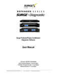
X1 External Power Supply
User Manual
Dear Client,
We are honored that you have chosen the CH X1 External Power Supply to take your existing CH Precision setup to the next level.
Our team made every effort to design and manufacture this top quality product and is proud to present it to you. We hope your
X1-powered system will bring you countless hours of emotion from your musical collection.
Before you start your musical journey, we kindly ask you to pay attention to the information contained within this manual. The X1,
as you will discover in the following pages, is a Swiss precision product designed for ultimate performance. However, in order to
reach sonic excellence, your unit needs to be setup and operated correctly and this what this manual is all about. If you have any
questions or require assistance, please don't hesitate to contact your authorized dealer.
We hope you will enjoy your CH Precision system for many years.
The Concert has just begun...
Cossy F.
Heeb T.
FCC-Notice
Note: This equipment has been tested and found to comply with the limits for a Class B digital device, pursuant to Part 15 of
the FCC Rules. These limits are designed to provide reasonable protection against harmful interference in a residential
installation. This equipment generates, uses and can radiate radio frequency energy and, if not installed and used in
accordance with the instructions, may cause harmful interference to radio communications. However there is no guarantee that
interference will not occur in a particular installation.
If this equipment does cause harmful interference to radio or television reception, which can be determined by turning the
equipment off and on, the user is encouraged to try to correct the interference by one or more of the following measures:
•
adjust or relocate the receiving antenna
•
increase the separation between the equipment and the receiver
•
connect the equipment into a mains outlet on a circuit different from that to which the receiver is connected
•
consult the dealer or an experienced radio/TV technician for help
Disposal – Environmental care
Directive 2002/96/EG of the European Parliament requires consumer electro-technical appliances to be
disposed separately and have to be indicated with the following symbol. Should you dispose this
component please do so in conformity with local and global legal and environmental regulations and
according to best practices. We strongly encourage you to recycle any batteries used with this component.
Table of contents
1 Technical Highlights.............................................................................................................................................................. 8
1.1 Electrical characteristics................................................................................................................................................ 9
1.1.1 Mains filtering.................................................................................................................................................... 9
1.1.2 Transformers...................................................................................................................................................... 9
1.1.3 Rectifying and filtering secondary windings.......................................................................................................... 9
1.1.4 Discrete regulation.............................................................................................................................................. 9
1.2 Mechanical construction............................................................................................................................................. 10
2 Before Use........................................................................................................................................................................ 11
2.1 Package content........................................................................................................................................................ 11
2.2 Safety notice............................................................................................................................................................. 11
2.3 User Manual............................................................................................................................................................. 12
2.4 Mains supply............................................................................................................................................................. 12
2.5 Transport and packaging............................................................................................................................................ 12
2.6 Cleaning................................................................................................................................................................... 13
2.7 Maintenance and service............................................................................................................................................ 13
3 Installation........................................................................................................................................................................ 14
3.1 Unpacking your unit.................................................................................................................................................. 14
3.1.1 Removing the transportation screw.................................................................................................................... 14
3.2 Positioning your unit................................................................................................................................................. 14
3.2.1 Unit position adjustment.................................................................................................................................... 14
3.2.2 Adjustment shaft covers.................................................................................................................................... 15
3.3 Connections............................................................................................................................................................... 16
3.3.1 CONTROL board................................................................................................................................................ 16
3.3.1.1 USB port.................................................................................................................................................. 17
3.3.1.2 Push-buttons............................................................................................................................................ 17
3.3.2 POWER SOURCE board...................................................................................................................................... 17
3.3.2.1 Power connector...................................................................................................................................... 17
3.3.3 Power cord receptacle and voltage selection....................................................................................................... 18
4 Operation.......................................................................................................................................................................... 19
4.1 Front panel............................................................................................................................................................... 19
4.2 Configuration............................................................................................................................................................ 20
5 Firmware update............................................................................................................................................................... 21
5.1 Introduction.............................................................................................................................................................. 21
5.2 Firmware Update procedure....................................................................................................................................... 21
5.2.1 Preparing the firmware image........................................................................................................................... 21
5.2.2 Updating the firmware...................................................................................................................................... 21
6 Troubleshooting................................................................................................................................................................. 23
7 Specifications..................................................................................................................................................................... 24
7.1 Specifications............................................................................................................................................................ 24
7.2 Dimensions............................................................................................................................................................... 25
7.3 Factory settings......................................................................................................................................................... 25
Rev 1.1
X1 User Manual
7
1
Technical Highlights
CH products are proudly designed and manufactured in Switzerland by CH Precision Sàrl. Our engineers have put all their knowhow and ingenuity to bring you the X1, a top performance, ultra low-noise, high current capable, DC-regulated external power
supply capable of powering up to two CH Precision units.
An X1 fitted with two regulation boards can be used to power two CH Precision devices simultaneously (such as a C1 controller, a
D1 disc transport or a L1 line preamplifier), with the advantage of dedicated transformers for analog and digital sections, and
cascaded voltage regulation. However, for ultimate performance, the X1 can be dedicated to power a single CH Precision unit.
X1 main components
(1)
(2)
(3)
(4)
(5)
(6)
(7)
(8)
(9)
8
Mains switch and power cord receptacle (on back panel)
Adjustment shafts and screws
High noise-rejection mains filter
Digital power supply transformer
Standby power transformer (ensures green mode Standby)
PMOLED display (on front panel)
Power supply output connectors (one or two per X1), must be connected to C1 and/or D1 and/or L1
USB A-type receptacle for firmware update
Power supply regulation boards (one or two per X1)
X1 User Manual
Rev 1.1
(10)
(11)
(12)
(13)
Motherboard
Filtering board
Rectifiers
Analog power supply transformer
1.1 Electrical characteristics
The X1 is a high grade linear power supply delivering the analog and digital DC power supplies required by a C1, D1 and a L1 on
high current capable M23 19-poles connector(s). Input AC voltage can be set to 100V, 115V or 230V AC to accommodate local
mains supply.
1.1.1 Mains filtering
The X1 transformer primary windings are individually filtered by massive RLC balanced networks. Both common mode and
differential harmonics and background noise get heavily attenuated. The critical analog power supplies are therefore isolated from
the noisy digital power supplies, leading to unprecedented micro-dynamics and signal-to-noise ratio.
1.1.2 Transformers
X1 houses no less than 3 magnetically shielded toroidal transformers, with static shields between primaries and secondaries:
•
An overspecified transformer is dedicated to analog power supplies, holding multiple sets of secondary windings (one of
them being exclusively used generate the purest Masterclock signal)
•
The second overspecified transformer is dedicated to digital power supplies, capable of delivering high current peaks
required by high performance DSPs and FPGAs, without radiating noise
•
A tiny transformer is used as standby transformer to ensure green standby mode, meeting the latest energy saving
regulations
All three transformers are mounted on a separate steel plate which is isolated from the main aluminium base plate through silent
blocks.
1.1.3 Rectifying and filtering secondary windings
A large array of low ESR capacitors follows fast switching rectifier bridges on all secondary windings. This creates a proper energy
reservoir responding extremely fast to high current demands, ensuring the transformers work under minimal stress condition,
leading to less radiated noise and excellent component preservation over time.
1.1.4 Discrete regulation
Discrete (power-transistor and op-amp based) ultra low noise regulators are used throughout the regulation stages of the X1 and
special care has been paid to the Masterclock power supply, which is completely decoupled from all other power supplies. This
ensures an ultra-low jitter clock source for the whole system.
Rev 1.1
X1 User Manual
9
When the X1 external power supply is connected to a CH Precision device, the latter's internal power supply is turned off (only the
standby transformer remains active, requiring its mains lead to remain plugged in). Turning the internal power supply off ensures
that no power supply induced noise or radiations are generated inside that unit, thus permitting optimal operating conditions for
the circuitry.
Moreover, all DC-regulated voltages delivered by the X1 get regulated once more inside the CH Precision unit it powers, leading to
vanishingly low noise floor.
1.2 Mechanical construction
The X1 external power supply is assembled from high-quality aluminium and steel elements with no visible screws on the front, top
and side panels. The front panel, base, side panels and top cover are machined from aluminium. The mains filtering section is
isolated from the rest of the machine in a dedicated compartment to avoid any contamination of unclean power distribution grid to
the secondary windings of the transformers by radiated noise. Pin assembly of all chassis elements provides smooth joints between
elements while screws every 6cm ensures protection against electromagnetic interferences. First class mechanical and chemical
surface treatments provide the luxury finish of the X1.
Four steel feet support the unit. Each feet ends with a elastomer ring to sit on delicate surfaces but is also equipped with a height
adjustable steel spike to fine tune unit positioning. Horizontal adjustment is done with the provided screwdriver through the four
adjustment shafts accessible from the top of the unit. In addition to providing convenient horizontal adjustment from the top of the
unit, the shafts also serve as vibration evacuation channels for any stacked unit. Special shaft covers are provided to interface with
the spikes of the stacked unit. Any vibration from the upper unit is transmitted by the shaft cover to the shaft and from the shaft to
the lower unit feet or spike, forming a privileged path for vibrations evacuation.
10
X1 User Manual
Rev 1.1
2
Before Use
Please read the following information carefully.
2.1 Package content
Make sure that the package content is complete. If not, please contact your authorized dealer. Your package should contain:
•
X1 external power supply unit
•
Power cord
•
One or two Power Link Cables (configuration-dependent)
•
Accessory box
•
User manual (this manual, located in the accessory box)
•
Adjustment screwdriver (located in the accessory box)
•
4x adjustment steel spikes (located in the accessory box)
•
4x adjustment shafts steel stacking covers (located in the accessory box)
•
4x adjustment shafts aluminum top covers (located in the accessory box)
Please store the packaging for future transportation. Check your X1 external power supply for apparent damages. In case of
damage, please contact your authorized dealer. If your X1 is still very cold following transport, please let it warm up to room
temperature before powering it up (in order to avoid condensation inside the unit).
2.2 Safety notice
Make sure to observe the following rules:
•
Install your X1 external power supply unit on a stable base
•
Do not install your X1 near water
•
Always handle with care. The X1 is quite heavy, so ask someone to help you handle it
•
Do not expose the unit to any kind of liquid
•
Do not install in direct sunlight or near any heat source such as radiators or other apparatus generating heat
Rev 1.1
X1 User Manual
11
•
Do not install in a confined space and allow sufficient airflow around the unit
•
Do not operate under high ambient temperature (>40°C) or with extremely high humidity such as in humid cellars
•
Only use options and accessories specified or recommended by the manufacturer
•
Only connect CH Precision compatible devices (such as C1, D1 or L1)
•
Do not open the unit nor try to service it. Do not install any option board yourself. Always refer to a qualified technician
for service, maintenance or hardware upgrades. Failure to do so will void the unit's warranty
2.3 User Manual
Please read this manual carefully before making connections or operating your X1 external power supply. Keep this manual at
hand for future reference. If after reading this manual you feel unsure of how to make connections or how to operate the unit,
please contact your local authorized dealer.
2.4 Mains supply
Make sure to use 3 terminals (phase, neutral and earth) power cords. Make sure that the mains voltage selection at the back of
the unit matches your local mains voltage.
Always disconnect your X1 external power supply from the AC wall socket in the following cases:
•
When making connections (it is also recommended to disconnect the rest of the system from AC wall power)
•
When cleaning the unit
•
During thunderstorms
•
When unused for a long period of time
Make sure your X1 external power supply is disconnected from other CH Precision devices when running a self-test.
2.5 Transport and packaging
The X1 external power supply must always be stored in its original packaging for transportation. Doing so will ensure optimal level
of protection to your unit. Therefore, keep the packaging in a dry and clean place for future use.
In addition, the transformer base plate must be secured for transportation (to avoid excessive constraints on the silent blocks
isolating the chassis from transformer vibrations). This is done by inserting 3 transportation screws at the bottom of the unit. Do
not forget to install these screws before transportation and remove them during installation of the unit at its new location.
12
X1 User Manual
Rev 1.1
Finally we recommend to remove the adjustment spikes and to put them into the accessory box for transportation. Indeed,
vibrations during transport may cause the adjustment spikes to move from their fully retracted position. There is a risk of
scratching the piece of furniture the unit is installed onto if the spikes are not fully retracted.
2.6 Cleaning
Use a soft, dry towel or cloth for cleaning. Never use any solvent or liquids as they may damage the surface or penetrate inside
the unit.
2.7 Maintenance and service
The X1 external power supply contains no user serviceable parts. Do not try to open, modify or repair your X1 yourself. This will
void any warranty. Your X1 must be checked by a qualified technician in any of the following cases:
•
The unit is not functioning properly
•
The mains cable or the power cord receptacle is damaged
•
The Power Link Cable or M23 19-poles connector is damaged
•
The unit has been dropped or presents external damage
•
The X1 has been exposed to liquids (such as rain) or unknown substances
Rev 1.1
X1 User Manual
13
3
Installation
3.1 Unpacking your unit
Unpack the X1 external power supply and store the packaging for future transportation. Be careful when lifting the X1 as the unit
is heavy (over 20kg). Get someone to help you if necessary. When unpacking and installing the X1, take care not to damage the
high quality surface treatments.
3.1.1 Removing the transportation screws
The transformer base plate must be secured during transportation to avoid damage to the isolating silent blocks. Three
transportation screws are located at the bottom of the unit. To remove the transportation screws, slightly tilt the unit on its side and
unscrew it. Do not tilt the unit on the front or back panels as this may damage the connectors.
Transportation screws locations
(1) Transportation screws. Must be mounted for transport and removed during installation
3.2 Positioning your unit
Position the X1 unit on a stable base. Allow airflow around the unit.
3.2.1 Unit position adjustment
The X1 external power supply is equipped with height adjustable feet. When delivered from factory, four adjustment spikes are
located in the accessory box. Insert them into each of the four adjustment shaft. Use the provided screwdriver to make the
required height adjustments.
When the spikes are fully retracted, the X1 sits on elastomer rings to protect the piece of furniture the unit sits on. Optional CH
support discs can be inserted underneath the unit to protect the piece of furniture from being scratched by the spikes.
14
X1 User Manual
Rev 1.1
Adjustment shafts, feet and spikes
(1)
(2)
(3)
(4)
Adjustment shafts. Insert spikes and use the provided screwdriver to adjust individual feet spikes
Feet
Adjustment spike heads (when inserted into adjustment shafts)
Adjustment spike
3.2.2 Adjustment shaft covers
Once the position of the unit is adjusted, place the appropriate shaft covers on the four adjustment shafts. There are two types of
shaft covers delivered with your X1 unit. One type of shaft cover (stacking cover, made of steel) is used when different CH units
are stacked. This type of cover includes a receptacle to receive the corresponding spike of the unit placed just above. By doing so,
mechanical vibrations are optimally transmitted to ground and minimized inside CH units. The second type of shaft cover (top
cover, made of aluminium) is used when units are not stacked or for the unit at the top of the stack. It covers the shaft and
provides a smooth finish to the top of the unit. Shaft covers are located in the accessories box delivered with your X1 unit.
Never stack any component other than CH components on your X1. Never use the aluminum shaft covers (top covers) when
another CH component is to be stacked on top of your X1.
Shaft covers (left: stacking cover, right: top cover)
Rev 1.1
X1 User Manual
15
3.3 Connections
This section provides information on how to connect your X1 external power supply to your system. As the X1 can be configured to
power one or two CH Precision devices, it can be fitted with a single or two POWER SOURCE boards (the picture below shows an X1
with two POWER SOURCE boards).
Rear panel connections
(1)
(2)
(3)
(4)
(5)
(6)
(7)
(8)
USB port for software upgrades.
Push-button for software upgrades and display configuration
Push-button for X1 self-test and front LED brightness
Power Link Cable connector to power a CH precision unit, such as C1, D1 or L1
Power Link Cable connector to power a CH precision unit, such as C1, D1 or L1 (optional)
Power on/off switch
Power cord receptacle
Mains fuse and voltage selection
3.3.1 CONTROL board
The CONTROL board is factory installed into the X1. It provides a USB port for software updates and two push-buttons for
configuration. The following drawing shows the layout of the back panel of the CONTROL board:
16
X1 User Manual
Rev 1.1
CONTROL board back panel layout
3.3.1.1 USB port
The USB port on the CONTROL board is dedicated to the firmware update of the X1 unit. Do not use it for any other purpose. For
more information on unit firmware update, please refer to chapter 5 of this manual.
3.3.1.2 Push-buttons
Two push-buttons allow access to four functions, depending when they are pushed. Detailed information on that topic is provided in
chapter 4 (Operation) of this manual.
3.3.2 POWER SOURCE board
As an X1 can be used to power one or two CH Precision units, it can be fitted with one or two Power source boards. Each board has
its own set of discrete regulators for analog and digital voltage rails. The following drawing shows the layout of the back panel of
the POWER SOURCE board:
POWER SOURCE board back panel layout
3.3.2.1 Power connector
The interface between an X1 and a CH Precision unit is handled by the Power Link Cable, plugged to the 19-poles connector at both
ends.
Rev 1.1
X1 User Manual
17
Make sure both X1 and X1-powered unit are turned off completely (Power on/off switch in the off position) before connecting the
two units together. Insert the Power Link Cable plugs and secure them by fully tightening their outer ring.
Then both units can then be switched on (Power on/off switch in the on position). They will remain in standby until the X1-powered
device is taken out of standby (by pushing its inner encoder, or from its remote control).
The X1's wake up and standby operations are automatically taken care of by signals exchanged between the units through the
Power Link Cable, so no user action is required on the X1 once its power switch is in the on position.
3.3.3 Power cord receptacle and voltage selection
Make sure that the voltage selection is set to the correct value with respect to the AC mains voltage in your location. Connect the
power cord to the power cord receptacle and plug the power plug to an AC wall socket only after all the other connections were
made.
18
X1 User Manual
Rev 1.1
4
Operation
The X1 external power supply is designed to seamlessly integrate in a CH Precision setup. Once properly connected and set up, it
requires no user intervention to operate.
4.1 Front panel
Front panel elements
(1) Standby LED
(2) Display area (PMOLED display)
Like in all CH Precision products, the standby LED of the X1 is dimmed when the unit is in standby mode, i.e. when no connected
CH Precision unit is being powered. The brightness of the LED when the X1 is on (i.e. powering a unit) is user-adjustable (from fully
off to fully in 10% steps). The PMOLED display reports failures if any. During self-test, it also reports status of all power supplies. It
can be customized to remain off, continuously show status or to momentarily report changes.
When an X1 powers a CH Precision device, the powered devices report it on their AMOLED display:
44.1 > 705.6 kHz
SACD 6ch
-18.5 dB
7 0 0:28:34
AES EBU 1
J AUDIO IN
<
J INTERNAL
<
(1)
(1)
C1 display when X1-powered
D1 display when X1-powered
(1) X1-powered icon
Rev 1.1
X1 User Manual
19
4.2 Configuration
The PMOLED display and the LED behavior of the X1 are customizable through the two push-buttons located on the control plate at
the back of the unit.
When the X1 is powering a device or is in standby mode, short pushes to the “Front LED Brightness” button will increase the “ON
mode” brightness of the X1's front LED by 10%. When the X1 is in standby mode, the LED is dimmed. But then it powers a unit,
one may prefer it to be completely off (as in other CH products), very bright (to have strong visual confirmation that it is active),
or anything in between.
When the X1 is powering a device or is in standby mode, short pushes to the “Display message ON/Short/OFF” button will toggle
the three display modes.
20
•
“ON” means the display will continuously display status of the X1
•
“Short” means the display will indicate changes (such as X1 starting to power a device) for a couple of seconds
•
“OFF” means the display will only be turned on if a failure occurs
X1 User Manual
Rev 1.1
5
Firmware update
5.1 Introduction
The X1's operation is managed by a microcontroller. This type of components run a firmware which can be updated when needed,
for instance to support additional features or to correct bugs. The following sections describe how to update the firmware of your
X1 unit.
5.2 Firmware Update procedure
5.2.1 Preparing the firmware image
Before doing the actual firmware update, it is necessary to prepare the firmware update image. Firmware update images are
available in the form of compressed .zip files from our website at www.ch-precision.com.
The following procedure shows how to prepare the firmware image:
1. Start by downloading the latest X1 firmware image from www.ch-precision.com
2. Prepare a blank, FAT32 formatted USB stick. Please note that some USB sticks are not properly detected by the USB
interface of the X1. CH Precision recommends the use of Sandisk USB flash drives.
3. Decompress the firmware image .zip file to the root of your USB stick
After doing so, your USB stick should contain the following file:
•
X1_xxx.mc1:
Firmware update file for X1 Micro-controller
where 'xxx' indicates the software version number.
5.2.2 Updating the firmware
Once the USB stick is ready with the appropriate file, you can proceed with the update of the X1 unit firmware. To do so, follow
these steps:
1. Turn off all CH Precision components connected to the X1.
2. Turn the X1 off by setting the Power on/off switch to off.
3. Disconnect any CH Precision unit from the X1.
4. Prepare and insert the USB key containing the appropriate firmware image for your unit (as detailed above).
Rev 1.1
X1 User Manual
21
5. Keep the Firmware update push-button (located next to the USB receptacle at the back of the unit) pushed while
powering-up the unit (by setting the Power on/off switch to on).
6. The unit will start up in firmware update mode and will update its internal firmware with the image present on the
USB stick. Do not interrupt or unplug the unit until the firmware update is finished. This typically takes about 5
seconds.
7. Once the firmware update is finished, the units goes into standby mode. You can then remove the USB stick.
8. To verify that the firmware update was successful, you can perform a self-test check. The current firmware in use will
be displayed, along with the internal state of power supplies.
9. Switch off the X1 unit (Power on/off switch to off) before plugging back CH Precision component(s) to be powered by
the X1 unit.
Note: The firmware update process can last several seconds, do NOT interrupt it!
If the firmware update procedure fails, try to download the latest software images from www.ch-precision.com , use another USB
stick, and rerun the firmware update procedure (don't forget to prepare the software update files and USB stick accordingly). If
failure persists, contact your authorized dealer.
22
X1 User Manual
Rev 1.1
6
Troubleshooting
Error
Action
No power (Front LED off)
Check the AC power cord
Check the power button at the back of the unit
Check the mains fuse on the AC power cord receptacle
Check the Power Link Cable
Disconnect matching CH Precision components (Power Link Cable) and turn X1 back on
X1 fails to power a component
Make sure Power Link Cable is properly connected and screwed all the way in at both ends
Disconnect matching CH Precision components (Power Link Cable) and run a self-test on X1
(report any displayed error to your CH Precision dealer)
Make sure X1-powered components are loaded with latest firmware (C1 firmware should be
V2.7 or newer, D1 firmware should be V3.1 or newer, L1 firmware should be V1.0 or newer)
Firmware update fails
Download the latest X1 firmware from www.ch-precision.com, prepare a software update
image on a FAT32 formatted USB stick and run the firmware update procedure again
USB flash drive for firmware
update is not detected by X1
Please try another brand of USB flash drive (e.g. Sandisk).
Troubleshooting
If the error cannot be corrected using the information from the above table, disconnect the unit from AC wall power and from the
rest of you system and contact your authorized dealer.
Rev 1.1
X1 User Manual
23
7
Specifications
7.1 Specifications
General
CH Precision compatible devices (so far)
C1 with firmware 2.7 or later
D1 with firmware 3.1 or later
L1 with firmware 1.0 or later
User control
Automatic on/standby functions remotely operated from connected C1
and/or D1 and/or L1
2 push-buttons at the rear of the unit for configuration
Display
256 x 64 pixels white PMOLED
Power supply
Selectable 100V, 115V or 230V AC, 47Hz to 63Hz
Power consumption (Standby mode)
< 1W
Power consumption (Normal operation)
40W/80W typical (1/2 devices powered), 400W max
Operating conditions
Temperature: +5C to +35C, humidity: 5% to 85% (no condensation)
Dimensions (L x D x H)
440mm x 440mm x 120mm (main body)
Weight
25kg
Software update
USB port for firmware update
Output voltages
Analog supplies
+/-19V DC
+/-8V DC
+11V DC
Digital supplies
+3.4V DC
+5.5V DC
+/-8V DC
+12V DC
Protections
Analog supplies
Over-voltage, under-voltage and over-current monitoring
Digital supplies
Over-voltage, under-voltage and over-current monitoring
Connections
Back panel
19-poles M23 connector compatible with C1, D1 & L1 external PSU
connector
Cable
2 meter cable with 19-poles M23 connectors (male & female)
Specifications
24
X1 User Manual
Rev 1.1
Design and Specifications are subject to change without notice
Weight and dimensions are approximate
Illustrations are informative only and may differ from actual production models
Casing design by Mana Ishoni
7.2 Dimensions
X1 External Power Supply dimensions
7.3 Factory settings
The following table lists the factory settings for your X1 External Power Supply unit:
SETTING
Value
LED BRIGHTNESS WHEN ON
80%
DISPLAY MESSAGE DURATION
Short
Factory settings
Rev 1.1
X1 User Manual
25
CH Precision Sàrl
ZI Le Trési 6D
CH-1028 Préverenges
SWITZERLAND
www.ch-precision.com
[email protected]
Made in Switzerland
26
X1 User Manual
Rev 1.1