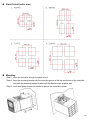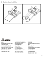
1
A Series Temperature Controller
Instruction Sheet
Thank you very much for purchasing DELTA A Series. Please read this instruction sheet to ensure correct
use before using your A series and please keep this instruction sheet handy for quick reference whenever
necessary.
Notice:
DANGER! Caution! Electric Shock!
1. Do not touch the AC terminals while the power is supplied to the controller in order
to avoid any electric shock.
2. Make sure the power is disconnected while checking the unit inside
WARNING!
This controller is an open-type temperature controller. Make sure to evaluate
any dangerous application in which a serious human injury or serious property
damage may occur.
1. Please use the specified solderless terminals (M3 screw, Max. width is 7.2mm or
less) and tighten them properly.
2. Do not allow the dust or metal fragments to fall inside the controller. These may
cause malfunction.
3. Never modify or disassemble the controller.
4. Do not wire to the No function terminals.
5. Make sure all wires are connected to the correct polarity of terminals.
6. Do not install and/or use the controller in places subject to:
• Dust or corrosive gases and liquid.
• High humidity.
• High radiation.
• Vibration and shock
• High voltage and high frequency
7. Must turn off the power when wiring and changing temperature sensor.
8. Be sure to use compensating wires that match the thermocouple types when
extending or connecting the thermocouple wires.
9. Please use wires with resistance when extending or connecting the wires of the
platinum resistance thermometer (RTD).
10. Please keep the wire route as short as possible when wiring platinum resistance
thermometer (RTD) to the controller and please route power wires as far away as
possible from load wires to avoid interferences and noise affection.
11. This controller is an open-type unit and it must be placed in an enclosure away
from high temperature, humidity, dripping water, corrosive materials, airborne
dust and electric shock or vibration.
12. This controller is an open-type unit and it must be placed in an enclosure away
from high temperature, humidity, dripping water, corrosive materials, airborne
dust and electric shock or vibration
1
13. Please make sure the power and signal instrument are all installed properly
before the power is supplied to the controller, otherwise these may cause serious
damage.
14. Please do not touch the terminals of the controller or repair the controller when
the power is supplied to the controller, otherwise these may cause electric shock.
15. Wait one minute after the power is disconnected for capacitors to discharge
and please do not touch any internal circuit within the waiting period.
16. Cleaning: Do not use acid and alkaline liquid. Please use soft, dry cloth to clean
the controller.
Names of Parts
• PV Display: to display the process value or parameter type.
• SV Display: to display set point, parameter operation read value,
manipulated variable or set value of the parameter.
• AT LED
: flashes when the Auto-tuning operation is ON.
• OUT LED : lights when the output is ON.
•
: Function key. Press this key to select the desired function
mode.
•
: Mode key. Press this key to set parameters within each
function mode.
: Temperature unit LEDs.
LED lights when this
parameter is configured for Celsius and
LED lights
when this parameter is configured for Fahrenheit.
•
,
• ALM1/ALM2 : Alarm output LED. The ALM1 and ALM2 LED lights
when Alarm 1/Alarm 2 output is ON.
•
: Up key. Press this key to increase values displayed on the
SV display. Holding down this key speeds up the
continuously increments.
•
: Down key. Press this key to decrease values displayed on
the SV display. Holding down this key speeds up the
continuously decrements.
Model Explanation
Series
DTA : Delta A Series Temperature Controller
Panel Size
4848 : W48 × H48mm
4896 : W48 × H96mm
7272 : W72 × H72mm
9696 : W96 × H96mm
Output Selection
R : Relay output
V : Voltage Pulse output
C : Current output (Control)
SPDT (4848 series is SPST), 250VAC, 5A
14V+10% ~ -20%(Max. 40mA)
4~20mA
Communication
Selection
0 : non-communication function
1 : with RS-485 function
(W × H)
2
Electric Specifications
Power Supply Voltage
100 to 240VAC
50/60Hz
Operation Voltage Range 85% to 110% of rated voltage
Power Consumption
5VA
Display Method
7-segment digit LED Display
Process value (PV): Red color, Set point (SV): Green color
Input Temperature Sensor
Control Method
Thermocouple: K, J, T, E, N, R, S, B
Platinum resistance thermometer (RTD): Pt100, JPt100
PID or ON/OFF control or manual tuning
Relay output: SPDT (4848 series is SPST), 250VAC, 5A
Control Output
Voltage Pulse output: DC 14V, Max. load current 40mA
Display Accuracy
Current output: 4 to 20mADC (Load resistance: Max. 600Ω)
0.1% of measuring range
Sampling Time
0.5 sec
Vibration Resistance
10 to 55Hz, 10m/s2 for 10min, each in X, Y and Z directions
Shock Resistance
Max. 300m/ s2, 3 times in each 3 axes, 6 directions
Operation Temperature
0
Storage Temperature
-20
Installation Site Altitude
10000ft.
Ambient Humidity
35% to 85% RH (non-condensing)
to 50
to +65
Parameters List
1. Operation function mode: Perform per the settings of related control parameters
LED Display
Explanation
RUN/STOP: Control setting begins. Run (
mode on the SV display.
Default
) or Stop (
)
RUN
ALARM1 HIGH: Upper-limit alarm 1
4.0
ALARM1 LOW: Lower-limit alarm 1
4.0
ALARM2 HIGH: Upper-limit alarm 2
4.0
ALARM2 LOW: Lower-limit alarm 2
4.0
Setting lock: Lock 1 (
), Lock 2 (
) or OFF (
)
on the SV display. Lock 1 mode can lock all settings and Lock 2 mode only
can lock others than SV value. When OFF mode is selected, the Lock
OFF
function will be OFF. If you press
and
key simultaneously, the
“Lock” status can be released and the controller will be back to the
previous display.
3
LED Display
Explanation
OUT: Output value display and output value adjustment in manual tuning
control (This function is not available in ON/OFF control or Auto-tuning
setting)
Default
0
2. Regulation function mode: Set the control parameters
LED Display Explanation
Default
), the execution
AT: Auto-tuning setting. When AT key is set to ON (
of the PID auto-tuning function is automatically started. (PID control)
OFF
P: Proportional Band (PID control)
2.1
I: Integral Time (PID control)
260
D: Derivative Time (PID control)
41
PdoF: Offset output when P or PD control function is ON.
(PID control and Ki=0)
0
ioF: Default value of integral volume when PID control function is ON and
integral time constant is not equal to 0(zero). AT can automatically set this
0
parameter. (PID control and Ki≠0)
HTS: Set Heating hysteresis when ON/OFF control function is ON.
0
CTS: Set Cooling hysteresis when ON/OFF control function is ON.
0
HTPD: PID heating control cycle setting (PID control)
Output Selection:
C, V : 4 sec
R
: 20 sec
CLPD: PID cooling control cycle setting (PID control)
TPOF: Regulate temperature deviation value
0
CRHI: Regulate 20mA output deviation value
0
CRLO: Regulate 4mA output deviation value
0
3. Initial setting function mode: Initial settings of the controller and communication parameters
LED Display Explanation
Default
INPUT: Select input temperature sensor type (Please refer to the contents
of the “Temperature Sensor Type and Temperature Range” for detail)
UNIT: Select temperature display unit,
(
) and
(
).
PT2
C
4
LED Display Explanation
Default
T-HIGH: Upper-limit of temperature range
500.0
T-LOW: Lower-limit of temperature range
-20.0
), ON/OFF control
CONTROL: Control method setting. PID (
(
), or manual tuning (
SWITCH: Select Heating (
PID
) on the SV display
) or Cooling (
) mode
HEAT
AL1 SET: Alarm 1 setting
0
AL2 SET: Alarm 2 setting
0
C WE: Communication write in function disable/enable
OFF
C NO: Communication address setting
1
BPS: Communication baud rate setting
9600
LENGTH: Communication data length setting
7
PARITY: Communication parity bit setting
E
STOP BIT: Communication stop bit setting
1
Note: Alarm settings should be set under initial setting function mode and then AL1H, AL1L,
AL2H and AL2L settings would be able to display in operation function mode.
Operation Explanation
There are three function modes of operation: operation, regulation and initial setting. When you turn the
power on, the operation function mode will be displayed. If
it will switch to the regulation function mode. If
switch to the initial setting function mode. If
key is pressed is pressed for one time,
key is pressed for more than 3 seconds, it will
key is pressed for one time while in the regulation
function mode or initial setting function mode, it will return to the operation function mode.
PV/SV: Set the temperature set point and display process temperature. Use
temperature set point.
to set the
5
Setting method: In operation function mode, regulation function mode and initial function setting mode,
press
key to select desired function and use
are completely changed, press
key to change settings. After the settings
key to save. Flow chart of settings and internal functions are
shown as below:
Press
Press
key less than 3 sec
key more than 3 sec
Operation
function mode
Regulation
function mode
Press
Initial setting
function mode
Press
key
Use
Auto-tuning is ON
to set
temperature of target
(In PID control or RUN mode)
Press
Press
Set PID Kp
(In PID control)
Press
Set PID Ki
(In PID control)
Press
Set temperature unit
Press
Set upper-limit of
temperature range
Upper-limit alarm 1
(This parameter is available only
when ALA1 function enables)
Press
Set PID Kd
(In PID control)
Press
Set lower-limit of
temperature range
Lower-limit alarm 1
(This parameter is available only
when ALA1 function enables)
Press
Set input type
Control setting
RUN or STOP
Press
Press
key
Press
Press
or
P/PD control Offset setting
(When PID control is ON and Ki=0,
set the value of PdoF; If Ki≠0, AT will
automatically set the value of ioF
Select control method
Upper-limit alarm 2
(This parameter is available only
when ALA2 function enables)
Press
Press
Press
or
Heating/Cooling hysteresis
(In ON/OFF control)
Select heating/cooling
fumctions
Lower-limit alarm 2
(This parameter is available only
when ALA2 function enables)
Press
Press
Press
Set Heating/Cooling
control cycle (In PID control)
Alarm 1 setting
Setting lock mode
or
Press
Press
Press
6
Output value display
and adjust
Regulate temperature
deviation value
Press
Press
Alarm 2 setting
Press
Return to temperature display
Regulate 20mA output
deviation value
(Display when current output)
Press
Regulate 4mA output
deviation value
(Display when current output)
Press
Return to auto-tuning setting
Communication write in
disable/enable
(only available when the controller
has RS-485 function)
Press
Communication
address setting
(only available when the controller
has RS-485 function)
Press
Communication baud
rate setting
(only available when the controller
has RS-485 function)
Press
Communication data
length setting
(only available when the controller
has RS-485 function)
Press
Communication parity
bit setting
(only available when the controller
has RS-485 function)
Press
Communication stop
bit setting
(only available when the controller
has RS-485 function)
Press
Return to input type setting
Heating and Cooling Functions
There are two functions to control temperature, heater and cooler. The heating function actuates when
the process temperature (PV) is getting down and the cooling function cools when the process
temperature is getting high. It is impossible to operate both functions simultaneously in this controller,
therefore only one function can be selected and it is either heating function or cooling function.
7
Temperature Sensor Type and Temperature Range
Input Temperature Sensor Type
Register
Value
Platinum resistance (Pt100) type3
15
0.0 to 100.0
Platinum resistance (Pt100) type2
14
-20.0 to 500.0
Platinum resistance (Pt100) type1
13
-200 to 600
Platinum resistance (JPt100) type2
12
0.0 to 100.0
Platinum resistance (JPt100) type1
11
-20.0 to 400.0
Thermocouple (TC) B type
10
100 to 1800
Thermocouple (TC) S type
9
0 to 1700
Thermocouple (TC) R type
8
0 to 1700
Thermocouple (TC) N type
7
-200 to 1300
Thermocouple (TC) E type
6
0 to 600
Thermocouple (TC) T type2
5
-20.0 to 400.0
Thermocouple (TC) T type1
4
-200 to 400
Thermocouple (TC) J type2
3
-20.0 to 400.0
Thermocouple (TC) J type1
2
-100 to 850
Thermocouple (TC) K type2
1
-20.0 to 500.0
Thermocouple (TC) K type1
0
-200 to 1300
LED Display
Temperature Range
Input Error Indication
Setting value
Temperature sensor is Measured temperature exceeds
not connected
temperature range
Unknown input
PV
8
Setting value
Temperature sensor is Measured temperature exceeds
not connected
temperature range
Unknown input
SV
Alarm Outputs
There are two groups of alarm outputs and each group can select ten alarm types in the initial setting
function mode. The alarm output is activated when the temperature of target (PV) is getting higher or
lower than set value (SV).
Set
Value
0
1
2
Alarm Type
Alarm Output Function
Output OFF
Alarm function disabled
ON
Deviation upper- and lower-limit:
This alarm output operates when PV value is higher OFF
than set value of SV+(AL-H) or lower than set value of
SV-(AL-L)
SV-(AL-L).
ON
Deviation upper-limit:
This alarm output operates when PV value is higher OFF
than set value of SV+(AL-H).
SV
SV+(AL-H)
SV
SV+(AL-H)
ON
3
4
5
6
7
8
9
Deviation lower-limit:
This alarm output operates when PV value is lower OFF
than set value of SV-(AL-L).
SV-(AL-L) SV
ON
Reverse deviation upper- and lower-limit:
This alarm output operates when PV value is in the OFF
range of set value of SV+(AL-H) and SV-(AL-L).
SV-(AL-L) SV
Absolute value upper- and lower-limit:
ON
This alarm output operates when PV value is higher
OFF
than set value of AL-H or lower than set value of AL-L.
AL-L 0
Absolute value upper-limit:
ON
This alarm output operates when PV value is higher
OFF
than set value of AL-H.
0
Absolute value lower-limit:
ON
This alarm output operates when PV value is lower
OFF
than set value of AL-L.
AL-L 0
Deviation upper- and lower-limit with standby
ON
sequence:
OFF
This alarm output operates when PV value reaches set
SV-(AL-L) SV
value (SV value) and the value is higher than set value
of SV+(AL-H) or lower than set value of SV-(AL-L).
ON
Deviation upper-limit with standby sequence:
This alarm output operates when PV value reaches set OFF
value (SV value) and the reached value is higher than
SV
set value of SV+(AL-H).
SV+(AL-H)
AL-H
AL-H
SV+(AL-H)
SV+(AL-H)
9
Set
Value
10
Alarm Type
Alarm Output Function
ON
Deviation lower-limit with standby sequence:
This alarm output operates when PV value reaches the OFF
set value (SV value) and the reached value is lower
SV-(AL-L)
than set value of SV-(AL-L).
SV
Note: AL-H and AL-L include AL1H, AL2H and AL1L, AL2L.
With standby sequence: It means that the alarm output would be temporarily disabled until when PV value
reaches the set value. Then, the alarm output will start to operate.
Communication Parameters List
Condition of use: Controller must support RS-485 communication function.
Supporting transmission speed: 2400, 4800, 9600, 19200, 38400bps
Not supporting for the communication format of 7, N, 1 or 8, O, 2 or 8, E, 2
Communication protocol: Modbus (ASCII)
Available communication address: 1 to 255, 0 is broadcast address
Function code: 03H is to read the contents of register (Max. 3 words). 06H is to write 1 (one)
word into register.
Addresses and contents of data register
Address
Content
Explanation
4700H
Process value (PV)
Measuring unit is 0.1, updated one time in 0.5
second
4701H
Set point (SV)
Unit is 0.1,
4702H
Upper-limit alarm 1
4703H
Lower-limit alarm 1
4704H
Upper-limit alarm 2
4705H
Lower-limit alarm 2
4706H
Upper-limit of temperature range
4707H
Lower-limit of temperature range
4708H
Kp Proportional band
The data content should not be higher than the
temperature range
The data content should not be lower than the
temperature range
1 to 9999, unit is 0.1
4709H
Ki Integral time
0 to 9999
470AH
Kd Differential time
0 to 9999
470BH
Heating/Cooling hysteresis
0 to 9999
470CH~ 470FH
4710H
Input temperature sensor type
4711H
Control method
4712H
Heating/Cooling control cycle
Proportional control offset error
value
4713H
or
Reserved
Please refer to the contents of the “Temperature
Sensor Type and Temperature Range” for detail
0: PID (default), 1: ON/OFF, 2: manual tuning
1 to 99 second
0% to 100%
10
Address
Content
Explanation
4714H
Temperature regulation error
value
-127 to +127
4715H
Alarm 1 type
Please refer to the contents of the “Alarm
Outputs” for detail
4716H
Alarm 2 type
Please refer to the contents of the “Alarm
Outputs” for detail
4717H
4718H
4719H
Temperature unit display selection
: 1 (default), : 0
Heating/Cooling control Selection Heating: 0 (default), Cooling: 1
Control Run/Stop setting
Run: 1 (default), Stop:0
Communication write in disabled: 0 (default)
Communication write in selection
Communication write in enabled: 1
Software version
V1.00 indicates 0×100
471AH
471BH
Communication Protocol
Command code: 03H, read N words. The maximum value of N is 3.
For example, reading continuous two words from starting data address 4700H of controller with
communication address 01H.
ASCII mode:
Command message:
STX
ADR 1
ADR 0
CMD 1
CMD 0
Starting data
address
Number of data
(count by word)
LRC CHK 1
LRC CHK 0
END 1
END 0
Response message:
‘:’
‘0’
‘1’
‘0’
‘3’
‘4’
‘7’
‘0’
‘0’
‘0’
‘0’
‘0’
‘2’
‘B’
‘3’
CR
LF
STX
ADR 1
ADR 0
CMD 1
CMD 0
Number of data
(count by byte)
Content of start
address 2102H
Content of start
address 2103H
LRC CHK 1
LRC CHK 0
END 1
END 0
‘:’
‘0’
‘1’
‘0’
‘3’
‘0’
‘4’
‘0’
‘1’
‘9’
‘0’
‘0’
‘0’
‘0’
‘0’
‘6’
‘7’
CR
LF
LRC check:
LRC check is the added sum from “Address” to “Data content”. For example, 01H + 03H + 47H + 00H +
00H + 02H = 4DH, then take the complementary of 2, B3H.
Command code: 06H, write 1 (one) word
For example, write 1000(03E8H) into the starting data address 4701H of controller with 01H.
11
ASCII mode:
Command message:
STX
ADR 1
ADR 0
CMD 1
CMD 0
Starting data
address
Data content
LRC CHK 1
LRC CHK 0
END 1
END 0
Response message:
‘:’
‘0’
‘1’
‘0’
‘6’
‘4’
‘7’
‘0’
‘1’
‘0’
‘3’
‘E’
‘8’
‘C’
‘6’
CR
LF
STX
ADR 1
ADR 0
CMD 1
CMD 0
Starting data
address
Data content
LRC CHK 1
LRC CHK 0
END 1
END 0
‘:’
‘0’
‘1’
‘0’
‘6’
‘4’
‘7’
‘0’
‘1’
‘0’
‘3’
‘E’
‘8’
‘C’
‘6’
CR
LF
External Dimensions (units: mm)
DTA4848
DTA4896
12
DTA7272
DTA9696
Terminals Connection
DTA4848
_
5A 250Vac
DC
4~20mA
14Vdc
+
RTD
+
Tc
1
6
11
2
7
12
3
8
13
4
9
DATA-
14
AC 100~240V
50~60Hz / 5VA
ALM2
ALM1
RS-485
-
or
5 10
DATA+
15
3A 250Vac
3A 250Vac
COM
13
DTA4896/DTA9696
DATA+
1 11
AC 100~240V
50~60Hz / 5VA
RS-485
2 12
DATA-
3 13
4 14
COM
3A 250Vac
5 15
ALM2
6 16 COM
7 17
Tc
RTD
ALM1
8 18 NC
+
9 19 NO
-
or
10 20 COM
3A 250Vac
5A 250Vac
-
DC
14Vdc
4~20mA
+
DTA7272
DATA+
1
9
AC 100~240V
50~60Hz / 5VA
RS-485
DATA-
2 10
3 11
4 12
5 13
Tc
COM
ALM2
ALM1
NC
RTD
6 14
+
7 15 NO
-
or
3A 250Vac
8 16 COM
5A 250Vac
DC
4~20mA
14Vdc
+
14
Panel Cutout (units: mm)
Mounting
Step-1. Insert the controller through the panel cutout.
Step-2. Insert the mounting bracket into the mounting groove at the top and bottom of the controller
and push the mounting bracket forward until the bracket stops at panel wall.
Step-3. Insert and tighten screws on bracket to secure the controller in place.
15
Mounting Bracket Installation
1.
2.
http://www.deltaww.com
ASIA
DELTA ELECTRONICS, INC.
TAOYUAN Plant/
31-1, SHIEN PAN ROAD,
KUEI SAN INDUSTRIAL ZONE
TAOYUAN 333, TAIWAN
TEL: 886-3-362-6301
FAX: 886-3-362-7267
NORTH/SOUTH AMERICA
DELTA PRODUCTS
CORPORATION
Sales Office/
P.O. BOX 12173
5101 DAVIS DRIVE
RTP, NC 27709 U. S. A.
TEL: 1-919-767-3813
FAX: 1-919-767-3969
EUROPE
DELTRONICS (Netherlands)
B.V.
Sales Office/
Industriegebied Venlo Nr. 9031
Columbusweg 20
NL-5928 LC Venlo
The Netherlands
TEL: 31-77-324-1930
FAX: 31-77-324-1931
16