1
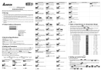
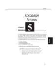
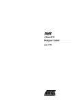
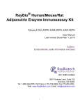
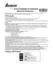
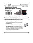
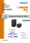
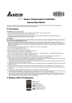
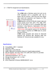
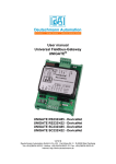
Series Temperature Controller Instruction Sheet Thank you very much for purchasing DELTA A Series. Please read this instruction sheet before using your A series to ensure proper operation and please keep this instruction sheet handy for quick reference. Precaution DANGER! Caution! Electric Shock! 1. 2. 3. Do not touch the AC terminals while the power is supplied to the controller to prevent an electric shock. Make sure power is disconnected while checking the unit inside. indicates that this Delta A Series Temperature Controller is protected throughout by DOUBLE INSULATION or The symbol REINFORCED INSULATION (equivalent to Class II of IEC 536). WARNING! This controller is an open-type temperature controller. Make sure to evaluate any dangerous application in which a serious human injury or serious property damage may occur. 1. Always use recommended solder-less terminals: Fork terminal with isolation (M3 screw, width is 7.0mm, hole diameter 3.2mm). Screw size: M3 x 6.5 (With 6.8 x 6.8 square washer). Recommended tightening torque: 0.4 N.m (4kgf.cm). 2 Applicable wire: Solid/twisted wire of 2 mm , 12AWG to 24AWG. Please be sure to tighten them properly. 2. Do not allow dust or foreign objects to fall inside the controller to prevent it from malfunctioning. 3. Never modify or disassemble the controller. 4. Do not connect anything to the “No used” terminals. 5. Make sure all wires are connected to the correct polarity of terminals. 6. Do not install and/or use the controller in places subject to: • Dust or corrosive gases and liquid. • High humidity. • High radiation. • Vibration and shock. • High voltage and high frequency 7. Must turn power off when wiring and changing a temperature sensor. 8. Be sure to use compensating wires that match the thermocouple types when extending or connecting the thermocouple wires. 9. Please use wires with resistance when extending or connecting a platinum resistance thermometer (RTD). 10. Please keep the wire as short as possible when wiring a platinum resistance thermometer (RTD) to the controller and please route power wires as far as possible from load wires to prevent interference and induced noise. 11. This controller is an open-type unit and must be placed in an enclosure away from high temperature, humidity, dripping water, corrosive materials, airborne dust and electric shock or vibration. 12. Please make sure power cables and signals from instruments are all installed properly before energizing the controller, otherwise serious damage may occur. 13. Please do not touch the terminals in the controller or try to repair the controller when power is applied to prevent an electric shock. 14. Wait at least one minute after power is disconnected to allow capacitors to discharge, and please do not touch any internal circuit within this period. 15. Do not use acid or alkaline liquids for cleaning. Please use a soft, dry cloth to clean the controller. 16. This instrument is not furnished with a power switch or fuse. Therefore, if a fuse or power supply switch is required, install the protection close to the instrument. Recommended fuse rating: Rated voltage 250 V, Rated current 1 A. Fuse type: Time-lag fuse Note: This controller does not provide overcurrent protection. Use of this product requires that suitable overcurrent protection device(s) must be added to ensure compliance with all relevant electrical standards and codes. (Rated 250 V, 15 Amps max). A suitable disconnecting device should be provided near the controller in the end-use installation. -1- Ordering Information c Series DTA: Delta A Series Temperature Controller d Panel Size (W × H) 4848: 1/16 DIN W48 × H48mm 4896: 1/8 DIN W48 × H96mm 7272: W72 × H72mm e Output Selection R: Relay output, SPDT (SPST: 1/16 DIN size), 250VAC, 5A V: Voltage Pulse output, 14V+10% ~ -20% (Max. 40mA) C: Current output, 4 ~ 20mA f Communication (Optional) 0: No interface 1: RS-485 g Current Transformer (CT) Function (Optional) None: No CT function (Current transformer is not provided) T: Current transformer is provided (only DTA7272 series support this function) 9648: 1/8 DIN W96 x H48 9696: 1/4 DIN W96 × H96mm Display, LED & Pushbuttons • PV Display: to display the process value or parameter type. • SV Display: to display set point, parameter operation read value, manipulated variable or set value of the parameter. • AT: flashes when the Auto-tuning operation is ON. • OUT: lights when the output is ON. : Function key. 1. Press this key to select the desired function mode. 2. Press this key to confirm a setting value. • : Mode key. Press this key to set parameters within each function mode. • o o o o C, F : Temperature unit LEDs. C LED lights when this parameter is configured for Celsius and F LED lights if configured for Fahrenheit. • ALM1 / ALM2 : Alarm output LED. The ALM1 / ALM2 LED lights when Alarm 1 or Alarm 2 output is ON. • • : Up key. Press this key to increase values displayed on the SV display. Hold down this key to speed up the incremental action. • : Down key. Press this key to decrease values displayed on the SV display. Hold down this key to speed up the decrements. Specifications Input voltage 100 ~ 240VAC Operation voltage range 85% to 110% of rated voltage Power consumption 5VA Display method 7-segment digit LED Display Process value (PV): Red color, Set point (SV): Green color Sensor type Control mode 50/60Hz max. Thermocouple: K, J, T, E, N, R, S, B, U, L, Txk 3-wire Platinum RTD: Pt100, JPt100 PID, ON/OFF control or Manual tuning Relay output:(resistive load): SPDT (SPST: 1/16 DIN size), 250VAC, 5A Control output Voltage Pulse output: DC 14V, Max. load current 40mA Display accuracy 0.1% of measuring range Current output: 4 to 20mADC (Load resistance: Max. 600Ω) Sampling rate 500 msec/per scan Vibration resistance 10 to 55Hz, 10m/s for 10min, each in X, Y and Z directions Shock resistance Max. 300m/ s , 3 times in each 3 axes, 6 directions Ambient temperature 2 2 o o 0 C ~ +50 C -2- o o Storage temperature -20 C ~ +65 C Relative humidity 35% ~ 80% (non-condensing) Altitude 2,000m or less Installation environment Installation Category 33, Pollution Degree 2. Conforming to EN61010-1 Panel protection level IP65 Parameters List 1. Operation Mode: Perform per the settings of related control parameters LED Display Explanation RUN/STOP: Control setting begins. Run ( ) or Stop ( Default ) mode on the SV display. RUN o ALARM1 HIGH: Upper-limit alarm 1 4.0 C ALARM1 LOW: Lower-limit alarm 1 4.0 C ALARM2 HIGH: Upper-limit alarm 2 4.0 C ALARM2 LOW: Lower-limit alarm 2 4.0 C o o o ), Lock 2 ( ) or OFF ( ) on the SV display. Lock 1 mode can lock all Setting lock: Lock 1 ( settings and Lock 2 mode only can lock others than SV value. When OFF mode is selected, the Lock function will be OFF. If you press and key simultaneously, the “Lock” status can be released and the controller will be back to the previous display. OUT: Output value display and output value adjustment in manual tuning control (This function is not available in ON/OFF control or Auto-tuning setting) CT: In case of using an external current transformer (CT), the controller displays the current value being measured by CT, if the control output is ON OFF 0 Read only 2. Regulation Mode: Set the control parameters LED Display Explanation AT: Auto-tuning setting. When AT key is set to ON ( automatically started. (PID control) ), the execution of the PID auto-tuning function is Default OFF P: Proportional Band (PID control) 47.6 I: Integral Time (PID control) 260 D: Derivative Time (PID control) 41 PdoF: Offset output when P or PD control function is ON. (PID control and Ki=0) 0 ioF: Default value of integral volume when PID control function is ON and integral time constant is not equal to 0(zero). AT can automatically set this parameter. (PID control and Ki≠0) 0 HTS: Set Heating hysteresis when ON/OFF control function is ON. 0 CTS: Set Cooling hysteresis when ON/OFF control function is ON. 0 HTPD: PID heating control cycle setting (PID control) CLPD: PID cooling control cycle setting (PID control) Output Selection: V: 4 sec. R: 20 sec. TPOF: Regulate temperature deviation value 0 CRHI: Regulate 20mA output deviation value (1unit = 0.1mA) 0 CRLO: Regulate 4mA output deviation value (1unit = 0.1mA) 0 3. Initial Setting Mode: Initial settings of the controller and communication parameters LED Display Explanation INPUT: Select input temperature sensor type (Please refer to the contents of the “Temperature Sensor Type and Temperature Range” for detail) o UNIT: Temperature display unit, C ( o ) and F ( Default PT2 o C ) T-HIGH: Upper limit for temperature range 500.0 -3- LED Display Explanation Default T-LOW: Lower limit for temperature range -20.0 CONTROL: Control method setting on the SV display: PID ( tuning ( ), ON/OFF control ( ), or manual PID ) ) or Cooling ( SWITCH: Select Heating ( HEAT ) action AL1 SET: Alarm 1 setting (See explanations in “Alarm Outputs” section.) 0 AL2 SET: Alarm 2 setting (See explanations in “Alarm Outputs” section.) 0 C SELECT : ASCII, RTU communication formats selection (Displayed when using serial communication) ASCII C WE: Write-in function disable/enable (Displayed when using serial communication) OFF C NO: Address setting (Displayed when using serial communication) 1 BPS: Baud rate setting (Displayed when using serial communication) 9,600 LENGTH: Data length setting (Displayed when using serial communication) 7 PARITY: Parity bit setting (Displayed when using serial communication) E STOP BIT: Stop bit setting (Displayed when using serial communication) 1 Note: Alarm values should be set in the initial setting mode so AL1H, AL1L, AL2H and AL2L would display in operation mode. Operation There are three modes of operation: operation, regulation and initial setting. When power is applied, controller gets into the operation mode. Press the key to switch to regulation mode. If the mode. Pressing the key is pressed for more than 3 seconds, controller will switch to the initial setting key while in the regulation mode or initial setting mode, forces the controller to return to the operation mode. PV/SV: Sets the temperature set point and displays the temperature process value. Use the point. and keys to set the temperature set key to select the desired function and use the Setting method: While in any function mode, press the settings. Press key to save the changes. The next flow chart shows how to switch for settings and internal functions: Regulation Mode Operation Mode Auto-tuning (In PID control and RUN mode) Use and keys to change Initial Setting Mode Set input type to set temperature of target Press V Press V Control setting RUN or STOP Set PID PB (In PID control) Press Press V Press Press V V V Lower-limit alarm 1 (The parameter is available only when ALA1 function enables) Set PID Td (In PID control) Press Press V -4- V Press V Set temperature unit Upper-limit alarm 1 (This parameter is available only when ALA1 function enables) Set PID Ti (In PID control) Press V Set upper-limit of temperature range Press V Set lower-limit of temperature range Press V Regulation Mode Operation Mode or P/PD control offset setting (When PID control is ON and Ki=0, set the value of Pdof; if Ki≠0, AT will automatically set the value of Iof) Press V or control cycle (In PID control) Press Press V Press V Press Press Press V V Press V Press V Press V Alarm 1 setting V Output value display and adjust Regulate temperature deviation value Press Select Heating/Cooling functions V Setting lock mode Set Heating/Cooling Select control mode V Lower-limit alarm 2 (This parameter is available only when ALA2 function enables) or Heating/Cooling hysteresis (In ON-OFF control) Press Initial Setting Mode Upper-limit alarm 2 (This parameter is available only when ALA2 function enables) Alarm 2 setting V CT function is selected ASCII, RTU communication formats Regulate 20mA output deviation value In case of using an external CT, the controller selection (Display when in current output) displays the current value being measured by CT, if the control output is ON. Press V Press return to temperature display V Write-in function disable/enable (Displayed when using serial communication) Regulate 4mA output deviation value (Displayed when in current output) Press Press return to auto-tuning setting Press V Address setting (Displayed when using serial communication) Press V Baud rate setting (Displayed when using serial communication) Press V Date length setting (Displayed when using serial communication) Press V Parity bit setting (Displayed when using serial communication) Press V Stop bit setting (Displayed when using serial communication) Press return to input type Heating and Cooling Control Temperature control is achieved either by heating or by cooling. The heating function starts when the process temperature (PV) is going down, and the cooling function when the temperature is getting high. It is impossible to operate both functions simultaneously in this controller. -5- Temperature Sensor Type & Temperature Range Input temperature sensor type Register value LED display Temperature range o Platinum resistance (Pt100) type 3 15 0.0 ~ 100.0 C Platinum resistance (Pt100) type 2 14 -20.0 ~ 500.0 C Platinum resistance (Pt100) type 1 13 -200 ~ 600 C Platinum resistance (JPt100) type 2 12 0.0 ~ 100.0 C Platinum resistance (JPt100) type 1 11 -20.0 ~ 400.0 C Thermocouple (TC) B type 10 100 ~ 1,800 C Thermocouple (TC) S type 9 0 ~ 1,700 C Thermocouple (TC) R type 8 0 ~ 1,700 C Thermocouple (TC) N type 7 -200 ~ 1,300 C Thermocouple (TC) E type 6 0 ~ 600 C Thermocouple (TC) T type 2 5 -20.0 ~ 400.0 C Thermocouple (TC) T type 1 4 -200 ~ 400 C Thermocouple (TC) J type 2 3 -20.0 ~ 400.0 C Thermocouple (TC) J type 1 2 -100 ~ 850 C Thermocouple (TC) K type 2 1 -20.0 ~ 500.0 C Thermocouple (TC) K type 1 0 -200 ~ 1300 C Thermocouple (TC) L type 16 -200 ~ 850 C Thermocouple (TC) U type 17 -200 ~ 500 C Thermocouple (TC) Txk type 18 -200 ~ 800 C o o o o o o o o o o o o o o o o o o Input Error Indication Set value Temperature sensor not connected Measured temperature value exceeds temperature range Unknown input PV SV Alarm Outputs There are up to two groups of alarm outputs and each group allows 13 alarm types in the initial setting mode. The alarm output is activated whenever the process temperature value (PV) is getting higher or lower than the set point of alarm limit. Set value Alarm type Alarm output operation Output OFF 0 Alarm function disabled 1 Deviation upper- and lower-limit: This alarm output operates when PV value is higher than the setting value SV + (AL-H) or lower than the setting value SV - (AL-L). 2 3 4 Deviation upper-limit: This alarm output operates when PV value is higher than the setting value SV + (AL-H). Deviation lower-limit: This alarm output operates when PV value is lower than the setting value SV- (AL-L). ON OFF SV-(AL-L) SV+(AL-H) OFF SV SV+(AL-H) ON OFF SV-(AL-L) ON Reverse deviation upper- and lower-limit: This alarm output operates when PV value is in the range of the setting value SV + (AL-H) and OFF SV-(AL-L) SV - (AL-L). -6- SV ON SV SV SV+(AL-H) Set value Alarm type 5 Absolute value upper- and lower-limit: This alarm output operates when PV value is higher than the setting value AL-H or lower than setting value AL-L. ON OFF 6 Absolute value upper-limit: This alarm output operates when PV value is higher than the setting value AL-H. ON OFF 7 Absolute value lower-limit: This alarm output operates when PV value is lower than the setting value AL-L. ON OFF 8 9 10 11 12 13 Alarm output operation Deviation upper- and lower-limit with standby sequence: This alarm output operates when PV value reaches set value (SV value) and the value is higher than the setting value SV + (AL-H) or lower than the setting value SV - (AL-L). Deviation upper-limit with standby sequence: This alarm output operates when PV value reaches set value (SV value) and the reached value is higher than the setting value SV + (AL-H). AL-H AL-L AL-H AL-L ON OFF SV-(AL-L) SV SV+(AL-H) SV SV+(AL-H) ON OFF Deviation lower-limit with standby sequence: This alarm output operates when PV value reaches the set value (SV value) and the reached value is lower than the setting value SV - (AL-L). ON OFF SV-(AL-L) Hysteresis upper limit alarm output: this alarm output operates if PV value is higher than the setting value SV + (AL-H). This alarm output is OFF when PV value is lower than the setting value SV + (AL-L). ON OFF Hysteresis lower limit alarm output: this alarm output operates if PV value is lower than the setting value SV - (AL-H). This alarm output is OFF when PV value is higher than the setting value SV - (AL-L). ON OFF CT alarm output: This alarm operates when the current measured by transformer (CT) is lower than AL-L or higher than AL-H (This alarm output is available only for the controller with current transformer). SV SV AL-L AL-H AL-H AL-L SV ON OFF AL-L SV AL-H Note: AL-H and AL-L include AL1H, AL2H and AL1L, AL2L. With standby sequence: Meaning that the alarm output would be temporarily disabled until the PV value reaches the set value. Then, the alarm output will operate. Current Transformer (CT) Function The Current Transformer (CT) function is used with the alarm output. When using a current transformer (CT) with the controller, change the corresponding alarm output mode to mode 13 (alarm output set value is 13), then turn to operation mode and set the current lower-limit and current upper-limit. You can set current alarm range between 0.5A ~ 30A, display resolution is 0.1A and measure accuracy is +/- 0.5A. Communication Parameters List Controller offers a RS-485 port for serial communication. • Supporting transmission speed: 2,400, 4,800, 9,600, 19,200, 38,400bps • Communication protocol: Modbus (ASCII) • Non-supported formats: 7, N, 1 or 8, O, 2 or 8, E, 2 • Available communication address: 1 to 255, 0 is broadcast address • Function code: 03H to read the contents of register (Max. 3 words); 06H to write 1 (one) word into register. Address 4700H (R) Content Explanation Process value (PV) Measuring unit is 0.1, updated one time in 0.5 second 4701H Set point (SV) Unit: 0.1 ( C or F) 4702H Upper-limit alarm 1 4703H Lower-limit alarm 1 4704H Upper-limit alarm 2 4705H Lower-limit alarm 2 4706H Upper-limit of temperature range o o The data content should not be higher than the temperature range 4707H Lower-limit of temperature range The data content should not be lower than the temperature range 4708H PB Proportional band 0.1 ~ 999.9, Unit: 0.1 4709H Ti Integral time 0 ~ 9,999 -7- Address 470AH Content Explanation Td Derivative time 0 ~ 9,999 470BH Heating/Cooling hysteresis 0 ~ 9,999 470CH Regulate 20mA current output deviation -100 ~ 54 470DH 470EH Regulate 4mA current output deviation Default value of integral volume -39 ~ 100 (1 unit = 0.1mA) 0 ~ 100% 4710H Input temperature sensor type Please refer to the contents of the “Temperature Sensor Type and Temperature Range” for detail 4711H Control method 0: PID (default), 1: ON/OFF, 2: manual tuning 4712H Heating/Cooling control cycle 1 ~ 99 second (1 unit = 0.1mA) 4713H Proportional control offset error value 0% ~100% 4714H Temperature regulation value -999 ~ 999, Unit: 0.1 4715H Alarm 1 type Please refer to the contents of the “Alarm Outputs” for detail 4716H Alarm 2 type Please refer to the contents of the “Alarm Outputs” for detail 4717H Temperature unit display selection o 4718H Heating/Cooling control Selection Heating: 0 (default), Cooling: 1 4719H Control Run/Stop setting Run: 1 (default), Stop: 0 471AH Communication write-in selection Communication write in disabled: 0 (default), Communication write in enabled: 1 471BH Software version 471CH Read LED status V1.00 indicates 0 x 100 b2: °F, b3: °C, b4: AL2, b5: AL1, b6: OUT, b7: AT 471DH Read KEY status b0: SET, b1: Select, b2: Up, b3: Down 471EH Read output amount Unit: % 4729H AT Setting OFF: 0 (default), ON:1 472AH Write output amount Code 0 Available on “manual control” only Normal operation (No error) Code 1 Initial process 472BH (R) o C : 1 (default), F : 0 Code 2 Initial status (Temperature is not stable) Code 3 Temperature sensor is not connected Code 4 Temperature sensor input error Code 5 Measured temperature value exceeds the temperature range Code 6 No Int. error Code 7 EEPROM Error 4731H Read / Write lock status 0: No Lock, 1: Lock1, 11: Lock2, 21: Lock3 4732H Event input switch 0: Event disable, 1: SV switch, 2: Run/Stop 4733H CT monitor value Unit is 0.1A Note: R refers to “read only” value Default Communication Response Setting Write hex value 1234 into register at 471BH and 1234 again into register at 4724H. Re-power DTA to complete the default setting. -8- Communication Protocol Command code to read N words: 03H. The maximum value of N is 3. For example, in order to read two words from controller 01 (address 01H) at starting data address 4700H, the command in ASCII mode is: ASCII mode: Command message: Response message: STX ‘:’ STX ‘:’ ADR1 ADR0 ‘0’ ‘1’ ADR1 ADR0 ‘0’ ‘1’ CMD1 CMD0 ‘0’ ‘3’ CMD1 CMD0 ‘0’ ‘4’ ‘7’ Number of data (count by byte) ‘0’ ‘4’ Starting data address Number of data (counted by word) ‘0’ ‘0’ Content of start address 4700H ‘0’ ‘0’ ‘0’ ‘2’ LRC CHK 1 LRC CHK 0 ‘B’ ‘3’ END 1 END 0 CR LF Content of start address 4701H ‘3’ ‘0’ ‘1’ ‘9’ ‘0’ ‘0’ ‘0’ ‘0’ ‘0’ LRC CHK 1 LRC CHK 0 ‘6’ ‘7’ END 1 END 0 CR LF LRC check: LRC check is the added sum from “Address” to “Data content”. For example, 01H + 03H + 47H + 00H + 00H + 02H = 4DH, then take the complementary of 2, B3H. Command code to write 1 word: 06H For example, in order to write 1000 (03E8H) in controller 01 (comm. address 01H) at the starting data address 4701H, the command in ASCII mode is: ASCII mode: Command message: STX ADR1 ADR0 CMD1 CMD0 Starting data address Data content LRC CHK 1 LRC CHK 0 END 1 END 0 Response message: STX ADR1 ADR0 CMD1 CMD0 ‘:’ ‘0’ ‘1’ ‘0’ ‘6’ ‘4’ ‘7’ ‘0’ ‘1’ ‘0’ ‘3’ ‘E’ ‘8’ ‘C’ ‘6’ CR LF Starting data address Data content LRC CHK 1 LRC CHK 0 END 1 END 0 -9- ‘:’ ‘0’ ‘1’ ‘0’ ‘6’ ‘4’ ‘7’ ‘0’ ‘1’ ‘0’ ‘3’ ‘E’ ‘8’ ‘C’ ‘6’ CR LF Terminal Identification DTA4848 5A 250Vac - 1 14Vdc DC 4~20mA 2 6 11 7 12 3 8 + RTD + Tc - or DTA7272 4 9 5 10 AC 100~240V 50~60Hz /5VA ALM2 13 DATARS-485 DATA+ 14 ALM1 15 COM DTA4896/DTA9648/DTA9696 DATA+ DATA+ RS-485 DATACT 1 9 RTD + - or RS-485 AC 100~240V 50~60Hz /5VA 2 10 DATA- 4 12 ALM2 6 14 NC 7 15 NO 8 16 3A 250Vac 5A 250Vac AC 100~240V 50~60Hz /5VA 2 12 4 14 COM 5 15 ALM2 6 16 COM ALM1 COM 1 11 3 13 3 11 COM 5 13 Tc 3A 250Vac 3A 250Vac 7 17 - RTD DC 4~20mA 14Vdc + + Tc - or 8 18 ALM1 NC NO 9 19 3A 250Vac 3A 250Vac 5A 250Vac - DC 4~20mA 14Vdc 10 20 COM + Mounting Step 1. Insert the controller through the panel cutout. Step 2. Insert the mounting bracket into the mounting groove at the top and bottom of the controller and push the mounting bracket forward until the bracket stops at panel wall. Step 3. Insert and tighten screws on bracket to secure the controller in place. (The screw torque should be 0.8kgf-cm to 1.5kgf-cm) 3 2 1 Mounting Bracket Installation 1. 2. - 10 - Panel Cutout & External Dimensions 1. Panel wall thickness should range from 1mm to 8mm 2. Provide at least 90 mm clearance around the controller for proper ventilation. (Dimensions are in millimeter and (inch)) DTA4848 45 0 60.0 min. +0.6 65.0 min. +0.6 45 0 DTA4896 DTA9648 DTA7272 - 11 - DTA9696 CT Wiring Method (if CT function is selected) - 12 -