1
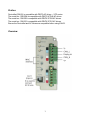
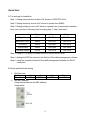
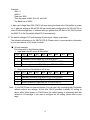
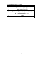
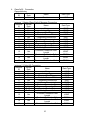
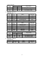
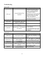
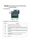
HTTP://www.deltaww.com/acdrives
DeviceNet(DN-02)
Instruction
ASIA
DELTA ELECTRONICS, INC.
TAOYUAN Plant/
31-1, SHIEN PAN ROAD,
KUEI SAN INDUSTRIAL ZONE
TAOYUAN 333, TAIWAN, R.O.C
TEL: 886-3-362-6301
FAX: 886-3-362-7267
NORTH/SOUTH AMERICA
DELTA PRODUCTS
CORPORATION
Sales Office/
P.O. BOX 12173, 5101 DAVIS
DRIVE, RTP, NC 27709, U. S. A.
TEL: 1-919-767-3813
FAX: 1-919-767-3969
EUROPE
DELTRONICS (Netherlands) B.V.
Sales Office/
Industriegebied Venlo Nr. 9031,
Columbusweg 20, NL-5928 LC
Venlo
The Netherlands
TEL: 31-77-342-1930
FAX: 31-77-342-1931
Table of Content
Preface ......................................................................................................................................................... 1
Overview...................................................................................................................................................... 1
Dimension ................................................................................................................................................... 2
Quick Start .................................................................................................................................................. 3
Configure the DN-02 According to Your Requirements ...................................................... 5
DeviceNet Objects .................................................................................................................................. 8
Troubleshooting ..................................................................................................................................... 13
Preface
DeviceNet (DN-02) is compatible with DELTA AC drives -- VFD series.
The model no.: DN-02M is compatible with DELTA VFD-M AC drives.
The model no.: DN-02B is compatible with DELTA VFD-B AC drives.
The model no.: DN-02S is compatible with DELTA VFD-S AC drives.
Ensure the DeviceNet and AC drives are compatible before using DN-02.
Overview
1
Dimension
DN-02
Network
Module
SP
ADD1
ADD2
Data Rate
2
Quick Start
A. The settings for Installation
Step 1. Setting communication format of AC drives to 19200 RTU 8,N,2.
Step 2. Setting frequency source of AC drives to operate from RS485.
Step 3. Setting run/stop source of AC drives to operate from communication interface.
Note: you can refer to following chart for setting step 1, step 2 and step 3.
M type
S type
B type
VFD_address
P88=1
P09-00=1
P09-00=1
Baud rate 19200
P89=2
P09-01=2
P09-01=2
RTU 8,n,2
P92=3
P09-04=3
P09-04=3
Freq. source
P00=3
P02-00=4
P02-00=4
Run/stop source
P01=4
P02-01=4
P02-01=4
Step 4. Using RJ11 (6 pins) to connect RS485 of DN-02 and AC drive.
Step 5. Adding the EDS files (saved in the disk) into DeviceNet management software.
Step 6. Using the operation method of DeviceNet management software for DN-02
connection.
B. Switch and Baud rate setting
1. Set Baud rate
Switch value
0
1
Baud Rate
125K
250K
2. Set MAC Address
Using decimal data set the MAC address,
Using switch
3
2
500K
Other
AUTO
Example:
Add1: 3
Add2: 6
Data rate: 250k
Then the value of MAC ID is 36, not 0x36;
The Baud rate is 250K;
If data rate is large than 500k, DN-02 will auto tuning the baud rate of DeviceNet at power
on. If address setting as 99 will RS 485 can setting data configuration 0x7100~0x710A or
class 95 data configuration. If address setting is greater than 63 and not 99, DN-02 will set
the MAC ID to the DeviceNet default ID 63 automatically.
C. The default settings of I/O poll message 4 bytes input 4 bytes output data
The following information is for DELTA VFD-M. Please refer to communication information
in your user manual of AC drives for detail.
■ I/O poll message
The information in the following tables
1. Input data from AC drives to DeviceNet
Byte
Bit7
Bit6
Bit5
Bit4
Bit3
Bit2
Bit1
0
LED Status ex: VFD-M is 2101H
1
Command Control status ex: VFD-M is 2101H
2
Frequency command (Low Byte) ex: VFD-M is 2102H
3
Frequency command (High Byte) ex: VFD-M is 2102H
2. Output data from DeviceNet to AC drives
Byte
Bit7
Bit6
Bit5
Bit4
Bit3
Bit2
Bit1
0
Operate Command (Low Byte) ex: VFD-M is 2000H
1
Operate Command (High Byte) ex: VFD-M is 2000H
2
Speed Reference (Low Byte) ex: VFD-M is 2001H
3
Bit0
Bit0
Speed Reference (High Byte) ex: VFD-M is 2001H
Note : If your DN-02 has not been set before, you can use it by connecting with DeviceNet
network without any settings. At this time, DN-02 provides a default I/O setting as
above table. When power on, DN-02 uses this default setting to exchange data with
network in I/O message. If you need to configure the I/O setting, please refer to next
page.
4
Configure the DN-02 According to Your Requirements
The following communication information is for DELTA VFD-M. Please refer to communication
information in your user manual of AC drive for detail.
■ Configure the DN-02 by DeviceNet
DN-02 supports a Object called DataConf (0X95), you can access this object by
DeviceNet configuration or management tools. The DataConf Object is defined as
follows:
Class 0x95 DataConfigure
Class Attributes
Attribute ID Access Rule
Name
Data Type
1
Get
Revision
UINT
Instance 1:
Attribute Access
Data Modbus
Name
Description
ID
Rule
Type Address
1
Get/Set
dlen_in
USINT 7100H Length of input data
2
Get/Set dlen_out USINT 7100L Length of output data
0: output address not continued
3
Get/Set out_state USINT
7101
1: output address continued
4
Get/Set data_in1
UINT
7102
1st word input data
5
Get/Set data_in2
UINT
7103
2nd word input data
6
Get/Set data_in3
UINT
7104
3rd word input data
7
Get/Set data_in4
UINT
7105
4th word input data
8
Get/Set data_out1
UINT
7106
1st word output data
9
Get/Set data_out2
UINT
7107
2nd word output data
10
Get/Set data_out3
UINT
7108
3rd word output data
11
Get/Set data_out4
UINT
7109
4th word output data
0: DN-02 will use this object for
I/O message
12
Get/Set config_flag USINT
710A
other: DN-02 use default
setting.
Common Services
Implemented for
Service Code
Service Name
Class
Instance
0X05
Yes
Yes
Reset
0x0E
Yes
Yes
Get_Attribute_Single
0x10
No
Yes
Set_Attribute_Single
Note: You can set this object for your application. When you finished this setting, you
must be set the instance 1 attribute 12 (config_flag) to 0. Otherwise, DN-02 will
still use default setting in I/O data exchange.
5
■ Configure the DN-02 by Delta Modbus
DN-02 still support Delta Modbus protocol. You may configure it by Delta Modbus
protocol. Modbus address assigned table is in above table. You may refer the AC
Driver manual for using Delta Modbus.
When you use Delta Modbus protocol to configure the DN-02, you must set the MAC
ID switch to 99 before power on to enter configure mode. If DN-02 enters configure
mode, all LED will be orange lamp and you can access address 0x7100-0x710A to
configure DataConf Object.
■ An Example for DataConf Object
If we had finished setting as follows:
Attribute
485
Value
Name
ID
address
(Hex)
1
7100H
dlen_in
6
2
7100L
dlen_out
8
3
7101
out_state
0
4
7102
data_in1
2000
5
7103
data_in2
2001
6
7104
data_in3
2002
7
7105
data_in4
0
8
7106
data_out1
2101H
9
10
11
12
7107
7108
7109
710A
data_out2
data_out3
data_out4
config_flag
2103H
2104H
010AH
0
Description
Set input data is 6 bytes
Set output data is 8 bytes
Output data address is not continued
Operate command
Speed reference
Bit 0: it means EF (external fault) on
when bit 0 is 1.
Bit 1: it means Reset when bit 1 is 1.
Not care
Get LED status and command control
status
Get Actual speed
Get output current
Get value of parameter 010A
Clear this value to use this setting
We have a data list according to above setting:
1. Input data from AC drives to DN-02
Byte
Bit7
Bit6
Bit5
Bit4
Bit3
Bit2
0
LED Status
1
Command Control status
2
Speed Actual(Low Byte)
3
Speed Actual(High Byte)
4
Output current (low byte)
5
Output current (high byte)
6
Value of parameter 010A (low byte)
7
Value of parameter 010A (high byte)
6
Bit1
Bit0
2. Output data from DN-02 to AC drives
Byte
Bit7
Bit6
Bit5
Bit4
Bit3
Bit2
0
Operate Command (Low Byte)
1
Operate Command (High Byte)
2
Speed Reference (Low Byte)
Bit1
3
Speed Reference (High Byte)
4
5
Bit 0: it means EF (external fault) on when bit 0 is 1.
Bit 1: it means Reset when bit 1 is 1.
Reserved
6
Not care
7
Not care
7
Bit0
DeviceNet Objects
■ Object Classes
Class
0x01
0x02
0x03
0x05
0x0f
0x95
Object
Identity
Message router
DeviceNet
Connection
Parameter
DataConf
1. Class 0x01 Identity
Class Attributes
Attribute
Access
ID
Rule
1
Get
2
Get
3
Get
6
Get
7
Get
Instance 1 :Drive Instance
Attribute
Access
ID
Rule
1
Get
2
Get
3
Get
4
Get
5
6
7
Get
Get
Get
Name
Data Type
Revision
MaxInstance
NumberofInstances
MaxIdClass
MaxIdInstance
UINT
UINT
UINT
UINT
UINT
Name
Data Type
VendorId
DeviceType
ProductCode
Revision
MajRev
MinRev
Status
Sn
ProdName
StrLen
ASCIIStr
UINT
UINT
UINT
Common Services
Implemented for
Service
Code
Class
Instance
0x05
No
Yes
0x0e
Yes
Yes
0x10
Yes
No
USINT
USINT
WORD
UDINT
USINT
STRING
Service Name
Reset
Get_Attribute_Single
Find_Next_Object_Instance
8
2. Class 0x02 Message router
Class attributes
Attribute
Access
Name
Data Type
ID
Rule
1
Get
Revision
UINT
6
Get
MaxIdClass
UINT
7
Get
MaxIdInstance
UINT
Instance 1 :
Attribute
Access
Name
Data Type
ID
Rule
2
Get
NumAvailable
UINT
3
Get
NumActive
UINT
Common Services
Service
Implemented for
Service Name
Code
Class
Instance
0x0e
Yes
Yes
Get_Attribute_Single
3. Class 0x03 DeviceNet
Class Attributes
Attribute
Access
ID
Rule
1
Get
Instance 1 :Drive Instance
Attribute
Access
ID
Rule
1
Get
2
Get
3
Get/Set
4
Get/Set
5
Get
Name
Data Type
Revision
UINT
Name
Data Type
MACID
BaudRate
BusofInterrupt
BusofCounter
AllocationInfo
AllocationChioce
MasterNodeAddress
MACIDSwitchChanged
BaudRateSwitchChanged
MACIDSwitchValue
BaudRateSwitchValue
USINT
USINT
BOOL
USINT
6
Get
7
Get
8
Get
9
Get
Common Services
Service
Implemented for
Code
Class
Instance
0x0E
Yes
Yes
0x10
No
Yes
0x4B
No
Yes
0x4C
No
Yes
BYTE
USINT
BOOL
BOOL
USINT
USINT
Service Name
Get_Attribute_Single
Set_Attribute_Single
Allocate_Master/Slave_Connection_Set
Release_Master/Slave_Connection_Set
9
4. Class 0x05 Connection
Class attributes
Attribute
Access
ID
Rule
1
Get
Name
Data Type
Revision
UINT
Instance 1 :Master/Slave Explicit Message Connection
Attribute
Access
Name
ID
Rule
1
Get
State
2
Get
InstanceType
3
Get
TransportClassTrigger
4
Get
ProducedConnectionId
5
Get
ConsumedConnectionId
6
Get
InitialCommCharacteristics
7
Get
ProducedConnectionSize
8
Get
ConsumedConnectionSize
9
Get/Set
ExpectedPackedRate
12
Get/Set
WatchdogTimeoutAction
Produced Connection Path
13
Get
Length
14
Get
Produced Connection Path
Consumed Connection Path
15
Get
Length
16
Get
Consumed Connection Path
Instance 2 :Polled I/O Connection
Attribute
Access
Name
ID
Rule
1
Get
State
2
Get
InstanceType
3
Get
TransportClassTrigger
4
Get
ProducedConnectionId
5
Get
ConsumedConnectionId
6
Get
InitialCommCharacteristics
7
Get
ProducedConnectionSize
8
Get
ConsumedConnectionSize
9
Get/Set
ExpectedPackedRate
12
Get/Set
WatchdogTimeoutAction
Produced Connection Path
13
Get
Length
14
Get
Produced Connection Path
Consumed Connection Path
15
Get
Length
16
Get
Consumed Connection Path
10
Data Type
USINT
USINT
USINT
UINT
UINT
BYTE
UINT
UINT
UINT
USINT
USINT
EPATH
USINT
EPATH
Data Type
USINT
USINT
USINT
UINT
UINT
BYTE
UINT
UINT
UINT
USINT
USINT
EPATH
USINT
EPATH
Common Services
Service
Implemented for
Code
Class
Instance
0x05
No
Yes
0x0E
Yes
Yes
0x10
No
Yes
Service Name
Reset
Get_Attribute_Single
Set_Attribute_Single
5. Class 0x0f Parameter
Class attributes
Attribute
Access
Name
Data Type
ID
Rule
1
Get
Revision
UINT
2
Get
MaxInstance
UINT
8
Get
ParaClassDescriptor
WORD
9
Get
ConfAssemblyInst
UINT
10
Get
NativeLanguage
USINT
Instance 1 :Paremeter Instance 1 through 114
Attribute
Access
Name
Data Type
ID
Rule
—
1
Get/Set
Parameter Value
2
Get
Link Path Size
USINT
—
3
Get
Link Path
4
Get
Descriptor
WORD
5
Get
Data Type
USINT
6
Get
Data Size
USINT
Common Services
Service
Implemented for
Service Name
Code
Class
Instance
0X05
Yes
No
Reset
0x0E
Yes
Yes
Get_Attribute_Single
0x10
No
Yes
Set_Attribute_Single
6. Class 0x95 DataConf
Class attributes
Attribute ID Access Rule
1
Get
Name
Revision
11
Data Type
UINT
Instance 1:
Attribute ID Access Rule
1
Get/Set
2
Get/Set
3
Get/Set
4
Get/Set
5
Get/Set
6
Get/Set
7
Get/Set
8
Get/Set
9
Get/Set
10
Get/Set
11
Get/Set
12
Get/Set
Common Services
Service
Implemented for
Code
Class
Instance
0X05
Yes
Yes
0x0E
Yes
Yes
0x10
No
Yes
Name
dlen_in
dlen_out
out_state
data_in1
data_in2
data_in3
data_in4
data_out1
data_out2
data_out3
data_out4
config_flag
Data Type
USINT
USINT
USINT
UINT
UINT
UINT
UINT
UINT
UINT
UINT
UINT
USINT
Service Name
Reset
Get_Attribute_Single
Set_Attribute_Single
12
Troubleshooting
Network LED:
State
LED is off
Flashing Green LED
Green LED
Flashing Red LED
Red LED
Module LED:
State
Indication
No power/duplicate ID not
completed.
Corrective Actions
1. Verify that the power supply of
DN-02 is connected and that
power is reaching the DN-02
through the connector.
2. Make sure one or more nodes are
communicating on the network.
3. Make sure at least one other
node on the network is
operational at the same time and
data rate as the DN-02.
Online/not connected.
Online/connected. One or more
connections established
Online/Time-out. I/O connection
timed out.
1. Ensure that all nodes have
unique address.
Network failure. Failed duplicate
2. If all node addresses are unique,
ID or Bus-off.
check network for correct media
installation.
Indication
Corrective Actions
Ensure that the connected AC drive
LED is off
No power/not online
is powered and connected to the
DN-02.
DN-02 has passed all operational
Waiting for I/O data. No I/O, or
Flashing Green LED
tests and is waiting to pass I/O data
PLC in program
between the DN-02 and AC drives.
Green LED
I/O operational
Configuration problem. Bad CRC Reset internal I/O data of DN-02.
Flashing Red LED
of DN-02 parameters or flash Please refer to Data Configuration
program.
address assign for detail.
Hardware Failure. Failed internal
Red LED
Return to the factory.
or external RAM test.
13
SP LED:
State
Indication
LED is off
No power
Flashing Green LED
Green LED
Flashing Red LED
Red LED
Corrective Actions
There is no power applied to the
device.
DN-02 is reading the default
settings of AC drives.
DN-02 and AC drives is
communicating normally.
To check if the setting of
communication format of AC drives
CRC check faulted.
is correct. Please refer to the
installation for detail.
1. To check if the connection
between AC drive and DN-02
RS485 is correct.
Connection failure/no connection
2. Re-wire the AC drive connection
and ensure that the wire
specification is correct.
14