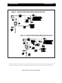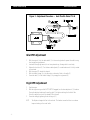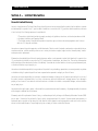
1
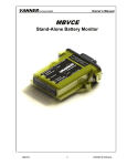
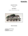
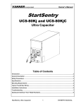
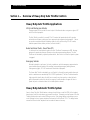
AutoThrottle Manual
Vanner Power Group
Section 1 — Overview of Heavy-Duty Auto Throttle Controls
Heavy Duty Auto Throttle Applications
Utility and Maintenance Vehicles
Increases engine RPM to provide full current output of the alternator when using various types of DC
and AC tools and equipment.
The Auto Throttle is excellent for use with DC to AC inverters that operate electric drills, grinders,
exhaust fans and blowers, plastic pipe fusion equipment and engineering test equipment. (Vanner
can provide a complete electrical distributing system for utility vehicles using DC to AC inverters,
alternator power boosters, battery isolators, and auto throttles.)
Bucket and Boom Trucks - Power Take-Offs
In vehicles with on-board hydraulic systems, the Auto Throttle will increase engine RPM, allowing
equipment to operate at maximum efficiency and provide proper operating pressures. The Auto
Throttle can be activated by a hydraulic pressure switch, which turns it on when the hydraulic system
is engaged.
Emergency Vehicles
Particularly desirable in police cars, fire trucks, ambulances, and other emergency equipment when
current exceeds alternator output at idle resulting from operating emergency rotating beacons,
flashing warning lights, DC to AC inverters and other electrical equipment.
The Vanner Auto Throttle is activated by an on/off switch (or through the master module disconnect
switch on ambulances as mandated by KKK-A-1822D specifications). The Auto Throttle releases the
high engine idle instantly when the shift lever is moved to any drive position or when the brake
pedal is depressed to prevent the vehicle from surging. It reactivates when the gear shift lever is
placed into park or neutral and when the foot brake pedal is released.
Heavy Duty Automatic Throttle System
Vanner’s Heavy Duty Auto Throttle features a strong solenoid that can control the RPM’s of the toughest
diesel engine, under the most extreme environmental conditions. The twenty pound pull power of the Auto
Throttle provides positive and constant RPM engine control. A key design feature incorporating a vernier
control allowing one-hand, precise adjustment has been built into the Model 73-46. This design feature
ensures that the most critical adjustment can be made with ease and accuracy.
-1-
AutoThrottle Manual
Vanner Power Group
Model—73-46
A Heavy Duty Automatic Throttle
System consisting of the solenoid/
cable assembly and the control
module assembly.
Model—73-48
The 73-48 Installation Kit consists
of an ON/OFF toggle switch,
02264* isolation diode, fuse, and
fuse holder.
Heavy Duty Auto Throttle System
Model 73-46
Replacement Parts
Part Number
Description
02264
73-44
02031
02045
05235
B00167
05006
25 amp bridge rectifier
73-46 solenoid and 46" cable assembly
Control module with harness
Solenoid without cable assembly
30 amp Relay (‘96 Chevy Diesel 6.5L)
46" Cable Assembly
Ring Terminal 1/4"
Conserve Fuel and Eliminate Over-Revving
With the Volt Guard Low Voltage Actuator
When your battery is fully
charged the Volt Guard allows
the engine to idle until the
voltage drops to 12.5 volts. It
then automatically activates the
Auto Throttle until the battery
has reached approximately 13.8
volts at which time the throttle is
released after approximately 90
seconds. The Volt Guard
automatically repeats this
process as often as necessary.
Volt Guard Low Voltage Actuator
Model 70-VG
The Volt Guard can be used with Vanner as well as many other makes of automatic throttle
controls provided they are electrically activated (see wiring chart on back).
-2-
AutoThrottle Manual
Vanner Power Group
Figure 1a - Automatic Throttle System Without Optional Volt Guard
Figure 1b - Automatic Throttle System With Optional Volt Guard
* Necessary for vehicles incorporating rear turn signal lamp with stoplight function. Not required if red/white stripe wire is connected to
the Center High Mount Stop Light (CHMSL) circuit. May substitute Radio Shack #276-1185 or Westinghouse #MB12A25V05.
Complete installation instructions on following pages.
-3-
AutoThrottle Manual
Vanner Power Group
Section 2 — Theory of Operation
The solenoid of the 73-46 is a continuous duty, 12-volt utilizing internal dual coils. The first, a pull-in
coil, is designed for 12-volt intermittent duty (increasing engine RPM to high idle); while the second; a
hold-in coil is designed for continuous duty (maintaining high idle engine RPM). The solenoid plunger is
activated by the pull-in coil and bottoms in the solenoid instantly, then is held in this position by the
hold-in coil. If the solenoid is operated continuously with the plunger in an unseated position (the pull-in
coil operating) the solenoid will burn out in 15 to 30 seconds.
The function of the control module is to sense the brake switch and neutral safety switch. When the foot
brake is not depressed or when the vehicle gear shift is in park or neutral, the control module activates the
solenoid, causing it to pull in, and the cable to activate the throttle linkage thus increasing the RPM of the
engine. Conversely, when wither the foot brake is applied or the vehicle is put into gear, the control
module responds and signals the solenoid to release instantly allowing the engine RPMs to reduce to a
slow idle.
The wring circuit functions as follows. The red wire is the power input for the system. It is desirable to keep
this wire as short as possible using at least a 12 gauge wire. The white wire carries the power from the
control module to the solenoid. The white/red wire carries the signal from the brake switch to the control
module. When the brake pedal is depressed, the module then deactivates the solenoid causing the engine
RPMs to drop to low idle. The white/black wire of the control module picks up a ground signal from the
neutral safety switch. When the neutral safety switch is in park or neutral, the control module sees ground,
and signals the solenoid to energize thus increasing the RPMs to a fast idle. The reverse happens when the
neutral safety switch senses the vehicle being placed in gear. The ground is not seen and the signal is sent
to the control module, which causes the solenoid to deactivate. Whenever the solenoid energizes, the
system will draw high amperage for a split second (the time it takes the solenoid plunger to bottom out)
then will reduce to a minimum draw for as long as the solenoid is activated. It is done this way to reduce
the power required for operation and to get the most strength out of a relatively small solenoid.
Section 3 — Troubleshooting
The first thing to check is the cable (Aut-09) going to the throttle linkage. If the cable housing was melted
by the exhaust manifold or otherwise damaged to a point where the stainless steal cable is jammed in the
housing, the cable won’t work and must be replaced.
The rest of the troubleshooting involves the electrical circuits. First test the solenoid. With the engine OFF,
disconnect the white wire where it is connected to the positive (+) terminal on the solenoid (Aut 0-11).
Using a fused 50-amp jumper, apply (+) 12 volts though a 50A ammeter to the positive (+) terminal
of the solenoid. Be certain that the negative terminal of the solenoid is securely grounded. The solenoid is
operating properly if the plunger pulls in, (audibly bottoms out) and the ammeter reading is between 0.5
and 1.0 amps. You should observe a momentary surge of up to 45 amps before the needle settles at the
-4-
Vanner Power Group
AutoThrottle Manual
0.5 to 1.0 amp reading. If the plunger does not pull in, and you see a 0.5 10 1.0 am reading, the
solenoid is not functioning correctly and must be replaced. If the plunger does pull in and bottoms out, but
your amp reading is outside the above ranges, the solenoid is not functioning properly and must be
replaced. This completes the electrical test of the solenoid.
Connect the 50A ammeter, positive to the end of the white wire form the control module and negative to
the positive (+) terminal of the solenoid. Activate the Auto Throttle system either by turning the ignition
switch “on” or through an auto throttle auxiliary on/off-switch if one has been installed. If the system is
functioning normally, the solenoid may bottom. You must continue testing to confirm if all components are
operating properly. Using a voltmeter (meter negative connected to the chassis) connect meter positive,
first to the red wire from the control module. You should measure 12 volts on the red wire. If the reading is
less than battery voltage, then check the red wire circuit for a blown fuse, defective on/off switch, etc. Next
connect the meter positive to the white/black wire from the control module. The voltmeter should read less
than 2 volts. If the reading is 2 to 8 volts, there is a conflicting electrical circuit in the vehicle system and
we recommend that a double pole, double throw relay be installed in the neutral safety switch circuit to
isolate the two conflicting systems. If the reading is above 8 volts, you should check for an open neutral
safety switch condition, a broken white/black wire, etc. For the final volt meter test, measure the voltage
on the white/red wire; you should read not more than 2 volts. A reading exceeding 2 volts indicates an
incorrect connection of the white/red wire at the brake switch. This connection should be made on the
brake light side of the brake switch.
To test the brake disable, apply the brake; the ammeter should drop to zero. Release the brake and the
ammeter will reflect a momentary surge of up to 45 amps then drop back to 0.5 to 1.0 amps. If this test
fails, the problem is in the control module (Asm-43). Replace the module.
As a final check of the neutral safety switch circuit, secure the vehicle by setting the parking brake and
blocking the wheels. Activate the 73-46 (solenoid will bottom) with the engine OFF. Drop the gearshift
lever into drive. The solenoid should release. If it does not release It may be due to (1) a non-functioning
control module, (2) a misaligned or shorted neutral safety switch, or (3) a partial grounding of the white/
black wire through the vehicle’s normal wiring system. First, disconnect the white/black wire at the neutral
safety switch. If the solenoid disengages, the control module is functioning normally. If the solenoid
remains in a seated position, replace the control module. To check for a misaligned or shorted neutral
safety switch, refer to the manufacturer’s test procedures. If (1) and (2) check properly, then correct (3) by
installing a double pole, double throw relay circuit to isolate the two conflicting systems.
-5-
AutoThrottle Manual
Vanner Power Group
Figure 2 - Adjustment Procedure — Auto Throttle Model 73-46
Idle RPM Adjustment
1. With the engine off, lock the cable endbell (1) to the mounting bracket to prevent the cable housing
from turning during adjustment.
2. Insert cable through ring terminal; do not crimp terminal eye, allowing cable to move freely.
3. Release the hex locknut (2). Turn the brass cable adjuster (3) counterclockwise until it is fully inserted
in the actuator.
4. With the engine OFF, actuate the solenoid.
5. With the throttle linkage (6) in the idle position, eliminate all slack in the cable (5).
6. Secure the cable (5) to the throttle linkage (6) by crimping the ring terminal (4).
High RPM Adjustment
1. Start the engine.
2. With the engine running and the AUTO THROTTLE engaged, turn the brass adjuster nut (3) clockwise.
Turning the adjuster clockwise will cause the cable (5) to tighten and bring the throttle off idle.
Continue to adjust the nut until the desired RPM is achieved.
3. Secure the setting by tightening the hex locking nut (2).
NOTE:
-6-
The Adjuster is designed to float in the solenoid. This freedom insures that there is no adverse
torque or twisting on the control cable.
Vanner Power Group
AutoThrottle Manual
Figure 3- Electrical Installation — Auto Throttle Model 73-46
NOTE 1: On vehicles where turn signal and hazard warning lights are incorporated with the red stop light
filaments, cut the wire as shown and install a BLOCKING DIODE.
A bridge rectifier (Radio Shack #276-1185 or Westinghouse MB12A25V05) can be used in
place of the blocking diode.
NOTE 2: The Vanner Model 73-46 Auto Throttle incorporates a dual coil solenoid. The first is a low
current holding coil that will keep the solenoid actuated once set. The second is a high current
pull-in coil. An internal switch disconnects the second coil when the solenoid plunger completes
its stroke. If the plunger is not allowed to bottom out or complete its stroke, the internal switch
will not disconnect the high current coil and the solenoid will burn out in about 30 seconds.
Therefore, the Auto throttle installation must include fuse protection A SLOW-BLO 3AG 8 Amp
fuse is recommended.
-7-
Vanner Power Group
AutoThrottle Manual
Section 4 — Limited Warranties
Domestic Limited Warranty
Vanner Inc. doing business as The Vanner Power Group, referred to herein as Vanner, warrants that this product is free from defects in materials
and workmanship for a period of one (1) year from date of installation or one and one half (1½) years from date of manufacture, whichever
is less if and only if the following requirement is complied with:
1. The product is installed and checked out properly according to all guidelines, instructions, and checkout procedures set forth
in the product Installation and Operating Manual.
2. The installer records all checkout data required and completes, signs, and returns the warranty registration card to Vanner
within ten (10) days after installation.
Vanner does not warrant its products against any and all defects when; Defect is a result of material or workmanship not provided by Vanner;
normal wear and tear, or defects caused by misuse or use in contrary to instructions supplied, neglect, accident, reversed polarity, unauthorized repairs and/or replacements.
All warranties of merchantability and fitness for a particular purpose: written or oral, expressed or implied, shall extend only for a period of one
(1) year from date of installation or one and one half (1½) years from date of manufacture, whichever is first. There are no other warranties
which extend beyond those described on the face of this warranty. Some states do not allow limitation on how long an implied warranty lasts,
so the above limitations may not apply to you.
Vanner does not undertake responsibility to any purchaser of its product for any undertaking, representation, or warranty made by any dealers
or distributors selling it’s products beyond those herein expressed unless expressed in writing by an officer of Vanner.
Vanner does not assume responsibility for incidental or consequential damages, including, but not limited to responsibility for loss of use of
this product, removal or replacement labor, loss of time, inconvenience, expense for telephone calls, shipping expense, loss or damage to
property, or loss of revenue. Some states do not allow the exclusion or limitation of incidental or consequential damages, so these limitations
may not apply to you.
Vanner reserves the right to repair, replace, or allow credit for any material returned under this warranty. Any damage caused by the customer
will be charged or deducted from the allowance.
All warranty work will be performed at Vanner’s factory, or authorized repair facility utilizing a valid Warranty Authorization Number (WAN)
prior to repair. Products shall be delivered to Vanner’s facility, freight prepaid and fully insured. Products repaired under warranty, or
replacement parts or products will be returned to North American location prepaid via same transportation means and level of service as
received, unless directed otherwise. Prepaid freight policy does not apply to locations outside North America.
-8-
Vanner Power Group
AutoThrottle Manual
International Limited Warranty
Vanner Inc. doing business as The Vanner Power Group, referred to herein as Vanner, warrants that this product is free from defects in materials
and workmanship for a period of one (1) year from date of installation or one and one half (1½) years from date of manufacture, whichever
is less if and only if the following requirement is complied with:
1. The product is installed and checked out properly according to all guidelines, instructions, and checkout procedures set forth
in the product Installation and Operating Manual.
2. The installer records all checkout data required and completes, signs, and returns the warranty registration card to Vanner
within ten (10) days after installation.
Vanner does not warrant its products against any and all defects when; Defect is a result of material or workmanship not provided by Vanner;
normal wear and tear, or defects caused by misuse or use in contrary to instructions supplied, neglect, accident, reversed polarity, unauthorized repairs and/or replacements.
All warranties of merchantability and fitness for a particular purpose: written or oral, expressed or implied, shall extend only for a period of one
(1) year from date of installation or one and one half (1½) years from date of manufacture, whichever is first. There are no other warranties
which extend beyond those described on the face of this warranty.
Vanner does not undertake responsibility to any purchaser of its product for any undertaking, representation, or warranty made by any dealers
or distributors selling it’s products beyond those herein expressed unless expressed in writing by an officer of Vanner.
Vanner does not assume responsibility for incidental or consequential damages, including, but not limited to responsibility for loss of use of
this product, removal or replacement labor, loss of time, inconvenience, expense for telephone calls, shipping expense, loss or damage to
property, or loss of revenue.
Vanner reserves the right to repair, replace, or allow credit for any material returned under this warranty. Any damage caused by the customer
will be charged or deducted from the allowance.
All warranty work will be performed at Vanner’s factory, or authorized repair facility utilizing a valid Warranty Authorization Number (WAN)
prior to repair. Products shall be delivered to Vanner’s facility, freight prepaid and fully insured. Transportation charges, fees, duties and
export documentation are the responsibility of the product’s owner.
-9-
List of Figures & Tables
Section 1
Overview of Heavy-Duty Auto Throttle Controls ............................................................. 1
Figure 1a — Automatic Throttle System Without Optional Volt Guard .................... 3
Figure 1b — Automatic Throttle System With Optional Volt Guard ........................ 3
Section 2
Theory of Operation ...................................................................................................4
Section 3
Troubleshooting ........................................................................................................ 4
Idle RPM Adjustment ......................................................................................... 6
Figure 2 — Adjustment Procedure - Auto Throttle Model 73-46 ............................ 6
High RPM Adjustment ........................................................................................ 6
Figure 3 — Electrical Installation - Auto Throttle Model 73-46 ............................. 7
Section 4
Limited Warranties ....................................................................................................8
VANNER POWER GROUP
Corporate Office:
4282 Reynolds Drive • Hilliard, Ohio 43026
Tel (614) 771-2718 • Fax (614) 771-4904
800-AC POWER
AUTO THROTTLE CONTROLS OWNER'S MANUAL
©
Copyright 1998, Vanner, Inc.
OM/A93900/06-9
AUTO THROTTLE CONTROLS
Owner's Manual OM/A93900/06-98
Volt Guard Actuator
Model 70-VG
Heavy Duty Auto Throttle System
Model 73-46
Vanner Power Group
4282 Reynolds Drive
Hilliard, Ohio 43026
www.vanner.com
800-AC POWER
Tel (614) 771-2718
Fax (614) 771-4904
Specifications Subject to Change
© Copyright 1998, Vanner Inc.
Printed in the U.S.A.
OM/A93900/0-98